Embed Size (px)
Citation preview

Modular Grease Trap (MGT), Modular
Grease Trap “S” Series (MGTS)
W.A. AGENTS: Civil & General Distributors
27 Oxleigh Drive MalagaPostal: PO Box 2706 Malaga WA 6944
Phone: 9249 4733 Fax: 9209 1220Email: [email protected]
October 2016
Modular Grease Trap (MGT, MGTS
and MGTA)
Installation Requirements
Water Corporation
22 Ethel Ave Brookvale NSW 2100 Postal: PO Box 255 Collaroy NSW 2097
Freecall 1800 626 753 Phone: 02 9939 8030 Fax: 02 9939 8027
Email: [email protected].
W.A. AGENTS: Civil & General Distributors
27 Oxleigh Drive MalagaPostal: PO Box 2706 Malaga WA 6944
Phone: 9249 4733 Fax: 9209 1220Email: [email protected]
Modular Grease Trap (MGT, MGTS
and MGTA)
Installation Requirements
Water Corporation
22 Ethel Ave Brookvale NSW 2100 Postal: PO Box 255 Collaroy NSW 2097
Freecall 1800 626 753 Phone: 02 9939 8030 Fax: 02 9939 8027
Email: [email protected].
Modular Grease Trap (MGT, MGTS
and MGTA)
Installation Requirements
Water Corporation
22 Ethel Ave Brookvale NSW 2100 Postal: PO Box 255 Collaroy NSW 2097
Freecall 1800 626 753 Phone: 02 9939 8030 Fax: 02 9939 8027
Email: [email protected].
W.A. AGENTS: Civil & General Distributors
27 Oxleigh Drive MalagaPostal: PO Box 2706 Malaga WA 6944
Phone: 9249 4733 Fax: 9209 1220Email: [email protected]
Modular Grease Trap (MGT, MGTS
and MGTA)
Installation Requirements
Water Corporation
22 Ethel Ave Brookvale NSW 2100 Postal: PO Box 255 Collaroy NSW 2097
Freecall 1800 626 753 Phone: 02 9939 8030 Fax: 02 9939 8027
Email: [email protected].
Halgan Installation Requirements
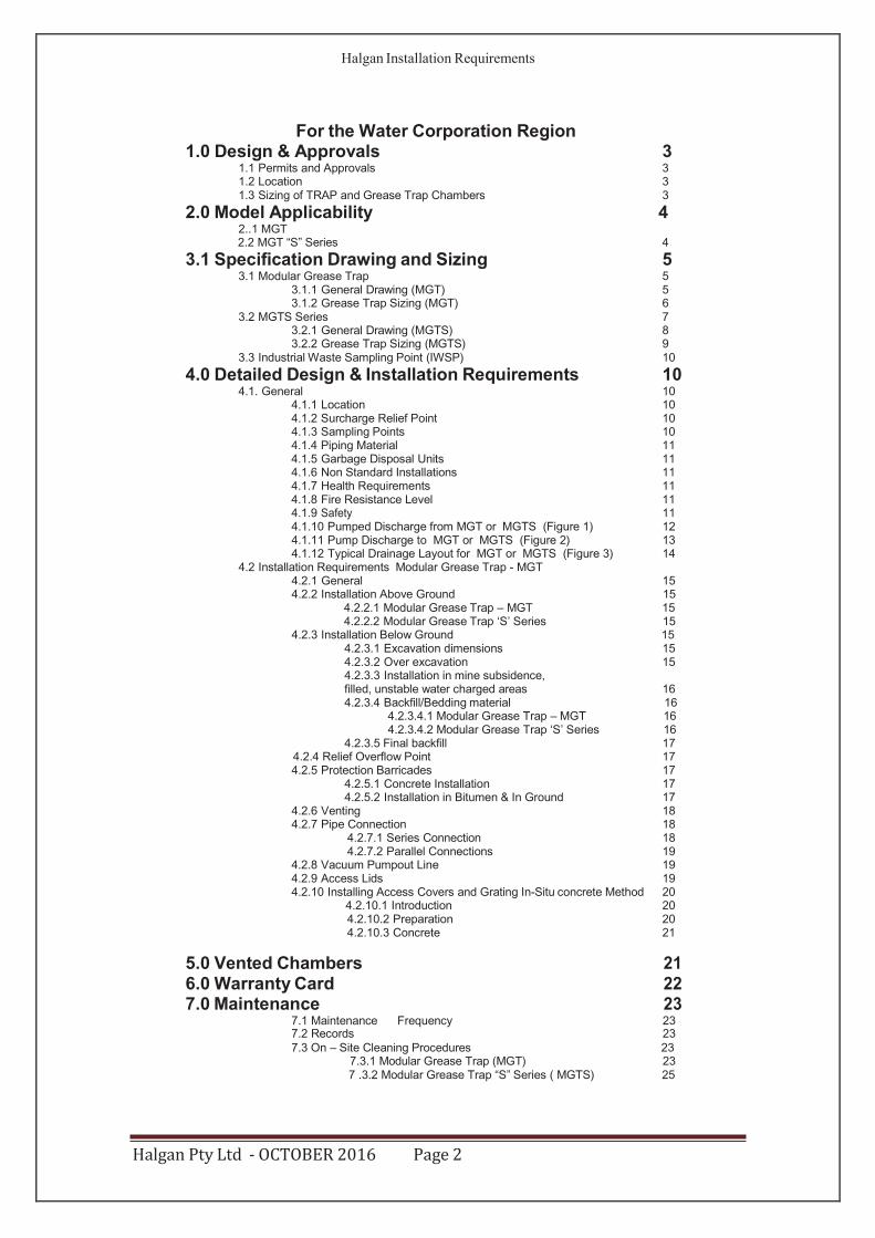
For the Water Corporation Region 1.0 Design & Approvals 3
1.1 Permits and Approvals 3 1.2 Location 3 1.3 Sizing of TRAP and Grease Trap Chambers 3
2.0 Model Applicability 4 2..1 MGT 2.2 MGT “S” Series 4
3.1 Specification Drawing and Sizing 5 3.1 Modular Grease Trap 5
3.1.1 General Drawing (MGT) 5 3.1.2 Grease Trap Sizing (MGT) 6
3.2 MGTS Series 7 3.2.1 General Drawing (MGTS) 8 3.2.2 Grease Trap Sizing (MGTS) 9
3.3 Industrial Waste Sampling Point (IWSP) 10
4.0 Detailed Design & Installation Requirements 10 4.1. General 10
4.1.1 Location 10 4.1.2 Surcharge Relief Point 10 4.1.3 Sampling Points 10 4.1.4 Piping Material 11 4.1.5 Garbage Disposal Units 11 4.1.6 Non Standard Installations 11 4.1.7 Health Requirements 11 4.1.8 Fire Resistance Level 11 4.1.9 Safety 11 4.1.10 Pumped Discharge from MGT or MGTS (Figure 1) 12 4.1.11 Pump Discharge to MGT or MGTS (Figure 2) 13 4.1.12 Typical Drainage Layout for MGT or MGTS (Figure 3) 14
4.2 Installation Requirements Modular Grease Trap - MGT 4.2.1 General 15 4.2.2 Installation Above Ground 15
4.2.2.1 Modular Grease Trap – MGT 15 4.2.2.2 Modular Grease Trap ‘S’ Series 15
4.2.3 Installation Below Ground 15 4.2.3.1 Excavation dimensions 15 4.2.3.2 Over excavation 15 4.2.3.3 Installation in mine subsidence, filled, unstable water charged areas 16 4.2.3.4 Backfill/Bedding material 16
4.2.3.4.1 Modular Grease Trap – MGT 16 4.2.3.4.2 Modular Grease Trap ‘S’ Series 16
4.2.3.5 Final backfill 17 4.2.4 Relief Overflow Point 17 4.2.5 Protection Barricades 17
4.2.5.1 Concrete Installation 17 4.2.5.2 Installation in Bitumen & In Ground 17
4.2.6 Venting 18 4.2.7 Pipe Connection 18
4.2.7.1 Series Connection 18 4.2.7.2 Parallel Connections 19
4.2.8 Vacuum Pumpout Line 19 4.2.9 Access Lids 19 4.2.10 Installing Access Covers and Grating In-Situ concrete Method 20
4.2.10.1 Introduction 20 4.2.10.2 Preparation 20 4.2.10.3 Concrete 21
5.0 Vented Chambers 21 6.0 Warranty Card 22 7.0 Maintenance 23
7.1 Maintenance Frequency 23 7.2 Records 23 7.3 On – Site Cleaning Procedures 23
7.3.1 Modular Grease Trap (MGT) 23 7 .3.2 Modular Grease Trap “S” Series ( MGTS) 25
Halgan Pty Ltd - OCTOBER 2016 Page 2
Halgan Installation Requirements
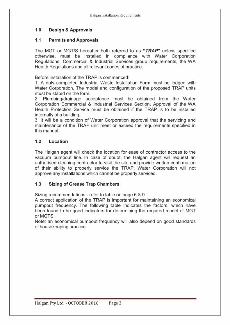
1.0 Design & Approvals
1.1 Permits and Approvals
The MGT or MGT/S hereafter both referred to as “TRAP” unless specified otherwise, must be installed in compliance with Water Corporation Regulations, Commercial & Industrial Services group requirements, the WA Health Regulations and all relevant codes of practice.
Before installation of the TRAP is commenced: 1. A duly completed Industrial Waste Installation Form must be lodged with Water Corporation. The model and configuration of the proposed TRAP units must be stated on the form. 2. Plumbing/drainage acceptance must be obtained from the Water Corporation Commercial & Industrial Services Section. Approval of the WA Health Protection Service must be obtained if the TRAP is to be installed internally of a building. 3. It will be a condition of Water Corporation approval that the servicing and maintenance of the TRAP unit meet or exceed the requirements specified in this manual.
1.2 Location
The Halgan agent will check the location for ease of contractor access to the vacuum pumpout line. In case of doubt, the Halgan agent will request an authorised cleaning contractor to visit the site and provide written confirmation of their ability to properly service the TRAP. Water Corporation will not approve any installations which cannot be properly serviced.
1.3 Sizing of Grease Trap Chambers
Sizing recommendations - refer to table on page 6 & 9. A correct application of the TRAP is important for maintaining an economical pumpout frequency. The following table indicates the factors, which have been found to be good indicators for determining the required model of MGT or MGTS. Note: an economical pumpout frequency will also depend on good standards of housekeeping practice.
Halgan Pty Ltd - OCTOBER 2016 Page 3
Halgan Installation Requirements
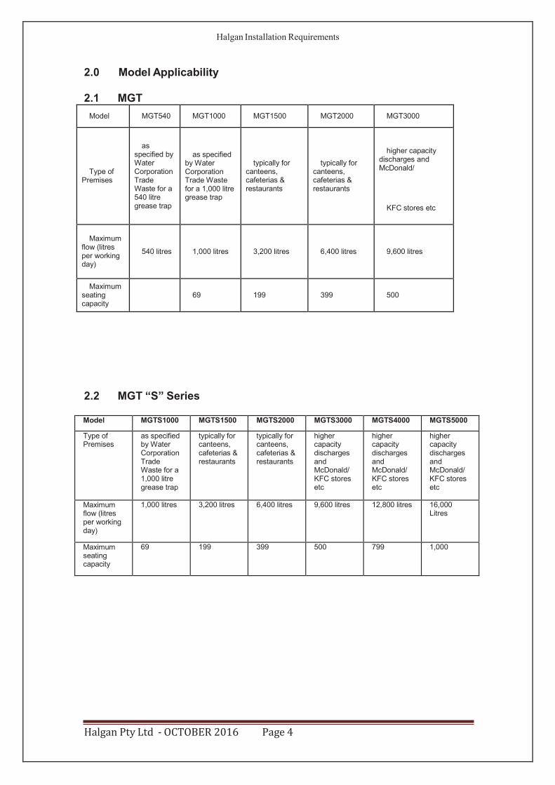
2.0 Model Applicability
2.1 MGT
Model MGT540 MGT1000 MGT1500 MGT2000 MGT3000
Type of Premises
as specified by Water Corporation Trade Waste for a 540 litre grease trap
as specified by Water Corporation Trade Waste for a 1,000 litre grease trap
typically for canteens, cafeterias & restaurants
typically for canteens, cafeterias & restaurants
higher capacity discharges and McDonald/
KFC stores etc
Maximum
flow (litres per working day)
540 litres
1,000 litres
3,200 litres
6,400 litres
9,600 litres
Maximum seating capacity
69
199
399
500
2.2 MGT “S” Series
Model MGTS1000 MGTS1500 MGTS2000 MGTS3000 MGTS4000 MGTS5000
Type of Premises
as specified by Water Corporation Trade Waste for a 1,000 litre grease trap
typically for canteens, cafeterias & restaurants
typically for canteens, cafeterias & restaurants
higher capacity discharges and McDonald/ KFC stores etc
higher capacity discharges and McDonald/ KFC stores etc
higher capacity discharges and McDonald/ KFC stores etc
Maximum flow (litres per working day)
1,000 litres 3,200 litres 6,400 litres 9,600 litres 12,800 litres 16,000 Litres
Maximum seating capacity
69 199 399 500 799 1,000
Halgan Pty Ltd - OCTOBER 2016 Page 4
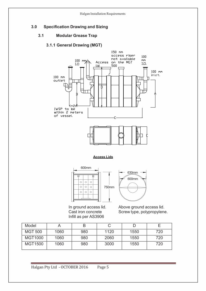
630mm
600mm
Halgan Installation Requirements
3.0 Specification Drawing and Sizing
3.1 Modular Grease Trap
3.1.1 General Drawing (MGT)
Access Lids
750mm
In ground access lid. Above ground access lid. Cast iron concrete Screw type, polypropylene. Infill as per AS3906
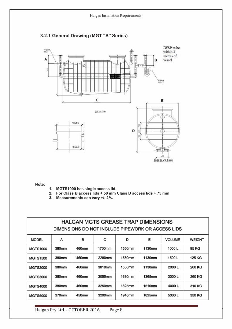
Model A B C D E
MGT 500 1060 980 1120 1550 720
MGT1000 1060 980 2060 1550 720
MGT1500 1060 980 3000 1550 720
Halgan Pty Ltd - OCTOBER 2016 Page 5
600mm
Halgan Installation Requirements
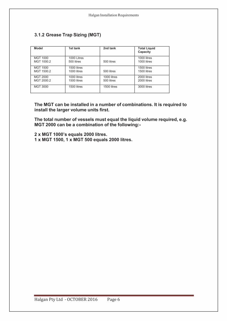
3.1.2 Grease Trap Sizing (MGT)
Model 1st tank 2nd tank Total Liquid Capacity
MGT 1000 MGT 1000.2
1000 Litres 500 litres
500 litres
1000 litres 1000 litres
MGT 1500 MGT 1500.2
1500 litres 1000 litres
500 litres
1500 litres 1500 litres
MGT 2000 MGT 2000.2
1000 litres 1500 litres
1000 litres 500 litres
2000 litres 2000 litres
MGT 3000 1500 litres 1500 litres 3000 litres
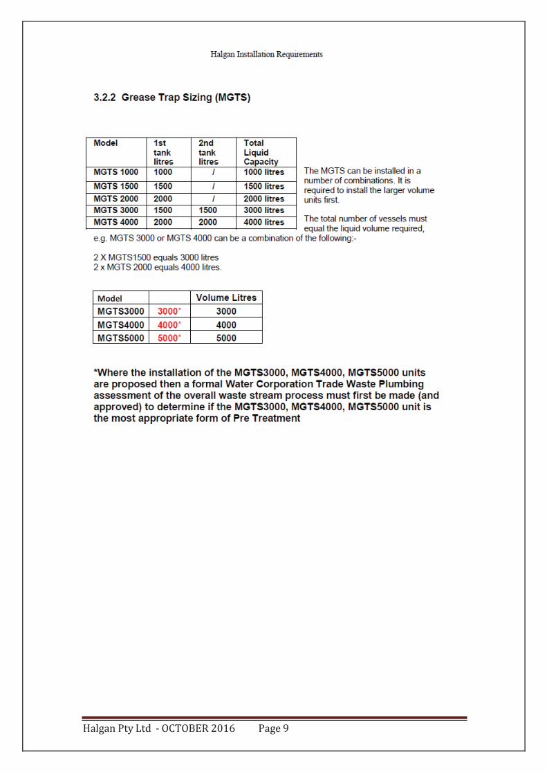
The MGT can be installed in a number of combinations. It is required to install the larger volume units first.
The total number of vessels must equal the liquid volume required, e.g. MGT 2000 can be a combination of the following:-
2 x MGT 1000’s equals 2000 litres. 1 x MGT 1500, 1 x MGT 500 equals 2000 litres.
Halgan Pty Ltd - OCTOBER 2016 Page 6
Halgan Installation Requirements
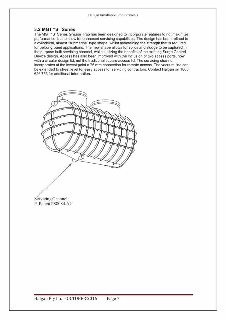
3.2 MGT “S” Series The MGT “S” Series Grease Trap has been designed to incorporate features to not maximize performance, but to allow for enhanced servicing capabilities. The design has been refined to a cylindrical, almost “submarine” type shape, whilst maintaining the strength that is required for below ground applications. The new shape allows for solids and sludge to be captured in the purpose built servicing channel, whilst utilizing the benefits of the existing Surge Control Device design. Access has also been improved with the inclusion of two access ports, now with a circular design lid, not the traditional square access lid. The servicing channel incorporates at the lowest point a 76 mm connection for remote access. The vacuum line can be extended to street level for easy access for servicing contractors. Contact Halgan on 1800 626 753 for additional information.
Servicing Channel P. Patent P88084.AU
Halgan Pty Ltd - OCTOBER 2016 Page 7
Halgan Installation Requirements
3.2.1 General Drawing (MGT “S” Series)
Note:1. MGTS1000 has single access lid.2. For Class B access lids + 50 mm Class D access lids + 75 mm3. Measurements can vary +/- 2%.
Halgan Pty Ltd - OCTOBER 2016 Page 8
Halgan Installation Requirements
3.2.1 General Drawing (MGT “S” Series)
Note:1. MGTS1000 has single access lid.2. For Class B access lids + 50 mm Class D access lids + 75 mm3. Measurements can vary +/- 2%.
Halgan Pty Ltd - OCTOBER 2016 Page 8
Halgan Pty Ltd - OCTOBER 2016 Page 9
Halgan Installation Requirements
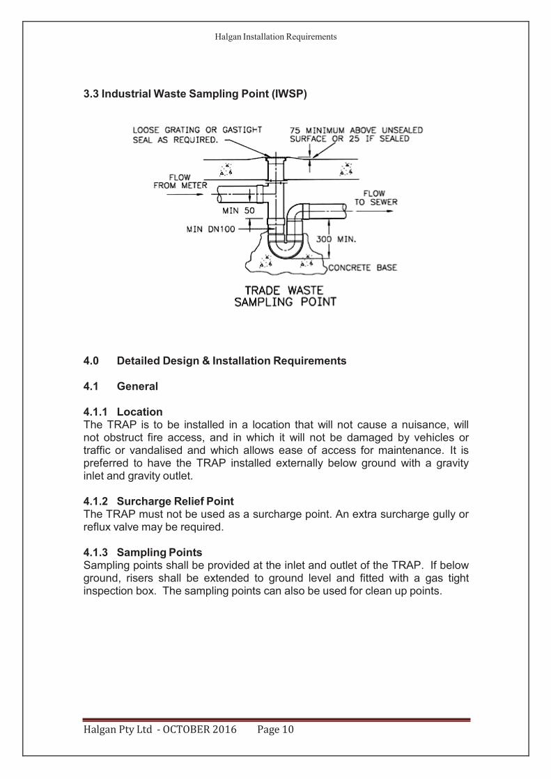
3.3 Industrial Waste Sampling Point (IWSP)
4.0 Detailed Design & Installation Requirements 4.1 General
4.1.1 Location The TRAP is to be installed in a location that will not cause a nuisance, will not obstruct fire access, and in which it will not be damaged by vehicles or traffic or vandalised and which allows ease of access for maintenance. It is preferred to have the TRAP installed externally below ground with a gravity inlet and gravity outlet.
4.1.2 Surcharge Relief Point The TRAP must not be used as a surcharge point. An extra surcharge gully or reflux valve may be required.
4.1.3 Sampling Points Sampling points shall be provided at the inlet and outlet of the TRAP. If below ground, risers shall be extended to ground level and fitted with a gas tight inspection box. The sampling points can also be used for clean up points.
Halgan Pty Ltd - OCTOBER 2016 Page 10
Halgan Installation Requirements
4.1.4 Piping Material Copper pipe and fittings shall not be used in trade waste installation as per AS/NZS 3500.
4.1.5 Garbage Disposal Units Garbage disposal units cannot discharge to the TRAP.
4.1.6 Non Standard Installations Certain installations or position of installations that are unusual due to particular circumstances or matters not covered by this specification or local codes may be submitted to Halgan for consideration. Water Corporation trade waste approval for these situations will be considered on an individual basis.
4.1.7 Health Requirements The TRAP shall be designed and installed in such a way as not to cause a danger to health arising from leakage, blockage or surcharging.
4.1.8 Fire Resistance Level The TRAP is to be installed to maintain the Fire Resistance Level (F.R.L.) as specified in the Building Code of Australia.
4.1.9 Safety The carrying out of work covered in this Technical Manual shall comply with the safety requirements of the relevant Authorities.
Halgan Pty Ltd - OCTOBER 2016 Page 11
MGT.
Halgan Installation Requirements
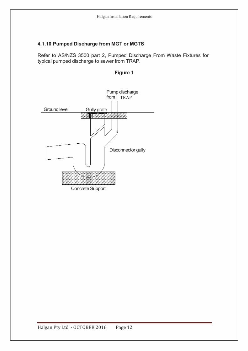
4.1.10 Pumped Discharge from MGT or MGTS
Refer to AS/NZS 3500 part 2, Pumped Discharge From Waste Fixtures for typical pumped discharge to sewer from TRAP.
Figure 1
Concrete Support
Halgan Pty Ltd - OCTOBER 2016 Page 12
Pump discharge from TRAP
Ground level Gully grate
Disconnector gully
Modular Grease Trap
Halgan Installation Requirements
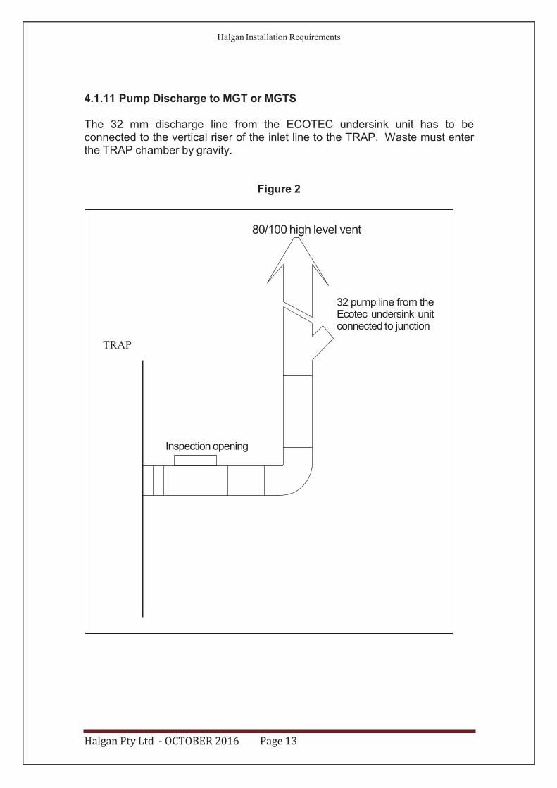
4.1.11 Pump Discharge to MGT or MGTS
The 32 mm discharge line from the ECOTEC undersink unit has to be connected to the vertical riser of the inlet line to the TRAP. Waste must enter the TRAP chamber by gravity.
Figure 2
Halgan Pty Ltd - OCTOBER 2016 Page 13
80/100 high level vent
32 pump line from the Ecotec undersink unit connected to junction
TRAP
Inspection opening
Halgan Installation Requirements
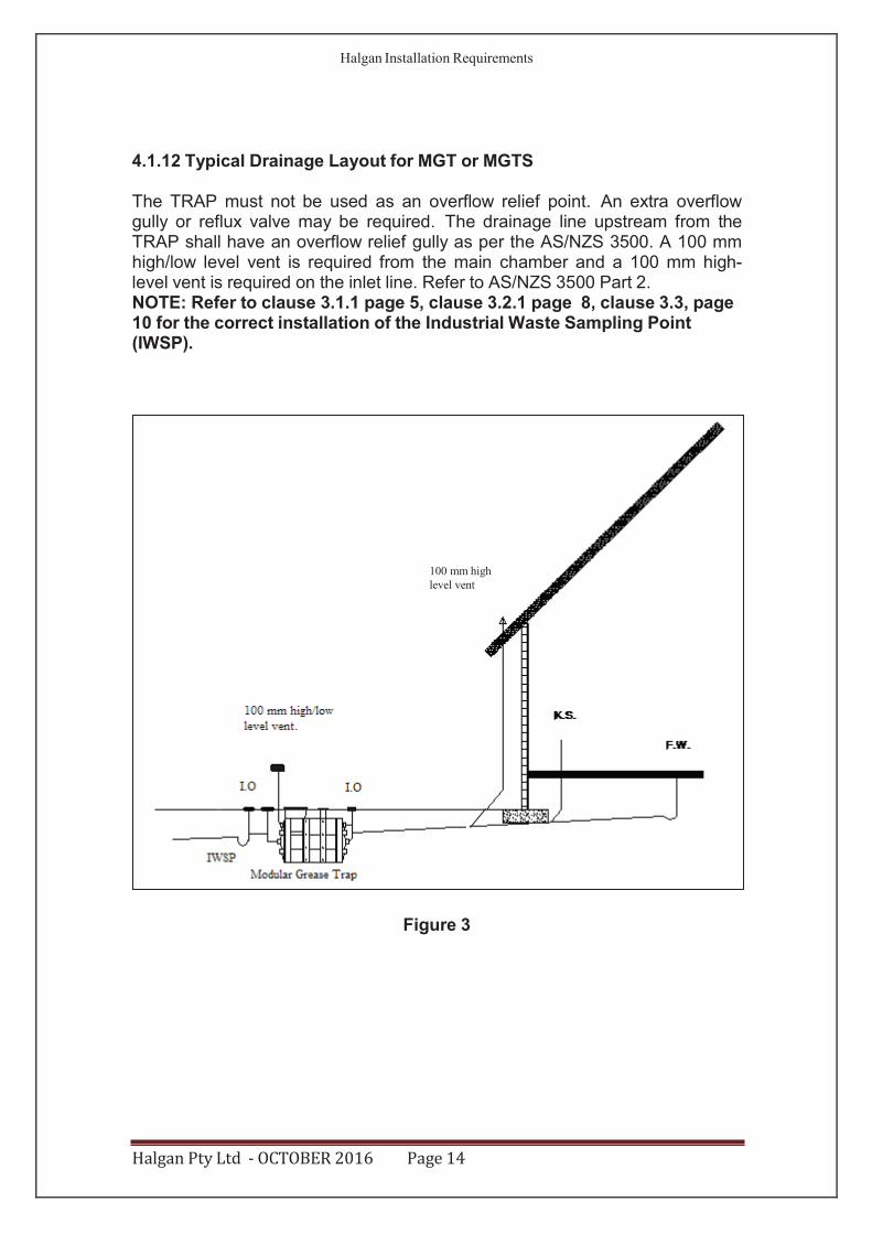
4.1.12 Typical Drainage Layout for MGT or MGTS
The TRAP must not be used as an overflow relief point. An extra overflow gully or reflux valve may be required. The drainage line upstream from the TRAP shall have an overflow relief gully as per the AS/NZS 3500. A 100 mm high/low level vent is required from the main chamber and a 100 mm high- level vent is required on the inlet line. Refer to AS/NZS 3500 Part 2. NOTE: Refer to clause 3.1.1 page 5, clause 3.2.1 page 8, clause 3.3, page 10 for the correct installation of the Industrial Waste Sampling Point (IWSP).
Figure 3
Halgan Pty Ltd - OCTOBER 2016 Page 14
100 mm high level vent
Halgan Installation Requirements
4.2 Installation Requirements Modular Grease Trap - MGT
4.2.1 General
The TRAP is to be installed in a location that will not cause a nuisance, obstruct fire access, cannot be vandalised or be damaged by vehicles. The TRAP must have ease of access to pumpout point for maintenance. A hose tap fitted with a Back Flow Protection Device (as per AS/NZS 3500) must be provided within 6 m of the TRAP for cleaning purposes.
4.2.2 Installation Above Ground
4.2.2.1 Installation above ground MGT
The MGT is to be supported on a 100 mm thick concrete pad or on 98% compacted level ground with 20 mm sand base. The TRAP does not require a stand. All pipes connecting to the TRAP shall be fully supported; there should be no stress on the tank connections. All storm water must be diverted away from TRAP to prevent undermining of supports or foundations.
4.2.2.2 Installation above ground MGTS Series
The MGTS DOES require a stand and is to be supported on a 100 mm thick concrete pad or on 98% compacted level ground with 20 mm sand base. All pipes connecting to the TRAP shall be fully supported; there should be no stress on the tank connections. All storm water must be diverted away from TRAP to prevent undermining of supports or foundations. Screw Type Polypropylene lids must be installed for all Above Ground Installations.
4.2.3 Installation below ground MGT/MGTS
All connections to the Trap shall be in accordance with the appropriate authorities. Any excavation exceeding 1.5 m in depth shall comply with the construction safety Acts and Regulations. Before backfilling, the Modular Grease Trap must be filled with water. NOTE: In the Water Corporation area, maximum of 900 mm extension riser for the access lid can be used.
4.2.3.1 Excavation dimensions
The excavated hole width shall be kept as narrow as practicable. The depth shall be not greater than 150 mm than the required depth. A 75 mm clearance is required at the sides of tank.
4.2.3.2 Over excavation
Where an excavation has been deeper than necessary, the excess depth shall be filled either with bedding material compacted to achieve a compaction of 98% or concrete.
Halgan Pty Ltd - OCTOBER 2016 Page 15
Halgan Installation Requirements
4.2.3.3 Installation in mine subsidence, filled, unstable or water charged areas
A qualified engineer is required to certify this application.
4.2.3.4 Backfill/Bedding
4.2.3.4.1 Backfill/Bedding material MGT
The backfill/bedding material shall be 1 part Portland cement to 5 parts clean sand. The backfill/bedding shall be thoroughly compacted by tampering at 300 mm layers. The backfill/bedding material shall encase the whole tank.
4.2.3.4.2 Backfill/Bedding material MGTS Series
The bedding material shall be granular material up 10 mm. The bedding shall be thoroughly compacted by tampering at 300 mm layers. The bedding material shall encase the whole tank.
Halgan Pty Ltd - OCTOBER 2016 Page 16
Halgan Installation Requirements
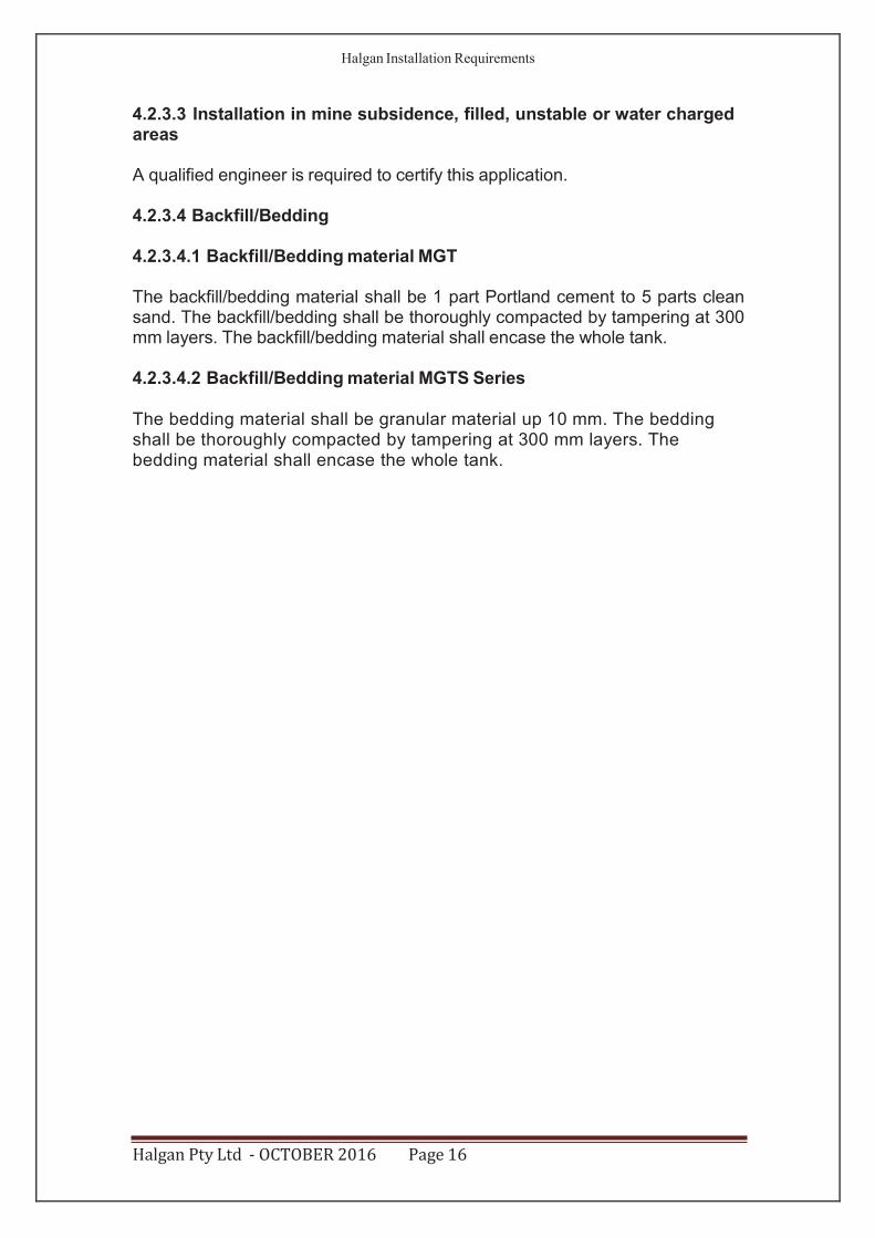
4.2.3.5 Final Backfill
The final backfill material shall comply with the following:
(a) Spoil from the excavation of the trench may be used. (b) Foreign material such as builder's waste, bricks, and concrete shall not be used. (c) The backfill shall be compacted to restore the excavated hole as near as practicable to the normal ground.
4.2.4 Relief Overflow Point The TRAP is not to be used as a surcharge point. An extra surcharge gully may be required or a reflux valve installed. Refer to figure in AS/NZS 3500 Part 2. The drainage line upstream from the TRAP shall have an overflow relief gully as per the AS/NZS 3500.
4.2.5 Protection Barricades The protection barricades shall be installed to protect the TRAP from physical damage. The posts shall be manufactured from 80 mm galvanised tube (refer to material specification) with a sealing cap at the top. A 400 mm white strip shall be painted at the top of the post. The posts will be 1300 mm long and approximately 800 mm apart.
4.2.5.1 Concrete Installation The post shall be 1300 mm long with a 200 mm x 200 mm base plate fixed to the concrete with four 12 mm x 50 mm concrete anchors.
4.2.5.2 Installation in Bitumen & In Ground A hole shall be excavated 400 mm x 400 mm x 400 mm deep. The base shall be encased in concrete. The post will be 1700 mm long and have bituminous
Halgan Pty Ltd - OCTOBER 2016 Page 17
Halgan Installation Requirements
paint applied to the section enclosed in concrete. The concrete shall be finished in a way that water cannot settle around the base.
4.2.6 Venting
The high level vent on the inlet line shall be 100 mm. The high level vent shall terminate above the roofline and a high/low vent from the chamber as per AS/NZS 3500. Refer to AS/NZS 3500 Part 2. Air admittance valves are NOT TO BE USED in any part of the venting in the installation of the TRAP.
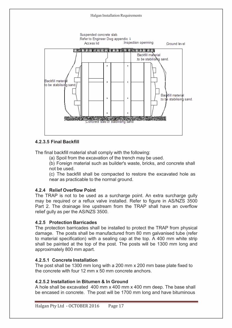
4.2.7 Pipe Connection Inlet connection is a double Y junction (figure 1) or in some council areas a 90 degree slope junction (figure 2) is allowed. The top connection of the TRAP is the vent transfer to high-level vent of the inlet drainage line. The middle connection of the TRAP is the liquid connection. The outlet connection is raised and the chamber vent at the outlet side is terminated as a low or high- level vent. Check council requirements.
Figure 1 Figure 2 4.2.7.1 Series Connection In series connections the top vent transfer pipe and the middle transfer pipe are connected to the next vessel.
IWSP
Halgan Pty Ltd - OCTOBER 2016 Page 18
IWSP
IWSP
Vent transfer pipe
Liquid transfer pipe
Halgan Installation Requirements
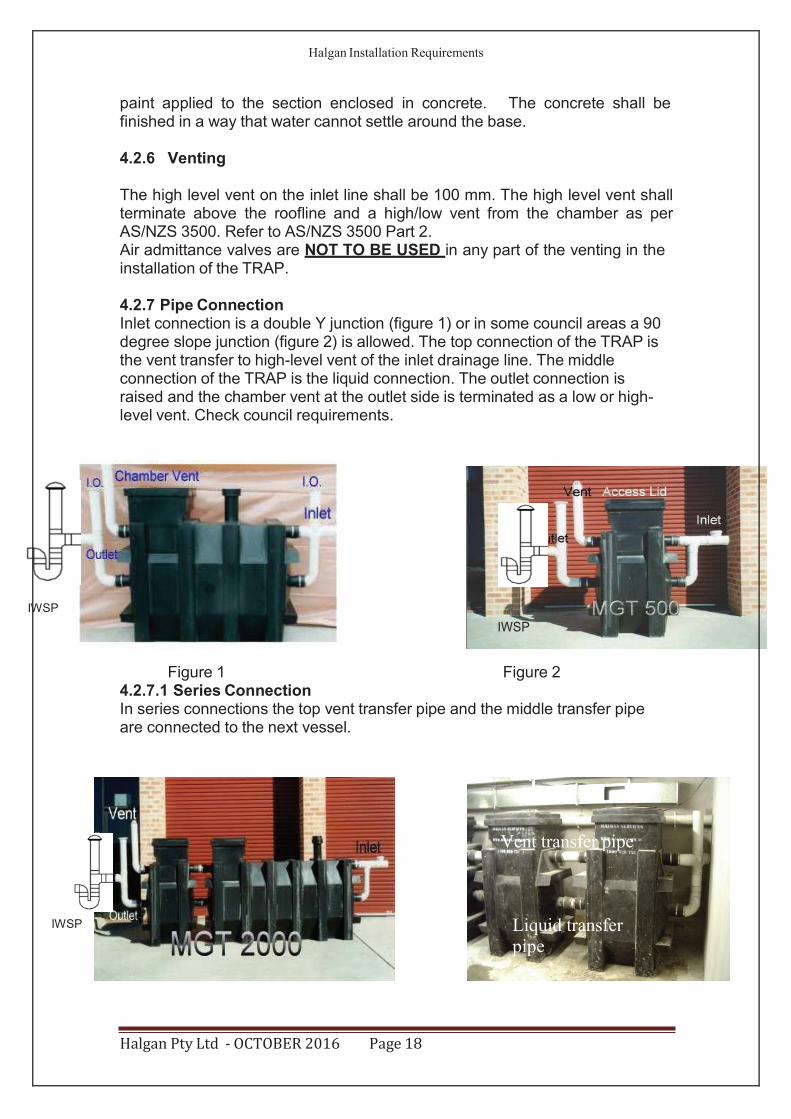
4.2.7.2 Parallel Connections When the TRAP is installed parallel, the vent and liquid transfer pipes are connected as shown in figure 3 & 4.
Figure 3 Figure 4
4.2.8 Vacuum Pumpout Line (optional extra)
Note: Consult with pump out contractor and Customer Service Representative for correct location. The vacuum pump out line is used by the cleaning contractor to pump out the TRAP in restricted site applications. A 50 mm M.I. quick release coupling with dust caps is supplied with the unit. The vacuum line has to be extended to the external of the building for ease of access. The lines must be as straight and short as possible. Where bends are necessary, only long radius bends should be used. The size of the vacuum line pipe can be 50 mm for the first 6 metres and 80 mm thereafter. For the “S” series Halgan can provided an Optional Extra 80 mm connection point. The piping and fittings material can either be class 12 pressure pipe or galvanised pipe (refer to material specification). A 600 mm long x 600 mm wide x 200 mm deep access area is required around the quick release coupling for ease of connection.
4.2.9 Access Lids (refer to Engineers drawing appendix 1)
General - The top of the access lid shall be a 100 mm above ground level to stop the ingress of storm water. The polyethylene TRAP with the polypropylene lid can be installed in a non trafficable areas, eg garden beds etc. If the TRAP is in a location where it can be damaged due to gardening activities (lawn mower etc) a minimum 100 mm x 100 mm concrete edge strip is to be installed around the TRAP. NOTE: In the Water Corporation area, maximum of 900 mm extension riser for the access lid can be used. Duty of Access Lids - All covers are manufactured to Australian Standards 3906 and comply with the required design loading.
Halgan Pty Ltd - OCTOBER 2016 Page 19
Vent transfer
Liquid transfer
Halgan Installation Requirements
For above ground or non-pedestrian application the access lid is 600 mm in diameter and manufactured from high density polyethylene lid. All other application the access lid shall be 600 x 600 square, cast iron, gas tight, concrete infill lid and frame. For concrete lid requirements for the Modular Grease Trap access lid and ports, refer to appendix 1. All handles are as per Water Corporation requirements 1999.
4.2.10 Installation Access Covers and Grating In-situ concrete method
4.2.10.1 Introduction
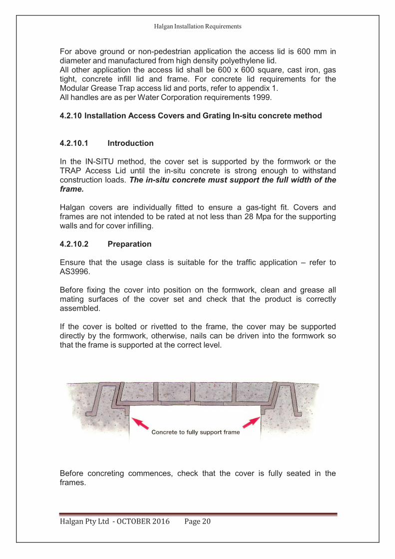
In the IN-SITU method, the cover set is supported by the formwork or the TRAP Access Lid until the in-situ concrete is strong enough to withstand construction loads. The in-situ concrete must support the full width of the frame.
Halgan covers are individually fitted to ensure a gas-tight fit. Covers and frames are not intended to be rated at not less than 28 Mpa for the supporting walls and for cover infilling.
4.2.10.2 Preparation
Ensure that the usage class is suitable for the traffic application – refer to AS3996.
Before fixing the cover into position on the formwork, clean and grease all mating surfaces of the cover set and check that the product is correctly assembled.
If the cover is bolted or rivetted to the frame, the cover may be supported directly by the formwork, otherwise, nails can be driven into the formwork so that the frame is supported at the correct level.
Before concreting commences, check that the cover is fully seated in the frames.
Halgan Pty Ltd - OCTOBER 2016 Page 20
Halgan Installation Requirements
If the cover was fitted by installation bolts, these will have to be removed prior to the infilling covers. This means that infilling will have to be delayed until the concrete supporting the frame has cured.
4.2.10.3 Concreting
Place the concrete in-situ and vibrate well so that the concrete which supports the full width of the frame and fills the frame cells is well compacted and will reach the specified Mpa. Honeycombed or bony concrete under the frame will reduce the capacity of the cover and may cause it to fail at relatively low loads. If infill covers are supplied the concrete infilling is at the same time.
Screed off the excess concrete and finish the surface as required. The ribs and edges of the cover and frame should be visible.
Allow the concrete to cure before removing the cover and the formwork – premature stripping may damage the supporting concrete and distort the frame.
After the concrete has cured, remove the cover, mark the pit number on the underside of the cover (do not mix the covers) and strip the formwork.
Clean and grease all mating surfaces of the cover and frame before replacing the cover.
Where grating is being installed, references to infilling the cover should be ignored. Inadequate installation will void product warranty.
5.0 Vented Chambers
Refer to AS/NZS 3500.
Halgan Pty Ltd - OCTOBER 2016 Page 21

Halgan Installation Requirements
6.0 Warranty Card
HALGAN PTY LTD, UNIT 2 187 South Creek Road Cromer NSW 2099 Phone: 02 9972 1355 Fax: 02 9972 1455 Modular Grease Trap warranty card to be completed and returned to Halgan Pty Ltd. PRODUCT WARRANTY REGISTRATION CARD NAME: ADDRESS: TYPE OF BUSINESS: NAME OF PURCHASING AGENT: AGENT ADDRESS: DATE OF PURCHASE: PRODUCT MODEL NO.:
CONDITIONS OF WARRANTY
Halgan Pty Ltd warrants that all Halgan products are free from defects. Any apparent fault will be rectify free of charge by Halgan Pty Ltd or by any of Halgan's authorised agents within appropriate time limits herein set out provided that * The customer produces the original invoice or other purchase document as proof of the purchase date. * All costs of installation, cartage, freight, travelling expenses and insurance are paid by the claimant. * Halgan Pty Ltd and its Authorised Dealers will not be liable for any consequential loss or damage whatsoever or howsoever arisen. * The Product being precision equipment has not been misused, adjusted or serviced by any person other than a service dealer, authorised by Halgan Pty Ltd. * The equipment has been installed correctly and is used in accordance with the Halgan Pty Ltd specifications issued with the product. * Nothing in these Conditions of Warranty shall be deemed to restrict any warranty required to be given under the
Trade Practices Act (Commonwealth) or any consumer legislation of any State of Australia.
12 MONTH WARRANTY
* Full warranty on mechanical and electrical components. Electronic circuitry issued with a letter of acceptance from Electrical Supply Authority.
7 YEAR WARRANTY
*Full warranty on polyethylene tanks.
WARRANTY EXCLUSIONS
* Normal user adjustments or customers instruction on the Product's operation. * Products purchased overseas / interstate - not designed or approved in the installed area. * Normal user adjustments or customer instruction on the Product's operation. * Abnormal product performance caused by any ancillary equipment, interference or other external factors. * Cleaning of the product and filters. *Any mileage or travelling charges outside the Service Dealer’s normal service area
Halgan Pty Ltd - OCTOBER 2016 Page 22
Halgan Installation Requirements
7.0 Maintenance
7.1 Maintenance Frequency Any TRAP installed internally or at a location where it might cause an objection on health grounds must be on a maximum pump out frequency of eight weeks or less. In all other applications, the TRAP will be pumped out at a maximum of 3 months or when a floating layer of 75 mm grease has formed on the surface. In all locations, Water Corporation sets the clean out schedule. Note: The pump out frequency will depend on the house keeping within the premises.
7.2 Records The customer shall keep, and make available, records pertaining to clean outs as specified in permit to discharge.
7.3 On-Site Cleaning Procedures
7.3.1 Modular Grease Trap (MGT) The TRAP installation must be maintained as follows:
∙ Clean outs must be undertaken by approved waste collection contractor
∙ The contractor should make a visual observation every time they clean the TRAP to make sure it is on the correct maintenance frequency. The trade waste customer will have to be notified. Water Corporation will determine the pump out frequency.
∙ Remove all the TRAP access lids and access port lids, from the traps. Insert the vacuum hose into the 100 mm SCD servicing pipe in the downstream TRAP unit. Turn the vacuum pump on for 5 seconds. Insert the vacuum hose into the access port (access lid for MGTS series) of the upstream TRAP unit and remove the greasy liquid waste from the TRAP. If access is available turn the kitchen taps on to flush out the drainage line and help the cleaning process. Then insert the vacuum hose into access lid and remove any residual liquid waste. Repeat Step 3 and Step 4 in the remaining TRAP units working downstream. Then use the designated hose tap to connect the hose for cleaning of the Modular Grease Trap. At this time, hose down the SCD unit. Check the security of the SCD unit. Replace access lids and complete the appropriate servicing documents.
∙ If the plates from the SCD are damaged in any way then the SCD must be repaired or replaced immediately. If the connection of SCD has been broken or other plumbing connections have failed then these must be replaced immediately. The waste contractor should note on their clearance reports any damaged and failure of the SCD and plumbing pipework connecting the SCD.
Halgan Pty Ltd - OCTOBER 2016 Page 23
Halgan Installation Requirements
Halgan Pty Ltd - OCTOBER 2016 Page 24
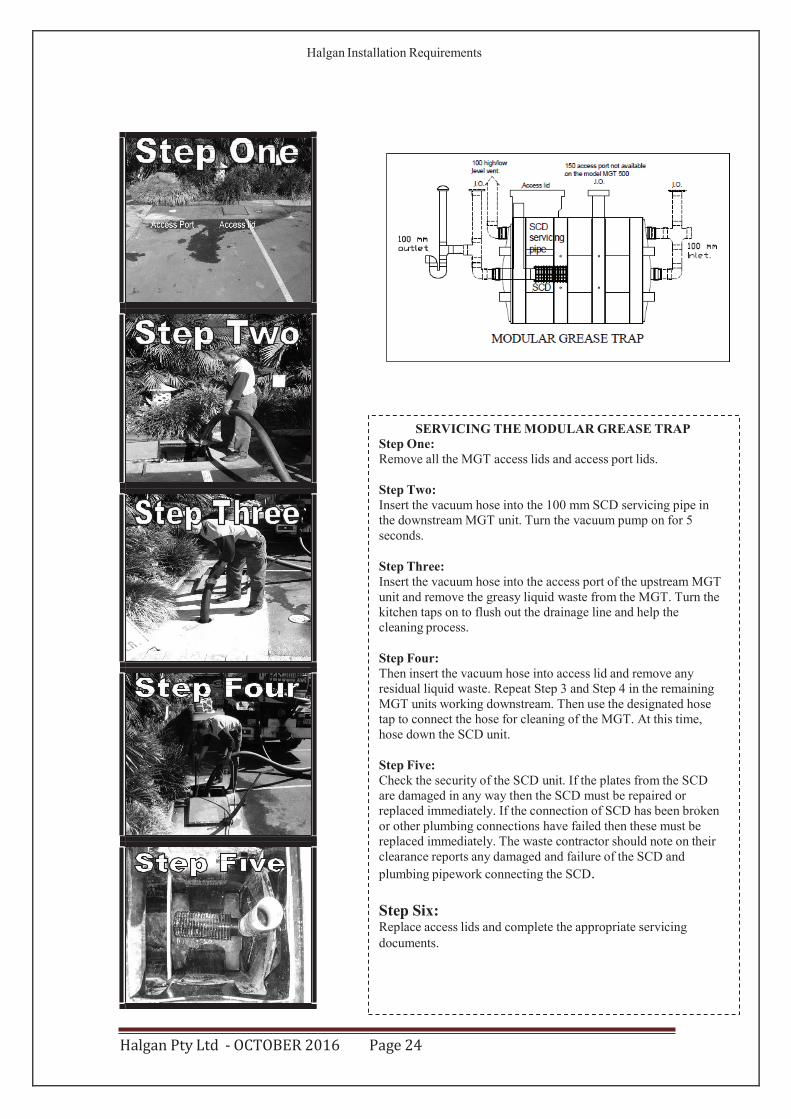
SERVICING THE MODULAR GREASE TRAP Step One: Remove all the MGT access lids and access port lids.
Step Two: Insert the vacuum hose into the 100 mm SCD servicing pipe in the downstream MGT unit. Turn the vacuum pump on for 5 seconds.
Step Three: Insert the vacuum hose into the access port of the upstream MGT unit and remove the greasy liquid waste from the MGT. Turn the kitchen taps on to flush out the drainage line and help the cleaning process.
Step Four: Then insert the vacuum hose into access lid and remove any residual liquid waste. Repeat Step 3 and Step 4 in the remaining MGT units working downstream. Then use the designated hose tap to connect the hose for cleaning of the MGT. At this time, hose down the SCD unit.
Step Five: Check the security of the SCD unit. If the plates from the SCD are damaged in any way then the SCD must be repaired or replaced immediately. If the connection of SCD has been broken or other plumbing connections have failed then these must be replaced immediately. The waste contractor should note on their clearance reports any damaged and failure of the SCD and plumbing pipework connecting the SCD.
Step Six: Replace access lids and complete the appropriate servicing documents.
Halgan Installation Requirements
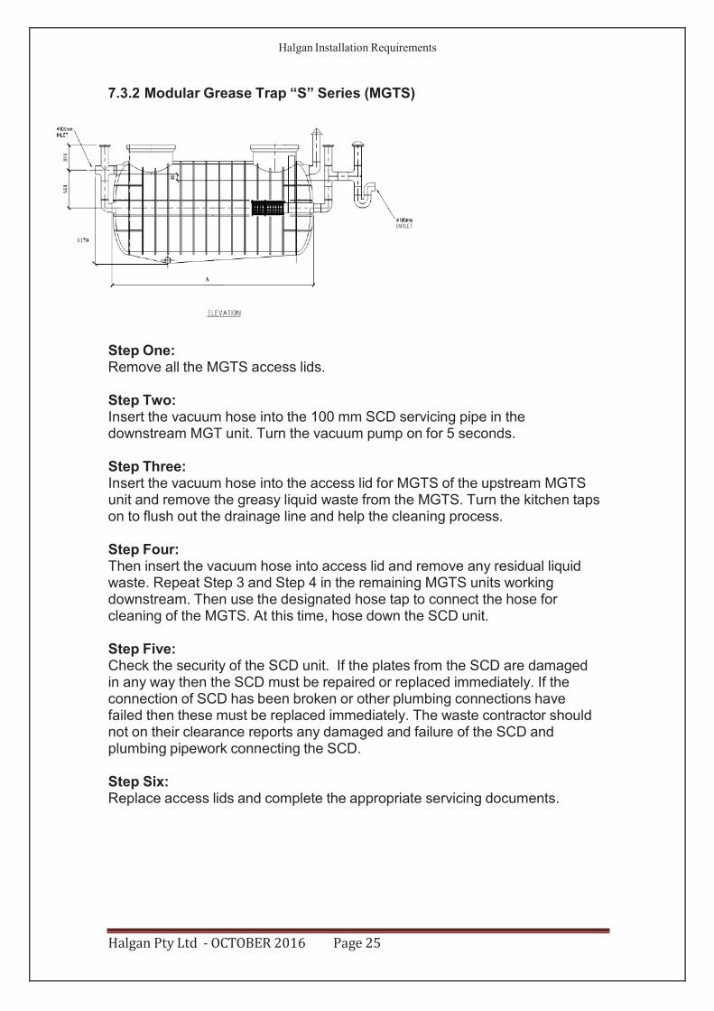
7.3.2 Modular Grease Trap “S” Series (MGTS)
Step One: Remove all the MGTS access lids.
Step Two: Insert the vacuum hose into the 100 mm SCD servicing pipe in the downstream MGT unit. Turn the vacuum pump on for 5 seconds.
Step Three: Insert the vacuum hose into the access lid for MGTS of the upstream MGTS unit and remove the greasy liquid waste from the MGTS. Turn the kitchen taps on to flush out the drainage line and help the cleaning process.
Step Four: Then insert the vacuum hose into access lid and remove any residual liquid waste. Repeat Step 3 and Step 4 in the remaining MGTS units working downstream. Then use the designated hose tap to connect the hose for cleaning of the MGTS. At this time, hose down the SCD unit.
Step Five: Check the security of the SCD unit. If the plates from the SCD are damaged in any way then the SCD must be repaired or replaced immediately. If the connection of SCD has been broken or other plumbing connections have failed then these must be replaced immediately. The waste contractor should not on their clearance reports any damaged and failure of the SCD and plumbing pipework connecting the SCD.
Step Six: Replace access lids and complete the appropriate servicing documents.
Halgan Pty Ltd - OCTOBER 2016 Page 25
Halgan Installation Requirements
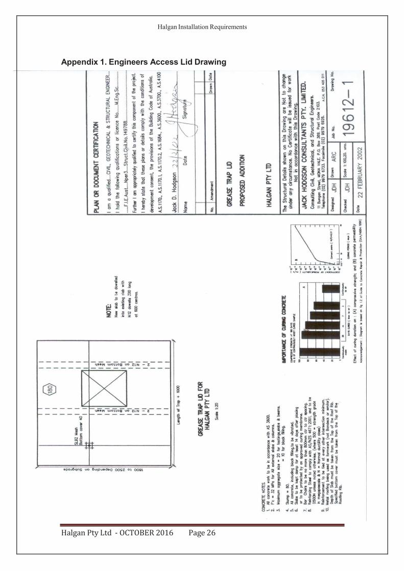
Appendix 1. Engineers Access Lid Drawing
Halgan Pty Ltd - OCTOBER 2016 Page 26
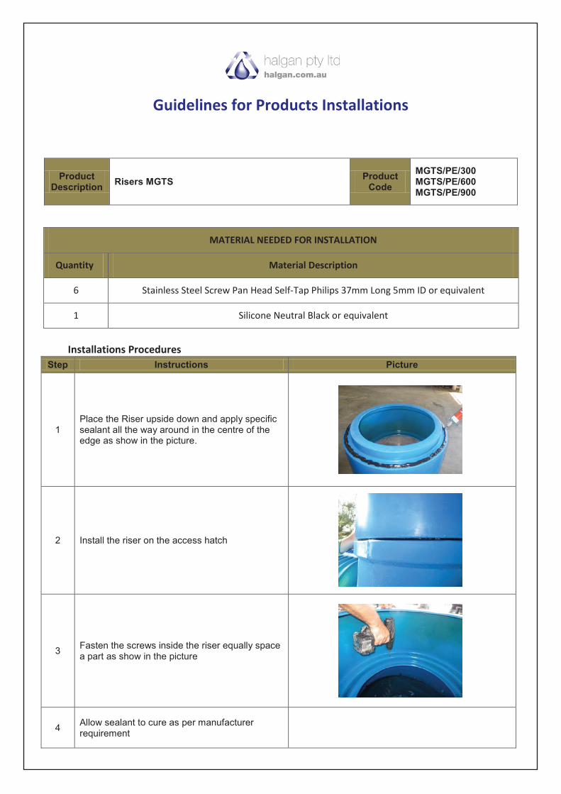
Guidelines for Products Installations
MATERIAL NEEDED FOR INSTALLATION
Quantity Material Description
6 Stainless Steel Screw Pan Head Self-Tap Philips 37mm Long 5mm ID or equivalent
1 Silicone Neutral Black or equivalent
Installations Procedures
Step Instructions Picture
1Place the Riser upside down and apply specific sealant all the way around in the centre of the edge as show in the picture.
2 Install the riser on the access hatch
3Fasten the screws inside the riser equally space a part as show in the picture
4Allow sealant to cure as per manufacturer requirement
Product Description
Risers MGTSProduct
Code
MGTS/PE/300 MGTS/PE/600MGTS/PE/900