Embed Size (px)
Citation preview

Modified Steel-Jacketed Columns for Combined Blast andSeismic Retrofit of Existing Bridge ColumnsPierre Fouch�e1; Michel Bruneau, F.ASCE2; and Vincent P. Chiarito, M.ASCE3
Abstract: Steel jacketing has been used extensively in the United States to retrofit seismically deficient bridge columns. This procedure,which consists of encasing a RC column in a steel jacket, is effective in providing a ductile seismic response but does not enhance the blast re-sistance of the column. This is because a gap is typically left at the top and bottom of the jacket to prevent increased flexural strength, such asto avoid undesirable overload of the footing or cap beam. Blast tests have demonstrated that direct shear failure can develop at these gap loca-tions. A modification to steel-jacketed columns is proposed here to provide an added blast resistance. It consists of structural steel collarsplaced around the gaps and tied to the adjacent elements with postinstalled anchors. Blast tests were conducted to investigate the effectivenessof this simple proposed detail. Experimental results indicated that the concept was effective in preventing direct shear failure. Severe blastload demands were applied to investigate the behavior of the retrofitted column under extreme ductility demands. All specimens exhibited sat-isfactory ductile behavior, except one, which uncharacteristically failed due to fracture of the tube’s vertical weld seam. DOI: 10.1061/(ASCE)BE.1943-5592.0000882.© 2016 American Society of Civil Engineers.
Author keywords: Jacketed column; Retrofit; Blast testing; Inelastic response; Direct shear; Plastic hinging.
Introduction
In many parts of the United States, particularly in California, rein-forcement detailing requirements in effect decades ago resulted inRC bridge columns that exhibited nonductile behavior duringearthquakes (Housner and Thiel 1990). Many methods have beenused to retrofit such nonductile columns (Priestley et al. 1996).One of the most popular methods, steel jacketing, has been com-monly used across the United States (Priestley et al. 1994; Chai1996; Shams and Saadeghvaziri 1997; Kim and Shinozuka 2004).A steel-jacketed column (SJC) is created by adding a steel shellthat provides confinement to the concrete. This steel jacket allowsplastic hinges to develop at the top and bottom of the column,where plastic hinges would be unable to form in a nonductile col-umn without adequate transverse reinforcement.A column retrofitted with a steel jacket may visually resemble a
concrete-filled steel tube composite column, but it does not behavesimilarly because the jacket is typically discontinuous at the columntop and base to avoid undesirable overload of the adjacent members(i.e., footing or cap beam) due to composite action that would sig-nificantly increase the flexural strength of the column (Buckle et al.2006). As a result, although wrapping a concrete column with asteel jacket is widely accepted as a cost-effective retrofit technique
for columns of seismically deficient bridges, the merits of this tech-nique do not translate into improved blast performance for bridgecolumns. In tests performed by Fujikura et al. (2008) and Fujikuraand Bruneau (2011), direct shear failure under blast load wasobserved at the gaps between the jacket and the surrounding footingwhen exposed to blast, and analyses have supported this observa-tion (Fujikura and Bruneau 2012).To prevent this undesirable failure mode without hindering the
initial role of the jacket, the use of structural steel collars placedaround the gaps and tied to the adjacent elements with postinstalledanchors as a technique to increase shear strength locally was pro-posed. A nonstick interface material inserted between the collar andthe column allows smooth contact, thus increasing only shearstrength while leaving flexural strength of the column virtuallyunchanged (as intended by the initial jacketing design). This con-cept is referred to here as a modified SJC (MSJC). This paper docu-ments the results of blast tests conducted to investigate the effec-tiveness of this proposed MSJC system (Fouch�e and Bruneau2014). Furthermore, because it is customary in blast engineeringpapers not to report charge weights and standoff distances, shortingpins were used to calculate specimen velocity to provide data thatcan be used by the broader research community in future analyticalwork. The resulting impulses calculated from those measuredvelocities are presented in the last section of this paper.
SpecimenDesign and Experimental Setups
Specimens were quarter scale of prototype columns in multicolumnbridge pier bents, part of a typical three-span continuous highwaybridge (prototype span lengths of 35, 25, and 30 m). Note that scaletesting has gained substantial acceptance in blast engineering overthe past decade and was proven to provide reliable results and keyknowledge in understanding the behavior of structures subjected toblast (Woodson and Baylot 1999; Williams et al. 2008; J. Ray, per-sonal communication, 2008). The work conducted here was per-formed with the same mindset. Future research at larger scales for
1Consultant, Haiti; formerly, Graduate Research Assistant, Dept. ofCivil, Structural, and Environmental Engineering, Univ. at Buffalo,Buffalo, NY 14260.
2Professor, Dept. of Civil, Structural, and Environmental Engineering,Univ. at Buffalo, Buffalo, NY 14260 (corresponding author). E-mail:[email protected]
3Research Structural Engineer, CEERD-GSS, 3909 Halls Ferry Rd.,U.S. Army Engineer Research and Development Center, Vicksburg, MS39180-6199.Note. This manuscript was submitted on June 1, 2015; approved on
October 21, 2015; published online on February 11, 2016. Discussion pe-riod open until July 11, 2016; separate discussions must be submitted forindividual papers. This paper is part of the Journal of BridgeEngineering, © ASCE, ISSN 1084-0702.
© ASCE 04016035-1 J. Bridge Eng.
J. Bridge Eng., 2016, 21(7): 04016035
yg
yy
()
pyg
py
g
the same scaled distance could further validate the findings pre-sented here.For consistency in comparing results, the jacketed columns
(prior to adding the blast retrofit collars) were designed and built tobe identical to those used in prior blast tests in which direct shearfailure was observed (Fujikura and Bruneau 2011). Specimens con-sisted of nonductile RC columns retrofitted by adding a steel shellthat provides confinement to the concrete and allows plastic hingesto develop at the top and bottom of the column.The 1,500-mm (65-in.) tall nonductile RC column specimens all
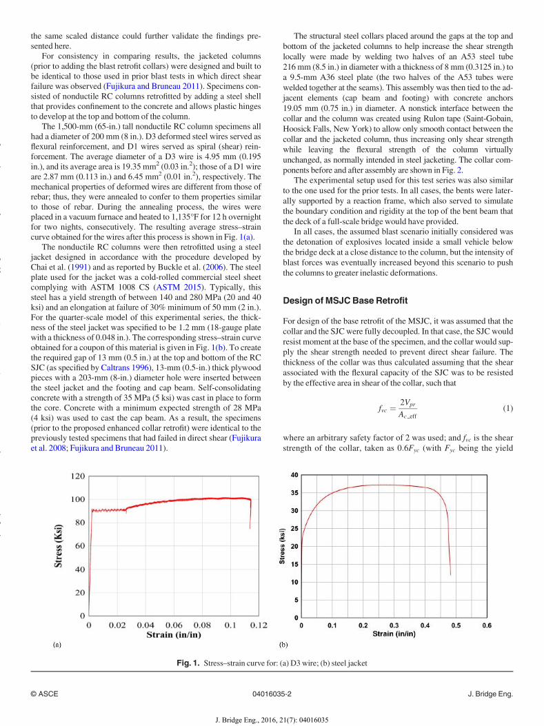
had a diameter of 200 mm (8 in.). D3 deformed steel wires served asflexural reinforcement, and D1 wires served as spiral (shear) rein-forcement. The average diameter of a D3 wire is 4.95 mm (0.195in.), and its average area is 19.35 mm2 (0.03 in.2); those of a D1 wireare 2.87 mm (0.113 in.) and 6.45 mm2 (0.01 in.2), respectively. Themechanical properties of deformed wires are different from those ofrebar; thus, they were annealed to confer to them properties similarto those of rebar. During the annealing process, the wires wereplaced in a vacuum furnace and heated to 1,135°F for 12 h overnightfor two nights, consecutively. The resulting average stress–straincurve obtained for the wires after this process is shown in Fig. 1(a).The nonductile RC columns were then retrofitted using a steel
jacket designed in accordance with the procedure developed byChai et al. (1991) and as reported by Buckle et al. (2006). The steelplate used for the jacket was a cold-rolled commercial steel sheetcomplying with ASTM 1008 CS (ASTM 2015). Typically, thissteel has a yield strength of between 140 and 280 MPa (20 and 40ksi) and an elongation at failure of 30%minimum of 50 mm (2 in.).For the quarter-scale model of this experimental series, the thick-ness of the steel jacket was specified to be 1.2 mm (18-gauge platewith a thickness of 0.048 in.). The corresponding stress–strain curveobtained for a coupon of this material is given in Fig. 1(b). To createthe required gap of 13 mm (0.5 in.) at the top and bottom of the RCSJC (as specified by Caltrans 1996), 13-mm (0.5-in.) thick plywoodpieces with a 203-mm (8-in.) diameter hole were inserted betweenthe steel jacket and the footing and cap beam. Self-consolidatingconcrete with a strength of 35 MPa (5 ksi) was cast in place to formthe core. Concrete with a minimum expected strength of 28 MPa(4 ksi) was used to cast the cap beam. As a result, the specimens(prior to the proposed enhanced collar retrofit) were identical to thepreviously tested specimens that had failed in direct shear (Fujikuraet al. 2008; Fujikura and Bruneau 2011).
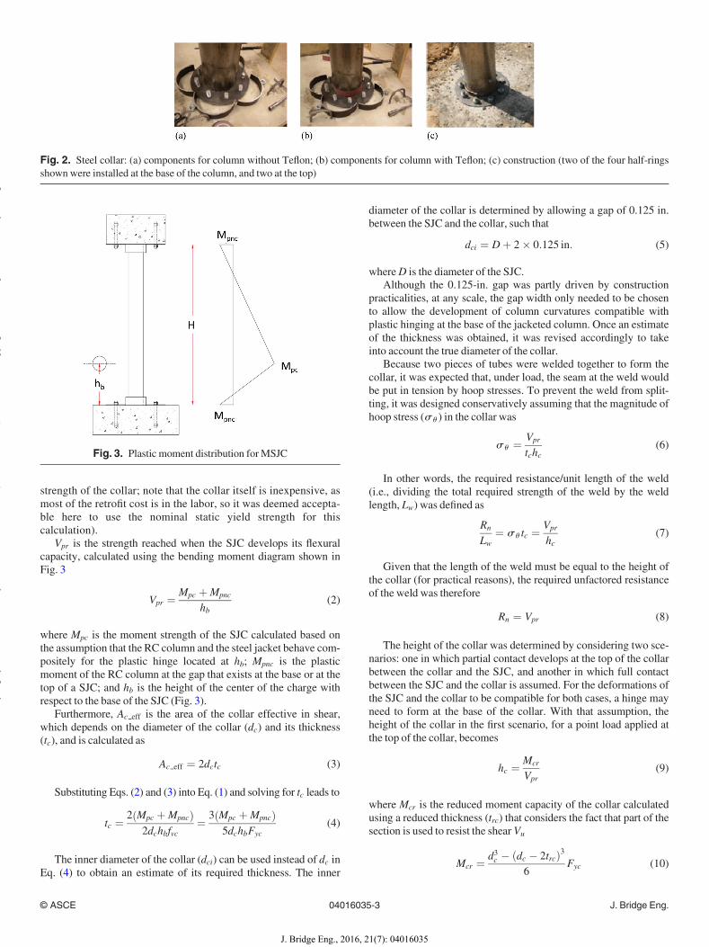
The structural steel collars placed around the gaps at the top andbottom of the jacketed columns to help increase the shear strengthlocally were made by welding two halves of an A53 steel tube216 mm (8.5 in.) in diameter with a thickness of 8 mm (0.3125 in.) toa 9.5-mm A36 steel plate (the two halves of the A53 tubes werewelded together at the seams). This assembly was then tied to the ad-jacent elements (cap beam and footing) with concrete anchors19.05 mm (0.75 in.) in diameter. A nonstick interface between thecollar and the column was created using Rulon tape (Saint-Gobain,Hoosick Falls, New York) to allow only smooth contact between thecollar and the jacketed column, thus increasing only shear strengthwhile leaving the flexural strength of the column virtuallyunchanged, as normally intended in steel jacketing. The collar com-ponents before and after assembly are shown in Fig. 2.The experimental setup used for this test series was also similar
to the one used for the prior tests. In all cases, the bents were later-ally supported by a reaction frame, which also served to simulatethe boundary condition and rigidity at the top of the bent beam thatthe deck of a full-scale bridge would have provided.In all cases, the assumed blast scenario initially considered was
the detonation of explosives located inside a small vehicle belowthe bridge deck at a close distance to the column, but the intensity ofblast forces was eventually increased beyond this scenario to pushthe columns to greater inelastic deformations.
Design of MSJCBase Retrofit
For design of the base retrofit of the MSJC, it was assumed that thecollar and the SJCwere fully decoupled. In that case, the SJCwouldresist moment at the base of the specimen, and the collar would sup-ply the shear strength needed to prevent direct shear failure. Thethickness of the collar was thus calculated assuming that the shearassociated with the flexural capacity of the SJC was to be resistedby the effective area in shear of the collar, such that
fvc ¼ 2Vpr
Ac eff(1)
where an arbitrary safety factor of 2 was used; and fvc is the shearstrength of the collar, taken as 0:6Fyc (with Fyc being the yield
Fig. 1. Stress–strain curve for: (a) D3 wire; (b) steel jacket
© ASCE 04016035-2 J. Bridge Eng.
J. Bridge Eng., 2016, 21(7): 04016035
yg
yy
()
pyg
py
g
strength of the collar; note that the collar itself is inexpensive, asmost of the retrofit cost is in the labor, so it was deemed accepta-ble here to use the nominal static yield strength for thiscalculation).
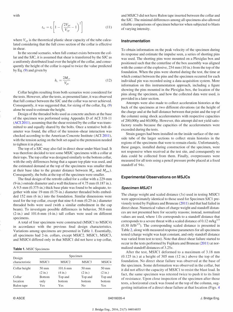
Vpr is the strength reached when the SJC develops its flexuralcapacity, calculated using the bending moment diagram shown inFig. 3
Vpr ¼ Mpc þMpnc
hb(2)
where Mpc is the moment strength of the SJC calculated based onthe assumption that the RC column and the steel jacket behave com-positely for the plastic hinge located at hb; Mpnc is the plasticmoment of the RC column at the gap that exists at the base or at thetop of a SJC; and hb is the height of the center of the charge withrespect to the base of the SJC (Fig. 3).Furthermore, Ac eff is the area of the collar effective in shear,
which depends on the diameter of the collar (dc) and its thickness(tc), and is calculated as
Ac eff ¼ 2dctc (3)
Substituting Eqs. (2) and (3) into Eq. (1) and solving for tc leads to
tc ¼ 2 Mpc þMpncð Þ2dchbfvc
¼ 3 Mpc þMpncð Þ5dchbFyc
(4)
The inner diameter of the collar (dci) can be used instead of dc inEq. (4) to obtain an estimate of its required thickness. The inner
diameter of the collar is determined by allowing a gap of 0.125 in.between the SJC and the collar, such that
dci ¼ Dþ 2� 0:125 in: (5)
whereD is the diameter of the SJC.Although the 0.125-in. gap was partly driven by construction
practicalities, at any scale, the gap width only needed to be chosento allow the development of column curvatures compatible withplastic hinging at the base of the jacketed column. Once an estimateof the thickness was obtained, it was revised accordingly to takeinto account the true diameter of the collar.Because two pieces of tubes were welded together to form the
collar, it was expected that, under load, the seam at the weld wouldbe put in tension by hoop stresses. To prevent the weld from split-ting, it was designed conservatively assuming that the magnitude ofhoop stress (su ) in the collar was
su ¼ Vpr
tchc(6)
In other words, the required resistance/unit length of the weld(i.e., dividing the total required strength of the weld by the weldlength, Lw) was defined as
Rn
Lw¼ su tc ¼ Vpr
hc(7)
Given that the length of the weld must be equal to the height ofthe collar (for practical reasons), the required unfactored resistanceof the weld was therefore
Rn ¼ Vpr (8)
The height of the collar was determined by considering two sce-narios: one in which partial contact develops at the top of the collarbetween the collar and the SJC, and another in which full contactbetween the SJC and the collar is assumed. For the deformations ofthe SJC and the collar to be compatible for both cases, a hinge mayneed to form at the base of the collar. With that assumption, theheight of the collar in the first scenario, for a point load applied atthe top of the collar, becomes
hc ¼ Mcr
Vpr(9)
where Mcr is the reduced moment capacity of the collar calculatedusing a reduced thickness (trc) that considers the fact that part of thesection is used to resist the shear Vu
Mcr ¼ d3c � dc � 2trcð Þ36
Fyc (10)
Fig. 2. Steel collar: (a) components for column without Teflon; (b) components for column with Teflon; (c) construction (two of the four half-ringsshownwere installed at the base of the column, and two at the top)
Fig. 3. Plastic moment distribution forMSJC
© ASCE 04016035-3 J. Bridge Eng.
J. Bridge Eng., 2016, 21(7): 04016035
yg
yy
()
pyg
py
g
with
trc ¼ tc 1� 2Vpr
Vcp� 1
� �2" #(11)
where Vcp is the theoretical plastic shear capacity of the tube calcu-lated considering that the full cross section of the collar is effectivein shear.In the second scenario, when full contact exists between the col-
lar and the SJC, it is assumed that shear is transferred by the SJC asa uniformly distributed load over the height of the collar, and conse-quently the height of the collar is equal to twice the value predictedby Eq. (9) and given by
hc ¼ 2Mcr
Vpr(12)
Collar heights resulting from both scenarios were considered forthe tests. However, after the tests, as presented later, it was observedthat full contact between the SJC and the collar was never achieved.Consequently, it was suggested that, for sizing of the collar, Eq. (9)alone be used to estimate the height.Design of the threaded bolts used as concrete anchors at the base
of the specimen was performed using Appendix D of ACI 318-11(ACI 2011), assuming that the shear resisted by the collar was trans-mitted to and equally shared by the bolts. Once a tentative bolt di-ameter was found, the effect of the tension–shear interaction waschecked according to the American Concrete Institute (ACI 2011),with the tension acting on the bolt set equal to the pretension neededto tighten it in place.The top of a SJC may also fail in direct shear under blast load. It
was therefore decided to test someMSJC specimens with a collar attheir tops. The top collar was designed similarly to the bottom collar,with the only differences being that a square top plate was used, andthe estimated demand at the top of the specimens was smaller thanat their base (due to the greater distance between Mpc and Mpnc).Consequently, the bolts at the top of the specimen were smaller.The final design of the retrofit called for a collar with a 229-mm
(9-in.) outside diameter and a wall thickness of 4.75 mm (0.187 in.).A 9.5-mm (0.375-in.) thick base plate was found to be adequate, to-gether with nine 19-mm (0.75-in.) diameter threaded bolts embed-ded 152 mm (6 in.) into the foundation. Similar dimensions wereused for the top collar, except that nine 6.4-mm (0.25-in.) diameterthreaded bolts were used (with a similar embedment in the capbeam). To investigate possible differences in behavior, 50.8-mm(2-in.) and 101.6-mm (4-in.) tall collars were used on differentspecimens.A total of four specimens were constructed (MSJC1 to MSJC4)
in accordance with the previous final design characteristics.Variations among specimens are presented in Table 1. Essentially,all specimens had 2-in. collars, except MSJC2. MSJC1, MSJC3,and MSJC4 differed only in that MSJC1 did not have a top collar,
andMSJC3 did not have Rulon tape inserted between the collar andthe SJC. The minimal differences among all specimens also allowedreliable comparisons of specimen behavior when subjected to blastsof varying intensity.
Instrumentation
To obtain information on the peak velocity of the specimen duringits response and estimate the impulse seen, a series of shorting pinswas used. The shorting pins were mounted on a Plexiglas box andpositioned such that the centerline of the box assembly was alignedwith the center of the explosive, 254 mm (10 in.) from the top of thefoundation. When the pins were shorted during the test, the time atwhich contact between the pins and the specimen occurred for eachindividual pin was recorded using a data-acquisition system. Moreinformation on this instrumentation approach, including a figureshowing the pins mounted in the Plexiglas box, the location of thepins along the specimen, and how the collected data were used, isprovided in a later section.Attempts were also made to collect acceleration histories at the
back of the specimens at two different elevations (at the height ofthe charge and at the half-distance between that point and the top ofthe column) using shock accelerometers with respective capacitiesof 200,000g and 60,000g. However, this attempt did not yield satis-factory results because the capacities of the accelerometers wereexceeded during the tests.Strain gauges had been installed on the inside surface of the out-
side tube of the larger sections to collect strain histories in theregions of the specimens that were to remain elastic. Unfortunately,these gauges, installed during construction of the specimen, werenot responsive when received at the test site, and consequently nodata could be collected from them. Finally, overpressures weremeasured for all tests using a pencil pressure probe placed at a fixedstandoff of 94x.
Experimental Observations onMSJCs
Specimen MSJC1
The charge weight and scaled distance (3x) used in testing MSJC1were approximately identical to those used for Specimen SJC1 pre-viously tested by Fujikura and Bruneau (2011) and that had failed indirect shear. Numerical values of charge weight and standoff distan-ces are not presented here for security reasons; instead, normalizedvalues are used, where 1.0x corresponds to a standoff distance thatcorresponds to a severe threat with a scaled distance of 0.12 m/kg1/3
(0.30 ft/lb1/3). The corresponding scaled distance is presented inTable 2, alongwith measured response parameters for all specimenstested (charge weight was kept constant, and only standoff distancewas varied from test to test). Note that direct shear failure started tooccur in the tests performed by Fujikura and Bruneau (2011) at nor-malized standoff distances of 3.25x.After the test, MSJC1 deformed to a maximum of 3.18 mm
(0.125 in.) at a height of 305 mm (12 in.) above the top of thefoundation. No direct shear failure was observed at the base ofthe specimen. Some deformation was observed in the collar, butit did not affect the capacity of MSJC1 to resist the blast load. Infact, the same specimen was retested twice to push it to its limitof resistance. Upon close inspection of the specimen after thosetests, a horizontal crack was found at the top of the column, sug-gesting initiation of a direct shear failure at that location (Figs. 4
Table 1.MSJC Specimens
Designcharacteristic
Specimen
MSJC1 MSJC2 MSJC3 MSJC4
Collar height 50 mm(2 in.)
101.6 mm(4 in.)
50 mm(2 in.)
50 mm(2 in.)
Collarlocation
Bottomonly
Top andbottom
Top andbottom
Top andbottom
Rulon tape Yes Yes No Yes
© ASCE 04016035-4 J. Bridge Eng.
J. Bridge Eng., 2016, 21(7): 04016035
yg
yy
()
pyg
py
g
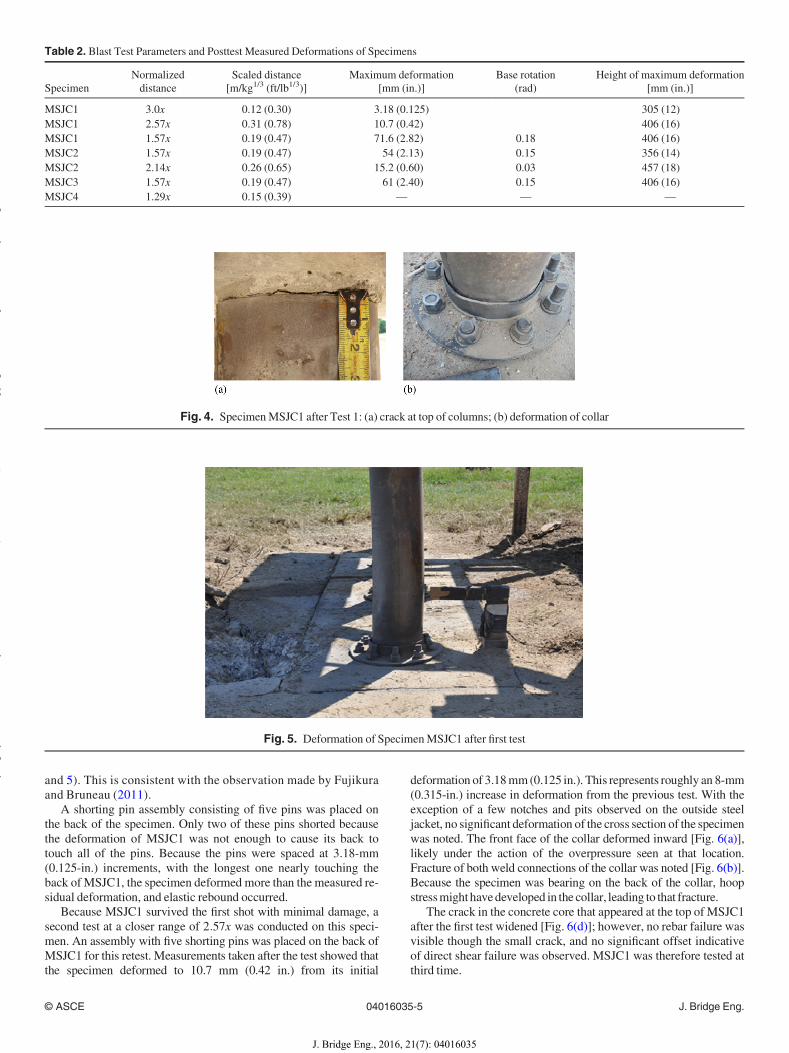
and 5). This is consistent with the observation made by Fujikuraand Bruneau (2011).A shorting pin assembly consisting of five pins was placed on
the back of the specimen. Only two of these pins shorted becausethe deformation of MSJC1 was not enough to cause its back totouch all of the pins. Because the pins were spaced at 3.18-mm(0.125-in.) increments, with the longest one nearly touching theback of MSJC1, the specimen deformed more than the measured re-sidual deformation, and elastic rebound occurred.Because MSJC1 survived the first shot with minimal damage, a
second test at a closer range of 2:57x was conducted on this speci-men. An assembly with five shorting pins was placed on the back ofMSJC1 for this retest. Measurements taken after the test showed thatthe specimen deformed to 10.7 mm (0.42 in.) from its initial
deformation of 3.18mm(0.125 in.). This represents roughly an 8-mm(0.315-in.) increase in deformation from the previous test. With theexception of a few notches and pits observed on the outside steeljacket, no significant deformation of the cross section of the specimenwas noted. The front face of the collar deformed inward [Fig. 6(a)],likely under the action of the overpressure seen at that location.Fracture of both weld connections of the collar was noted [Fig. 6(b)].Because the specimen was bearing on the back of the collar, hoopstressmighthavedeveloped in the collar, leading to that fracture.The crack in the concrete core that appeared at the top of MSJC1
after the first test widened [Fig. 6(d)]; however, no rebar failure wasvisible though the small crack, and no significant offset indicativeof direct shear failure was observed. MSJC1 was therefore tested atthird time.
Table 2. Blast Test Parameters and Posttest Measured Deformations of Specimens
SpecimenNormalizeddistance
Scaled distance[m/kg1/3 (ft/lb1/3)]
Maximum deformation[mm (in.)]
Base rotation(rad)
Height of maximum deformation[mm (in.)]
MSJC1 3.0x 0.12 (0.30) 3.18 (0.125) 305 (12)MSJC1 2.57x 0.31 (0.78) 10.7 (0.42) 406 (16)MSJC1 1.57x 0.19 (0.47) 71.6 (2.82) 0.18 406 (16)MSJC2 1.57x 0.19 (0.47) 54 (2.13) 0.15 356 (14)MSJC2 2.14x 0.26 (0.65) 15.2 (0.60) 0.03 457 (18)MSJC3 1.57x 0.19 (0.47) 61 (2.40) 0.15 406 (16)MSJC4 1.29x 0.15 (0.39) — — —
Fig. 4. SpecimenMSJC1 after Test 1: (a) crack at top of columns; (b) deformation of collar
Fig. 5. Deformation of SpecimenMSJC1 after first test
© ASCE 04016035-5 J. Bridge Eng.
J. Bridge Eng., 2016, 21(7): 04016035
yg
yy
()
pyg
py
g
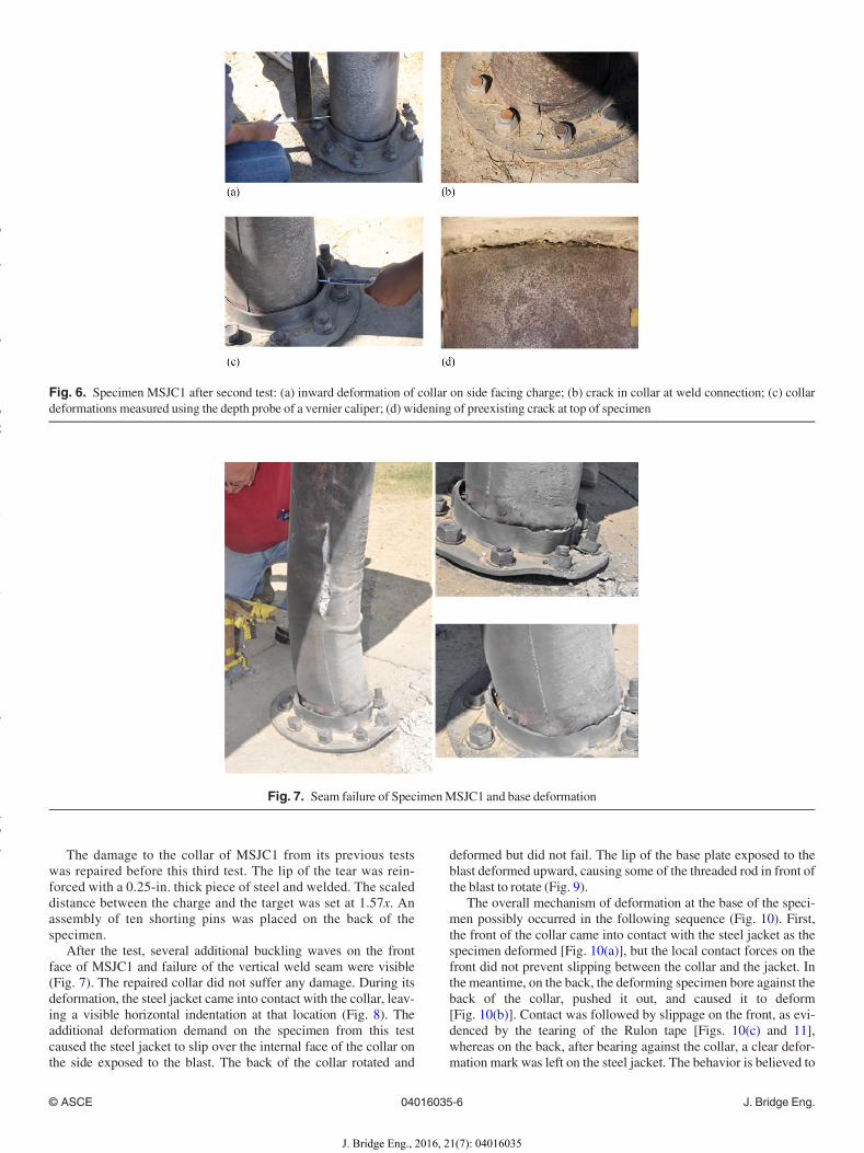
The damage to the collar of MSJC1 from its previous testswas repaired before this third test. The lip of the tear was rein-forced with a 0.25-in. thick piece of steel and welded. The scaleddistance between the charge and the target was set at 1:57x. Anassembly of ten shorting pins was placed on the back of thespecimen.After the test, several additional buckling waves on the front
face of MSJC1 and failure of the vertical weld seam were visible(Fig. 7). The repaired collar did not suffer any damage. During itsdeformation, the steel jacket came into contact with the collar, leav-ing a visible horizontal indentation at that location (Fig. 8). Theadditional deformation demand on the specimen from this testcaused the steel jacket to slip over the internal face of the collar onthe side exposed to the blast. The back of the collar rotated and
deformed but did not fail. The lip of the base plate exposed to theblast deformed upward, causing some of the threaded rod in front ofthe blast to rotate (Fig. 9).The overall mechanism of deformation at the base of the speci-
men possibly occurred in the following sequence (Fig. 10). First,the front of the collar came into contact with the steel jacket as thespecimen deformed [Fig. 10(a)], but the local contact forces on thefront did not prevent slipping between the collar and the jacket. Inthe meantime, on the back, the deforming specimen bore against theback of the collar, pushed it out, and caused it to deform[Fig. 10(b)]. Contact was followed by slippage on the front, as evi-denced by the tearing of the Rulon tape [Figs. 10(c) and 11],whereas on the back, after bearing against the collar, a clear defor-mation mark was left on the steel jacket. The behavior is believed to
Fig. 6. Specimen MSJC1 after second test: (a) inward deformation of collar on side facing charge; (b) crack in collar at weld connection; (c) collardeformations measured using the depth probe of a vernier caliper; (d) widening of preexisting crack at top of specimen
Fig. 7. Seam failure of SpecimenMSJC1 and base deformation
© ASCE 04016035-6 J. Bridge Eng.
J. Bridge Eng., 2016, 21(7): 04016035
yg
yy
()
pyg
py
g
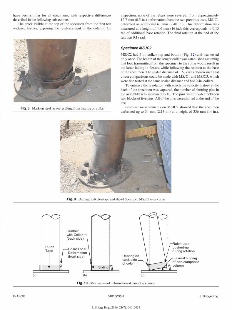
have been similar for all specimens, with respective differencesdescribed in the following subsections.The crack visible at the top of the specimen from the first test
widened further, exposing the reinforcement of the column. On
inspection, none of the rebars were severed. From approximately12.7-mm (0.5-in.) deformation from the two previous tests, MSJC1deformed an additional 61 mm (2.40 in.). This deformation wasmeasured at a height of 406 mm (16 in.); this corresponds to 0.15rad of additional base rotation. The final rotation at the end of thetest was 0.18 rad.
Specimen MSJC2
MSJC2 had 4-in. collars top and bottom (Fig. 12) and was testedonly once. The length of the longer collar was established assumingthat load transmitted from the specimen to the collar would result inthe latter failing in flexure while following the rotation at the baseof the specimen. The scaled distance of 1:57x was chosen such thatdirect comparisons could be made with MSJC1 and MSJC3, whichwere also tested at the same scaled distance and had 2-in. collars.To enhance the resolution with which the velocity history at the
back of the specimen was captured, the number of shorting pins inthe assembly was increased to 10. The pins were divided betweentwo blocks of five pins. All of the pins were shorted at the end of thetest.Postblast measurements on MSJC2 showed that the specimen
deformed up to 54 mm (2.13 in.) at a height of 356 mm (14 in.).Fig. 8. Mark on steel jacket resulting from bearing on collar
Fig. 9. Damage to Rulon tape and slip of SpecimenMSJC1 over collar
Collar LocalDeformation(front side)
Sliding
Contactwith Collar(back side)
RulonTape
Denting onback sideof column
Flexural hingingof non-compositecolumn
Rulon tapepushed-upduring rotation
(c)(a) (b)
Fig. 10. Mechanism of deformation at base of specimen
© ASCE 04016035-7 J. Bridge Eng.
J. Bridge Eng., 2016, 21(7): 04016035
yg
yy
()
pyg
py
g

This corresponds approximately to 0.15 rad of rotation at the baseof the specimen. Splitting and opening of the collar in the back ofthe specimen were observed as a consequence of this importantrotation demand (Fig. 13). Several buckling lobes (Fig. 14) devel-oped on the front face of the specimen. The jacketed column and thecollar came into contact near the top, as evidenced by a mark on thesteel jacket matching the location of the collar.
Specimen MSJC3
MSJC3 was identical to MSJC4 except that MSJC3 did not haveRulon tape at the interface between the steel jacket and the collar.MSJC3 was first tested at a scaled distance of 2:14x. The shortingpin assembly for this test consisted of five pins. Only four of the fivepins were deformed after the test.Deformation of the collar at the front and back of the specimen
was noted. A tear at the junction of the two halves of the collar atthe base was also observed, again possibly due to hoop stress in
the collar exceeding the capacity of the weld. The lip of the baseplate of this collar deformed upward, possibly due to blast over-pressure entering a small gap existing between the plate and thetop of the foundation. However, the top collar did not suffer anyvisible damage.MSJC3 did not deform much under load. The maximum perma-
nent deformation over the height of the specimen was 15.3 mm(0.60 in.) at a height of 457 mm (18 in., 0.03 rad). Measurement ofthe diameters of the specimen at the height of the blast chargeshowed that some marginal deformation in cross section occurred,but there was no significant ovalization of the section.After repairing the collar of MSJC3 to restore its resistance, the
specimen was retested. Some of the front nuts of the base plate werefound to be slightly loose after the prior tests because the lip of thebase plate had deformed upward. Therefore, the nuts were retight-ened prior to the second test. The shorting pin arrangement on theback of MSJC3 consisted of 10 pins mounted on two blocks. Thescaled distance was set at 1:57x.The final maximum deformation of MSJC3 was identical to that
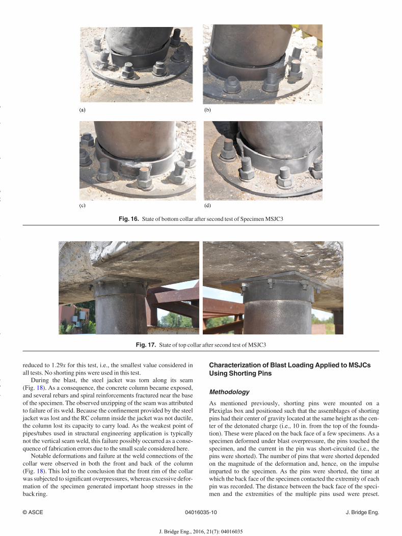
of MSJC1 [61 mm (2.40 in.) at a height of 406 mm (16 in.) or 0.18rad at the base]. The additional deformation from the first to the sec-ond test in that case was 45.7 mm (1.80 in.). Several buckling wavesdeveloped in the front face of MSJC3 (Fig. 15). Contrary to obser-vations on MSJC1, the seam of MSJC3 survived the test. For com-parison, note that MSJC3 was tested twice (at scaled distances of2:14x and 1:57x) and that MSJC1 was tested three times (at scaleddistances of 3:00x, 2:57x, and 1:57x).Plastic deformations (Fig. 16) in the bottom collar did not cause
failure at the weld connection, as observed in the first test. Slippagebetween the collar and the steel jacket was observed in mostly thesame fashion as in the last test onMSJC1 [Fig. 16(a)]. The top collarremained undamaged and virtually undeformed (Fig. 17).
Specimen MSJC4
MSJC4 was similar to MSJC1 except that, because direct shear fail-ure was anticipated at the top of the specimen and to prevent suchfailure, a collar was also provided at that location in addition to theone used at the bottom. The scaled distance for the specimen was
Fig. 11. Widening of crack at top of SpecimenMSJC1
Fig. 12. View of collars of SpecimenMSJC2
Fig. 13. Postshot failure of collar on SpecimenMSJC2
© ASCE 04016035-8 J. Bridge Eng.
J. Bridge Eng., 2016, 21(7): 04016035
yg
yy
()
pyg
py
g
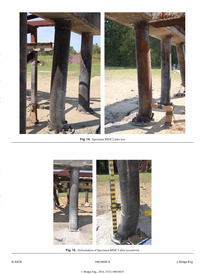
Fig. 14. SpecimenMSJC2 after test
Fig. 15. Deformation of SpecimenMSJC3 after second test
© ASCE 04016035-9 J. Bridge Eng.
J. Bridge Eng., 2016, 21(7): 04016035
yg
yy
()
pyg
py
g
reduced to 1:29x for this test, i.e., the smallest value considered inall tests. No shorting pins were used in this test.During the blast, the steel jacket was torn along its seam
(Fig. 18). As a consequence, the concrete column became exposed,and several rebars and spiral reinforcements fractured near the baseof the specimen. The observed unzipping of the seamwas attributedto failure of its weld. Because the confinement provided by the steeljacket was lost and the RC column inside the jacket was not ductile,the column lost its capacity to carry load. As the weakest point ofpipes/tubes used in structural engineering application is typicallynot the vertical seam weld, this failure possibly occurred as a conse-quence of fabrication errors due to the small scale considered here.Notable deformations and failure at the weld connections of the
collar were observed in both the front and back of the column(Fig. 18). This led to the conclusion that the front rim of the collarwas subjected to significant overpressures, whereas excessive defor-mation of the specimen generated important hoop stresses in theback ring.
Characterization of Blast Loading Applied toMSJCsUsing Shorting Pins
Methodology
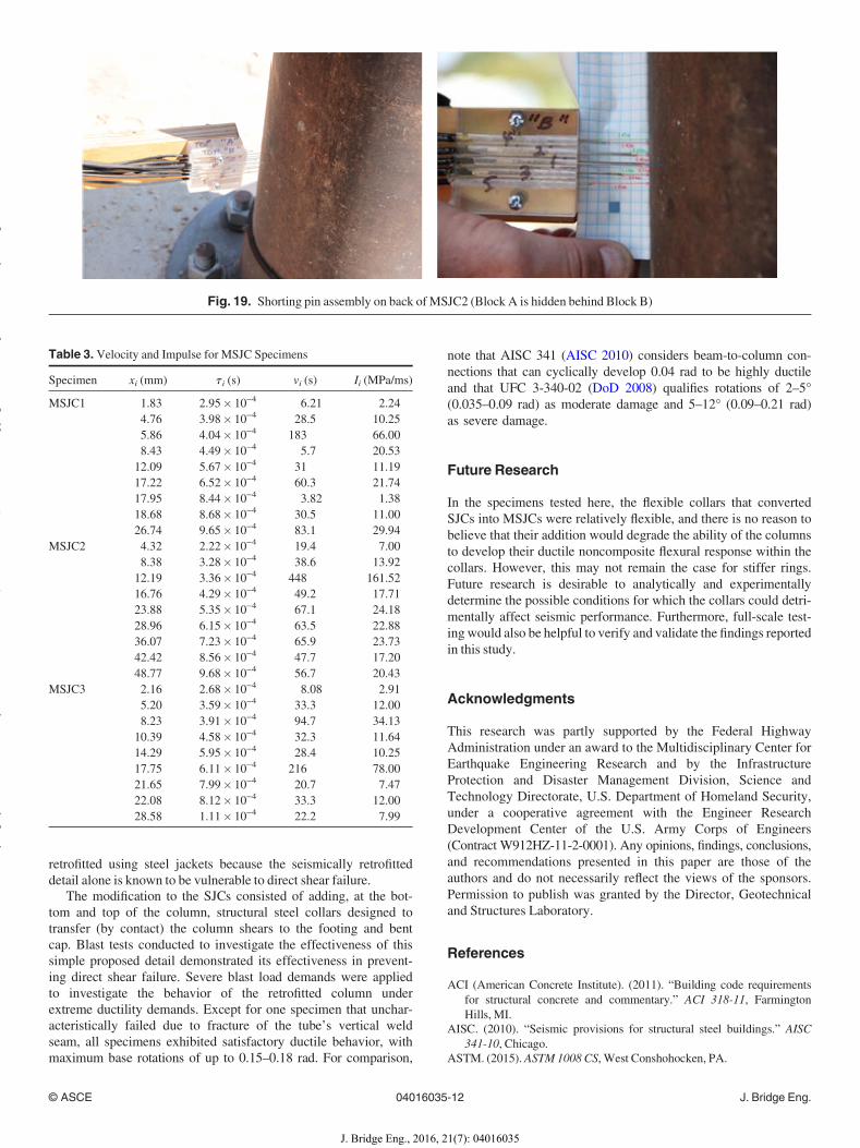
As mentioned previously, shorting pins were mounted on aPlexiglas box and positioned such that the assemblages of shortingpins had their center of gravity located at the same height as the cen-ter of the detonated charge (i.e., 10 in. from the top of the founda-tion). These were placed on the back face of a few specimens. As aspecimen deformed under blast overpressure, the pins touched thespecimen, and the current in the pin was short-circuited (i.e., thepins were shorted). The number of pins that were shorted dependedon the magnitude of the deformation and, hence, on the impulseimparted to the specimen. As the pins were shorted, the time atwhich the back face of the specimen contacted the extremity of eachpin was recorded. The distance between the back face of the speci-men and the extremities of the multiple pins used were preset.
Fig. 16. State of bottom collar after second test of SpecimenMSJC3
Fig. 17. State of top collar after second test of MSJC3
© ASCE 04016035-10 J. Bridge Eng.
J. Bridge Eng., 2016, 21(7): 04016035
yg
yy
()
pyg
py
g

Based on the spacings and times of arrival of the back face of thespecimen at the pin tips, a portion of the velocity history of the backface of the specimen could then be determined. An estimate of theresultant impulse at the height of burst could be established basedon the velocity history on the back face of a specimen. Thisapproach is valid provided that the cross section of the specimenmaintains its shape (as was the case here). For a deforming crosssection, each point of the cross section will be moving at a specificvelocity, and the estimate of the impulse will be somewhat affected.If the spacing between the extremities of Pins 1 to n and the back
face of the specimen at rest are designated by x1; x2; :::; xi; :::; xn,respectively, and the corresponding times at which contact with thepins occurs are t1; t2; :::; t i; :::; t n, then the velocities, vi , at whichthe back face of the specimen travels from the extremity of Pin i tothat of Pin iþ 1 can be obtained using
vi ¼ xiþ1 � xit iþ1 � t i
; 1 � i � n (13)
where n is the number of pins. The velocity history at the backface of the specimen is given by the pair ðt i; viÞ. If it is assumedthat the velocity history so calculated represents the velocity ofthe back of the specimen at the same height as the center of thecharge (which is where the pins are located), the resultantimpulse/unit length seen by that section can be estimated as theproduct of the mass of the section (mass/unit length of the speci-men) and the velocity so calculated. The impulse/unit area, ii,normally reported by software such as BEL 1.1.0.3 is obtainedby dividing the impulse/unit length, Ii, by the breadth or the di-ameter (D) of the section exposed to the blast
Ii ¼ mvi; 1 � i � n (14)
ii ¼ IiD; 1 � i � n (15)
Application to Test Series
It was found that, with less than 10 pins, the velocity history at theback of a specimen was too severely truncated, and no estimate ofthe peak or the deceleration of the specimen afterwards could beobtained for those cases. For specimens instrumented with 10 pins,Fig. 19 illustrates a typical pin assemblage on the back face of theelement. The 10 pins were split between two blocks (Blocks A andB) of five pins each, allowing the calculation of 10 data points ofthe velocity history on the back face of the specimen. The distan-ces between the tip of each pin and the back face of the specimenwere calculated, and the times of contact between the back face ofthe specimen and each pin were obtained from the data collectedfor the pins. The times of arrival for all specimens instrumentedwith the 10-pin assemblies are reported in Table 3, along with thevelocities and impulses calculated per the equations from the pre-vious section.
Summary and Conclusions
A MSJC concept has been proposed. This retrofit detail wasdesigned to add blast resistance to bridge columns seismically
Fig. 18. Global view and close-up of base of SpecimenMSJC4 after test
© ASCE 04016035-11 J. Bridge Eng.
J. Bridge Eng., 2016, 21(7): 04016035
yg
yy
()
pyg
py
g
retrofitted using steel jackets because the seismically retrofitteddetail alone is known to be vulnerable to direct shear failure.The modification to the SJCs consisted of adding, at the bot-
tom and top of the column, structural steel collars designed totransfer (by contact) the column shears to the footing and bentcap. Blast tests conducted to investigate the effectiveness of thissimple proposed detail demonstrated its effectiveness in prevent-ing direct shear failure. Severe blast load demands were appliedto investigate the behavior of the retrofitted column underextreme ductility demands. Except for one specimen that unchar-acteristically failed due to fracture of the tube’s vertical weldseam, all specimens exhibited satisfactory ductile behavior, withmaximum base rotations of up to 0.15–0.18 rad. For comparison,
note that AISC 341 (AISC 2010) considers beam-to-column con-nections that can cyclically develop 0.04 rad to be highly ductileand that UFC 3-340-02 (DoD 2008) qualifies rotations of 2–5°(0.035–0.09 rad) as moderate damage and 5–12° (0.09–0.21 rad)as severe damage.
Future Research
In the specimens tested here, the flexible collars that convertedSJCs into MSJCs were relatively flexible, and there is no reason tobelieve that their addition would degrade the ability of the columnsto develop their ductile noncomposite flexural response within thecollars. However, this may not remain the case for stiffer rings.Future research is desirable to analytically and experimentallydetermine the possible conditions for which the collars could detri-mentally affect seismic performance. Furthermore, full-scale test-ing would also be helpful to verify and validate the findings reportedin this study.
Acknowledgments
This research was partly supported by the Federal HighwayAdministration under an award to the Multidisciplinary Center forEarthquake Engineering Research and by the InfrastructureProtection and Disaster Management Division, Science andTechnology Directorate, U.S. Department of Homeland Security,under a cooperative agreement with the Engineer ResearchDevelopment Center of the U.S. Army Corps of Engineers(Contract W912HZ-11-2-0001). Any opinions, findings, conclusions,and recommendations presented in this paper are those of theauthors and do not necessarily reflect the views of the sponsors.Permission to publish was granted by the Director, Geotechnicaland Structures Laboratory.
References
ACI (American Concrete Institute). (2011). “Building code requirementsfor structural concrete and commentary.” ACI 318-11, FarmingtonHills, MI.
AISC. (2010). “Seismic provisions for structural steel buildings.” AISC341-10, Chicago.
ASTM. (2015). ASTM1008 CS, West Conshohocken, PA.
Table 3. Velocity and Impulse for MSJC Specimens
Specimen xi (mm) t i (s) vi (s) Ii (MPa/ms)
MSJC1 1.83 2.95� 10−4 6.21 2.244.76 3.98� 10−4 28.5 10.255.86 4.04� 10−4 183 66.008.43 4.49� 10−4 5.7 20.5312.09 5.67� 10−4 31 11.1917.22 6.52� 10−4 60.3 21.7417.95 8.44� 10−4 3.82 1.3818.68 8.68� 10−4 30.5 11.0026.74 9.65� 10−4 83.1 29.94
MSJC2 4.32 2.22� 10−4 19.4 7.008.38 3.28� 10−4 38.6 13.9212.19 3.36� 10−4 448 161.5216.76 4.29� 10−4 49.2 17.7123.88 5.35� 10−4 67.1 24.1828.96 6.15� 10−4 63.5 22.8836.07 7.23� 10−4 65.9 23.7342.42 8.56� 10−4 47.7 17.2048.77 9.68� 10−4 56.7 20.43
MSJC3 2.16 2.68� 10−4 8.08 2.915.20 3.59� 10−4 33.3 12.008.23 3.91� 10−4 94.7 34.1310.39 4.58� 10−4 32.3 11.6414.29 5.95� 10−4 28.4 10.2517.75 6.11� 10−4 216 78.0021.65 7.99� 10−4 20.7 7.4722.08 8.12� 10−4 33.3 12.0028.58 1.11� 10−4 22.2 7.99
Fig. 19. Shorting pin assembly on back ofMSJC2 (Block A is hidden behind Block B)
© ASCE 04016035-12 J. Bridge Eng.
J. Bridge Eng., 2016, 21(7): 04016035
yg
yy
()
pyg
py
g
BEL [Computer software]. U.S. Army Engineer Research and DevelopmentCenter, Vicksburg, MS.
Buckle, I. G., Friedland, I., Mander, J., Martin, G., Nutt, R., and Power, M.(2006). “Seismic retrofitting manual for highway structures: Part 1—Bridges.” Technical Rep. MCEER-06-SP10, Univ. at Buffalo, Buffalo,NY.
Caltrans. (1996). Earthquake retrofit guidelines for bridges, memo todesigners 20-4, Sacramento, CA.
Chai, Y. H. (1996). “An analysis of the seismic characteristics of steel-jacketed circular bridge columns”. Earthquake Eng. Struct. Dyn.,25(2), 149–161.
Chai, Y. H., Priestley, M. J. N., and Seible, F. (1991). “Seismic retrofit ofcircular bridge columns for enhanced flexural performance.” ACI Struct.J., 88(5), 572–584.
DoD (Department of Defense). (2008). “Structures to resist the effects of ac-cidental explosions.” Rep. UFC 3-340-02, Arlington, VA.
Fouch�e, P., and Bruneau, M. (2014). “Blast and seismic resistant concrete-filled double skin tubes and modified steel jacketed bridge columns.”Techinical Rep. MCEER-14-004, Univ. at Buffalo, Buffalo, NY.
Fujikura, S., and Bruneau, M. (2011). “Experimental investigation of seis-mically resistant bridge piers under blast loading.” J. Bridge Eng., 10.1061/(ASCE)BE.1943-5592.0000124, 63–71.
Fujikura, S., and Bruneau,M. (2012). “Dynamic analysis of multihazard-re-sistant bridge piers having concrete-filled steel tube under blast loading.”J. Bridge Eng., 10.1061/(ASCE)BE.1943-5592.0000270, 249–258.
Fujikura, S., Bruneau M., and Lopez-Garcia, D. (2008). “Experimentalinvestigation of multihazard resistant bridge piers having concrete-filledsteel tube under blast loading.” J. Bridge Eng., 10.1061/(ASCE)1084-0702(2008)13:6(586), 586–594.
Housner, G. W., and Thiel, C. C. (1990). “Competing against time: Reportof the Governor’s Board of Inquiry on the 1989 Loma PrietaEarthquake.” Earthquake Spectra, 6(4), 681–711.
Kim, S. H., and Shinozuka, M. (2004). “Development of fragility curves ofbridges retrofitted by column jacketing. Probab. Eng. Mech., 19(1),105–112.
Priestley, M. J. N., Seible, F., and Calvi, G. M. (1996). Seismic design andretrofit of bridges, JohnWiley& Sons, NewYork.
Priestley, M. J. N., Seible, F., Xiao, Y., and Verma, R. (1994). “Steel jacketretrofitting of reinforced concrete bridge columns for enhanced shearstrength—Part 1: Theoretical considerations and test design.” ACIStruct. J., 91(4), 394–405.
Shams, M., and Saadeghvaziri, M. A. (1997). “State of the art of concrete-filled steel tubular columns.” ACI Struct. J., 94(5), 558–571.
Williams, D., Holland, C., Williamson, E., Bayrak, O., Marchand, K., andRay, J. (2008). “Blast-resistant highway bridges: Design and detailingguidelines.” Proc., 10th Int. Conf. on Structures under Shock andImpact (SUSI), WIT Press, Southampton, U.K.
Woodson, S. C., and Baylot, J. T. (1999). “Structural collapse: Quarter-scale model experiments.” Technical Rep. SL-99-8, U.S. ArmyEngineer Research and Development Center, Vicksburg, MS.
© ASCE 04016035-13 J. Bridge Eng.
J. Bridge Eng., 2016, 21(7): 04016035
yg
yy
()
pyg
py
g