Embed Size (px)
Citation preview
Modification of BB1 pump vibration characteristics to meet ISO 13709 2nd edition (API 610 11th) limits
Simon Bradshaw, Global API Product Development ManagerSimon Bradshaw, Global API Product Development Manager
Eugene Sabini, Director of Research
ITT Goulds Pumps
Seneca Falls, NY
461
Summary of the pump in question #1Summary of the pump in question #1
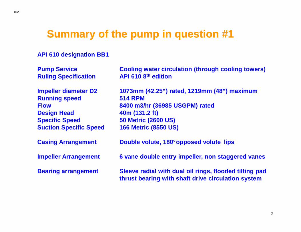
API 610 designation BB1
Pump Service Cooling water circulation (through cooling towers)Ruling Specification API 610 8 th edition
Impeller diameter D2 1073mm (42.25”) rated, 1219mm (48”) maximumRunning speed 514 RPMFlow 8400 m3/hr (36985 USGPM) rated Design Head 40m (131.2 ft)
2
Design Head 40m (131.2 ft)Specific Speed 50 Metric (2600 US)Suction Specific Speed 166 Metric (8550 US)
Casing Arrangement Double volute, 180°opposed volute lips
Impeller Arrangement 6 vane double entry impeller, non staggered vanes
Bearing arrangement Sleeve radial with dual oil rings, flooded tilting pad thrust bearing with shaft drive circulation system
462
Summary of the pump in question #2Summary of the pump in question #2
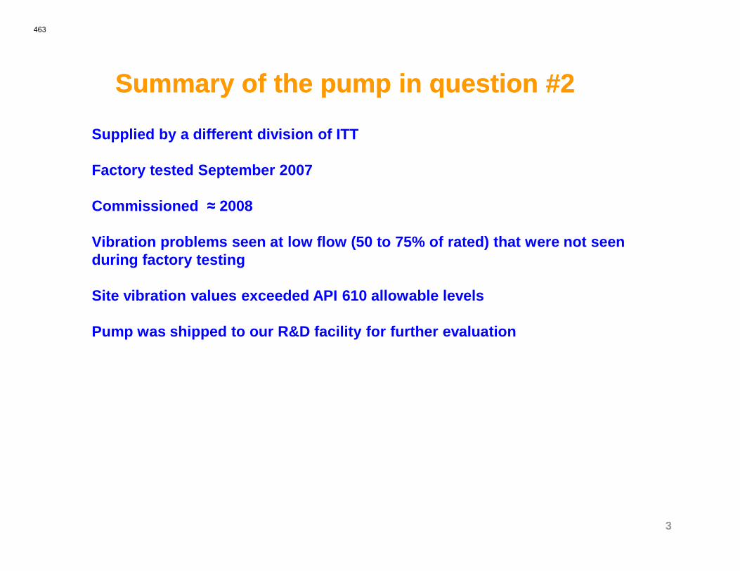
Supplied by a different division of ITT
Factory tested September 2007
Commissioned ≈ 2008
Vibration problems seen at low flow (50 to 75% of rated) that were not seen during factory testing
3
Site vibration values exceeded API 610 allowable lev els
Pump was shipped to our R&D facility for further evaluation
463
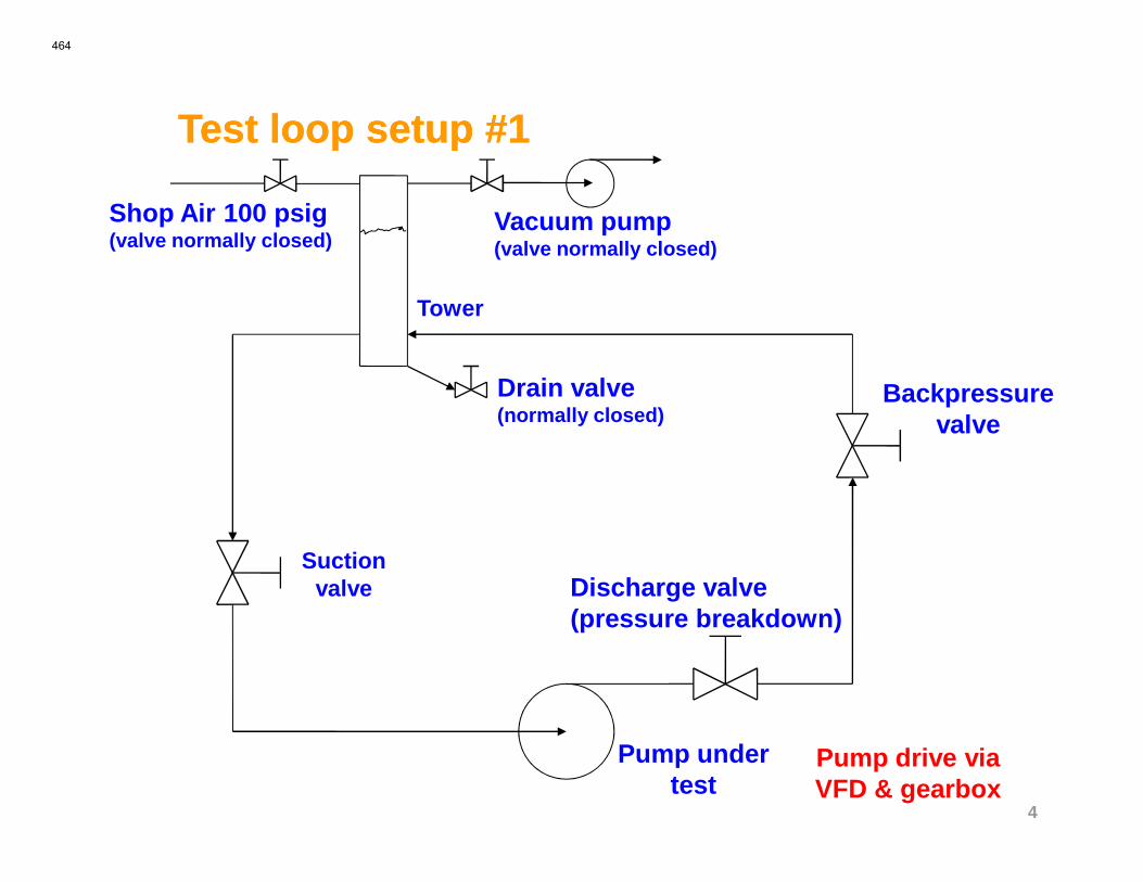
Test Test lloop setup #1oop setup #1
Backpressure valve
Drain valve(normally closed)
Shop Air 100 psig(valve normally closed)
Vacuum pump(valve normally closed)
Tower
4
Suction valve Discharge valve
(pressure breakdown)
Pump under test
Pump drive via VFD & gearbox
464
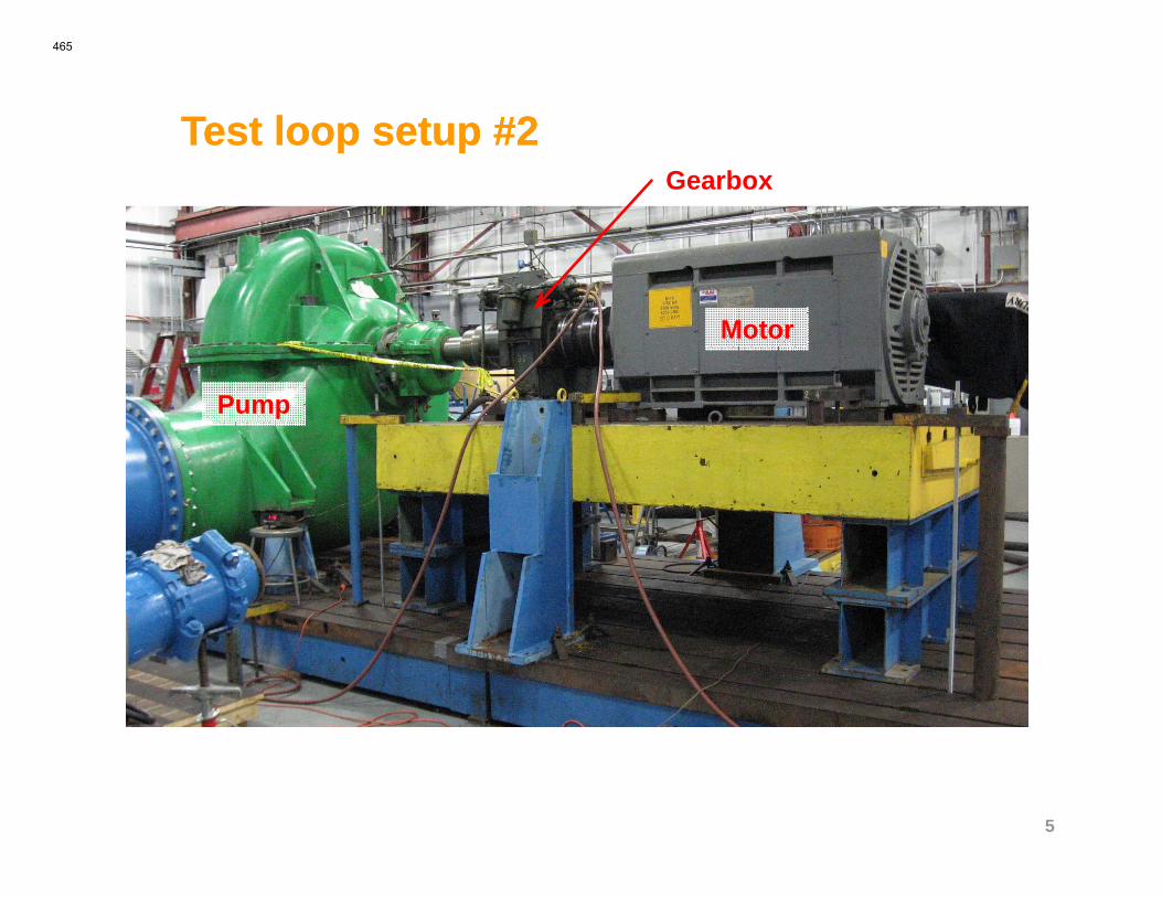
Test Test lloop setup #2oop setup #2Gearbox
Pump
Motor
5
465
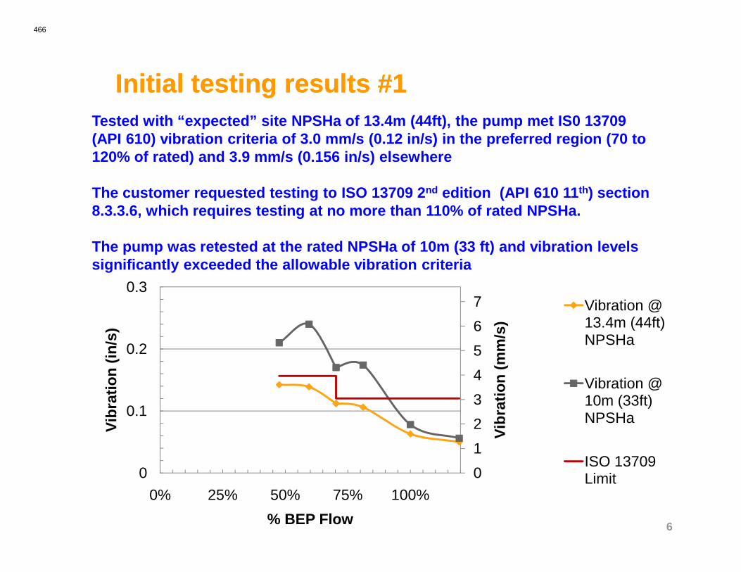
Initial testing results #1Initial testing results #1Tested with “expected” site NPSHa of 13.4m (44ft), th e pump met IS0 13709 (API 610) vibration criteria of 3.0 mm/s (0.12 in/s) in the preferred region (70 to 120% of rated) and 3.9 mm/s (0.156 in/s) elsewhere
The customer requested testing to ISO 13709 2 nd edition (API 610 11 th) section 8.3.3.6, which requires testing at no more than 110% of rated NPSHa.
The pump was retested at the rated NPSHa of 10m (33 ft) and vibration levels significantly exceeded the allowable vibration criteria
0.3
6
0
1
2
3
4
5
6
7
0
0.1
0.2
0.3
0% 25% 50% 75% 100%V
ibra
tion
(mm
/s)
Vib
ratio
n (in
/s)
% BEP Flow
Vibration @ 13.4m (44ft) NPSHa
Vibration @ 10m (33ft) NPSHa
ISO 13709 Limit
466
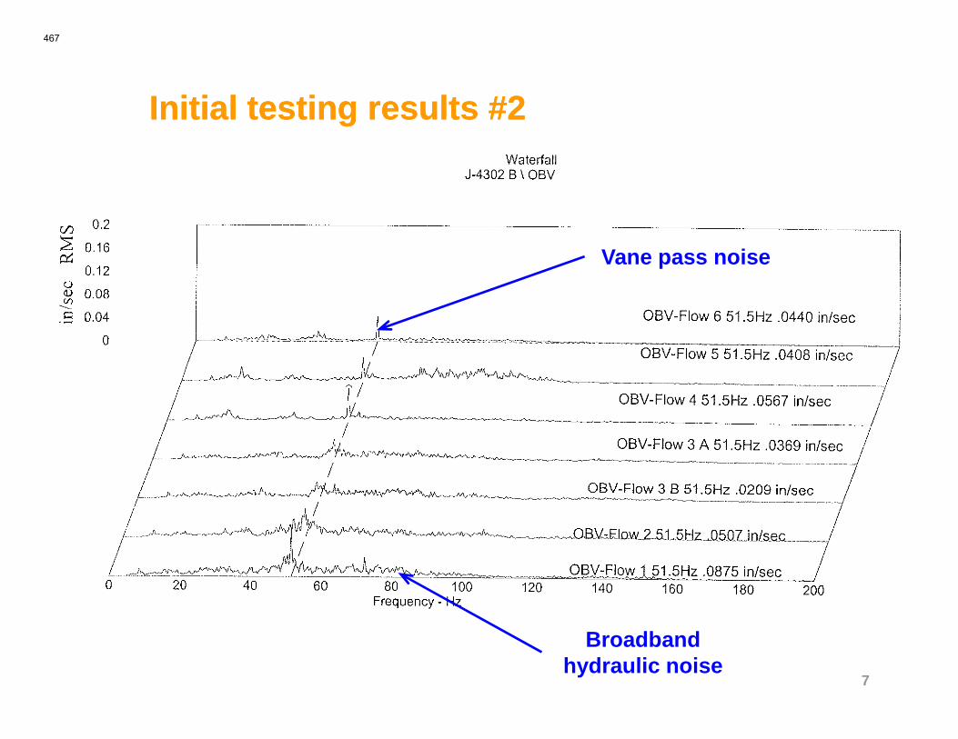
Initial testing results #2Initial testing results #2
Vane pass noise
7
Broadband hydraulic noise
467
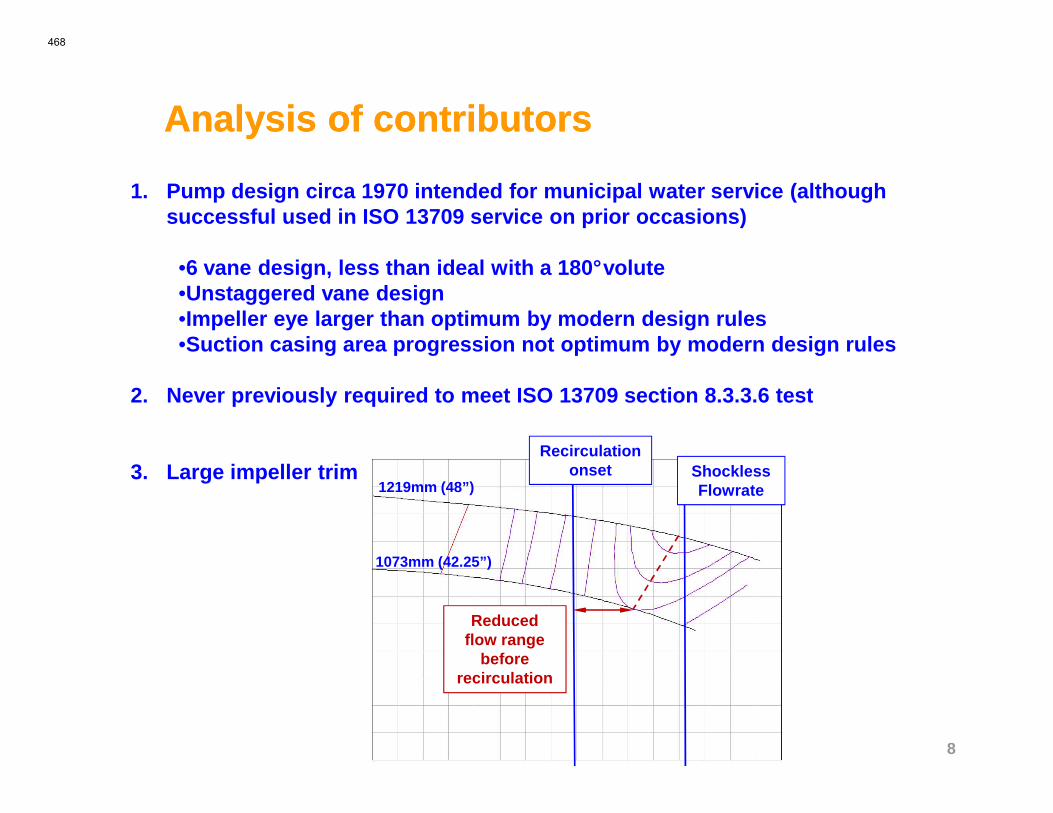
Analysis of contributorsAnalysis of contributors
1. Pump design circa 1970 intended for municipal wate r service (although successful used in ISO 13709 service on prior occasions)
•6 vane design, less than ideal with a 180°volute•Unstaggered vane design•Impeller eye larger than optimum by modern design rules•Suction casing area progression not optimum by modern design rules
2. Never previously required to meet ISO 13709 section 8.3.3.6 test
8
2. Never previously required to meet ISO 13709 section 8.3.3.6 test
3. Large impeller trim ShocklessFlowrate1219mm (48”)
1073mm (42.25”)
Recirculation onset
Reduced flow range
before recirculation
468
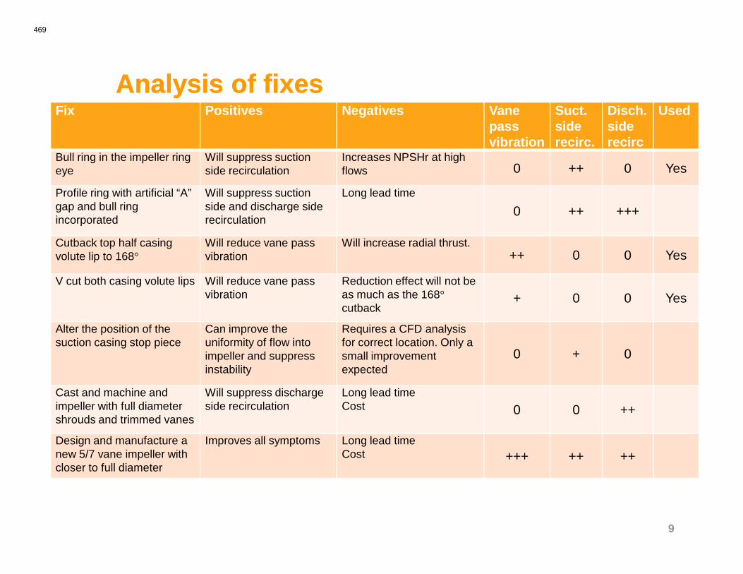
Analysis of fixesAnalysis of fixesFix Positives Negatives Vane
pass vibration
Suct. side recirc.
Disch. side recirc
Used
Bull ring in the impeller ring eye
Will suppress suction side recirculation
Increases NPSHr at high flows 0 ++ 0 Yes
Profile ring with artificial “A” gap and bull ring incorporated
Will suppress suction side and discharge side recirculation
Long lead time
0 ++ +++
Cutback top half casing volute lip to 168°
Will reduce vane pass vibration
Will increase radial thrust.++ 0 0 Yes
V cut both casing volute lips Will reduce vane pass Reduction effect will not be
9
vibration as much as the 168°cutback
+ 0 0 Yes
Alter the position of the suction casing stop piece
Can improve the uniformity of flow into impeller and suppress instability
Requires a CFD analysis for correct location. Only a small improvement expected
0 + 0
Cast and machine and impeller with full diameter shrouds and trimmed vanes
Will suppress discharge side recirculation
Long lead time Cost 0 0 ++
Design and manufacture a new 5/7 vane impeller with closer to full diameter
Improves all symptoms Long lead time Cost +++ ++ ++
469

Application of chosen Fixes #1Application of chosen Fixes #1A suction side restriction ring (commonly known as a “Bull Ring”), was added to the casing.
The purpose of this ring is to limit suction side impeller recirculation
Original inlet design
Revised inlet designRecirculation
10
Bull Ring
design designRecirculation
470
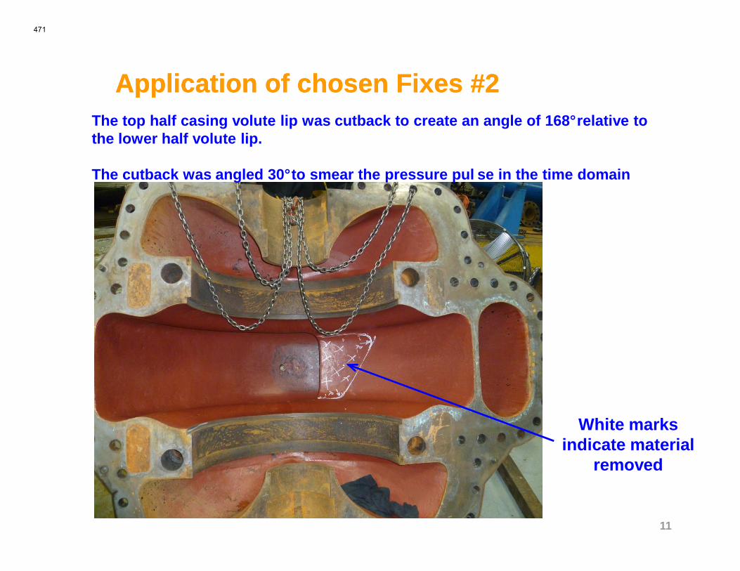
Application of chosen Fixes #2Application of chosen Fixes #2The top half casing volute lip was cutback to create an angle of 168°relative to the lower half volute lip.
The cutback was angled 30°to smear the pressure pul se in the time domain
11
White marks indicate material
removed
471
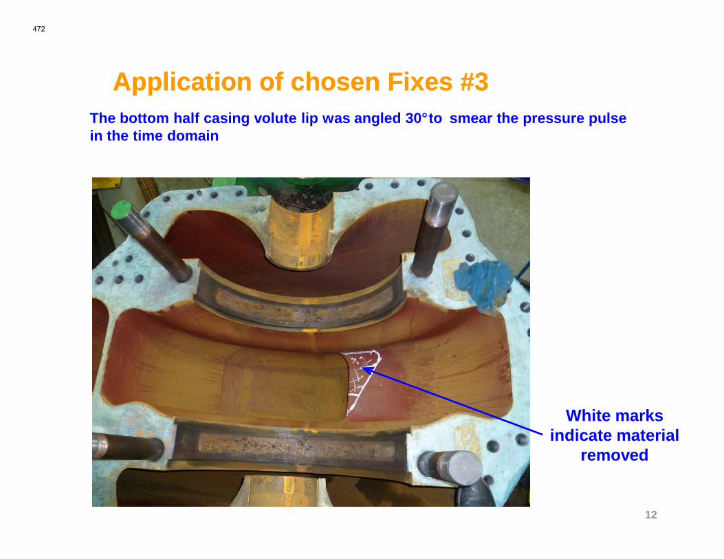
Application of chosen Fixes #3Application of chosen Fixes #3The bottom half casing volute lip was angled 30°to smear the pressure pulse in the time domain
12
White marks indicate material
removed
472

Testing results after modifications #1Testing results after modifications #1Testing confirmed the effectiveness of the modificat ions at suppressing low flow vibration behavior, but created a problem at higher flows.
So what went wrong ?
6
70.3
Vib
ratio
n (m
m/s
)
Vibration before mods @ 10m (33ft)
13
0
1
2
3
4
5
0
0.1
0.2
0% 25% 50% 75% 100%V
ibra
tion
(mm
/s)
Vib
ratio
n (in
/s)
% BEP Flow
@ 10m (33ft) NPSHa
Vibration after mods @ 10m (33ft) NPSHa
ISO 13709 Limit
473
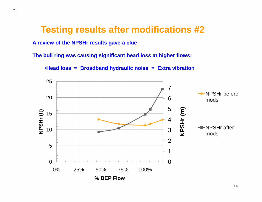
Testing results after modifications #2Testing results after modifications #2A review of the NPSHr results gave a clue
The bull ring was causing significant head loss at higher flows:
•Head loss = Broadband hydraulic noise = Extra vibration
6
7
20
25
NPSHr before mods
14
0
1
2
3
4
5
6
0
5
10
15
0% 25% 50% 75% 100%
NP
SH
r(m
)
NP
SH
r(f
t)
% BEP Flow
mods
NPSHr after mods
474
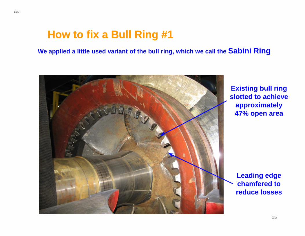
How to fix a Bull Ring #1How to fix a Bull Ring #1We applied a little used variant of the bull ring, w hich we call the Sabini Ring
Existing bull ring slotted to achieve
approximately 47% open area
15
Leading edge chamfered to reduce losses
475
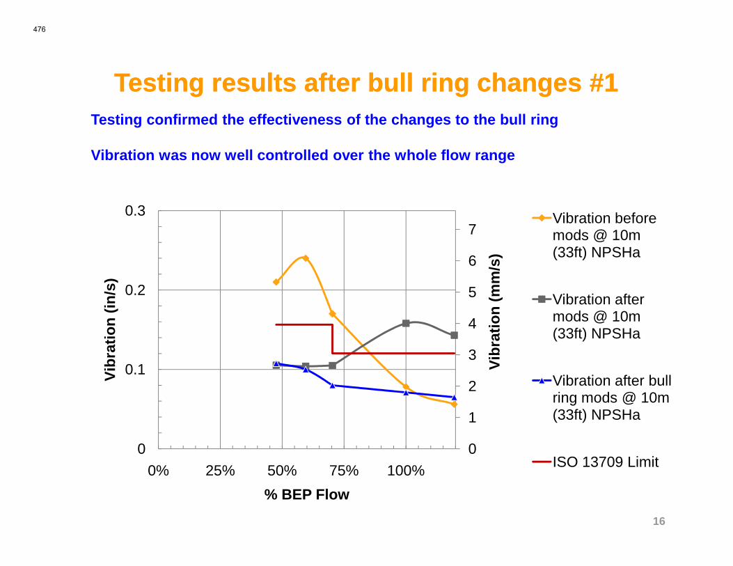
Testing results after bull ring changes #1Testing results after bull ring changes #1Testing confirmed the effectiveness of the changes t o the bull ring
Vibration was now well controlled over the whole flow range
6
7
0.2
0.3
Vib
ratio
n (m
m/s
)
Vib
ratio
n (in
/s)
Vibration before mods @ 10m (33ft) NPSHa
16
0
1
2
3
4
5
0
0.1
0.2
0% 25% 50% 75% 100%
Vib
ratio
n (m
m/s
)
Vib
ratio
n (in
/s)
% BEP Flow
Vibration after mods @ 10m (33ft) NPSHa
Vibration after bull ring mods @ 10m (33ft) NPSHa
ISO 13709 Limit
476
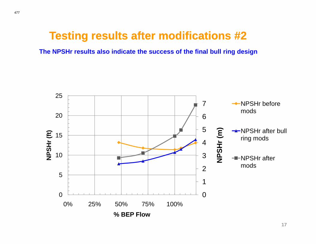
Testing results after modifications #2Testing results after modifications #2The NPSHr results also indicate the success of the fi nal bull ring design
6
7
20
25NPSHr before mods
17
0
1
2
3
4
5
0
5
10
15
0% 25% 50% 75% 100%
NP
SH
r(m
)
NP
SH
r(f
t)
% BEP Flow
NPSHr after bull ring mods
NPSHr after mods
477
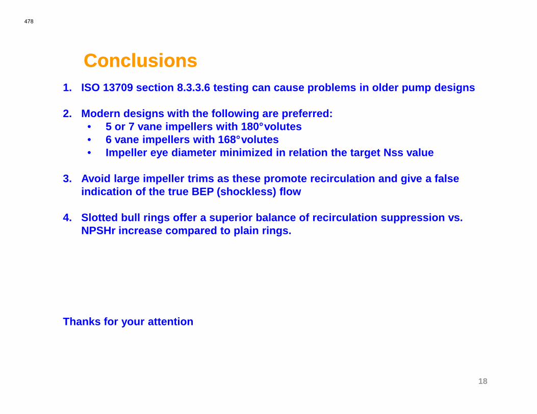
ConclusionsConclusions1. ISO 13709 section 8.3.3.6 testing can cause proble ms in older pump designs
2. Modern designs with the following are preferred:• 5 or 7 vane impellers with 180°volutes• 6 vane impellers with 168°volutes• Impeller eye diameter minimized in relation the target Nss value
3. Avoid large impeller trims as these promote recirculation and give a false indication of the true BEP (shockless) flow
18
4. Slotted bull rings offer a superior balance of rec irculation suppression vs. NPSHr increase compared to plain rings.
Thanks for your attention
478