Embed Size (px)
Citation preview
56034903 © 2008 Telular Corporation
TELGUARD® DIGITAL.
TG-7
GSM Digital Cellular Alarm Transmission System
MODEL (TG-7) MODEL (TG-7A) MODEL (TG-KIT)
INSTALLATION AND OPERATING INSTRUCTIONS COMPANY CONFIDENTIAL
For use by TELGUARD® customers only. Distribution to others strictly prohibited.
Technical Support: 800-229-2326 M-F 8AM – 8PM EST
Saturday 9AM – 5PM EST
August 1, 2008
TELGUARD® is a registered trademark of Telular Corporation. Products are protected under one or more of the following U.S. patents: 4,658,096 4,737,975 4,775,997 4,868,519 4,922,517 © 2006 Telular Corporation
C O R P O R A T I O N
®
T E L U L A R
56034903 © 2008 Telular Corporation I
FOREWORD A word about the significance of our UL Listings: These UL Listings allow the Telguard® models to meet certain requirements of insurance companies, fire marshals, building inspectors and other regulatory authorities in burglary and fire alarm service as follows: 1. In Burglary Alarm Service: When used in conjunction with a UL listed central station burglary alarm
control unit with integral or Listed DACT, the combined control communicator (C/C) and Telguard TG-7A is suitable for central station service.
A UL Listing is available in installations where the host Listed burglary alarm control/communicator transmits through the TG-7A solely on cellular (“Cellular only”: No Telco; Cellular primary). Also, where the control communicator is switched to transmit over cellular when it cannot reach the central station over Telco (“Cellular backup for Telco”: Telco primary; Cellular secondary). The specific UL Listing for the TG-7A with respect to burglary alarm service is Residential Burglary, UL1023. Central Station Burglar Alarm Systems, UL1610; Police Station Connected Alarm Systems, UL365; and Digital Alarm Communicators, UL1635.
2. In Fire Alarm Service (Residential): When used in conjunction with a Listed central station fire alarm control unit with a Listed DACT, the combined control communicator and Telguard meet the requirements for residential fire alarm usage under UL985.
Appendices A3.1 through A3.3.1 (burglary alarm service) and A3.4 through A3.5.1 (fire alarm service) show the installation configurations and the connections that must be made to meet various UL Listing requirements.
56034903 © 2008 Telular Corporation II
NOTICES
ABOUT THIS MANUAL This manual assumes that you have basic security system installation skills such as measuring voltages, stripping wire, properly connecting wires together, connecting wires to terminals, and checking phone lines. It also assumes that you have a familiarity with the proper installation and programming tasks related to various control communicator panels. The material and instructions covered in this manual have been carefully checked for accuracy and are presumed to be reliable. However, Telular assumes no responsibility for inaccuracies and reserves the right to modify and revise this manual without notice. It is our goal at Telular to always supply accurate and reliable documentation. If a discrepancy is found in this documentation, please mail or fax a photocopy of the corrected material to:
Telular Security Products Technical Services Department 2727 Paces Ferry Road SE Suite 1-800 Atlanta, GA USA 30339 Fax: 678-945-1651
© 2008 Telular Corporation. Atlanta, GA U.S.A. All rights reserved.
FCC Notices
EXPOSURE TO RADIO FREQUENCY ENERGY In 1991, the Institute of Electrical and Electronics Engineers (IEEE), and in 1992, the American National Standards Institute (ANSI), updated the 1982 ANSI Standard for safety levels with respect to human exposure to RF energy. Over 120 scientists, engineers and physicians from universities, government health agencies and industry, after reviewing the available body of research, developed this updated Standard. In March 1993, the U.S. Federal Communications Commission (FCC) proposed the adoption of this updated Standard. The design of your Telular Telguard complies with this updated Standard. Of course, if you want to limit RF exposure even further than the updated ANSI Standard, you may choose to install the unit in a manner that locates its antenna at an even greater distance from the general public than is recommended as a minimum by the standard. To insure compliance with the standard, when selecting a mounting location for your Telguard do not mount it (or its associated antenna) in an area where the general public could reasonably be within 8 inches (20 centimeters) of the antenna. NOTICE: This device complies with Part 15 of the FCC Rules. Operation is subject to the following two conditions:
(1) this device may not cause harmful interference, and (2) this device must accept any interference received, including interference that may cause
undesired operation. NOTICE: Changes or modifications made to this equipment not expressly approved by (manufacturer name) may void the FCC authorization to operate this equipment.
56034903 © 2008 Telular Corporation III
EFFICIENT OPERATION Do not operate your Telular product when holding the antenna. Be sure to mount the unit such that its antenna is a minimum of eight (8) inches (20 centimeters) is maintained from the general public.
For the best service quality,
• Keep the antenna free from obstructions and point the antenna straight up.
56034903 © 2008 Telular Corporation IV
ANTENNA CARE AND REPLACEMENT Do not use the unit with a damaged antenna. If a damaged antenna comes into contact with the skin, a minor burn may result. Have your antenna replaced by a qualified technician immediately. Use only a manufacturer-approved antenna. Non-approved antennas, modifications, or attachments could impair service quality, damage the Telguard and violate FCC regulations.
ELECTRONIC DEVICES Most modern electronic equipment is shielded from RF energy. However, RF energy from cellular devices may affect inadequately shielded electronic equipment. RF energy may affect improperly installed or inadequately shielded electronic equipment operating in homes and businesses. Check with the manufacturer or its representative to determine if these systems are adequately shielded from external RF energy. Consult the manufacturer of any personal medical devices (such as pacemakers, hearing aids, etc.) to determine if they are adequately shielded from external RF energy. NOTE: This equipment has been tested and found to comply with the limits for a Class B digital device, pursuant to Part 15 of the FCC Rules. These limits are designed to provide reasonable protection against harmful interference in a residential installation. This equipment generates, uses and can radiate radio frequency energy and, if not installed and used in accordance with the instructions, may cause harmful interference to radio communications. However, there is no guarantee that interference will not occur in a particular installation. If this equipment does cause harmful interference to radio or television reception, which can be determined by turning the equipment off and on, the user is encouraged to try to correct the interference by one or more of the following measures:
• Reorient or relocate the receiving antenna. • Increase the separation between the equipment and receiver. • Connect the equipment into an outlet on a circuit different from that to which the receiver is connected. • Consult the dealer or an experienced radio/TV technician for help.
BLASTING AREAS To avoid interfering with blasting operations, turn OFF your unit when in a “blasting area” or in areas posted: “Turn off two-way radio.” Construction crews often use remote control RF devices to set off explosives.
POTENTIALLY EXPLOSIVE ATMOSPHERES Turn OFF your unit when in any area with a potentially explosive atmosphere. It is rare, but your Telguard Digital or its accessories could generate sparks. Sparks in such areas could cause an explosion or fire resulting in bodily injury or even death. Areas with a potentially explosive atmosphere are often, but not always, clearly marked. They include fueling areas such as gas stations; below deck on boats; fuel or chemical transfer or storage facilities; areas where the air contains chemicals or particles, such as grain, dust, or metal powders; and any other area where you would normally be advised to turn off your vehicle engine. Do not transport or store flammable gas, liquid or explosives in the area of your Telguard Digital or accessories. Vehicles using liquefied petroleum gas (such as propane or butane) must comply with the National Fire Protection Standard (FPA-58). For a copy of this standard, contact the National Fire Protection Association, One Batterymarch Park, Quincy, MA 02269, Attn: Publications Sales Division.
56034903 © 2008 Telular Corporation V
PART 68 This equipment complies with Part 68 of the FCC Rules. Located on the inside of the hinged door of Telguard® models TG-7 and TG-7A is a label that contains, among other information, the FCC Registration Number and Ringer Equivalence Number (REN) for this equipment. If requested, this information must be provided to the Telephone Company. The Telguard - Cellular Alarm Transmission System is registered for connection to the public telephone network using an RJ38X or RJ31X jack. When selecting a mounting location, do not mount this unit in an area where the general public could reasonably be within 20cm (8 inches) of the antenna. The ringer equivalence number (REN) is used to determine the quantity of devices which may be connected to the telephone line. Excessive REN's on the telephone line may result in the devices not ringing in response to an incoming call. In most, but not all areas, the sum of the REN's should not exceed five (5.0). To be certain of the number of devices that may be connected to the line, as determined by the total number of REN's, contact the telephone company to determine the maximum of REN for the calling area. If the Telguard® Cellular Alarm Transmission System caused harm to the telephone network, the Telephone Company will notify you in advance that temporary discontinuance of the service may be required. But if advance notice is not practical, the Telephone Company will notify the customer as soon as possible. Also, you will be advised of your rights to file a complaint with the FCC if you believe it is necessary. The telephone company may make changes in it's facilities, equipment, operation, or procedures that could affect the operation of the equipment. If this happens, the Telephone Company will provide advance notice in order for you to make the necessary modifications in order to maintain uninterrupted service. If trouble is experienced with the Telguard® Cellular Alarm Transmission System please contact Telular Technical Service in the U.S.A. for repair and (or) warranty information.
Telular Corporation Technical Support
Phone: (800) 229-2326 option 9 If the trouble is causing harm to the telephone network, the Telephone Company may request that you remove the equipment from the network until the problem is resolved. The customer (user) should not attempt any repair to the Telguard® Cellular Alarm Transmission System. Repair of this equipment should be referred to only qualified technical personnel. Note that this equipment cannot be used on the public coin service provided by the Telephone Company. Connection to Party Line Service is subject to state tariffs. (Contact the state public utility commission or corporation commission for information).
56034903 © 2008 Telular Corporation VI
FUTURE TESTING AND LIMITATIONS ON USE Telguard® is part of an advanced design alarm-communication system. It does not offer guaranteed protection against burglary and fire. Any alarm communication system is subject to compromise or failure. The Telguard® will not work without power. Devices powered by AC will not work if the AC power supply is off for any reason, however briefly, and at the same time, the backup battery is missing, dead or not properly installed. The cellular radio network, needed to transmit alarm signals from a protected premises to a central monitoring station, may be inoperable or temporarily out of service. Cellular radio networks are also subject to compromise by sophisticated methods of attack. This equipment, like any other electrical device is subject to component failure. Although this equipment is designed to be long lasting, the electrical components could fail at any time. Due to these limitations, we recommend that if the automatic self-test feature is not enabled, other arrangements be made with the user to test the system at least once every three months. Moreover, arrangements should also be made for on site inspection/test by a licensed alarm installer at least once each year.
TERMS AND CONDITIONS FOR USE OF TELGUARD® PRODUCTS (“PRODUCT”) These Terms and Conditions are a legal contract between you and Telular Corporation for the title to and use of the Product. BY RETAINING AND USING THE PRODUCT YOU AGREE TO THE TERMS AND CONDITIONS INCLUDING WARRANTY DISCLAIMERS, LIMITATIONS OF LIABILITY AND INDEMNIFICATION PROVISIONS BELOW. IF YOU DO NOT AGREE TO THE TERMS AND CONDITIONS, DO NOT USE THE PRODUCT AND IMMEDIATELY RETURN THE UNUSED PRODUCT FOR A COMPLETE REFUND. You agree to accept sole responsibility for any misuse of the Product by you; and, in addition, any negligent or illegal act or omission of your or your agents, contractors, servants, employees, or other users of the Product so long as the Product was obtained from you, in the use and operation of the Product.
INDEMNIFICATION OF TELULAR CORPORATION (“TELULAR”) YOU SHALL INDEMNIFY, DEFEND AND HOLD HARMLESS TELULAR FOR ANY OF THE COST, INCLUDING REASONABLE ATTORNEYS’ FEES, AND FROM CLAIMS ARISING OUT OF YOU, YOUR CLIENTS’ OR OTHER THIRD PARTIES’ USE OR OPERATION OF THE PRODUCT: (i) FOR MISUSE OR IN A MANNER NOT CONTEMPLATED BY YOU AND TELULAR OR INCONSISTENT WITH THE PROVISIONS OF THIS MANUAL; (ii) IN AN ILLEGAL MANNER OR AGAINST PUBLIC POLICY; (iii) IN A MANNER SPECIFICALLY UNAUTHORIZED IN THIS MANUAL; (iv) IN A MANNER HARMFUL OR DANGEROUS TO THIRD PARTIES; (v) FROM CLAIMS BY ANYONE RESPECTING PROBLEMS, ERRORS OR MISTAKES OF THE PRODUCT; OR (vi) COMBINATION OF THE PRODUCT WITH MATERIAL, MODIFICATION OF THE PRODUCT OR USE OF THE PRODUCT IN AN ENVIRONMENT NOT PROVIDED, OR PERMITTED, BY TELULAR IN WRITING. THE PARTIES SHALL GIVE EACH OTHER PROMPT NOTICE OF ANY SUCH COST OR CLAIMS AND COOPERATE, EACH WITH THE OTHER, TO EFFECTUATE THIS INDEMNIFICATION, DEFENSE AND HOLD HARMLESS.
WARRANTY; LIMITATIONS Telular will repair or replace (our option) inoperative units for up to two years from date of manufacture. This excludes damage due to lightning or installer error. Unauthorized modifications void this warranty. Not responsible for incidental or consequential damages. Liability limited to price of unit. This is the exclusive warranty and no other warranties will be honored, whether expressed or implied. An RMA must be assigned by calling tech support 800-229-2326 before returning product to: RMA must be visible on outside of package.
Telular Corporation Attn: Repair Depot
1801 South Fulton Drive Corinth, MS 38834
56034903 © 2008 Telular Corporation VII
TABLE OF CONTENTS
FOREWORD .................................................................................................................................................. I
NOTICES ....................................................................................................................................................... II ABOUT THIS MANUAL .................................................................................................................................... II
FCC NOTICES .............................................................................................................................................. II EXPOSURE TO RADIO FREQUENCY ENERGY .................................................................................................. II EFFICIENT OPERATION ................................................................................................................................ III ANTENNA CARE AND REPLACEMENT ........................................................................................................... IV ELECTRONIC DEVICES ......................................................................................................................... IV BLASTING AREAS .................................................................................................................................. IV POTENTIALLY EXPLOSIVE ATMOSPHERES ....................................................................................... IV
PART 68 ....................................................................................................................................................... V
FUTURE TESTING AND LIMITATIONS ON USE ...................................................................................... VI TERMS AND CONDITIONS FOR USE OF TELGUARD® PRODUCTS (“PRODUCT”) .............................. VI INDEMNIFICATION OF TELULAR CORPORATION (“TELULAR”) ........................................................ VI WARRANTY; LIMITATIONS .................................................................................................................... VI
1.0 GENERAL DESCRIPTION AND OPERATION .............................................................................. 1
2.0 FEATURES ..................................................................................................................................... 1 2.1 OPERATING MODE ......................................................................................................................... 1
2.1.1 Auto Format Detection ............................................................................................................. 1 2.2 C/C COMMUNICATION FORMATS ..................................................................................................... 2 2.3 COMPLETE SUPERVISION OF COMMUNICATION PATHS ..................................................................... 2
2.3.1 Line Fault Condition (LFC) ....................................................................................................... 2 2.3.2 No Service Condition (NSC) .................................................................................................... 2 2.3.3 Radio Communications Failure Condition (RFC) ..................................................................... 2
2.4 COMPLETE POWER SUPERVISION ................................................................................................... 2 2.4.1 Low/Missing Battery Condition (LBC) ...................................................................................... 2 2.4.2 AC Failure Condition (ACFC) ................................................................................................... 3 2.4.3 Dial Tone Failure (DTF) ........................................................................................................... 3 2.4.4 Catastrophic Failure (CF) ......................................................................................................... 3
2.5 TELGUARD AUTOMATIC SELF-TEST REPORT .................................................................................... 3 2.5.1 Telguard Remote Query Capability .......................................................................................... 3
2.6 TELGUARD TERMINAL STRIP CONNECTIONS .................................................................................... 3 2.6.1 Programmable Supervisory Trip Outputs (STC1 and STC2) Relays ....................................... 3
2.7 DIAGNOSTIC AND STATUS LEDS ..................................................................................................... 4 2.7.1 LED Signal Strength Indication ................................................................................................ 5
2.8 TELGUARD SETUP PROGRAMMING PARAMETERS ............................................................. 5 2.9 UL LISTINGS BY MODEL ........................................................................................................... 5
2.9.1 Model TG-7 .............................................................................................................................. 5 2.9.2 Model TG-7A ............................................................................................................................ 5
3.0 GETTING READY .......................................................................................................................... 6 3.1 DEALER ACCOUNT ESTABLISHMENT ................................................................................................ 6 3.2 SUBSCRIBER ACCOUNT REGISTRATION FOR ACTIVATION ................................................................. 6 3.3 PRE-INSTALLATION CHECKLIST ....................................................................................................... 6
4.0 INSTALLATION SUMMARY ........................................................................................................... 7 4.1 REGISTER & ACTIVATE THE TELGUARD ON CELLULAR NETWORK ....................................................... 7 4.2 TRANSMIT C/C ALARMS OVER THE TELCO CONNECTION .................................................................. 7 4.3 TRANSMIT C/C ALARMS OVER THE CELLULAR RADIO NETWORK ....................................................... 7
56034903 © 2008 Telular Corporation VIII
4.4 CONNECT SUPERVISORY TRIP OUTPUTS ......................................................................................... 7 4.5 COMPLETE THE INSTALLATION ........................................................................................................ 7
5.0 INSTALLATION STEPS ................................................................................................................. 7 5.1 STEP 1: ACTIVATE & REGISTER THE TELGUARD UNIT ...................................................................... 7
5.1.1 Activate Cellular Service .......................................................................................................... 7 5.1.2 Locate Unit ............................................................................................................................... 7 5.1.3 Connect Backup Battery and AC Power Transformer ............................................................. 8 5.1.4 Connect Antenna and Temporarily Place Unit ......................................................................... 8
5.1.4.1 Tips for Improved Radio Signal Reception ......................................................................................... 8 5.1.5 Measure Received Signal Strength for Best Antenna Placement ........................................... 8
5.1.5.1 Antenna Options ................................................................................................................................ 9 5.2 STEP 2: TRANSMIT C/C ALARMS OVER THE TELCO CONNECTION ..................................................... 9
5.2.1 Connect C/C to Telguard Jack 7 (BLACK Connector) ............................................................. 9 5.2.2 Connect Telguard to RJ-31x Jack 6 (GRAY Connector) ......................................................... 9 5.2.3 Verify Alarm Signal Transmissions over Telco ........................................................................ 9
5.3 STEP 3: PROGRAM THE TELGUARD FOR ALARM TRANSMISSION ........................................................ 9 5.3.1 Setup & Programming the Operating Parameters in the Telguard ........................................ 10
5.3.1.1 Command Key Sequences for Pots Programming........................................................................... 10 5.3.2 Complete the Telguard Programming Data Sheet ................................................................. 11 5.3.3 Disconnect Telguard from RJ-31x Jack ................................................................................. 12 5.3.4 Verify Alarm Signal Transmissions over Cellular ................................................................... 12
5.4 STEP 4: CONNECT SUPERVISORY TRIP OUTPUTS .......................................................................... 12 5.4.1 Decide on a STC Trip Output Strategy .................................................................................. 12 5.4.2 Check Telguard Supervisory Trip to C/C ............................................................................... 12
5.4.2.1 Reprogram C/C to Send Proper Code ............................................................................................. 12 5.4.2.2 Check Proper Operation of Telguard Supervisory Output ................................................................ 13
5.5 STEP 5: COMPLETE THE TELGUARD INSTALLATION ........................................................................ 13 5.5.1 Check Settings ....................................................................................................................... 13 5.5.2 Permanently Mount and Properly Ground the Telguard Chassis .......................................... 13
A1.0 APPENDICES ............................................................................................................................... 14 A1.1 WIRING DIAGRAM ........................................................................................................................ 14 A1.2 JACK AND PIN ASSIGNMENTS ........................................................................................................ 15 A1.3 TERMINAL STRIP PIN ASSIGNMENTS (JP4) .................................................................................... 16 A1.4 LED MODES AND FUNCTIONS ....................................................................................................... 17
A2.0 OPERATIONAL QUICK REFERENCE TABLE ............................................................................ 18 A2.1 ACTIVATION FORM .................................................................................................................. 19 A2.2 COMPATIBLE CONTROL COMMUNICATORS .................................................................................... 20
A3.0 COMPLIANCE FOR UL LISTED INSTALLATIONS ..................................................................... 21 A3.1 UL CENTRAL STATION SERVICE ................................................................................................... 21 A3.2 UL POLICE STATION CONNECT SERVICE ....................................................................................... 22
A3.3 Notes to Installation/Wiring Requirements on Appendices A3.1 and A3.2 ............................ 22 A3.3 Notes to Installation/Wiring Requirements on Appendices A3.1 and A3.2 ............................ 23 A3.3.1 Supervisory Requirements for Listed Burglary Configurations .............................................. 24
A4.0 UL INSTALLATION REQUIREMENTS SUMMARY ..................................................................... 25
A5.0 DETAILED SPECIFICATIONS ..................................................................................................... 26 A5.1 DIALER TO INTERFACE ELECTRONICS ............................................................................................ 26 A5.2 POWER ....................................................................................................................................... 26 A5.3 DIGITAL CELLULAR RADIO ............................................................................................................ 26 A5.4 WARRANTY ................................................................................................................................. 26
A6.0 PARTS LIST ................................................................................................................................. 27 GENERAL ACCESSORIES ............................................................................................................................ 27
56034903 © 2008 Telular Corporation 1
1.0 GENERAL DESCRIPTION AND OPERATION The Telguard® model TG-7 series is a digital cellular radio alarm transmission device used to provide a back-up transmission path (cellular) for control communicators (C/Cs). When transmitting alarms it will attempt to use the secondary transmission path (Cellular) when the Primary path is not available. When transmitting an alarm signal, Telguard obtains its data from the C/C by way of a telco interface. The Telguard will obtain all alarm signal information including monitoring station phone number, account number and all zones for every alarm transmission. The Telguard transmits a Link Request to the Telular Communication Center and when a link acknowledgement is received, the Telguard handshakes with the C/C and causes the C/C to transmit the alarm data. Telguard encodes the alarm data into SMS (Short Messaging System) protocol and transmits to the local digital cellular network provider. The signal is routed from the network provider to the decoding Telular Communication Center. The Telular Communication Center performs a function similar to a central station receiver and issues the transmission acknowledgement when the last message in the transmission is received. After decoding and reformatting, the alarm signal is routed over the telco line (Public Switched Telephone Network - PSTN) to the appropriate alarm company central station for action. In a typical alarm installation, Telguard is installed in the same area as the host alarm system. The incoming telco line is connected from the premises RJ-31x jack to Telguard and then from Telguard's RJ-45 jack to the host C/C digital dialer in the normal fashion. Two programmable supervisory trip (STC) outputs are available for connection to the host control/communicator's trip zone input terminals in order to provide a Telguard trouble signal to the C/C. Additionally, automatic self-test and status-on-demand report signals are transmitted exclusively over the cellular network to the Communication Center. Telguard has its own internal power supply/battery charger. All telco line and cellular monitoring, switching and supervisory functions are built -in--no extra modules are required. The Listed equipment at the Telular Communication Center (TCC) plays a key role in the operation of every Telguard. All Telguard units are required to use the Communication Center because of the C/C alarm signal format encoding and decoding requirements used in packet-data transmissions over the digital cellular network. The Communication Center also manages the real-time databases for cellular activation and a complete history of every Telguard's operating conditions. These conditions include programming setup information, cellular alarm transmission information, supervisory trouble information, status-on-demand information, and automatic self-test information.
2.0 FEATURES This section summarizes the key features of the Telguard. Actual installation instructions begin in Section 5.0.
2.1 OPERATING MODE The Telguard is a digital cellular SMS transmission device that is installed at the protected premises to provide alarm transmission integrity for security systems. It is used to provide a back-up transmission path (cellular) for control communicators (C/Cs). If the primary path is not available the C/C will attempt to transmit the alarm message over the cellular network.
2.1.1 Auto Format Detection Telguard Digital default program setting is for Auto Detection of the C/C alarm format. Auto Format Detect feature allows the Telguard to adapt to receive any listed (see section 2.2) format on every alarm transmission. If the C/C alarm format is changed for whatever reason, the Telguard will sense the new format and accept the alarm signal. Note: Auto Format Detection does not support SIA2, Sonitrol or DMP formats. SIA2 and DMP formats must be manually programmed or specified at the time of activation. Sonitrol format must be pre-set at factory.
56034903 © 2008 Telular Corporation 2
2.2 C/C COMMUNICATION FORMATS The Telguard reads the C/C’s alarm messages and converts the C/C’s Ademco Contact ID, 4x2 or 3x1 with 1400Hz or 2300Hz handshake data format into SMS packet data protocol for transmission over the cellular radio network. In order for the C/C to be compatible with the Telguard, the C/C must be programmed to transmit alarm messages to the central station using one of the following non-extended formats:
• Pulse Formats: o 3+1 pulse; 10pps, Double Round, 1400Hz ack o 3+1 pulse; 20pps, Double Round, 2300Hz ack o 3+1 pulse; 40pps, Double Round, 2300Hz ack o 4+2 pulse; 20pps, Double Round, 1400Hz ack o 4+2 pulse; 20pps, Double Round, 2300Hz ack o 4+2 pulse; 40pps, Double Round, 2300Hz ack
• SIA2 (SIA-DC-03 level 2 release at 300 baud) • Ademco Contact ID • Radionics Modem IIe or IIIa2 • DMP • Sonitrol (pre-set at factory only)
Hexadecimal account numbers (001-FFF or 0001-FFFF) can be used with 3+1 or 4+2 formats, but Contact ID and Radionics modem IIe or IIIa2
require a four digit account number using digits 0-9 (0001-9999).
2.3 COMPLETE SUPERVISION OF COMMUNICATION PATHS The Telguard continuously supervises both the primary (telco) and the secondary (cellular) communication paths. If either path becomes inoperative, the Telguard generates a relay trip output that can be connected to a zone input of the host control communicator and/or used to activate remote sounding devices.
2.3.1 Line Fault Condition (LFC) The Telguard monitors voltage on the incoming telco line. If an inoperative telco line is identified, (voltage below –20vdc, on hook) a telco line fault condition (LFC) is declared. The STC LED will flash 3 times and the STC relay will trip after a 30 or 60 second programmed delay. Upon telco restoral, the relay and STC LED are returned to normal.
2.3.2 No Service Condition (NSC) Telguard declares a no service condition (NSC) when the measured “receive” cellular radio signal strength at the protected premises drops to -114 dBm or less. NSC is programmable to trip the supervisory relay output (STC2) after a 30 or 60 second delay. When STC trips, the STC LED will flash 4 times. Restoral of this condition occurs when a measurable signal strength greater than –114 dBm is maintained for the trip period of 30 or 60 seconds.
2.3.3 Radio Communications Failure Condition (RFC) Radio communications failure condition (RFC) is declared when Telguard is unable to transmit over the cellular network even with acceptable signal strength. RFC is indicated by STC (System Trouble Condition) LED flashing 5 times.
2.4 COMPLETE POWER SUPERVISION Telguard monitors its backup battery as well as its AC power source and reports power conditions from either. Telguard’s integrated control and power module incorporates a battery charging circuit. This battery charger circuit is also monitored.
2.4.1 Low/Missing Battery Condition (LBC) The Telguard checks the backup battery voltage on initial power-up and every 60 seconds thereafter. If the battery voltage changes from ‘good’ to ‘bad’ state and is less than 11.6 volts, a LBC is declared whereby the STC LED blinks twice (every 5 seconds) and the STC relay trips. When the battery voltage increases to 12.1 volts, the STC LED and STC relay restore. The Telguard also indicates Low/missing Battery Condition (LBC) when battery charger fails.

56034903 © 2008 Telular Corporation 3
2.4.2 AC Failure Condition (ACFC) AC failure condition (ACFC) is detected immediately when the AC power drops below 102 VAC. The AC Power LED goes out immediately, the STC LED blinks once and the STC2 trip output is activated after 2 hours. When AC power returns to normal (≥106 VAC for 60 seconds), the AC Power LED turns on immediately and the STC trip output restores after 60 seconds.
2.4.3 Dial Tone Failure (DTF) The Telguard continuously monitors the 30V supply circuit that provides dial tone to the C/C. A Dial Tone Failure (DTF) is declared when the 30V supply drops to 20V or less while the C/C is on-hook. The STC LED will flash 6 times and the STC relay will trip. Additionally, a TYPE 2 supervisory message is automatically transmitted to the Telular Communications Center. This condition represents a catastrophic failure and will require contacting the Telular Communications Center for resolution.
2.4.4 Catastrophic Failure (CF) Catastrophic Failure (CF) is any condition that causes the Telguard to stop functioning at all levels. Most commonly because of AC power failure followed by a complete discharge of the backup battery. The STC1 and STC2 trip outputs are activated and visible indication is loss of all LED activity. Total loss of power to Telguard does not prevent transmission of alarm messages from the host C/C “through” the Telguard and out over an operative phone line in the normal fashion. This is a single line system.
2.5 TELGUARD AUTOMATIC SELF-TEST REPORT The Telguard automatic self-test signal is programmed to daily, weekly or monthly schedule as prescribed by activation form. The central station receives the automatic self-test report in the same format that the C/C normally uses for communication over the telco line. The central station provides the Telguard self-test code along with the time and frequency of transmission when the Telguard is initially activated. The Communication Center captures all current and historical data pertaining to the operation of the Telguard when it processes the automatic self-test signal on to the central station. This data contains current operational status (C.O.S.) of the Telguard such as "All OK", "AC fail condition", "low/missing battery condition", "line fault condition", or any combination of these as well as the current signal strength. In addition, the data also contains historical data for supervisory events that occurred since the last self-test signal was transmitted. This data includes the number of occurrences of AC fail conditions, low battery conditions, line fault conditions, communications failure conditions and no cellular service conditions. This additional information is available by contacting Telular Technical Support.
2.5.1 Telguard Remote Query Capability Although Telguard has the capability for a daily, weekly, or monthly automatic self-test, a separate feature is provided for determining the current operational status of every Telguard. This feature is called Remote Query and is used to provide real-time operational status for Telguard on-demand. It is useful in resolving STC events that are reported by the C/C to the central station. Authorized personnel can initiate the Remote Query at any time by calling Customer Service. The Remote Query causes Telguard to upload current operational status data and historical data, just as the automatic self-test described above, except that the query signal is controlled by the one who initiates it. The query signal is held in the Telguard database at the Communication Center for review and is not forwarded on to the central station.
2.6 TELGUARD TERMINAL STRIP CONNECTIONS The conveniently located terminal strips provides wiring connections for the Telguard supervisory trip outputs, battery leads for connecting to a 12 volt 4.0Ah, or 7.0AH rechargeable battery and AC power. The terminal strip can accommodate solid or stranded wire sizes from 14 to 22 gauge.
2.6.1 Programmable Supervisory Trip Outputs (STC1 and STC2) Relays The Telguard has two supervisory relay trip outputs (STC1 and STC2) and are energized in a powered up state when no system troubles exist. It enables a supervisory trouble code to be transmitted to the central station when connected to a C/C’s 24-hour instant input zone. The STC relays are programmable, using a standard touch-tone telephone or buttset, to meet virtually any installation requirement.
56034903 © 2008 Telular Corporation 4
The following supervisory features or combination of features are programmable to trip the STC relays in order to meet a variety of installation requirements: • Trips on AC fail condition (ACFC) • Trips on low or missing battery condition (LBC). • Trips on line fault condition (LFC). • Trips on no service condition (NSC). • Trips on radio communication failure condition (RFC). The following system trouble features are embedded in the Telguard for tripping the STC relay and cannot be changed: • Tripped when unit is not registered with the Telular Communications Center (TCC) • Trips on catastrophic failure (CF) if all power is lost. • Trips on transmit-disable command from the Communication Center. This radio command
disables only the Telguard transmitter and would be used, for example, to shut down the Telguard due to a runaway dialer.
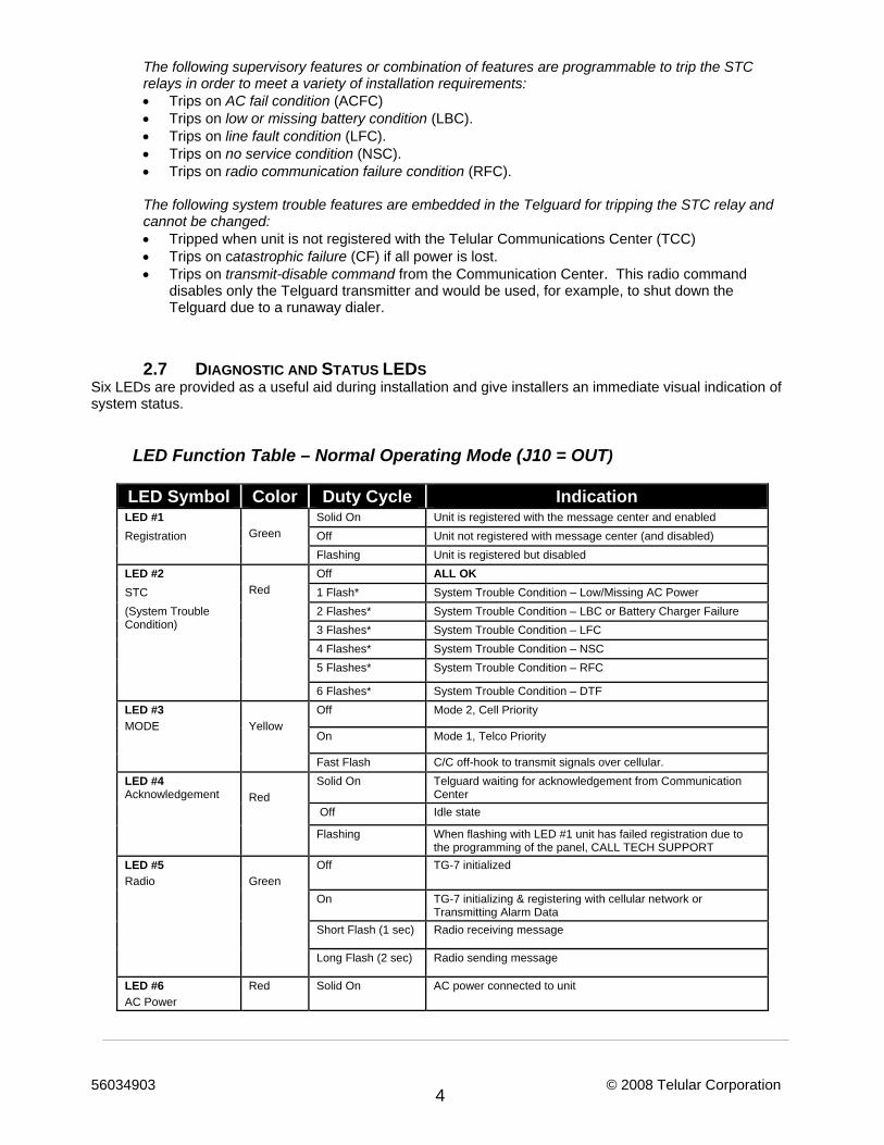
2.7 DIAGNOSTIC AND STATUS LEDS Six LEDs are provided as a useful aid during installation and give installers an immediate visual indication of system status.
LED Function Table – Normal Operating Mode (J10 = OUT)
LED Symbol Color Duty Cycle Indication LED #1
Green Solid On Unit is registered with the message center and enabled
Registration Off Unit not registered with message center (and disabled) Flashing Unit is registered but disabled LED #2
Red
Off ALL OK STC 1 Flash* System Trouble Condition – Low/Missing AC Power (System Trouble Condition)
2 Flashes* System Trouble Condition – LBC or Battery Charger Failure 3 Flashes* System Trouble Condition – LFC 4 Flashes* System Trouble Condition – NSC 5 Flashes* System Trouble Condition – RFC
6 Flashes* System Trouble Condition – DTF LED #3 MODE
Yellow
Off Mode 2, Cell Priority
On Mode 1, Telco Priority
Fast Flash C/C off-hook to transmit signals over cellular. LED #4 Acknowledgement
Red
Solid On Telguard waiting for acknowledgement from Communication Center
Off Idle state
Flashing When flashing with LED #1 unit has failed registration due to the programming of the panel, CALL TECH SUPPORT
LED #5 Radio
Green
Off TG-7 initialized
On TG-7 initializing & registering with cellular network or Transmitting Alarm Data
Short Flash (1 sec) Radio receiving message
Long Flash (2 sec) Radio sending message
LED #6 AC Power
Red Solid On AC power connected to unit
56034903 © 2008 Telular Corporation 5
2.7.1 LED Signal Strength Indication The Telguard provides the installer with an easy to use LED radio signal strength indicator (RSSI) for positioning the unit or remote antenna to obtain the strongest RF signal possible. A signal strength reading can be obtained at any time there is power applied to the Telguard without affecting the operation of the unit. When the “RSSI” jumper J10 is “SHORTED”, the Telguard displays the current received signal strength within 5 seconds. The signal strength is read from bottom to top using the four sequential LEDs located on the top right side of the printed circuit board with the Radio LED #5 = 1 and the STC LED #2 = 4. See Appendix A1.4 for RSSI table.
2.8 TELGUARD SETUP PROGRAMMING PARAMETERS The Telguard will not operate until the unit is activated from the Telular Communication Center. Certain Telguard operating parameters may need to be changed from the factory default programming by the installer during installation. These setting include the STC supervisory trip input settings, CFC settings, NSC/LFC trip delay time, and standby battery size. The Communication Center responds with a radio acknowledgement to the Telguard clearing the STC condition and allowing the Telguard to operate over the cellular radio network. The programmed parameters are transmitted automatically to the Telular Communication Center when the Telguard is activated.
2.9 UL LISTINGS BY MODEL There is a Telguard model designed to meet UL requirements for virtually any residential and commercial burglary/fire installation.
2.9.1 Model TG-7 Model TG-7 and meets the requirements for Household Burglary, Household Fire. They have a standard metal enclosure, key-lock, and a dipole antenna with 12ft. cable. TG-7 is UL Listed for the following: • UL Household Burglary • UL Household Fire • UL Household Burg/Fire Combination
2.9.2 Model TG-7A Model TG-7A meets the requirements for all Household Burglary, Commercial Burglary, and Household Fire. It has an attack-resistant enclosure, key-lock, tamper switch, and a dipole antenna with 12ft. cable. Model TG-7A is UL Listed for the following installations: • UL Household Burglary • UL Household Fire • UL Household Burg/Fire Combination • UL Central Station Burglary • UL Police Connect Burglary • UL Bank, Safe and Vault
56034903 © 2008 Telular Corporation 6
3.0 GETTING READY The Telguard can only be activated when all the necessary accounting information has been entered into the customer database located at the Telular Communication Center. The database includes information about the customer account, unit location, and system test plan information.
3.1 DEALER ACCOUNT ESTABLISHMENT Prior to activation of any Telguard unit, a Dealer Account must be established. Once the Dealer Account has been established and service credit line established between the Security Dealer and Telular, a Cellular Service Activation form may be submitted. Establish your Dealer Account by completing the Telular Cellular Service Dealer Account Application that is included with every Telguard and faxing it to Telular Customer Service at 678-945-1651. Once the application has been completed you will receive an acknowledgment within 1 business day or sooner. This is a one-time event. The acknowledgment from the Telular Technical Service will include a Dealer Account Number that will be used for all Telguard Digital activations.
3.2 SUBSCRIBER ACCOUNT REGISTRATION FOR ACTIVATION A complete Activation Form is required by Telular to register the Telguard prior to leaving for the job site. Activation of the Telguard can be accomplished by either of the two following methods:
1. FAX - Fax the completed Telular Cellular Service Activation Form that is shipped with each Telguard to Telular Customer Service at 678-945-1651.
2. INTERNET - Complete the Activation Form online at www.telular.com.
Within 30 minutes of receipt of the activation request, the subscriber record will be created and the Telguard will be ready for activation. Telular Technical Service is open from 8:00 AM – 8:00 PM EST Monday – Friday 9:00AM-5:00PM EST Saturday and closed during major holidays; Activation requests received after hours will be processed by 9:00 AM EST the next business day.
3.3 PRE-INSTALLATION CHECKLIST Before attempting to connect Telguard to the host C/C, please note the following: 1. Be sure you have all the proper parts before you go to the job site. The following items are shipped with each
Telguard unit:
Activation Form – Complete the Activation Form online at www.telular.com or fax your activation form to Telular Communication Center prior to leaving for the job site.
Telguard unit in metal enclosure. UL Listed plug-in transformer. Antenna with 12’ of cable 3-foot modular plug-to-plug cord for connecting Telguard to RJ31X jack. Telguard Installation and Operating Instructions Manual Backup Battery must be provided by installer
2. You must also have certain installation test tools.
• A standard telephone or lineman's butt-set is required at the job site for use in programming the unit. • Optimal signal strength is determined by placing the unit and antenna where the most LEDs (up to
four) are lighted when using Telguard's on-board Signal Strength Indicator feature so that the unit can be easily placed during installation where signal strength is greatest. Upon location selection, screws and a screw driver will be required to attach the unit and antenna to the wall.
NOTE: Your unit may be subject to airtime charges for unintended use. Telular Cellular Service offers several cellular service rate plans. Check the Activation form that was shipped with your unit or call us to determine what rate plan each unit is operating under.
56034903 © 2008 Telular Corporation 7
4.0 INSTALLATION SUMMARY There are five steps in installing Telguard properly. IF YOU DO NOT PROCEED IN THE ORDER AND MANNER PRESCRIBED, YOU MAY NOT COMPLETE THE INSTALLATION IN THE TIME ALLOCATED. These five steps are summarized below and then explained in detail in the remainder of this manual.
4.1 REGISTER & ACTIVATE THE TELGUARD ON CELLULAR NETWORK Complete the activation form online at www.telular.com or fax the activation form that is included with the product to Telular Communication Center prior to leaving for the job site. Within 30 minutes of receipt of the activation request, the subscriber record will be created and the Telguard will be ready for activation.
4.2 TRANSMIT C/C ALARMS OVER THE TELCO CONNECTION Once you have confirmed that the unit is active, you will be ready to verify that the C/C is programmed properly. This step is important to verify that the C/C is programmed with valid account code and central station information before transmitting signals through the cellular network.
4.3 TRANSMIT C/C ALARMS OVER THE CELLULAR RADIO NETWORK Next, you will be connecting the C/C's digital dialer output to Telguard and verifying that alarm signals can be reliably sent through Telguard over cellular to the central station receiver. The incoming Telco line is not connected to Telguard during this step. NOTE: the first alarm registers the Telguard with the Telular Communication Center and will not be transmitted to the Central Station. All signals after the first are sent to the Central Station.
4.4 CONNECT SUPERVISORY TRIP OUTPUTS Telguard's supervisory trip outputs are connected to the C/C and then tested.
4.5 COMPLETE THE INSTALLATION Your last step will be to check the jumper setting of J10 (LED mode, open = normal), attach earth ground, and permanently mount the unit.
* * * * With this overview of the installation in mind, you should now proceed with the actual installation, following the steps described in the remainder of this manual.
5.0 INSTALLATION STEPS This five-step installation approach (5.1 through 5.5) provides the alarm installer with the easiest and fastest method of properly installing Telguard. Please follow the instructions carefully and if you should need assistance or have any questions, call Telular TECHNICAL SUPPORT at 1-800-229-2326 extension 9. NOTE: Dealer Account Establishment and Cellular Activation must be complete prior to Installation (see section 3.0)
5.1 STEP 1: ACTIVATE & REGISTER THE TELGUARD UNIT
5.1.1 Activate Cellular Service Complete the activation form online at www.Telguard.com or Fax the activation form that is included with the product to Telular Communication Center to activate cellular service. Registration takes place Monday-Friday from 8:00AM to 8:00PM and Saturday 9:00AM to 5:00PM EST. Service registration occurs within 30 minutes of receipt of the activation form. Activation occurs automatically upon transmission of the first alarm signal.
5.1.2 Locate Unit Pick a spot next to the C/C where you think the Telguard will be mounted and place the unit down temporarily in that spot. Do not mount it permanently now, since it may need to be moved to receive a better cellular radio signal or a remote high-gain antenna may be necessary.
56034903 © 2008 Telular Corporation 8
5.1.3 Connect Backup Battery and AC Power Transformer To apply power to Telguard, attach battery leads to battery terminals noting polarity.
Connect the Telguard AC power transformer to AC terminals using stranded copper insulated wire following wire gauge and length recommendations below. Recommended Wire Size Length Not to Exceed 18 ga 20 ft 16 ga 40 ft 14 ga (Max) 60 ft
.
5.1.4 Connect Antenna and Temporarily Place Unit The Telguard is supplied with an antenna. In most cases the antenna may be mounted directly to the Telguard. If a stronger radio signal is required, the antenna must be moved to a better signal location using a Telular antenna cable and bracket accessory (sold separately). The characteristics of the Telguard antenna can be altered depending upon the wall material and materials contained within the wall chosen for mounting. These effects may not be clearly identified by RSSI monitoring alone. The wall materials may have a more profound affect on the antenna’s transmit band performance. When selecting a mounting location, do not mount this unit in an area where the general public could reasonably be within 20cm (8 inches) of the antenna. The supplied dipole antenna is for INDOOR USE ONLY. Note 1: Optimum RF performance can usually be found at the highest point within a building with the fewest number of walls between the Telguard’s antenna and the outside of the premises.
Note 2: To avoid interference with other electronic devices operating in the area, avoid mounting the Telguard’s antenna near other electronic devices.
Note 3: The Telguard Digital TG-7 unit with supplied dipole antenna is designed for indoor installations ONLY. The supplied dipole antenna is for indoor use only.
These considerations should be coupled with the best RSSI indication obtainable (see section 2.7.1). Care should be taken to insure that a large metal object such as a refrigerator or a metal cabinet is not located on the opposite side of the wall. If moving the Telguard to a different location is not practical, then you may need a cable and remote the antenna in order to receive adequate radio signal strength. Pick a high, visually secure spot using the guidelines below. 5.1.4.1 Tips for Improved Radio Signal Reception • The higher the antenna the better. So, start in the drop ceiling above the unit and proceed up from
there, to the roof if necessary. • Remember, the antenna should be as inconspicuous as possible for greatest visual security. • Try to keep the antenna away from sources of RF interference, including pumps, compressors,
ovens, etc., or where metal objects can shield it or otherwise block the cellular radio RF signal. • Place the antenna perpendicular to the ground, either right side up or upside down. Do not mount
the antenna horizontally.
5.1.5 Measure Received Signal Strength for Best Antenna Placement Measure the received signal strength (RSSI) by putting jumper J10 "SHORTED". This switches the LEDs to signal strength mode. Now, slowly move the unit or remote antenna to achieve maximum signal strength. Pick the place where the most LEDs (up to four) are lighted.
56034903 © 2008 Telular Corporation 9
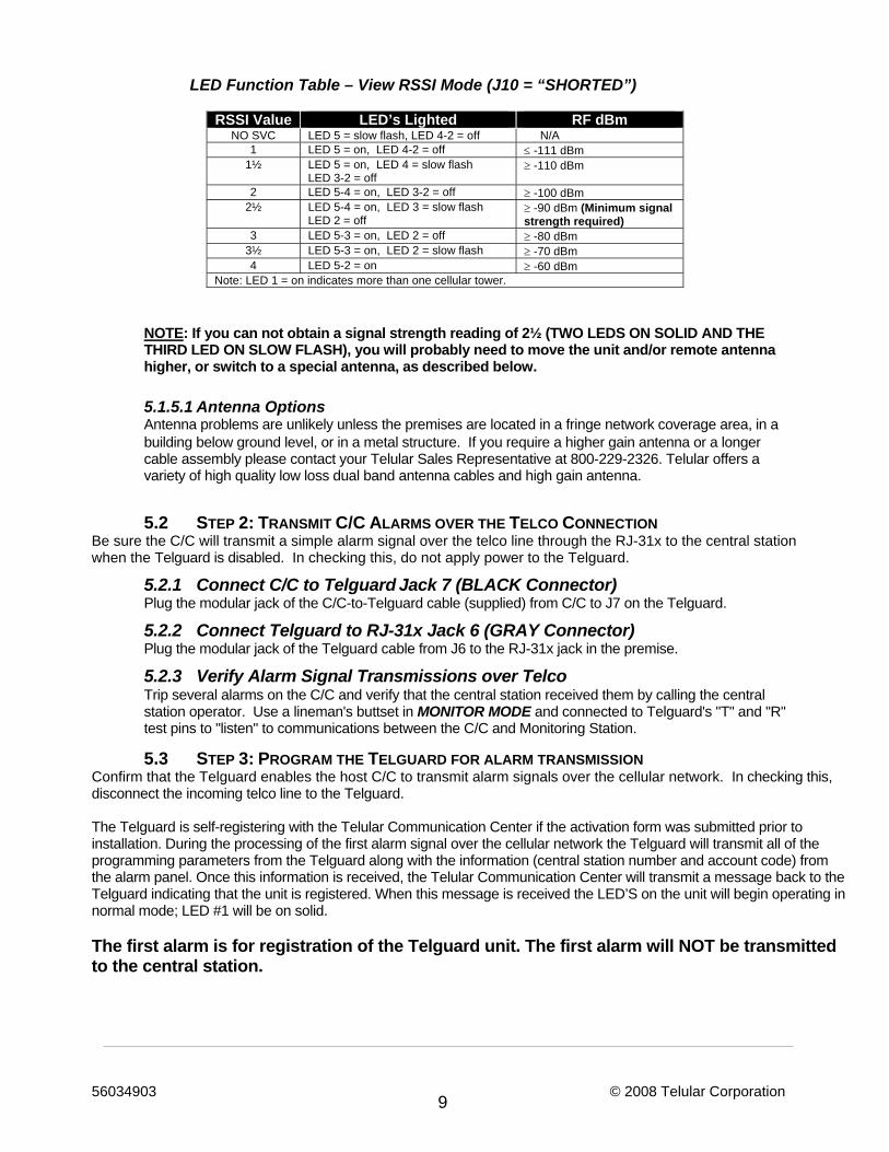
LED Function Table – View RSSI Mode (J10 = “SHORTED”)
RSSI Value LED’s Lighted RF dBm
NO SVC LED 5 = slow flash, LED 4-2 = off N/A 1 LED 5 = on, LED 4-2 = off ≤ -111 dBm
1½ LED 5 = on, LED 4 = slow flash LED 3-2 = off
≥ -110 dBm
2 LED 5-4 = on, LED 3-2 = off ≥ -100 dBm 2½ LED 5-4 = on, LED 3 = slow flash
LED 2 = off ≥ -90 dBm (Minimum signal strength required)
3 LED 5-3 = on, LED 2 = off ≥ -80 dBm 3½ LED 5-3 = on, LED 2 = slow flash ≥ -70 dBm 4 LED 5-2 = on ≥ -60 dBm
Note: LED 1 = on indicates more than one cellular tower.
NOTE: If you can not obtain a signal strength reading of 2½ (TWO LEDS ON SOLID AND THE THIRD LED ON SLOW FLASH), you will probably need to move the unit and/or remote antenna higher, or switch to a special antenna, as described below.
5.1.5.1 Antenna Options Antenna problems are unlikely unless the premises are located in a fringe network coverage area, in a building below ground level, or in a metal structure. If you require a higher gain antenna or a longer cable assembly please contact your Telular Sales Representative at 800-229-2326. Telular offers a variety of high quality low loss dual band antenna cables and high gain antenna.
5.2 STEP 2: TRANSMIT C/C ALARMS OVER THE TELCO CONNECTION Be sure the C/C will transmit a simple alarm signal over the telco line through the RJ-31x to the central station when the Telguard is disabled. In checking this, do not apply power to the Telguard.
5.2.1 Connect C/C to Telguard Jack 7 (BLACK Connector) Plug the modular jack of the C/C-to-Telguard cable (supplied) from C/C to J7 on the Telguard.
5.2.2 Connect Telguard to RJ-31x Jack 6 (GRAY Connector) Plug the modular jack of the Telguard cable from J6 to the RJ-31x jack in the premise.
5.2.3 Verify Alarm Signal Transmissions over Telco Trip several alarms on the C/C and verify that the central station received them by calling the central station operator. Use a lineman's buttset in MONITOR MODE and connected to Telguard's "T" and "R" test pins to "listen" to communications between the C/C and Monitoring Station.
5.3 STEP 3: PROGRAM THE TELGUARD FOR ALARM TRANSMISSION Confirm that the Telguard enables the host C/C to transmit alarm signals over the cellular network. In checking this, disconnect the incoming telco line to the Telguard. The Telguard is self-registering with the Telular Communication Center if the activation form was submitted prior to installation. During the processing of the first alarm signal over the cellular network the Telguard will transmit all of the programming parameters from the Telguard along with the information (central station number and account code) from the alarm panel. Once this information is received, the Telular Communication Center will transmit a message back to the Telguard indicating that the unit is registered. When this message is received the LED’S on the unit will begin operating in normal mode; LED #1 will be on solid. The first alarm is for registration of the Telguard unit. The first alarm will NOT be transmitted to the central station.
56034903 © 2008 Telular Corporation 10
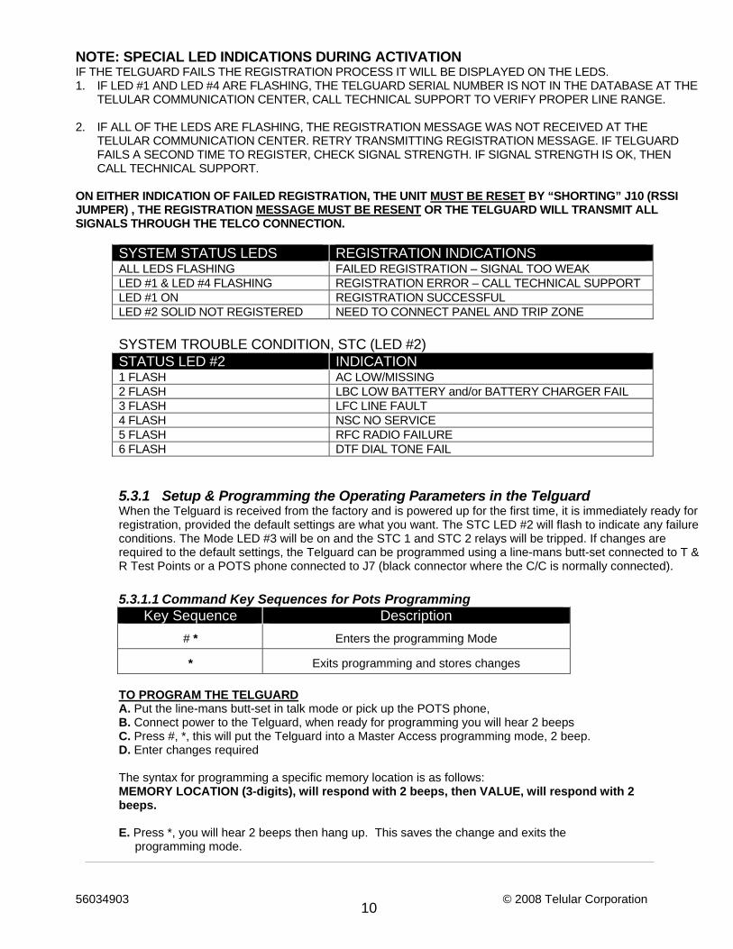
NOTE: SPECIAL LED INDICATIONS DURING ACTIVATION IF THE TELGUARD FAILS THE REGISTRATION PROCESS IT WILL BE DISPLAYED ON THE LEDS. 1. IF LED #1 AND LED #4 ARE FLASHING, THE TELGUARD SERIAL NUMBER IS NOT IN THE DATABASE AT THE
TELULAR COMMUNICATION CENTER, CALL TECHNICAL SUPPORT TO VERIFY PROPER LINE RANGE. 2. IF ALL OF THE LEDS ARE FLASHING, THE REGISTRATION MESSAGE WAS NOT RECEIVED AT THE
TELULAR COMMUNICATION CENTER. RETRY TRANSMITTING REGISTRATION MESSAGE. IF TELGUARD FAILS A SECOND TIME TO REGISTER, CHECK SIGNAL STRENGTH. IF SIGNAL STRENGTH IS OK, THEN CALL TECHNICAL SUPPORT.
ON EITHER INDICATION OF FAILED REGISTRATION, THE UNIT MUST BE RESET BY “SHORTING” J10 (RSSI JUMPER) , THE REGISTRATION MESSAGE MUST BE RESENT OR THE TELGUARD WILL TRANSMIT ALL SIGNALS THROUGH THE TELCO CONNECTION.
SYSTEM STATUS LEDS REGISTRATION INDICATIONS ALL LEDS FLASHING FAILED REGISTRATION – SIGNAL TOO WEAK LED #1 & LED #4 FLASHING REGISTRATION ERROR – CALL TECHNICAL SUPPORT LED #1 ON REGISTRATION SUCCESSFUL LED #2 SOLID NOT REGISTERED NEED TO CONNECT PANEL AND TRIP ZONE SYSTEM TROUBLE CONDITION, STC (LED #2) STATUS LED #2 INDICATION 1 FLASH AC LOW/MISSING 2 FLASH LBC LOW BATTERY and/or BATTERY CHARGER FAIL 3 FLASH LFC LINE FAULT 4 FLASH NSC NO SERVICE 5 FLASH RFC RADIO FAILURE 6 FLASH DTF DIAL TONE FAIL
5.3.1 Setup & Programming the Operating Parameters in the Telguard When the Telguard is received from the factory and is powered up for the first time, it is immediately ready for registration, provided the default settings are what you want. The STC LED #2 will flash to indicate any failure conditions. The Mode LED #3 will be on and the STC 1 and STC 2 relays will be tripped. If changes are required to the default settings, the Telguard can be programmed using a line-mans butt-set connected to T & R Test Points or a POTS phone connected to J7 (black connector where the C/C is normally connected).
5.3.1.1 Command Key Sequences for Pots Programming
Key Sequence Description # * Enters the programming Mode
* Exits programming and stores changes
TO PROGRAM THE TELGUARD A. Put the line-mans butt-set in talk mode or pick up the POTS phone, B. Connect power to the Telguard, when ready for programming you will hear 2 beeps C. Press #, *, this will put the Telguard into a Master Access programming mode, 2 beep. D. Enter changes required
The syntax for programming a specific memory location is as follows: MEMORY LOCATION (3-digits), will respond with 2 beeps, then VALUE, will respond with 2 beeps. E. Press *, you will hear 2 beeps then hang up. This saves the change and exits the
programming mode.
56034903 © 2008 Telular Corporation 11
EXAMPLE To change the Telguard factory default for STC 1 Trip Output reporting from only LFC to include all system trouble conditions the installer would power down the Telguard, connect a butt-set to the T & R test points, reconnect power. Next press #, * the unit will generate 2 beeps. Then press 850, the Telguard will respond with 2 beeps, then press 31, the Telguard will respond with 2 beeps, then press *, you will hear 2 beeps then hang up (this will change STC 1 trip output to report all system trouble conditions). The Telguard will automatically transmit a message to update the Telular Communication Center.
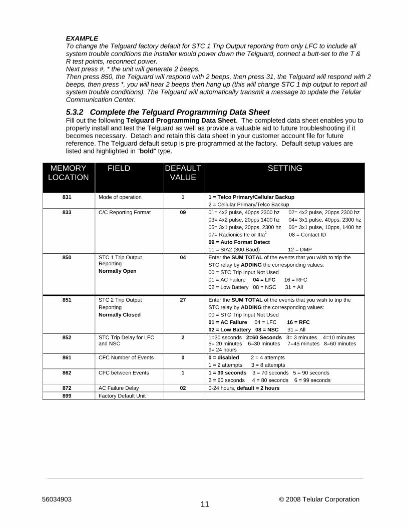
5.3.2 Complete the Telguard Programming Data Sheet Fill out the following Telguard Programming Data Sheet. The completed data sheet enables you to properly install and test the Telguard as well as provide a valuable aid to future troubleshooting if it becomes necessary. Detach and retain this data sheet in your customer account file for future reference. The Telguard default setup is pre-programmed at the factory. Default setup values are listed and highlighted in "bold" type.
MEMORY
LOCATION FIELD DEFAULT
VALUE SETTING
831 Mode of operation 1 1 = Telco Primary/Cellular Backup 2 = Cellular Primary/Telco Backup
833 C/C Reporting Format 09 01= 4x2 pulse, 40pps 2300 hz 02= 4x2 pulse, 20pps 2300 hz 03= 4x2 pulse, 20pps 1400 hz 04= 3x1 pulse, 40pps, 2300 hz 05= 3x1 pulse, 20pps, 2300 hz 06= 3x1 pulse, 10pps, 1400 hz 07= Radionics IIe or IIIa2 08 = Contact ID 09 = Auto Format Detect 11 = SIA2 (300 Baud) 12 = DMP
850 STC 1 Trip Output Reporting Normally Open
04 Enter the SUM TOTAL of the events that you wish to trip the STC relay by ADDING the corresponding values: 00 = STC Trip Input Not Used 01 = AC Failure 04 = LFC 16 = RFC 02 = Low Battery 08 = NSC 31 = All
851 STC 2 Trip Output Reporting Normally Closed
27 Enter the SUM TOTAL of the events that you wish to trip the STC relay by ADDING the corresponding values: 00 = STC Trip Input Not Used 01 = AC Failure 04 = LFC 16 = RFC 02 = Low Battery 08 = NSC 31 = All
852 STC Trip Delay for LFC and NSC
2 1=30 seconds 2=60 Seconds 3= 3 minutes 4=10 minutes 5= 20 minutes 6=30 minutes 7=45 minutes 8=60 minutes 9= 24 hours
861 CFC Number of Events 0 0 = disabled 2 = 4 attempts 1 = 2 attempts 3 = 8 attempts
862 CFC between Events 1 1 = 30 seconds 3 = 70 seconds 5 = 90 seconds 2 = 60 seconds 4 = 80 seconds 6 = 99 seconds
872 AC Failure Delay 02 0-24 hours, default = 2 hours 899 Factory Default Unit
56034903 © 2008 Telular Corporation 12
5.3.3 Disconnect Telguard from RJ-31x Jack Disconnect the Plug from J6 (Gray Connector) of the Telguard that goes to the RJ-31x Jack at the premise.
5.3.4 Verify Alarm Signal Transmissions over Cellular Trip several alarms on the C/C and verify that the central station received them by calling the central station operator. Use a lineman's buttset in MONITOR MODE and connected to Telguard's "T" and "R" test pins to "listen" to communications between the C/C and Telguard. The ACK LED will come on solid while waiting for an acknowledgement.
If you are having problems getting reliable alarm signal transmissions, additional adjustments may be necessary. ♦ Recheck signal strength. You need RSSI = 2½ (TWO LEDS ON SOLID AND THE THIRD LED
FLASHING) for adequate signal strength. Also, check antenna connector and make sure it is seated correctly.
♦ Call Telular Technical Service, 1-800-229-2326 extension 9, and request the Communication Center operator to check the Telguard programming configuration for proper operation and proper communications format.
5.4 STEP 4: CONNECT SUPERVISORY TRIP OUTPUTS Connect and test the supervisory trip outputs to the C/C. NOTE: Activation of a local alarm or strobe light may be desirable when a trip is declared. The STC trip output can be used directly to activate a local signaling device, provided that the trip output is not needed to trip the host control/communicator at the same time. If both a local signal and a control trip input is required, then external relays are needed to provide additional uncommitted contacts. UL Listed installation of the TG-7 will at a minimum have the trip output (STC2) to the host C/C to indicate low A/C (ACFC) and low battery (LBC) conditions.
5.4.1 Decide on a STC Trip Output Strategy The Telguard provides the host C/C with two supervisory trip outputs for reporting a Telguard system trouble code to the central station. The supervisory trip outputs are programmable via a touch-tone telephone or buttset to suit various installation requirements. The programming options for these supervisory trip outputs can be any combination of the following: a. Always Off: Disables all relay supervisory functions. b. ACFC: Trips 2-hours after loss of AC power. Restores 60 seconds after AC power is restored. c. LBC: Trips within 60 seconds on low battery condition. Restores when battery voltage ≥ 12.1 vdc. d. LFC: Trips 30/60-sec. on Telco line fault condition. Restores 30/60 seconds after Telco line restores. e. NSC: Trips 30/60-sec. on no service condition due to loss of RF signal strength. Restores 30/60
seconds after RF signal strength is available. f. RFC: Trips on radio failure to communicate with the Telular Communication Center
5.4.2 Check Telguard Supervisory Trip to C/C After you have connected the STC trip outputs, check to be sure that they operate correctly. 5.4.2.1 Reprogram C/C to Send Proper Code Reprogram C/C, if necessary, to send proper alarm code when tripped by the Telguard’s supervisory output. Program zone restoral as desired.
56034903 © 2008 Telular Corporation 13
5.4.2.2 Check Proper Operation of Telguard Supervisory Output Check for proper operation of each programmed supervisory output by causing it to trip the C/C and be sure the proper LED illuminates and that the proper trouble code is reported to the central station. Skip the testing of any supervisory functions that have not been enabled. Note that the yellow MODE LED #3 starts to flash when the C/C goes off-hook to report the alarm signal over cellular. • Low Battery Condition (LBC): Disconnect the battery and during the next 60 seconds check to see
that the STC LED #2 flashes 2 times indicating that the battery is missing. Check to see that the C/C transmits the STC trouble code (over cellular) to the central station. Reconnect the battery and check during the next 60 seconds to see that the STC LED #2 goes off, indicating the missing battery condition has been restored.
• Line Fault Condition (LFC): Disconnect J/J cable at RJ-11. Check to see that the STC LED #2
flashes 3 times in 30/60 seconds and the C/C transmits the STC trouble code (over cellular) to the central station indicating the incoming telco line is disconnected. Reconnect J/J cable and check to see that the STC LED #2 goes off in 30/60-seconds indicating telco line restoral.
• No Service Condition (NSC): Disconnect the antenna from the Telguard. Check to see that the
STC LED #2 flashes 4 times in 30/60 seconds and the C/C transmits the STC trouble code over the telco line indicating loss of RF signal strength. Reconnect the antenna and check to see that the STC LED #2 goes off in 30/60-seconds indicating RF signal strength restoral. Note: The Received Signal Strength (RSSI) must be less than -114 dBm in order to cause a NSC
condition. If the Telguard is located in a high signal strength area (close to a cellular tower), it is possible for the signal strength to be greater than -114 dBm even with the antenna disconnected.
• AC Fail Condition (ACFC): Disconnect the 12VAC, 10VA transformer and check to see that the AC
POWER LED #6 goes out and the STC LED #2 flashes once indicating that AC power is missing. Reconnect the AC transformer and check to see that the AC POWER LED goes on and the STC LED goes off indicating that AC power has been restored. No transmissions will be sent to the central station. The AC power must be off, continuously, for 2-hours before the STC relay causes the C/C to send a trouble code. If the AC power is restored for 60 seconds or more, then the 2-hour timer restarts.
5.5 STEP 5: COMPLETE THE TELGUARD INSTALLATION Last step is to handle loose ends.
5.5.1 Check Settings Check the jumper setting of J10 (LED mode, “OPEN” = normal, “SHORTED” = RSSI mode).
5.5.2 Permanently Mount and Properly Ground the Telguard Chassis Attach earth ground to the green grounding screw located on lower right-hand corner of printed circuit board assembly and permanently mount the Telguard enclosure. Using the enclosure as a template, mark the top mounting holes on the mounting surface Pre-start the mounting screws (not supplied) for these two holes. Slide the enclosure onto these screws so that the screws move up into the thinner section of the holes. Tighten the screws. Screw in the remaining two screws in the bottom set of mounting holes. Knock out the desired wire entrance on the enclosure.
56034903 © 2008 Telular Corporation 14
A1.0 Appendices
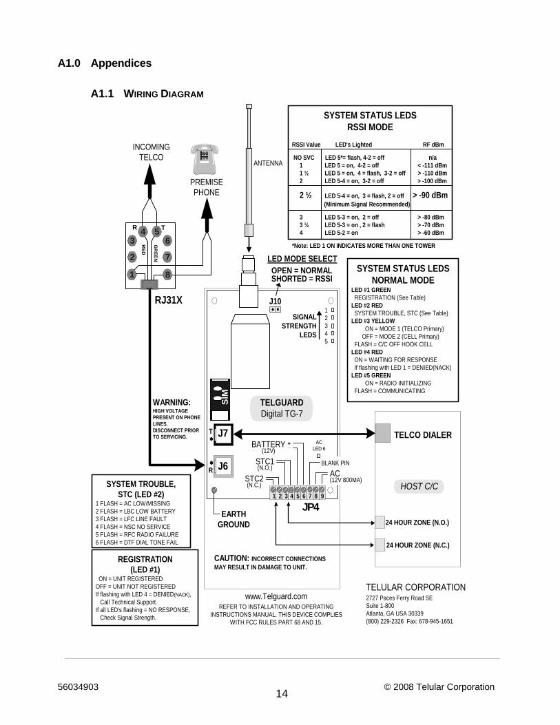
A1.1 WIRING DIAGRAM
24 HOUR ZONE (N.C.)
24 HOUR ZONE (N.O.)
TELCO DIALER
ANTENNA
T
R
1 2 3 4 5 6 7
J6
TELGUARDDigital TG-7
OPEN = NORMAL
SIGNALSTRENGTH
LEDS
PREMISEPHONE
INCOMINGTELCO
RJ31X
www.Telguard.comREFER TO INSTALLATION AND OPERATING
INSTRUCTIONS MANUAL. THIS DEVICE COMPLIESWITH FCC RULES PART 68 AND 15.
TELULAR CORPORATION2727 Paces Ferry Road SESuite 1-800Atlanta, GA USA 30339(800) 229-2326 Fax: 678-945-1651
8 9
+_
JP4
J7
SIM
J10
SHORTED = RSSI
HOST C/C
12345
SYSTEM STATUS LEDSNORMAL MODE
LED #1 GREEN REGISTRATION (See Table)LED #2 RED SYSTEM TROUBLE, STC (See Table)LED #3 YELLOW ON = MODE 1 (TELCO Primary) OFF = MODE 2 (CELL Primary) FLASH = C/C OFF HOOK CELLLED #4 RED ON = WAITING FOR RESPONSE If flashing with LED 1 = DENIED(NACK)LED #5 GREEN ON = RADIO INITIALIZING FLASH = COMMUNICATING
SYSTEM TROUBLE,STC (LED #2)
1 FLASH = AC LOW/MISSING2 FLASH = LBC LOW BATTERY3 FLASH = LFC LINE FAULT4 FLASH = NSC NO SERVICE5 FLASH = RFC RADIO FAILURE6 FLASH = DTF DIAL TONE FAIL
REGISTRATION(LED #1)
ON = UNIT REGISTEREDOFF = UNIT NOT REGISTEREDIf flashing with LED 4 = DENIED(NACK), Call Technical Support.If all LED's flashing = NO RESPONSE, Check Signal Strength.
SYSTEM STATUS LEDSRSSI MODE
RSSI Value LED's Lighted RF dBm
NO SVC LED 5*= flash, 4-2 = off n/a 1 LED 5 = on, 4-2 = off < -111 dBm 1 ½ LED 5 = on, 4 = flash, 3-2 = off > -110 dBm 2 LED 5-4 = on, 3-2 = off > -100 dBm
2 ½ LED 5-4 = on, 3 = flash, 2 = off > -90 dBm (Minimum Signal Recommended)
3 LED 5-3 = on, 2 = off > -80 dBm 3 ½ LED 5-3 = on , 2 = flash > -70 dBm 4 LED 5-2 = on > -60 dBm
*Note: LED 1 ON INDICATES MORE THAN ONE TOWER
ACLED 6
CAUTION: INCORRECT CONNECTIONSMAY RESULT IN DAMAGE TO UNIT.
WARNING:HIGH VOLTAGEPRESENT ON PHONELINES.DISCONNECT PRIORTO SERVICING.
LED MODE SELECT
EARTHGROUND
STC2(N.C.)
STC1(N.O.)
BATTERY(12V)
BLANK PIN
AC(12V 800MA)
GR
EEN
R T
RED
1
2 7
8
3 64 5
56034903 © 2008 Telular Corporation 15
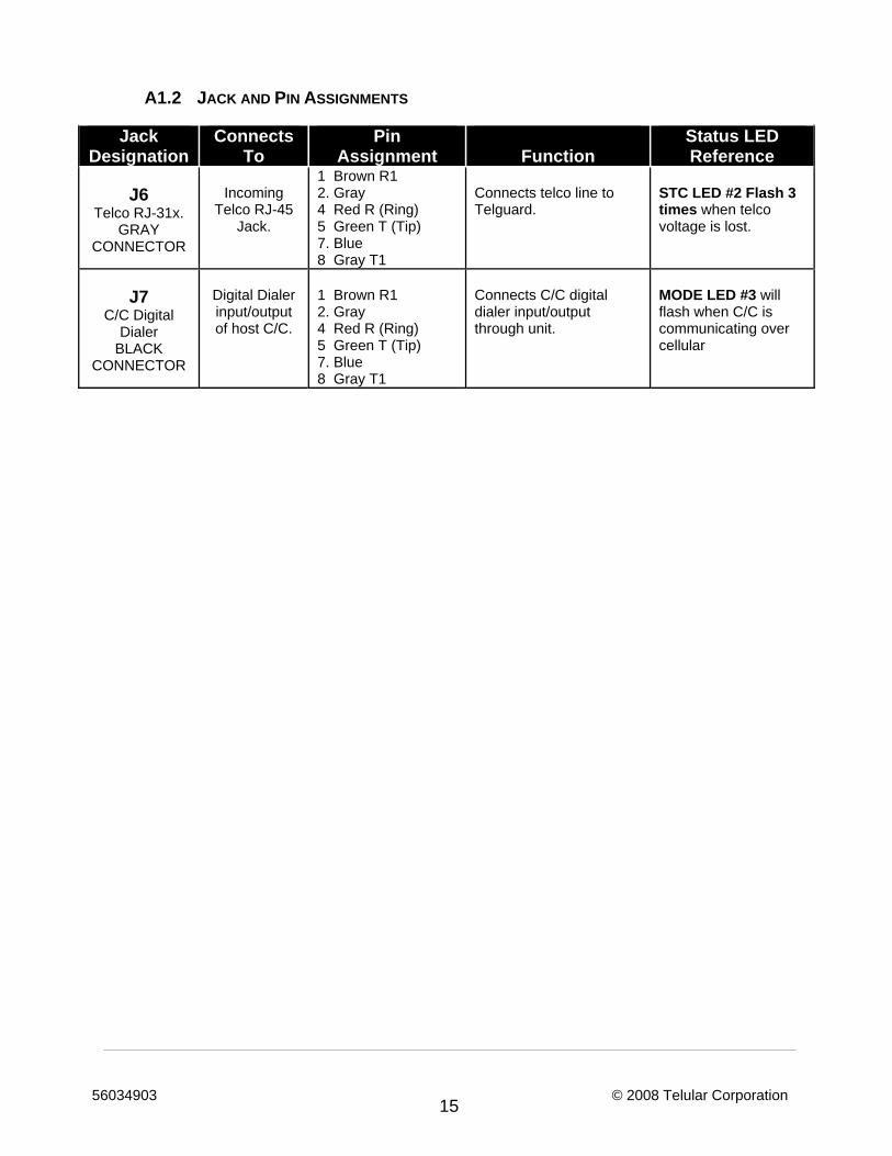
A1.2 JACK AND PIN ASSIGNMENTS
Jack Designation
Connects To
Pin Assignment
Function
Status LED Reference
J6
Telco RJ-31x. GRAY
CONNECTOR
Incoming
Telco RJ-45 Jack.
1 Brown R1 2. Gray 4 Red R (Ring) 5 Green T (Tip) 7. Blue 8 Gray T1
Connects telco line to Telguard.
STC LED #2 Flash 3 times when telco voltage is lost.
J7
C/C Digital Dialer
BLACK CONNECTOR
Digital Dialer input/output of host C/C.
1 Brown R1 2. Gray 4 Red R (Ring) 5 Green T (Tip) 7. Blue 8 Gray T1
Connects C/C digital dialer input/output through unit.
MODE LED #3 will flash when C/C is communicating over cellular
56034903 © 2008 Telular Corporation 16
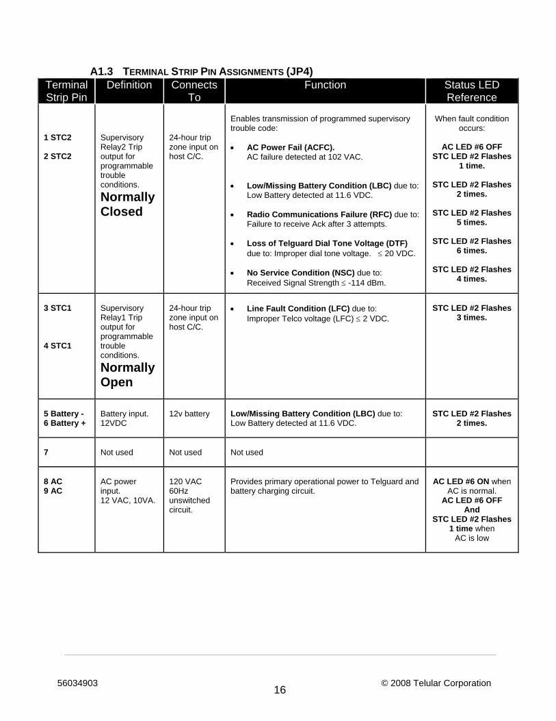
A1.3 TERMINAL STRIP PIN ASSIGNMENTS (JP4) Terminal Strip Pin
Definition Connects To
Function Status LED Reference
1 STC2 2 STC2
Supervisory Relay2 Trip output for programmable trouble conditions.
Normally Closed
24-hour trip zone input on host C/C.
Enables transmission of programmed supervisory trouble code: • AC Power Fail (ACFC).
AC failure detected at 102 VAC. • Low/Missing Battery Condition (LBC) due to:
Low Battery detected at 11.6 VDC. • Radio Communications Failure (RFC) due to:
Failure to receive Ack after 3 attempts. • Loss of Telguard Dial Tone Voltage (DTF)
due to: Improper dial tone voltage. ≤ 20 VDC. • No Service Condition (NSC) due to:
Received Signal Strength ≤ -114 dBm.
When fault condition
occurs:
AC LED #6 OFF STC LED #2 Flashes
1 time.
STC LED #2 Flashes 2 times.
STC LED #2 Flashes
5 times.
STC LED #2 Flashes 6 times.
STC LED #2 Flashes
4 times.
3 STC1 4 STC1
Supervisory Relay1 Trip output for programmable trouble conditions.
Normally Open
24-hour trip zone input on host C/C.
• Line Fault Condition (LFC) due to:
Improper Telco voltage (LFC) ≤ 2 VDC.
STC LED #2 Flashes 3 times.
5 Battery - 6 Battery +
Battery input. 12VDC
12v battery Low/Missing Battery Condition (LBC) due to:
Low Battery detected at 11.6 VDC. STC LED #2 Flashes
2 times.
7
Not used
Not used
Not used
8 AC 9 AC
AC power input. 12 VAC, 10VA.
120 VAC 60Hz unswitched circuit.
Provides primary operational power to Telguard and battery charging circuit.
AC LED #6 ON when AC is normal.
AC LED #6 OFF And
STC LED #2 Flashes 1 time when
AC is low
56034903 © 2008 Telular Corporation 17
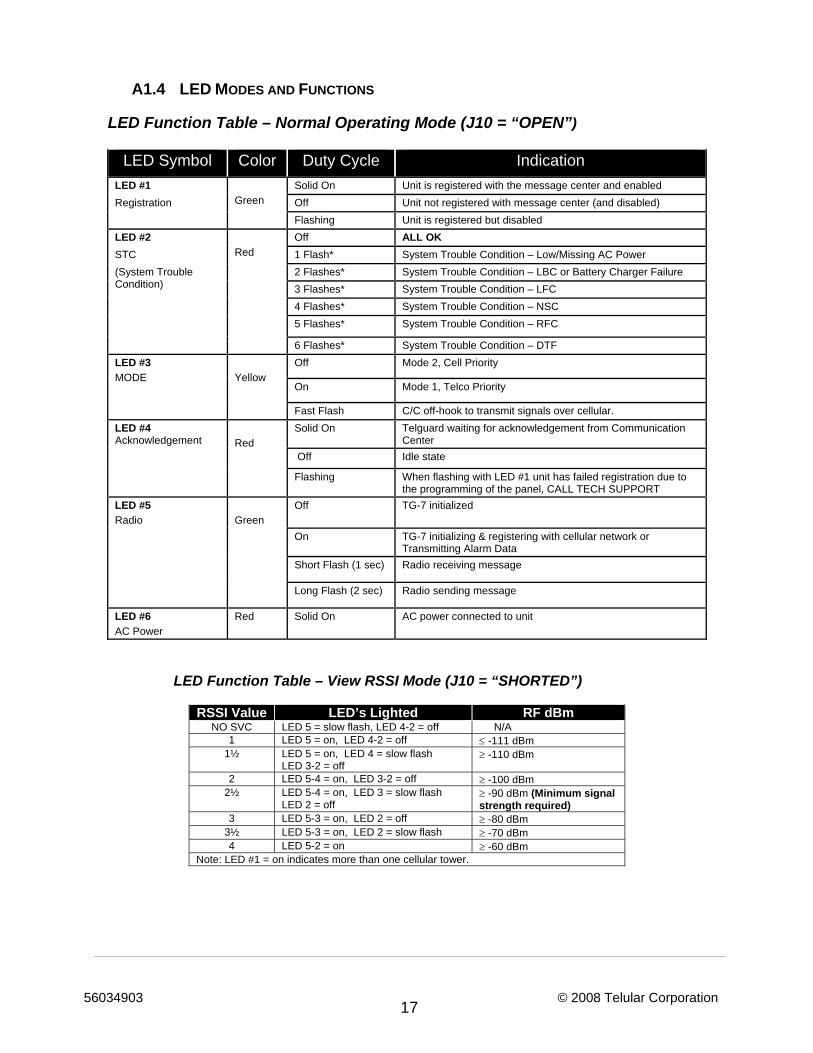
A1.4 LED MODES AND FUNCTIONS
LED Function Table – Normal Operating Mode (J10 = “OPEN”)
LED Symbol Color Duty Cycle Indication LED #1
Green Solid On Unit is registered with the message center and enabled
Registration Off Unit not registered with message center (and disabled) Flashing Unit is registered but disabled LED #2
Red
Off ALL OK STC 1 Flash* System Trouble Condition – Low/Missing AC Power (System Trouble Condition)
2 Flashes* System Trouble Condition – LBC or Battery Charger Failure 3 Flashes* System Trouble Condition – LFC 4 Flashes* System Trouble Condition – NSC 5 Flashes* System Trouble Condition – RFC
6 Flashes* System Trouble Condition – DTF LED #3 MODE
Yellow
Off Mode 2, Cell Priority
On Mode 1, Telco Priority
Fast Flash C/C off-hook to transmit signals over cellular. LED #4 Acknowledgement
Red
Solid On Telguard waiting for acknowledgement from Communication Center
Off Idle state
Flashing When flashing with LED #1 unit has failed registration due to the programming of the panel, CALL TECH SUPPORT
LED #5 Radio
Green
Off TG-7 initialized
On TG-7 initializing & registering with cellular network or Transmitting Alarm Data
Short Flash (1 sec) Radio receiving message
Long Flash (2 sec) Radio sending message
LED #6 AC Power
Red Solid On AC power connected to unit
LED Function Table – View RSSI Mode (J10 = “SHORTED”)
RSSI Value LED’s Lighted RF dBm
NO SVC LED 5 = slow flash, LED 4-2 = off N/A 1 LED 5 = on, LED 4-2 = off ≤ -111 dBm
1½ LED 5 = on, LED 4 = slow flash LED 3-2 = off
≥ -110 dBm
2 LED 5-4 = on, LED 3-2 = off ≥ -100 dBm 2½ LED 5-4 = on, LED 3 = slow flash
LED 2 = off ≥ -90 dBm (Minimum signal strength required)
3 LED 5-3 = on, LED 2 = off ≥ -80 dBm 3½ LED 5-3 = on, LED 2 = slow flash ≥ -70 dBm 4 LED 5-2 = on ≥ -60 dBm
Note: LED #1 = on indicates more than one cellular tower.
56034903 © 2008 Telular Corporation 18
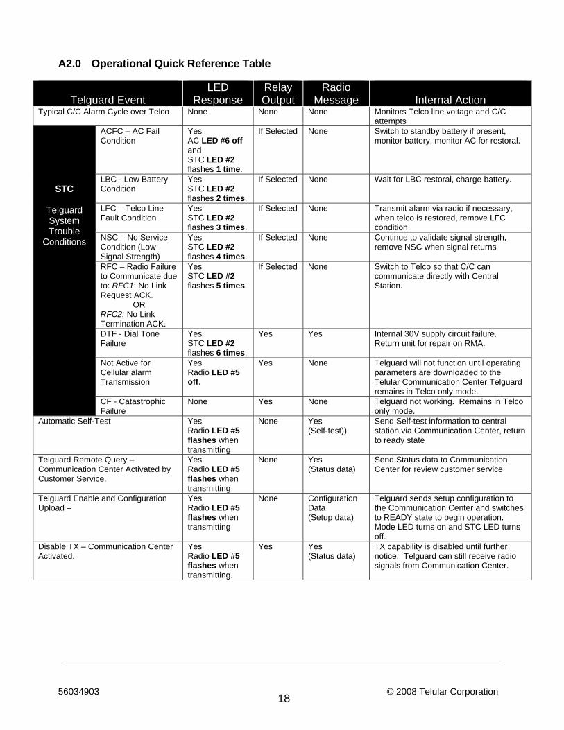
A2.0 Operational Quick Reference Table
Telguard Event
LED Response
Relay Output
Radio Message
Internal Action
Typical C/C Alarm Cycle over Telco None None None Monitors Telco line voltage and C/C attempts
STC
Telguard System Trouble
Conditions
ACFC – AC Fail Condition
Yes AC LED #6 off and STC LED #2 flashes 1 time.
If Selected None Switch to standby battery if present, monitor battery, monitor AC for restoral.
LBC - Low Battery Condition
Yes STC LED #2 flashes 2 times.
If Selected None Wait for LBC restoral, charge battery.
LFC – Telco Line Fault Condition
Yes STC LED #2 flashes 3 times.
If Selected None Transmit alarm via radio if necessary, when telco is restored, remove LFC condition
NSC – No Service Condition (Low Signal Strength)
Yes STC LED #2 flashes 4 times.
If Selected None Continue to validate signal strength, remove NSC when signal returns
RFC – Radio Failure to Communicate due to: RFC1: No Link Request ACK.
OR RFC2: No Link Termination ACK.
Yes STC LED #2 flashes 5 times.
If Selected None Switch to Telco so that C/C can communicate directly with Central Station.
DTF - Dial Tone Failure
Yes STC LED #2 flashes 6 times.
Yes Yes Internal 30V supply circuit failure. Return unit for repair on RMA.
Not Active for Cellular alarm Transmission
Yes Radio LED #5 off.
Yes None Telguard will not function until operating parameters are downloaded to the Telular Communication Center Telguard remains in Telco only mode.
CF - Catastrophic Failure
None Yes None Telguard not working. Remains in Telco only mode.
Automatic Self-Test Yes Radio LED #5 flashes when transmitting
None Yes (Self-test))
Send Self-test information to central station via Communication Center, return to ready state
Telguard Remote Query – Communication Center Activated by Customer Service.
Yes Radio LED #5 flashes when transmitting
None Yes (Status data)
Send Status data to Communication Center for review customer service
Telguard Enable and Configuration Upload –
Yes Radio LED #5 flashes when transmitting
None Configuration Data (Setup data)
Telguard sends setup configuration to the Communication Center and switches to READY state to begin operation. Mode LED turns on and STC LED turns off.
Disable TX – Communication Center Activated.
Yes Radio LED #5 flashes when transmitting.
Yes Yes (Status data)
TX capability is disabled until further notice. Telguard can still receive radio signals from Communication Center.
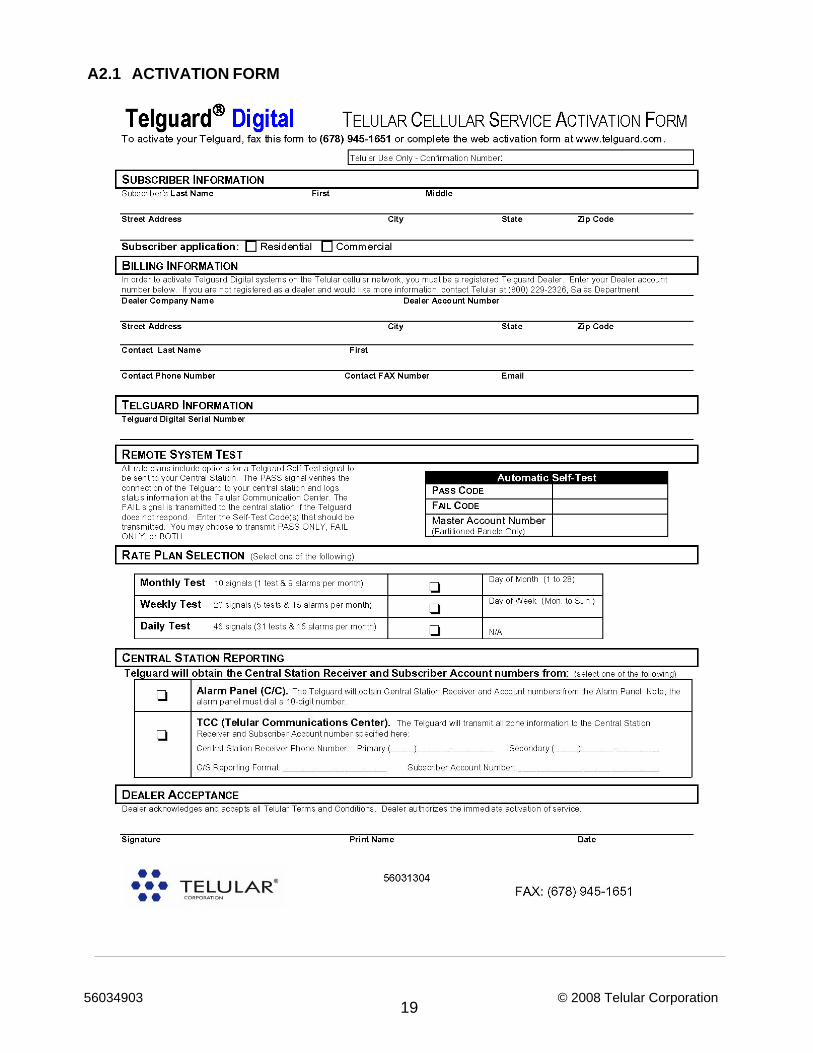
56034903 © 2008 Telular Corporation 19
A2.1 ACTIVATION FORM
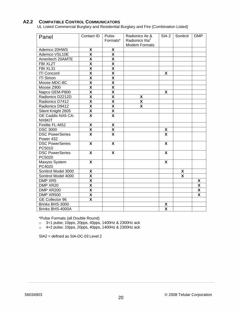
56034903 © 2008 Telular Corporation 20
A2.2 COMPATIBLE CONTROL COMMUNICATORS UL Listed Commercial Burglary and Residential Burglary and Fire (Combination Listed) Panel Contact ID Pulse
Formats* Radionics IIe & Radionics IIIa2
Modem Formats
SIA 2 Sonitrol DMP
Ademco 20HWS X X Ademco VSL10E X X Ameritech 20AMTE X X FBI XL2T X X FBI XL31 X X ITI Concord X X X ITI Simon X X Moose MDC-8C X X Moose Z900 X X Napco GEM-P800 X X X Radionics D2212D X X X Radionics D7412 X X X Radionics D9412 X X X Silent Knight 2605 X X GE Caddix NX6 CA-NX6KIT
X X
Firelite FL-MS2 X X DSC 3000 X X X DSC PowerSeries Power 432
X X X
DSC PowerSeries PC5010
X X X
DSC PowerSeries PC5020
X X X
Maxyss System PC4020
X X
Sonitrol Model 3000 X X Sonitrol Model 4000 X X DMP XR5 X X DMP XR20 X X DMP XR200 X X DMP XR500 X X GE Collector 96 X Brinks BHS-3000 X Brinks BHS-4000A X
*Pulse Formats (all Double Round) o 3+1 pulse; 10pps, 20pps, 40pps, 1400Hz & 2300Hz ack o 4+2 pulse; 10pps, 20pps, 40pps, 1400Hz & 2300Hz ack SIA2 = defined as SIA-DC-03 Level 2
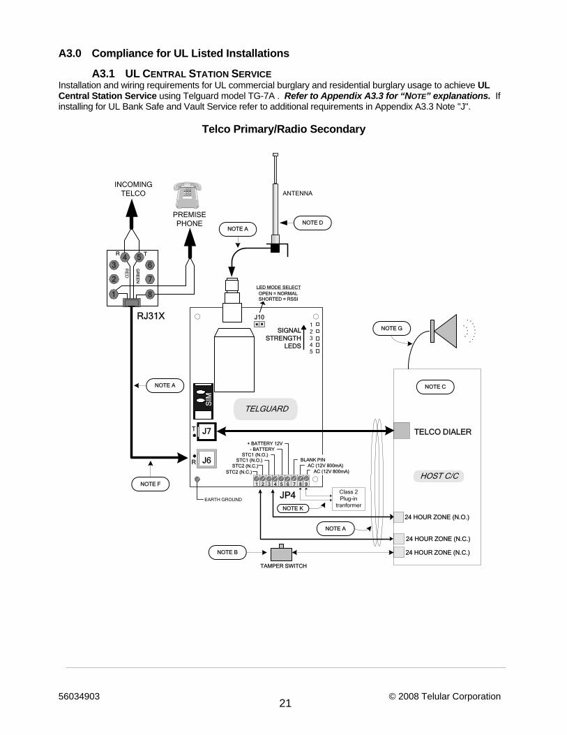
56034903 © 2008 Telular Corporation 21
A3.0 Compliance for UL Listed Installations
A3.1 UL CENTRAL STATION SERVICE Installation and wiring requirements for UL commercial burglary and residential burglary usage to achieve UL Central Station Service using Telguard model TG-7A . Refer to Appendix A3.3 for “NOTE” explanations. If installing for UL Bank Safe and Vault Service refer to additional requirements in Appendix A3.3 Note "J".
Telco Primary/Radio Secondary
24 HOUR ZONE (N.C.)
24 HOUR ZONE (N.O.)
TELCO DIALER
ANTENNA
LED MODE SELECT
T
R
STC2 (N.C.)STC2 (N.C.)
STC1 (N.O.)STC1 (N.O.)
AC (12V 800mA)AC (12V 800mA)
BLANK PINJ6
EARTH GROUND
TELGUARD
OPEN = NORMAL
SIGNALSTRENGTH
LEDS
GR
EE
N
R T
RE
D
PREMISEPHONE
INCOMINGTELCO
RJ31X
+ BATTERY 12V- BATTERY
JP4
J7
SIM
J10
SHORTED = RSSI
HOST C/C
12345
NOTE ANOTE D
NOTE A
NOTE A
NOTE F
NOTE C
NOTE B
TAMPER SWITCH
NOTE G
1 2 3 4 5 6 7 8 9
Class 2 Plug-in
tranformer
24 HOUR ZONE (N.C.)
NOTE K
1
2 7
8
3 64 5
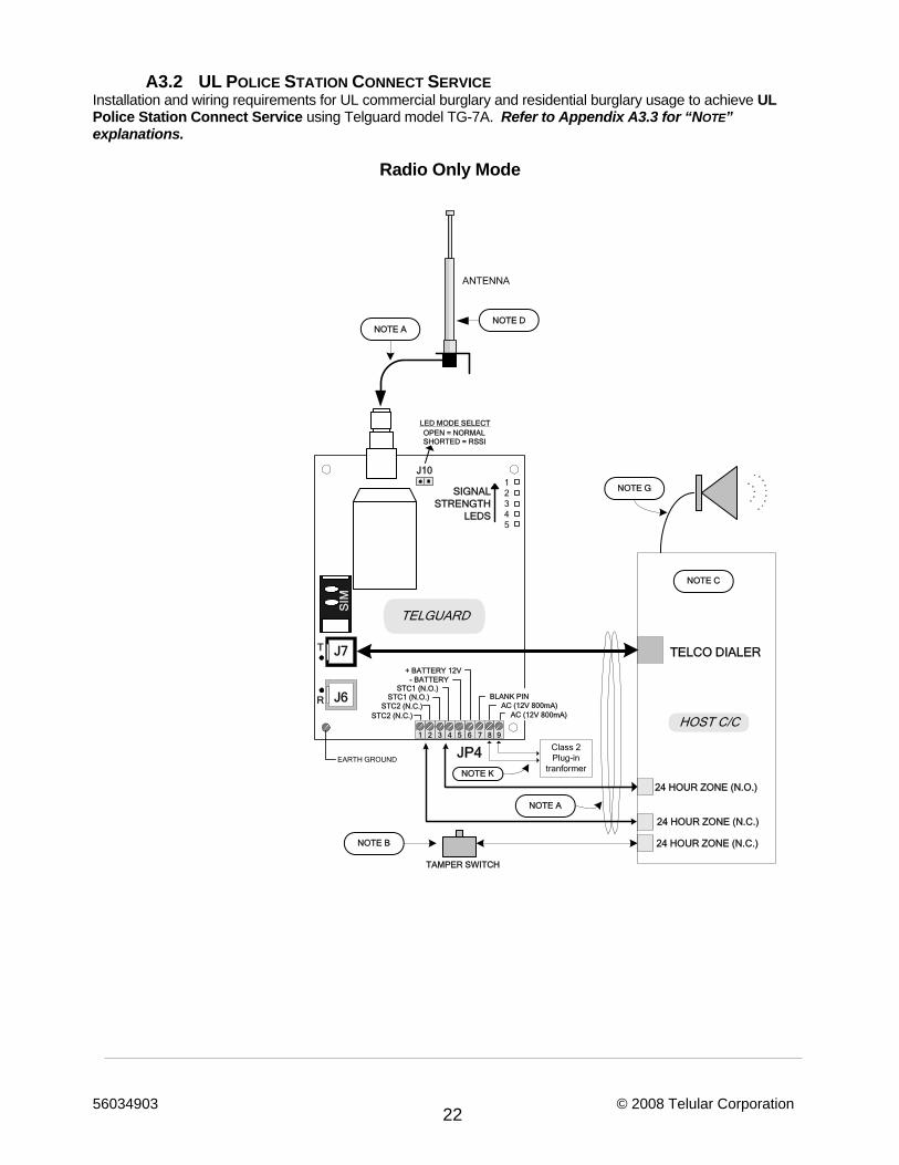
56034903 © 2008 Telular Corporation 22
A3.2 UL POLICE STATION CONNECT SERVICE Installation and wiring requirements for UL commercial burglary and residential burglary usage to achieve UL Police Station Connect Service using Telguard model TG-7A. Refer to Appendix A3.3 for “NOTE” explanations.
Radio Only Mode
24 HOUR ZONE (N.C.)
24 HOUR ZONE (N.O.)
TELCO DIALER
ANTENNA
LED MODE SELECT
T
R
STC2 (N.C.)STC2 (N.C.)
STC1 (N.O.)STC1 (N.O.)
AC (12V 800mA)AC (12V 800mA)
BLANK PINJ6
EARTH GROUND
TELGUARD
OPEN = NORMAL
SIGNALSTRENGTH
LEDS
+ BATTERY 12V- BATTERY
JP4
J7
SIM
J10
SHORTED = RSSI
HOST C/C
12345
NOTE ANOTE D
NOTE A
NOTE C
NOTE B
TAMPER SWITCH
NOTE G
1 2 3 4 5 6 7 8 9
Class 2 Plug-in
tranformer
24 HOUR ZONE (N.C.)
NOTE K
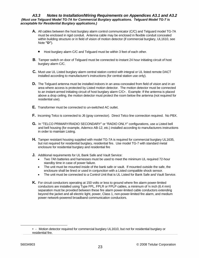
56034903 © 2008 Telular Corporation 23
A3.3 Notes to Installation/Wiring Requirements on Appendices A3.1 and A3.2 (Must use Telguard Model TG-7A for Commercial Burglary applications. Telguard Model TG-7 is acceptable for Residential Burglary applications.)
A. All cables between the host burglary alarm control communicator (C/C) and Telguard model TG-7A
must be enclosed in rigid conduit. Antenna cable may be enclosed in flexible conduit concealed within building structure or in field of vision of motion detector (if commercial burglary, UL1610, see Note ”D”).
• Host burglary alarm C/C and Telguard must be within 3 feet of each other.
B. Tamper switch on door of Telguard must be connected to instant 24 hour initiating circuit of host
burglary alarm C/C. C. Must use UL Listed burglary alarm central station control with integral or UL listed remote DACT
installed according to manufacturer's instructions (for central station use only). D. The Telguard antenna must be installed indoors in an area concealed from field of vision and in an
area where access is protected by Listed motion detector. The motion detector must be connected to an instant-armed initiating circuit of host burglary alarm C/C∗. Example: If the antenna is placed above a drop ceiling, the motion detector must protect the room below the antenna (not required for residential use).
E. Transformer must be connected to un-switched AC outlet. F. Incoming Telco is connected to J6 (gray connector). Direct Telco line connection required. No PBX. G. In “TELCO PRIMARY/RADIO SECONDARY” or “RADIO ONLY” configurations, use a Listed bell
and bell housing (for example, Ademco AB-12, etc.) installed according to manufacturers instructions in order to maintain Listing.
H. Tamper resistant housing supplied with model TG-7A is required for commercial burglary UL1635,
but not required for residential burglary, residential fire. Use model TG-7 with standard metal enclosure for residential burglary and residential fire
J. Additional requirements for UL Bank Safe and Vault Service:
• Two 7Ah batteries and harnesses must be used to meet the minimum UL required 72-hour standby time in case of power failure.
• The unit must be mounted inside of the bank safe or vault. If mounted outside the safe, the enclosure shall be lined or used in conjunction with a Listed compatible shock sensor.
• The unit must be connected to a Control Unit that is UL Listed for Bank Safe and Vault Service. K. For circuit conductors operating at 150 volts or less to ground where fire alarm power-limited
conductors are installed using Type FPL, FPLR or FPLP cables, a minimum of ¼ inch (6.4 mm) separation must be provided between these fire alarm power-limited cable conductors extending beyond the jacket and all electric light, power, Class 1, non-power-limited fire alarm, and medium power network-powered broadband communication conductors.
∗ - Motion detector required for commercial burglary UL1610, but not for residential burglary or residential fire.
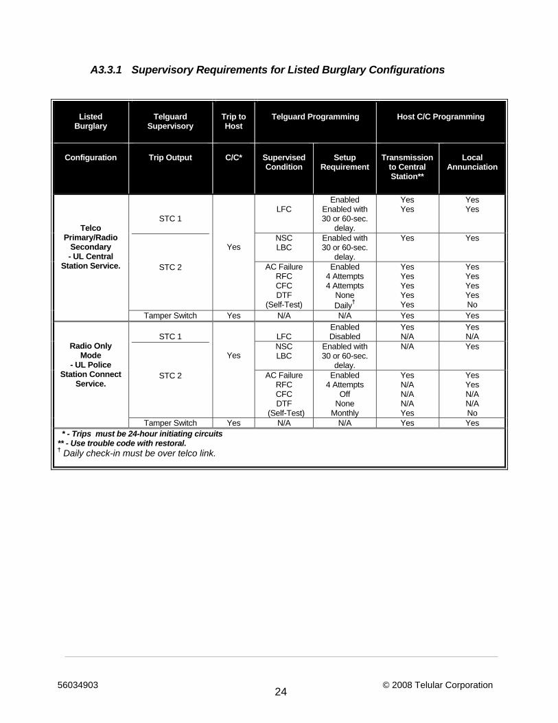
56034903 © 2008 Telular Corporation 24
A3.3.1 Supervisory Requirements for Listed Burglary Configurations
Listed Burglary
Telguard
Supervisory
Trip to Host
Telguard Programming Host C/C Programming
Configuration
Trip Output C/C* Supervised
Condition Setup
Requirement
Transmission
to Central Station**
Local Annunciation
Telco Primary/Radio
Secondary - UL Central
Station Service.
STC 1
STC 2
Yes
LFC
Enabled Enabled with 30 or 60-sec.
delay.
Yes Yes
Yes Yes
NSC LBC
Enabled with 30 or 60-sec.
delay.
Yes Yes
AC Failure RFC CFC DTF
(Self-Test)
Enabled 4 Attempts 4 Attempts
None Daily†
Yes Yes Yes Yes Yes
Yes Yes Yes Yes No
Tamper Switch Yes N/A N/A Yes Yes
Radio Only Mode
- UL Police Station Connect
Service.
STC 1
STC 2
Yes
LFC
Enabled Disabled
Yes N/A
Yes N/A
NSC LBC
Enabled with 30 or 60-sec.
delay.
N/A Yes
AC Failure RFC CFC DTF
(Self-Test)
Enabled 4 Attempts
Off None
Monthly
Yes N/A N/A N/A Yes
Yes Yes N/A N/A No
Tamper Switch Yes N/A N/A Yes Yes * - Trips must be 24-hour initiating circuits ** - Use trouble code with restoral. † Daily check-in must be over telco link.
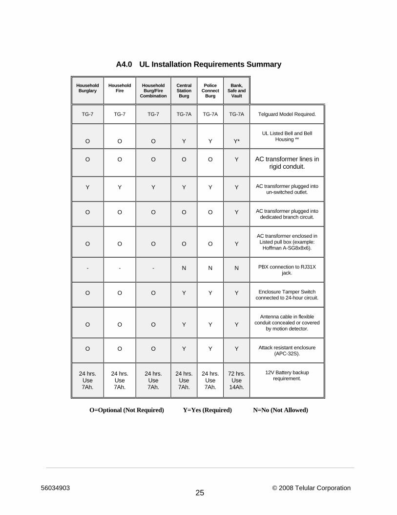
56034903 © 2008 Telular Corporation 25
A4.0 UL Installation Requirements Summary
Household Burglary
Household
Fire
Household Burg/Fire
Combination
Central Station Burg
Police
Connect Burg
Bank,
Safe and Vault
TG-7
TG-7
TG-7
TG-7A
TG-7A
TG-7A
Telguard Model Required.
O
O
O
Y
Y
Y*
UL Listed Bell and Bell
Housing **
O
O
O
O
O
Y
AC transformer lines in
rigid conduit.
Y
Y
Y
Y
Y
Y
AC transformer plugged into
un-switched outlet.
O
O
O
O
O
Y
AC transformer plugged into
dedicated branch circuit.
O
O
O
O
O
Y
AC transformer enclosed in Listed pull box (example:
Hoffman A-SG8x8x6).
-
-
-
N
N
N
PBX connection to RJ31X
jack.
O
O
O
Y
Y
Y
Enclosure Tamper Switch
connected to 24-hour circuit.
O
O
O
Y
Y
Y
Antenna cable in flexible
conduit concealed or covered by motion detector.
O
O
O
Y
Y
Y
Attack resistant enclosure (APC-32S).
24 hrs. Use 7Ah.
24 hrs.
Use 7Ah.
24 hrs.
Use 7Ah.
24 hrs.
Use 7Ah.
24 hrs.
Use 7Ah.
72 hrs.
Use 14Ah.
12V Battery backup
requirement.
O=Optional (Not Required) Y=Yes (Required) N=No (Not Allowed)
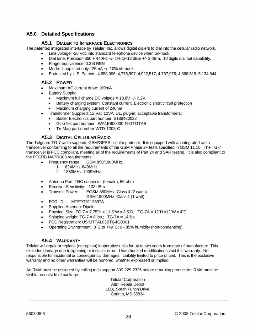
56034903 © 2008 Telular Corporation 26
A5.0 Detailed Specifications A5.1 DIALER TO INTERFACE ELECTRONICS
The patented integrated interface by Telular, Inc. allows digital dialers to dial into the cellular radio network. • Line voltage: -26 Vdc into standard telephone device when on-hook. • Dial tone: Precision 350 + 440Hz +/- 1% @-13 dBm +/- 2 dBm. 10 digits dial out capability. • Ringer equivalence: 0.3 B REN • Mode: Loop start only. 25mA +/- 10% off-hook. • Protected by U.S. Patents: 4,658,096; 4,775,997; 4,922,517; 4,737,975; 4,868,519; 5,134,644.
A5.2 POWER • Maximum AC current draw: 100mA • Battery Supply:
• Maximum full charge DC voltage = 13.8V +/- 0.2V. • Battery charging system: Constant current, Electronic short circuit protection • Maximum charging current of 240ma
• Transformer Supplied: 12 Vac 10VA, UL, plug-in; acceptable transformers: • Basler Electronics part number: S189480032 • GlobTek part number: WA1E800J00-N-GTGTAB • Tri-Mag part number WTD-1208-C
A5.3 DIGITAL CELLULAR RADIO The Telguard TG-7 radio supports GSM/GPRS cellular protocol. It is equipped with an integrated radio transceiver conforming to all the requirements of the GSM Phase 2+ tests specified in GSM 11.10. The TG-7 transceiver is FCC compliant, meeting all of the requirements of Part 24 and SAR testing. It is also compliant to the PTCRB NAPRD03 requirements.
• Frequency range: GSM 850/1900MHz, 1. 824MHz-849MHz 2. 1850MHz-1909MHz
• Antenna Port: TNC connector (female), 50-ohm • Receiver Sensitivity: -102 dBm • Transmit Power: EGSM 850MHz: Class 4 (2 watts)
GSM 1900MHz: Class 1 (1 watt) • FCC I.D.: MTFTG5112597A • Supplied Antenna: Dipole • Physical Size: TG-7 = 7.75"H x 11.5"W x 3.5"D; TG-7A = 12”H x12”W x 4”D. • Shipping weight: TG-7 = 8 lbs.; TG-7A = 14 lbs. • FCC Registration: US:MTFAL03BTG4G0001 • Operating Environment: 0° C to +49° C; 0 - 85% humidity (non-condensing).
A5.4 WARRANTY Telular will repair or replace (our option) inoperative units for up to two years from date of manufacture. This excludes damage due to lightning or installer error. Unauthorized modifications void this warranty. Not responsible for incidental or consequential damages. Liability limited to price of unit. This is the exclusive warranty and no other warranties will be honored, whether expressed or implied. An RMA must be assigned by calling tech support 800-229-2326 before returning product to: RMA must be visible on outside of package.
Telular Corporation Attn: Repair Depot
1801 South Fulton Drive Corinth, MS 38834
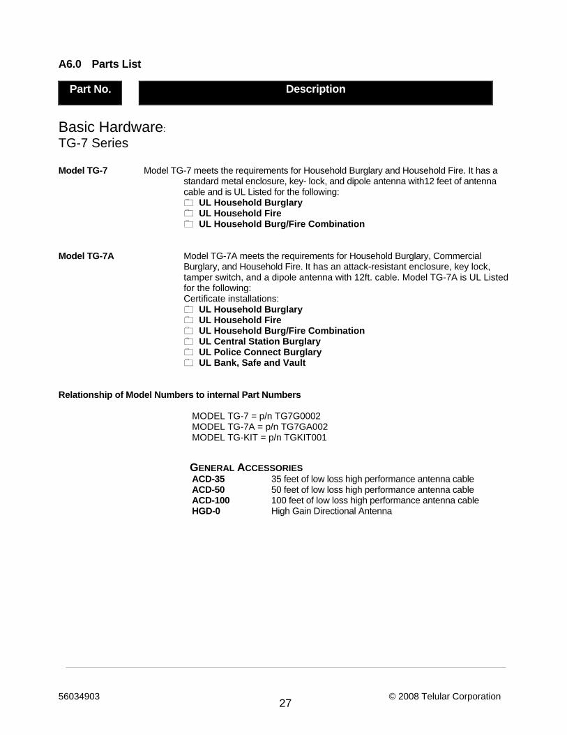
56034903 © 2008 Telular Corporation 27
A6.0 Parts List Part No. Description
Basic Hardware: TG-7 Series Model TG-7 Model TG-7 meets the requirements for Household Burglary and Household Fire. It has a
standard metal enclosure, key- lock, and dipole antenna with12 feet of antenna cable and is UL Listed for the following:
UL Household Burglary UL Household Fire UL Household Burg/Fire Combination
Model TG-7A Model TG-7A meets the requirements for Household Burglary, Commercial
Burglary, and Household Fire. It has an attack-resistant enclosure, key lock, tamper switch, and a dipole antenna with 12ft. cable. Model TG-7A is UL Listed for the following:
Certificate installations: UL Household Burglary UL Household Fire UL Household Burg/Fire Combination UL Central Station Burglary UL Police Connect Burglary UL Bank, Safe and Vault
Relationship of Model Numbers to internal Part Numbers
MODEL TG-7 = p/n TG7G0002 MODEL TG-7A = p/n TG7GA002 MODEL TG-KIT = p/n TGKIT001
GENERAL ACCESSORIES ACD-35 35 feet of low loss high performance antenna cable ACD-50 50 feet of low loss high performance antenna cable ACD-100 100 feet of low loss high performance antenna cable HGD-0 High Gain Directional Antenna