Embed Size (px)
Citation preview
Model Based Design For 4G And 5G Wireless Communications Software Defined Radio Using
Matlab & Simulink
Bob Stewart (Presenter)Louise Crockett, Kenneth Barlee, Dale Atkinson
University of Strathclyde, Glasgow, Scotland
Model Based Design and Verification, 16th March 2016
6-Mar-18 Bob Stewart, MathWorks Professor, University of Strathclyde 1
Model Based Designwith MATLAB & Simulink
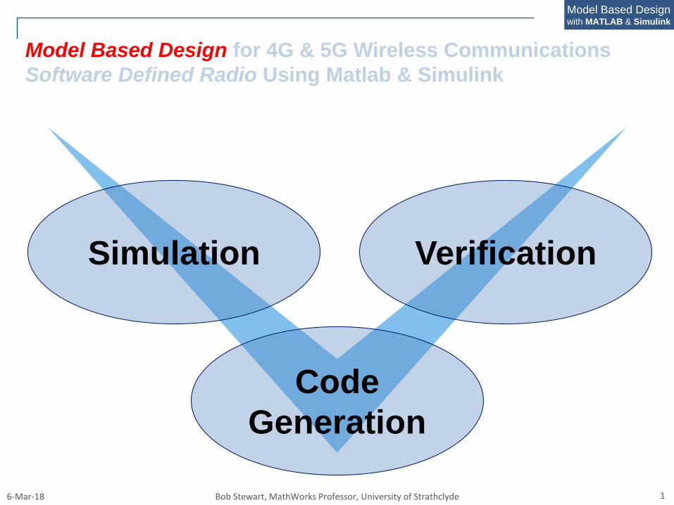
Model Based Design for 4G & 5G Wireless Communications
Software Defined Radio Using Matlab & Simulink
Simulation
Code
Generation
Verification
6-Mar-18 Bob Stewart, MathWorks Professor, University of Strathclyde 2
Model Based Designwith MATLAB & Simulink
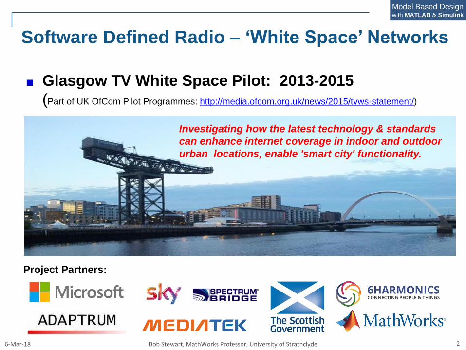
Software Defined Radio – ‘White Space’ Networks
Glasgow TV White Space Pilot: 2013-2015
(Part of UK OfCom Pilot Programmes: http://media.ofcom.org.uk/news/2015/tvws-statement/)
Investigating how the latest technology & standards
can enhance internet coverage in indoor and outdoor
urban locations, enable 'smart city' functionality.
Project Partners:
6-Mar-18 Bob Stewart, MathWorks Professor, University of Strathclyde 5
Model Based Designwith MATLAB & Simulink
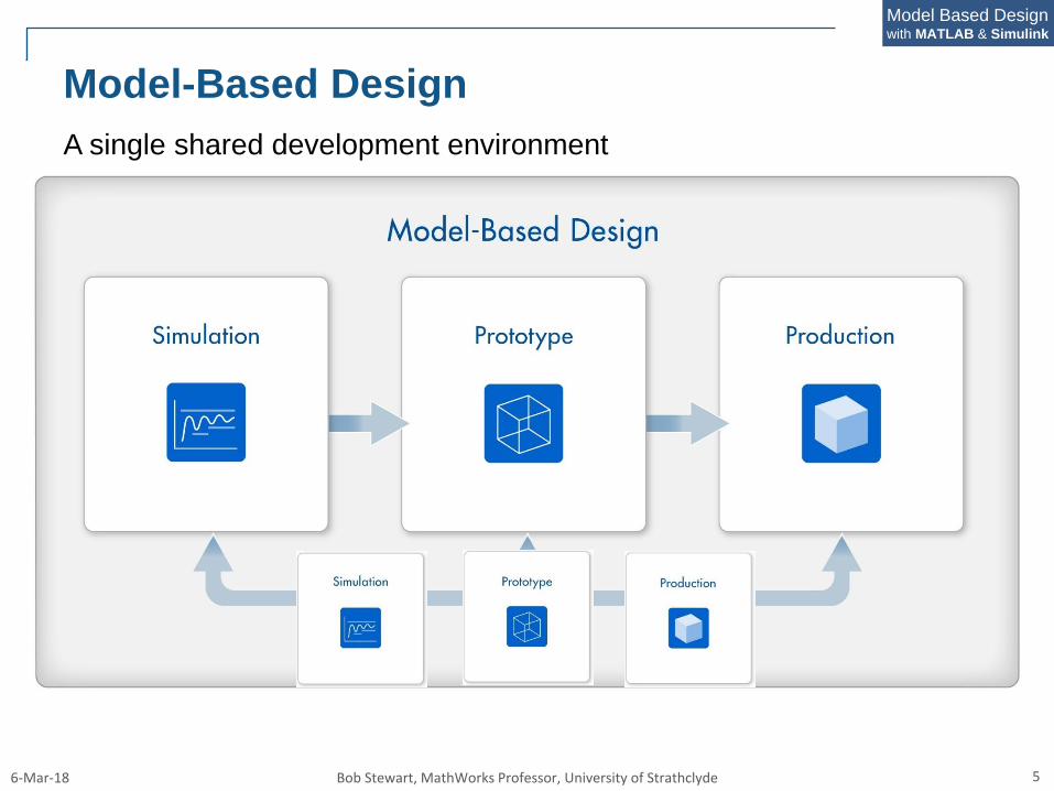
Model-Based Design
A single shared development environment
6-Mar-18 Bob Stewart, MathWorks Professor, University of Strathclyde 6
Model Based Designwith MATLAB & Simulink
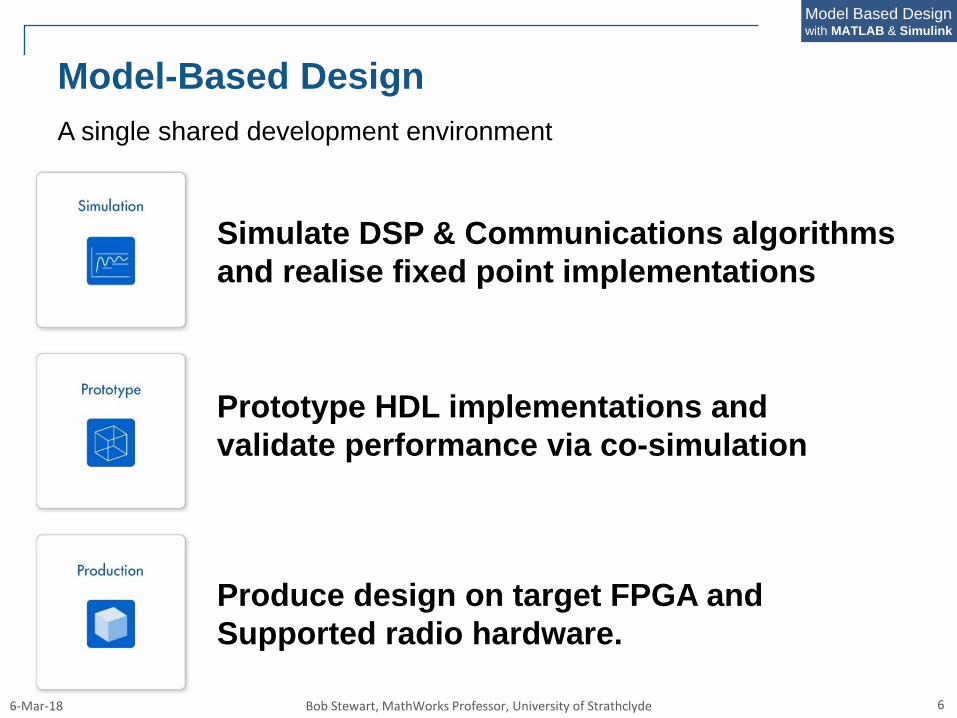
Model-Based Design
Simulate DSP & Communications algorithms
and realise fixed point implementations
Prototype HDL implementations and
validate performance via co-simulation
Produce design on target FPGA and
Supported radio hardware.
A single shared development environment
6-Mar-18 Bob Stewart, MathWorks Professor, University of Strathclyde 7
Model Based Designwith MATLAB & Simulink
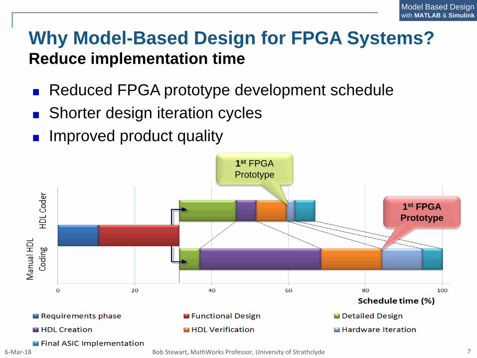
Reduced FPGA prototype development schedule
Shorter design iteration cycles
Improved product quality
Why Model-Based Design for FPGA Systems?Reduce implementation time
1st FPGA
Prototype
1st FPGA
Prototype
6-Mar-18 Bob Stewart, MathWorks Professor, University of Strathclyde 9
Model Based Designwith MATLAB & Simulink
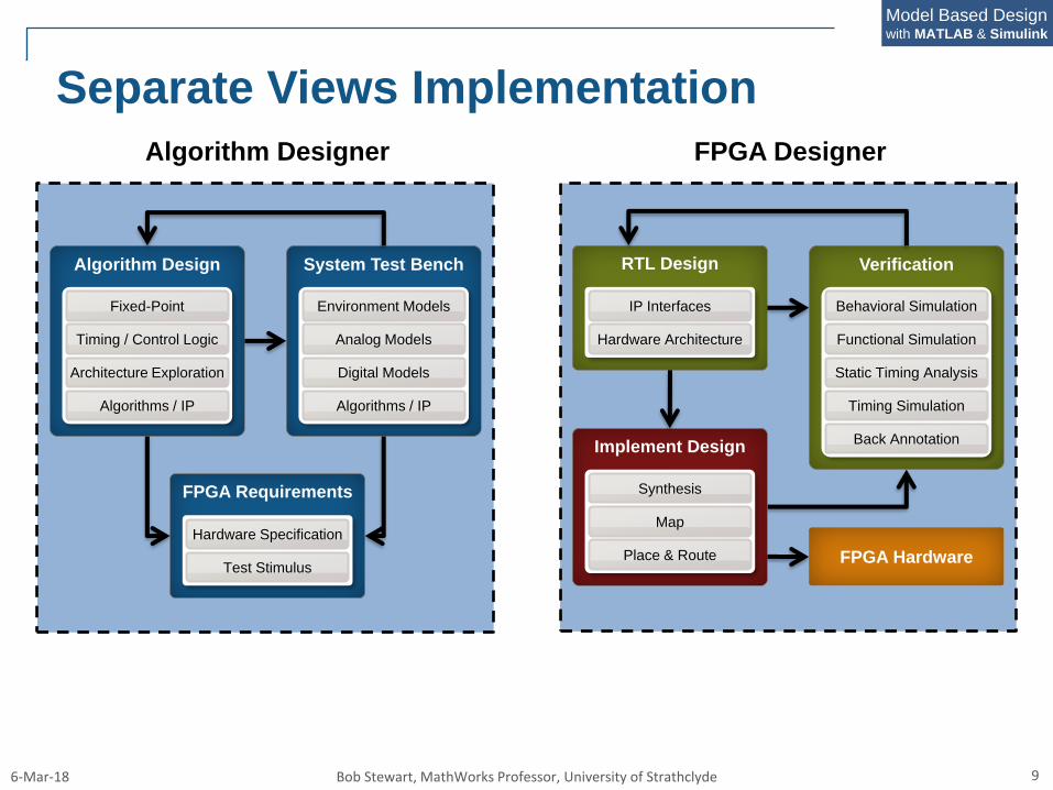
FPGA DesignerAlgorithm Designer
Algorithm Design
Fixed-Point
Timing / Control Logic
Architecture Exploration
Algorithms / IP
System Test Bench
Environment Models
Algorithms / IP
Analog Models
Digital Models
RTL Design
IP Interfaces
Hardware Architecture
Verification
Functional Simulation
Static Timing Analysis
Timing Simulation
Behavioral Simulation
Back AnnotationImplement Design
Map
Place & Route
Synthesis
FPGA Hardware
FPGA Requirements
Hardware Specification
Test Stimulus
Separate Views Implementation
6-Mar-18 Bob Stewart, MathWorks Professor, University of Strathclyde 10
Model Based Designwith MATLAB & Simulink
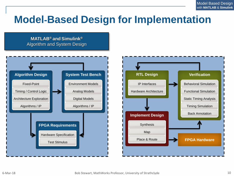
Model-Based Design for Implementation
Algorithm Design
Fixed-Point
Timing / Control Logic
Architecture Exploration
Algorithms / IP
System Test Bench
Environment Models
Algorithms / IP
Analog Models
Digital Models
RTL Design
IP Interfaces
Hardware Architecture
Verification
Functional Simulation
Static Timing Analysis
Timing Simulation
Behavioral Simulation
Back AnnotationImplement Design
Map
Place & Route
Synthesis
FPGA Hardware
FPGA Requirements
Hardware Specification
Test Stimulus
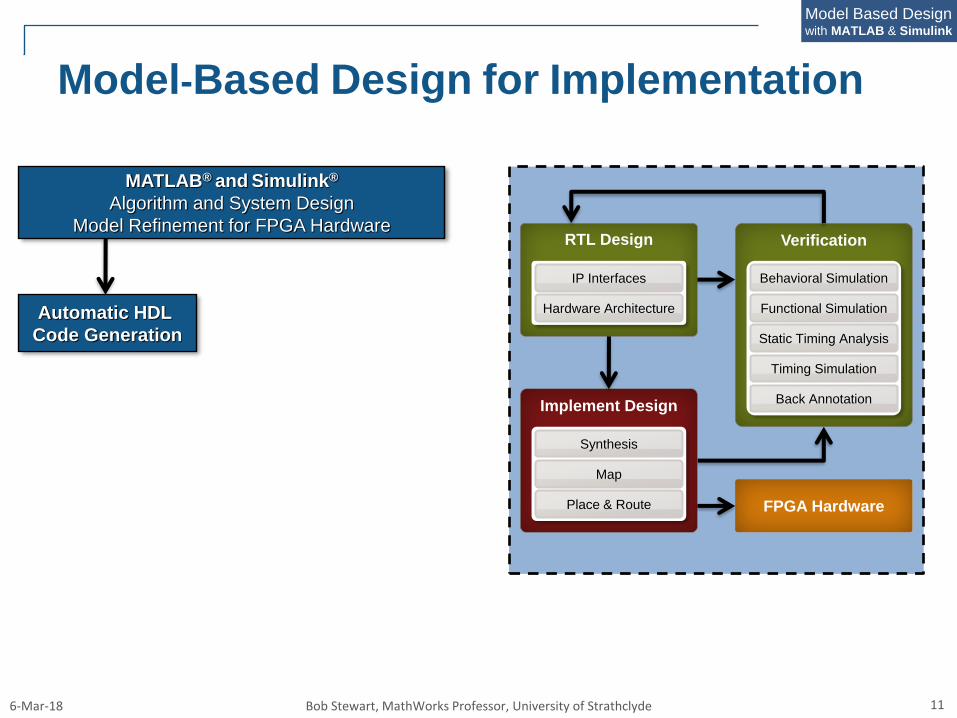
MATLAB® and Simulink®
Algorithm and System Design
6-Mar-18 Bob Stewart, MathWorks Professor, University of Strathclyde 11
Model Based Designwith MATLAB & Simulink
MATLAB® and Simulink®
Algorithm and System Design
Model Refinement for FPGA Hardware
Model-Based Design for Implementation
RTL Design
IP Interfaces
Hardware Architecture
Verification
Functional Simulation
Static Timing Analysis
Timing Simulation
Behavioral Simulation
Back AnnotationImplement Design
Map
Place & Route
Synthesis
FPGA Hardware
Automatic HDL
Code Generation
6-Mar-18 Bob Stewart, MathWorks Professor, University of Strathclyde 12
Model Based Designwith MATLAB & Simulink
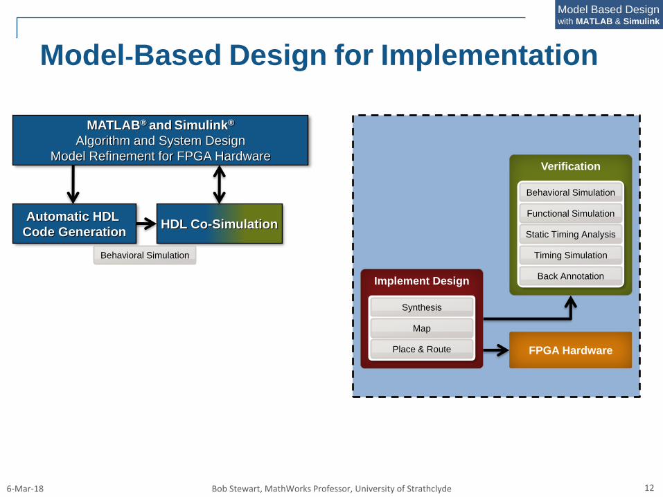
MATLAB® and Simulink®
Algorithm and System Design
Model Refinement for FPGA Hardware
Model-Based Design for Implementation
Verification
Functional Simulation
Static Timing Analysis
Timing Simulation
Behavioral Simulation
Back AnnotationImplement Design
Map
Place & Route
Synthesis
FPGA Hardware
HDL Co-SimulationAutomatic HDL
Code Generation
Behavioral Simulation
6-Mar-18 Bob Stewart, MathWorks Professor, University of Strathclyde 13
Model Based Designwith MATLAB & Simulink
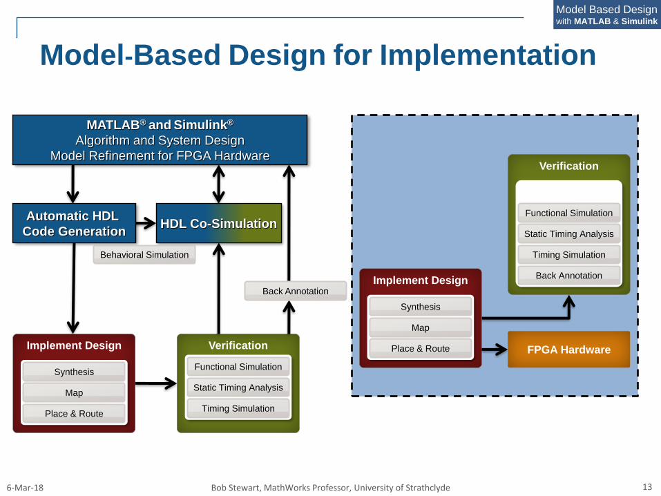
Model-Based Design for Implementation
Verification
Static Timing Analysis
Timing Simulation
Back AnnotationImplement Design
Map
Place & Route
Synthesis
FPGA HardwareImplement Design
Map
Place & Route
Synthesis
Functional Simulation
Verification
Static Timing Analysis
Timing Simulation
Functional Simulation
Back Annotation
HDL Co-SimulationAutomatic HDL
Code Generation
Behavioral Simulation
MATLAB® and Simulink®
Algorithm and System Design
Model Refinement for FPGA Hardware
6-Mar-18 Bob Stewart, MathWorks Professor, University of Strathclyde 14
Model Based Designwith MATLAB & Simulink
FPGA Hardware
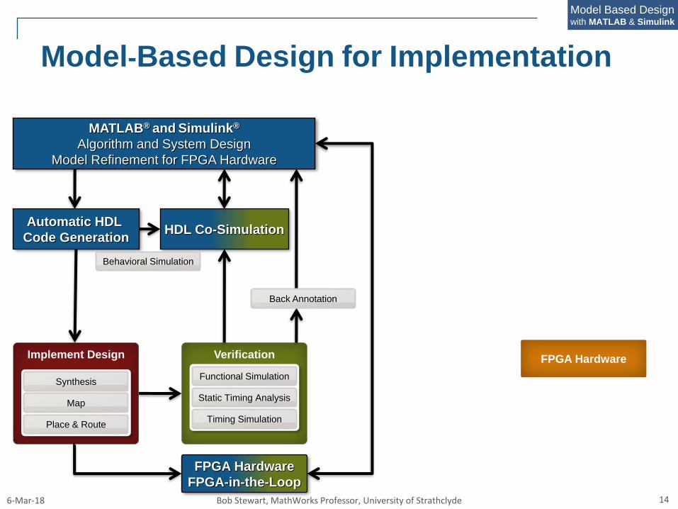
Model-Based Design for Implementation
Implement Design
Map
Place & Route
Synthesis
Verification
Static Timing Analysis
Timing Simulation
Functional Simulation
Back Annotation
HDL Co-SimulationAutomatic HDL
Code Generation
Behavioral Simulation
MATLAB® and Simulink®
Algorithm and System Design
Model Refinement for FPGA Hardware
FPGA Hardware
FPGA-in-the-Loop
6-Mar-18 Bob Stewart, MathWorks Professor, University of Strathclyde 15
Model Based Designwith MATLAB & Simulink
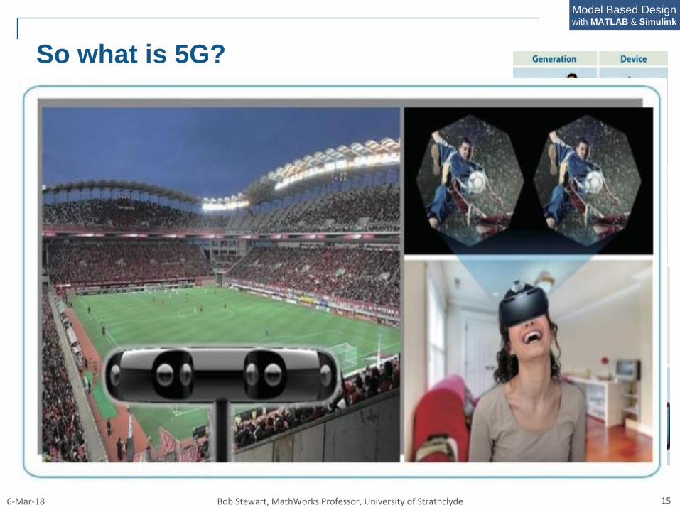
So what is 5G?
6-Mar-18 Bob Stewart, MathWorks Professor, University of Strathclyde 16
Model Based Designwith MATLAB & Simulink
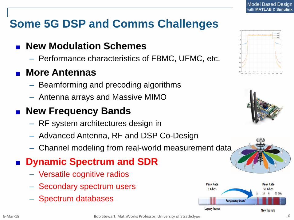
Some 5G DSP and Comms Challenges
New Modulation Schemes
– Performance characteristics of FBMC, UFMC, etc.
More Antennas
– Beamforming and precoding algorithms
– Antenna arrays and Massive MIMO
New Frequency Bands
– RF system architectures design in
– Advanced Antenna, RF and DSP Co-Design
– Channel modeling from real-world measurement data
Dynamic Spectrum and SDR
– Versatile cognitive radios
– Secondary spectrum users
– Spectrum databases
6-Mar-18 Bob Stewart, MathWorks Professor, University of Strathclyde 19
Model Based Designwith MATLAB & Simulink
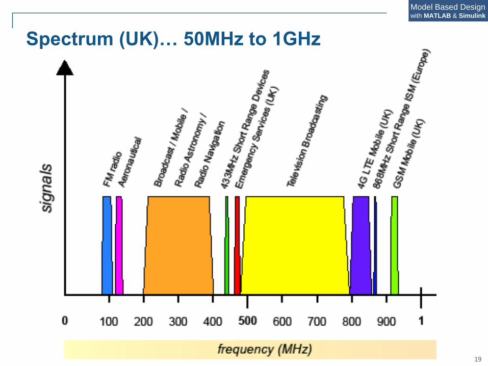
Spectrum (UK)… 50MHz to 1GHz
6-Mar-18 Bob Stewart, MathWorks Professor, University of Strathclyde 20
Model Based Designwith MATLAB & Simulink
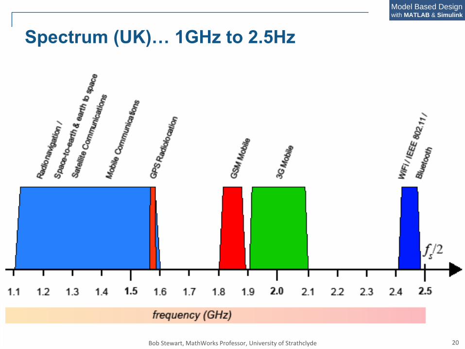
Spectrum (UK)… 1GHz to 2.5Hz

6-Mar-18 Bob Stewart, MathWorks Professor, University of Strathclyde 21
Model Based Designwith MATLAB & Simulink
Software Defined Radio – ‘White Space’ Networks
Glasgow TV White Space Pilot: 2013-2015
(Part of UK OfCom Pilot Programmes: http://media.ofcom.org.uk/news/2015/tvws-statement/)
Investigating how the latest technology & standards
can enhance internet coverage in indoor and outdoor
urban locations, enable 'smart city' functionality.
Project Partners:
6-Mar-18 Bob Stewart, MathWorks Professor, University of Strathclyde 22
Model Based Designwith MATLAB & Simulink
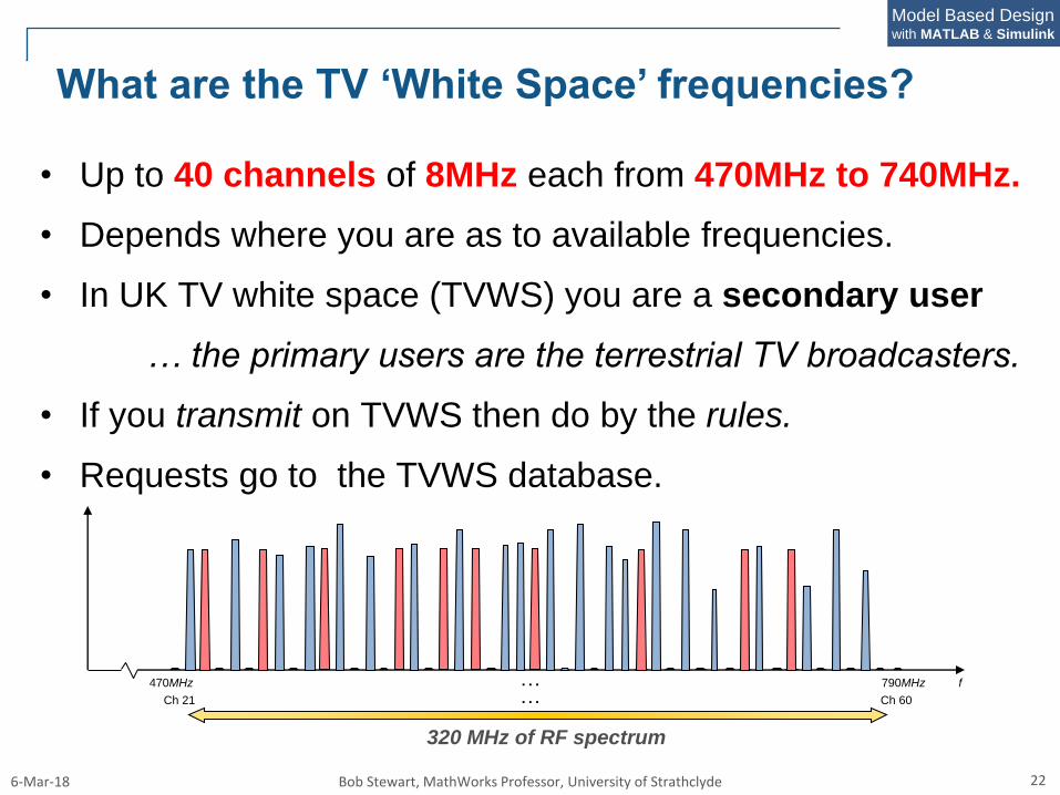
What are the TV ‘White Space’ frequencies?
790MHz470MHz f
Ch 21 Ch 60
……
320 MHz of RF spectrum
• Up to 40 channels of 8MHz each from 470MHz to 740MHz.
• Depends where you are as to available frequencies.
• In UK TV white space (TVWS) you are a secondary user
… the primary users are the terrestrial TV broadcasters.
• If you transmit on TVWS then do by the rules.
• Requests go to the TVWS database.
6-Mar-18 Bob Stewart, MathWorks Professor, University of Strathclyde 23
Model Based Designwith MATLAB & Simulink
TV White Space – Dynamic Spectrum Access
Regulators around the world are recognizing the importance of
TV white space and have been progressing towards the
creation of regulatory frameworks
Licence-exempt
Access controlled by regulator-approved database
US regulator (FCC) was first to legalize licence-exempt access
to TV white spaces in the US, in 2008, and revised in 2010.
UK regulator (Ofcom) has proposed a more ambitious and more
flexible approach, which will increase the efficiency with which
this spectrum can be harnessed – access opened January 2016
Many other regulators are also progressing towards regulation.
6-Mar-18 Bob Stewart, MathWorks Professor, University of Strathclyde 24
Model Based Designwith MATLAB & Simulink
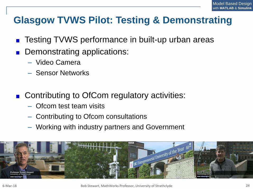
Glasgow TVWS Pilot: Testing & Demonstrating
Testing TVWS performance in built-up urban areas
Demonstrating applications:
– Video Camera
– Sensor Networks
Contributing to OfCom regulatory activities:
– Ofcom test team visits
– Contributing to Ofcom consultations
– Working with industry partners and Government
6-Mar-18 Bob Stewart, MathWorks Professor, University of Strathclyde 25
Model Based Designwith MATLAB & Simulink
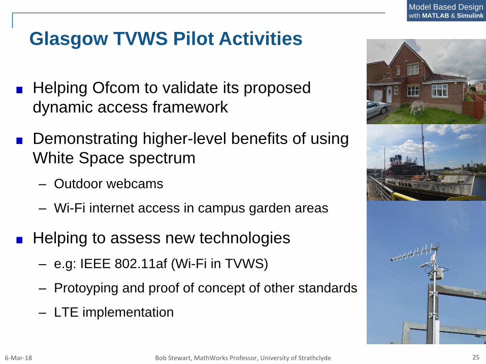
Glasgow TVWS Pilot Activities
Helping Ofcom to validate its proposed
dynamic access framework
Demonstrating higher-level benefits of using
White Space spectrum
– Outdoor webcams
– Wi-Fi internet access in campus garden areas
Helping to assess new technologies
– e.g: IEEE 802.11af (Wi-Fi in TVWS)
– Protoyping and proof of concept of other standards
– LTE implementation
6-Mar-18 Bob Stewart, MathWorks Professor, University of Strathclyde 26
Model Based Designwith MATLAB & Simulink
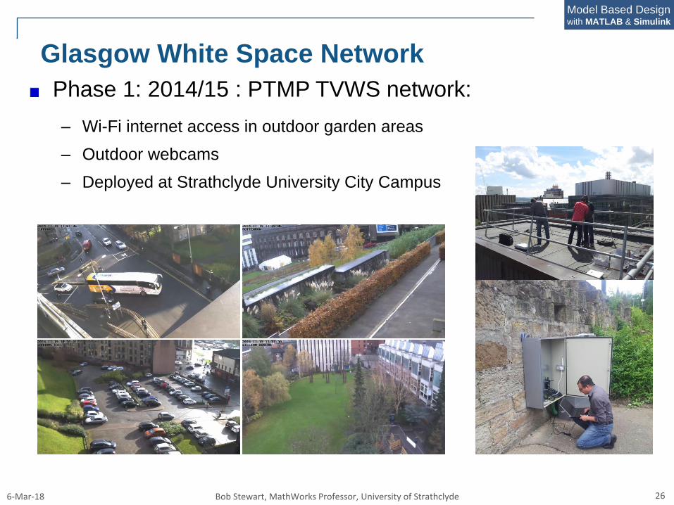
Glasgow White Space Network
Phase 1: 2014/15 : PTMP TVWS network:
– Wi-Fi internet access in outdoor garden areas
– Outdoor webcams
– Deployed at Strathclyde University City Campus
6-Mar-18 Bob Stewart, MathWorks Professor, University of Strathclyde 27
Model Based Designwith MATLAB & Simulink
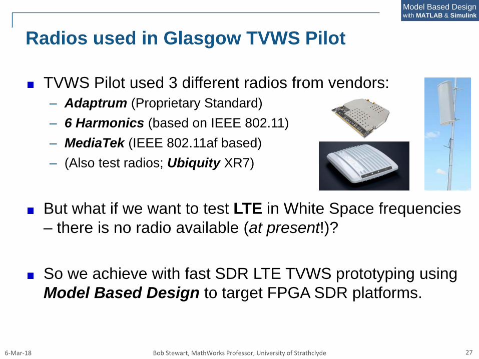
Radios used in Glasgow TVWS Pilot
TVWS Pilot used 3 different radios from vendors:
– Adaptrum (Proprietary Standard)
– 6 Harmonics (based on IEEE 802.11)
– MediaTek (IEEE 802.11af based)
– (Also test radios; Ubiquity XR7)
But what if we want to test LTE in White Space frequencies
– there is no radio available (at present!)?
So we achieve with fast SDR LTE TVWS prototyping using
Model Based Design to target FPGA SDR platforms.
6-Mar-18 Bob Stewart, MathWorks Professor, University of Strathclyde 28
Model Based Designwith MATLAB & Simulink
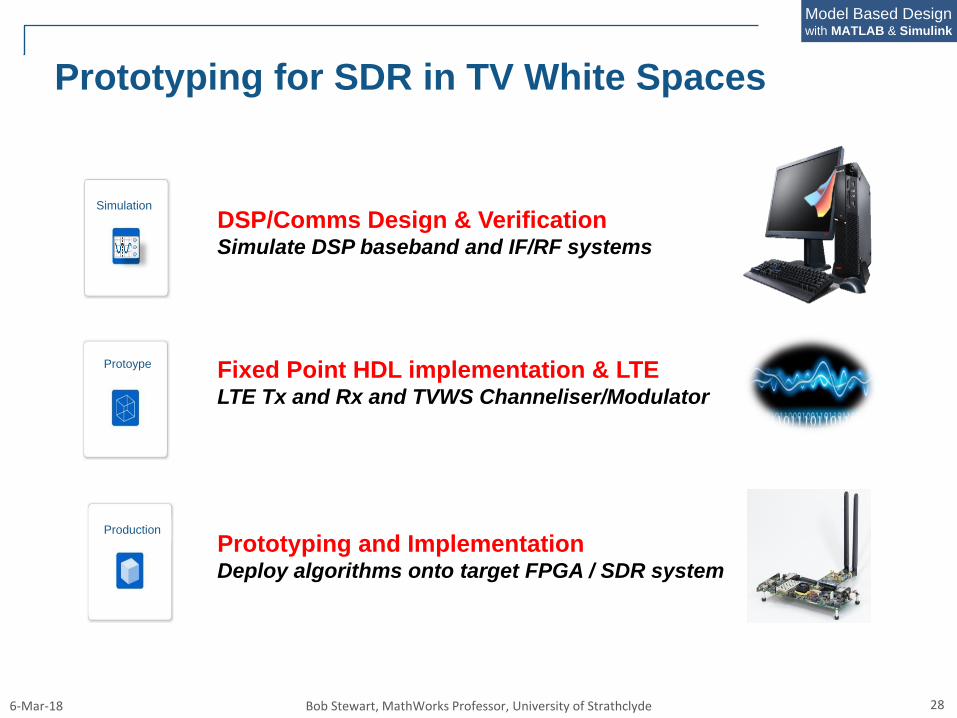
Prototyping for SDR in TV White Spaces
DSP/Comms Design & VerificationSimulate DSP baseband and IF/RF systems
Fixed Point HDL implementation & LTE LTE Tx and Rx and TVWS Channeliser/Modulator
Prototyping and ImplementationDeploy algorithms onto target FPGA / SDR system
Simulation
Protoype
Production

6-Mar-18 Bob Stewart, MathWorks Professor, University of Strathclyde 29
Model Based Designwith MATLAB & Simulink
Model Based Design of SDR for LTE in TVWS
• MathWorks DSP System & Comms Toolbox
• Design 470-740 MHz TVWS Filter Bank
Floating Point Simulation
• MathWorks Fixed Point Designer
• Implement TVWS Filter Bank in Fixed Point
Fixed Point Optimisation
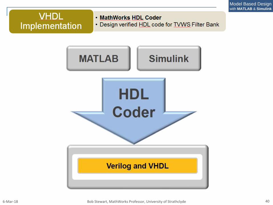
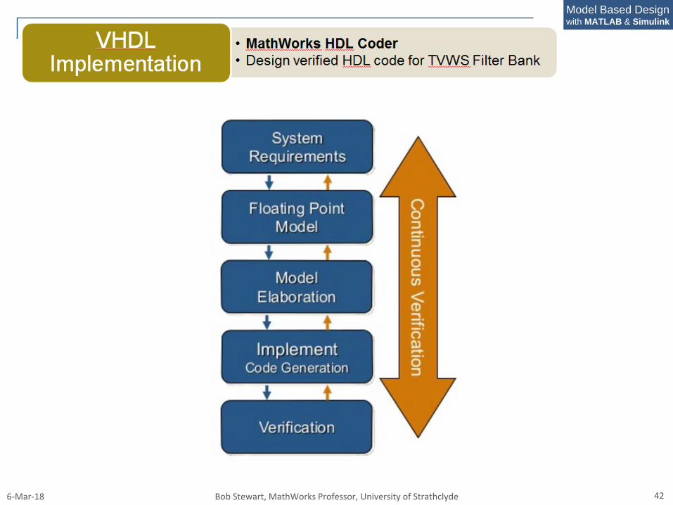
• MathWorks HDL Coder
• Design verified HDL code for TVWS Filter Bank
VHDLImplementation
• MathWorks LTE Systems Toolbox
• Implement LTE Transmit and ReceiveLTE Baseband
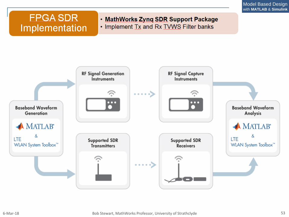
• MathWorks Zynq SDR Support Package
• Implement Tx and Rx TVWS Filter banks
FPGA SDRImplementation
6-Mar-18 Bob Stewart, MathWorks Professor, University of Strathclyde 30
Model Based Designwith MATLAB & Simulink
So what do we need for the TVWS LTE SDR?
Software:
MATLAB & Simulink
DSP Systems Toolbox
Communications System Toolbox
LTE Systems Toolbox
Fixed Point Designer
HDL Coder
Zynq SDR Hardware Support Package
Hardware
Xilinx Zynq FPGA Board & ADI FMComms RF Tx/Rx Card
Radio front ends/amplifier and antennas
6-Mar-18 Bob Stewart, MathWorks Professor, University of Strathclyde 31
Model Based Designwith MATLAB & Simulink
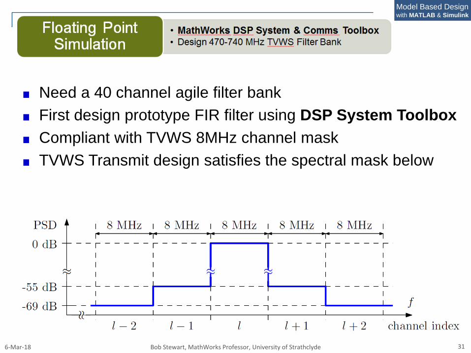
Need a 40 channel agile filter bank
First design prototype FIR filter using DSP System Toolbox
Compliant with TVWS 8MHz channel mask
TVWS Transmit design satisfies the spectral mask below
6-Mar-18 Bob Stewart, MathWorks Professor, University of Strathclyde 32
Model Based Designwith MATLAB & Simulink
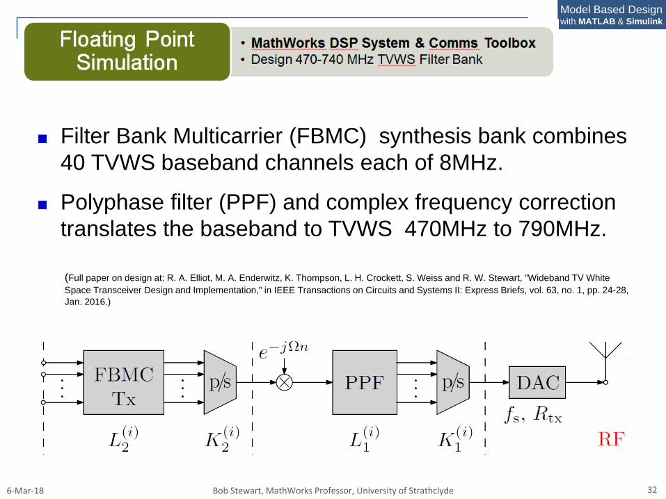
Filter Bank Multicarrier (FBMC) synthesis bank combines
40 TVWS baseband channels each of 8MHz.
Polyphase filter (PPF) and complex frequency correction
translates the baseband to TVWS 470MHz to 790MHz.
(Full paper on design at: R. A. Elliot, M. A. Enderwitz, K. Thompson, L. H. Crockett, S. Weiss and R. W. Stewart, "Wideband TV White
Space Transceiver Design and Implementation," in IEEE Transactions on Circuits and Systems II: Express Briefs, vol. 63, no. 1, pp. 24-28,
Jan. 2016.)
6-Mar-18 Bob Stewart, MathWorks Professor, University of Strathclyde 33
Model Based Designwith MATLAB & Simulink
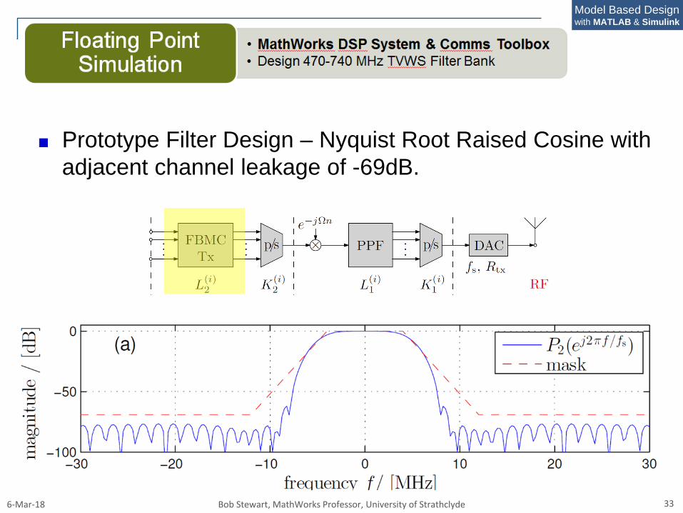
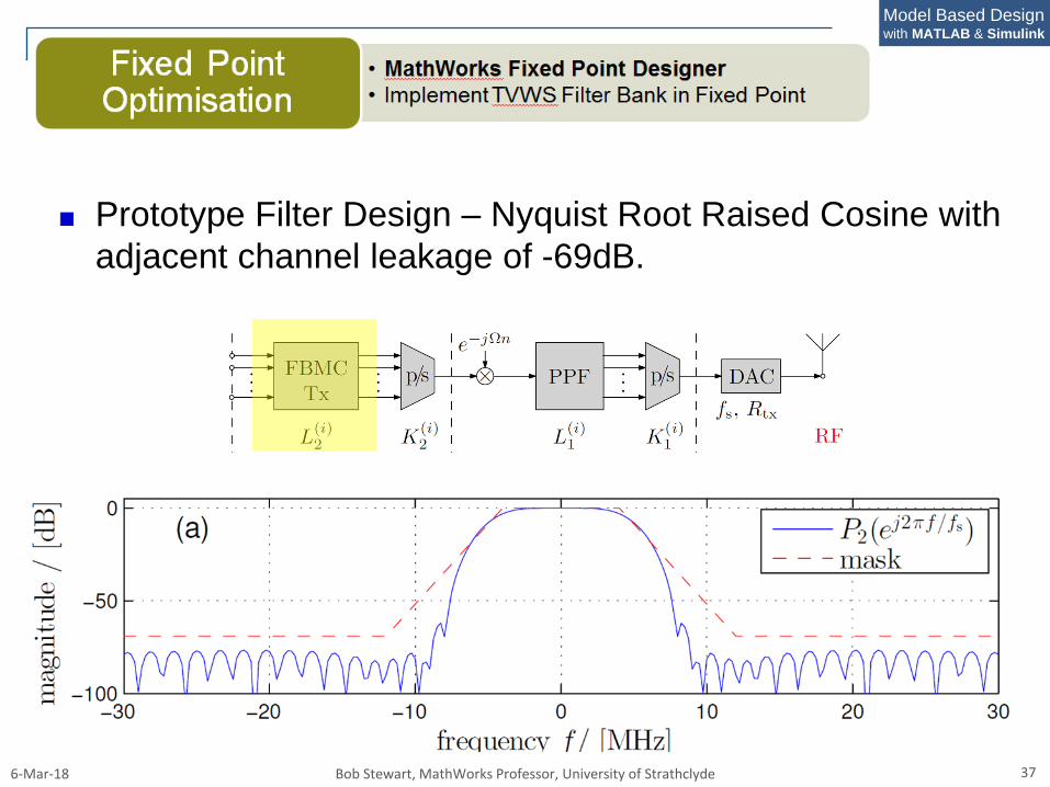
Prototype Filter Design – Nyquist Root Raised Cosine with
adjacent channel leakage of -69dB.
6-Mar-18 Bob Stewart, MathWorks Professor, University of Strathclyde 34
Model Based Designwith MATLAB & Simulink
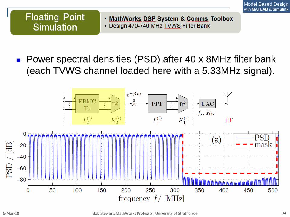
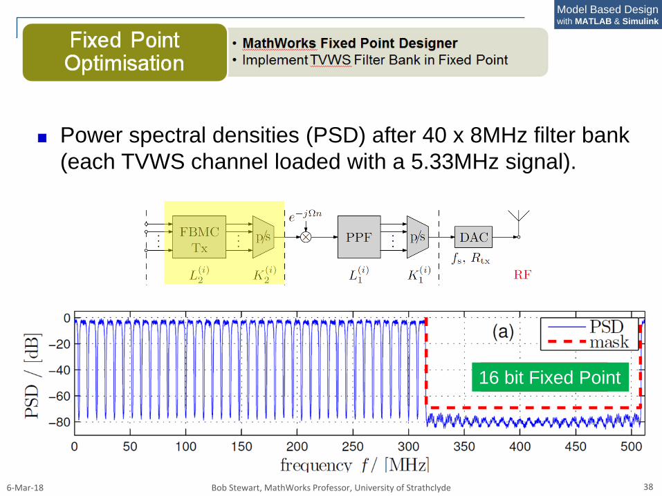
Power spectral densities (PSD) after 40 x 8MHz filter bank
(each TVWS channel loaded here with a 5.33MHz signal).
6-Mar-18 Bob Stewart, MathWorks Professor, University of Strathclyde 35
Model Based Designwith MATLAB & Simulink
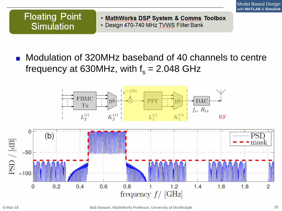
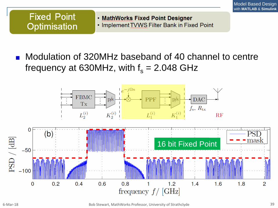
Modulation of 320MHz baseband of 40 channels to centre
frequency at 630MHz, with fs = 2.048 GHz
6-Mar-18 Bob Stewart, MathWorks Professor, University of Strathclyde 36
Model Based Designwith MATLAB & Simulink
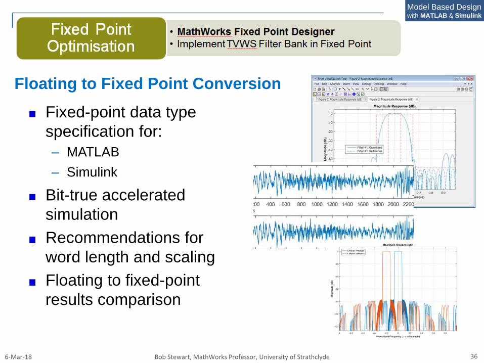
Fixed-point data type
specification for:
– MATLAB
– Simulink
Bit-true accelerated
simulation
Recommendations for
word length and scaling
Floating to fixed-point
results comparison
Floating to Fixed Point Conversion
6-Mar-18 Bob Stewart, MathWorks Professor, University of Strathclyde 37
Model Based Designwith MATLAB & Simulink
Prototype Filter Design – Nyquist Root Raised Cosine with
adjacent channel leakage of -69dB.
6-Mar-18 Bob Stewart, MathWorks Professor, University of Strathclyde 38
Model Based Designwith MATLAB & Simulink
Power spectral densities (PSD) after 40 x 8MHz filter bank
(each TVWS channel loaded with a 5.33MHz signal).
Floating Point16 bit Fixed Point
6-Mar-18 Bob Stewart, MathWorks Professor, University of Strathclyde 39
Model Based Designwith MATLAB & Simulink
Modulation of 320MHz baseband of 40 channel to centre
frequency at 630MHz, with fs = 2.048 GHz
Floating Point16 bit Fixed Point
6-Mar-18 Bob Stewart, MathWorks Professor, University of Strathclyde 40
Model Based Designwith MATLAB & Simulink
6-Mar-18 Bob Stewart, MathWorks Professor, University of Strathclyde 41
Model Based Designwith MATLAB & Simulink
HDL Coder generates portable, synthesizable VHDL and
Verilog code from MATLAB functions, Simulink models.
The generated HDL code can be used for FPGA
programming or ASIC prototyping and design.
Provides a workflow advisor for working with Xilinx and
Altera software tools and design flows.
Controls architecture and implementation and highlight
critical timing paths limiting clocking frequencies.
Generate hardware resource utilization estimates for
designs to target FPGA hardware.
Provides traceability between Simulink model and the
generated Verilog and VHDL code.
6-Mar-18 Bob Stewart, MathWorks Professor, University of Strathclyde 42
Model Based Designwith MATLAB & Simulink
6-Mar-18 Bob Stewart, MathWorks Professor, University of Strathclyde 43
Model Based Designwith MATLAB & Simulink
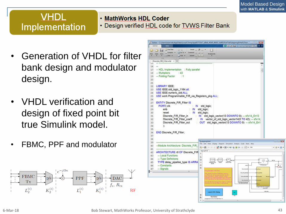
• Generation of VHDL for filter
bank design and modulator
design.
• VHDL verification and
design of fixed point bit
true Simulink model.
• FBMC, PPF and modulator
6-Mar-18 Bob Stewart, MathWorks Professor, University of Strathclyde 44
Model Based Designwith MATLAB & Simulink
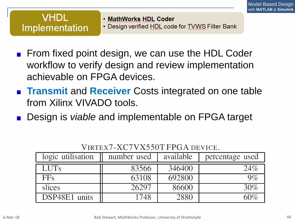
From fixed point design, we can use the HDL Coder
workflow to verify design and review implementation
achievable on FPGA devices.
Transmit and Receiver Costs integrated on one table
from Xilinx VIVADO tools.
Design is viable and implementable on FPGA target
6-Mar-18 Bob Stewart, MathWorks Professor, University of Strathclyde 45
Model Based Designwith MATLAB & Simulink
LTE Systems Toolbox
Simulates the physical layer of LTE and LTE-Advanced
wireless communications systems.
Standard-compliant functions and apps for the design,
simulation, and verification of LTE and LTE-Advanced.
Accelerates LTE algorithm and physical layer (PHY)
development, supporting golden reference verification.
Conformance testing, and also enabling test waveform
generation, suitable for our TVWS links.
Can configure, simulate, measure, and analyze end-to-
end communications links.
6-Mar-18 Bob Stewart, MathWorks Professor, University of Strathclyde 46
Model Based Designwith MATLAB & Simulink
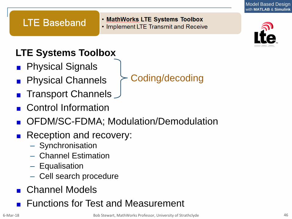
LTE Systems Toolbox
Physical Signals
Physical Channels
Transport Channels
Control Information
OFDM/SC-FDMA; Modulation/Demodulation
Reception and recovery:– Synchronisation
– Channel Estimation
– Equalisation
– Cell search procedure
Channel Models
Functions for Test and Measurement
Coding/decoding
6-Mar-18 Bob Stewart, MathWorks Professor, University of Strathclyde 47
Model Based Designwith MATLAB & Simulink
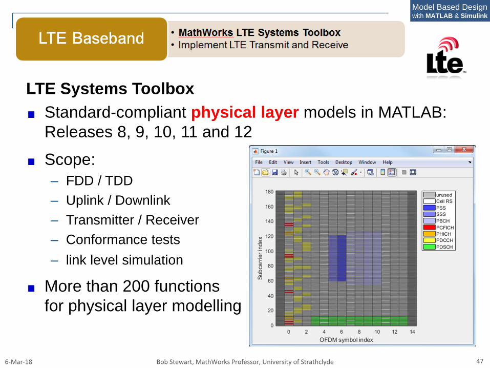
LTE Systems Toolbox
Standard-compliant physical layer models in MATLAB:
Releases 8, 9, 10, 11 and 12
Scope:
– FDD / TDD
– Uplink / Downlink
– Transmitter / Receiver
– Conformance tests
– link level simulation
More than 200 functions
for physical layer modelling
6-Mar-18 Bob Stewart, MathWorks Professor, University of Strathclyde 48
Model Based Designwith MATLAB & Simulink
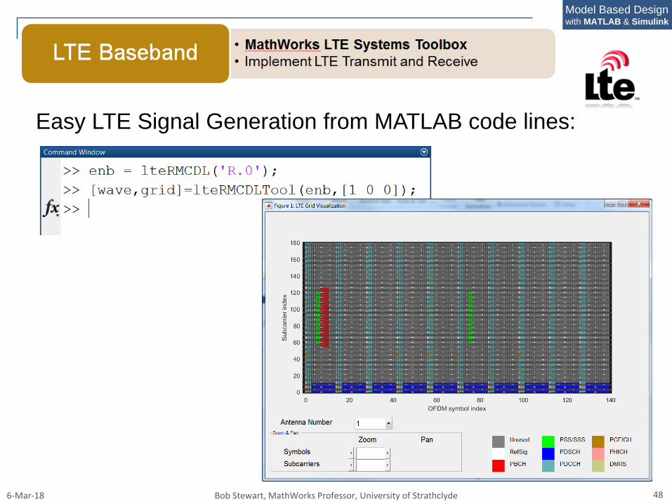
Easy LTE Signal Generation from MATLAB code lines:
6-Mar-18 Bob Stewart, MathWorks Professor, University of Strathclyde 49
Model Based Designwith MATLAB & Simulink
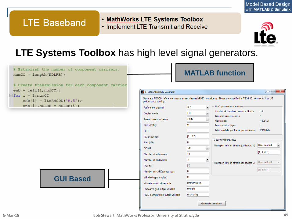
LTE Systems Toolbox has high level signal generators.
GUI Based
MATLAB function
6-Mar-18 Bob Stewart, MathWorks Professor, University of Strathclyde 50
Model Based Designwith MATLAB & Simulink
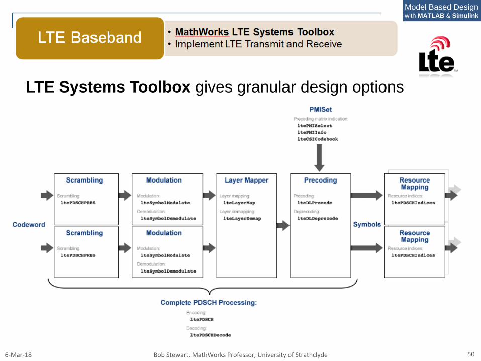
LTE Systems Toolbox gives granular design options
6-Mar-18 Bob Stewart, MathWorks Professor, University of Strathclyde 51
Model Based Designwith MATLAB & Simulink
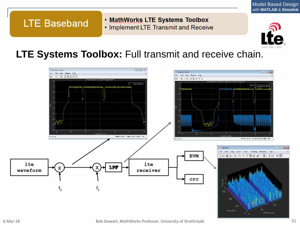
LTE Systems Toolbox: Full transmit and receive chain.
lte
receiver
EVM
crc
lte
waveform x
f2
x
f1
6-Mar-18 Bob Stewart, MathWorks Professor, University of Strathclyde 52
Model Based Designwith MATLAB & Simulink
LTE System Toolbox: using TDD for TVWS:
– Bandwidth: 5 MHz
– Modulation:
BPSK / QPSK / 16QAM / 64QAM
BPSK : Control
– 64QAM: data channel
– Duplex method: TDD / FDD
6-Mar-18 Bob Stewart, MathWorks Professor, University of Strathclyde 53
Model Based Designwith MATLAB & Simulink
LTE LTE
6-Mar-18 Bob Stewart, MathWorks Professor, University of Strathclyde 54
Model Based Designwith MATLAB & Simulink
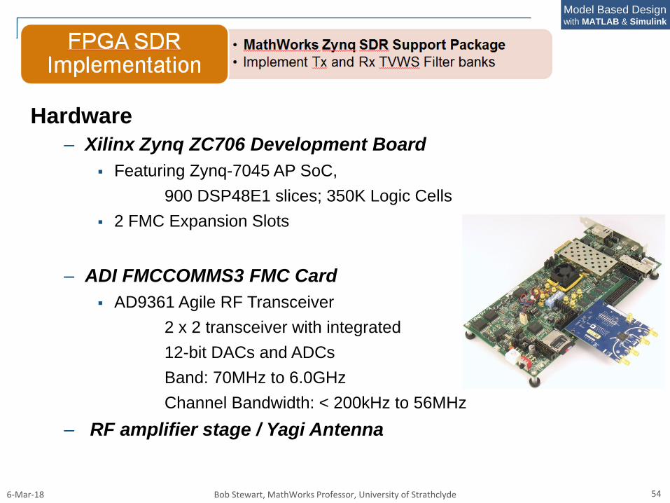
Hardware
– Xilinx Zynq ZC706 Development Board
Featuring Zynq-7045 AP SoC,
900 DSP48E1 slices; 350K Logic Cells
2 FMC Expansion Slots
– ADI FMCCOMMS3 FMC Card
AD9361 Agile RF Transceiver
2 x 2 transceiver with integrated
12-bit DACs and ADCs
Band: 70MHz to 6.0GHz
Channel Bandwidth: < 200kHz to 56MHz
– RF amplifier stage / Yagi Antenna
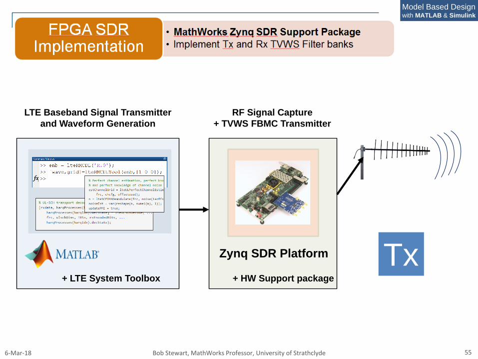
6-Mar-18 Bob Stewart, MathWorks Professor, University of Strathclyde 55
Model Based Designwith MATLAB & Simulink
LTE Baseband Signal Transmitter
and Waveform Generation
RF Signal Capture
+ TVWS FBMC Transmitter
+ LTE System Toolbox + HW Support package
Zynq SDR Platform Tx
6-Mar-18 Bob Stewart, MathWorks Professor, University of Strathclyde 56
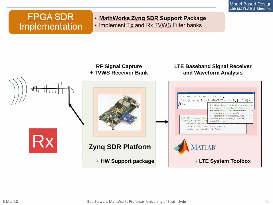
Model Based Designwith MATLAB & Simulink
LTE Baseband Signal Receiver
and Waveform Analysis
RF Signal Capture
+ TVWS Receiver Bank
+ LTE System Toolbox+ HW Support package
Zynq SDR PlatformRx
6-Mar-18 Bob Stewart, MathWorks Professor, University of Strathclyde 57
Model Based Designwith MATLAB & Simulink
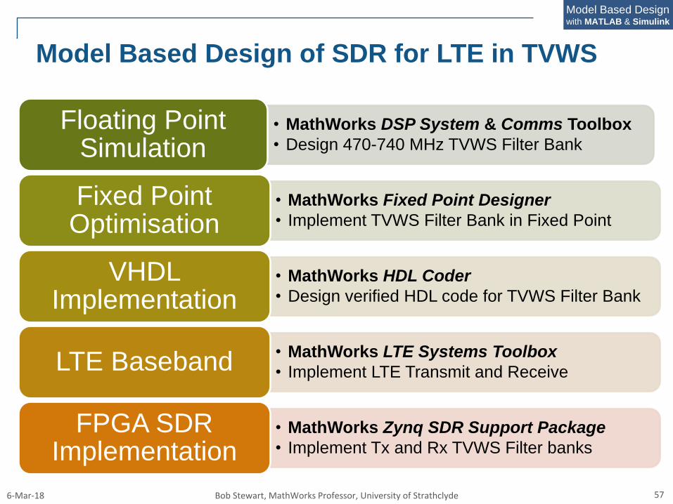
Model Based Design of SDR for LTE in TVWS
• MathWorks DSP System & Comms Toolbox
• Design 470-740 MHz TVWS Filter Bank
Floating Point Simulation
• MathWorks Fixed Point Designer
• Implement TVWS Filter Bank in Fixed Point
Fixed Point Optimisation
• MathWorks HDL Coder
• Design verified HDL code for TVWS Filter Bank
VHDLImplementation
• MathWorks LTE Systems Toolbox
• Implement LTE Transmit and ReceiveLTE Baseband
• MathWorks Zynq SDR Support Package
• Implement Tx and Rx TVWS Filter banks
FPGA SDRImplementation
6-Mar-18 Bob Stewart, MathWorks Professor, University of Strathclyde 58
Model Based Designwith MATLAB & Simulink
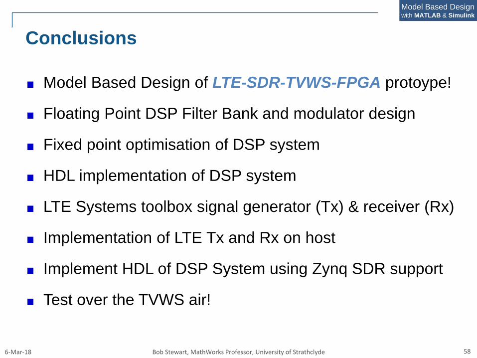
Conclusions
Model Based Design of LTE-SDR-TVWS-FPGA protoype!
Floating Point DSP Filter Bank and modulator design
Fixed point optimisation of DSP system
HDL implementation of DSP system
LTE Systems toolbox signal generator (Tx) & receiver (Rx)
Implementation of LTE Tx and Rx on host
Implement HDL of DSP System using Zynq SDR support
Test over the TVWS air!
6-Mar-18 Bob Stewart, MathWorks Professor, University of Strathclyde 59
Model Based Designwith MATLAB & Simulink
Acknowledgements
Iain Chalmers, Sarunas Kalade,
David Crawford, David
Northcote, Dani Anderson,
Stephan Weiss
at University of Strathclyde
Daniel Garcia-Alis, Neil
MacEwen, Ken Karnoksky
at MathWorks
6-Mar-18 Bob Stewart, MathWorks Professor, University of Strathclyde 60
Model Based Designwith MATLAB & Simulink
Additional Reserve Slides
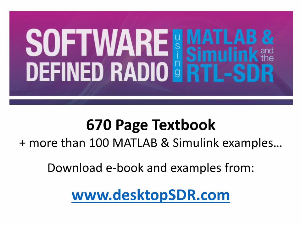
670 Page Textbook+ more than 100 MATLAB & Simulink examples…
Download e-book and examples from:
www.desktopSDR.com
6-Mar-18 Bob Stewart, MathWorks Professor, University of Strathclyde 62
Model Based Designwith MATLAB & Simulink
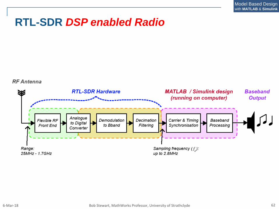
RTL-SDR DSP enabled Radio
6-Mar-18 Bob Stewart, MathWorks Professor, University of Strathclyde 63
Model Based Designwith MATLAB & Simulink
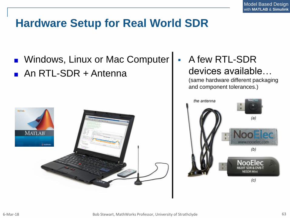
Hardware Setup for Real World SDR
Windows, Linux or Mac Computer
An RTL-SDR + Antenna
A few RTL-SDR
devices available…(same hardware different packaging
and component tolerances.)
6-Mar-18 Bob Stewart, MathWorks Professor, University of Strathclyde 64
Model Based Designwith MATLAB & Simulink
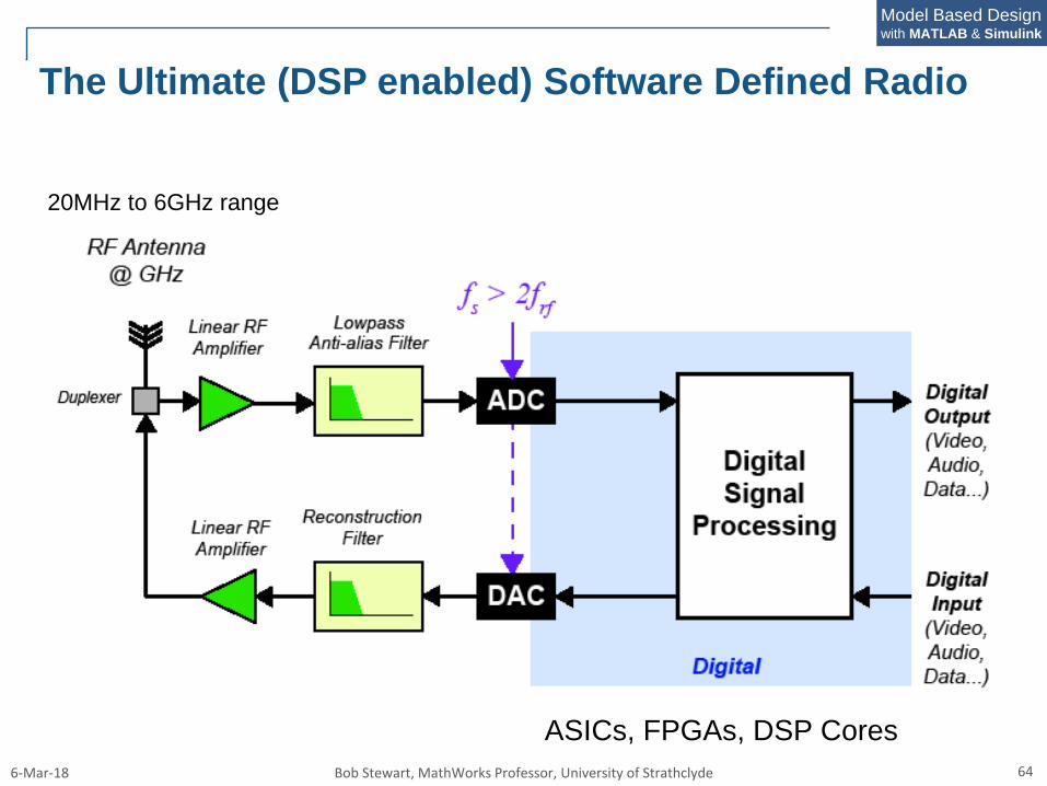
The Ultimate (DSP enabled) Software Defined Radio
20MHz to 6GHz range
ASICs, FPGAs, DSP Cores
6-Mar-18 Bob Stewart, MathWorks Professor, University of Strathclyde 65
Model Based Designwith MATLAB & Simulink
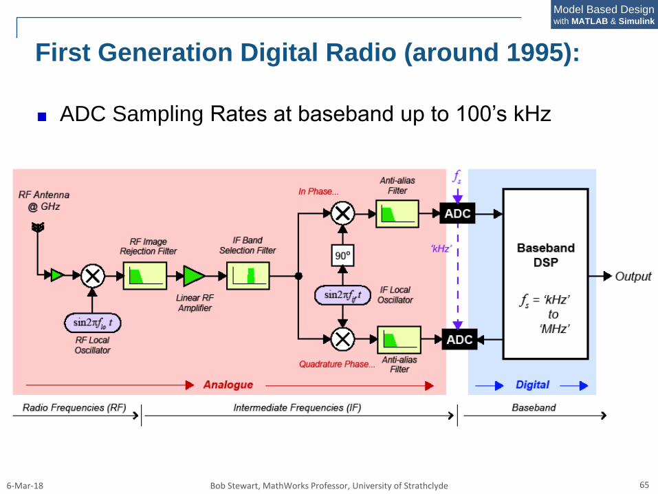
First Generation Digital Radio (around 1995):
ADC Sampling Rates at baseband up to 100’s kHz
6-Mar-18 Bob Stewart, MathWorks Professor, University of Strathclyde 66
Model Based Designwith MATLAB & Simulink
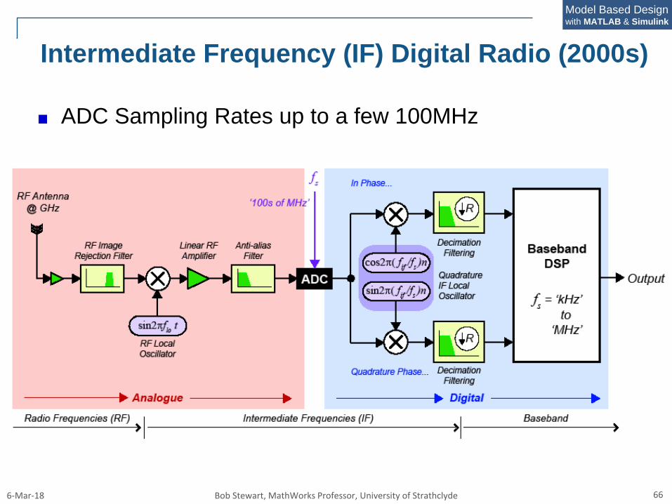
Intermediate Frequency (IF) Digital Radio (2000s)
ADC Sampling Rates up to a few 100MHz
6-Mar-18 Bob Stewart, MathWorks Professor, University of Strathclyde 67
Model Based Designwith MATLAB & Simulink
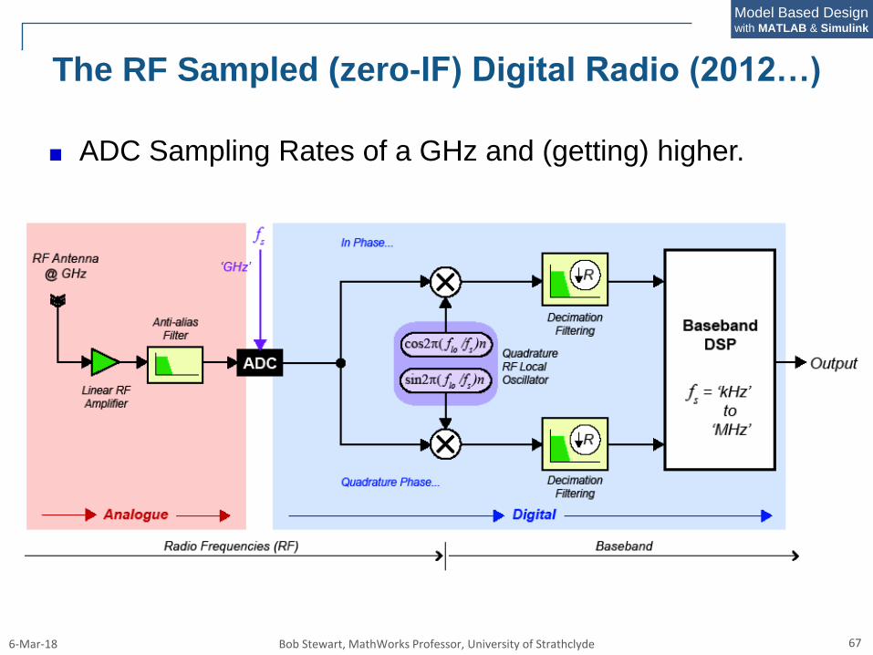
The RF Sampled (zero-IF) Digital Radio (2012…)
ADC Sampling Rates of a GHz and (getting) higher.
6-Mar-18 Bob Stewart, MathWorks Professor, University of Strathclyde 68
Model Based Designwith MATLAB & Simulink
RF
Ante
nna
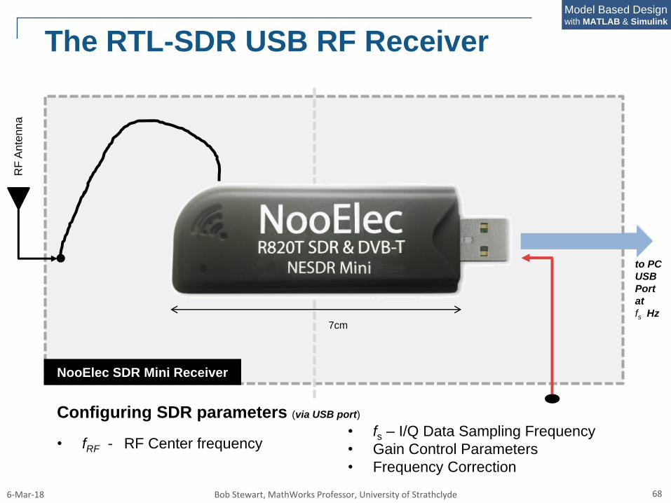
NooElec SDR Mini Receiver
• fs – I/Q Data Sampling Frequency
• Gain Control Parameters
• Frequency Correction
The RTL-SDR USB RF Receiver
Configuring SDR parameters (via USB port)
• fRF - RF Center frequency
7cm
to PC
USB
Port
at
fs Hz
6-Mar-18 Bob Stewart, MathWorks Professor, University of Strathclyde 69
Model Based Designwith MATLAB & Simulink
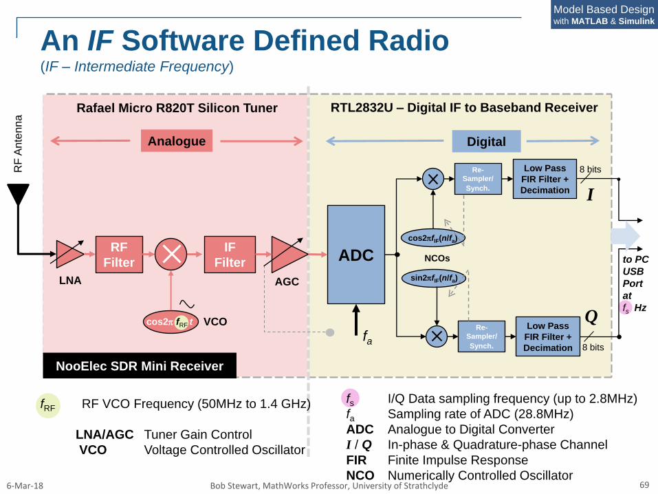
fRF RF VCO Frequency (50MHz to 1.4 GHz)
LNA/AGC Tuner Gain Control
VCO Voltage Controlled Oscillator
Analogue
Rafael Micro R820T Silicon Tuner
Digital
RTL2832U – Digital IF to Baseband Receiver
RF
Ante
nna
fs I/Q Data sampling frequency (up to 2.8MHz)
fa Sampling rate of ADC (28.8MHz)
ADC Analogue to Digital Converter
I / Q In-phase & Quadrature-phase Channel
FIR Finite Impulse Response
NCO Numerically Controlled Oscillator
NooElec SDR Mini Receiver
ADC
cos2pfIF(n/fa)
Low Pass
FIR Filter +
Decimation
fa
Re-
Sampler/
Synch.
sin2pfIF(n/fa)
Low Pass
FIR Filter +
Decimation
Re-
Sampler/
Synch.
8 bits
8 bits
I
NCOs
Q
An IF Software Defined Radio(IF – Intermediate Frequency)
to PC
USB
Port
at
fs Hz
RF
Filter
IF
Filter
LNA AGC
VCOcos2p fRF t
6-Mar-18 Bob Stewart, MathWorks Professor, University of Strathclyde 70
Model Based Designwith MATLAB & Simulink
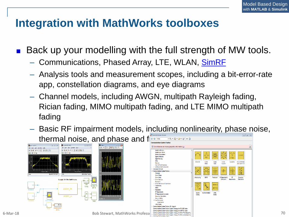
Integration with MathWorks toolboxes
Back up your modelling with the full strength of MW tools.
– Communications, Phased Array, LTE, WLAN, SimRF
– Analysis tools and measurement scopes, including a bit-error-rate
app, constellation diagrams, and eye diagrams
– Channel models, including AWGN, multipath Rayleigh fading,
Rician fading, MIMO multipath fading, and LTE MIMO multipath
fading
– Basic RF impairment models, including nonlinearity, phase noise,
thermal noise, and phase and frequency offsets
6-Mar-18 Bob Stewart, MathWorks Professor, University of Strathclyde 71
Model Based Designwith MATLAB & Simulink
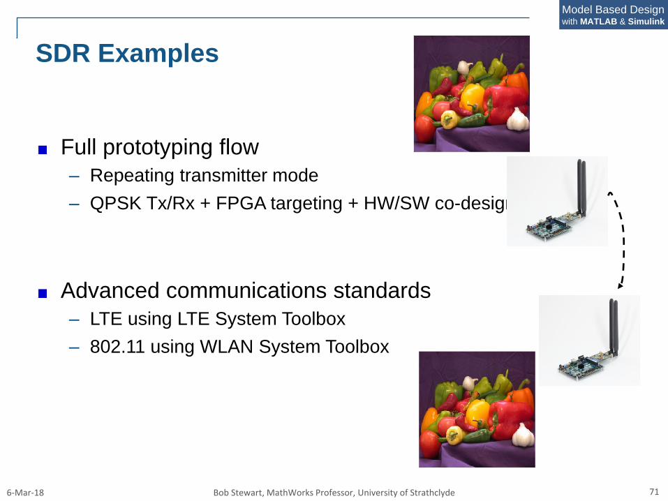
SDR Examples
Full prototyping flow
– Repeating transmitter mode
– QPSK Tx/Rx + FPGA targeting + HW/SW co-design
Advanced communications standards
– LTE using LTE System Toolbox
– 802.11 using WLAN System Toolbox
6-Mar-18 Bob Stewart, MathWorks Professor, University of Strathclyde 72
Model Based Designwith MATLAB & Simulink
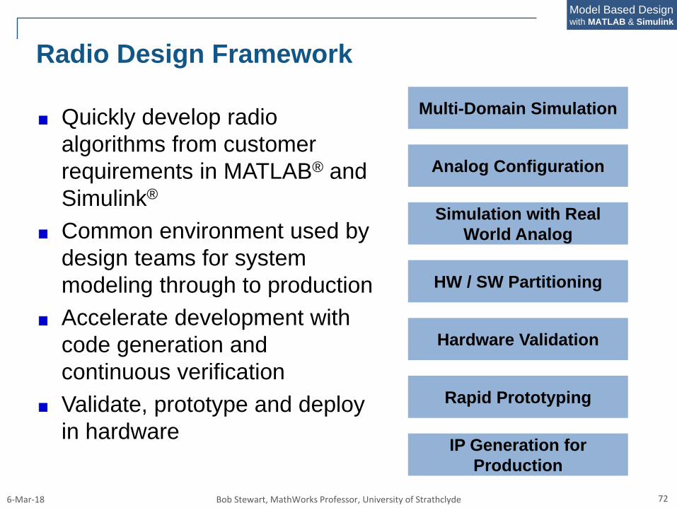
Radio Design Framework
Quickly develop radio
algorithms from customer
requirements in MATLAB® and
Simulink®
Common environment used by
design teams for system
modeling through to production
Accelerate development with
code generation and
continuous verification
Validate, prototype and deploy
in hardware
Multi-Domain Simulation
Analog Configuration
Simulation with Real
World Analog
HW / SW Partitioning
Hardware Validation
Rapid Prototyping
IP Generation for
Production
6-Mar-18 Bob Stewart, MathWorks Professor, University of Strathclyde 73
Model Based Designwith MATLAB & Simulink
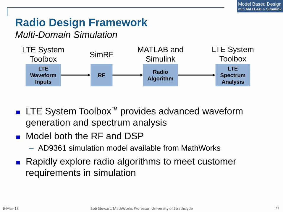
Radio Design FrameworkMulti-Domain Simulation
LTE System Toolbox™ provides advanced waveform
generation and spectrum analysis
Model both the RF and DSP
– AD9361 simulation model available from MathWorks
Rapidly explore radio algorithms to meet customer
requirements in simulation
LTE
Waveform
Inputs
RFRadio
Algorithm
LTE
Spectrum
Analysis
LTE System
Toolbox
LTE System
ToolboxSimRF
MATLAB and
Simulink
6-Mar-18 Bob Stewart, MathWorks Professor, University of Strathclyde 74
Model Based Designwith MATLAB & Simulink
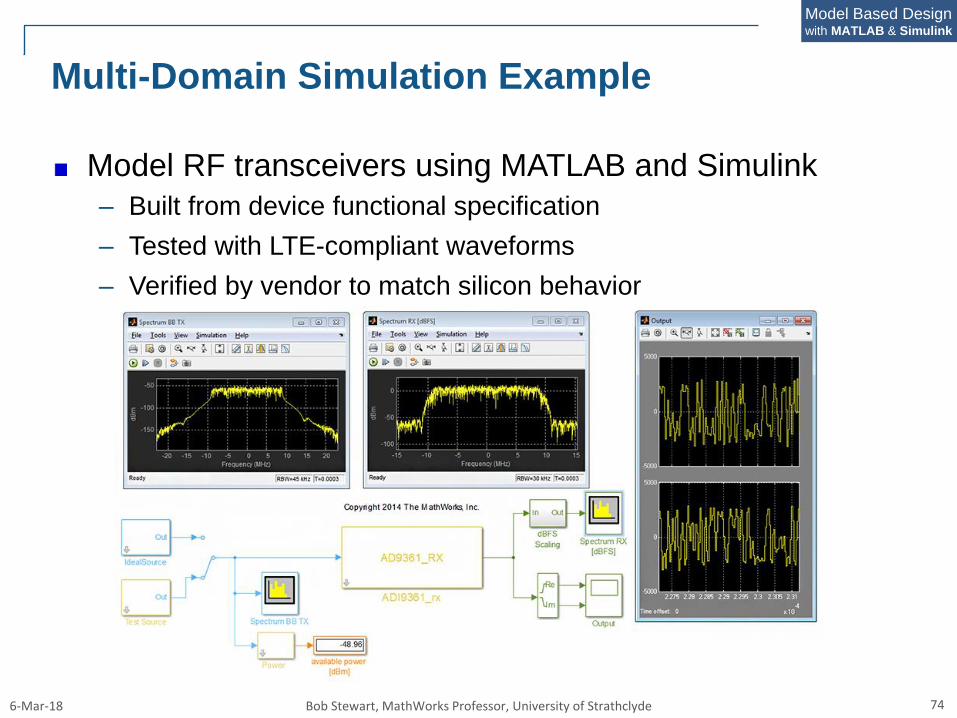
Multi-Domain Simulation Example
Model RF transceivers using MATLAB and Simulink
– Built from device functional specification
– Tested with LTE-compliant waveforms
– Verified by vendor to match silicon behavior
6-Mar-18 Bob Stewart, MathWorks Professor, University of Strathclyde 75
Model Based Designwith MATLAB & Simulink
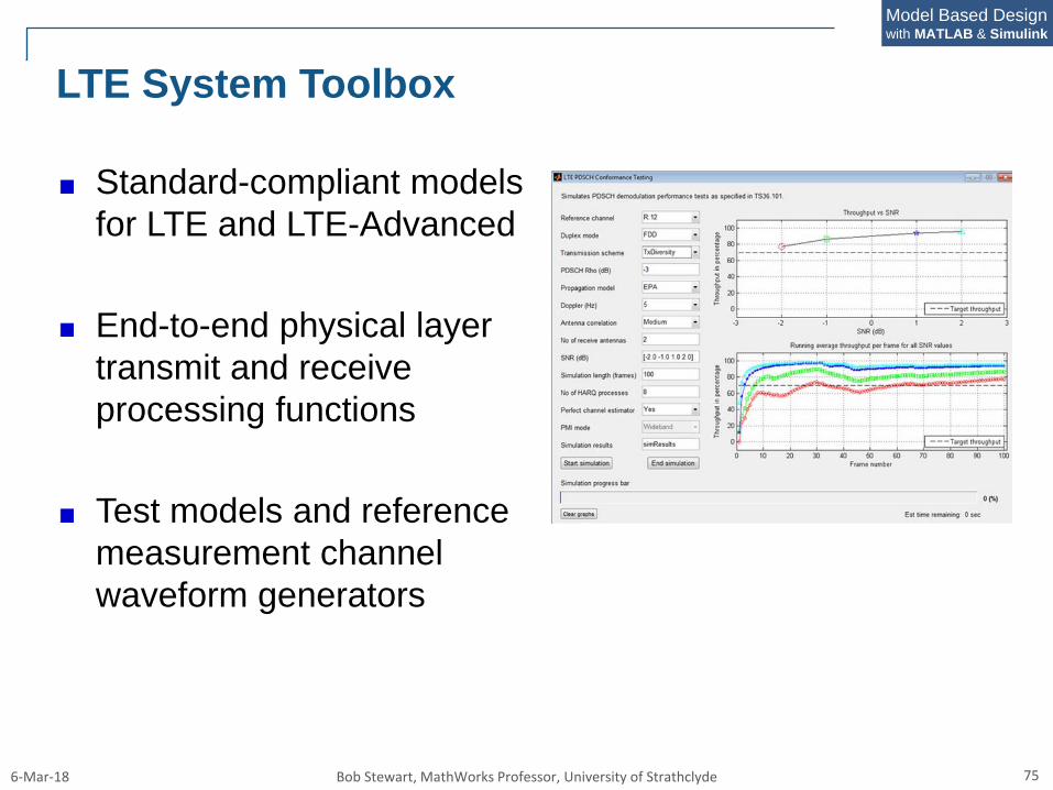
LTE System Toolbox
Standard-compliant models
for LTE and LTE-Advanced
End-to-end physical layer
transmit and receive
processing functions
Test models and reference
measurement channel
waveform generators
6-Mar-18 Bob Stewart, MathWorks Professor, University of Strathclyde 76
Model Based Designwith MATLAB & Simulink
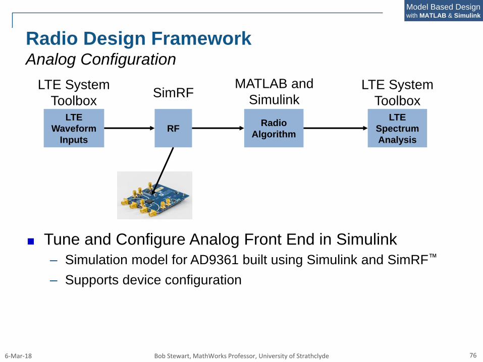
Radio Design FrameworkAnalog Configuration
Tune and Configure Analog Front End in Simulink
– Simulation model for AD9361 built using Simulink and SimRF™
– Supports device configuration
LTE
Waveform
Inputs
RFRadio
Algorithm
LTE
Spectrum
Analysis
SimRFMATLAB and
SimulinkLTE System
Toolbox
LTE System
Toolbox
6-Mar-18 Bob Stewart, MathWorks Professor, University of Strathclyde 77
Model Based Designwith MATLAB & Simulink
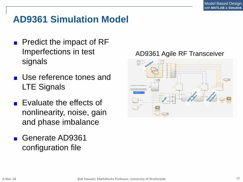
AD9361 Simulation Model
Predict the impact of RF
Imperfections in test
signals
Use reference tones and
LTE Signals
Evaluate the effects of
nonlinearity, noise, gain
and phase imbalance
Generate AD9361
configuration file
AD9361 Agile RF Transceiver
6-Mar-18 Bob Stewart, MathWorks Professor, University of Strathclyde 78
Model Based Designwith MATLAB & Simulink
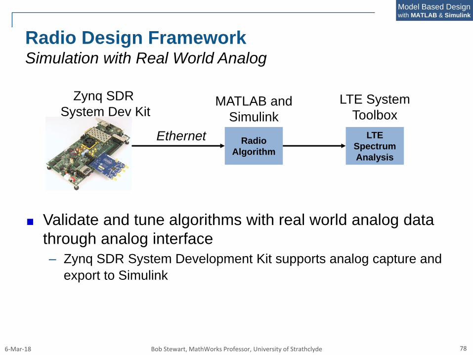
Radio Design FrameworkSimulation with Real World Analog
Validate and tune algorithms with real world analog data
through analog interface
– Zynq SDR System Development Kit supports analog capture and
export to Simulink
Radio
Algorithm
LTE
Spectrum
Analysis
Zynq SDR
System Dev KitLTE System
ToolboxMATLAB and
Simulink
Ethernet
6-Mar-18 Bob Stewart, MathWorks Professor, University of Strathclyde 79
Model Based Designwith MATLAB & Simulink
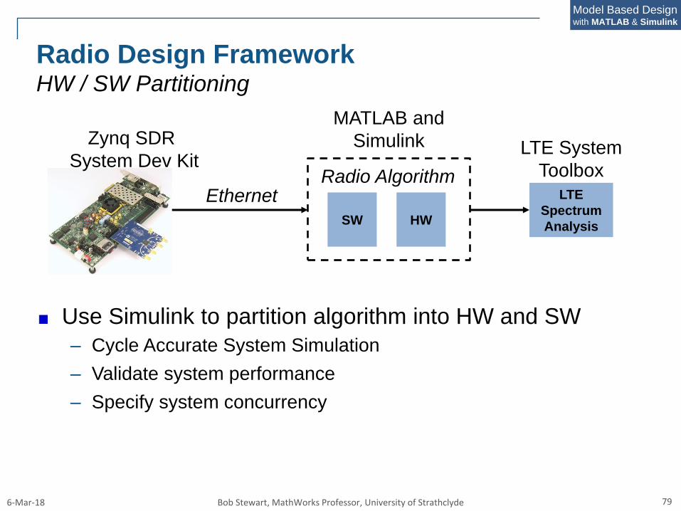
Radio Design FrameworkHW / SW Partitioning
Use Simulink to partition algorithm into HW and SW
– Cycle Accurate System Simulation
– Validate system performance
– Specify system concurrency
SW
LTE
Spectrum
Analysis
Zynq SDR
System Dev KitLTE System
Toolbox
MATLAB and
Simulink
Ethernet
HW
Radio Algorithm
6-Mar-18 Bob Stewart, MathWorks Professor, University of Strathclyde 80
Model Based Designwith MATLAB & Simulink
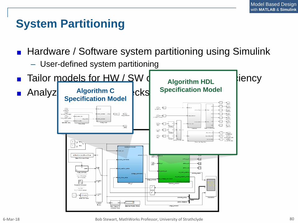
System Partitioning
Hardware / Software system partitioning using Simulink
– User-defined system partitioning
Tailor models for HW / SW code generation efficiency
Analyze system bottlenecks and refine resultsAlgorithm
C
Algorithm C
Specification Model
Algorithm HDL
Specification Model
6-Mar-18 Bob Stewart, MathWorks Professor, University of Strathclyde 81
Model Based Designwith MATLAB & Simulink
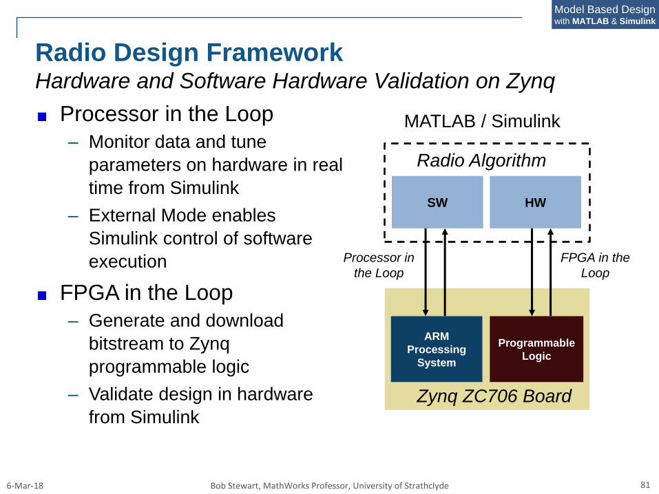
Radio Design FrameworkHardware and Software Hardware Validation on Zynq
Processor in the Loop
– Monitor data and tune
parameters on hardware in real
time from Simulink
– External Mode enables
Simulink control of software
execution
FPGA in the Loop
– Generate and download
bitstream to Zynq
programmable logic
– Validate design in hardware
from Simulink
SW
MATLAB / Simulink
HW
Radio Algorithm
ARM
Processing
System
Programmable
Logic
Zynq ZC706 Board
Processor in
the Loop
FPGA in the
Loop
6-Mar-18 Bob Stewart, MathWorks Professor, University of Strathclyde 82
Model Based Designwith MATLAB & Simulink
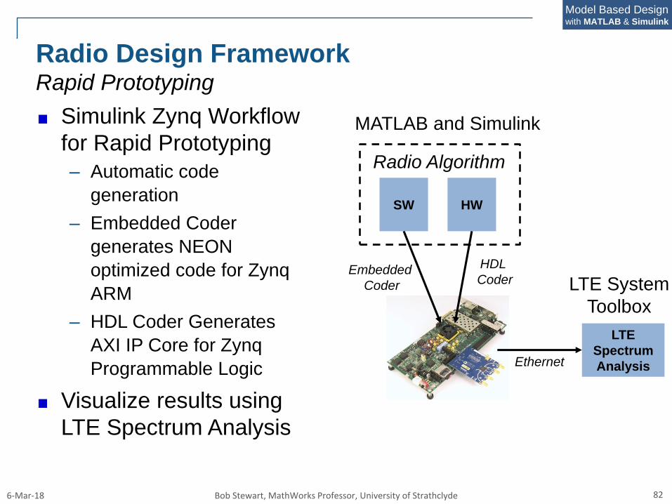
Radio Design FrameworkRapid Prototyping
Simulink Zynq Workflow
for Rapid Prototyping
– Automatic code
generation
– Embedded Coder
generates NEON
optimized code for Zynq
ARM
– HDL Coder Generates
AXI IP Core for Zynq
Programmable Logic
Visualize results using
LTE Spectrum Analysis
SW
LTE
Spectrum
Analysis
LTE System
Toolbox
MATLAB and Simulink
Ethernet
HW
Radio Algorithm
Embedded
Coder
HDL
Coder