Embed Size (px)
Citation preview

ModbusCommunication Guide
-2- v4.3
Index
Document version: v4.3 - 01/2016© Libelium Comunicaciones Distribuidas S.L.
INDEX
1. Introduction ......................................................................................................................................... 41.1. The standard ..................................................................................................................................................................................41.2. Master/Slave principle ................................................................................................................................................................41.3. Modbus data transmission .......................................................................................................................................................51.4. Modbus RTU frame ......................................................................................................................................................................5
2. Modbus over RS-485 and RS-232 ....................................................................................................... 62.1. Modbus over RS-232 ...................................................................................................................................................................62.2. Modbus over RS-485 ...................................................................................................................................................................6
3. Applications ......................................................................................................................................... 8
4. Master library functions ...................................................................................................................... 94.1. Configuring the master ..............................................................................................................................................................9
4.1.1. Library constructor .....................................................................................................................................................94.1.2. Begin function ...............................................................................................................................................................9
4.2. Modbus master library and function .................................................................................................................................104.2.1. Read Coils ......................................................................................................................................................................104.2.2. Read Discrete Inputs .................................................................................................................................................114.2.3. Write Single Coil ..........................................................................................................................................................114.2.4. Write Multiple Coils ....................................................................................................................................................124.2.5. Read Holding Registers ............................................................................................................................................124.2.6. Read Input Registers .................................................................................................................................................124.2.7. Write Single Register .................................................................................................................................................134.2.8. Write Multiple Registers ...........................................................................................................................................134.2.9. Mask Write Register .................................................................................................................................................134.2.10. Read and Write Multiple Registers .....................................................................................................................14
4.3. Another library functions .......................................................................................................................................................144.3.1. Retrieve data ................................................................................................................................................................144.3.2. Clear Response Buffer ..............................................................................................................................................14
5. Slave library functions ...................................................................................................................... 155.1. Library constructor ...................................................................................................................................................................155.2. Configuring the slave ..............................................................................................................................................................155.3. Saving data in registers ...........................................................................................................................................................16
6. Real applications ............................................................................................................................... 17
7. Code examples and extended information ..................................................................................... 20

-3- v4.3
8. API changelog .................................................................................................................................... 23
9. Documentation changelog ............................................................................................................... 24

-4- v4.3
Introduction
1. Introduction
1.1. The standardModbus is a serial communications protocol originally published by Schneider Electric in 1979 for use with their programmable logic controllers (PLCs). Modbus is located in the level 2 of the OSI model, and uses a master/slave (or client-server) architecture. Simple and robust, it has since become a de facto standard communication protocol, and it is now a commonly available means of connecting industrial electronic devices. Modbus communication protocol presents the follow features:
• It has been developed with industrial applications in mind • Openly published and royalty-free • Easy development and maintenance
Modbus allows communication between many devices connected to the same network, for example a system that measures temperature and humidity and communicates the results to a computer. Many of the data types are named from its use in driving relays: a single-bit physical output is called a coil, and a single-bit physical input is called a discrete input or a contact.
This list includes some of the most common uses of the standard:
• Multiple master-slave applications • Sensors and instruments • Industrial networking • Building and infrastructure • Transportation and energy applications
1.2. Master/Slave principleThe master / slave principle has the following characteristics:
• Only one master can be connected in a network. • One or more slaves can be connected at the same time in a network. • Only the master can initiate communication, i.e., sending requests to the slaves. • In Modbus communications, the master can only initiate one transaction simultaneously. • The slaves can only respond to requests from the master. • Slaves are not allowed to initiate communication with or the master or with any other slave. In Modbus communications,
slaves generate an error message and send it as a response to the master if an error has occurred in the reception of a message or the slave can not perform the requested action.
-5- v4.3
Introduction
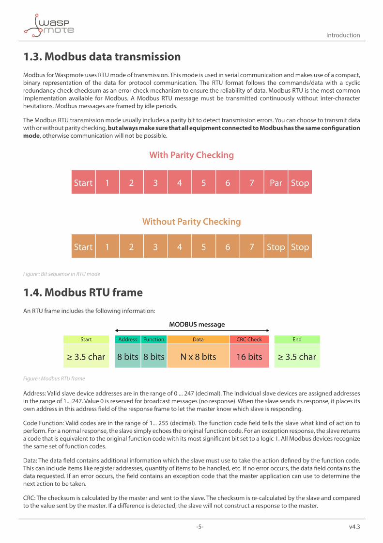
1.3. Modbus data transmissionModbus for Waspmote uses RTU mode of transmission. This mode is used in serial communication and makes use of a compact, binary representation of the data for protocol communication. The RTU format follows the commands/data with a cyclic redundancy check checksum as an error check mechanism to ensure the reliability of data. Modbus RTU is the most common implementation available for Modbus. A Modbus RTU message must be transmitted continuously without inter-character hesitations. Modbus messages are framed by idle periods.
The Modbus RTU transmission mode usually includes a parity bit to detect transmission errors. You can choose to transmit data with or without parity checking, but always make sure that all equipment connected to Modbus has the same configuration mode, otherwise communication will not be possible.
Figure : Bit sequence in RTU mode
1.4. Modbus RTU frameAn RTU frame includes the following information:
Figure : Modbus RTU frame
Address: Valid slave device addresses are in the range of 0 ... 247 (decimal). The individual slave devices are assigned addresses in the range of 1... 247. Value 0 is reserved for broadcast messages (no response). When the slave sends its response, it places its own address in this address field of the response frame to let the master know which slave is responding.
Code Function: Valid codes are in the range of 1... 255 (decimal). The function code field tells the slave what kind of action to perform. For a normal response, the slave simply echoes the original function code. For an exception response, the slave returns a code that is equivalent to the original function code with its most significant bit set to a logic 1. All Modbus devices recognize the same set of function codes.
Data: The data field contains additional information which the slave must use to take the action defined by the function code. This can include items like register addresses, quantity of items to be handled, etc. If no error occurs, the data field contains the data requested. If an error occurs, the field contains an exception code that the master application can use to determine the next action to be taken.
CRC: The checksum is calculated by the master and sent to the slave. The checksum is re-calculated by the slave and compared to the value sent by the master. If a difference is detected, the slave will not construct a response to the master.
-6- v4.3
Modbus over RS-485 and RS-232
2. Modbus over RS-485 and RS-232The Modbus protocol can be implemented over RS-485 and RS-232 physical layers. The Waspmote platform provides the necessary hardware and software for working with both protocols. The name and use of the functions are the same for RS-232 and RS-485, and the only changes are the library to include and the instantiation of the object. The differences between the two standards are explained in the corresponding communication guides.
Note: Both RS-232 module and RS-485 module can implement Modbus since, it is simply a software layer built on top the physical layer. That is why we suggest to start developing in RS-232 or RS-485, and after this, continue with Modbus.
The Modbus library has been tested with various devices and is compatible with the majority of commercial modules, but this does not ensure the working with all of them. Be sure that the Modbus module fits your technical requirements. The final user is the responsible to perform the task of communicating the Modbus module with other commercial devices.
2.1. Modbus over RS-232The first step to use Modbus over RS-232 is to include the corresponding libraries and instantiate the necessary objects. Below you can see how to include these libraries.
Example of how to include the neccesary libraries:
// Include these libraries for using the RS-232 and Modbus functions#include <Wasp232.h>#include <ModbusMaster232.h>
After including libraries, you have to instantiate a ModbusMaster object. Below you can see that an object called “slave” has been created in the address “1” (in the assumption that an actual Modbus slave is connected in that address). When the master needs to communicate with the address “1”, it must use this object.
// Instantiate ModbusMaster object as slave ID 1ModbusMaster232 slave(1);
Example of code to run in slaves nodes:
// Include these libraries for using the RS-232 and Modbus functions#include <Wasp232.h>#include <ModbusSlave232.h>
After including the libraries, you have to instantiate a ModbusSlave object.
// Create new Modbus instanceModbusSlave232 mbs;
2.2. Modbus over RS-485The first step to use Modbus over RS-485 is to include the corresponding libraries and instantiate the necessary objects. Below you can see the complete process.
Example of use in master mode:
// Include these libraries for using the RS-485 and Modbus functions#include <Wasp485.h>#include <ModbusMaster485.h>

-7- v4.3
Modbus over RS-485 and RS-232
After including libraries, you have to instantiate a ModbusMaster object. Below you can see that an object called “slave” has been created in the address “1” (in the assumption that an actual Modbus slave is connected in that address). When the master needs to communicate with the address “1”, it must use this object.
// Instantiate ModbusMaster object as slave ID 1ModbusMaster485 node(1);
Example of use in slave mode:
// Include these libraries for using the RS-485 and Modbus functions#include <Wasp485.h>#include <ModbusSlave485.h>
After including the libraries, you have to instantiate a ModbusSlave object.
// Create new mbs instanceModbusSlave485 mbs;
-8- v4.3
Applications
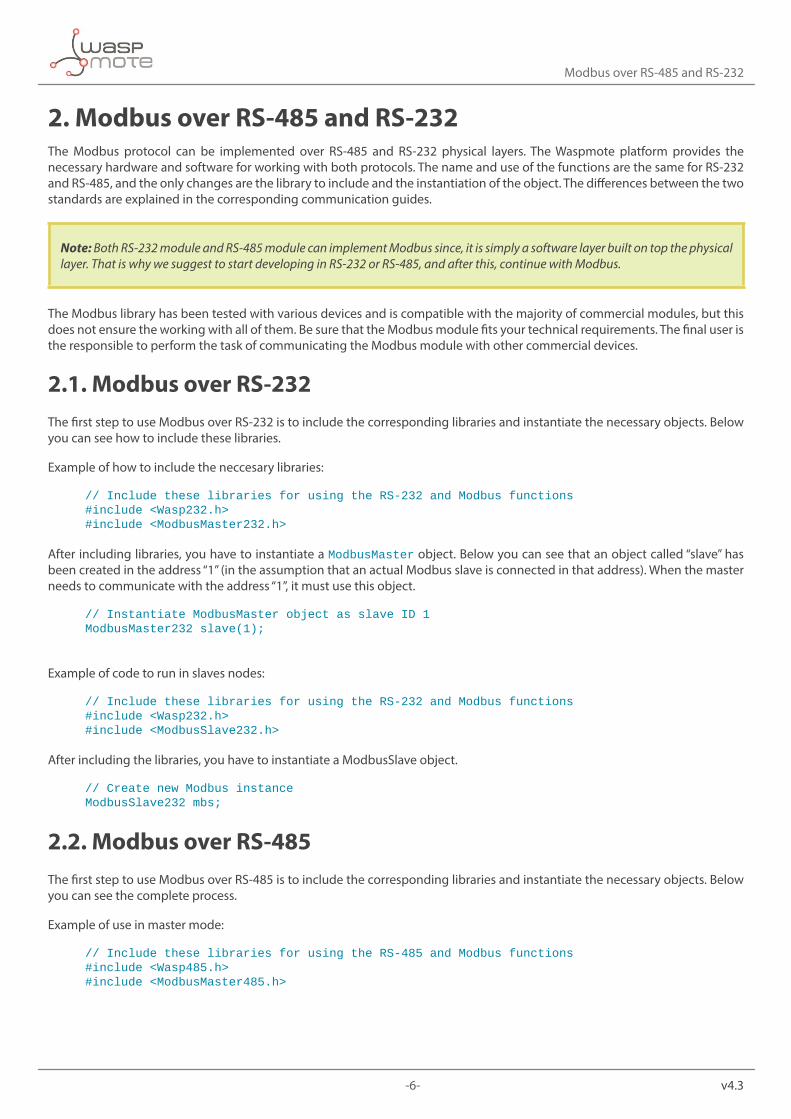
3. ApplicationsThis module allows the user to interface the Waspmote ecosystem with Modbus systems. Waspmote allows to perform three main applications:
1º- Connect any sensor to an existing Modbus device/networkWaspmote can be configured to work as a node in the network, inserting sensor data into the Modbus bus already present. Waspmote can obtain information from more than 70 sensors which are currently integrated in the platform by using specific sensor boards (e.g: CO, CO2, temperature, humidity, acceleration, pH, IR, luminosity, etc). This way, the sensor information can be read from any Modbus device connected to the bus.
Figure : Waspmote integrated in a Modbus network
2º- Add wireless connectivity to Modbus devicesWaspmote can be configured to read the information coming from the Modbus bus and send it wirelessly using any of the wireless modules available in the platform to a base station or even directly to a Cloud server. The available wireless technologies are: WiFi, 3G, GPRS, 802.15.4, ZigBee, LoRaWAN, LoRa, Sigfox, Bluetooth, Bluetooth Low Energy, RF-868MHz, RF-900MHz.
Figure : Modbus wireless connectivity
3º- Connect to the Cloud Modbus devicesWaspmote can be configured to read the information coming from Modbus devices and send it wirelessly directly to the Cloud using WiFi, 3G and GPRS radio interfaces.
Figure : Cloud connection
-9- v4.3
Master library functions
4. Master library functions
4.1. Configuring the masterThe configuration of the master is very important before starting the communication with the slaves. Be sure that your devices can be used with the Waspmote Modbus protocol. For example, the baud rate must be in the available range of Waspmote and the communication must be 8N1 (8 bits, 1 stop bit, no parity).
4.1.1. Library constructor
Before using the library, an object of the library must be created. This object will assign the physical address of the slave. This address can take values from 0 to 255 (address 0 is normally for broadcast mode). In a network, this address must be unique for each device.
Example of use:
{ // Instantiate ModbusMaster object as slave ID 1 ModbusMaster485 node(1);}
You can create an object for managing several slaves in an easy way.
Example of use:
{ // Instantiate ModbusMaster object as slave ID 1 ModbusMaster485 temperatureSensor(1); // Instantiate ModbusMaster object as slave ID 2 ModbusMaster485 co2Sensor(2);}
4.1.2. Begin function
In the begin() function, the baud rate communication must be configured. This baud rate must be one of the standard values mentioned in the RS-485 and RS-232 guides. If the value is not a standard value, the device will be configured at 1200 bps.
We suggest to study the RS-232 or RS-485 Communication Guides to know how to configure these modules.
-10- v4.3
Master library functions
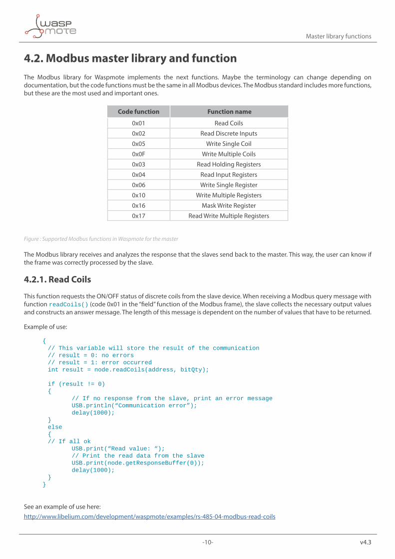
4.2. Modbus master library and functionThe Modbus library for Waspmote implements the next functions. Maybe the terminology can change depending on documentation, but the code functions must be the same in all Modbus devices. The Modbus standard includes more functions, but these are the most used and important ones.
Code function Function name
0x01 Read Coils
0x02 Read Discrete Inputs
0x05 Write Single Coil
0x0F Write Multiple Coils
0x03 Read Holding Registers
0x04 Read Input Registers
0x06 Write Single Register
0x10 Write Multiple Registers
0x16 Mask Write Register
0x17 Read Write Multiple Registers
Figure : Supported Modbus functions in Waspmote for the master
The Modbus library receives and analyzes the response that the slaves send back to the master. This way, the user can know if the frame was correctly processed by the slave.
4.2.1. Read Coils
This function requests the ON/OFF status of discrete coils from the slave device. When receiving a Modbus query message with function readCoils() (code 0x01 in the “field” function of the Modbus frame), the slave collects the necessary output values and constructs an answer message. The length of this message is dependent on the number of values that have to be returned.
Example of use:
{ // This variable will store the result of the communication // result = 0: no errors // result = 1: error occurred int result = node.readCoils(address, bitQty);
if (result != 0) { // If no response from the slave, print an error message USB.println(“Communication error”); delay(1000); } else { // If all ok USB.print(“Read value: “); // Print the read data from the slave USB.print(node.getResponseBuffer(0)); delay(1000); }}
See an example of use here:http://www.libelium.com/development/waspmote/examples/rs-485-04-modbus-read-coils
-11- v4.3
Master library functions
4.2.2. Read Discrete Inputs
Reading input values with Modbus is done in the same way as reading the status of coils. The only difference is that for inputs, Modbus function readDiscreteInput() is used (code 0x02). Like with coils, the address of the first input, and the number of inputs to read must be put in the data field of the query message. After receiving a query message with Modbus function readDiscreteInput(), the slave puts the requested input values in a message structure and sends this message back to the Modbus master. The length of the message depends on the number of input values returned.
Example of use:
{ // This variable will store the result of the communication // result = 0: no errors // result = 1: error occurred int result = node.readDiscreteInputs(address, bitQty);
if (result != 0) { // If no response from the slave, print an error message USB.println(“Communication error”); delay(1000); } else { // If all OK USB.print(“Read value: “); // Print the read data from the slave USB.print(node.getResponseBuffer(0)); delay(1000); }}
4.2.3. Write Single Coil
This function writes a single coil to either ON or OFF. The request message specifies the coil address to be written. The requested ON / OFF state is specified by a constant in the request data field. The normal response is an echo of the request, returned after the coil state has been written.
Example of use:
{ // This variable will store the result of the communication // result = 0: no errors // result = 1: error occurred int result = node.writeSingleCoil(address, bitData);
if (result != 0) { // If no response from the slave, print an error message USB.println(“Communication error”); delay(100); } else { // If all OK USB.print(“Data writted successfully”); delay(100); }}
See an example of use here:http://www.libelium.com/development/waspmote/examples/rs-485-06-modbus-write-single-coil
-12- v4.3
Master library functions
4.2.4. Write Multiple Coils
This Modbus function code is used to write each coil in a sequence of coils to either ON or OFF in a remote slave. The request specifies the coil references to be forced. Coils are addressed starting at zero, therefore coil numbered 1 is addressed as 0. The requested ON/OFF states are specified by contents of the request data field. A logical ‘1’ in a bit position of the field requests the corresponding output to be ON. A logical ‘0’ requests it to be OFF.
{ // Write data in the transmission buffer, for writing it in the slave node.setTransmitBuffer(0,ON);//ONdefinedpreviously node.setTransmitBuffer(1,OFF);//OFFdefinedpreviously node.setTransmitBuffer(2, ON);
// This variable will store the result of the communication // result = 0: no errors // result = 1: error occurred int result = node.writeMultipleCoils(address, byteQty); delay(100);}
4.2.5. Read Holding Registers
This function is used to read the contents of a contiguous block of holding registers in a slave The request specifies the starting register address and the number of registers. In the registers are addressed starting at zero. Therefore registers numbered 1-16 are addressed as 0-15. The register data in the response message are packed as two bytes per register.
Example of use:
{ // This variable will store the result of the communication // result = 0: no errors // result = 1: error occurred //Read 4 bytes int result = node.readHoldingRegisters(accX, bytesQty);}
4.2.6. Read Input Registers
This function code is used to read contiguous input registers in a slave. The Request PDU specifies the starting register address and the number of registers. The registers are addressed starting at zero. The register data in the response message are packed as two bytes per register, with the binary contents right justified within each byte. For each register, the first byte contains the high order bits and the second contains the low order bits.
Example of use:
{ // This variable will store the result of the communication // result = 0: no errors // result = 1: error occurred int result = node.readInputRegisters(address, bytesQty);}
See an example of use here:http://www.libelium.com/development/waspmote/examples/rs-485-05-modbus-read-input-registers
-13- v4.3
Master library functions
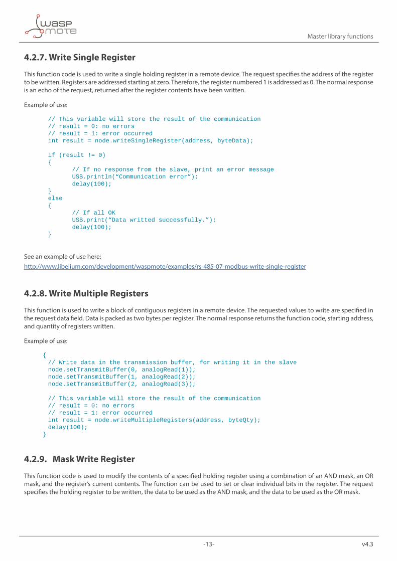
4.2.7. Write Single Register
This function code is used to write a single holding register in a remote device. The request specifies the address of the register to be written. Registers are addressed starting at zero. Therefore, the register numbered 1 is addressed as 0. The normal response is an echo of the request, returned after the register contents have been written.
Example of use:
// This variable will store the result of the communication // result = 0: no errors // result = 1: error occurred int result = node.writeSingleRegister(address, byteData);
if (result != 0) { // If no response from the slave, print an error message USB.println(“Communication error”); delay(100); } else { // If all OK USB.print(“Data writted successfully.”); delay(100); }
See an example of use here: http://www.libelium.com/development/waspmote/examples/rs-485-07-modbus-write-single-register
4.2.8. Write Multiple Registers
This function is used to write a block of contiguous registers in a remote device. The requested values to write are specified in the request data field. Data is packed as two bytes per register. The normal response returns the function code, starting address, and quantity of registers written.
Example of use:
{ // Write data in the transmission buffer, for writing it in the slave node.setTransmitBuffer(0, analogRead(1)); node.setTransmitBuffer(1, analogRead(2)); node.setTransmitBuffer(2, analogRead(3));
// This variable will store the result of the communication // result = 0: no errors // result = 1: error occurred int result = node.writeMultipleRegisters(address, byteQty); delay(100);}
4.2.9. Mask Write Register
This function code is used to modify the contents of a specified holding register using a combination of an AND mask, an OR mask, and the register’s current contents. The function can be used to set or clear individual bits in the register. The request specifies the holding register to be written, the data to be used as the AND mask, and the data to be used as the OR mask.
-14- v4.3
Master library functions
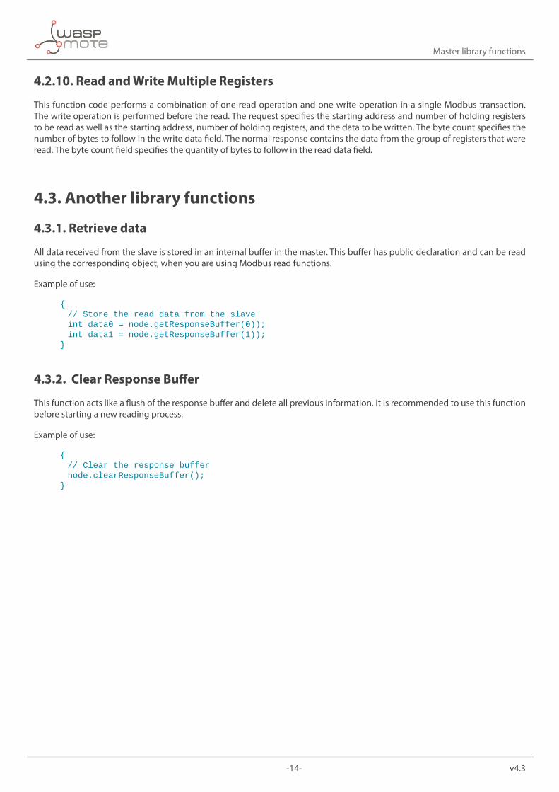
4.2.10. Read and Write Multiple Registers
This function code performs a combination of one read operation and one write operation in a single Modbus transaction. The write operation is performed before the read. The request specifies the starting address and number of holding registers to be read as well as the starting address, number of holding registers, and the data to be written. The byte count specifies the number of bytes to follow in the write data field. The normal response contains the data from the group of registers that were read. The byte count field specifies the quantity of bytes to follow in the read data field.
4.3. Another library functions
4.3.1. Retrieve data
All data received from the slave is stored in an internal buffer in the master. This buffer has public declaration and can be read using the corresponding object, when you are using Modbus read functions.
Example of use:
{ // Store the read data from the slave int data0 = node.getResponseBuffer(0)); int data1 = node.getResponseBuffer(1));}
4.3.2. Clear Response Buffer
This function acts like a flush of the response buffer and delete all previous information. It is recommended to use this function before starting a new reading process.
Example of use:
{ // Clear the response buffer node.clearResponseBuffer();}
-15- v4.3
Slave library functions
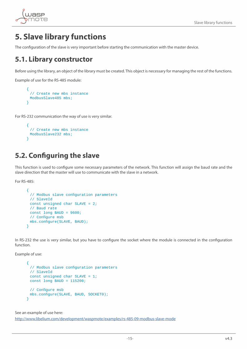
5. Slave library functionsThe configuration of the slave is very important before starting the communication with the master device.
5.1. Library constructorBefore using the library, an object of the library must be created. This object is necessary for managing the rest of the functions.
Example of use for the RS-485 module:
{ // Create new mbs instance ModbusSlave485 mbs;}
For RS-232 communication the way of use is very similar.
{ // Create new mbs instance ModbusSlave232 mbs;}
5.2. Configuring the slaveThis function is used to configure some necessary parameters of the network. This function will assign the baud rate and the slave direction that the master will use to communicate with the slave in a network.
For RS-485:
{ //Modbusslaveconfigurationparameters // SlaveId const unsigned char SLAVE = 2; // Baud rate const long BAUD = 9600; //Configuremsb mbs.configure(SLAVE,BAUD);}
In RS-232 the use is very similar, but you have to configure the socket where the module is connected in the configuration function.
Example of use:
{ //Modbusslaveconfigurationparameters // SlaveId const unsigned char SLAVE = 1; const long BAUD = 115200;
//Configuremsb mbs.configure(SLAVE,BAUD,SOCKET0);}
See an example of use here: http://www.libelium.com/development/waspmote/examples/rs-485-09-modbus-slave-mode

-16- v4.3
Slave library functions
5.3. Saving data in registersTo use Waspmote as a Modbus slave device you need create some specific registers to exchange information. These registers are used to read or write the information sent by the master device, depending on the operation. Waspmote slave library only accepts the next Modbus functions:
Code function Function name
0x03 Read Holding Registers
0x06 Write Single Register
0x10 Write Multiple Registers
Figure : Supported Modbus functions in Waspmote for the slave
These registers can be used to store information, for example from the sensors connected to Waspmote.
Example of use:
// Global bufferint regs[MB_REGS];
{ // Pass current register values to mbs mbs.update(regs, MB_REGS);
// Read all the analog Inputs, and store the values in // the Modbus registers regs[MB_0] = ACC.getX(); // X Value regs[MB_1] = ACC.getY(); // Y Value regs[MB_2] = ACC.getZ(); // Z Value regs[MB_3] = PWR.getBatteryLevel(); // Batery level}
The function updates the current values of the registers in the Modbus slave object. These registers can also be written from the master device and used for example, to activate a digital output or to configure some parameters of the slave.
This function is useful for controlling what values the user wants to make available for the master.
See an example of use here:http://www.libelium.com/development/waspmote/examples/rs-485-10-modbus-slave-acc-battery-level
-17- v4.3
Real applications
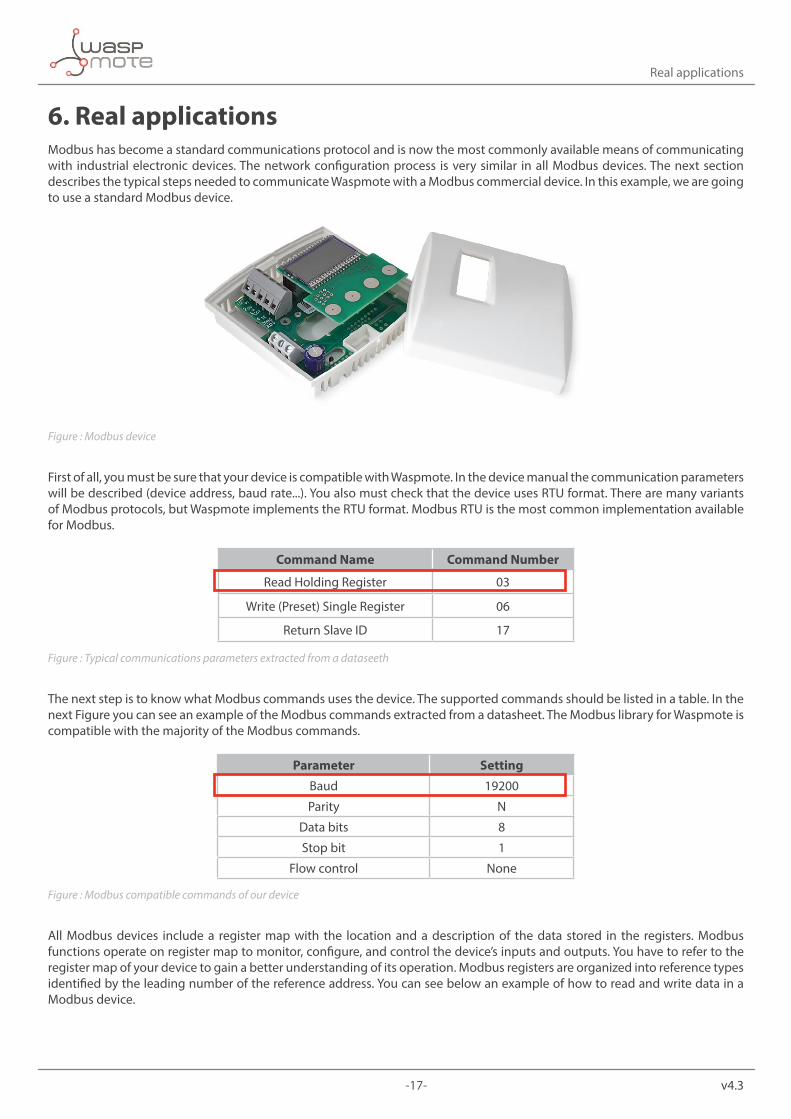
6. Real applicationsModbus has become a standard communications protocol and is now the most commonly available means of communicating with industrial electronic devices. The network configuration process is very similar in all Modbus devices. The next section describes the typical steps needed to communicate Waspmote with a Modbus commercial device. In this example, we are going to use a standard Modbus device.
Figure : Modbus device
First of all, you must be sure that your device is compatible with Waspmote. In the device manual the communication parameters will be described (device address, baud rate...). You also must check that the device uses RTU format. There are many variants of Modbus protocols, but Waspmote implements the RTU format. Modbus RTU is the most common implementation available for Modbus.
Command Name Command Number
Read Holding Register 03
Write (Preset) Single Register 06
Return Slave ID 17
Figure : Typical communications parameters extracted from a dataseeth
The next step is to know what Modbus commands uses the device. The supported commands should be listed in a table. In the next Figure you can see an example of the Modbus commands extracted from a datasheet. The Modbus library for Waspmote is compatible with the majority of the Modbus commands.
Parameter Setting
Baud 19200
Parity N
Data bits 8
Stop bit 1
Flow control None
Figure : Modbus compatible commands of our device
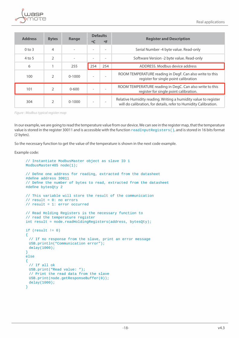
All Modbus devices include a register map with the location and a description of the data stored in the registers. Modbus functions operate on register map to monitor, configure, and control the device’s inputs and outputs. You have to refer to the register map of your device to gain a better understanding of its operation. Modbus registers are organized into reference types identified by the leading number of the reference address. You can see below an example of how to read and write data in a Modbus device.
-18- v4.3
Real applications
Address Bytes RangeDefaults
Register and DescriptionºC ºF
0 to 3 4 - - - Serial Number -4 byte value. Read-only
4 to 5 2 - - - Software Version -2 byte value. Read-only
6 1 255 254 254 ADDRESS. Modbus device address
100 2 0-1000 - - ROOM TEMPERATURE reading in DegF. Can also write to this register for single point calibration
101 2 0-600 - - ROOM TEMPERATURE reading in DegC. Can also write to this register for single point calibration.
304 2 0-1000 - - Relative Humidity reading. Writing a humidity value to register will do calibration, for details, refer to Humidity Calibration.
Figure : Modbus typical register map
In our example, we are going to read the temperature value from our device. We can see in the register map, that the temperature value is stored in the register 30011 and is accessible with the function readInputRegisters(), and is stored in 16 bits format (2 bytes).
So the necessary function to get the value of the temperature is shown in the next code example.
Example code:
// Instantiate ModbusMaster object as slave ID 1ModbusMaster485 node(1);
//Defineoneaddressforreading,extractedfromthedatasheet#defineaddress30011//Definethenumberofbytestoread,extractedfromthedatasheet#definebytesQty2
// This variable will store the result of the communication// result = 0: no errors// result = 1: error occurred
// Read Holding Registers is the necessary function to// read the temperature registerint result = node.readHoldingRegisters(address, bytesQty);
if (result != 0){ // If no response from the slave, print an error message USB.println(“Communication error”); delay(1000);}else{ // If all ok USB.print(“Read value: “); // Print the read data from the slave USB.print(node.getResponseBuffer(0)); delay(1000);}

-19- v4.3
Real applications
The last step is to make the physically connection between the Modbus device and Waspmote. Our device uses RS-485 physical layer and uses a differential line transmission. The name of the lines can change. In many devices are named A/B, or +/-.
Figure : Waspmote RS-485 module connecting to a Modbus device
If the communication has been established, you should be able to see the temperature data in your serial monitor. If the communication with the device is not correct you should view an error message. You can use this error message to make retries and as a feedback of the state of your network.
In the next section and in the development section of the web, there is a complete example if how to configure Waspmote and the RS-485 module in a wireless application.
-20- v4.3
Code examples and extended information
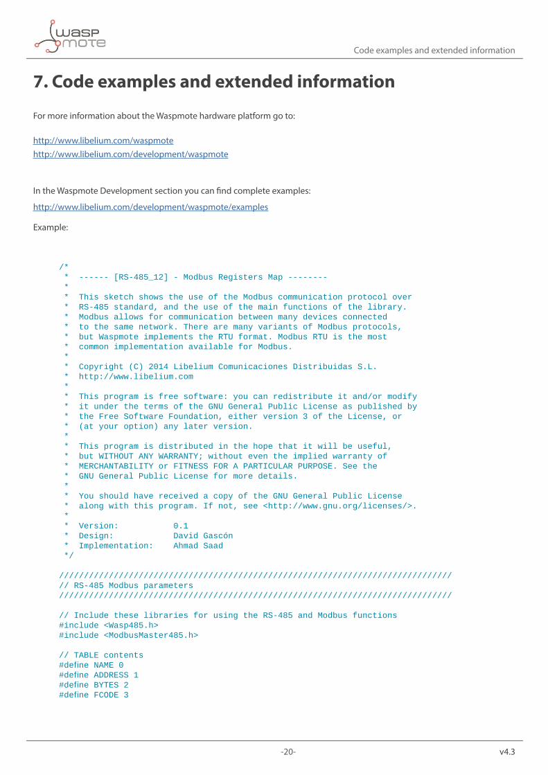
7. Code examples and extended information
For more information about the Waspmote hardware platform go to:
http://www.libelium.com/waspmotehttp://www.libelium.com/development/waspmote
In the Waspmote Development section you can find complete examples:
http://www.libelium.com/development/waspmote/examples
Example:
/* * ------ [RS-485_12] - Modbus Registers Map -------- * * This sketch shows the use of the Modbus communication protocol over * RS-485 standard, and the use of the main functions of the library. * Modbus allows for communication between many devices connected * to the same network. There are many variants of Modbus protocols, * but Waspmote implements the RTU format. Modbus RTU is the most * common implementation available for Modbus. * * Copyright (C) 2014 Libelium Comunicaciones Distribuidas S.L. * http://www.libelium.com * * This program is free software: you can redistribute it and/or modify * it under the terms of the GNU General Public License as published by * the Free Software Foundation, either version 3 of the License, or * (at your option) any later version. * * This program is distributed in the hope that it will be useful, * but WITHOUT ANY WARRANTY; without even the implied warranty of * MERCHANTABILITY or FITNESS FOR A PARTICULAR PURPOSE. See the * GNU General Public License for more details. * * You should have received a copy of the GNU General Public License * along with this program. If not, see <http://www.gnu.org/licenses/>. * * Version: 0.1 * Design: David Gascón * Implementation: Ahmad Saad */
///////////////////////////////////////////////////////////////////////////////// RS-485 Modbus parameters///////////////////////////////////////////////////////////////////////////////
// Include these libraries for using the RS-485 and Modbus functions#include <Wasp485.h>#include <ModbusMaster485.h>
// TABLE contents#defineNAME0#defineADDRESS1#defineBYTES2#defineFCODE3
-21- v4.3
Code examples and extended information
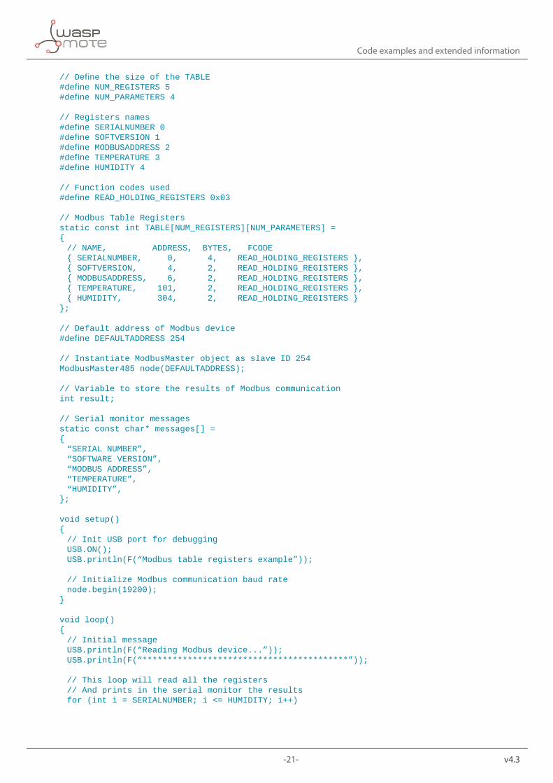
//DefinethesizeoftheTABLE#defineNUM_REGISTERS5#defineNUM_PARAMETERS4
// Registers names#defineSERIALNUMBER0#defineSOFTVERSION1#defineMODBUSADDRESS2#defineTEMPERATURE3#defineHUMIDITY4
// Function codes used#defineREAD_HOLDING_REGISTERS0x03
// Modbus Table Registersstatic const int TABLE[NUM_REGISTERS][NUM_PARAMETERS] ={ // NAME, ADDRESS, BYTES, FCODE { SERIALNUMBER, 0, 4, READ_HOLDING_REGISTERS }, { SOFTVERSION, 4, 2, READ_HOLDING_REGISTERS }, { MODBUSADDRESS, 6, 2, READ_HOLDING_REGISTERS }, { TEMPERATURE, 101, 2, READ_HOLDING_REGISTERS }, { HUMIDITY, 304, 2, READ_HOLDING_REGISTERS }};
// Default address of Modbus device#defineDEFAULTADDRESS254
// Instantiate ModbusMaster object as slave ID 254ModbusMaster485 node(DEFAULTADDRESS);
// Variable to store the results of Modbus communicationint result;
// Serial monitor messagesstatic const char* messages[] ={ “SERIAL NUMBER”, “SOFTWARE VERSION”, “MODBUS ADDRESS”, “TEMPERATURE”, “HUMIDITY”,};
void setup(){ // Init USB port for debugging USB.ON(); USB.println(F(“Modbustableregistersexample”));
//InitializeModbuscommunicationbaudrate node.begin(19200);}
void loop(){ // Initial message USB.println(F(“Reading Modbus device...”)); USB.println(F(“*****************************************”));
// This loop will read all the registers // And prints in the serial monitor the results for (int i = SERIALNUMBER; i <= HUMIDITY; i++)
-22- v4.3
Code examples and extended information
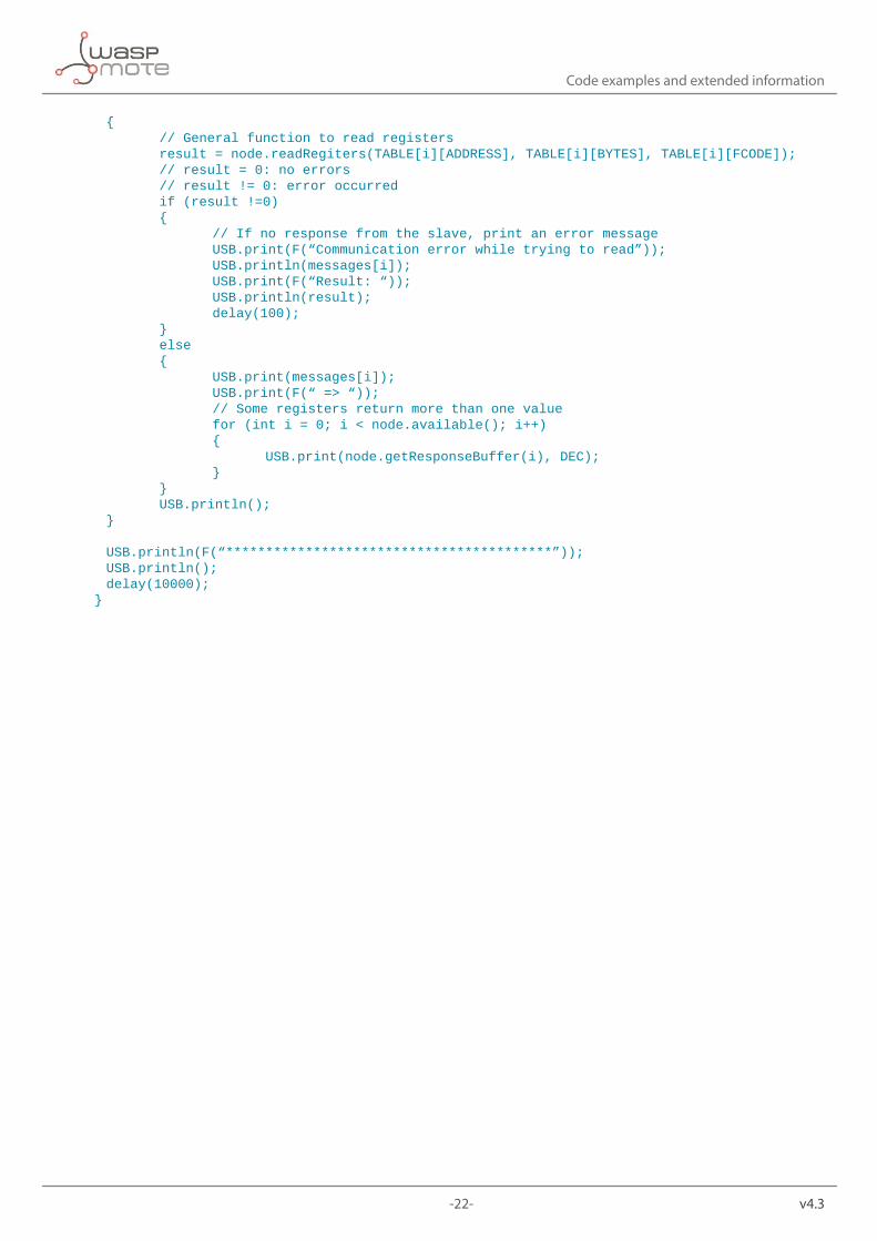
{ // General function to read registers result = node.readRegiters(TABLE[i][ADDRESS], TABLE[i][BYTES], TABLE[i][FCODE]); // result = 0: no errors // result != 0: error occurred if (result !=0) { // If no response from the slave, print an error message USB.print(F(“Communication error while trying to read”)); USB.println(messages[i]); USB.print(F(“Result: “)); USB.println(result); delay(100); } else { USB.print(messages[i]); USB.print(F(“ => “)); // Some registers return more than one value for (int i = 0; i < node.available(); i++) { USB.print(node.getResponseBuffer(i), DEC); } } USB.println(); }
USB.println(F(“*****************************************”)); USB.println(); delay(10000);}

-23- v4.3
API changelog
8. API changelogKeep track of the software changes on this link:
www.libelium.com/development/waspmote/documentation/changelog/#Modbus

-24- v4.3
Documentation changelog
9. Documentation changelogFrom v4.2 to v4.3
• References to the new LoRaWAN module From v4.1 to v4.2
• References to the new Sigfox module
From v4.0 to v4.1
• References to the new LoRa module • Created new chapter “API changelog”