Embed Size (px)
Citation preview
MoCA Installation and Troubleshooting Reference Guide
Overview
Introduction This document contains installation guidelines, performance verification steps, and troubleshooting measures for devices that support a multi-room network over Multimedia over Coax Alliance (MoCA™). Multi-room networks allow client devices (non-DVR set-tops) to stream content from a server device (DVR set-top) that has recorded linear content.
Features Support is provided for the following features on each MoCA device:
Standard Definition (SD) and High Definition (HD) content
Streaming rates of up to 100 Mbps
Trick modes (FF, REW, SLO-MO, and PAUSE)
Up to three clients per server
MoCA Devices The information in this guide applies to the following MoCA devices:
DVRs 8642HD and 8642HDC set-tops
8652HD and 8652HDC set-tops
Non-DVRs 4642HD and 4642HDC set-tops
4652HD and 4652HDC set-tops
1642HD and 1642HDC set-tops
2 4031235 Rev B
Overview
Purpose After reading this document, the reader will understand where to install the MoCA POE (Point of Entry) filter and MoCA set-tops with respect to cable splitters and amplifiers. The reader will also be able to verify links between MoCA set-tops and troubleshoot faulty installations.
Audience This document is intended for field technicians. [
Document Version This is the second formal release of this document.
In This Document Installation Basics ....................................................................................................... 3 Home Wiring Examples ............................................................................................. 4 Performance Verification ........................................................................................... 7 Preventing Interference with Cable Modems ....................................................... 12 Installation Problems ................................................................................................ 13 Troubleshooting ........................................................................................................ 19 Appendix A ............................................................................................................... 21 Appendix B ................................................................................................................ 25
4031235 Rev B 3
Installation Basics
Installation Basics A basic installation procedure involves the following:
Install the MoCA Point of Entry (POE) filter
Check QAM levels at each outlet
Boot the set-tops and verify the MoCA links
These topics are covered in the following sections.
Install POE Filter The POE filter (see MoCA Point of Entry Filter Data Sheet (part number 7016817)) is a 1002 MHz low-pass filter which is installed at the subscriber drop. It prevents interference between MoCA devices in homes connected to the same tap. As shown in Basic Installation (on page 4), the POE filter should be connected between the ground block and the splitter.
Verify QAM Levels Verify that the QAM signal level of the highest frequency QAM channel (i. e., channel 158) is adequate at each outlet used in the installation. If this is not the case, the home wiring should be corrected before continuing.
Verify MoCA Links Set-tops should automatically form a MoCA network after two or more MoCA devices boot up. Once a set-top has joined the network, its MoCA link indicator* will illuminate (see the front panel call-outs in the set-top guides listed below):
Cisco Explorer 8640HD, 8642HD, 8650HD, and 8652HD High-Definition DVR Set-Tops Quick Reference (part number 4026879)
Cisco Explorer 8640HDC, 8642HDC, 8650HDC, and 8652HDC High-Definition Set-Tops with Multi-Stream CableCARD (M-Card) Interface Quick Reference (part number 4026878)
Cisco Explorer 4642HD and 4652HD High-Definition Set-Tops Quick Reference (part number 4029078)
Cisco Explorer 4642HDC and 4652HDC High-Definition Set-Tops with Multi-Stream CableCARD Interface Quick Reference (part number 4029076)
* The 164x set-tops do not have a MoCA indicator. To verify the MoCA link, you must refer to DRIVERS - MoCA SUMMARY PG 1 (see Node Summary and Network Summary (on page 8)).
4 4031235 Rev B
Home Wiring Examples
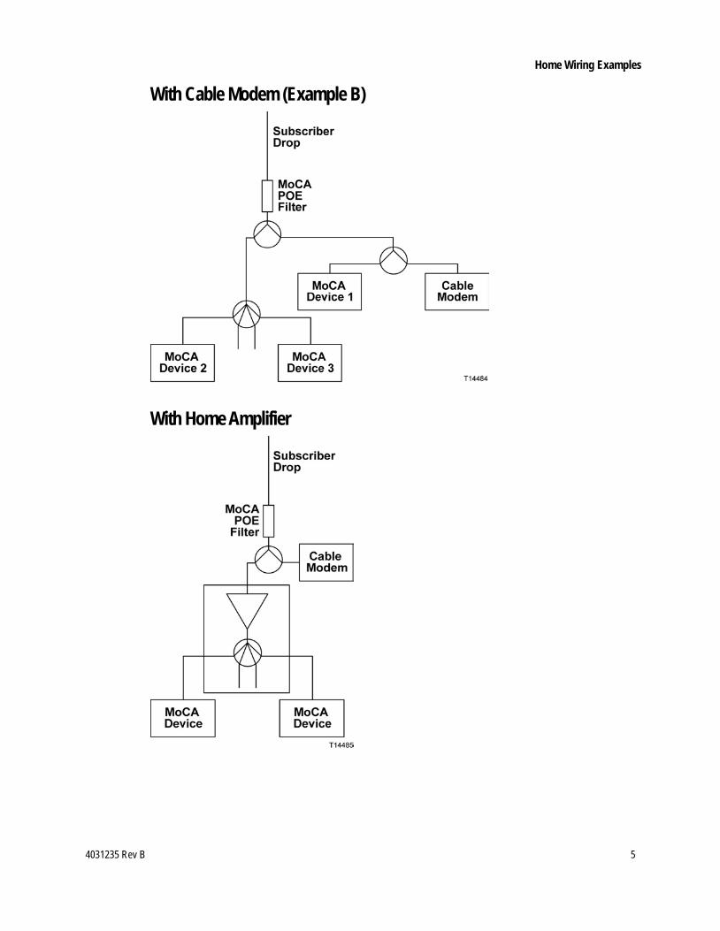
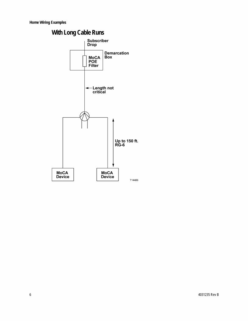
Home Wiring Examples The diagrams in this section show home wiring examples that typically provide good MoCA performance.
Note: As in each of these diagrams, the POE filter should always be installed before the first split.
Basic Installation
With Cable Modem (Example A)
4031235 Rev B 5
Home Wiring Examples
With Cable Modem (Example B)
With Home Amplifier
6 4031235 Rev B
Home Wiring Examples
With Long Cable Runs

4031235 Rev B 7
Performance Verification
Performance Verification MoCA performance is verified by viewing the set-top diagnostic screens. To enter diagnostic mode: 1 Press and hold the set-top power button until the power indicator flashes. 2 Release the power button. 3 Press the power button again. The first diagnostic page will appear. 4 Scroll to the MoCA diagnostic screens. The first one is called DRIVERS - MOCA
SUMMARY PG1. To scroll through the diagnostic screens, press the set-top volume control
buttons (86xx and 46xx set-tops) or the Page Up/Down buttons on the remote (164x set-tops).
To exit diagnostic mode, press the set-top Exit button (86xx and 46xx set-tops) or the Exit button on the remote (164x set-tops).
Use the following diagnostic information to verify the performance of each MoCA set-top in the home. Start with the DVR set-top, since its performance is critical to the non-DVR set-tops that depend on it for multi-room content distribution.
Note: Each set-top is referred to as a MoCA node; a given set-top refers to itself as the local node. See Appendix A (on page 21) for definitions of all MoCA diagnostic screen parameters.
8 4031235 Rev B
Performance Verification
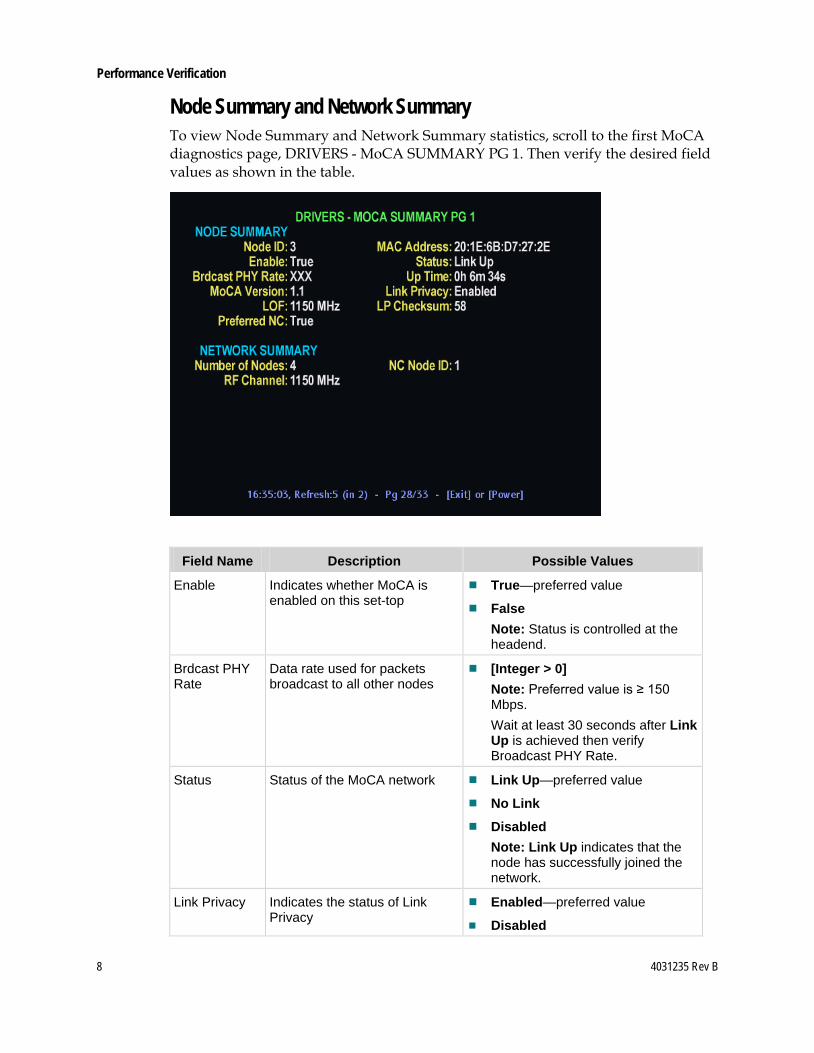
Node Summary and Network Summary To view Node Summary and Network Summary statistics, scroll to the first MoCA diagnostics page, DRIVERS - MoCA SUMMARY PG 1. Then verify the desired field values as shown in the table.
Field Name Description Possible Values
Enable Indicates whether MoCA is enabled on this set-top
True—preferred value
False Note: Status is controlled at the headend.
Brdcast PHY Rate
Data rate used for packets broadcast to all other nodes
[Integer > 0] Note: Preferred value is ≥ 150 Mbps. Wait at least 30 seconds after Link Up is achieved then verify Broadcast PHY Rate.
Status Status of the MoCA network Link Up—preferred value
No Link
Disabled Note: Link Up indicates that the node has successfully joined the network.
Link Privacy Indicates the status of Link Privacy
Enabled—preferred value
Disabled

4031235 Rev B 9
Performance Verification
Field Name Description Possible Values
RF Channel Channel center frequency of the MoCA network (in MHz)
[Range: 1150 – 1500] Important: A changing value indicates that the set-top is hunting for the correct frequency. Note: The RF channel frequency is typically 1150 MHz. If it is not, record the frequency for comparison with other devices on the network.
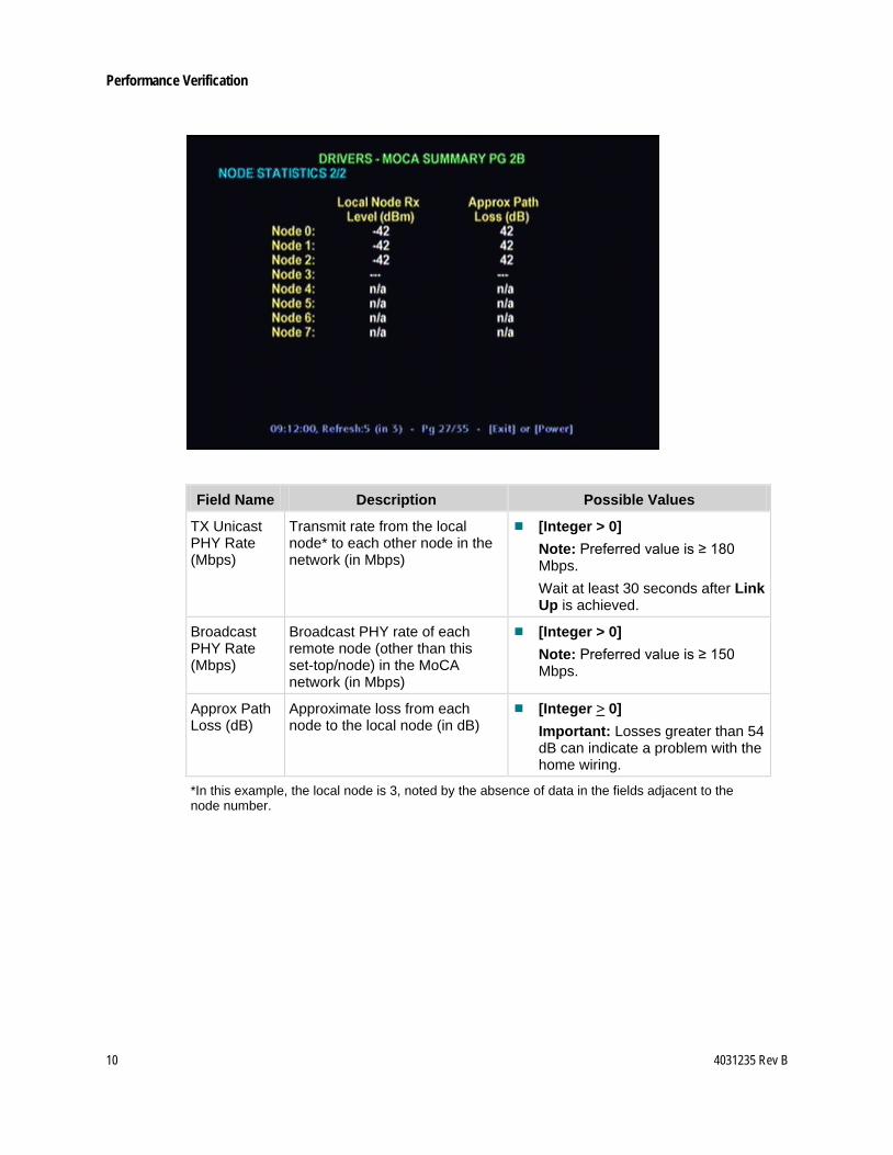
Node Statistics To view Node Statistics, scroll to DRIVERS - MoCA SUMMARY PG 2A and DRIVERS - MoCA SUMMARY PG 2B. Then verify the desired field values as shown in the table.
10 4031235 Rev B
Performance Verification
Field Name Description Possible Values
TX Unicast PHY Rate (Mbps)
Transmit rate from the local node* to each other node in the network (in Mbps)
[Integer > 0] Note: Preferred value is ≥ 180 Mbps. Wait at least 30 seconds after Link Up is achieved.
Broadcast PHY Rate (Mbps)
Broadcast PHY rate of each remote node (other than this set-top/node) in the MoCA network (in Mbps)
[Integer > 0] Note: Preferred value is ≥ 150 Mbps.
Approx Path Loss (dB)
Approximate loss from each node to the local node (in dB)
[Integer > 0] Important: Losses greater than 54 dB can indicate a problem with the home wiring.
*In this example, the local node is 3, noted by the absence of data in the fields adjacent to the node number.
4031235 Rev B 11
Performance Verification
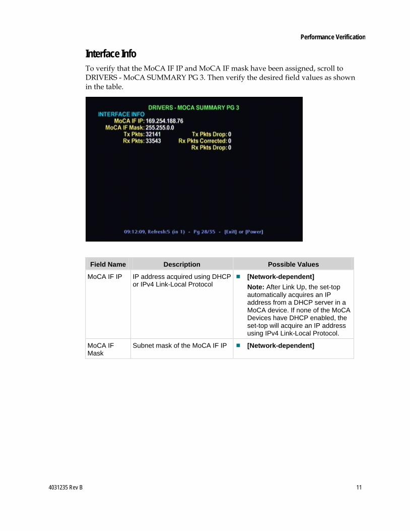
Interface Info To verify that the MoCA IF IP and MoCA IF mask have been assigned, scroll to DRIVERS - MoCA SUMMARY PG 3. Then verify the desired field values as shown in the table.
Field Name Description Possible Values
MoCA IF IP IP address acquired using DHCP or IPv4 Link-Local Protocol
[Network-dependent] Note: After Link Up, the set-top automatically acquires an IP address from a DHCP server in a MoCA device. If none of the MoCA Devices have DHCP enabled, the set-top will acquire an IP address using IPv4 Link-Local Protocol.
MoCA IF Mask
Subnet mask of the MoCA IF IP [Network-dependent]
12 4031235 Rev B
Preventing Interference with Cable Modems
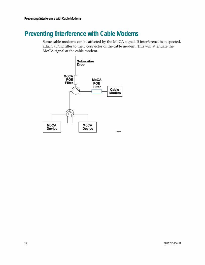
Preventing Interference with Cable Modems Some cable modems can be affected by the MoCA signal. If interference is suspected, attach a POE filter to the F connector of the cable modem. This will attenuate the MoCA signal at the cable modem.
4031235 Rev B 13
Installation Problems
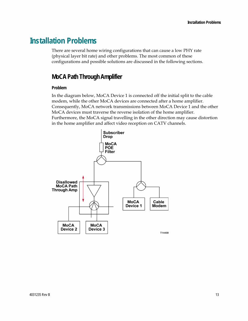
Installation Problems There are several home wiring configurations that can cause a low PHY rate (physical layer bit rate) and other problems. The most common of these configurations and possible solutions are discussed in the following sections.
MoCA Path Through Amplifier Problem In the diagram below, MoCA Device 1 is connected off the initial split to the cable modem, while the other MoCA devices are connected after a home amplifier. Consequently, MoCA network transmissions between MoCA Device 1 and the other MoCA devices must traverse the reverse isolation of the home amplifier. Furthermore, the MoCA signal travelling in the other direction may cause distortion in the home amplifier and affect video reception on CATV channels.
14 4031235 Rev B
Installation Problems
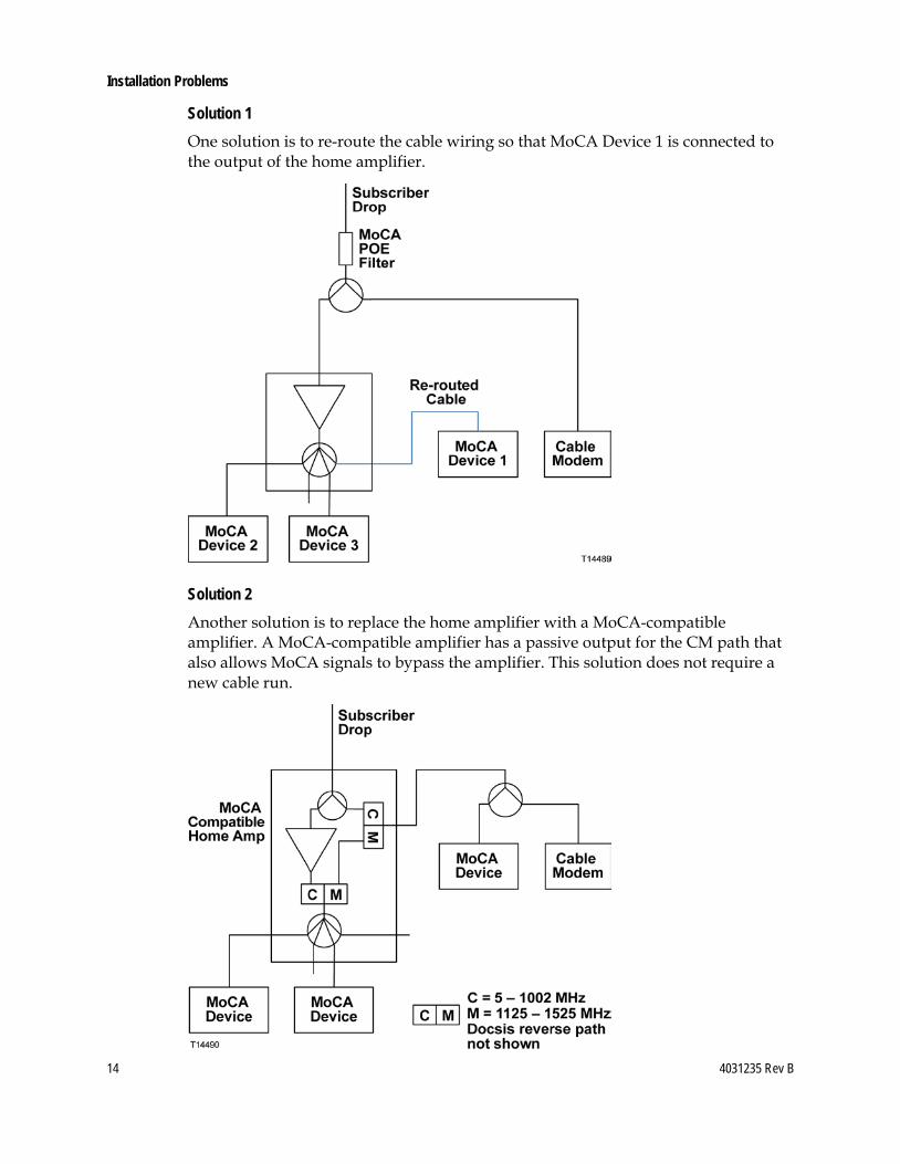
Solution 1 One solution is to re-route the cable wiring so that MoCA Device 1 is connected to the output of the home amplifier.
Solution 2 Another solution is to replace the home amplifier with a MoCA-compatible amplifier. A MoCA-compatible amplifier has a passive output for the CM path that also allows MoCA signals to bypass the amplifier. This solution does not require a new cable run.

4031235 Rev B 15
Installation Problems
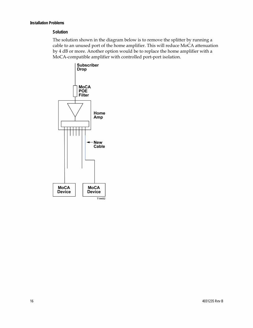
High Loss Problem The diagram below shows a home network that is experiencing high MoCA attenuation due to three factors: the port-port isolation of a home amplifier; long cable runs; and a splitter.
16 4031235 Rev B
Installation Problems
Solution The solution shown in the diagram below is to remove the splitter by running a cable to an unused port of the home amplifier. This will reduce MoCA attenuation by 4 dB or more. Another option would be to replace the home amplifier with a MoCA-compatible amplifier with controlled port-port isolation.

4031235 Rev B 17
Installation Problems
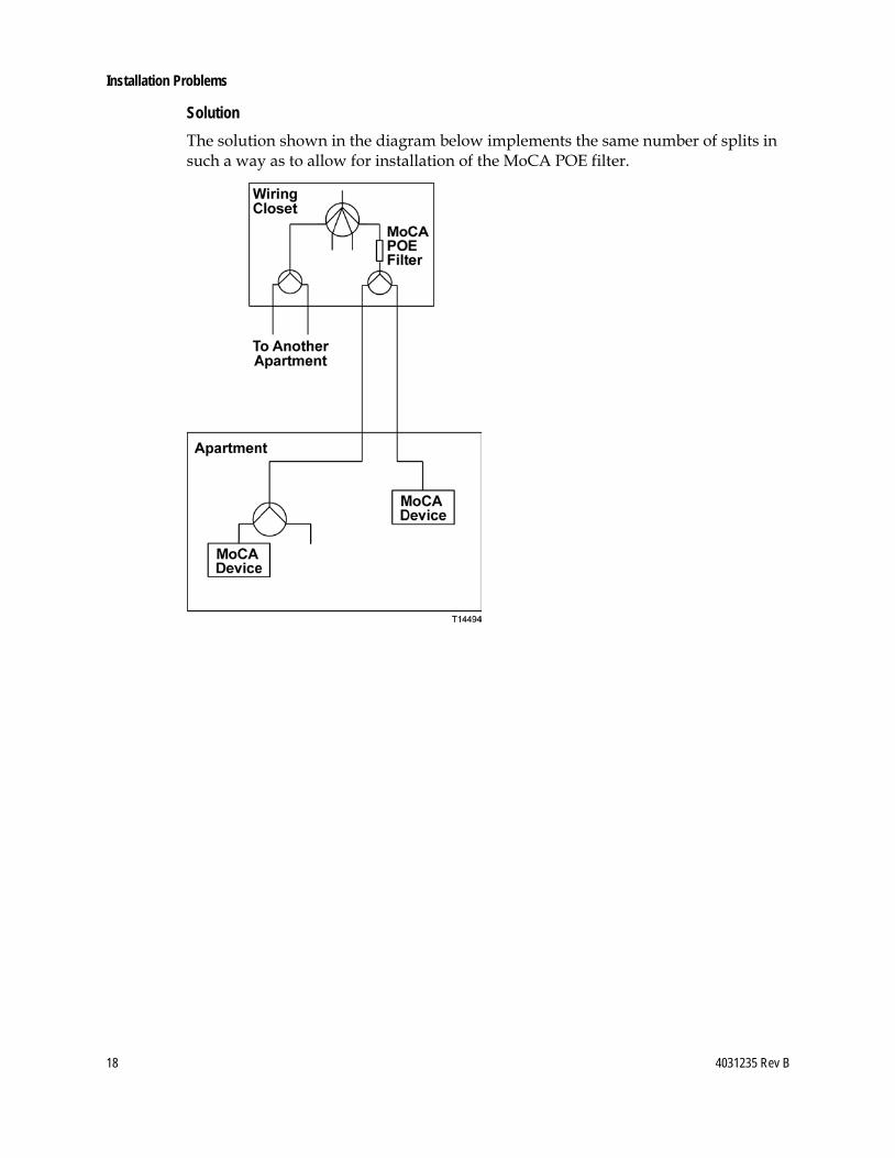
Multi-Dwelling Problem The diagram below shows an apartment wiring closet with multiple apartments fed by the same 8-way splitter. The 8-way splitter prevents installing the MoCA POE filter to isolate apartments.
18 4031235 Rev B
Installation Problems
Solution The solution shown in the diagram below implements the same number of splits in such a way as to allow for installation of the MoCA POE filter.
4031235 Rev B 19
Troubleshooting
Troubleshooting This section contains troubleshooting measures for link loss, high path loss, and low PHY rates.
No Link If there is no MoCA link, check the following: 1 On DRIVERS - MoCA SUMMARY PG 1 (see Node Summary and Network
Summary (on page 8)): Verify that Enable is True. If Enable is False, ask a headend operator to set
the value to True. If Link Privacy is enabled, note the LP checksum value. All nodes must have
the same LP checksum value. Verify that the RF channel frequency is the same for all nodes and that the RF
channel frequency does not change value (hunt). If any of these conditions are not met, there may be a configuration problem on one or more set-tops.
2 At each outlet that feeds a MoCA device, measure the level of the highest channel on the system (e.g. channel 158). If the level is below the specified minimum, correct the home wiring.
3 Check for a home amplifier between MoCA devices (see MoCA Path Through Amplifier (on page 13)). If present, rewire as shown in the solution diagram.
4 Splitters—Check if any splitter feeds a single MoCA device (as opposed to multiple devices). If possible, remove the splitter and connect both devices at the next upstream splitter. Otherwise, verify that the splitter is rated for at least 860 MHz. If not, replace the splitter.
5 Coaxial Surge Arrestors—Check for a coaxial surge arrestor on the cable feeding the set-top, and remove if present.

20 4031235 Rev B
Troubleshooting
Low PHY Rates If the PHY rate is low, check the following: 1 Make sure to wait at least 30 seconds after link is achieved to check the PHY rate. 2 Check the path loss shown on DRIVERS - MoCA SUMMARY PG 2B (see Node
Statistics (on page 9)). If any path losses are greater than 54 dB, connect a level meter to the coaxial cable and measure the level of the highest channel on the system (e.g. channel 158). If the level is below the specified minimum, correct the home wiring.
3 Check for a home amplifier between MoCA devices (see MoCA Path Through Amplifier (on page 13)). If present, implement one of the recommended solutions.
4 Splitters—Check if any splitter feeds a single MoCA device as opposed to multiple devices. If possible, remove the splitter and connect both devices at the next upstream splitter. Otherwise, verify that the splitter is rated for at least 860 MHz. If not, replace the splitter.
5 Long cable runs—Check if any MoCA devices have cable runs longer than 100 feet between the device and the splitter. If possible, reduce the cable length. If RG-59 cable is used, replace with RG-6. Note: For a comparison of the relative signal loss characteristics between RG-59 and RG-6, see Appendix B (on page 25).
6 Coaxial Surge Arrestors—Check for a coaxial surge arrestor on the cable feeding the set-top, and remove if present. Note: See Appendix B (on page 25) for information on PHY rate attenuation.
High Path Loss See Low PHY Rates (on this page), steps 3–6.

4031235 Rev B 21
Appendix A
Appendix A The following tables describe all of the fields and possible values that can appear on the TV when you are reviewing MoCA diagnostic screens. They can be useful for troubleshooting MoCA issues.
DRIVERS - MoCA SUMMARY PG 1
Field Name Description Possible Values
Node ID The local node ID [Range: 0 – N] where N = 7 for MoCA 1.0 and N = 15 for MoCA 1.1
Enable Indicates whether MoCA is enabled on this set-top
True—preferred value
False Note: Status is controlled at the headend.
Brdcast PHY Rate
Data rate used for packets broadcast to all other nodes
[Integer > 0] Note: Preferred value is ≥ 150 Mbps. Wait at least 30 seconds after Link Up is achieved then verify Broadcast PHY Rate.
MoCA Version Version of the MoCA standard supported by the set-top
[Set-top-dependent]
LOF Last Operational Frequency (in MHz). The set-top will automatically default to this frequency after a reboot.
[Integer > 0] Note: This is typically equal to the RF channel.
Preferred NC Determines whether the set-top is configured to be a preferred network coordinator
True—Set-top is configured as a preferred network coordinator
False—Set-top is not configured as a network coordinator Note: Configuring a set-top as a preferred NC means that the set-top (node) has an advantage in the dynamic NC selection process. An NC will still be selected if all the nodes on the network are set to 'False'.
MAC Address MAC address of the MoCA interface
Based on the STB RF MAC on the back of the set-top. Example: If the STB RF MAC of the set-top is 00:1E:6B:D2:4D:4C, the MoCA interface MAC is 20:1E:6B:D2:4D:4C.
22 4031235 Rev B
Appendix A
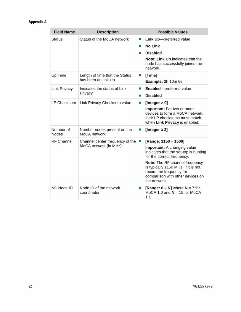
Field Name Description Possible Values
Status Status of the MoCA network Link Up—preferred value
No Link
Disabled Note: Link Up indicates that the node has successfully joined the network.
Up Time Length of time that the Status has been at Link Up
[Time] Example: 3h 10m 6s
Link Privacy Indicates the status of Link Privacy
Enabled—preferred value
Disabled
LP Checksum Link Privacy Checksum value [Integer > 0] Important: For two or more devices to form a MoCA network, their LP checksums must match, when Link Privacy is enabled.
Number of Nodes
Number nodes present on the MoCA network
[Integer ≥ 2]
RF Channel Channel center frequency of the MoCA network (in MHz)
[Range: 1150 – 1500] Important: A changing value indicates that the set-top is hunting for the correct frequency. Note: The RF channel frequency is typically 1150 MHz. If it is not, record the frequency for comparison with other devices on the network.
NC Node ID Node ID of the network coordinator
[Range: 0 – N] where N = 7 for MoCA 1.0 and N = 15 for MoCA 1.1
4031235 Rev B 23
Appendix A
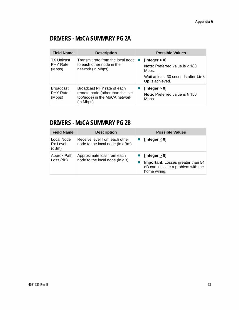
DRIVERS - MoCA SUMMARY PG 2A
Field Name Description Possible Values
TX Unicast PHY Rate (Mbps)
Transmit rate from the local node to each other node in the network (in Mbps)
[Integer > 0] Note: Preferred value is ≥ 180 Mbps. Wait at least 30 seconds after Link Up is achieved.
Broadcast PHY Rate (Mbps)
Broadcast PHY rate of each remote node (other than this set-top/node) in the MoCA network (in Mbps)
[Integer > 0] Note: Preferred value is ≥ 150 Mbps.
DRIVERS - MoCA SUMMARY PG 2B
Field Name Description Possible Values
Local Node Rx Level (dBm)
Receive level from each other node to the local node (in dBm)
[Integer < 0]
Approx Path Loss (dB)
Approximate loss from each node to the local node (in dB)
[Integer > 0]
Important: Losses greater than 54 dB can indicate a problem with the home wiring.
24 4031235 Rev B
Appendix A
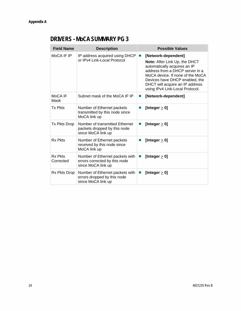
DRIVERS - MoCA SUMMARY PG 3
Field Name Description Possible Values
MoCA IF IP IP address acquired using DHCP or IPv4 Link-Local Protocol
[Network-dependent] Note: After Link Up, the DHCT automatically acquires an IP address from a DHCP server in a MoCA device. If none of the MoCA Devices have DHCP enabled, the DHCT will acquire an IP address using IPv4 Link-Local Protocol.
MoCA IF Mask
Subnet mask of the MoCA IF IP [Network-dependent]
Tx Pkts Number of Ethernet packets transmitted by this node since MoCA link up
[Integer > 0]
Tx Pkts Drop Number of transmitted Ethernet packets dropped by this node since MoCA link up
[Integer > 0]
Rx Pkts Number of Ethernet packets received by this node since MoCA link up
[Integer > 0]
Rx Pkts Corrected
Number of Ethernet packets with errors corrected by this node since MoCA link up
[Integer > 0]
Rx Pkts Drop Number of Ethernet packets with errors dropped by this node since MoCA link up
[Integer > 0]
4031235 Rev B 25
Appendix B
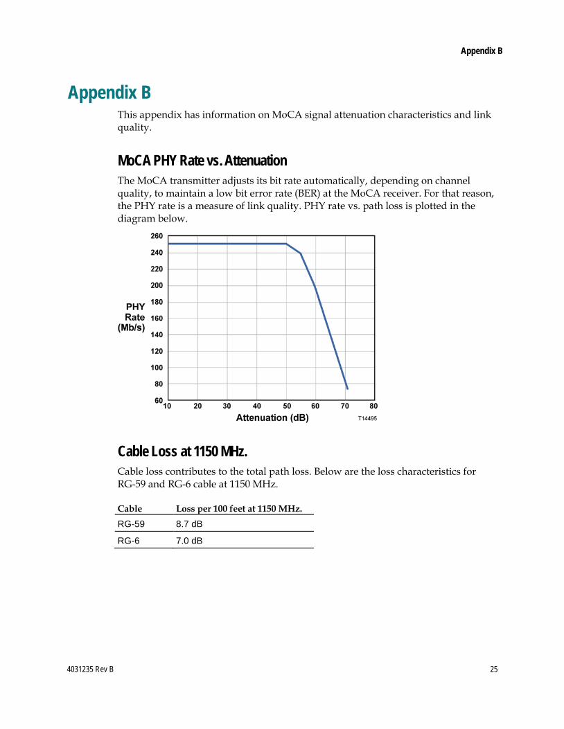
Appendix B This appendix has information on MoCA signal attenuation characteristics and link quality.
MoCA PHY Rate vs. Attenuation The MoCA transmitter adjusts its bit rate automatically, depending on channel quality, to maintain a low bit error rate (BER) at the MoCA receiver. For that reason, the PHY rate is a measure of link quality. PHY rate vs. path loss is plotted in the diagram below.
Cable Loss at 1150 MHz. Cable loss contributes to the total path loss. Below are the loss characteristics for RG-59 and RG-6 cable at 1150 MHz.
Cable Loss per 100 feet at 1150 MHz. RG-59 8.7 dB
RG-6 7.0 dB
For Information
If You Have Questions If you have technical questions, call Cisco Services for assistance. Follow the menu options to speak with a service engineer.
Cisco Systems, Inc. 5030 Sugarloaf Parkway, Box 465447 Lawrenceville, GA 30042
678 277-1120 800 722-2009
www.cisco.com Cisco and the Cisco logo are trademarks or registered trademarks of Cisco and/or its affiliates in the U.S. and other countries. To view a list of cisco trademarks, go to this URL: www.cisco.com/go/trademarks. Third party trademarks mentioned are the property of their respective owners. The use of the word partner does not imply a partnership relationship between Cisco and any other company. (1110R) Product and service availability are subject to change without notice. © 2010, 2012 Cisco and/or its affiliates. All rights reserved. August 2012 Printed in USA Part Number 4031235 Rev B