Embed Size (px)
Citation preview

119956-P1Rev A, 10/98
Instruction Manual
MKS Type 1253EThrottle Valve Controller
Six Shattuck RoadAndover, MA 01810-2449(800) 227-8766 or (978) 975-2350
Fax: (978) 975-0093E-mail: [email protected]
Web site: http://www.mksinst.com

WARRANTYType 1253E Equipment
MKS Instruments, Inc. (MKS) warrants that the equipment described above (the
“equipment”) manufactured by MKS shall be free from defects in materials and
workmanship for a period of one year from date of shipment and will for a period of two
years from the date of shipment, correctly perform all date-related operations, including
without limitation accepting data entry, sequencing, sorting, comparing, and reporting,
regardless of the date the operation is performed or the date involved in the operation,
provided that, if the equipment exchanges data or is otherwise used with equipment,
software, or other products of others, such products of others themselves correctly
perform all date-related operations and store and transmit dates and date-related data
in a format compatible with MKS equipment. THIS WARRANTY IS MKS’ SOLE
WARRANTY CONCERNING DATE-RELATED OPERATIONS.
For the period commencing with the date of shipment of this equipment and ending one
year later in the case of defects in materials and workmanship, but two years later in the
case of failure to comply with the date-related operations warranty, MKS will, at its
option, either repair or replace any part which is defective in materials or workmanship
or with respect to the date-related operations warranty without charge to the purchaser.
The foregoing shall constitute the exclusive and sole remedy of the purchaser for any
breach by MKS of this warranty.
The purchaser, before returning any equipment covered by this warranty, which is
asserted to be defective by the purchaser, shall make specific written arrangements
with respect to the responsibility for shipping the equipment and handling any other
incidental charges with the MKS sales representative or distributor from which the
equipment was purchased or, in the case of a direct purchase from MKS, with the MKShome office in Andover, Massachusetts, USA.
This warranty does not apply to any equipment which has not been installed and used
in accordance with the specifications recommended by MKS for the proper and normal
use of the equipment. MKS shall not be liable under any circumstances for indirect,
special, consequential, or incidental damages in connection with, or arising out of, the
sale, performance, or use of the equipment covered by this warranty.
MKS recommends that all MKS pressure and flow products be calibrated periodically
(typically every 6 to 12 months) to ensure accurate readings. When a product is
returned to MKS for this periodic re-calibration it is considered normal preventative
maintenance not covered by any warranty.
THIS WARRANTY IS IN LIEU OF ALL OTHER RELEVANT WARRANTIES,
EXPRESSED OR IMPLIED, INCLUDING THE IMPLIED WARRANTY OF
MERCHANTABILITY AND THE IMPLIED WARRANTY OF FITNESS FOR A
PARTICULAR PURPOSE, AND ANY WARRANTY AGAINST INFRINGEMENT OF
ANY PATENT.
11-98 119956-P1

119956-P1Rev A, 10/97
MKS Type 1253EThrottle Valve Controller

Copyright © 1997 by MKS Instruments, Inc.
All rights reserved. No part of this work may be reproduced or transmitted in any form or byany means, electronic or mechanical, including photocopying and recording, or by anyinformation storage or retrieval system, except as may be expressly permitted in writing by MKSInstruments, Inc.
Baratron is a registered trademark and Cluster Gauge™ is a trademark of MKS Instruments,Inc., Andover, MA
This manual is for firmware/software version: 1.1x
Please Note:MKS Instruments provides these documents as the latest version for the revision indicated.The material is subject to change without notice, and should be verified if used in a criticalapplication.
Table of Contents
iii
Table of Contents
Safety Information.................................................................................................................. 1
Symbols Used in This Instruction Manual.................................................................. 1
Symbols Found on the Unit ....................................................................................... 2
Safety Procedures and Precautions ............................................................................. 3
Chapter One: General Information......................................................................................... 5
Introduction ............................................................................................................... 5
How This Manual is Organized.................................................................................. 6
Customer Support ...................................................................................................... 6
Chapter Two: Installation ...................................................................................................... 7
How To Unpack the Type 1253 Unit.......................................................................... 7
Unpacking Checklist ..................................................................................... 7
Interface Cables ......................................................................................................... 8
System Interface Cables ................................................................................ 8
Generic Shielded Cables................................................................................ 9
Setup ......................................................................................................................... 10
Dimensions ................................................................................................... 10
Power Requirements...................................................................................... 12
System Considerations .................................................................................. 12
System Design .............................................................................................. 12
Mounting Instructions ................................................................................... 12
Grounding ..................................................................................................... 13
Connectors and Cables............................................................................................... 14
Valve Connector (J3)..................................................................................... 14
Power Connector (J2) .................................................................................... 15
Input Connector (J1)...................................................................................... 16
RS-232 Communications Cable..................................................................... 18
Chapter Three: Overview....................................................................................................... 19
General Information................................................................................................... 19
Table of Contents
iv
External Connectors and Controls ..............................................................................21
Power ON LED .............................................................................................21
Valve Connector ............................................................................................21
Valve Open LED ...........................................................................................21
Manual Valve Switch.....................................................................................21
Valve Closed LED.........................................................................................21
Power Connector ...........................................................................................22
Input Connector .............................................................................................22
Internal Controls ........................................................................................................23
Dipswitch Bank .............................................................................................23
Power-Down Constants ..............................................................................................26
Chapter Four: Operation ........................................................................................................27
General Information ...................................................................................................27
RS-232 Communication Parameters ...........................................................................28
How To Change the Dipswitch Settings.........................................................29
RS-232 Operating Commands ....................................................................................30
RS-232 Requests and Response Messages ..................................................................31
How To Learn the Valve ............................................................................................32
How To Reset the 1253 Controller .............................................................................33
How To Tune the Controller.......................................................................................34
How To Calibrate the Controller ................................................................................35
How To Calibrate the Analog Set Point .........................................................35
How To Calibrate the Transducer Range........................................................36
How To Learn the Number of Valve Steps.....................................................37
How To Connect the Controller to the Type 146 Cluster Gauge™..............................38
Chapter Five: Maintenance and Troubleshooting....................................................................39
General Information ...................................................................................................39
Maintenance...............................................................................................................39
Troubleshooting .........................................................................................................39
Valve Slippage Signal....................................................................................39
Appendix A: Product Specifications.......................................................................................41
Appendix B: Model Code Explanation...................................................................................43

Table of Contents
v
Model Code............................................................................................................... 43
Index...................................................................................................................................... 45

Table of Contents
vi
List of Figures and Tables
vii
List of Figures and Tables
Figures
Figure 1: Front Panel Dimensions ......................................................................................... 10
Figure 2: Side Panel Dimensions........................................................................................... 10
Figure 3: Top Panel Dimensions............................................................................................ 11
Figure 4: Returned Leads Tied to System Ground ................................................................. 13
Figure 5: Null Modem RS-232 Communication Cable .......................................................... 18
Figure 6: Example Piping and Cable Connections for the 1253 Controller............................. 20
Figure 7: Front Panel of the 1253 Controller ......................................................................... 21
Figure 8: Location of the Dipswitch Bank on the CPU Board ................................................ 23
Tables
Table 1: Definition of Symbols Found on the Unit .....................................................................2
Table 2: System Interface Cables................................................................................................8
Table 3: Valve Connector (J3) Pinout .......................................................................................14
Table 4: Power Connector (P2) Pinout......................................................................................15
Table 5: Input Connector (J1) Pinout ........................................................................................16
Table 6: Dipswitch Functions and Settings ...............................................................................24
Table 7: Initial RS-232 Communication Parameters .................................................................28
Table 8: RS-232 Operating Commands ....................................................................................30
Table 9: RS-232 Request and Response Messages....................................................................31
Table 10: Operating Values Established by the “B” Command .................................................33

List of Figures and Tables
viii
Safety Information
1
Safety Information
Symbols Used in This Instruction Manual
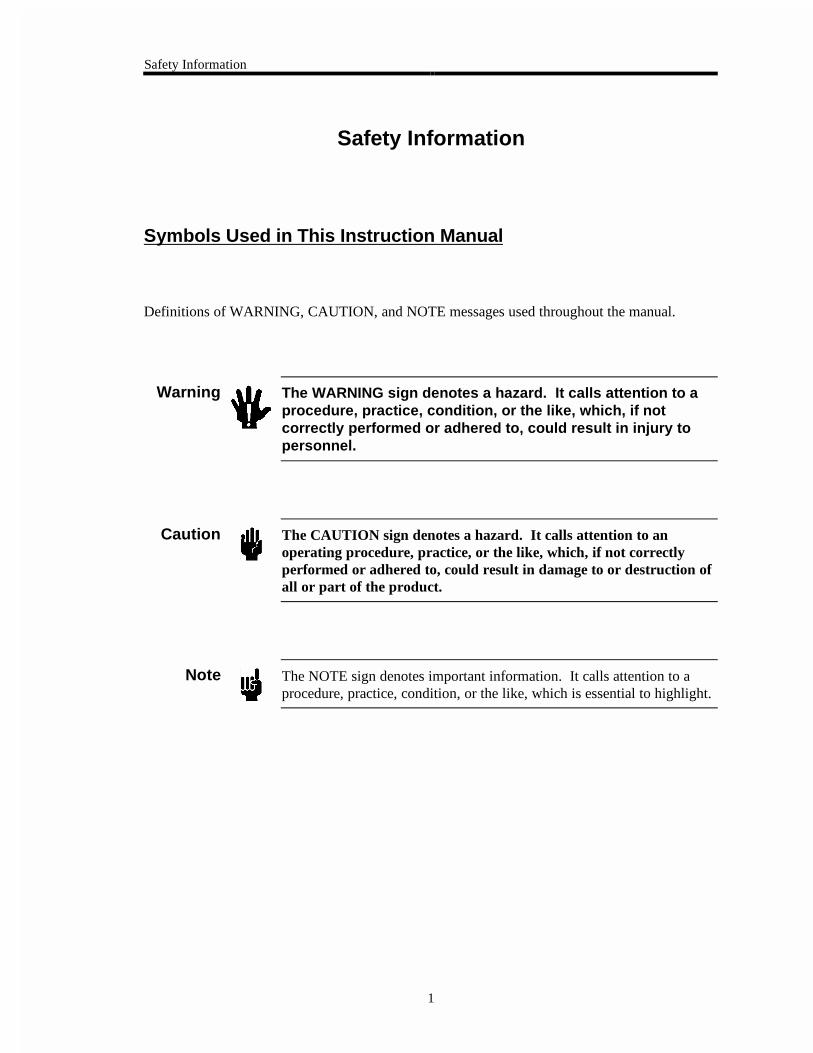
Definitions of WARNING, CAUTION, and NOTE messages used throughout the manual.
Warning The WARNING sign denotes a hazard. It calls attention to aprocedure, practice, condition, or the like, which, if notcorrectly performed or adhered to, could result in injury topersonnel.
Caution The CAUTION sign denotes a hazard. It calls attention to anoperating procedure, practice, or the like, which, if not correctlyperformed or adhered to, could result in damage to or destruction ofall or part of the product.
Note The NOTE sign denotes important information. It calls attention to aprocedure, practice, condition, or the like, which is essential to highlight.
Safety Information
2
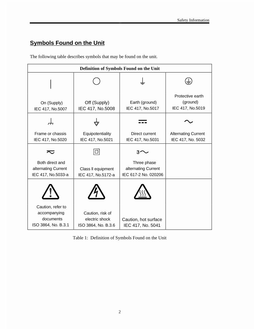
Symbols Found on the Unit
The following table describes symbols that may be found on the unit.
Definition of Symbols Found on the Unit
|
On (Supply) IEC 417, No.5007
Off (Supply) IEC 417, No.5008
Earth (ground) IEC 417, No.5017
Protective earth (ground)
IEC 417, No.5019
Frame or chassis IEC 417, No.5020
Equipotentiality IEC 417, No.5021
Direct current IEC 417, No.5031
Alternating Current IEC 417, No. 5032
Both direct and alternating Current
IEC 417, No.5033-aClass ll equipment
IEC 417, No.5172-a
Three phase alternating Current
IEC 617-2 No. 020206
Caution, refer to accompanying
documents ISO 3864, No. B.3.1
Caution, risk of electric shock
ISO 3864, No. B.3.6Caution, hot surface IEC 417, No. 5041
Table 1: Definition of Symbols Found on the Unit
Safety Information
3
Safety Procedures and Precautions
The following general safety precautions must be observed during all phases of operation of thisinstrument. Failure to comply with these precautions or with specific warnings elsewhere inthis manual violates safety standards of intended use of the instrument and may impair theprotection provided by the equipment. MKS Instruments, Inc. assumes no liability for thecustomer’s failure to comply with these requirements.
DO NOT SUBSTITUTE PARTS OR MODIFY INSTRUMENT
Do not install substitute parts or perform any unauthorized modification to the instrument.Return the instrument to an MKS Calibration and Service Center for service and repair to ensurethat all safety features are maintained.
SERVICE BY QUALIFIED PERSONNEL ONLY
Operating personnel must not remove instrument covers. Component replacement and internaladjustments must be made by qualified service personnel only.
DANGER ARISING FROM LOSS OF GROUND
Upon loss of the protective-ground connection, all accessible conductive parts (including knobsand controls that may appear to be insulating) can render an electrical shock.
GROUND AND USE PROPER ELECTRICAL FITTINGS
Dangerous voltages are contained within this instrument. All electrical fittings and cables mustbe of the type specified, and in good condition. All electrical fittings must be properly connectedand grounded.
USE THE PROPER POWER SOURCE
This product is intended to operate from a power source that does not apply more voltagebetween the supply conductors, or between either of the supply conductors and ground, than thatspecified in the manual.
DO NOT OPERATE IN EXPLOSIVE ATMOSPHERES
To avoid explosion, do not operate this product in an explosive environment unless it has beenspecifically certified for such operation.

Safety Information
4
Chapter One: General Information Introduction
5
Chapter One: General Information
Introduction
The Type 1253E “Smart” Throttle Valve Controller is designed for use in downstream pressurecontrol applications with the MKS Type 253 Throttle Valve. The 1253 unit includes amicroprocessor, RS-232 communication connections, and driver circuits. The driver circuitseliminate the need for a separate controller box.
The 1253 controller contains a digital pressure/position control algorithm that directs the 253valve to the proper position for either pressure or position control. The pressure or position setpoint may be an external voltage applied to the input connector, or sent as a digital RS-232message. The 1253 unit reads the pressure signal used for control applications directly from apressure transducer.
Power for the 1253 unit can be a single DC supply of +15 to +30 Volts. You can use a+15 VDC, +24 VDC, or +28 VDC supply. The unit requires approximately 5 Watts of power.
Note Use a ±15 V supply to power the 1253 unit if you plan to power atransducer from the 1253 unit.
When the controller is turned off, or experiences an unexpected power loss, all calibrationconstants and the last valve position are saved in non-volatile memory. Therefore, when yourepower the unit, it will be calibrated and ready for operation.
A switch on the front of the controller allows for off-line operation of the valve fortroubleshooting. Dipswitches inside the controller allow you to configure the controller’soperating parameters; refer to Internal Controls, page 23, for more information.
How This Manual is Organized Chapter One: General Information
6
How This Manual is Organized
This manual is designed to provide instructions on how to set up, install, and operate a Type1253 unit.
Before installing your Type 1253 unit in a system and/or operating it, carefully read andfamiliarize yourself with all precautionary notes in the Safety Messages and Proceduressection at the front of this manual. In addition, observe and obey all WARNING andCAUTION notes provided throughout the manual.
Chapter One, General Information, (this chapter) introduces the product and describes theorganization of the manual.
Chapter Two, Installation, explains the environmental requirements and describes how to mountthe instrument in your system.
Chapter Three, Overview, gives a brief description of the instrument and its functionality.
Chapter Four, Operation, describes how to use the instrument and explains all the functions andfeatures.
Chapter Five, Maintennace and Troubleshooting, describes basic maintenance procedures andtroubleshooting procedures should the 1253 unit malfunction.
Appendix A, Product Specifications, lists the specifications of the instrument.
Appendix B, Model Code Explanation, describes the instrument’s model code.
Customer Support
Standard maintenance and repair services are available at all of our regional MKS Calibrationand Service Centers, listed on the back cover. In addition, MKS accepts the instruments of othermanufacturers for recalibration using the Primary and Transfer Standard calibration equipmentlocated at all of our regional service centers. Should any difficulties arise in the use of your Type1253 instrument, or to obtain information about companion products MKS offers, contact anyauthorized MKS Calibration and Service Center. If it is necessary to return the instrument toMKS, please obtain an ERA Number (Equipment Return Authorization Number) from the MKSCalibration and Service Center before shipping. The ERA Number expedites handling andensures proper servicing of your instrument.
Please refer to the inside of the back cover of this manual for a list of MKS Calibration andService Centers.
Warning All returns to MKS Instruments must be free of harmful,corrosive, radioactive, or toxic materials.
Chapter Two: Installation How To Unpack the Type 1253 Unit
7
Chapter Two: Installation
How To Unpack the Type 1253 Unit
MKS has carefully packed the Type 1253 unit so that it will reach you in perfect operating order.Upon receiving the unit, however, you should check for defects, cracks, broken connectors, etc.,to be certain that damage has not occurred during shipment.
Note Do not discard any packing materials until you have completed yourinspection and are sure the unit arrived safely.
If you find any damage, notify your carrier and MKS immediately. If it is necessary to return theunit to MKS, obtain an ERA Number (Equipment Return Authorization Number) from the MKSService Center before shipping. Please refer to the inside of the back cover of this manual for alist of MKS Calibration and Service Centers.
Caution Only qualified individuals should perform the installation and anyuser adjustments. They must comply with all the necessary ESD andhandling precautions while installing and adjusting the instrument.Proper handling is essential when working with all highly sensitiveprecision electronic instruments.
Unpacking Checklist
Standard Equipment:
• Type 1253 Unit
• Type 1253 Instruction Manual (this book)
Optional Equipment:
• Electrical Connector Accessory Kit:1253E-K1
• Power Supply:
260 PS-1 (± 15 V, 1.5 Amps)260 PS-3 (± 15 V, 3.2 Amps)
• PT-1A Portable RS-232 Terminal
• Interface Cables (refer to Table 2, page 8)
Interface Cables Chapter Two: Installation
8
Interface Cables
As of January 1, 1996, most products shipped to the European Community must comply with theEMC Directive 89/336/EEC, which covers radio frequency emissions and immunity tests. Inaddition, as of January 1, 1997, some products shipped to the European Community must alsocomply with the Product Safety Directive 92/59/EEC and Low-Voltage Directive 73/23/EEC,which cover general safety practices for design and workmanship. MKS products that meetthese requirements are identified by application of the CE mark.
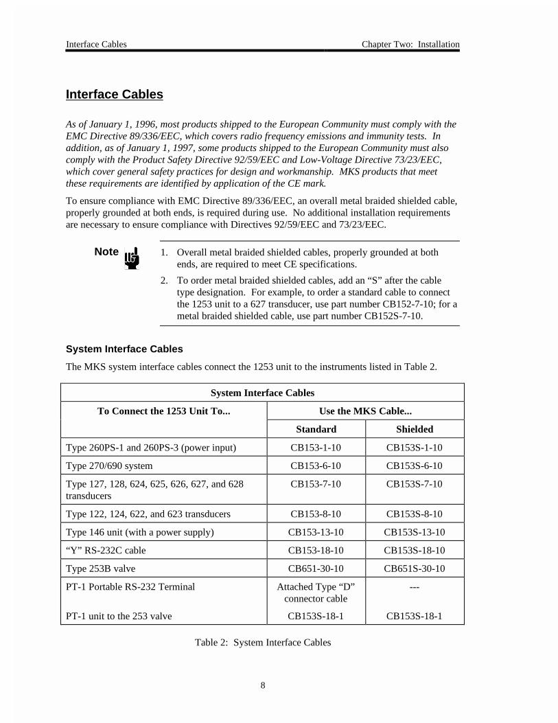
To ensure compliance with EMC Directive 89/336/EEC, an overall metal braided shielded cable,properly grounded at both ends, is required during use. No additional installation requirementsare necessary to ensure compliance with Directives 92/59/EEC and 73/23/EEC.
Note 1. Overall metal braided shielded cables, properly grounded at bothends, are required to meet CE specifications.
2. To order metal braided shielded cables, add an “S” after the cabletype designation. For example, to order a standard cable to connectthe 1253 unit to a 627 transducer, use part number CB152-7-10; for ametal braided shielded cable, use part number CB152S-7-10.
System Interface Cables
The MKS system interface cables connect the 1253 unit to the instruments listed in Table 2.
System Interface Cables
To Connect the 1253 Unit To... Use the MKS Cable...
Standard Shielded
Type 260PS-1 and 260PS-3 (power input) CB153-1-10 CB153S-1-10
Type 270/690 system CB153-6-10 CB153S-6-10
Type 127, 128, 624, 625, 626, 627, and 628transducers
CB153-7-10 CB153S-7-10
Type 122, 124, 622, and 623 transducers CB153-8-10 CB153S-8-10
Type 146 unit (with a power supply) CB153-13-10 CB153S-13-10
“Y” RS-232C cable CB153-18-10 CB153S-18-10
Type 253B valve CB651-30-10 CB651S-30-10
PT-1 Portable RS-232 Terminal
PT-1 unit to the 253 valve
Attached Type “D”connector cable
CB153S-18-1
---
CB153S-18-1
Table 2: System Interface Cables
Chapter Two: Installation Interface Cables
9
Generic Shielded Cables
MKS offers a full line of cables for all MKS equipment. Should you choose to manufacture yourown cables, follow the guidelines listed below:
1. The cable must have an overall metal braided shield, covering all wires. Neitheraluminum foil nor spiral shielding will be as effective; using either may nullifyregulatory compliance.
2. The connectors must have a metal case which has direct contact to the cable’s shield onthe whole circumference of the cable. The inductance of a flying lead or wire from theshield to the connector will seriously degrade the shield’s effectiveness. The shieldshould be grounded to the connector before its internal wires exit.
3. With very few exceptions, the connector(s) must make good contact to the device’s case(ground). “Good contact” is about 0.01 ohms; and the ground should surround all wires.Contact to ground at just one point may not suffice.
4. For shielded cables with flying leads at one or both ends; it is important at each such end,to ground the shield before the wires exit. Make this ground with absolute minimumlength. (A ¼ inch piece of #22 wire may be undesirably long since it has approximately5 nH of inductance, equivalent to 31 ohms at 1000 MHz). After picking up the braid’sground, keep wires and braid flat against the case. With very few exceptions, groundedmetal covers are not required over terminal strips. If one is required, it will be stated inthe Declaration of Conformity or in the instruction manual.
5. In selecting the appropriate type and wire size for cables, consider:
A. The voltage ratings;
B. The cumulative I2R heating of all the conductors (keep them safely cool);
C. The IR drop of the conductors, so that adequate power or signal voltage gets to thedevice;
D. The capacitance and inductance of cables which are handling fast signals, (such asdata lines or stepper motor drive cables); and
E. That some cables may need internal shielding from specific wires to others; pleasesee the instruction manual for details regarding this matter.
Setup Chapter Two: Installation
10
Setup
Dimensions
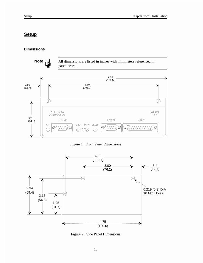
Note All dimensions are listed in inches with millimeters referenced inparentheses.
7.50(190.5)
0.50(12.7)
6.50(165.1)
2.16(54.8)
Figure 1: Front Panel Dimensions
0.219 (5.3) DIA10 Mtg Holes
4.75(120.6)
1.25(31.7)
2.16(54.8)
2.34(59.4)
0.50(12.7)
3.00(76.2)
4.06(103.1)
Figure 2: Side Panel Dimensions
Chapter Two: Installation Setup
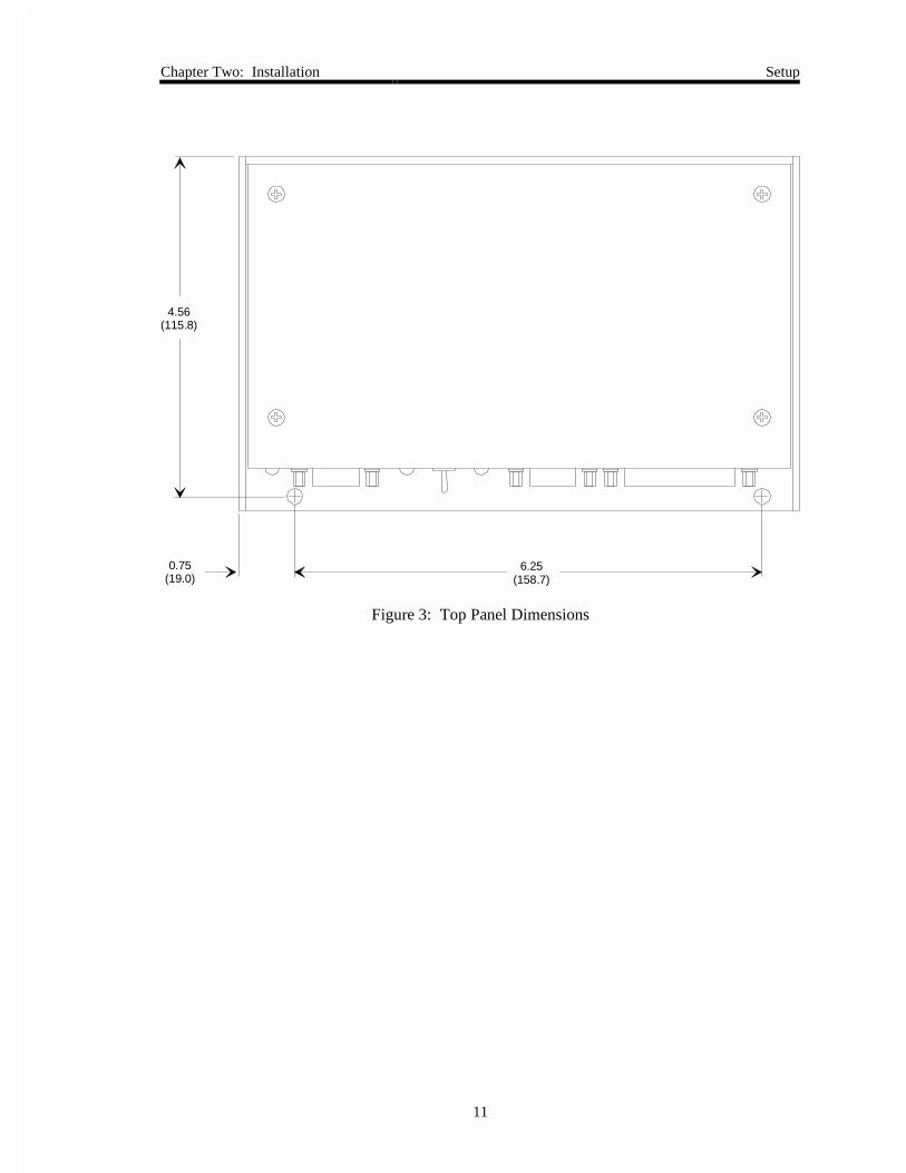
11
4.56(115.8)
0.75(19.0)
6.25(158.7)
Figure 3: Top Panel Dimensions
Setup Chapter Two: Installation
12
Power Requirements
Power for the 1253 unit can be a single DC supply of +15 to +30 Volts. You can use a+15 VDC, +24 VDC, or +28 VDC supply. The unit requires approximately 5 Watts of power.
Note Use a ±15 V supply to power the 1253 unit if you plan to power atransducer from the 1253 unit.
System Considerations
For best pressure control, locate the pressure transducer and exhaust valve as close as practical tothe process chamber. This minimizes the time constants associated with these items. Use tubingthat is less than 6 inches long and no less than ¼ inch in diameter to connect the transducer andchamber. If the distance must exceed 6 inches, use larger diameter tubing to compensate forconductance losses.
System Design
The 1253 unit controls an external 253 valve (not included). This valve can be sized for a widevariety of applications. The size of the valve is dictated by the size of the vacuum exhaust lineand the range of conductance necessary for the pressure and flow rates being used.
Mounting Instructions
The 1253 controller can be mounted in any position. For optimum performance, mount thepower supply and 1253 unit near the valve. This reduces the length of cable necessary to connectthe valve to the unit and thereby reduces the amount of voltage loss in the valve drive cables.Refer to the 253 Instruction Manual for directions on mounting the valve.
Chapter Two: Installation Setup
13
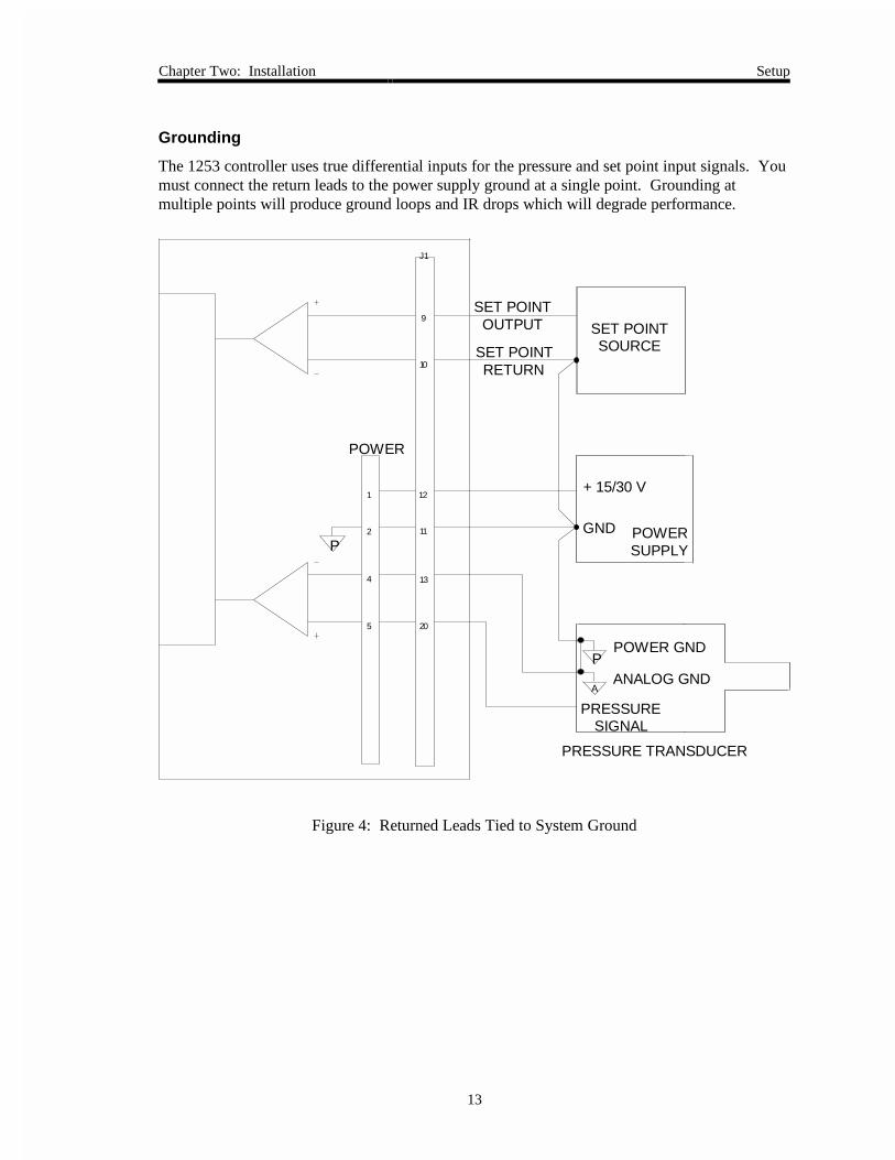
Grounding
The 1253 controller uses true differential inputs for the pressure and set point input signals. Youmust connect the return leads to the power supply ground at a single point. Grounding atmultiple points will produce ground loops and IR drops which will degrade performance.
J1
10
9
P
1 12
2
4
5
11
13
20
P
A
POWER
PRESSURE TRANSDUCER
SET POINTOUTPUT
SET POINTRETURN
POWER GND
ANALOG GND
PRESSURESIGNAL
SET POINTSOURCE
+ 15/30 V
GND POWERSUPPLY
Figure 4: Returned Leads Tied to System Ground
Connectors and Cables Chapter Two: Installation
14
Connectors and Cables
There are three connectors located on the front panel of the 1253 controller (refer to Figure 7,page 21). The controller can be configured in variety of ways; the system interface cablessupplied by MKS are listed in Table 2, page 8.
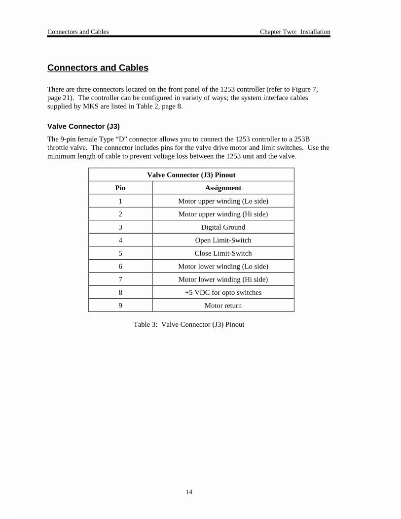
Valve Connector (J3)
The 9-pin female Type “D” connector allows you to connect the 1253 controller to a 253Bthrottle valve. The connector includes pins for the valve drive motor and limit switches. Use theminimum length of cable to prevent voltage loss between the 1253 unit and the valve.
Valve Connector (J3) Pinout
Pin Assignment
1 Motor upper winding (Lo side)
2 Motor upper winding (Hi side)
3 Digital Ground
4 Open Limit-Switch
5 Close Limit-Switch
6 Motor lower winding (Lo side)
7 Motor lower winding (Hi side)
8 +5 VDC for opto switches
9 Motor return
Table 3: Valve Connector (J3) Pinout
Chapter Two: Installation Connectors and Cables
15
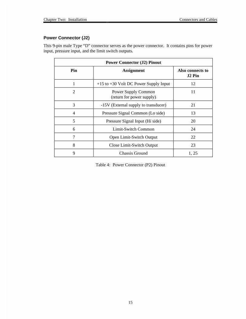
Power Connector (J2)
This 9-pin male Type “D” connector serves as the power connector. It contains pins for powerinput, pressure input, and the limit switch outputs.
Power Connector (J2) Pinout
Pin Assignment Also connects toJ2 Pin
1 +15 to +30 Volt DC Power Supply Input 12
2 Power Supply Common(return for power supply)
11
3 -15V (External supply to transducer) 21
4 Pressure Signal Common (Lo side) 13
5 Pressure Signal Input (Hi side) 20
6 Limit-Switch Common 24
7 Open Limit-Switch Output 22
8 Close Limit-Switch Output 23
9 Chassis Ground 1, 25
Table 4: Power Connector (P2) Pinout
Connectors and Cables Chapter Two: Installation
16
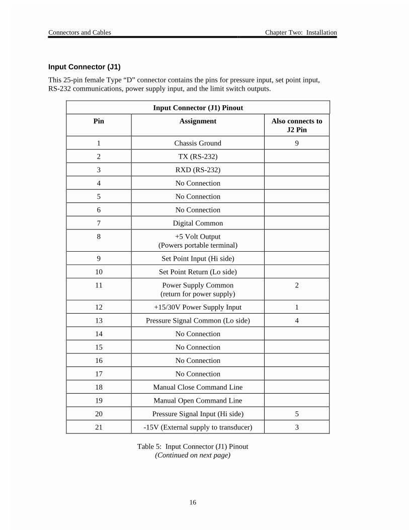
Input Connector (J1)
This 25-pin female Type “D” connector contains the pins for pressure input, set point input,RS-232 communications, power supply input, and the limit switch outputs.
Input Connector (J1) Pinout
Pin Assignment Also connects toJ2 Pin
1 Chassis Ground 9
2 TX (RS-232)
3 RXD (RS-232)
4 No Connection
5 No Connection
6 No Connection
7 Digital Common
8 +5 Volt Output(Powers portable terminal)
9 Set Point Input (Hi side)
10 Set Point Return (Lo side)
11 Power Supply Common(return for power supply)
2
12 +15/30V Power Supply Input 1
13 Pressure Signal Common (Lo side) 4
14 No Connection
15 No Connection
16 No Connection
17 No Connection
18 Manual Close Command Line
19 Manual Open Command Line
20 Pressure Signal Input (Hi side) 5
21 -15V (External supply to transducer) 3
Table 5: Input Connector (J1) Pinout(Continued on next page)
Chapter Two: Installation Connectors and Cables
17
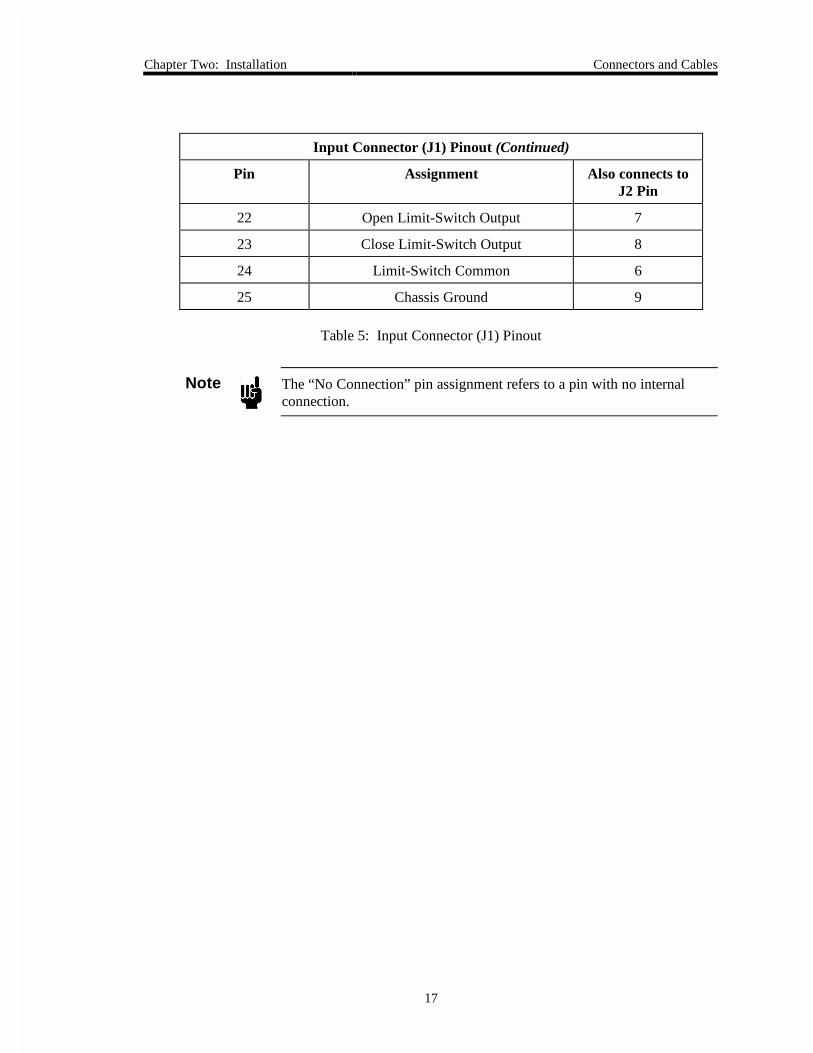
Input Connector (J1) Pinout (Continued)
Pin Assignment Also connects toJ2 Pin
22 Open Limit-Switch Output 7
23 Close Limit-Switch Output 8
24 Limit-Switch Common 6
25 Chassis Ground 9
Table 5: Input Connector (J1) Pinout
Note The “No Connection” pin assignment refers to a pin with no internalconnection.
Connectors and Cables Chapter Two: Installation
18
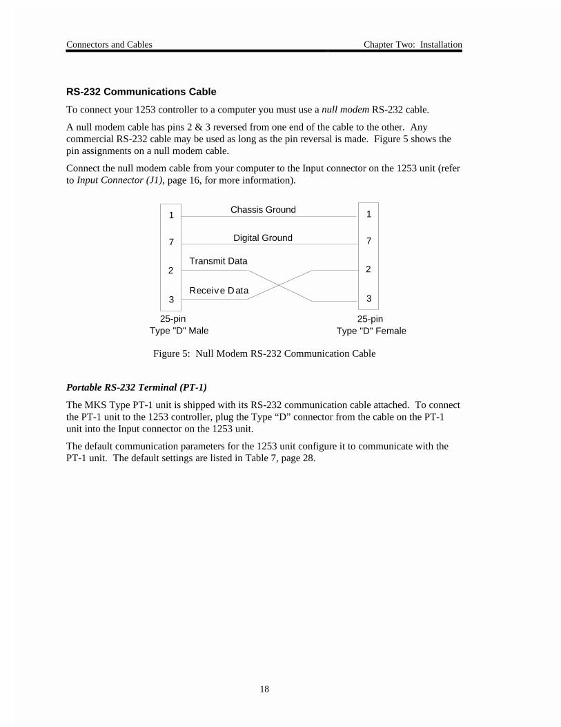
RS-232 Communications Cable
To connect your 1253 controller to a computer you must use a null modem RS-232 cable.
A null modem cable has pins 2 & 3 reversed from one end of the cable to the other. Anycommercial RS-232 cable may be used as long as the pin reversal is made. Figure 5 shows thepin assignments on a null modem cable.
Connect the null modem cable from your computer to the Input connector on the 1253 unit (referto Input Connector (J1), page 16, for more information).
1
7
2
3
1
7
2
3
Chassis Ground
Digital Ground
Transmit Data
Receive Data
25-pin Type "D" Male
25-pin Type "D" Female
Figure 5: Null Modem RS-232 Communication Cable
Portable RS-232 Terminal (PT-1)
The MKS Type PT-1 unit is shipped with its RS-232 communication cable attached. To connectthe PT-1 unit to the 1253 controller, plug the Type “D” connector from the cable on the PT-1unit into the Input connector on the 1253 unit.
The default communication parameters for the 1253 unit configure it to communicate with thePT-1 unit. The default settings are listed in Table 7, page 28.
Chapter Three: Overview General Information
19
Chapter Three: Overview
General Information
The 1253 controller can accept a set point signal from either an external (analog) voltage sourceor a RS-232 (digital) source. In either case, the Input connector acts as the interface.
The 1253 unit can accept the pressure signal through either the Input or Power connector. Whenthe pressure signal is received through the Power connector, a split power supply cable can beused to interface the pressure transducer and the controller through the Power connector. Thisleaves the Input connector empty to interface with the RS-232 port on an external computer.
The pressure and set point inputs to the 1253 controller are both differential inputs that are notinternally referenced to ground. Tie the returns to the system ground at a single point (refer toGrounding, page 13, for more information).
The 1253 unit requires +15 to +30 Volts. If you need to power a pressure transducer through the1253 unit, you must supply ±15 VDC to the 1253 unit. The controller uses the +15 V and sendsthe ±15 V on to the pressure transducer through the Input connector. Figure 6, page 20, showsthe ±15 Volts being supplied from an MKS Type 260 Power Supply through the appropriatecable to the 1253 unit. The pressure transducer power and pressure signal connections are madethrough the Input connector.
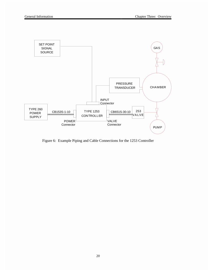
General Information Chapter Three: Overview
20
CHAMBER
GAS
PUMP
SET POINT SIGNAL SOURCE
TYPE 260 POWER SUPPLY
CB153S-1-10CONTROLLER
TYPE 1253 253VA LVE
CB651S-30-10
PRESSURETRANSDUCER
INPUTConnector
VALVEConnector
POWERConnector
Figure 6: Example Piping and Cable Connections for the 1253 Controller
Chapter Three: Overview External Connectors and Controls
21
External Connectors and Controls
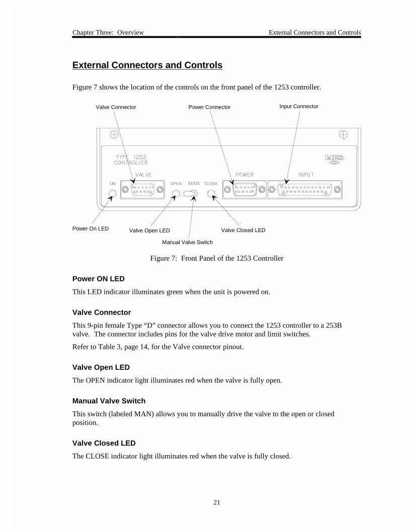
Figure 7 shows the location of the controls on the front panel of the 1253 controller.
Power On LED Valve Open LED
Manual Valve Switch
Valve Closed LED
Valve Connector Power Connector Input Connector
Figure 7: Front Panel of the 1253 Controller
Power ON LED
This LED indicator illuminates green when the unit is powered on.
Valve Connector
This 9-pin female Type “D” connector allows you to connect the 1253 controller to a 253Bvalve. The connector includes pins for the valve drive motor and limit switches.
Refer to Table 3, page 14, for the Valve connector pinout.
Valve Open LED
The OPEN indicator light illuminates red when the valve is fully open.
Manual Valve Switch
This switch (labeled MAN) allows you to manually drive the valve to the open or closedposition.
Valve Closed LED
The CLOSE indicator light illuminates red when the valve is fully closed.

External Connectors and Controls Chapter Three: Overview
22
Power Connector
This 9-pin male Type “D” connector serves as the power connector. It contains pins for powerinput, pressure input, and the limit switch outputs.
Refer to Table 4, page 15, for the Power connector pinout.
Input Connector
This 25-pin female Type “D” contains the pins for pressure input, set point input, RS-232communications, power supply input, and the limit switch outputs. The connector enables you toconnect the 1253 controller to a transducer by accepting the input pressure signal.
Refer to Table 5, page 16, for the Input connector pinout.
Chapter Three: Overview Internal Controls
23
Internal Controls
Dipswitch Bank
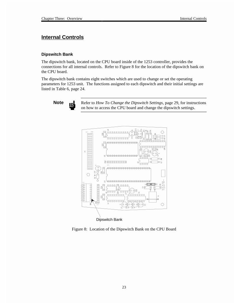
The dipswitch bank, located on the CPU board inside of the 1253 controller, provides theconnections for all internal controls. Refer to Figure 8 for the location of the dipswitch bank onthe CPU board.
The dipswitch bank contains eight switches which are used to change or set the operatingparameters for 1253 unit. The functions assigned to each dipswitch and their initial settings arelisted in Table 6, page 24.
Note Refer to How To Change the Dipswitch Settings, page 29, for instructionson how to access the CPU board and change the dipswitch settings.
Dipswitch Bank
Figure 8: Location of the Dipswitch Bank on the CPU Board
Internal Controls Chapter Three: Overview
24
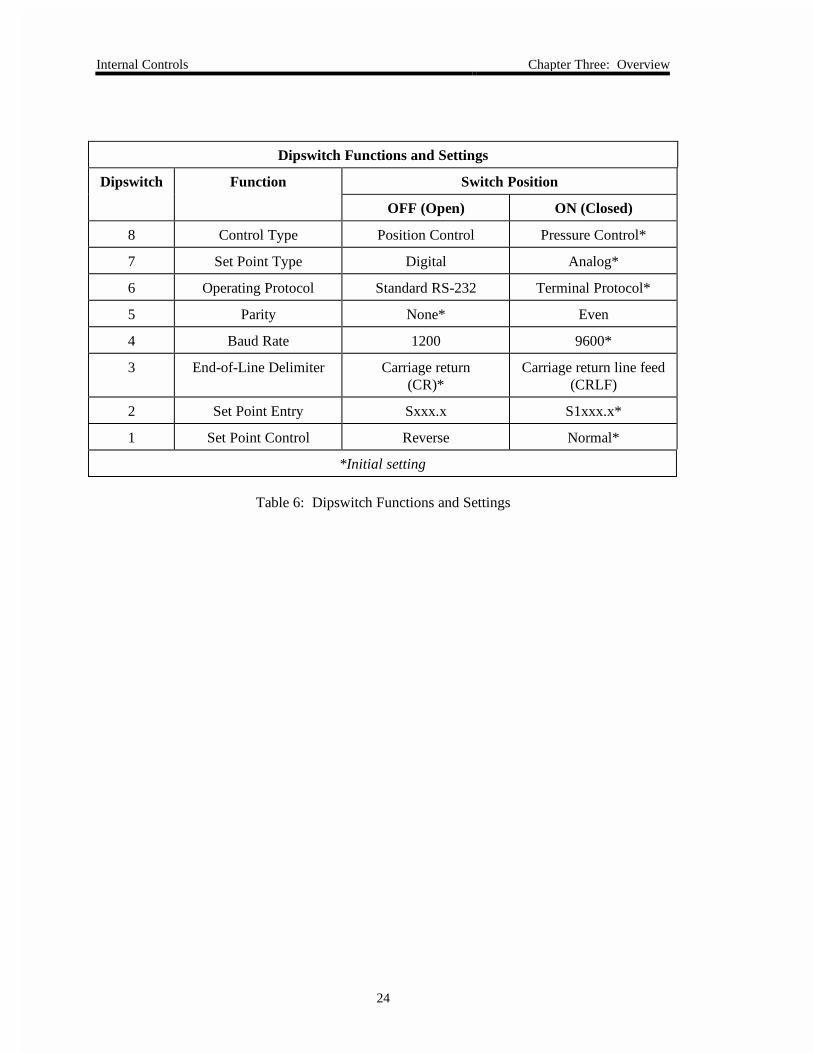
Dipswitch Functions and Settings
Dipswitch Function Switch Position
OFF (Open) ON (Closed)
8 Control Type Position Control Pressure Control*
7 Set Point Type Digital Analog*
6 Operating Protocol Standard RS-232 Terminal Protocol*
5 Parity None* Even
4 Baud Rate 1200 9600*
3 End-of-Line Delimiter Carriage return(CR)*
Carriage return line feed(CRLF)
2 Set Point Entry Sxxx.x S1xxx.x*
1 Set Point Control Reverse Normal*
*Initial setting
Table 6: Dipswitch Functions and Settings
Chapter Three: Overview Internal Controls
25
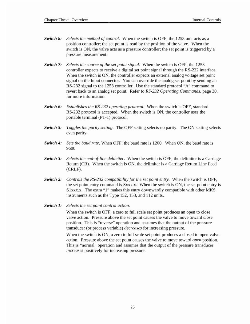
Switch 8: Selects the method of control. When the switch is OFF, the 1253 unit acts as aposition controller; the set point is read by the position of the valve. When theswitch is ON, the valve acts as a pressure controller; the set point is triggered by apressure measurement.
Switch 7: Selects the source of the set point signal. When the switch is OFF, the 1253controller expects to receive a digital set point signal through the RS-232 interface.When the switch is ON, the controller expects an external analog voltage set pointsignal on the Input connector. You can override the analog set point by sending anRS-232 signal to the 1253 controller. Use the standard protocol “A” command torevert back to an analog set point. Refer to RS-232 Operating Commands, page 30,for more information.
Switch 6: Establishes the RS-232 operating protocol. When the switch is OFF, standardRS-232 protocol is accepted. When the switch is ON, the controller uses theportable terminal (PT-1) protocol.
Switch 5: Toggles the parity setting. The OFF setting selects no parity. The ON setting selectseven parity.
Switch 4: Sets the baud rate. When OFF, the baud rate is 1200. When ON, the baud rate is9600.
Switch 3: Selects the end-of-line delimiter. When the switch is OFF, the delimiter is a CarriageReturn (CR). When the switch is ON, the delimiter is a Carriage Return Line Feed(CRLF).
Switch 2: Controls the RS-232 compatibility for the set point entry. When the switch is OFF,the set point entry command is Sxxx.x. When the switch is ON, the set point entry isS1xxx.x. The extra “1” makes this entry downwardly compatible with other MKSinstruments such as the Type 152, 153, and 112 units.
Switch 1: Selects the set point control action.
When the switch is OFF, a zero to full scale set point produces an open to closevalve action. Pressure above the set point causes the valve to move toward closeposition. This is “reverse” operation and assumes that the output of the pressuretransducer (or process variable) decreases for increasing pressure.
When the switch is ON, a zero to full scale set point produces a closed to open valveaction. Pressure above the set point causes the valve to move toward open position.This is “normal” operation and assumes that the output of the pressure transducerincreases positively for increasing pressure.
Power-Down Constants Chapter Three: Overview
26
Power-Down Constants
The 1253 unit saves the several constants in non-volatile RAM when the power is turned off.When the power is restored, the 1253 unit “remembers” these settings.
The parameters are:
• Number of valve steps
• Analog set point zero
• Analog pressure zero
• Analog set point full scale
• Analog pressure full scale
• Lead
• Gain
• Present valve position
The following conditions apply at power-up:
• The processor checks the position of all switches on thedipswitch bank.
• The operational mode is determined by dipswitches 7 and 8.
If dipswitches 7 and 8 are ON, the unit “wakes up” inpressure control mode and uses an analog set point.
If dipswitches 7 and 8 are OFF, the unit “wakes up” inposition control mode and uses a digital set point.
The stored constants are recalled and used in all subsequent operations.
Chapter Four: Operation General Information
27
Chapter Four: Operation
General Information
The 1253 controller can communicate with an external computer or a portable terminal (PT-1)through the RS-232 interface. Although the setup varies slightly, operation is the sameregardless of whether you are using a computer or the PT-1. The computer can read pressure,valve position, and tuning parameters. It can also change the set point, open and close the valve,and change the tuning parameters.
The 1253 controller accepts pressure or position set points from an external computer, throughRS-232 communications or an external analog voltage source, and uses an internal digital “PID”algorithm to determine valve position.
When the set point is under pressure control, the feedback is an analog pressure signal. Thissignal is normally 0 to +10 Volts, but the zero and full scale voltages can be adapted toindividual applications. The Gain and Lead constants used in the control algorithm are set at thefactory but are adjustable via RS-232 commands, using either a computer or a portable terminal.
When the set point is under position control, the valve is moved as a result of the position controlcommand, and no feedback signal is generated.

RS-232 Communication Parameters Chapter Four: Operation
28
RS-232 Communication Parameters
The initial RS-232 communication parameters for the 1253 unit are listed in Table 7. Ensure thatboth your 1253 controller and your computer are configured with the same parameters.
Initial RS-232 Communication Parameters
Parameter Value
Stop Bit* 1
Data Bits* 8
Handshaking* None
Parity** None
Baud Rate** 9600
End-of-Line Delimiter** CR
Operating Protocol** Standard RS-232or
Terminal Protocol (initial)
* These parameters are factory set and cannot be adjusted.
** These parameters are user-adjustable; refer to Table 6, page 24, for moreinformation.
Table 7: Initial RS-232 Communication Parameters
To change any of the user-adjustable parameters, you must change the dipswitch settings on theCPU board. Refer to How To Change the Dipswitch Settings, page 29, for instructions on how toaccess the CPU board and change the dipswitch settings.
The communication parameters are identical regardless of your choice of hardware, except for theoperating protocol. Ensure that you specify whether you are using a remote computer or the PT-1 portable terminal, by setting dipswitch 6 to the desired position as listed in Table 6, page 24
Note .When using the PT-1 unit, the 1253 unit must be configured with thedefault dipswitch settings (refer to Table 6, page 24). When configuredproperly, the 1253 unit accepts RS-232 characters from the PT-1 withoutneeding the shift key on the portable terminal.
Chapter Four: Operation RS-232 Communication Parameters
29
How To Change the Dipswitch Settings
The dipswitches located on the CPU board (refer to Figure 8, page 23) control the operating andcommunication parameters for the 1253 controller. To set or change any parameter, you mustchange the position of the appropriate dipswitch. Refer to Table 6, page 24, for a completelisting of the functions assigned to each dipswitch and their initial settings.
To change the dipswitch settings:
1. Disconnect the power source from the 1253 controller.
Warning To avoid an electrical shock, disconnect the power cordbefore opening the unit.
2. Unscrew the 16 screws (6 screws on the front, 2 on the bottom, and 8 on the top) on theunit and lift off the cover.
3. Locate the CPU board and the dipswitch bank.
There are two boards inside of the 1253 unit; the CPU board in the small, top mostboard. Refer to Figure 8, page 23, for the location of the dipswitch bank.
4. Change the position of any of the dipswitches as required.
Refer to Table 6, page 24, for a complete listing of the functions assigned to eachdipswitch and their initial settings.
5. Replace the cover of the unit and the secure it in place with the 16 screws.
6. Power up the 1253 controller.
Note You must repower the system before any changes to the dipswitch settingare recognized by the 1253 unit.
RS-232 Operating Commands Chapter Four: Operation
30
RS-232 Operating Commands
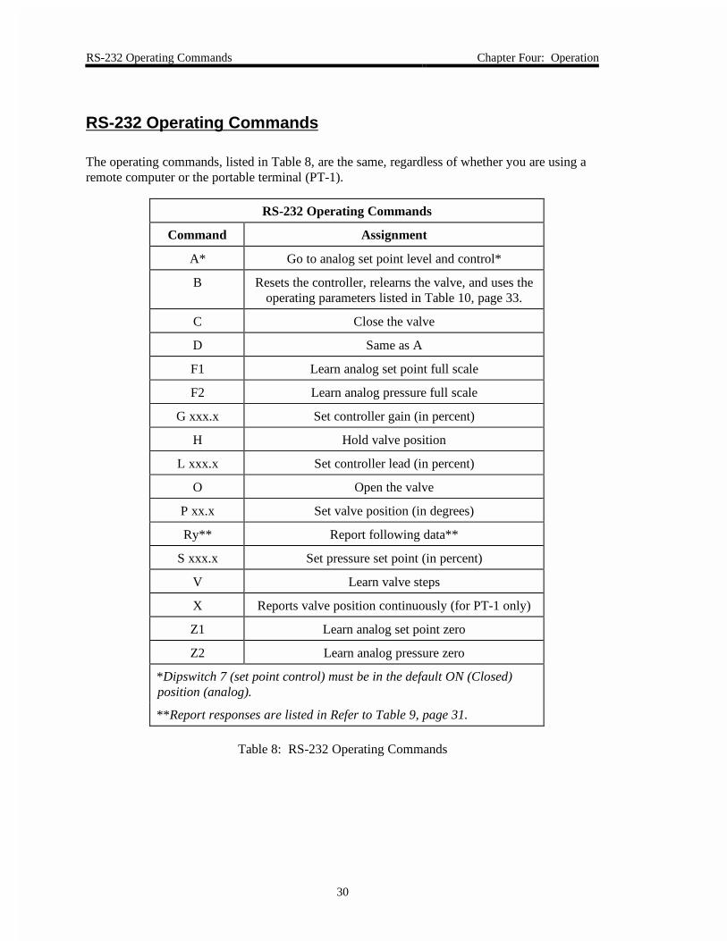
The operating commands, listed in Table 8, are the same, regardless of whether you are using aremote computer or the portable terminal (PT-1).
RS-232 Operating Commands
Command Assignment
A* Go to analog set point level and control*
B Resets the controller, relearns the valve, and uses theoperating parameters listed in Table 10, page 33.
C Close the valve
D Same as A
F1 Learn analog set point full scale
F2 Learn analog pressure full scale
G xxx.x Set controller gain (in percent)
H Hold valve position
L xxx.x Set controller lead (in percent)
O Open the valve
P xx.x Set valve position (in degrees)
Ry** Report following data**
S xxx.x Set pressure set point (in percent)
V Learn valve steps
X Reports valve position continuously (for PT-1 only)
Z1 Learn analog set point zero
Z2 Learn analog pressure zero
*Dipswitch 7 (set point control) must be in the default ON (Closed)position (analog).
**Report responses are listed in Refer to Table 9, page 31.
Table 8: RS-232 Operating Commands
Chapter Four: Operation RS-232 Requests and Response Messages
31
RS-232 Requests and Response Messages
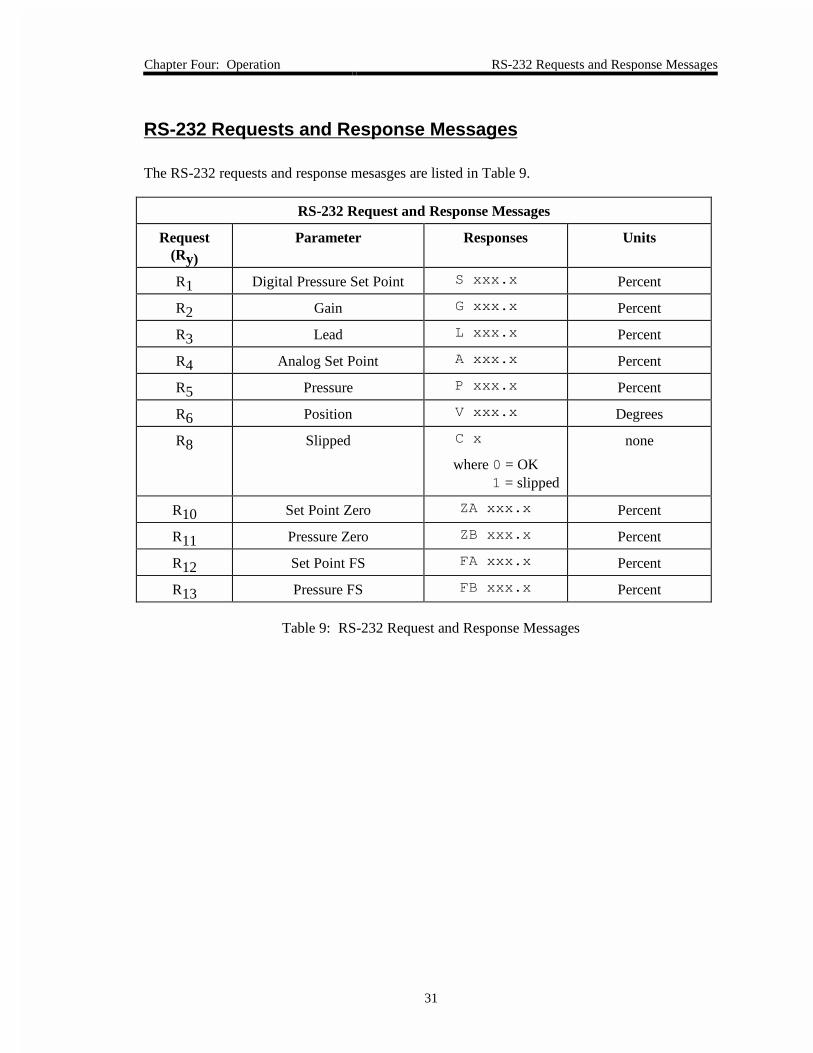
The RS-232 requests and response mesasges are listed in Table 9.
RS-232 Request and Response Messages
Request(Ry)
Parameter Responses Units
R1 Digital Pressure Set Point S xxx.x Percent
R2 Gain G xxx.x Percent
R3 Lead L xxx.x Percent
R4 Analog Set Point A xxx.x Percent
R5 Pressure P xxx.x Percent
R6 Position V xxx.x Degrees
R8 Slipped C x
where 0 = OK1 = slipped
none
R10 Set Point Zero ZA xxx.x Percent
R11 Pressure Zero ZB xxx.x Percent
R12 Set Point FS FA xxx.x Percent
R13 Pressure FS FB xxx.x Percent
Table 9: RS-232 Request and Response Messages
How To Learn the Valve Chapter Four: Operation
32
How To Learn the Valve
Since the valve is external to the 1253 controller and it is not always possible to match thecontroller to the valve at the factory, you must instruct the unit to learn the valve it is controllingto ensure proper control.
The learn process is initiated using RS-232 commands, on either a PC or a MKS PT-1 portableterminal. Refer to RS-232 Communication Parameters, page 28, for more information.
Note Regardless of the communication device used, the control characters usedare identical.
1. Ensure that your system is configured to withstand the change in valve position from thefully open to fully closed position.
Otherwise, your system may be damaged during this procedure.
2. Verify that the 1253 unit is powered on and connected to the correct valve with cable.
The system interface cables are listed in Table 2, page 8.
3. Enter the command:
V ENTER
The 1253 unit initiates the learn process. During the learning mode, the 1253 unit drivesthe valve from the fully closed to the fully open position.
4. Enter the command:
C ENTER
The 1253 unit drives the valve to the fully closed position.
Refer to How To Calibrate the Controller, page 35, for more information on the commands.
Chapter Four: Operation How To Reset the 1253 Controller
33
How To Reset the 1253 Controller
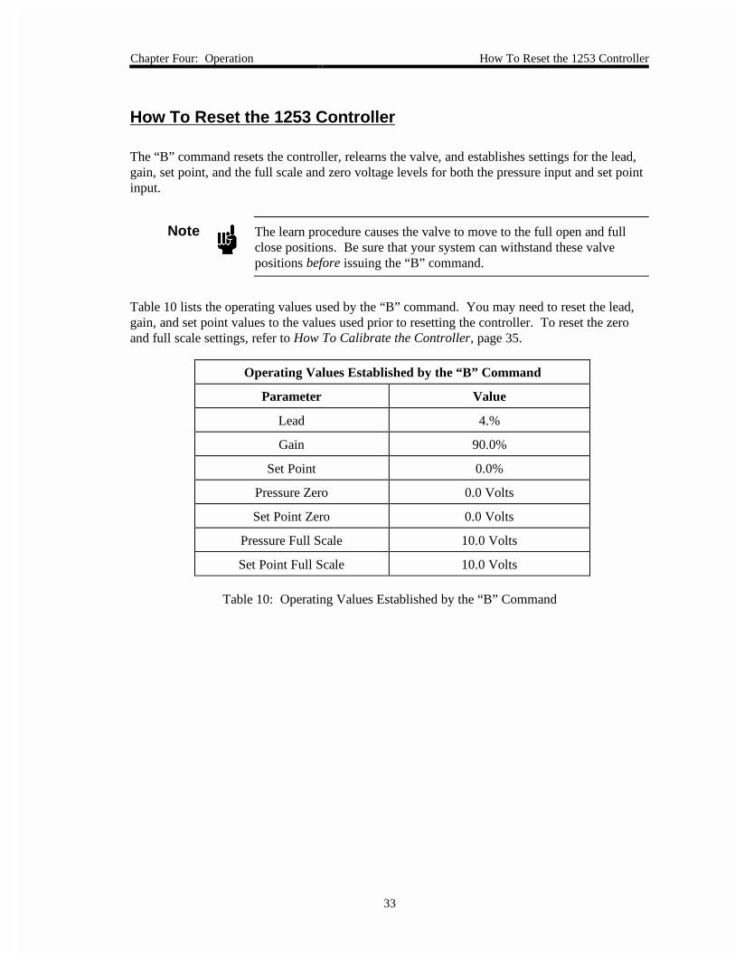
The “B” command resets the controller, relearns the valve, and establishes settings for the lead,gain, set point, and the full scale and zero voltage levels for both the pressure input and set pointinput.
Note The learn procedure causes the valve to move to the full open and fullclose positions. Be sure that your system can withstand these valvepositions before issuing the “B” command.
Table 10 lists the operating values used by the “B” command. You may need to reset the lead,gain, and set point values to the values used prior to resetting the controller. To reset the zeroand full scale settings, refer to How To Calibrate the Controller, page 35.
Operating Values Established by the “B” Command
Parameter Value
Lead 4.%
Gain 90.0%
Set Point 0.0%
Pressure Zero 0.0 Volts
Set Point Zero 0.0 Volts
Pressure Full Scale 10.0 Volts
Set Point Full Scale 10.0 Volts
Table 10: Operating Values Established by the “B” Command
How To Tune the Controller Chapter Four: Operation
34
How To Tune the Controller
1. Apply power to the 1253 unit and turn on the upstream gas source(s).
2. Apply the desired analog set point signal or an RS-232 message.
The 1253 unit responds by changing the pressure smoothly to the desired value. If thepressure is slow changing to the desired value (over 30 seconds), or oscillates, thenadjust the LEAD and/or GAIN. Use the RS-232 communication link to change theLEAD and GAIN values. Refer to RS-232 Operating Commands, page 30, for adescription of the control characters to use.
3. Increase the LEAD setting if the pressure overshoots the selected value.
If there is no overshoot, and particularly if the pressure is slow approaching the set pointvalue, then reduce the LEAD setting. Repeat this test to confirm that the LEAD settingis appropriate. Note that the correct LEAD setting for a rise in pressure is normally notthe same LEAD setting for a drop in pressure. Therefore, duplicate the test for theLEAD parameter with the same set point and direction as required in the process.
4. Reduce the GAIN setting if the pressure oscillates about the correct value.
The highest possible GAIN setting produces the best pressure control, therefore reducethe GAIN setting in very small increments.
Note The speed of pressure response is relative and depends on chamber sizeand absolute pressure. Lower pressures (less than 10 microns) are usuallyslower because of the slower molecular flow and reduced pumping speed.
The maximum rate of rise of pressure is determined by the following formula (with the exhaustvalve fully closed).
Pr = F/V
Where: Pr = pressure rate of rise in Torr/sec.F = flow in Torr-liters/sec.V = volume in liters
Consequently, in systems with small input flows and relatively large volumes, the pressure willrise slowly even when the control valve is fully closed.
If the controller cannot achieve good control, the problem may be caused by improper pneumaticconnections. Refer to System Considerations, page 12, to read about factors which effectpressure control.
Chapter Four: Operation How To Calibrate the Controller
35
How To Calibrate the Controller
The 1253 unit can perform five calibrations. They are:
• Learn the analog set point zero
• Learn the analog set point full scale
• Learn the analog pressure zero
• Learn the analog pressure full scale
• Learn the number of valve steps
You must issues these commands via RS-232 communications. To do this, connect a computeror a MKS PT-1 unit to the 1253 controller.
How To Calibrate the Analog Set Point
How To Learn the Analog Set Point Zero
1. Supply zero input voltage to pin 9 on the Input connector.
Refer to Table 5, page 16, for the Input connector pinout.
2. Send the Learn Analog Set Point Zero command:
Z1 ENTER
The 1253 controller learns the input voltage that corresponds to an analog set point zerovalue. The analog set point zero value is set to 0.0 Volts at the factory.
How To Learn the Analog Set Point Full Scale
1. Supply full scale input voltage to pin 9 on the Input connector.
Refer to Table 5, page 16, for the Input connector pinout.
2. Ensure that the input voltage is at least 9% of the 10 V full scale voltage.
If the voltage is less than 9% of the typical full scale voltage, the controller ignores thelearn command and retains the previous value. This eliminates the possibility of learningan erroneous voltage value.
3. Send the Learn Analog Set Point Full Scale command:
F1 ENTER
The 1253 controller learns the input voltage that corresponds to the analog set point fullscale value. The analog set point full scale value must be between +1 V and +10 Volts;it is set to +10.0 Volts at the factory.
How To Calibrate the Controller Chapter Four: Operation
36
How To Calibrate the Transducer Range
When a voltage enters the 1253 controller as a calibration signal, for a pressure zero or pressurefull scale reading, the controller scales the signal to allow for a slightly overrange or underrangesignal. The controller does not convert the signal back to a full 0 to 10 V range. Therefore,when you query the controller for a pressure zero or pressure full scale reading, it will return theoffset value, rather than the true zero or full scale voltage reading.
How To Learn the Analog Pressure Zero
1. Warm-up the transducer and pump it below its resolution.
Refer to the appropriate transducer manual for the time required to warm up the unit andthe proper zero pressure.
2. Send the Learn Analog Pressure Zero command:
Z2 ENTER
The 1253 controller verifies that the pressure transducer is properly warmed-up andpumped below its resolution. The 1253 controller learns the pressure input thatcorresponds to the analog pressure zero value. The analog pressure zero value is factoryset to 0.0 Volts.
How To Learn the Analog Pressure Full Scale
1. Warm-up the transducer and set up the pressure system for full scale pressure.
Refer to the appropriate transducer manual for the time required to warm up the unit andthe proper zero pressure.
2. Ensure that the input voltage is at least 9% of the 10 V full scale voltage.
If the voltage is less than 9% of the typical full scale voltage, the 1253 controller ignoresthe learn command and retains the previous value. This eliminates the possibility oflearning an erroneous voltage value.
3. Send the Learn Analog Pressure Full Scale command:
F2 ENTER
The 1253 controller raises the pressure to the full scale value of the transducer. The unitlearns the pressure input that corresponds to the analog pressure full scale value. Theanalog pressure full scale value is factory set to +10.0 Volts.
Chapter Four: Operation How To Calibrate the Controller
37
How To Learn the Number of Valve Steps
The 1253 controller opens and closes the valve, so be sure that it will not affect your system.
1. Send the Learn Number of Valve Steps command:
V ENTER
The unit is factory set for the attached valve.

How To Connect the Controller to the Type 146 Cluster Gauge™ Chapter Four: Operation
38
How To Connect the Controller to the Type 146 Cluster Gauge™
The Type 146 Cluster Gauge can be used to control the 1253 unit. To configure the 1253 unit tocommunicate with the 146 instrument, leave the dipswitches at the default settings (refer to Table6, page 24) except for switch 8. Set switch 8 to the OFF (Closed) position, so the unit will act asa position controller. The system will then use the PID control on the 146 instrument to controlthe valve. Refer to How To Change the Dipswitch Settings, page 29, for instructions on how tochange the position of switch 8.
Note The 146 instrument must contain the optional “M” board (Control Board)to control the 1253 unit.
1. Connect the 1253 controller to the “M” board (Control Board) in the 146 instrumentusing the appropriate cable.
The Control Board has two 9-pin Type “D” connectors: one male and one female. Thecable uses the 146 instrument to power the 1253 unit and provides the analog voltage toposition the valve to control pressure. The system interface cables are listed in Table 2,page 8.
2. Use the Setup Mode Code 14x, on the 146 instrument to select the control action (directfor downstream control) and the pressure reference channel.
3. Use the Open and Close commands on the 146 instrument to move the valve from fullyopen to fully closed.
4. Watch the Open and Close LED lights on the 1253 unit.
If the appropriate light is illuminated when the valve is in position, the zero and full scalesettings are correct. If the appropriate light is not illuminated correctly, proceed to step5.
5. Calibrate the 1253 controller using either a remote computer or a PT-1 portable terminal.
The 1253 unit will learn the new values for zero and full scale for the controller andtransducer. Refer to How To Calibrate the Controller, page 35, for details.
Chapter Five: Maintenance and Troubleshooting General Information
39
Chapter Five: Maintenance and Troubleshooting
General Information
If the 1253 instrument fails to operate properly upon receipt, check for shipping damage, andcheck the cables for continuity. Any damage should be reported to the carrier and MKSInstruments immediately. If it is necessary to return the unit to MKS, obtain an ERA number(Equipment Return Authorization Number) from a MKS Service Center before shipping. Pleaserefer to the inside back cover of this manual for a list of MKS Calibration and Service Centers.
Maintenance
Periodically check for wear on the cables and inspect the enclosure for visible signs of damage.
Troubleshooting
Valve Slippage Signal
The 1253 unit has a “Valve Slipped” signal that can be useful when diagnosing exhaust valve orsystem problems. The Valve Slipped signal is only available through the RS-232 interface.
When the 1253 unit contacts either of the limit switches, the internal position signal should equalthe appropriate valve position (0 for close, 100% for open). If the position signal is more than3% different from the appropriate value, the Valve Slipped signal is set to “1” (meaning slipped).
When message R8 is sent to the 1253 unit, the unit returns either C0 or C1 (refer to Table 9, page31). C0 indicates the valve has not slipped. C1 indicates the valve has slipped since the lastrequest (R8). The signal is reset to 0 when it is read by the computer or PT-1.
Situations that can cause the valve to slip include:
• The flapper is moved while the 1253 unit is turned off
• The flapper is rubbing or contacting part of the plumbing
• Particulates are depositing on the wall and slowing the flapper motion

Troubleshooting Chapter Five: Maintenance and Troubleshooting
40
This page intentionally left blank.
Appendix A: Product Specifications
41
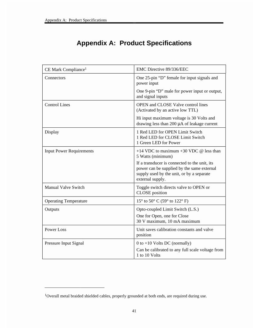
Appendix A: Product Specifications
CE Mark Compliance1 EMC Directive 89/336/EEC
Connectors One 25-pin “D” female for input signals andpower input
One 9-pin “D” male for power input or output,and signal inputs
Control Lines OPEN and CLOSE Valve control lines(Activated by an active low TTL)
Hi input maximum voltage is 30 Volts anddrawing less than 200 µA of leakage current
Display 1 Red LED for OPEN Limit Switch1 Red LED for CLOSE Limit Switch1 Green LED for Power
Input Power Requirements +14 VDC to maximum +30 VDC @ less than5 Watts (minimum)
If a transducer is connected to the unit, itspower can be supplied by the same externalsupply used by the unit, or by a separateexternal supply.
Manual Valve Switch Toggle switch directs valve to OPEN orCLOSE position
Operating Temperature 15° to 50° C (59° to 122° F)
Outputs Opto-coupled Limit Switch (L.S.)
One for Open, one for Close30 V maximum, 10 mA maximum
Power Loss Unit saves calibration constants and valveposition
Pressure Input Signal 0 to +10 Volts DC (normally)
Can be calibrated to any full scale voltage from1 to 10 Volts
1Overall metal braided shielded cables, properly grounded at both ends, are required during use.
Appendix A: ProductSpecifications
42
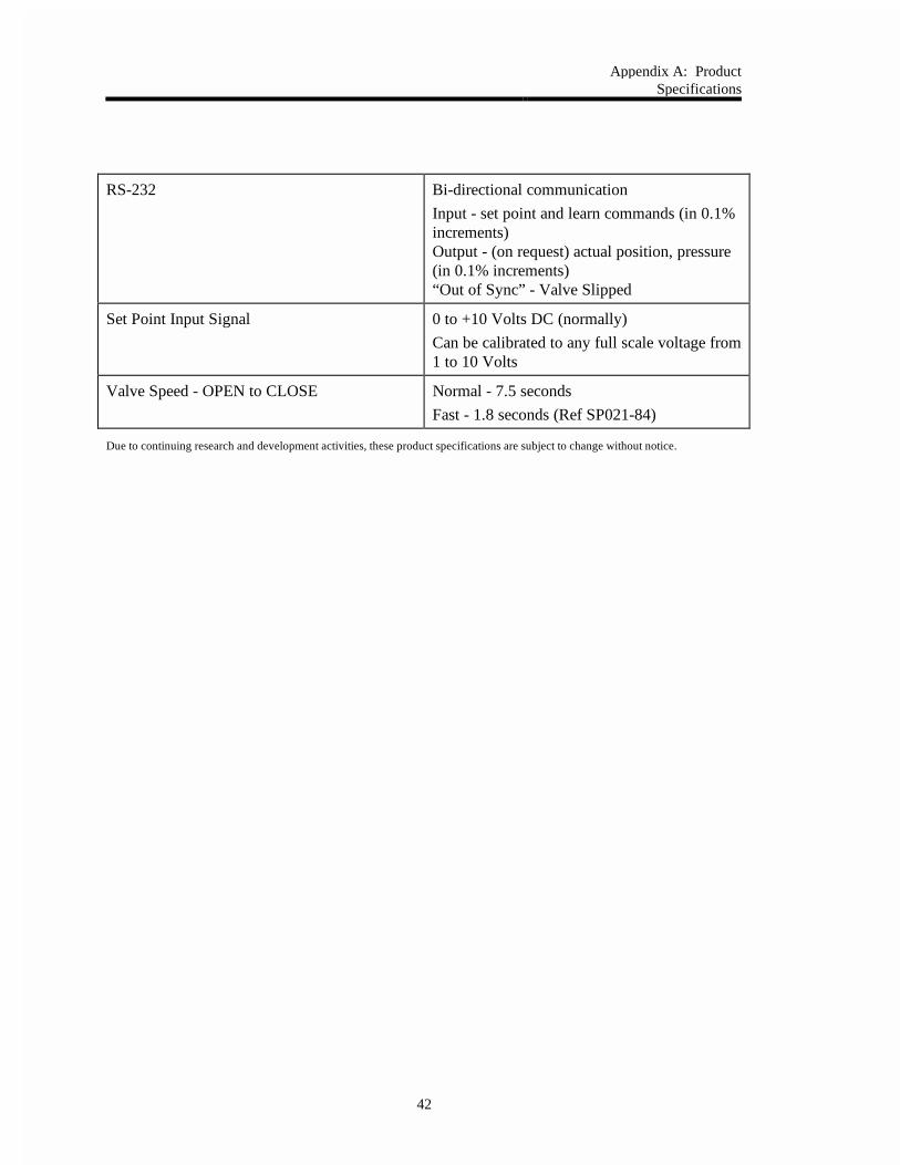
RS-232 Bi-directional communication
Input - set point and learn commands (in 0.1%increments)Output - (on request) actual position, pressure(in 0.1% increments)“Out of Sync” - Valve Slipped
Set Point Input Signal 0 to +10 Volts DC (normally)
Can be calibrated to any full scale voltage from1 to 10 Volts
Valve Speed - OPEN to CLOSE Normal - 7.5 seconds
Fast - 1.8 seconds (Ref SP021-84)
Due to continuing research and development activities, these product specifications are subject to change without notice.

Appendix B: Model Code Explanation
43
Appendix B: Model Code Explanation
Model Code
The 1253 controller is identified as the Type 1253E.
Portable RS-232 Terminal
The hand-held RS-232 terminal used for setup and diagnostics is ordered separately and isidentified as the Type PT-1A.

Appendix B: Model Code Explanation
44
This page intentionally left blank.
Index
45
Index
1
1253, description of, 5
C
Cables, 7
CE requirements, 8, 9
part numbers, 8
Cables and connectors, 13
input connector, 16
power connector, 15
valve connector, 14
Calibration, 35
Calibration voltages, 36
CE mark
cables, 8, 9
description of, 8
Control method selection, 25
Control parameters, 27
Control parameters, setting, 34
Customer support, 6
D
Dipswitch bank, 28
Dipswitch settings, changing, 29
I
Input connector, 16
Introduction, 5
L
Learn commands, 35
Learning the valve, 32
M
Maintenance, 41
Manual organization, 6
N
Normal/Reverse switch, 25
P
Portable terminal protocol, 30
Position control, 5
Power connector, 15
Power down constants, 26
Power requirements, 5, 12
Pressure control, 5
R
Returning the product, 6, 7
RS-232 communication
end-of-line delimiter, 25
MKS PT-1, 18
parity, setting, 25
portable terminal protocol, 30
protocol, selecting, 25
S
Safety messages, definitions of, 1

Index
46
Safety procedures and precautions, 3
Set point, 27
control action, 25, 26
signal source, 25
Setup
controller, mounting, 12
Standard protocol, 30–31
Symbols, definitions of, 2
T
Tuning, 34
V
Valve connector, 14
Valve slippage signal, 41