Embed Size (px)
Citation preview

Minimally invasive, percutaneous, reconstructive treatment for vertebral body fractures
VBS – Vertebral Body Stenting System
Surgical Technique

Image intensifier control
This description alone does not provide sufficient background for direct use of DePuy Synthes products. Instruction by a surgeon experienced in handling these products is highly recommended.
Processing, Reprocessing, Care and MaintenanceFor general guidelines, function control and dismantling of multi-part instruments, as well as processing guidelines for implants, please contact your local sales representative or refer to:http://emea.depuysynthes.com/hcp/reprocessing-care-maintenanceFor general information about reprocessing, care and maintenance of Synthes reusable devices, instrument trays and cases, as well as processing of Synthes non-sterile implants, please consult the Important Information leaflet (SE_023827) or refer to: http://emea.depuysynthes.com/hcp/reprocessing-care-maintenance

VBS – Vertebral Body Stenting System Surgical Technique DePuy Synthes 1
Table of Contents
Introduction VBS – Vertebral Body Stenting System 2
AO Principles 4
Indications and Contraindications 5
Surgical Technique Preoperative Planning 6
Preparation 7
Patient Positioning 10
Access Options 11
Instrument Positioning 12• A With Guide Wires 12• A1 Transpedicular Access 13• A2 Extra-/Parapedicular Access 16
Instrument Positioning 19• B With Trocars 19• B1 Transpedicular Access 20• B2 Extra-/Parapedicular Access 21
Create Access Channel 22
Determine Length of Stent 23
Optional: Use of VBB 24
Inflation of VBB 29
Using the VBS Catheter 33
Deployment of Stents 37
Cement Augmentation 41
Product Information Implants and Balloon-Catheters 43
Instruments 45
Bibliography 47

2 DePuy Synthes VBS – Vertebral Body Stenting System Surgical Technique
VBS is a treatment method for pain-ful vertebral body fractures and lesions. It helps to prevent effects such as postural damage and pain caused by postural kyphosis.
Vertebral Body Balloon (VBB)Simulate stent expansion in the verte-bral body prior to VBS insertion.
VBS – Vertebral Body Stenting System. Minimally invasive, percutaneous, reconstructive treatment for vertebral body fractures.
Minimally invasive, percutaneous insertion of the Vertebral Body Stenting SystemInstrument insertion through a stab incision allows performing the pro-cedure under either local or general anaesthesia.
VBS offers unique benefits to patients and physicians:
PercutaneousThe VBS stents are introduced per-cutaneously into the vertebral body with only a stab incision required to place the access instruments.
ReconstructiveThe VBS system restores the loss of height in the fractured vertebral body.
Height conservingExpanding the VBS stents inside the collapsed vertebra offers height restoration and conservation. The mechanical construct restores the height while at the same time offer-ing a cavity for injection of highly viscous PMMA based bone cement cleared for use in vertebro plasty or kyphoplasty procedures.

Restoration through balloondilatation and stent expansionSimultaneous dilatation of the bi-laterally positioned VBS Stents offers an in situ controlled and continuous expansion.
Optional Vertebral Body Balloon pre-cavity creationSimulation of stent expansion via balloon trialing allows fracture/lesion mobility confirmation
Augmentation with Vertecem V+Vertecem V+ is a PMMA based bone cement for the treatment of verte-bral compression fractures:• About 27 minutes of working time • Excellent X-ray visibility
Expansion ratio up to 400%The Vertebral Body Stenting techno-logy offers an expansion ratio up to 400% for the reconstruction of collapsed vertebrae.
Controlled balloon dilatation with the VBS Inflation SystemThe applied pressure and injected volume of the mixture of saline solu-tion and contrast medium can con-stantly be monitored and controlled with the help of the phosphorescent display.
VBS – Vertebral Body Stenting System Surgical Technique DePuy Synthes 3

4 DePuy Synthes VBS – Vertebral Body Stenting System Surgical Technique
1 Müller ME, Allgöwer M, Schneider R, Willenegger H (1995) Manual of Internal Fixation. 3rd, exp. a. completely revised ed. 1991. Berlin, Heidelberg, New York: Springer
2 Aebi M, Arlet V, Webb JK (2007) AOSPINE Manual (2 vols), Stuttgart, New York: Thieme
In 1958, the AO formulated four basic principles, which have become the guidelines for internal fixation1. They are:• Anatomic reduction• Stable fixation• Preservation of blood supply• Early, active mobilization
The fundamental aims of fracture treatment in the limbs and fusion of the spine are the same. But a specific goal of spine treatment is to restore as much function as pos-sible to the injured neural elements.1
AO Principles as applied to the spine 2
Anatomic reductionRestoration of normal spine alignment improves the bio-mechanics of the spine and reduces pain by reestablish-ing and maintaining the natural curvature and the pro-tective function of the spine.
Stable fixationIn the spine, the goal of internal fixation is to maintain not only the integrity of a mobile segment, but also to maintain the balance and the physiologic three-dimen-sional form of the spine. A stable spinal segment allows bony fusion at the junction of the lamina and pedicle.
AO Principles
Preservation of blood supplyThe proper atraumatic technique enables minimal retrac-tion or disturbance of the nerve roots and dura, and maintains the stability of the facet joints. The ideal surgical technique and implant design minimize damage to anatomical structures, i.e. facet capsules and soft tissue attachment remain i ntact, and create a physio-logical environment that facilitates healing.
Early, active mobilizationThe ability to restore normal spinal anatomy may permit the immediate reduction of pain, resulting in a more active, functional patient. The reduction in pain and i mproved function can result when a stable spine is achieved.

VBS – Vertebral Body Stenting System Surgical Technique DePuy Synthes 5
Indications and Contraindications
Intended useThe VBS System is intended for the reduction of painful vertebral compression fractures and/or creation of a void in cancellous bone in the spine for the treatment of levels ranging from Th5–L5. It is intended to be used in combination with a legally-marketed PMMA 1 based bone cement adequately indicated for use in vertebro-plasty or kyphoplasty procedures.
Note: Refer to the manufacturer’s directions accom-panying the bone cement for specific information on its use, precautions and warnings. Indications• Painful osteoporotic vertebral compression fractures
without posterior wall involvement. Classified after Genant, Grade 2 and Grade 3.
• Painful vertebral compression fractures classified after the AO classification: A1.1 Endplate impaction A1.2 Wedge impaction fracture A1.3 Vertebral body collapse A3.1 Incomplete burst fracture; matter of discretion
(depending on the degree of posterior wall involvement, internal fixation must be used in addition)
In combination with internal fixation:A3.1 Incomplete burst fractureA3.2 Burst-split fracture; matter of discretion (the ex-
tent of the gap width should not be too wide)B1.2 Posterior disruption predominantly ligamentous
associated with type A fracture of the vertebral body
B2.3 Posterior disruption predominantly osseous with type A fracture of the vertebral body
• Palliative treatment of osteolytic lesions located within the vertebral body with intact cortical shell. Classified after Tomita Type 1.
Contraindications• Lesions requiring open anterior column reconstruction• Acute or chronic systemic or localized spinal infections
1 Note: Due to limited long-term efficacy data, the treating physician should weigh the benefits of the application of the PMMA based bone cement in younger patients against the potential risks.

6 DePuy Synthes VBS – Vertebral Body Stenting System Surgical Technique
Preoperative Planning
Patient assessmentRequirements for assessing the indication:• Current X-ray images, if possible in standing position,
of the thoracic and lumbar spine in two planes to assess the fracture and spinal alignment
• A spiral CT and MRI scan (ideally with STIR frequency) of the painful region of the spine
• If an MRI scan is contraindicated a bone scan may identify an acute fracture
• Ruling out another cause of pain• Feasibility of surgery and use of anaesthesia• Ruling out impaired clotting
Note: It is important, to treat only patients with non- consolidated fractures.
Warning: The patient should be checked for allergy to the contrast medium and stent material (CoCrWNi alloy). Planning of stent placement
The placement of the stents should be planned based on the AP image which gives hints for the route of insertion.
Pre-planning of stent sizeThe stent size for the procedure can roughly be planned preoperatively via CT scan.
Intraoperative X-ray imagingThe Vertebral Body Stent must be implanted using X-ray on both planes, two C-arms, or with one freely mobile C-arm.

1
2
VBS – Vertebral Body Stenting System Surgical Technique DePuy Synthes 7
Preparation
Instrument preparation
Instrument Set
03.804.512S Vertebral Body Stent Access Kit, sterile
Instrument
03.804.413S Inflation System, sterile
The inflation system has an angled manometer that shows the pressure in the balloon in pounds/inch2 (psi) and atmospheres (atm). The volume scale on the fluid chamber measures milliliters (ml).
It is necessary to prepare two inflation systems.
1. Connect inflation system to connectorAttach the tube of the inflation system with the Luer connector to the supplied 3-way connector as shown. Rotate the knob on the 3-way connector to position the “off” indicator towards the lateral outlet (1).
2. Fill inflation systemFill the inflation system with saline solution and a liquid contrast medium.
Note: It is essential to fill the inflation system with saline/contrast agent mixture to ensure better visi-bility of the VBS balloon catheter during inflation. The ratio of contrast medium to saline solution should be about 1:2.
Prepare the contrast medium mixture in a cup and place the 3-way connector under the solution. Push forward on the white wings on the inflation system and pull back on the handle until the plunger bottoms out. With the handle pointing upwards, tap the unit to clear the gauge portion of the inflation system of air (2).
White handle
White wings
Plunger with red marking

8 DePuy Synthes VBS – Vertebral Body Stenting System Surgical Technique
3Then hold the inflation system with the handle facing downward, and rotate the handle clockwise to expel all the air in the barrel until solution starts to emerge. Keep turning the handle clockwise until the leading edge of the red mark on the plunger reaches to approximately 3 to 4 ml under the zero marking or until the red marker on the plunger is aligned with the black line above the ml sign, underneath the zero marking (3).
The inflation system has now been prepared accordingly and can be set aside. Repeat for the second inflation system.
Tip: The white wings may be pushed to unlock the plunger when large changes to the handle position are desired. The handle must be moved carefully to avoid overshooting the desired target.
Warning: If the buttons (white wings) do not return to the locked position, do not force them as this could damage the plunger. Turn the handle gently, and the buttons (white wings) will return automati-cally to the locked position.
Preparation

~5 mm
1
VBS – Vertebral Body Stenting System Surgical Technique DePuy Synthes 9
Anatomical landmarksFor vertebral body augmentation with VBS, the two stents per vertebra should be placed in a symmetrical, paramedian position within the affected vertebral body to achieve optimum reduction of the spinal fracture without damaging the lateral vertebral body edges. Ideally, the distance from the compressed endplate to the stents should be about 5 mm (1).
The position of the stents needs to be planned based in preoperative imaging. Take care to achieve the planned position by determining the landmarks accordingly.
The following landmarks have to be defined on the spine:• Both pedicles• Spinous process• Endplates• Posterior wall of vertebral body

11 DePuy Synthes VBS – Vertebral Body Stenting System Surgical Technique
Patient Positioning
Place the patient in the prone position on a lumbar sup-port. The table must be radiolucent in both planes.
The OR table should allow free manipulation of the C-arm over the operative site in both planes.

1
2
VBS – Vertebral Body Stenting System Surgical Technique DePuy Synthes 11
Access Options
There are two access options to the targeted vertebral body, depending on its anatomy:
1. Transpedicular accessAs a general rule, the bilateral skin incisions for thetranspedicular approach are 1–2 cm lateral and up to 1 cm cranial to the centre of the pedicle (1).
2. Extra-/Parapedicular accessThe bilateral skin incisions for the extra-/parapedicular technique are planned according to the anatomical situa-tion (2).
The instruments for inserting the VBS system can be placed using either a guide wire or a trocar. In the chap-ter “Instrument Positioning” each procedure is explained for a transpedicular and an extra-/parapedicular access.
For positioning instruments with guide wires see page 12. For positioning instruments with trocar see page 19.

12 DePuy Synthes VBS – Vertebral Body Stenting System Surgical Technique
1
5 mm
Instrument Positioning
A With Guide WiresInstrument Set
03.804.512S Vertebral Body Stent Access Kit, sterile
First the guide wires are positioned. The other instru-mentation follows the path created by the guide wires.
Once the anatomical landmarks are detected, the guide wires can be percutaneously introduced through skin incisions using X-ray control (AP and lateral).
Either a transpedicular or extra-/parapedicular access may be selected depending on the anatomy of the verte-bral body to be treated.
Note: With either access technique it is important to plan to place the two stents symmetrically towards the midline and the anterior wall of the vertebral body at a medial location. In this position the stents have room to expand without pressing against either the lateral wall, or the other stent (1).

VBS – Vertebral Body Stenting System Surgical Technique DePuy Synthes 13
A1 Transpedicular Access
1. Position guide wires
Make the skin incisions.
Under AP and lateral X-ray control insert the guide wires to the superior outer pedicle quadrant using slight man-ual pressure.
Once the guide wires touch bone the outlines of the lat-eral pedicle are reached. Drive both guide wires with controlled blows from a hammer through the cortex. Cautiously advance the guide wires into the center of the vertebral body.
Note: The tips of the guide wires should be about and not closer than 5 mm to the anterior wall of the vertebral body. They should be positioned symmet-rically and aligned in both AP and lateral views. Confirm this placement for the positioning of the stents.
Warning: The tips of the guide wires must not pass the midline in AP view until they have passed the posterior wall in the lateral view. When advancing the guide wires, ensure that they are not inserted too far medially, to avoid penetration into the spinal canal. It is also essential to avoid over driving the guide wires into vascular structures beyond the an-terior cortical wall.

14 DePuy Synthes VBS – Vertebral Body Stenting System Surgical Technique
1
2
2. Position working sleeves over guide wires
Take the instrument assembly of working sleeve, side-opening cannula and cannulated trocar (1). Push the instrument assembly with a counterclockwise turning motion over the first guide wire (2).
Warning: Do not insert the working sleeve into the bone without the side-opening cannula. This could damage the working sleeve and obstruct stent inser-tion. Do not hammer on the side-opening cannula, cannulated trocar and working sleeve. The working sleeve can also be placed without the mounted cannulated trocar (working sleeve with side-opening cannula over guide wire). If this method is chosen, there is more clearance between the diameter of the guide wire and the side-opening cannula to allow for minor correction in the trajectory when positioning the working sleeve. This can lead to a slight resistance when penetrating the bony vertebral body surface.
Instrument PositioningA1 Transpedicular Access

4
5
6
VBS – Vertebral Body Stenting System Surgical Technique DePuy Synthes 15
Monitor working sleeve placement under lateral X-ray control. Ensure that the tip of the working sleeve has passed the pedicle and is positioned inside the vertebral body.
Note: When inserting the working sleeve, carefully monitor the position of the guide wire to confirm that it is not advancing forward.
Tip: Pull back the side-opening cannula to verify the positioning of the working sleeve.
Repeat on the contra-lateral side (4).
Once both working sleeves are in place, remove the side- opening cannulae with the inserted cannulated trocar and the guide wires (5).
The working sleeves remain in the vertebral body.
Warning: It is important to advance the instrument assembly carefully in order to avoid any injury to the physician’s hand. Since the guide wire is longer than the combined length of the pre-mounted work-ing sleeve with the side- opening cannula with can-nulated trocar, it will protrude through the handle of the side-opening cannula (6).

16 DePuy Synthes VBS – Vertebral Body Stenting System Surgical Technique
1. Position guide wires
Make the skin incisions.
Under AP and lateral X-ray control, insert the guide wires using slight manual pressure.
Insert both guide wires up to the vertebral body and drive them with controlled blows from a hammer through the cortex. Should you touch bone before reaching the vertebral body you have reached the out-line of the lateral pedicle.
Note: Cautiously advance the guide wires and, if necessary, redirect in order to reach the center of the vertebral body. The tips of the guide wires should be about and not closer than 5 mm to the anterior wall of the vertebral body.
Warning: The tips of the guide wires must not pass the midline in AP view until they have passed the posterior wall in the lateral view. When advancing the guide wires, ensure that they are not inserted too far medially, to avoid pene tration into the spinal canal. It is also essential to avoid overdriving the guide wires into vascular structures beyond the anterior cortical wall.
A2 Extra-/Parapedicular Access
Instrument Positioning

1
2
3
VBS – Vertebral Body Stenting System Surgical Technique DePuy Synthes 17
2. Positioning working sleeves over guide wires
Take the instrument assembly of working sleeve, side-opening cannula and cannulated trocar (1). Push the instrument assembly with a counterclockwise turning motion over the first guide wire (2).
Warning: Do not insert the working sleeve into the bone without the side-opening cannula. This could damage the working sleeve and obstruct stent inser-tion. Do not hammer on the side-opening cannula, cannulated trocar and working sleeve.
The working sleeve can also be placed without the mounted cannulated trocar (working sleeve with side-opening cannula over guide wire). Then, there is more clearance between the diameter of the guide wire and the side-opening cannula to allow for minor correc-tion in the trajectory when positioning the working sleeve. This can lead to a slight resistance when pene-trating the bony vertebral body surface (3).

18 DePuy Synthes VBS – Vertebral Body Stenting System Surgical Technique
4
5
6
Monitor working sleeve placement under lateral X-ray control. Advance the tip of the working sleeve until it has penetrated the cortex and is tightly seated into the bone.
Note: When inserting the working sleeve, carefully monitor the position of the guide wire to confirm that it is not advancing forward.
Tip: Pull back the side-opening cannula to verify the positioning of the working sleeve.
Repeat on the contra-lateral side (4).
Once both working sleeves are in place, remove the side- opening cannulae with the inserted cannulated trocar and the guide wires (5).
The working sleeves remain in the vertebral body.
Warning: It is important to advance the instrument assembly carefully in order to avoid any injury to the physician’s hand. The guide wire is longer than the combined length of the instrument assembly of working sleeve and the side- opening cannula and cannulated trocar will protrude through the handle of the side-opening cannula (6).
Instrument PositioningA2 Extra-/Parapedicular Access

VBS – Vertebral Body Stenting System Surgical Technique DePuy Synthes 19
Instrument Set
03.804.512S Vertebral Body Stent Access Kit, sterile
When using trocars for instrument positioning, creating the pathway and positioning of the instrumentation is achieved in one step.
Either a transpedicular or extra-/parapedicular access may be selected depending on the anatomy of the verte-bral body to be treated.
Note: With either access technique it is important to plan to place the two stents symmetrically towards the midline.
B With Trocars
Instrument Positioning

21 DePuy Synthes VBS – Vertebral Body Stenting System Surgical Technique
1
3
2
Positioning working sleeves
Make skin incisions.
Take the instrument assembly of working sleeve, side-opening cannula and cannulated trocar. Replace the cannulated trocar by the trocar and lock it into place with a clockwise rotation (1).
Under AP and lateral X-ray control insert the instrument assembly through the skin incision to the superior outer pedicle quadrant using slight manual pressure and a counterclockwise turning motion (2). If necessary the instrument assembly can be inserted through the cortex with light impaction on the metal end of the trocar using a hammer.
Tip: Pull back the side-opening cannula to verify the positioning of the working sleeve.
Warning: When advancing the instrument assembly, ensure that the trocar tip is not inserted too far me-dially, to avoid penetration into the spinal canal. It is also essential to avoid overdriving the trocar tip into vascular structures beyond the anterior corti-cal wall. Hold the working sleeve in place and carefully rotate and remove the trocar and the side-opening cannula. The working sleeve remains in the vertebral body.
Repeat for the contra-lateral side (3).
Warning: Do not insert the working sleeve into the bone without the side-opening cannula and trocar. This could damage the working sleeve and obstruct stent insertion. Do not redirect the instrument assembly without remov-ing it and re-accessing the pedicle.
B1 Transpedicular Access
Instrument Positioning

1
3
2
VBS – Vertebral Body Stenting System Surgical Technique DePuy Synthes 21
Positioning working sleeves
Make skin incisions.
Take the instrument assembly of working sleeve, side-opening cannula and cannulated trocar. Replace the cannulated trocar by the trocar and lock it into place with a clockwise rotation (1).
Under AP and lateral X-ray control insert the instrument assembly through the skin incision into the vertebral body using slight manual pressure and a counterclock-wise turning motion (2). If necessary the instrument assembly can be inserted through the cortex with light impaction on the metal end of the trocar using a hammer.
Advance the instrument assembly so that the opening of the working sleeve is anterior to the posterior wall of the vertebral body.
Tip: Pull back the side-opening cannula to verify the positioning of the working sleeve.
Warning: When advancing the instrument assembly, ensure that the trocar tip is not inserted too far me-dially, to avoid penetration into the spinal canal. It is also essential to avoid overdriving the trocar tip into vascular structures beyond the anterior corti-cal wall.
Hold the working sleeve in place and carefully rotate and remove the trocar and the side-opening cannula. The working sleeve remains in the vertebral body.
Repeat for the contra-lateral side (3).
Warning: Do not insert the working sleeve into the bone without the side-opening cannula and trocar. This could damage the working sleeve and obstruct stent insertion. Do not redirect the instrument assembly without removing it and re-accessing the bone.
B2 Extra-/Parapedicular Access

22 DePuy Synthes VBS – Vertebral Body Stenting System Surgical Technique
1
2
Create Access Channel
Instrument Set
03.804.512S Vertebral Body Stent Access Kit, sterile
Guide the drill (1) and afterwards the blunt plunger (2) through the working sleeves to create an access channel for the stents.
Warning: Use lateral X-ray intensification to avoid penetrating the anterior cortex of the vertebral body. It is essential to avoid overdriving these instru-ments into vascular structures beyond the anterior cortical wall.
Warning: Do not use a hammer to drive the drill forward. The drill may aggressively advance with rotation.
The plunger can be driven forward with light hammer blows. Ensure that the hammer blows hit the protruding metal pin and not the plastic handle (2).
Warning: While using drill or plunger, it is import-ant to ensure that the working sleeves do not move. Do not use the drill or plunger to manipulate or correct the direction of the working sleeve.
Repeat on the contra-lateral side.

1
VBS – Vertebral Body Stenting System Surgical Technique DePuy Synthes 23
The Vertebral Body Stents and Balloons are available in three sizes:
Vertebral Body Stent/Balloon
Article No. Max Stent B Stent length Release expanded expanded length (VBB/VBS)
09.804.500S 15 mm 13 mm 22 mm09.804.600SSmall
09.804.501S 17 mm 15 mm 27 mm09.804.601SMedium
09.804.502S 17 mm 20 mm 31 mm09.804.602SLarge
The plunger has three grooves towards the distal tip that correspond to the three stent lengths (1).
Use lateral imaging to select the length of the stent on the basis of these grooves.
From distal tip the first groove visible: Vertebral Body Stent SmallFrom distal tip the second groove visible: Vertebral Body Stent MediumFrom distal tip the third groove visible: Vertebral Body Stent Large
Establish the stent size on both sides, they may differ.
Determine Length of Stent
Release length
Stent length

24 DePuy Synthes VBS – Vertebral Body Stenting System Surgical Technique
1 2If you do not intend to use the VBB please continue to page 33 chapter “Using the VBS catheter”.
The VBS System can optionally be used with a Vertebral Body Balloon (VBB). The VBB allows simulating the stent expansion when bone quality, age of the fracture or the fracture/lesion mobility of the vertebral body is un-known.
1. Unpacking the VBB Catheter
Remove the VBB catheter from the sterile packaging (1).
Note: Slide back the white cover sleeve towards the Luer connector and attach it properly to the luer (2). This cover sleeve can be used later for stretching and folding back the VBB after catheter removal for reuse.
Do not remove the stiffening wire from the VBB cathe-ter. The stiffening wire will be removed and the creation of the vacuum will be performed after the insertion of the VBB catheter on the patient. This is different com-pared to the VBS catheter insertion.
There is a white marking range on the balloon catheter shaft indicating release length, i.e. the overall length and both proximal and distal balloon shoulders segments when the white marking range is completely inserted into the working sleeve.
The VBB can be reused once within one surgery.
Warning: Only use the VBB of same size together with the corresponding VBS.
Note: The shaft marker indicates when balloon is fully inserted, use X-ray while inflating with con-trast media.
Optional: Use of VBB
VB Balloon
Stiffening wire
White cover sleeve

1
VBS – Vertebral Body Stenting System Surgical Technique DePuy Synthes 25
2. Insertion of the VBB
Insert the VBB catheter under lateral X-ray control.
Note: The full release (initial) length of the VBB is outside when the proximal end of the white marking of the catheter shaft disappears into the working sleeve.
Check the position under X-ray control and confirm the desired position under AP view (1). It is important, that the whole balloon portion is positioned completely in-side the vertebra and that these inflatable segments have completely passed through the working sleeve. Make sure to position the VBB according to the antici-pated VBS position.
Repeat for the contra-lateral side.
Note: Simultaneous dilatation of bilateral inserted VBBs is recommended for optimal performance.
Note: Make sure to position the VBB according to the anticipated VBS position.

26 DePuy Synthes VBS – Vertebral Body Stenting System Surgical Technique
2
1
J
K
3. Connecting VBB catheter to inflation system and create vacuum
Instrument
03.804.413S Inflation System, sterile
Remove stiffening wire prior to connecting the VBB to the inflation system and keep it.
Note: Stiffening wire will be used for balloon refold-ing (in conjunction with the cover sleeve) and re-insertion.
Connect the prepared inflation systems with the selected VBB catheters using the Luer connector (1).
Note: It is important to ensure that all Luer connec-tors are securely attached. Loose connections may result in inaccurate filling volumes and pressures.
Push the white wings on the inflation system forward to unlock the handle. Pull the handle all the way back, and re-lease the wings to lock the handle in position. This pulls air out of the catheter, creating a vacuum inside it. The vacuum can be monitored on the display “vac” (2).
Warning: If the buttons (white wings) do not return to the locked position, do not force them as this could damage the plunger. Turn the handle gently, and the buttons (white wings) will return automati-cally to the locked position.
Optional: Use of VBB

3
4
VBS – Vertebral Body Stenting System Surgical Technique DePuy Synthes 27
Close the balloon catheter with the 3-way connector by posi tioning the “off” indicator towards the catheter. This retains the vacuum inside the catheter (3).
Hold the inflation system with the handle facing down-ward and turn the handle clockwise in order to set the volume scale to zero. This is done by turning the handle until the red ring on the plunger is precisely at “0” (4).
28 DePuy Synthes VBS – Vertebral Body Stenting System Surgical Technique
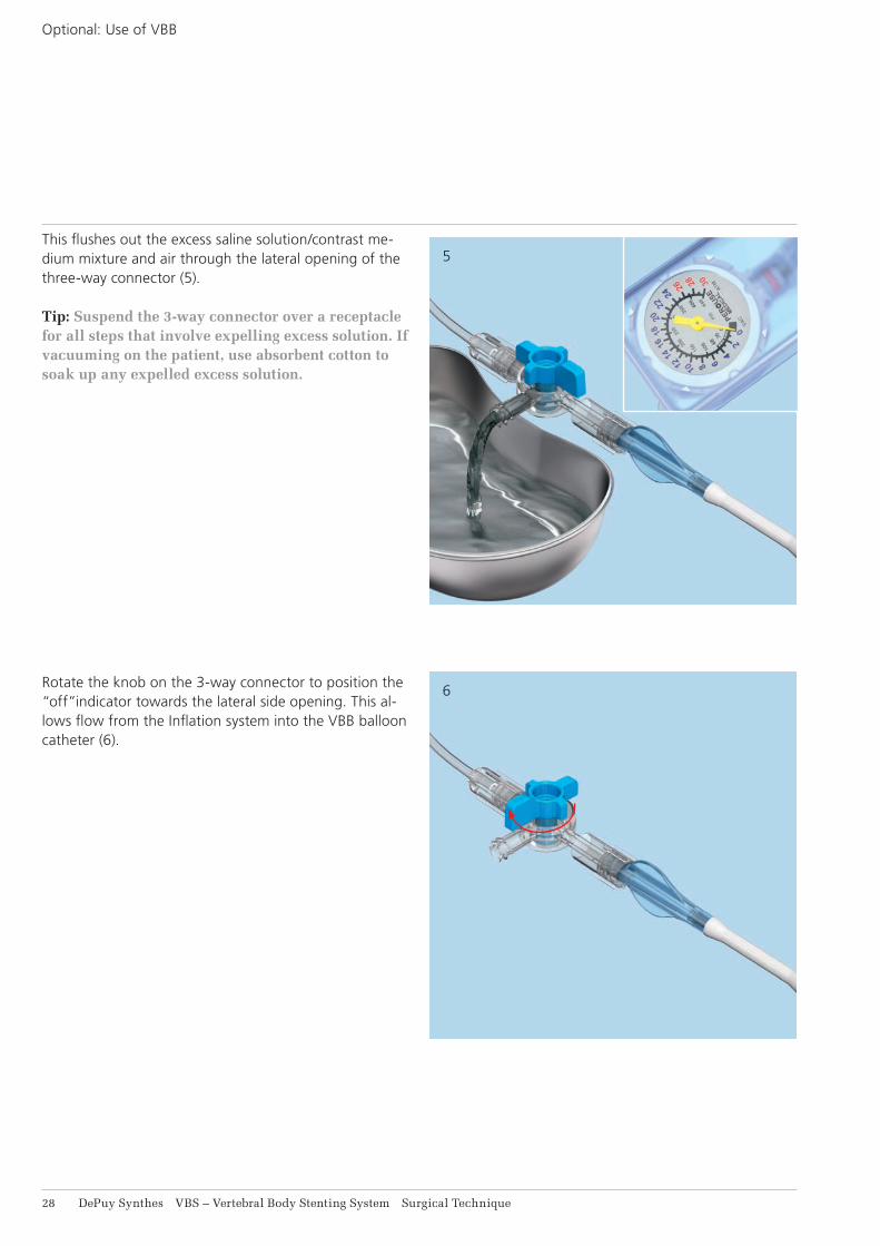
6
5This flushes out the excess saline solution/contrast me-dium mixture and air through the lateral opening of the three-way connector (5).
Tip: Suspend the 3-way connector over a receptacle for all steps that involve expelling excess solution. If vacuuming on the patient, use absorbent cotton to soak up any expelled excess solution.
Rotate the knob on the 3-way connector to position the “off”indicator towards the lateral side opening. This al-lows flow from the Inflation system into the VBB balloon catheter (6).
Optional: Use of VBB

2
VBS – Vertebral Body Stenting System Surgical Technique DePuy Synthes 29
Inflation of VBB
1. Inflation of VBB
Note: Simultaneous dilatation of bilateral devices is recommended for optimal performance.
Warning: It is essential to use AP and lateral X-rays to track VBB expansion via the balloon contrast me-dia solution inflation fluid.
Slowly increase pressure and volume by rotating the handles of the connected inflation systems in a clock-wise direction on both sides.
Proceed slowly after each VBB balloon unfolds and starts expanding at approx. 12 atm (2). Match the expansion bi laterally by tracking the fluid volume on the syringe body with the black volume markers positioned in ml increments. When the pressure reaches and increases beyond 26 atm, continue dilatation gradually. Wait a few seconds then slowly continue until the desired VBB diameter is reached (3). The maximum stent diameter is 15 mm for VBB Small and 17 mm for both VBB Medium and VBB Large.
Stop balloon expansion when any of the following happens:1. Desired vertebral body height or angle is reached 2. Pressure reaches 30 atm (400 PSI)3. VBB volume reaches maximum
• 4.0 ml for VBB Small • 4.5 ml for VBB Medium • 5.0 ml for VBB Large
Note: The VBB expansion pressure and volume on the inflation system have to be monitored carefully on the inflation system’s phosphorescent manometer (units: bar/atm, PSI) and syringe body with black volume markers (units: ml/cc), respectively.

31 DePuy Synthes VBS – Vertebral Body Stenting System Surgical Technique
1
2
Warning: Do not fill the balloons over their maxi-mum volume or pressure. If this is done, they may leak.
Warning: VBB maximum volumes differ from VBS maximum volumes!
Note: In case of contrast medium leakage, pull vac-uum, insert stiffening wire and remove balloon, don‘t reuse balloon.
2. Retrieve balloon catheters
Slowly turn the handles of the inflation systems counter- clockwise to draw the liquid out of the balloon catheter (1). Once the pressure has reached 10 atm, push the white wings forward, slowly pull the handle back all the way, and release the white wings (2). This draws and holds a vacuum in the catheter.
Inflation of VBB

1
2
VBS – Vertebral Body Stenting System Surgical Technique DePuy Synthes 31
Aerate the VBB catheter by first positioning the “off” indicator towards the catheter (1) and second turn back towards the lateral side opening (1 inset).
Disconnect the inflation system from the VBB catheter.
Note: Carefully insert the stiffening wire into the VBB catheter under X-ray control.
Apply a gentle force in order to stretch the deflated bal-loon prior to removal of the catheter (2). Make sure not to damage the VBB catheter by pushing too hard.
Hold the working sleeves in place and pull carefully on the catheters to retrieve the balloons. Rotate the cathe-ters if needed to ease balloon removal.
Note: The VBB catheter can be re-used once within one surgery. Make sure by visual inspection that the VBB catheter has not been damaged.
Warning: do not use a VBB catheter when a visual damage is observed, or when a leak is evident.
Warning: If balloon-catheter material is remaining in vertebral body after removal of the VBB do not leave it implanted. The balloon-catheter material is not implant grade material.

32 DePuy Synthes VBS – Vertebral Body Stenting System Surgical Technique
3Note: If the VBB catheter is planned to be reused within the same surgery, cover the re-folded balloon of the VBB catheter with the white cover sleeve (3) and reinsert stiffening wire to gently straighten the balloon.
Inflation of VBB

VBS – Vertebral Body Stenting System Surgical Technique DePuy Synthes 33
VB Stent
Stiffening wire
Note: The fracture must be mobile in order height restoration is possible. In order to simulate stent expansion use optional VBB (s. page 24)
1. Unpacking the VBS Catheters
Remove the VBS catheter from the sterile packaging. Carefully remove the stiffening wire and put it aside for possible further use.
If preferred, the stiffening wire can also be removed after the insertion of the balloon catheter. If this method is chosen, the creation of the vacuum has to be per-formed after the insertion of the balloon catheter on the patient.
There is a white marking range on the balloon catheter shaft indicating the release length, i.e. the overall length including the stent and both proximal and distal balloon shoulders segments, when the white marking range is completely inserted into the working sleeve.
Using the VBS Catheter

34 DePuy Synthes VBS – Vertebral Body Stenting System Surgical Technique
2
1
J
K
2. Connecting VBS catheter to inflation system and create vacuum
Instrument
03.804.413S Inflation System, sterile
Connect the prepared inflation system with the selected VBS balloon-catheters using the Luer connector (1).
Note: It is important to ensure that all Luer connec-tors are securely attached. Loose connections may result in inaccurate filling volumes and pressures.
Push the white wings on the inflation system forward to unlock the handle. Pull the handle all the way back, and re-lease the wings to lock the handle in position. This pulls air out of the catheter, creating a vacuum inside it. The vacuum can be monitored on the display “vac” (2).
Warning: If the buttons (white wings) do not return to the locked position, do not force them as this could damage the plunger. Turn the handle gently, and the buttons (white wings) will return automati-cally to the locked position.
Using the VBS Catheter

3
4
VBS – Vertebral Body Stenting System Surgical Technique DePuy Synthes 35
Close the balloon catheter with the 3-way connector by positioning the “off” indicator towards the catheter. This retains the vacuum inside the catheter (3).
Hold the inflation system with the handle facing down-ward and turn the handle clockwise in order to set the volume scale to zero. This is done by turning the handle until the red ring on the plunger is precisely at “0” (4).

36 DePuy Synthes VBS – Vertebral Body Stenting System Surgical Technique
5
6
This flushes out the excess saline solution/contrast me-dium mixture and air through the lateral opening of the three-way connector (5).
Tip: Suspend the 3-way connector over a receptacle for all steps that involve expelling excess solution. If vaccuuming on the patient, use absorbent cotton to soak up any expelled excess solution.
Rotate the knob on the 3–way connector to position the “off” indicator towards the lateral side opening. This al-lows flow from the inflation system into the VBS balloon catheter (6).
Using the VBS Catheter

1
VBS – Vertebral Body Stenting System Surgical Technique DePuy Synthes 37
Deployment of Stents
1. Insert and deploy stentsInsert the balloon catheter with the attached stent under lateral X-ray control. The full release (initial) length of the balloon with stent is outside the working sleeve when the proximal end of the white marking of the catheter shaft disappears into the working sleeve. Check the posi-tion under X-ray control and confirm the desired position under AP view (1). It is important, that the whole balloon portion including the stent is positioned completely in-side the vertebra and that these parts have completely passed through the working sleeve.
Repeat on the contra-lateral side.
Note: Simultaneous dilatation of bilateral devices is essential for optimal device performance. Once stent expansion has begun the stent cannot be undeployed or repositioned.
Warning: It is essential to use AP and lateral X-rays to track stent expansion and balloon shoulder in flation via the radiopacity due to the stent and the balloon contrast media solution inflation fluid, respectively.
Slowly increase pressure and volume by rotating the handles of the connected inflation system in a clockwise direction on both sides.

38 DePuy Synthes VBS – Vertebral Body Stenting System Surgical Technique
2
3
Proceed slowly after the stents begin expanding at approx. 12 atm (2). Match the expansion bilaterally by tracking the fluid volume on the scales. When the pres-sure reaches 26 atm, continue dilatation gradually. Wait a few seconds then slowly continue until the desired stent diameter is reached (3). The maximum stent dia-meter is 15 mm for VBS Small and 17 mm for both VBS Medium and VBS Large.
Stop balloon inflation when any of the following hap-pens:1. Desired vertebral body height or angle is reached 2. Pressure reaches 30 atm 3. VBS volume reaches maximum
• 4.5 ml for VBS Small • 5.0 ml for VBS Medium • 5.5 ml for VBS Large
Note: The VBS expansion pressure and volume on the inflation System have to be monitored carefully on the inflation system’s phosphorescent manometer (units: bar/atm, PSI) and syringe body with black volume markers (units: ml/cc), respectively.
Warning: Do not inflate the balloons beyond their maximum volume or pressure. If this is done, they may leak.
Warning: VBS maximum volumes differ from VBB maximum volumes.
Once the expansion is stopped, record the volume of solution used indicated on the inflation system.
Deployment of Stents

1
2
VBS – Vertebral Body Stenting System Surgical Technique DePuy Synthes 39
2. Retrieve balloon catheters
To maintain maximum stent expansion, gradually de-crease the pressure simultaneously on both sides. Slowly turn the handles of the inflation system counter-clock-wise to draw the liquid out of the balloon catheter (1). Once the pressure has reached 10 atm, push the white wings forward, slowly pull the handle back all the way, and release the white wings (2). This draws and holds a vacuum in the catheter and collapses the balloon for its removal.
Hold the working sleeves in place and pull firmly on the catheters to retrieve the balloons. Rotate the catheters if needed to ease balloon on removal. The stents remain in the vertebral body.
Verify the position of the bilaterally positioned stents under AP and lateral X-ray control.
Tip: If the stent expansion is inadvertently asym-metric or if a balloon leaks, the intact balloon cathe-ter from the contra-lateral side can be reinserted in the vertebral body on the ipsi lateral side and be re-positioned in the stent and can be reused for further expansion. In that case, disconnect the in flation sys-tem from the balloon catheter, carefully insert the stiffening wire and replace the balloon catheter through the working sleeve in the vertebral body. Carefully monitor the insertion under lateral X-ray control. Stop insertion when the top end of the white range on the catheter shaft is aligned with the top of the working sleeve. Check the position under X-ray control and confirm the desired position under AP view. Ensure that the stent does not move while switching the balloon-catheter. Remove the stiffen-ing wire and reconnect the inflation system, repeat the steps of creating a vacuum and re-inflate the balloon as described in this section.

41 DePuy Synthes VBS – Vertebral Body Stenting System Surgical Technique
Note: If the contrast medium/saline solution mix-ture leaks when the stents are expanded, it may be more difficult to remove the balloon catheters through the working sleeves. If necessary remove the balloon catheters together with the working sleeves or insert the stiffening wire for removal.
Warning: If balloon material is remaining in verte-bral body after removal of the VBS balloon do not leave it implanted. The balloon material is not im-plant grade material.
Deployment of Stents

1
2
VBS – Vertebral Body Stenting System Surgical Technique DePuy Synthes 41
Cement Augmentation
1. Inject PMMA based bone cement
Additional cement augmentation with a legally marketed PMMA based bone cement adequately indicated for use in vertebroplasty or kyphoplasty procedures is manda-tory.
After cavity creation with VBB or VBS, inject PMMA based bone cement bilaterally.
Insert the side-opening cannulae into the working sleeves. Connect the syringes. The volume of cement required can be estimated from the volume of balloon inflation fluid medium needed for VBB or VBS expansion (1).
It is mandatory to monitor cement flow under real-time x-ray control.
Warning: Cement should be injected until it infil-trates the surrounding cancellous bone around the cavity created by the balloon or the stent. For safer cement application, high viscosity cement should be used (2).
Tip: The side-opening cement outflow window can be closed by turning the cannula.
It is recommended to use Vertecem V+.
Vertecem V+ is a PMMA based bone cement to treat vertebral compression fractures:• About 27 minutes of working time • Excellent X-ray visibility
Note: Refer to the manufacturer’s directions accom-panying the bone cement for specific information on its use, pre-cautions and warnings.

42 DePuy Synthes VBS – Vertebral Body Stenting System Surgical Technique
2. Remove side-opening needles and working sleeves
Wait until the cement has fully hardened. Observe the bone cement manufacturer’s instructions as the harden-ing times for PMMA based bone cement can greatly vary.
Usually instruments used for the cement injection shall be removed after hardening of PMMA based bone ce-ment by twisting the instrument assembly several times to sever the cement bridge.
Suture the wound with tight stitches for hemostasis.
Postoperative procedureTo compress the wound the patient should be placed in a supine position for an hour after surgery. Bruising may occur at the puncture sites. The patient can then be mo-bilized at discretion.
Cement Augmentation

VBS – Vertebral Body Stenting System Surgical Technique DePuy Synthes 43
Implants and Balloon-Catheters
Vertebral Body Stent
09.804.500S 09.804.501S 09.804.502S VBS Small VBS Medium VBS Large
Release 22 mm 27 mm 31 mm(initial)length
Stent 13 mm 15 mm 20 mmlengthexpanded
Max B 15 mm 17 mm 17 mmexpanded
Max 4.5 ml 5.0 ml 5.5 mlvolume
Max 30 bar/atm 30 bar/atm 30 bar/atmpressure

44 DePuy Synthes VBS – Vertebral Body Stenting System Surgical Technique
Vertebral Body Stent with Balloon
The Vertebral Body Stent with Ballon consists out of a double pack containing one VBS and one corresponding VBB catheter.
The respective sizes are Small, Medium and Large:09.804.600S 09.804.601S 09.804.602SVBS Small VBS Medium VBS Large with Balloon with Balloon with Balloon
The dimensions of the VBS are as described on page 43 and the respective VBB are:
Small Medium Large Balloon Balloon Balloon
Release 22 mm 27 mm 31 mm(initial) length
Max B 15 mm 17 mm 17 mmexpanded
Max 4.0 ml 4.5 ml 5.0 mlvolume
Max 30 bar/atm 30 bar/atm 30 bar/atmpressure
Implants and Balloon-Catheters

VBS – Vertebral Body Stenting System Surgical Technique DePuy Synthes 45
Contents: 2× Cannulae with Side Opening,
with Luer lock 2×Injection cannulae with Luer lock
Instruments
03.804.512S Vertebral Body Stent Access Kit, sterile
03.804.413S Infl ation System, sterile
2×Guide Wires, with Depth Markings
2×Trocar
2×Cannulated trocar
2× Vertebral Body Stent Access Working Sleeve
1×Vertebral Body Stent Access Drill
1×Vertebral Body Stent Access Plunger

46 DePuy Synthes VBS – Vertebral Body Stenting System Surgical Technique
Optional Instruments
399.410 Hammer 300 g
Vertecem V+ System
07.702.016S Vertecem V+ Cement Kit, sterile Containing: 1× Vertecem V+ Mixer pre-fi lled with
cement powder 1×Monomer glass ampoule
03.702.215S Vertecem V+ Syringe Kit Containing: 8×Blue 1 ml syringes 5×White 2 ml syringes 1×one-way stop cock
292.210S Kirschner Wire B 2.0 mm with trocar tip, length 280 mm, Stainless Steel, sterile
Instruments

VBS – Vertebral Body Stenting System Surgical Technique DePuy Synthes 47
Bibliography
Atalay B, Caner H, Gokce C, Altinors N (2005) Kyphop-lasty: 2 years of experience in a neurosurgery depart-ment. Surgical Neurology 64: S2:72–S2:76
Belkoff T, Jasper LE, Stevens SS (1999) An Ex Vivo Evalua-tion of an Inflatable Bone Tamp Used to Reduce Frac-tures Within Vertebral Bodies Under Load. Spine 27(15): 1640–1643
Berlemann U, Heini PF (2002) Percutaneous cementing techniques in treatment of osteoporotic spinal sintering. Unfall chirurg 105(1):2– 8
Berlemann U, Muller CW, Krettek C (2004) Percutaneous cementing techniques of the spine – chances and limits. Orthopäde 33(1):6 –12
Berlis A (2007) Conservative and minimally invasive treatment modalities at the spine. Med Monatsschr Pharm 30(1):17–24
Blondel B, Fuentes S, Metellus P, Adetchessi T, Pech-Gourg G, Dufour H (2009) Severe thoracolumbar osteoporotic burst fractures: Treatment combining open kyphoplasty and short-segment fixation. Orthopaedics & Traumatology: Surgery & Research 95(5):359 –364
Boszczyk B, Bierschneider M, Potulski M, Robert B, Vastmans J, Jaksche H (2002) Extended kyphoplasty indications for stabilization of osteoporotic vertebral compression fractures. Unfallchirurg 105(10):952–7
Boulay C, Tardieu C, Hecquet J, et al. (2006) Sagittal alignment of spine and pelvis regulated by pelvic inci-dence: standard values and prediction of lordosis. Eur Spine J 15:415–22
Bouza C, López T, Magro A, Navalpotro L, Amate JM (2006) Efficacy and safety of balloon Kyphoplasty in the treatment of vertebral compression fractures: a system-atic review. Eur Spine J 15(7):1050 –1067
Cloft HJ, Jensen ME (2007) Kyphoplasty: an assessment of a new technology. AJNR Am J Neuroradiol. 28(2):200 –3
Eck JC, Nachtigall D, Humphreys SC, Hodges SD (2008) Comparison of vertebroplasty and balloon kyphoplasty for treatment of vertebral compression fractures: a meta- analysis of the literature. The Spine Journal 8:488 – 497
Erickson K, Baker S, Smith J, (2003) Kyphoplasty-mini-mally invasive vertebral compression fracture repair. AORN J 78(5):766 –73;quiz 777– 80
De Falco R, Scarano E, Di Celmo D, Grasso U, Guarnieri L (2005) Balloon kyphoplasty in traumatic fractures of the thoracolumbar junction: Preliminary experience in 12 cases. J Neurosurg Sci 49:147–153
Fribourg D, Tang C, Sra P, Delamarter R, Bae H (2004) Incidence of subsequent vertebral fracture after kyphop-lasty. Spine 29(20):2270–6; discussion 2277
Fürderer S, Anders M, Schwindling B, Salick M, Düber C, Wenda K, Urban R, Glück M, Eysel P (2002) Vertebral body stenting. A method for repositioning and augment-ing vertebral body compression fractures. Orthopäde 31:356 –361
Garfin SR, Yuan HA, Reiley MA (2001) New technologies in spine: kyphoplasty and vertebroplasty for the treat-ment of painful osteoporotic compression fractures. Spine 26(14):1511– 5
Genant HK, Wu CY, Van Kuijk C, Nevitt MC (1993) Vertebral Fracture Assessment Using a Semiquantitative Method. J Bone Miner Res 8(9):1137–1148
Gerszten PC, Welch WC (2007). Combined percutane-ous transpedicular tumor debulking and kyphoplasty for pathological compression fractures. Technical note J Neurosurg Spine 6(1):92–5
Grafe IA, Da Fonseca K, Hillmeier J, Meeder PJ, Libicher M, Nöldge G, Bardenheuer H, Pyerin W, Basler L, Weiss C, Taylor RS, Nawroth P, Kasperk C (2005) Reduction of pain and fracture incidence after kyphoplasty:1-year out-comes of a prospective controlled trial of patientswith primary osteoporosis. Osteoporos Int. 16(12):2005 –12
Heini PF (2005) The current treatment–a survey of osteo-porotic fracture treatment. Osteoporotic spine fractures: the spine surgeon’s perspective. Osteoporos Int. 16 Suppl 2:S85–92
Heini PF (2010) Vertebroplastie: ein Update. Orthopäde 39:658–664
Hulme PA, Krebs J, Ferguson SJ, Berlemann U (2006) Vertebroplasty and kyphoplasty: a systematic review of 69 clinical studies. Spine 31(17):1983–2001

48 DePuy Synthes VBS – Vertebral Body Stenting System Surgical Technique
Krepler P, Grohs JG (2003) Minimally invasive therapy of painful osteoporotic vertebral fractures. Radiologe 43(9): 718 –22
Lieberman IH, Dudeney S, Reinhardt MK, Bell G (2001) Initial outcome and efficacy of ”kyphoplasty” in the treatment of painful osteoporotic vertebral compression fractures. Spine 15 26(14):1631– 8
Magerl F, Aebi M, Gertzbein SD, Harms J, Nazarian S (1994) A comprehensive classification of thoracic and lumbar injuries. Eur Spine J 3:184-201
Masala S, Cesaroni A, Sergiacomi G, Fiori R, Massari F, Manenti G, Nardi P, Simonetti G (2004) Percutaneous kyphoplasty: new treatment for painful vertebral body fractures. In Vivo 18(2):149 –53
McGirt MJ, Parker SL, Wolinsky JP, Witham TF, Bydon A, Gokaslan ZL (2009) Vertebroplasty and kyphoplasty for the treatment of vertebral compression fractures: an evidenced- based review of the literature. The Spine Jour-nal 9:501–508
Meeder PJ, Da Fonseca K, Hillmeier J, Grafe I, Noeldge G, Kasperk C (2003) Kyphoplasty and vertebroplasty in fractures in the elderly: effort and effect. Chirurg 74(11):994 – 9
Mendel E, Bourekas E, Gerszten P, Golan JD (2009) Per-cutaneous Techniques in the Treatment of Spine Tumors. Spine 34(22S):S93–S100
Nöldge G, DaFonseca K, Grafe I, Libicher M, Hillmeier J, Meeder PJ, Kauffmann GW, Kasperk C (2006) Balloon kyphoplasty in the treatment of back pain. Radiologe 46(6): 506 –12
Ohlin A, Johnell O (2004) Vertebroplasty and kyphop-lasty in the fractured osteoporotic spine. Clin Calcium 14(1):65 – 9
Rotter R, Martin H, Fuerderer S, Gabl M, Roeder C, Heini P, Mittlmeier T (2010) Vertebral body stenting: a new method for vertebral augmentation versus kyphoplasty. Eur Spine J 19:916 –923
Sato K, Kikuchi S, Yonezawa T (1999) In Vivo Intradiscal Pressure Measurement in Healthy Individuals and in Pa-tients With Ongoing Back Problems. Spine 24(23): 2468–2474
Taylor RS, Taylor RJ, Fritzell P (2006) Balloon Kyphoplasty and Vertebroplasty for Vertebral Compression Fractures: A Comparative Systematic Review of Efficacy and Safety. Spine 31(23):2747–2755
Taylor RS, Fritzell P, Taylor RJ (2007) Balloon kyphoplasty in the management of vertebral compression fractures: an updated systematic review and meta-analysis. Eur Spine J 16:1085 –1100
Voggenreiter G (2005) Balloon kyphoplasty is effective in deformity correction of osteoporotic vertebral compres-sion fractures. Spine 30(24):2806 –12
Wardlaw D, Cummings SR, Van Meirhaeghe J, Bastian L, Tillman JB, Ranstam J, Eastell R, Shabe P, Talmadge K, Boonen S (2009) Efficacy and safety of balloon kyphop-lasty compared with non-surgical care for vertebral com-pression fracture (FREE): a randomised controlled trial. Lancet 373:1016 –24
Watts NB, Harris ST, Genant HK (2001) Treatment of painful osteoporotic vertebral fractures with percutane-ous vertebroplasty or kyphoplasty. Osteoporos Int. 12(6):429 –37
Wilhelm K, Stoffel M, Ringel F, Rao G, Rosseler L, Urbach H, Meyer B (2003) Preliminary experience with balloon kyphoplasty for the treatment of painful osteoporotic compression fractures. Rofo 175(12):1690 – 6
Wilke HJ, Mehnert U, Claes LE, Bierschneider MM, Jaksche H, Boszczyk BM (2006) Biomechanical evalua-tion of vertebroplasty and kyphoplasty with polymethyl methacrylate or calcium phosphate cement under cyclic loading. Spine 31(25):2934–41
Wilke T, Neef P, Caimi M, Hoogland T, Claes LE (1999) New In Vivo Measurements of Pressures in the Interver-tebral Disc in Daily Life. Spine 24(8): 755–762
Yang HL, Zhao L, Liu J, Sanford CG, Chen L, Tang T, Ebraheim NA (2007) Changes of pulmonary function for patients with osteoporotic vertebral compression frac-tures after kyphoplasty. J Spinal Disord Tech 20(3):221– 225
Zampini JM, White AP, McGuire KJ (2010) Comparison of 5766 Vertebral Compression Fractures Treated With or Without Kyphoplasty. Clin Orthop Relat Res 468(7):1773-1780
Bibliography


Synthes GmbHEimattstrasse 34436 OberdorfSwitzerlandTel: +41 61 965 61 11Fax: +41 61 965 66 00www.depuysynthes.com 0123 ©
DeP
uy S
ynth
es S
pine
, a d
ivis
ion
of S
ynth
es G
mbH
. 201
6.
All
right
s re
serv
ed.
036.
001.
172
DS
EM
/SP
N/1
016/
0564
11
/16
Not all products are currently available in all markets.
This publication is not intended for distribution in the USA.
All surgical techniques are available as PDF files at www.depuysynthes.com/ifu