Embed Size (px)
Citation preview

Miniature Contactors & Starters Series CA8 family of Contactors, Starters, and Overload & Industrial Relays

CA8 Miniature Contactors, Starters, Overload Relays & Industrial ControlsSeries CA8 & CAT8 Miniature Contactors & Starters – Description ...... A145.1 Catalog Number Coding ....................................................................... A145.4 CA8 Miniature Contactors .................................................................... A145.5 CAT8 Miniature Starters ....................................................................... A145.8 Accessories ....................................................................................... A145.10 Technical Information......................................................................... A145.13
Series CT8 Thermal Overload Relays – Description ............................... B32.1 Selection Guide...................................................................................... B32.2 Technical Information............................................................................. B32.3 Dimensions............................................................................................ B32.5
Series CS8 Industrial Control Relays – Description ................................ G12.1 Selection Guide...................................................................................... G12.2 Technical Information............................................................................. G12.5
CA8-__......................................A145.5-145.6CA8-P02....................................A145.10, G12.3 CA8-P04....................................A145.10, G12.4CA8-P11....................................A145.10, G12.5CA8-P13....................................A145.10, G12.6CA8-P20....................................A145.10, G12.7CA8-P22....................................A145.10, G12.8CA8-P31....................................A145.10, G12.9CA8-P40....................................A145.10, G12.10CA8-W453.................................A145.11CA8-W454.................................A145.11CA8-WT.....................................A145.11CAT8-__....................................A145.8CAU8-__....................................A145.7CAUT8-__..................................A145.9CAUT8-PW.................................A145.11CM8 ..........................................A145.11CRC8-240..................................G12.4CRC8-280..................................A145.11CRC8-480..................................A145.11, G12.4CRC8-50....................................A145.11, G12.4CRD8-250 .................................A145.11, G12.4
CRV8-136..................................A145.11, G12.4CRV8-277..................................A145.11, G12.4CRV8-55....................................A145.11, G12.4CS8-22Z- ...............................G12.2CS8-31Z- ...............................G12.2CS8-40E- ...............................G12.2CS8C-22Z- .............................G12.2CS8C-31Z- .............................G12.2CS8C-40E- .............................G12.2CS8C-L22Z- ...........................G12.2CS8-L22Z- ..............................G12.2CS8-P02E..................................A145.10, G12.3 CS8-P04E .................................A145.10, G12.3 CS8-P11E..................................A145.10, G12.3 CS8-P13Z..................................A145.10, G12.3 CS8-P20E..................................A145.10, G12.3 CS8-P22Z..................................A145.10, G12.3 CS8-P31Z..................................A145.10, G12.3 CS8-P40E..................................A145.10, G12.3 CT8-A16....................................A145.12, B32.2CT8-A25....................................A145.12, B32.2CT8-A40....................................A145.12, B32.2
CT8-A50....................................A145.12, B32.2CT8-A63....................................A145.12, B32.2CT8-A80....................................A145.12, B32.2CT8-B10....................................A145.12, B32.2CT8-B13....................................A145.12, B32.2CT8-B16....................................A145.12, B32.2CT8-B20....................................A145.12, B32.2CT8-B25....................................A145.12, B32.2CT8-B32....................................A145.12, B32.2CT8-B40....................................A145.12, B32.2CT8-B48....................................A145.12, B32.2CT8-B63....................................A145.12, B32.2CT8-B75....................................A145.12, B32.2CT8-C10....................................A145.12, B32.2CT8-C12....................................A145.12, B32.2KT7-25S-PEK12.........................A145.11
Numerical Index
List Prices shown in this selection guide are for use in the US. For Canadian list prices see Price Index PL-CA8_CDN.

Discount Schedule A-1A145.1
Cont
acto
rs
CA8
A
Series CA8 Contactors andCAT8 Starters
An ingenious miniature contactor and starter system
Sprecher + Schuh’s New CA8 Series of miniature contactors and starters provide an extremely compact and reliable method of controlling motors of 7.5 HP or less (@460V). The CA8 is an economical choice for applica-tions where space is limited or where a minimal enclosure is desired.
Small but ruggedEven though their contacts and coils are not replaceable, Sprecher + Schuh has subjected this series of contactors to monitored endurance tests that demonstrate their ruggedness. At full load, under 3-phase power, the con-tacts in the CA8 have an electrical life of 700,000 operations, while the AC magnet system has a mechanical life of 15,000,000 operations.
The CAT8 Starter – Efficient and reliableThis miniature starter features the new CT8 Thermal Overload Relay. A com-plex current limiting calibration proce-dure performed after each unit is what ensures the consistent high quality of Sprecher + Schuh’s thermal overload relay. Today’s, Class 10 T-frame design like the CT Series has been recognized by many motor manufacturers as the ideal type to assure optimum motor protection due to less use of copper and iron.
Accessories require no additional panel spaceThe entire CA8 System is logically engineered. Modular accessories like auxiliary contact blocks snap-on without increasing the CA8’s origi-nal width of 45mm. Also, due to its horizontal switching movement, the basic contactor has the same low profile whether an AC or DC operat-ing magnet is used. This permits the
use of enclosures with shallow mount-ing depths. Once the CA8 is installed, all auxiliary contact blocks can be snapped-on or removed without changing any existing power wiring. Other accessories include a snap-on RC Link (surge suppressor), mechani-cal interlocks and space saving adap-tors for connecting auxiliary compo-nents.
Effortless installationBoth the CA8 Contactor and the CAT8 Starter are DIN-rail mountable for instant installation and modifica-tion. Fittings are also included on the CA8 for base mounting. All terminals are clearly marked and shipped in the open position for installation with either manual or power screwdrivers.
CAT8 starters featurethe new CT8 thermal overload.
45mm( 1 7/16˝)
9A12A

ContactorsContactors
CA8
Discount Schedule A-1
AAA
A145.2
Series CA8 Miniature Contactors, Starters, Overloads & Industrial Relays
Rated 690V
RoHs Compliant
Conforming to U.S., Canadian,and IEC Standards
Same Dimensions for AC and DC
Pluggable Surge Suppressor Modules
Suppressor modules are simply pluggedon the front of the contactors, next to theauxiliary contact blocks.
No wiring required.
Fast and easy installation.
Auxiliary Contact Reliability
Bifurcated, AgNi (silver/nickel) platedcontacts for high contact reliability for15V/2 mA electronic signals.
H-shaped self cleaning auxiliary contacts provide a 4-way current pathensure high contact reliability for low energy switching.

Discount Schedule A-1A145.3
Cont
acto
rsCo
ntac
tors
CA8
A
1 3 5 21 23
2 4 6 22 24
31
A2
A1
32
OffAuxiliarycontacts
2a≥ 0.5 mm2a≥ 0.5 mm
a a
MainContacts
MIRROR AND MECHANICALLY LINKED DESIGN
High Performance AC & DC Coils
Wide range DC coils can providereliability in case of over- andunder-voltage, a common issue withbattery-fed control power supply systems.
The low coil consumption allows thecontactors to be directly controlledvia a PLC.
Optional, integral factory-installedsurge suppressor modules for ACand DC for limiting coil switching transients.
125%
110%
100%
85%
71%
IEC/EN 60947:
85% - 110% 71% - 125%
CA8 Mini
.30 V
.26,4 V
.24 V
.20,4 V
.17 V
SAFETY MARGINFOR OVER VOLTAGE
SAFETY MARGINFOR UNDER VOLTAGE
VOLT
AGE
All Around SafetyCA8: mechanically linked performancebetween main contacts and internal auxiliary contacts. This feature provides status feedback in the event of a contact weld.
CA8/Auxiliary contacts: mirror contactbetween main and auxiliary contacts as perIEC 60947-4-1 prevent any unclear statusindications if a N.O. power pole welds.

Contactors
CA8
Discount Schedule A-1
A
A145.4
CA 8-9 - 10 - 24Z
Catalog Number CodingOpen Contactors
ConfigurationCA ContactorCAU Reversing
Contactor
Contactor SeriesSeries CA8 8-9(C)8-12(C)
Auxiliary Contacts-10 N.O. Auxiliary-01 N.C. Auxiliary
4-pole CA8 Contactors -M40 4 N.O. Power Poles-M31 3 N.O. Power Poles/
1 N.C. Power Pole-M22 2 N.O. Power Poles/
2 N.C. Power Poles
(C) suffix designates Contactors with DC coils.On four pole contactors, this number designates main power pole configuration.
Coil CodeAC DC
24(Z) 12D120 24D(D)208 48D240 110D380 220D480
Catalog Number CodingSprecher+Schuh employs a catalog number coding system for contactors (and many other devices) that follows a logical pattern, where every digit signifies a specific device attribute. Where indicated, the use of dashes (–) serves to separate device characteristics and should always be used when ordering.
The following example illustrates all of the possible combi-nations when specifying contactors and reversing contactors (open type only).
This illustration is for reference only.
Turn to the appropriate page to determinespecific catalog number & pricing.

Discount Schedule A-1A145.5
Cont
acto
rs
CA8
A
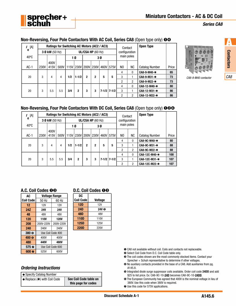
CA8-9-10 contactor
Ordering Instructions
Miniature Contactors - AC & DC Coil Series CA8
CA8 not available without coil. Coils and contacts not replaceable.Select Coil Code from D.C. Coil Code table only. The coil codes shown are the most commonly stocked items. Contact your Sprecher + Schuh representative to determine if special voltages, are required.
Integrated diode surge suppressor coils available. Order coil code 24DD and add $25 to list price. Ex: CA8-9C-10-24D becomes CA8-9C-10-24DD.
The European Community has agreed that 400V is the nominal voltage in lieu of 380V. Use this code when 380V is required.Use this code for 575V applications.
Non-Reversing, Three Pole Contactors With AC Coil, Series CA8 (Open type only)
A.C. Coil Codes
Non-Reversing, Three Pole Contactors With DC Coil, Series CA8 (Open type only)
D.C. Coil Codes
Ie
[A]
40ºC
Ratings for Switching AC Motors (AC2 / AC3 / AC4) Auxiliary Contacts per
Contactor
Open Type
Catalog Number Price
3 Ø kW (50 Hz) UL/CSA HP (60 Hz)
230V400V415V 500V
1 Ø 3 Ø
AC-1 115V 230V 200V 230V 460V 575V NO NC
20 3 4 4 1/2 1-1/2 2 2 5 51 0 CA8-9-10- 65
0 1 CA8-9-01- 65
20 3 5.5 5.5 3/4 2 3 3 7-1/2 7-1/21 0 CA8-12-10- 79
0 1 CA8-12-01- 79
ACCoil Code
Voltage Range50 Hz 60 Hz
12 12V 12V
24Z 24V 24V
48 48V 48V
120 110V 120V
208 200V-220V 200V-220V
240 240V 240V
380 Use Coil Code 400
400 400V 400V
480 440V 480V
575 Use Coil Code 600
600 525V 600V
Ie
[A]
40ºC
Ratings for Switching AC Motors (AC2 / AC3 / AC4) Auxiliary Contacts per
Contactor
Open Type
Catalog Number Price
3 Ø kW (50 Hz) UL/CSA HP (60 Hz)
230V400V415V 500V
1 Ø 3 Ø
AC-1 115V 230V 200V 230V 460V 575V NO NC
20 3 4 4 1/2 1-1/2 2 2 5 51 0 CA8-9C-10- 80
0 1 CA8-9C-01- 80
20 3 5.5 5.5 3/4 2 3 3 7-1/2 7-1/21 0 CA8-12C-10- 100
0 1 CA8-12C-01- 100
DCCoil Code Voltage
12D 12V
24D 24V
48D 48V
110D 110V
125D 125V
220D 220V
Specify Catalog NumberReplace ( ) with Coil Code See Coil Code table on
this page for codes
Contactors
CA8
Discount Schedule A-1
A
A145.6
Miniature Contactors - AC & DC Coil Series CA8
Non-Reversing, Four Pole Contactors With AC Coil, Series CA8 (Open type only)
Ordering Instructions
CA8 not available without coil. Coils and contacts not replaceable. Select Coil Code from D.C. Coil Code table only.The coil codes shown are the most commonly stocked items. Contact your Sprecher + Schuh representative to determine if other voltages.
No auxiliary contacts provided in the base of a CA8. Add auxiliaries from pg. A145.8.Integrated diode surge suppressor coils available. Order coil code 24DD and add $25 to list price. Ex: CA8-9C-10-24D becomes CA8-9C-10-24DD.
The European Community has agreed that 400V is the nominal voltage in lieu of 380V. Use this code when 380V is required.Use this code for 575V applications.
Specify Catalog NumberReplace ( ) with Coil Code See Coil Code table on
this page for codes
Ie
[A]
40ºC
Ratings for Switching AC Motors (AC2 / AC3) Contactconfiguration main poles
Open Type
Catalog Number Price
3 Ø kW (50 Hz) UL/CSA HP (60 Hz)
230V400V415V 500V
1 Ø 3 Ø
AC-1 115V 230V 200V 230V 460V 575V NO NC
20 3 4 4 1/2 1-1/2 2 2 5 5
4 0 CA8-9-M40- 65
3 1 CA8-9-M31- 73
2 2 CA8-9-M22- 73
20 3 5.5 5.5 3/4 2 3 3 7-1/2 7-1/2
4 0 CA8-12-M40- 80
3 1 CA8-12-M31- 86
2 2 CA8-12-M22- 86
Non-Reversing, Four Pole Contactors With DC Coil, Series CA8 (Open type only)
Ie
[A]
40ºC
Ratings for Switching AC Motors (AC2 / AC3) Contactconfiguration main poles
Open Type
Catalog Number Price
3 Ø kW (50 Hz) UL/CSA HP (60 Hz)
230V400V415V 500V
1 Ø 3 Ø
AC-1 115V 230V 200V 230V 460V 575V NO NC
20 3 4 4 1/2 1-1/2 2 2 5 5
4 0 CA8-9C-M40- 80
3 1 CA8-9C-M31- 88
2 2 CA8-9C-M22- 88
20 3 5.5 5.5 3/4 2 3 3 7-1/2 7-1/2
4 0 CA8-12C-M40- 100
3 1 CA8-12C-M31- 107
2 2 CA8-12C-M22- 107
CA8-9-M40 contactor
A.C. Coil Codes D.C. Coil Codes DC
Coil Code Voltage12D 12V
24D 24V
48D 48V
110D 110V
125D 125V
220D 220V
ACCoil Code
Voltage Range50 Hz 60 Hz
12 12V 12V
24Z 24V 24V
48 48V 48V
120 110V 120V
208 200V-220V 200V-220V
240 240V 240V
380 Use Coil Code 400
400 400V 400V
480 440V 480V
575 Use Coil Code 600
600 525V 600V

Discount Schedule A-1A145.7
Cont
acto
rs
CA8
A Reversing, Three Pole Contactors With AC Coil, Series CAU8 (Open type only)
CAU8…LW Includes:
CAU8…PW Includes:
interlock
wiring (using Wiring Kit Cat.# CAUT8-PW)
block (Cat.# CA8-P20 on the -42- models)
Miniature Contactors – Reversing Series CAU8
Ordering Instructions
CA8 not available without coil. Coils and contacts not replaceable. Internal NC contacts on each contactor are used for electrical interlocking.The coil codes shown are the most commonly stocked items. Contact your Sprecher + Schuh representative to determine if other voltages are required.Integrated diode surge suppressor coils available. Order coil code 24DD and add $50 to list price. Ex: CAU8-9C-02-24D becomes CAU8-9C-02-24DD.
The European Community has agreed that 400V is the nominal voltage in lieu of 380V. Use this code when 380V is required.Use this code for 575V applications.
Specify Catalog NumberReplace ( ) with Coil Code See Coil Code table on
this page for codes
Ie
[A]
40ºC
Ratings for Switching AC Motors (AC2 / AC3 / AC4) Auxiliary Contacts per
Contactor
Open Type
Catalog Number Price
3 Ø kW (50 Hz) UL/CSA HP (60 Hz)
230V400V415V 500V
1 Ø 3 Ø
AC-1 115V 230V 200V 230V 460V 575V NO NC
20 3 4 4 1/2 1-1/2 2 2 5 50 1 CAU8-9-02- -LW 151
2 1 CAU8-9-42- -PW 176
20 3 5.5 5.5 3/4 2 3 3 7-1/2 7-1/20 1 CAU8-12-02- -LW 199
2 1 CAU8-12-42- -PW 215
Reversing, Three Pole Contactors With DC Coil, Series CAU8 (Open type only)
Ie
[A]
40ºC
Ratings for Switching AC Motors (AC2 / AC3 / AC4) Auxiliary Contacts per
Contactor
Open Type
Catalog Number Price
3 Ø kW (50 Hz) UL/CSA HP (60 Hz)
230V400V415V 500V
1 Ø 3 Ø
AC-1 115V 230V 200V 230V 460V 575V NO NC
20 3 4 4 1/2 1-1/2 2 2 5 50 1 CAU8-9C-02- -LW 201
2 1 CAU8-9C-42- -PW 226
20 3 5.5 5.5 3/4 2 3 3 7-1/2 7-1/20 1 CAU8-12C-02- -LW 250
2 1 CAU8-12C-42- -PW 275
A.C. Coil Codes D.C. Coil Codes DC
Coil Code Voltage12D 12V
24D 24V
48D 48V
110D 110V
125D 125V
220D 220V
ACCoil Code
Voltage Range50 Hz 60 Hz
12 12V 12V
24Z 24V 24V
48 48V 48V
120 110V 120V
208 200V-220V 200V-220V
240 240V 240V
380 Use Coil Code 400
400 400V 400V
480 440V 480V
575 Use Coil Code 600
600 525V 600V

Contactors
CA8
Discount Schedule A-1
A
A145.8
Non-Reversing, Three Pole Starters With AC Coil, Series CAT8 (Open type only)
Miniature Starters, AC & DC Coil Series CAT8
Ordering Instructions
Non-Reversing, Three Pole Starters With DC Coil, Series CAT8 (Open type only)
CA8 not available without coil. Coils and contacts not replaceable. Select Coil Code from D.C. Coil Code table only.The coil codes shown are the most commonly stocked items. Contact your Sprecher + Schuh representative to determine if other voltages are required.Integrated diode surge suppressor coils available. Order coil code 24DD and add $25 to list price. Ex: CAT8-9C-10-24D becomes CAT8-9C-10-24DD.
The European Community has agreed that 400V is the nominal voltage in lieu of 380V. Use this code when 380V is required.Use this code for 575V applications.
Representative model of a CAT8-9… starter with the CT8 bimetallic
overload relay
NOTE: CAT8 starters are priced to include Sprecher + Schuh’s economical CT8 bimetallic overload relay. See page A145.10 for selection.
Ie
[A]
40ºC
Ratings for Switching AC Motors (AC2 / AC3 / AC4) Auxiliary Contacts per
Contactor
Open Type
Catalog Number Price
3 Ø kW (50 Hz) UL/CSA HP (60 Hz)
230V400V415V 500V
1 Ø 3 Ø
AC-1 115V 230V 200V 230V 460V 575V NO NC
20 3 4 4 1/2 1-1/2 2 2 5 51 0 CAT8-9-10- - 107
0 1 CAT8-9-01- - 107
20 3 5.5 5.5 3/4 2 3 3 7-1/2 7-1/21 0 CAT8-12-10- - 125
0 1 CAT8-12-01- - 125
Ie
[A]
40ºC
Ratings for Switching AC Motors (AC2 / AC3 / AC4) Auxiliary Contacts per
Contactor
Open Type
Catalog Number Price
3 Ø kW (50 Hz) UL/CSA HP (60 Hz)
230V400V415V 500V
1 Ø 3 Ø
AC-1 115V 230V 200V 230V 460V 575V NO NC
20 3 4 4 1/2 1-1/2 2 2 5 51 0 CAT8-9C-10- - 122
0 1 CAT8-9C-01- - 122
20 3 5.5 5.5 3/4 2 3 3 7-1/2 7-1/21 0 CAT8-12C-10- - 146
0 1 CAT8-12C-01- - 146
Specify Catalog Number
Replace ( ) with Coil CodeReplace ( ) with O/L Relay Code
Coil Codes on this page O/L Relay Code on A145.12
A.C. Coil Codes D.C. Coil Codes DC
Coil Code Voltage12D 12V
24D 24V
48D 48V
110D 110V
125D 125V
220D 220V
ACCoil Code
Voltage Range50 Hz 60 Hz
12 12V 12V
24Z 24V 24V
48 48V 48V
120 110V 120V
208 200V-220V 200V-220V
240 240V 240V
380 Use Coil Code 400
400 400V 400V
480 440V 480V
575 Use Coil Code 600
600 525V 600V

Discount Schedule A-1A145.9
Cont
acto
rs
CA8
A Reversing, Three Pole Starters With AC Coil, Series CAUT8 (Open type only)
CAUT8…LW Includes:
overload relay. Select code from page A145.10.
CAUT8…PW Includes:
electrical interlock
overload relay. Select code from page A145.10.
wiring (using Wiring Kit Cat.#CAUT8-PW)
block (Cat.# CA8-P20 on the -42- models)
Miniature Starters, AC and DC Coil – Reversing Series CAUT8
Ordering Instructions
CA8 not available without coil. Coils and contacts not replaceable. NC contacts on each contactor are used for electrical interlocking. The coil codes shown are the most commonly stocked items. Contact your Sprecher + Schuh representative to determine if other voltages are required.Integrated diode surge suppressor coils available. Order coil code 24DD and add $50 to list price. Ex: CAUT8-9C-02-24D becomes CAUT8-9C-02-24DD.
The European Community has agreed that 400V is the nominal voltage in lieu of 380V. Use this code when 380V is required.Use this code for 575V applications.
Ie
[A]
40ºC
Ratings for Switching AC Motors (AC2 / AC3 / AC4) Auxiliary Contacts per
Contactor
Open Type
Catalog Number Price
3 Ø kW (50 Hz) UL/CSA HP (60 Hz)
230V400V415V 500V
1 Ø 3 Ø
AC-1 115V 230V 200V 230V 460V 575V NO NC
20 3 4 4 1/2 1-1/2 2 2 5 50 1 CAUT8-9-02- - -LW 193
2 1 CAUT8-9-42- - -PW 218
20 3 5.5 5.5 3/4 2 3 3 7-1/2 7-1/20 1 CAUT8-12-02- - -LW 236
2 1 CAUT8-12-42- - -PW 261
Specify Catalog Number
Replace ( ) with Coil CodeReplace ( ) with O/L Relay Code
Coil Codes on this page O/L Relay Code on A145.12
Reversing, Three Pole Starters With DC Coil, Series CAUT8 (Open type only)
Ie
[A]
40ºC
Ratings for Switching AC Motors (AC2 / AC3 / AC4) Auxiliary Contacts per
Contactor
Open Type
Catalog Number Price
3 Ø kW (50 Hz) UL/CSA HP (60 Hz)
230V400V415V 500V
1 Ø 3 Ø
AC-1 115V 230V 200V 230V 460V 575V NO NC
20 3 4 4 1/2 1-1/2 2 2 5 50 1 CAUT8-9C-02- - -LW 247
2 1 CAUT8-9C-42- - -PW 272
20 3 5.5 5.5 3/4 2 3 3 7-1/2 7-1/20 1 CAUT8-12C-02- - -LW 296
2 1 CAUT8-12C-42- - -PW 321
A.C. Coil Codes D.C. Coil Codes DC
Coil Code Voltage12D 12V
24D 24V
48D 48V
110D 110V
125D 125V
220D 220V
ACCoil Code
Voltage Range50 Hz 60 Hz
12 12V 12V
24Z 24V 24V
48 48V 48V
120 110V 120V
208 200V-220V 200V-220V
240 240V 240V
380 Use Coil Code 400
400 400V 400V
480 440V 480V
575 Use Coil Code 600
600 525V 600V

ContactorsContactors
CA8
Discount Schedule A-1
AAA
A145.10
AuxiliaryContact Blocks NO NC
ContactArrangement Catalog No. Price
2-Pole
Typical auxiliarycontact block
4-Pole
1 1 CS8-P11E
160 2 CS8-P02E
2 0 CS8-P20E
2 2 CS8-P22Z
32
3 1 CS8-P31Z
1 3 CS8-P13E
0 4 CS8-P04E
4 0 CS8-P40E
Auxiliary Contact Blocks (2 & 4 Pole)
Control Modules
Module DescriptionFor usewith...
ConnectionDiagrams Function Catalog Number Price
Pluggable electronic timer –ON-DelayThe contactor is energized at theend of the delay time.
CA8 all
110...250V 50/60Hz0.1...3 sec1...30 sec
CRZE8-3-110/240 CRZE8-30-110/240
60
24...48VDC0.1...3 sec1...30 sec
CRZE8-3-24/48VDC CRZE8-30-24/48VDC
Pluggable electronic timer –OFF-DelayThe timer switches off after the settime has elapsed
CA8 all
110...250V 50/60Hz1...30 sec CRZA8-30-110/240
60
24...48VDC1...30 sec CRZA8-30-24/48VDC
AuxiliaryContact Blocks NO NC
ContactArrangement Catalog No. Price
2-Pole
Typical auxiliarycontact block
4-Pole
1 1 CA8-P11
160 2 CA8-P02
2 0 CA8-P20
2 2 CA8-P22
32
3 1 CA8-P31
1 3 CA8-P13
0 4 CA8-P04
4 0 CA8-P40
Auxiliary contacts mirror contact performance per IEC 60947-4-1. Contacts are bifurcated (H-bridge) with a minimum rating of 2mA @ 15V.
Accessories - Field InstallableCA8 Miniature Contactors & Starters

Discount Schedule A-1A145.11
Cont
acto
rs
CA8
A
Accessories - Field InstallableCA8 Miniature Contactors & Starters
Miscellaneous Accessories
CA8 contactors with 24 VDC coils can be special ordered with integrated diodes (built-in) rather than applying CRD8 to the coil terminals.
Accessory Description Catalog Number Price
Surge Suppressor CR__8 - for limiting voltage spikes when switching off coil. Coil itself provides sufficient limitation at voltages over 240V.
RC Link (Type CRC8…) for AC Control24-48VAC110-280VAC380-480VAC
Diode Link (Type CRD8…) for DC Control 12-250VDC (diode)
Varistor Link (Type CRV8…)for AC/DC Control12-55VAC/12-77VDC56-136VAC/78-180VDC137-277VAC/181-250VDC
CRC8-50CRC8-280CRC8-480
CRD8-250
CRV8-55CRV8-136CRV8-277
20
20
13
Mechanical Interlock Kit -For interlocking of two adjacent contactor – without additional space requirement in width– attachable from the front (top) of contactor– optional auxiliary contact blocks can be mounted on
the top (does not interfere with mounting CR__8)
CM8 7
Wiring Kit -For connecting line, load and control wiring of a CAU8 reversing contactor.– works with CT8 Overloads
CAUT8-PW 9
Connection Modules -For KTA7 motor circuit controller with a CA8 contactor.
KT7-25S-PEK12 24
Feeder Terminal for Compact Bus Bars - Supply of compact bus bars. For use with CA8-9 and12.
CA8-WT 25
Three-Phase Compact Bus Bars -For use with CA8-9 and 12 Contactors with 45 mm spacing. (3 connections)
CA8-W453 30
Three-Phase Compact Bus Bars -For use with CA8-9 and 12 Contactors with 45 mm spacing. (4 connections)
CA8-W454 35
Contactors
CA8
Discount Schedule A-1
A
A145.12
Overload Relay CodesSeries CA8 Starters
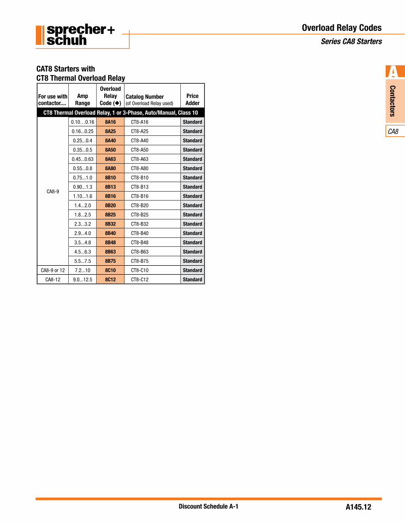
CAT8 Starters withCT8 Thermal Overload Relay
For use with contactor....
AmpRange
OverloadRelay
Code ( )Catalog Number(of Overload Relay used)
PriceAdder
CT8 Thermal Overload Relay, 1 or 3-Phase, Auto/Manual, Class 10
CA8-9
0.10…0.16 8A16 CT8-A16 Standard
0.16...0.25 8A25 CT8-A25 Standard
0.25...0.4 8A40 CT8-A40 Standard
0.35...0.5 8A50 CT8-A50 Standard
0.45...0.63 8A63 CT8-A63 Standard
0.55...0.8 8A80 CT8-A80 Standard
0.75...1.0 8B10 CT8-B10 Standard
0.90...1.3 8B13 CT8-B13 Standard
1.10...1.6 8B16 CT8-B16 Standard
1.4...2.0 8B20 CT8-B20 Standard
1.8...2.5 8B25 CT8-B25 Standard
2.3...3.2 8B32 CT8-B32 Standard
2.9...4.0 8B40 CT8-B40 Standard
3.5...4.8 8B48 CT8-B48 Standard
4.5...6.3 8B63 CT8-B63 Standard
5.5...7.5 8B75 CT8-B75 Standard
CA8-9 or 12 7.2...10 8C10 CT8-C10 Standard
CA8-12 9.0...12.5 8C12 CT8-C12 Standard

Discount Schedule A-1A145.13
Cont
acto
rs
CA8
A
Technical InformationCA8 Miniature Contactors
Technical Information
CA8-9 CA8-12
Rated Insulation Voltage Uito IEC947-1 [V] 690VUL/CSA [V] 600V
Rated Impulse Voltage Withstand Uimp
[kV] 6
Rated Voltage Ue-Main ContactsAC 50/60Hz [V] 230, 240, 400, 415, 500, 690DC [V] 24, 48, 110, 220, 440
Operating Frequency for AC Loads [Hz] 50/60Hz
Switching Motor LoadsStandard IEC RatingsAC-2, AC-3, AC-4 230V [A] 11.3 11.3
DOL & Reversing 240V [A] 11.3 11.350Hz@60˚ C 400V [A] 8.5 11.5
415V [A] 8.5 11.5500V [A] 6.8 9.2690V [A] 4.9 6.7230V [kW] 3 3240V [kW] 3 3400V [kW] 4 5.5415V [kW] 4 5.5500V [kW] 4 5.5690V [kW] 4 5.5
UL/CSA 115V [A] 9.8 13.8DOL & Reversing 1 230V [A] 10 1260Hz 115V [HP] 0.5 0.75
230V [HP] 1.5 2200V [A] 7.8 11230V [A] 6.8 9.6460 V [A] 7.6 11
3 575 V [A] 6.1 9200 V [HP] 2 3230 V [HP] 2 3460 V [HP] 5 7.5575 V [HP] 5 7.5
Maximum Operating Rate AC2 [ops/hour] 300 300At 9A for AC3; 20A for AC2/4 AC3 [ops/hour] 600 600Starting time tA = 0.25s AC4 [ops/hour] 300 300
AC4 (200,000 Op. Cycles) 230V [A] 3.9 3.9 50Hz 240V [A] 3.9 3.9
400V [A] 3.6 3.6415V [A] 3.6 3.6500V [A] 3.2 3.2230V [kW] 0.75 0.75240V [kW] 0.75 0.75400V [kW] 1.5 1.5415V [kW] 1.5 1.5500V [kW] 1.5 1.5
Max. Operating Rate [ops/hour] 250 250
CA8-9 CA8-12
Wye-Delta (Star Delta) 230V [A] 20 2050 Hz 240V [A] 20 20
400V [A] 15.5 15.5415V [A] 15.5 15.5500V [A] 12.4 12.4690V [A] 8.9 8.9230V [kW] 5.5 5.5240V [kW] 5.5 5.5400V [kW] 7.5 7.5415V [kW] 7.5 7.5500V [kW] 7.5 7.5690V [kW] 7.5 7.5
60 Hz 200V [Hp] 3.3 5230V [Hp] 3.3 5460V [Hp] 8.5 12575V [Hp] 8.5 12
AC-1 Load, 3 SwitchingAmbient Temperature 40˚ C Ie [A] 20 20
230V [kW] 8 8240V [kW] 8.3 8.3400V [kW] 14 14415V [kW] 14 14500V [kW] 17 17690V [kW] 24 24
Ambient Temperature 60˚ C Ie [A] 16 16230V [kW] 6.4 6.4240V [kW] 6.7 6.7400V [kW] 11 11415V [kW] 12 12500V [kW] 14 14690V [kW] 19 19
Continuous Current (UL/CSA)General Purpose Rating (40˚ C) Open [A] 12 12
Enclosed [A] 15 18
Lighting LoadsGas Dischrg.Lamps-AC-5a, 220…240VAC (40ºC)
Enclosed [A] 18 18Open [A] 14.5 14.5
Single compensated Max. capacitance at prospective short circuitcurrent available at the contactor
10kA F] 750 75020kA F] 400 40050kA F] ~ ~
Incandescent Lamps - AC-5bElectrical endurance~100,000 operations 230/240V [A] 9.0 9.0

Contactors
CA8
Discount Schedule A-1
A
A145.14
Electrical Data
Technical InformationCA8 Miniature Contactors
CA8-9 CA8-12
Switching power transformers AC-6a (50Hz)Inrush =
Rated transformer current = 30 230V [A] 5.4 5.4
240V [A] 5.4 5.4400V [A] 4.1 5.4415V [A] 4.1 5.4500V [A] 3.2 3.2
230VAC [kVA] 2 2240VAC [kVA] 2 2400VAC [kVA] 2.8 3.4415VAC [kVA] 2.8 3.4500VAC [kVA] 2.8 3.4690VAC [kVA] 4 5
DC RatingsDC-1 Rating at 60°C
1 Pole 24VDC [A] 9 948/60VDC [A] 6/1.5 6/1.5110VDC [A] 1 1220VDC [A] 0.3 0.3440VDC [A] 0.1 0.1
2 Pole in Series 24VDC [A] 9 948/60VDC [A] 8 8110VDC [A] 6 6220VDC [A] 1.2 1.2440VDC [A] 0.3 0.3
3 Pole in Series 24VDC [A] 9 948VDC [A] 9 9110VDC [A] 9 9220VDC [A] 4 4440VDC [A] 0.6 0.6
Shunt-wound MotorsStarting, reverse current braking, reversing stepping DC-3, 60°C
24V [A] 9 93 Poles in series 48/60V [A] 6 6
110V [A] 3 3220V [A] 1.2 1.2440V [A] 0.2 0.2
Series-wound MotorsStarting, reverse current braking, reversing stepping DC-5, 60°C
24V [A] 9 93 poles in series 48/60V [A] 3 3
110V [A] 1 1220V [A] 0.1 0.1440V [A] ~ ~
Short Time Withstand-ICW, 60°C10s [A] 96 96
UL listed combination.
Coil DataCA8-9 CA8-12
Voltage RangeAC: 50Hz, 60Hz, 50/60 Hz Pickup [x Us] 0.85...1.1
Dropout [x Us] 0.2…0.75DC Pickup [x Us] 0.8...1.1
9, 12, 24, 110V DC: 0.7…1.25Dropout [x Us] 0.1...0.75
Coil ConsumptionAC: 50Hz, 60Hz, 50/60 Hz Pickup [VA/W] 35/32
Hold-in [VA/W] 5/1.8DC Pickup [W] cold 3.0, warm 2.6
Hold-in [W] cold 3.0, warm 2.6Operating Times
AC: 50Hz, 60Hz, 50/60 Hz Pickup [ms] 15...40Dropout [ms] 15...33
with RC Suppressor Dropout [ms] 15...28DC Pickup [ms] 18...40
Dropout [ms] 6...12
with Integ. Suppression Dropout [ms] 8...12
with external diodeSuppression
Dropout [ms] 35...50
Minimal changeover time for reversing [ms] >50
Short Circuit Coordination(Max. Fuse or Circuit Breaker Rating) CA8-9 CA8-12
50 kA Max. DIN fuse gG per IEC 60947-4-1 (Contactor and Fuse only)Available Fault CurrentType 1 Coordination (690V) max. [A] 35 35Type 2 Coordination (690V) max. [A] 20 20Class K5 and RK5 fuses max. [A] 40 40
Resistance and Watt Loss le AC3Resistance per power pole [m ] 2.2 2.2Watt Loss - 3 power poles @400V [W] 0.9 0.9Coil and AC @400V, warm [W] 2.7 2.73 power poles DC, warm [W] 3.5 3.5

Discount Schedule A-1A145.15
Cont
acto
rs
CA8
A Mechanical Data
Technical InformationCA8 Miniature Contactors
CA8-9 CA8-12
Service Life
Mechanical AC [Mil.Op.] 15Electrical AC-3(400V) [Mil.Op.] 0.7Reversing combination, mechanical, electrical
[Mil.Op.] 0.7
Shipping WeightsAC-CA8 [kg] 0.16
[Lbs] 0.35AC-CAU8 [kg] 0.35
[Lbs] 0.77DC-CA8 [kg] 0.20
[Lbs] 0.44DC-CAU8 [kg] 0.43
[Lbs] 0.91
Terminations - Screw Type TerminalsMain contacts and Auxiliary contacts
Terminal Type Combination Screw Head: Cross, Slotted, PozidriveFine stranded w/ ferrule
1 wire2 wires
[mm2][mm2]
0.75...2.50.75...2.5
Solid or coarsestranded
1 wire2 wires
[mm2][mm2]
1…40.75...2.5 + 1…4
[AWG] 18…12
Torque Requirement [Nm] 1.2[Lb-in] 10.6
Environmental and General Specifications
Ambient TemperatureStorage -55...+80˚ C (-67...176˚ F)Operation -25...+60˚ C (-13...140˚ F)Conditioned 15% current -25...+70˚ C (-13...158˚ F)reduction after AC-1 at >60˚ C
Altitude at installed site 2000 meters above sea level per IEC 60947-4-1
Resistance to Corrosion / Humidity
Damp-alternating climate: cyclic to IEC 68-2, 56 cycles.
Dry Heat: IEC 68-2, +100°C (212°F), relative humidity <50%, 7 days.
Damp tropical: IEC 68-2, +40°C (104°F), relative humidity <92%, 56 days.
Shock Resistance IEC 68-2/EN 60068
Vibration Resistance IEC 68-2/EN 60068
Operating Position Refer to Dimension Pages
Standards IEC/EN 60947-1, -4-1, -5-1, -5-4; UL 508; CSA 22.2. No. 14
Approvals

Contactors
CA8
Discount Schedule A-1
A
A145.16
Technical InformationCA8 Miniature Contactors
Auxiliary ContactsBuilt-in Auxiliary Contacts Add-on Auxiliary Contacts
Current SwitchingAC-12 Ith at 40°C [A] 10 10
at 60°C [A] 6 6AC-15, switching electromagnetic loads at: [V] 24 120 240 400 480 500 600 690 24 120 240 400 480 500 600 690
[A] 6 6 3 1.8 1.5 1.4 1.2 1 3 3 2 1.2 1 1 0.6 0.6DC-13, switching DC electromagnets at: [V] 24 48 110 125 220 250 400 440 600 24 48 110 125 220 250 400 440 600
[A] 2.8 1.2 0.55 0.55 0.27 0.27 0.15 0.15 0.10 2.3 1 0.55 0.55 0.27 0.27 0.15 0.15 0.10DC-12, L/R< 1 ms resistive loads at: [V] 24 48 110 125 220 250 400 440
[A] 6 4 0.6 0.6 0.2 0.2 0.08 0.08
DC-14, L/R< 15 ms inductive loads with economy resistor in series at:
[V] 24 48 110 125 220 250 400 440[A] 4 2.5 0.4 0.4 0.12 0.12 0.05 0.05
Low Level Signal SwitchingContact design X-stamped H-bridge, bi-furcatedMinimum switching recommendation [V] 17V 15V
[mA] 10mA 2mAShort-Circuit Protection - gG Fuse
Type 2 Coordination [A] 10 10Load carrying capacity per UL/CSA
Rated Voltage AC [V] 600 max. 600 max.Continuous Rating 40°C [A] 10 general purpose 10 general purposeSwitching Capacity AC Heavy pilot duty (A600) Heavy pilot duty (B600)Rated Voltage DC [V] 600 max. 600 max.Switching Capacity DC Standard pilot duty (Q600) Standard pilot duty (Q600)Mechanically Linked ContactsIEC 60947-5-1, Annex L
Yes No
Mirror Contacts IEC 60947-4, Annex F
Yes Yes
Contact Ratings (Per NEMA/UL A600, B600 & Q600)
StandardCircuitVoltage
Make(Amps/VA)
Break(Amps/VA)
ContinuousAmps
A600
120AC240AC480AC600AC
60A/7200VA30A/7200VA15A/7200VA12A/7200VA
60A/720VA30A/720VA15A/720VA12A/720VA
10
B600
120AC240AC480AC600AC
30A/3600VA15A/3600VA7.5A/3600VA6A/3600VA
3.0A/360VA1.5A/360VA0.75A/360VA0.60A/360VA
10
Q600125DC250DC
301-600DC
0.55/69VA0.27/69VA0.1A/69VA
0.55/69VA0.27/69VA0.1A/69VA
2.5

Discount Schedule A-1A145.17
Cont
acto
rs
CA8
A
Technical InformationCA8 Miniature Contactors
Determining Contact LifeTo determine the contactor’s estimated electrical life, follow these guidelines:1. Identify the appropriate Utilization Category from Table A.2. On the following pages, choose the graph for the Utilization Cat-
egory selected.
Table A – IEC Special Utilization Categories, AC Ratings
Utilization categories and test conditions for AC & DC. For contactors according to IEC 158-1, starters according to IEC 292-1 ... 4 and control switches according to IEC 337-1 and IEC 337-1A.With a minimum value of 1000A for I or Ic.With a minimum value of 800A for Ic.With a minimum value of 1200A for I.Plugging is understood as stopping or reversing the motor rapidly by reversing the motor primary connections while the motor is running. Inching [or jogging] is understood as energizing a motor once or repeatedly for short periods to obtain small movements of the driven mechanism.
3. Locate the Rated Operational Current (le) along the bottom of the chart and follow the graph lines up to the intersection of the ap-propriate contactor’s life-load curve.
4. Read the estimated contact life along the vertical axis.
LegendUe Rated operational voltageU Voltage before makeUr Recovery voltageIe Rated operational currentI Making currentIc Breaking currentL Inductance of test circuitR Resistance of test circuit
Category Typical Applications Rated Current
Conditions for testingelectrical life
Ops.
Conditions for testing making and breaking capacity
Ops.Make Break Make Break
I/Ie U/Ue cos Ic/Ie Ur/Ue cos I/Ie U/Ue cos Ic/Ie Ur/Ue cos
CONT
ACTO
RS
AC-1Non-inductive or slightlyinductive loads, resistance furnaces
All values 1 1 0.95 1 1 0.95 6000 1.5 1.05 0.8 1.5 1.05 0.8 50
AC-2Slip-ring motors:Starting, plugging
All values 2 1.05 0.65 2 1.05 0.65 6000 4 1.05 0.65 4 1.05 0.65 50
AC-3Squirrel-cage motors:Starting, switching off motors during running
Ie 17Amp17Amp<Ie 100Amp Ie>100Amp
666
111
0.650.350.35
111
0.170.170.17
0.650.350.35
60001010
8
1.11.11.1
0.650.350.35
88
6
1.11.11.1
0.650.350.35
50
AC-4Squirrel-cage motors:Starting, plugging, inching
Ie 17Amp17Amp<Ie 100Amp Ie>100Amp
666
111
0.650.350.35
666
111
0.650.350.35
60001212
10
1.11.11.1
0.650.350.35
1010
8
1.11.11.1
0.650.350.35
50
AC-5aSwitching of electric discharge lamp control
2 1.05 0.45 2 1.05 0.45 6000 3 1.05 0.45 3 1.05 0.45 50
AC-5b Switching of incandescent lamps 1 1.05 1 1.05 1.5 1.05 1.5 1.05 50AC-6a Switching of transformers Rating derived from AC-3 rating (x 0.45)AC-6b Switching of capacity banks Depends on circuit conditions of application
AC-12Control of resistive loads and solid state loads with isolationby opto couplers
All values 1 1 0.9 1 1 0.9 6050
CONT
ROL
DEVI
CES AC-13
Control of solid state loads with transformer isolation
2 1 0.65 1 1 0.65 6050 10 1.1 0.65 1.1 1.1 0.65 10
AC-14Control of small electromagnetic loads
72 VA 6 1 0.3 1 1 0.3 6050 6 1.1 0.7 6 1.1 0.7 10
AC-15 Control of electromagnetic loads 72 VA 10 1 0.3 1 1 0.3 6050 10 1.1 0.3 10 1.1 0.3 10
AC-20Connecting and disconnecting under no load conditions
No testing required
SWIT
CHES
AC-21Switching of resistive loads, including moderate loads
All values 1 1 0.95 1 1 0.95 10000 1.5 1.05 0.95 1.5 1.05 0.95 5
AC-22Switching of mixed resistive & inductive loads, includingmoderate overloads
All values 1 1 0.8 1 1 0.8 10000 3 1.05 0.65 3 1.05 0.65 5
AC-23Switching of motor loads or other highly inductive loads
All values 1 1 0.65 1 1 0.65 10000 10 1.05 0.45 8 1.05 0.45 5

Contactors
CA8
Discount Schedule A-1
A
A145.18
Technical InformationCA8 Contactors - Contact Life
Table A – IEC Special Utilization Categories, DC Ratings
Utilization categories and test conditions for AC & DC. For contactors according to IEC 158-1, starters according to IEC 60292-1 ... 4 and control switches according to IEC 337-1 and IEC 337-1A.Only according to VDE.P = Ue x Ie rated power [W]. The value “6 x P” has been derived from an empiric relationship which covers most magnetic loads for DC up to an upper limit of P = 50W.
Determining Contact LifeTo determine the contactor’s estimated electrical life, follow these guidelines:1. Identify the appropriate Utilization Category from Table A.2. On the following pages, choose the graph for the Utilization
Category selected.
3. Locate the Rated Operational Current (le) along the bottom ofthe chart and follow the graph lines up to the intersection of the appropriate contactor’s life-load curve.
4. Read the estimated contact life along the vertical axis.
LegendUe Rated operational voltageU Voltage before makeUr Recovery voltageIe Rated operational currentI Making currentIc Breaking currentL Inductance of test circuitR Resistance of test circuit
Conditions for testingelectrical life
Conditions for testing making and breaking capacity
Category Typical Applications Rated Current Make Break Ops Make Break Ops
I/Ie U/Ue cos Ic/Ie Ur/Ue cos I/Ie U/Ue cos Ic/Ie Ur/Ue cos
DC-1Non-inductive or slightly inductive loads, resistance furnaces
All values 1 1 1 1 1 1 1.5 1.1 1 1.5 1.1 1
DC-2Shunt-motors:Starting, switching off motors during running
All values 2.5 1 2 1 0.1 7.5 4 1.1 2.5 4 1.1 2.5
DC-3Shunt-motors:Starting, plugging, inching
All values 2.5 1 2 2.5 1 2 4 1.1 2.5 4 1.1 2.5
DC-4Series-motors:Starting switching off motors during running
All values 2.5 1 7.5 1 0.3 10 4 1.1 15 4 1.1 15
DC-5Series-motors:Starting, plugging, inching
All values 2.5 1 7.5 2.5 1 7.5 4 1.1 15 4 1.1 15
DC-15Electromagnets for contactors, valves, solenoid actuators
All values 1 1 6 x P 1 1 6 x P 1.1 1.1 6 x P 1.1 1.1 6 x P

Discount Schedule A-1A145.19
Cont
acto
rs
CA8
A
Technical InformationCA8 Miniature Contactors – Life Load Curves
NOTE: The life-load curves shown here are based on Sprecher+Schuh tests according to the requirements defined in IEC 60947-4-1. Since contact life in any given application is dependent on environmental conditions and duty cycle, actual application contact life may vary from that indicated by the curves shown here.
Current (le) along the bottom of the chart and follow the graph lines up to the intersection of the appropriate contactor’s life-load curve.
along the vertical axis.
Life-Load Curves
AC-1, AC3(400...460V AC)
AC-4(400...460V AC)
INSTRUCTIONS ON“HOW TO READ”
LIFE CURVES CAN BEFOUND ON PG. A57.

Contactors
CA8
Discount Schedule A-1
A
A145.20
DimensionsCA8 Miniature Contactors
Series CA8 & Series CAU8 (Contactors & Reversing Contactors)

Discount Schedule A-1A145.21
Cont
acto
rs
CA8
A Notes
Miniature Contactors Series CA8

Motor
Motor
ProtectionProtection
CT8
BBB
B32.1Discount Schedule A-1
Series CT8 Thermal OverloadThermal OverloadThermal OverloadRelays
Simple and effectivemotor protectionfor applications to71/2HP@ 460V(10HP@575V)
Sprecher + Schuh has been a leader inproviding superior motor protection.The new CT8 is an economical ther-mal overload relay yet includes provenfeatures like “Differential tripping”,Automatic / Manual reset modes,and isolated alarm circuit contacts asstandards.
Consistent and reliableprotectionThe consistent high quality of Sprecher + Schuh thermal overloadrelays is ensured by a complex currentcalibration procedure performed aftereach unit is at full operating tempera-ture. Calibration is performed at thelargest and smallest current the over-load can handle. The accurate time/current characteristic curve obtained inthis manner guarantees reliable motorprotection every time.
Superior Class 10characteristicsToday’s T-Frame motors have lesscopper and iron that the old U-Framemotors that were popular whentraditional Class 20 overload relayswere designed. For this reason, fasterClass 10 overloads like the CT8 Serieshave been recognized by many motormanufacturers as the ideal type to assure optimum protection of “T”frame motors.
Protection from singlephase conditionsA unique feature not found in tradi-tional thermal overload relays providesaccelerated tripping under single phaseconditions. This is accomplished witha special “differential tripping” mecha-nism built into CT8 (see illustration atright).
Ambient temperaturecompensationAll Sprecher + Schuh thermal overloadrelays are temperature compensated.An additional bimetallic ambient com-pensation strip, built into the conduc-tor-bimetal transmission path, ensuresthat the tripping characteristics of therelay remain constant over an ambienttemperature range of –25°C to +50°C.
Single phase applicationsCT8 Series thermal overload relayscan be applied for protection of singlephase AC motors. The relays have thesame characteristics as shown for threephase operation. To maintain thesecharacteristics, each element of theoverload relay must carry the motorcurrent as shown in the schematic onpage C88.
Other standard featuresCT8 thermal overload relays feature a fail-safe “trip-free” design that preventsthe device from being held closed dur-ing an overload. In addition, a select-able lever permits the user the optionto choose the manual or automaticreset modes.
A separate NO signal contact is alsoprovided on CT8 overloads which isisolated from the NC trip contact.This permits the use of a trip signalvoltage different than that of the con-trol voltage.
CT8 Thermal Overload Relays offer accelerated tripping under single phase conditions
Sprecher + Schuh provides outstanding motor protection with our CT8 Thermal Overload Relay

Mot
orM
otor
Prot
ectio
nPr
otec
tion
CT8
BBB
B32.2 Discount Schedule A-1
Overload RelayDirectly Mountsto Contactor...
AdjustmentRanges [A]
Trip Class 10
Catalog Number Price
CA8-9
0.10…0.16 CT8-A16
42
0.16…0.25 CT8-A250.25…0.4 CT8-A400.35… 0.5 CT8-A500.45…0.63 CT8-A630.55…0.80 CT8-A800.75…1.0 CT8-B100.90…1.3 CT8-B131.10…1.6 CT8-B161.4…2.0 CT8-B201.8…2.5 CT8-B252.3…3.2 CT8-B322.9…4.0 CT8-B403.5...4.8 CT8-B484.5…6.3 CT8-B635.5…7.5 CT8-B75
CA8-9 or 12 7.2...10 CT8-C10 46
CA8-12 9.0...12.5 CT8-C12 46
CT8 Thermal Overload Relays - manual or automatic reset
Thermal Overload RelaysSeries CT8
Accessories Description For Use with... Catalog NumberPriceEach
Remote Reset -For remote resetting
AllCT8
CMR8- 47
CT8
CT8 Thermal Overload Relay Accessories
ACCoil Code
Voltage Range50 Hz 60 Hz
24Z24Z 24V 24V
120120 110V 120V
240240 240V 240V
DCVoltageCoil Code
24D24D 24V
48D48D 48V
115D115D 115V
CMR8 Remote Reset Coil Codes
Contactors noted will physically attach to the overload realys listed. This reference is not intended to be a guide for selectingcontactors. Size overload relays using the full load current of the motor.
Thermal Overload Relay Features:FF
and DC motors

Motor
Protection
CT8
B
B32.3Discount Schedule A-1
Technical InformationSeries CT8 Thermal Overload Relays
Electrical Data
Main Circuits
Rated Insulation Voltage Ui [V] 690 AC
Rated Impulse Strength Uimp [kV] 6 AC
Rated Operating Voltage UeIEC/UL [V] 690/600 AC
Terminations - Power
Terminal Type M3.5Fine strandedw/ ferrule
[mm2] 2 x (1.5…4)
Solid or coarsestranded
[mm2] 2 x (1.5…4)
[AWG] 2 x (16…10)
Torque Requirement [Nm] 1.2[Lb-in] 10.6
Pozidrive screwdriver Size 2Slotted screwdriver [mm] 1 x 6
Control Circuits
Rated Insulation Voltage Ui [V] 690 AC
Rated Impulse Strength Uimp [kV] 4 AC
Rated Operating Voltage UeIEC/UL [V] 690/600 AC
Rating DesignationRated Operating Current
IeA600/Q300N.O./N.C.
AC-15
24V [A] 4
240V [A] 2
400V [A] 1.6
600V [A] 0.15
DC-13
24V [A] 2
110V [A] 0.4
220V [A] 0.25
440V [A] 0.08
Thermal Current Ithe [A] 5
Chort Circuit Withstand, fuse gG [A] 6
Contact Reliability 15V, 2mA
Terminations - Control
Terminal Type M3.5Fine strandedw/ ferrule
[mm2] 2 x (1…4)
Solid or coarsestranded
[mm2] 2 x (1…4)
[AWG] 2 x (18…12)
Torque Requirement [Nm] 1.2[Lb-in] 10.6
Pozidrive screwdriver Size 2Slotted screwdriver [mm] 1 x 6
General Data
Weight [kg (oz)] 0.155 (.25)
Standards IEC/EN 60947-1, -4-1, -5-1; UL508; CSA C22.2 NO. 14
Approvals
TemperatureCompensation
Continuous (Temperature Range –5…+40°Cper IEC 60947-4-1, EN60947; PTB: –20…+60°C)
Vibration Resistance(PER IEC 68-2-6) [G] 3
Shock Resistance(PER IEC 68-2-27) [G] 30
Type of Protection IP2X
EnvironmentalAmbient Temperature Storage -55…+80 ºC (-67…+176 ºF)
Operating -20…+60 ºC (-4…+140 ºF)Humidity Operating
Damp Heat5…95% Non-condensing
per IEC 68-2-3 and IEC 68-2-30
Max. Altitude [m] 2000Polution Environment Pollution Degree 3Protection
Type of Relay Ambient Compensated, Time Delay, Phase Loss Sensitive
Nature of Relay Bimetallic Overload RelayTrip Rating 120% FLATrip Class IEC: 10A, UL 10Reset Mode Automatic or ManualPower dissipation up to 0.4 A 7 W
0.5…12.5 A 6 W

Mot
orPr
otec
tion
CT8
B
B32.4 Discount Schedule A-1
Technical InformationSeries CT8 Thermal Overload Relays
Tripping Characteristics
These trip characteristics refer to IEC 60947 and are average values from cold start at an ambient temperature of 20 °C. Trip time is pictured as a function of operating current. With the device at normal operating temperature, the trip time decreases to approximately 25% of the shown value.
Connection Diagrams

Motor
Protection
CT8
B
B32.5Discount Schedule A-1
DimensionsSeries CT8 Thermal Overload Relays
Series CT8
O R
7.5 8.6 8.6
13.5
63
31
2.11 4.12 6.13
7.51313
Terminal Marking
1/T1
3/T2
5/T3
2/T1
4/T2
6/T3
10 11 10 7
45
8 8 88
9.52T1 4T2 6T3
9.5 9.5
23.5
27.5
64
97 NO 98 95 NC 96
60
38
97
96
95
98
Mot
orPr
otec
tion
CT8
B
B32.6 Discount Schedule A-1
Notes
Thermal Overload RelaysSeries CT8

G
CS8
Control & Tim
ing Relays
Discount Schedule B G12.1
Despite increasing complexity, control systems and installations must become increasingly compact. And the CS8 Miniature Relay System packs maximum performance into minimum space.
Small but ruggedSprecher + Schuh has subjected this relay series to monitored endurance tests that demonstrate their ruggedness. Under normal duty, CS8 contacts have an electrical life of 700,000 operations, while the AC magnet system has a me-chanical life of 15,000,000 operations.
The coil is designed for absolute under-voltage reliability. Undervoltages that do not cause the contactor to close can be withstood indefinitely without damage.
The body of the device is sturdy as well. The front housing, containing the phase partitions and screwdriver guides, is manufactured in one piece. Front and rear housing are then joint fitted together.
Superior Contact ReliabilityThe standard CS8 base relay and aux-iliary contacts are bifurcated H-bridge design which divides each movable con-tact into two sections at the tip of the spanner which provides a higher degree of reliability for low signal applications. Perfect fit for PLC and other electronic circuits operate at signals as low as 15V @ 2mA.
Accessories require no additional panel spaceThe entire CS8 system is logically engineered. Auxiliary contact blocks are modular and snap-on without increas-ing the CS8’s original width of 45mm. Also, due to its sideways switching movement, the basic relay has the same low profile whether an AC or DC oper-ating magnet is used. This permits the use of enclosures with shallow mount-ing depths. Once the CS8 is installed,
CS8 front mount auxiliaries are positive guidance
CS8IndustrialControlRelays
The miniature relay system with big advantages
all auxiliary contact blocks can be snapped on or removed without chang-ing any existing wiring.
Auxiliary components provide flexibilityCS8 auxiliary components allow you to convert the basic four pole relay up to an 8 pole relay.
Effortless installationCS8 relays are DIN-rail mountable for instant installation and modifica-tion. Fittings are also included for base mounting. All terminals are clearly marked and shipped in the open posi-tion for installation with either manual or power screwdrivers. Using self-adhe-sive labels, or plastic clip-on tags.
The entire line is cULus Listed and CE Certified and offers finger and back of hand protection to the strictest interna-tional standards.
CS8
GG
Cont
rol &
Cont
rol &
Tim
ing
Rela
ysTi
min
g Re
lays
Discount Schedule BG12.2
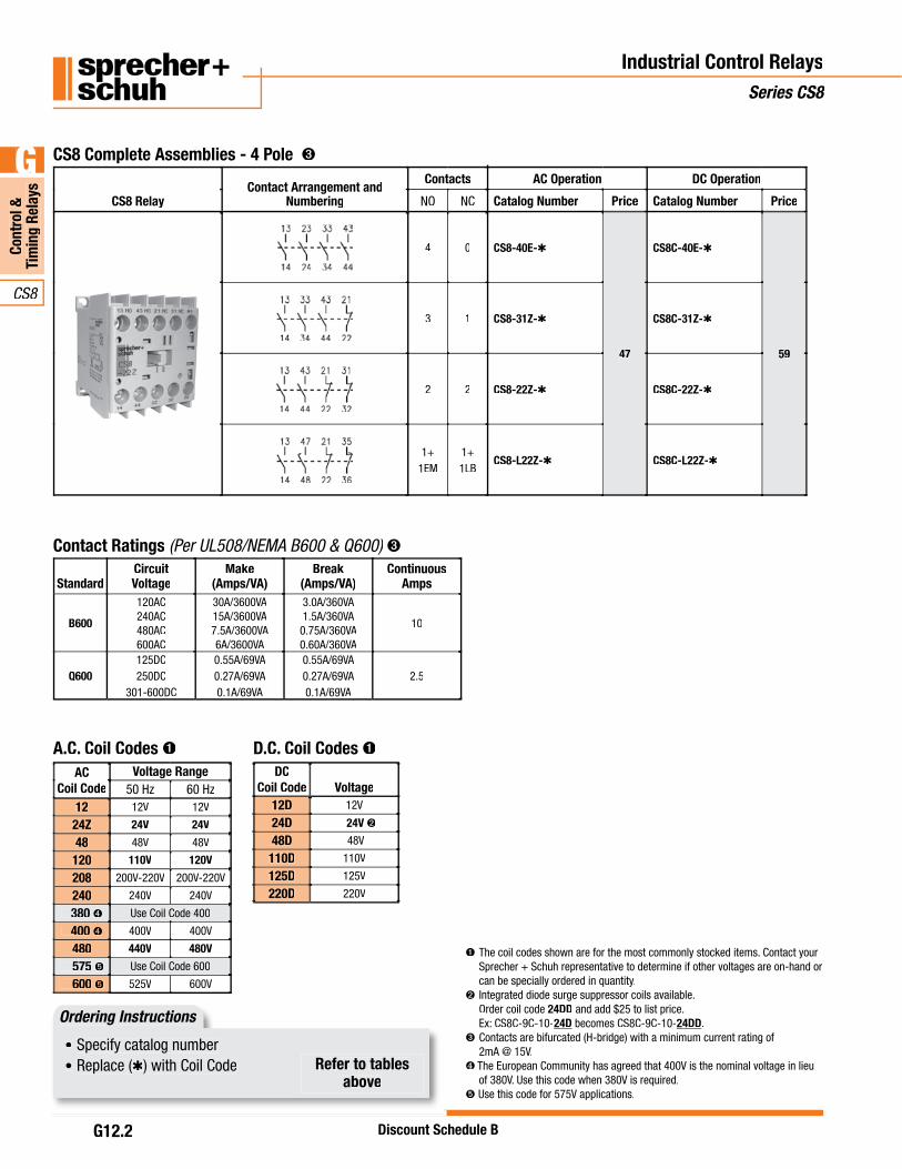
A.C. Coil Codes D.C. Coil CodesDC
Coil Code Voltage12D12D 12V
24D24D 24V
48D48D 48V
110D110D 110V
125D125D 125V
220D220D 220V
Industrial Control RelaysSeries CS8
CS8 RelayContact Arrangement and
Numbering
Contacts AC Operation DC Operation
NO NC Catalog Number Price Catalog Number Price
4 0 CS8-40E-
47
CS8C-40E-
59
3 1 CS8-31Z- CS8C-31Z-
2 2 CS8-22Z- CS8C-22Z-
1+1EM
1+1LB
CS8-L22Z- CS8C-L22Z-
CS8 Complete Assemblies - 4 Pole
The coil codes shown are for the most commonly stocked items. Contact yourSprecher + Schuh representative to determine if other voltages are on-hand orcan be specially ordered in quantity.
Integrated diode surge suppressor coils available.Order coil code 24DD and add $25 to list price.Ex: CS8C-9C-10-24D becomes CS8C-9C-10-24DD.Contacts are bifurcated (H-bridge) with a minimum current rating of2mA @ 15V.
The European Community has agreed that 400V is the nominal voltage in lieuof 380V. Use this code when 380V is required.Use this code for 575V applications.
Ordering Instructions
Specify catalog numberReplace ( ) with Coil Code Refer to tables
above
StandardCircuitVoltage
Make(Amps/VA)
Break(Amps/VA)
ContinuousAmps
B600
120AC240AC480AC600AC
30A/3600VA15A/3600VA7.5A/3600VA6A/3600VA
3.0A/360VA1.5A/360VA0.75A/360VA0.60A/360VA
10
Q600125DC250DC
301-600DC
0.55A/69VA0.27A/69VA0.1A/69VA
0.55A/69VA0.27A/69VA0.1A/69VA
2.5
Contact Ratings (Per UL508/NEMA B600 & Q600)
ACCoil Code
Voltage Range50 Hz 60 Hz
1212 12V 12V
24Z24Z 24V 24V
4848 48V 48V
120120 110V 120V
208208 200V-220V 200V-220V
240240 240V 240V
380 Use Coil Code 400
400 400 400V 400V
480480 440V 480V
575 Use Coil Code 600
600 600 525V 600V

GG
CS8
Control &Control &
Timing Relays
Timing Relays
Discount Schedule B G12.3
Industrial Control RelaysSeries CS8
Auxiliary contact ratings per UL 508/NEMA (B600/Q600). Contacts are bifurcated(H-bridge) with a minimum current rating of 15V@2mA.
AuxiliaryContact Blocks NO NC
ContactArrangement Catalog No. Price
2-Pole
Typical auxiliarycontact block
4-Pole
1 1 CS8-P11E
160 2 CS8-P02E
2 0 CS8-P20E
2 2 CS8-P22Z
32
3 1 CS8-P31Z
1 3 CS8-P13E
0 4 CS8-P04E
4 0 CS8-P40E
Auxiliary Contact Blocks (2 & 4 Pole)Auxiliary
Contact Blocks NO NCContact
Arrangement Catalog No. Price
2-Pole
Typical auxiliarycontact block
4-Pole
1 1 CA8-P11
160 2 CA8-P02
2 0 CA8-P20
2 2 CA8-P22
32
3 1 CA8-P31
1 3 CA8-P13
0 4 CA8-P04
4 0 CA8-P40
CS8
G
Cont
rol &
Tim
ing
Rela
ys
Discount Schedule BG12.4
Industrial Control RelaysSeries CS8
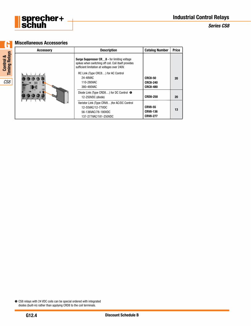
Accessory Description Catalog Number Price
Surge Suppressor CR__8 - for limiting voltage spikes when switching off coil. Coil itself provides sufficient limitation at voltages over 240V.
RC Link (Type CRC8…) for AC Control24-48VAC110-280VAC380-480VAC
Diode Link (Type CRD8…) for DC Control12-250VDC (diode)
Varistor Link (Type CRV8…)for AC/DC Control12-55VAC/12-77VDC56-136VAC/78-180VDC137-277VAC/181-250VDC
CRC8-50CRC8-240CRC8-480
CRD8-250
CRV8-55CRV8-136CRV8-277
20
20
13
Miscellaneous Accessories
CS8 relays with 24 VDC coils can be special ordered with integrated diodes (built-in) rather than applying CRD8 to the coil terminals.

G
CS8
Control &Tim
ing Relays
Discount Schedule B G12.5
Industrial Control RelaysSeries CS8
Technical InformationCS8 Auxiliary Contacts
ElectricalContact Ratings — NEMA B600, Q600 B600, Q600Contact Ratings — IEC AC-15 (solenoids, contactors)at rated voltageIEC 947, EN 60947NEMA A600
24…120V [A] 3 3230…240V [A] 2 2
400V [A] 1.2 1.2480…500V [A] 1 1600…690V [A} 0.6 0.6
AC-12 (Rated thermal current)
Ambient Temperature 40°C Ith 24…690V [A] 10 10Ambient Temperature 60°C Ith 24…240V [A] 6 6
Low Level Signal SwitchingContact design H-bridge bi-furcated H-bridge bi-furcatedMinimum switchingrecommendation
15V2mA
15V2mA
Short Circuit ProtectionCoordination Type 2acc. IEC 947-5-1
Fuse gG [A] 10 10
Switching DC-13 (Q600)1 pole 24V [A] 2.3 2.3
48V [A] 1 1110V [A] 0.55 0.55125V [A] 0.55 0.55220V [A] 0.27 0.27250V [A] 0.27 0.27400V [A] 0.15 0.15440V [A] 0.15 0.15600V [A] 0.1 0.1
Load Carrying Capacity according to UL/CSARated voltage AC [V] max. 600 max. 600
DC [V] max. 600 max. 600Continuous rating (40ºC) AC [A] 10 10Switching Capacity AC [A] B600 B600
DC [A] Q600 Q600Continuous rating (general purpose) 300V [V] 5 5
600V [V] 10 10
Resistance and Power DissipationMain current circuit resistance, 1 pole [m ] 6.5 6.5
Power dissipation Ith, 4 poles [W] 2.6 2.6
Total Power dissipation
Ith AC control, warm [W] 4.4 4.4
DC control, warm [W] 5.2 5.2

CS8
G
Cont
rol &
Tim
ing
Rela
ys
Discount Schedule BG12.6
CS8 Relays
MechanicalMechanical Life [Mil. Op] 15Electrical LifeAC-15 (240V, 2A) AC Operations [Mil. Op] 0.7Weight AC control [kg/lbs] 0.16 (0.35)
DC control [kg/lbs] 0.2 (0.44)
Terminations -Main contacts and Auxiliary contacts
Terminal Type Combination Screw Head: Cross, Slotted, Pozidrive
Finestrandedw/ ferrule
1 wire2 wires
[mm2][mm2]
0.75...2.50.75...2.5
Solid orcoarsestranded
1 wire2 wires
[mm2][mm2]
1…40.75...2.5 + 1…4
Max. Wire Size [AWG] 18…12
Tightening Torque [Nm] 1.2
[lb-in] 10.6
Control CircuitOperating VoltageAC 50/60 Hz Pickup [x Us] 0.85…1.1
Dropout [x Us] 0.2...0.75DC Pickup [x Us] 0.8…1.1
[x Us] 9,12,24,110V DC: 0.7...1.25
with protection circuit Dropout [x Us] 0.1...0.75Coil ConsumptionAC 50/60 Hz Inrush [VA/W] 35/32
Seal [VA/W] 5/1.8DC Inrush/Seal [W] cold 3.0, warm 2.6Operating TimesAC- 50/60 Hz Pickup Time [ms] 15…40
Dropout Time [ms] 15…33With RC module Pickup Time [ms] 15…28DC Pickup Time [ms] 18…40
Dropout Time [ms] 6…12With Integ. diode Pickup Time [ms] 8…12With External diode Pickup Time [ms] 35…50
Industrial Control RelaysSeries CS8
CS8 Relays
GeneralRated Voltage Withstand UIEC 690VUL; CSA 600VRated Impulse Strength Uimp 6 kVRated Voltage Ue
AC [V] 24, 48, 120, 230, 400, 500, 600, 690DC [V] 24, 48, 110, 220, 440VRated Frequency AC 50/60 Hz, DCAmbient TemperatureStorage –55...+80°C (–67...176°F)Operation at nominal current –25...+60°C (–13...140°F)At 85% rated operation current –25...+70ºC (–13... 158ºF)Resistance to Climatic Change 40º C (104º F), 95% relative humidity,
56 days
23º C (73.4 º F), 83%/40 ºC (104 ºF), 93%, 56 cycles
Altitude 2000m M.S.L., per IEC 60947-4-1Type of Protection IP2X
StandardsIEC/EN 60947-1, -5-1, -5-4;
UL 508; CSA 22.2. No. 14
Approvals
Technical Information
Pozidrive No.2 / Blade No.3 screw

G
CS8
Control &Tim
ing Relays
Discount Schedule B G12.7
Industrial Control RelaysSeries CS8
Series CS8 Industrial Control Relays

CS8
G
Cont
rol &
Tim
ing
Rela
ys
Discount Schedule BG12.8
Notes
Industrial Control RelaysSeries CS8

PUB NO: LIT-CAT-CA8-107
Sprecher + Schuh USA Headquarters15910 International Plaza DriveHouston, Texas 77032Tel: 281.442.9000 Fax: 800.739.7370
Sprecher + Schuh Canada Division3610 Nashua Drive, Unit 10MIssissauga, ON L4V 1L2Tel: 905.677.7514 Fax: 805.677.7663
www.sprecherschuh.com