Embed Size (px)
Citation preview

MIMO-OFDM for LTE, WIFI and WIMAXCoherent versus Non-Coherent and Cooperative Turbo-Transceivers
by
L. Hanzo, J. Akhtman, M. Jiang, L. Wang
UNIVERSITY OF SOUTHAMPTON
We dedicate this monograph to the numerous contributors of this field, many of whom are listed in the Author Index
The MIMO capacity theoretically increases linearly with the number of transmit antennas, provided that the number ofreceive antennas is equal to the number of transmit antennas. With the further proviso that the total transmit power isincreased proportionately to the number of transmit antennas, a linear capacity increase is achieved upon increasingthe transmit power. However, under realistic conditions the theoretical MIMO-OFDM performance erodes and henceto circumvent this degradation, our monograph is dedicatedto the design of practical coherent, non-coherent andcooperative MIMO-OFDM turbo-transceivers...

ii

Contents
About the Authors xv
Other Wiley and IEEE Press Books on Related Topics xviii
Acknowledgments xxi
Preface xxiii
List of Symbols xxv
1 Introduction to OFDM and MIMO-OFDM 1
1.1 OFDM History . . . . . . . . . . . . . . . . . . . . . . . . . . . . . . . . . . . . .. . . . . . . . . 1
1.1.1 Multiple-Input Multiple-Output Assisted OFDM . . . . .. . . . . . . . . . . . . . . . . . . 2
1.1.1.1 The Benefits of MIMOs . . . . . . . . . . . . . . . . . . . . . . . . . . .. . . . . 2
1.1.1.2 MIMO OFDM . . . . . . . . . . . . . . . . . . . . . . . . . . . . . . . . . . . .. 5
1.1.1.3 SDMA-based MIMO OFDM Systems . . . . . . . . . . . . . . . . . . .. . . . . 5
1.2 OFDM Schematic . . . . . . . . . . . . . . . . . . . . . . . . . . . . . . . . . . .. . . . . . . . . . 7
1.3 Channel Estimation for Multicarrier Systems . . . . . . . . .. . . . . . . . . . . . . . . . . . . . . 12
1.4 Channel Estimation for MIMO-OFDM . . . . . . . . . . . . . . . . . . .. . . . . . . . . . . . . . . 14
1.5 Signal Detection in MIMO-OFDM Systems . . . . . . . . . . . . . . .. . . . . . . . . . . . . . . . 15
1.6 Iterative Signal Processing for SDM-OFDM . . . . . . . . . . . .. . . . . . . . . . . . . . . . . . . 19
1.7 System Model . . . . . . . . . . . . . . . . . . . . . . . . . . . . . . . . . . . . .. . . . . . . . . . 20
1.7.1 Channel Statistics . . . . . . . . . . . . . . . . . . . . . . . . . . . . .. . . . . . . . . . . . 20
1.7.2 Realistic Channel Properties . . . . . . . . . . . . . . . . . . . .. . . . . . . . . . . . . . . 23
1.7.3 Baseline Scenario Characteristics . . . . . . . . . . . . . . .. . . . . . . . . . . . . . . . . 24
1.7.4 MC Transceiver . . . . . . . . . . . . . . . . . . . . . . . . . . . . . . . . .. . . . . . . . . 25
1.8 SDM-OFDM System Model . . . . . . . . . . . . . . . . . . . . . . . . . . . . .. . . . . . . . . . 26
1.8.1 MIMO Channel Model . . . . . . . . . . . . . . . . . . . . . . . . . . . . . .. . . . . . . . 26
1.8.2 Channel Capacity . . . . . . . . . . . . . . . . . . . . . . . . . . . . . . .. . . . . . . . . . 27
1.8.3 SDM-OFDM Transceiver Structure . . . . . . . . . . . . . . . . . .. . . . . . . . . . . . . 28
1.9 Novel Aspects and Outline of the Book . . . . . . . . . . . . . . . . .. . . . . . . . . . . . . . . . 30
iii

iv CONTENTS
1.10 Chapter Summary . . . . . . . . . . . . . . . . . . . . . . . . . . . . . . . . .. . . . . . . . . . . . 32
2 OFDM Standards 33
2.1 Wi-Fi . . . . . . . . . . . . . . . . . . . . . . . . . . . . . . . . . . . . . . . . . . .. . . . . . . . 33
2.1.1 IEEE 802.11 Standards . . . . . . . . . . . . . . . . . . . . . . . . . . .. . . . . . . . . . . 33
2.2 3GPP Long-Term Evolution . . . . . . . . . . . . . . . . . . . . . . . . . .. . . . . . . . . . . . . 35
2.3 WiMAX Evolution . . . . . . . . . . . . . . . . . . . . . . . . . . . . . . . . . .. . . . . . . . . . 36
2.3.1 Historic Background . . . . . . . . . . . . . . . . . . . . . . . . . . . .. . . . . . . . . . . 38
2.3.1.1 IEEE 802.16 Standard Family . . . . . . . . . . . . . . . . . . . .. . . . . . . . . 38
2.3.1.2 Early 802.16 Standards . . . . . . . . . . . . . . . . . . . . . . . .. . . . . . . . 38
2.3.1.2.1 802.16d-2004 - Fixed WiMAX . . . . . . . . . . . . . . . . . . .. . . 40
2.3.1.2.2 802.16e-2005 - Mobile WiMAX . . . . . . . . . . . . . . . . . .. . . 40
2.3.1.2.3 Other 802.16 Standards . . . . . . . . . . . . . . . . . . . . . .. . . . 41
2.3.1.3 WiMAX Forum . . . . . . . . . . . . . . . . . . . . . . . . . . . . . . . . . .. . 42
2.3.1.4 WiMAX and WiBro . . . . . . . . . . . . . . . . . . . . . . . . . . . . . . .. . . 42
2.3.2 Technical Aspects of WiMAX . . . . . . . . . . . . . . . . . . . . . . .. . . . . . . . . . . 43
2.3.2.1 WiMAX-I: 802.16-2004 and 802.16e-2005 . . . . . . . . . .. . . . . . . . . . . . 44
2.3.2.1.1 OFDMA System Configuration . . . . . . . . . . . . . . . . . . .. . . 44
2.3.2.1.2 Frame Structure . . . . . . . . . . . . . . . . . . . . . . . . . . . .. . 45
2.3.2.1.3 Subcarrier Mapping . . . . . . . . . . . . . . . . . . . . . . . . .. . . 45
2.3.2.1.4 Channel Coding . . . . . . . . . . . . . . . . . . . . . . . . . . . . .. 46
2.3.2.1.5 MIMO Support . . . . . . . . . . . . . . . . . . . . . . . . . . . . . . 46
2.3.2.1.6 Other Aspects . . . . . . . . . . . . . . . . . . . . . . . . . . . . . .. 46
2.3.2.2 WiMAX-II: 802.16m . . . . . . . . . . . . . . . . . . . . . . . . . . . .. . . . . 48
2.3.2.2.1 System Requirements . . . . . . . . . . . . . . . . . . . . . . . .. . . 48
2.3.2.2.2 System Description . . . . . . . . . . . . . . . . . . . . . . . . .. . . 50
2.3.3 The Future of WiMAX . . . . . . . . . . . . . . . . . . . . . . . . . . . . . .. . . . . . . . 54
2.4 Chapter Summary . . . . . . . . . . . . . . . . . . . . . . . . . . . . . . . . . .. . . . . . . . . . . 55
I Coherently Detected SDMA-OFDM Systems 57
3 Channel Coding Assisted STBC-OFDM Systems 59
3.1 Introduction . . . . . . . . . . . . . . . . . . . . . . . . . . . . . . . . . . . .. . . . . . . . . . . . 59
3.2 Space-Time Block Codes . . . . . . . . . . . . . . . . . . . . . . . . . . . .. . . . . . . . . . . . . 59
3.2.1 Alamouti’sG2 Space-Time Block Code . . . . . . . . . . . . . . . . . . . . . . . . . . . . . 59
3.2.2 Encoding Algorithm . . . . . . . . . . . . . . . . . . . . . . . . . . . . .. . . . . . . . . . 61
3.2.2.1 Transmission Matrix . . . . . . . . . . . . . . . . . . . . . . . . . .. . . . . . . . 61
3.2.2.2 Encoding Algorithm of the Space-Time Block CodeG2 . . . . . . . . . . . . . . . 62
3.2.2.3 Other Space-Time Block Codes . . . . . . . . . . . . . . . . . . .. . . . . . . . . 62
3.2.3 Decoding Algorithm . . . . . . . . . . . . . . . . . . . . . . . . . . . . .. . . . . . . . . . 63
3.2.3.1 Maximum Likelihood Decoding . . . . . . . . . . . . . . . . . . .. . . . . . . . 63

CONTENTS v
3.2.3.2 Maximum-A-Posteriori Decoding . . . . . . . . . . . . . . . .. . . . . . . . . . . 64
3.2.4 System Overview . . . . . . . . . . . . . . . . . . . . . . . . . . . . . . . .. . . . . . . . . 65
3.2.5 Simulation Results . . . . . . . . . . . . . . . . . . . . . . . . . . . . .. . . . . . . . . . . 66
3.2.5.1 Performance over Uncorrelated Rayleigh Fading Channels . . . . . . . . . . . . . 66
3.2.5.2 Performance over Correlated Rayleigh Fading Channel . . . . . . . . . . . . . . . 70
3.2.6 Conclusions . . . . . . . . . . . . . . . . . . . . . . . . . . . . . . . . . . .. . . . . . . . . 70
3.3 Channel Coded Space-Time Block Codes . . . . . . . . . . . . . . . .. . . . . . . . . . . . . . . . 71
3.3.1 Space-Time Block Codes with LDPC Channel Codes . . . . . .. . . . . . . . . . . . . . . . 72
3.3.1.1 System Overview . . . . . . . . . . . . . . . . . . . . . . . . . . . . . .. . . . . 72
3.3.1.2 Simulation Results . . . . . . . . . . . . . . . . . . . . . . . . . . .. . . . . . . . 73
3.3.1.2.1 Performance over Uncorrelated Rayleigh Fading Channels . . . . . . . 73
3.3.1.2.2 Performance over Correlated Rayleigh Fading Channels . . . . . . . . . 78
3.3.1.3 Complexity Issues . . . . . . . . . . . . . . . . . . . . . . . . . . . .. . . . . . . 79
3.3.1.4 Conclusions . . . . . . . . . . . . . . . . . . . . . . . . . . . . . . . . .. . . . . 83
3.3.2 LDPC-Aided and TC-Aided Space-Time Block Codes . . . . .. . . . . . . . . . . . . . . . 84
3.3.2.1 System Overview . . . . . . . . . . . . . . . . . . . . . . . . . . . . . .. . . . . 85
3.3.2.2 Complexity Issues . . . . . . . . . . . . . . . . . . . . . . . . . . . .. . . . . . . 86
3.3.2.3 Simulation Results . . . . . . . . . . . . . . . . . . . . . . . . . . .. . . . . . . . 87
3.3.2.4 Conclusions . . . . . . . . . . . . . . . . . . . . . . . . . . . . . . . . .. . . . . 88
3.4 Channel Coding Aided Space-Time Block Coded OFDM . . . . . .. . . . . . . . . . . . . . . . . . 90
3.4.1 Coded Modulation Assisted Space-Time Block Codes . . .. . . . . . . . . . . . . . . . . . 90
3.4.1.1 Coded Modulation Principles . . . . . . . . . . . . . . . . . . .. . . . . . . . . . 90
3.4.1.2 Inter-Symbol Interference and OFDM Basics . . . . . . .. . . . . . . . . . . . . . 90
3.4.1.3 System Overview . . . . . . . . . . . . . . . . . . . . . . . . . . . . . .. . . . . 91
3.4.1.3.1 Complexity Issues . . . . . . . . . . . . . . . . . . . . . . . . . .. . . 92
3.4.1.3.2 Channel Model . . . . . . . . . . . . . . . . . . . . . . . . . . . . . .92
3.4.1.3.3 Assumptions . . . . . . . . . . . . . . . . . . . . . . . . . . . . . . .. 94
3.4.1.4 Simulation Results . . . . . . . . . . . . . . . . . . . . . . . . . . .. . . . . . . . 94
3.4.1.5 Conclusions . . . . . . . . . . . . . . . . . . . . . . . . . . . . . . . . .. . . . . 96
3.4.2 CM-Aided and LDPC-Aided Space-Time Block Coded OFDM Schemes . . . . . . . . . . . 97
3.4.2.1 System Overview . . . . . . . . . . . . . . . . . . . . . . . . . . . . . .. . . . . 97
3.4.2.2 Simulation Results . . . . . . . . . . . . . . . . . . . . . . . . . . .. . . . . . . . 98
3.4.2.3 Conclusions . . . . . . . . . . . . . . . . . . . . . . . . . . . . . . . . .. . . . . 99
3.5 Chapter Summary . . . . . . . . . . . . . . . . . . . . . . . . . . . . . . . . . .. . . . . . . . . . . 99
4 Coded Modulation Assisted Multi-User SDMA-OFDM Using Frequency-Domain Spreading 103
4.1 Introduction . . . . . . . . . . . . . . . . . . . . . . . . . . . . . . . . . . . .. . . . . . . . . . . . 103
4.2 System Model . . . . . . . . . . . . . . . . . . . . . . . . . . . . . . . . . . . . .. . . . . . . . . . 104
4.2.1 SDMA MIMO Channel Model . . . . . . . . . . . . . . . . . . . . . . . . . .. . . . . . . . 104
4.2.2 CM-assisted SDMA-OFDM Using Frequency Domain Spreading . . . . . . . . . . . . . . . 105
4.2.2.1 Minimum Mean-Square Error Multi-User Detector . . .. . . . . . . . . . . . . . . 105

vi CONTENTS
4.2.2.2 Subcarrier-based Walsh-Hadamard Transform Spreading . . . . . . . . . . . . . . 106
4.3 Simulation Results . . . . . . . . . . . . . . . . . . . . . . . . . . . . . . .. . . . . . . . . . . . . 107
4.3.1 MMSE-SDMA-OFDM Using WHTS . . . . . . . . . . . . . . . . . . . . . . .. . . . . . . 107
4.3.2 CM- and WHTS-assisted MMSE-SDMA-OFDM . . . . . . . . . . . . .. . . . . . . . . . . 108
4.3.2.1 Performance Over the SWATM Channel . . . . . . . . . . . . . .. . . . . . . . . 108
4.3.2.1.1 Two Receiver Antenna Elements . . . . . . . . . . . . . . . .. . . . . 108
4.3.2.1.2 Four Receiver Antenna Elements . . . . . . . . . . . . . . .. . . . . . 110
4.3.2.2 Performance Over the COST207 HT Channel . . . . . . . . . .. . . . . . . . . . 112
4.3.2.2.1 Two Receiver Antenna Elements . . . . . . . . . . . . . . . .. . . . . 112
4.3.2.2.2 Four Receiver Antenna Elements . . . . . . . . . . . . . . .. . . . . . 120
4.3.2.2.3 Performance Comparisons . . . . . . . . . . . . . . . . . . . .. . . . 123
4.3.2.3 Effects of the WHT Block Size . . . . . . . . . . . . . . . . . . . .. . . . . . . . 124
4.3.2.4 Effects of the Doppler Frequency . . . . . . . . . . . . . . . .. . . . . . . . . . . 127
4.4 Chapter Summary . . . . . . . . . . . . . . . . . . . . . . . . . . . . . . . . . .. . . . . . . . . . . 128
5 Hybrid Multi-User Detection for SDMA-OFDM Systems 131
5.1 Introduction . . . . . . . . . . . . . . . . . . . . . . . . . . . . . . . . . . . .. . . . . . . . . . . . 131
5.2 Genetical Algorithm Assisted Multi-User Detection . . .. . . . . . . . . . . . . . . . . . . . . . . . 132
5.2.1 System Overview . . . . . . . . . . . . . . . . . . . . . . . . . . . . . . . .. . . . . . . . . 132
5.2.2 MMSE-GA-concatenated Multi-User Detector . . . . . . . .. . . . . . . . . . . . . . . . . 133
5.2.2.1 Optimization Metric for the GA MUD . . . . . . . . . . . . . . .. . . . . . . . . 133
5.2.2.2 Concatenated MMSE-GA Multi-User Detection . . . . . .. . . . . . . . . . . . . 134
5.2.3 Simulation Results . . . . . . . . . . . . . . . . . . . . . . . . . . . . .. . . . . . . . . . . 135
5.2.4 Complexity Analysis . . . . . . . . . . . . . . . . . . . . . . . . . . . .. . . . . . . . . . . 137
5.2.5 Conclusions . . . . . . . . . . . . . . . . . . . . . . . . . . . . . . . . . . .. . . . . . . . . 138
5.3 Enhanced GA-based Multi-User Detection . . . . . . . . . . . . .. . . . . . . . . . . . . . . . . . . 138
5.3.1 Improved Mutation Scheme . . . . . . . . . . . . . . . . . . . . . . . .. . . . . . . . . . . 139
5.3.1.1 Conventional Uniform Mutation . . . . . . . . . . . . . . . . .. . . . . . . . . . 139
5.3.1.2 BiasedQ-function Based Mutation . . . . . . . . . . . . . . . . . . . . . . . . . . 140
5.3.1.2.1 Theoretical Foundations . . . . . . . . . . . . . . . . . . . .. . . . . . 140
5.3.1.2.2 Simplified BQM . . . . . . . . . . . . . . . . . . . . . . . . . . . . . .142
5.3.1.3 Simulation Results . . . . . . . . . . . . . . . . . . . . . . . . . . .. . . . . . . . 143
5.3.1.3.1 BQM Versus UM . . . . . . . . . . . . . . . . . . . . . . . . . . . . . 144
5.3.1.3.2 BQM Versus CNUM . . . . . . . . . . . . . . . . . . . . . . . . . . . 145
5.3.2 Iterative MUD Framework . . . . . . . . . . . . . . . . . . . . . . . . .. . . . . . . . . . . 145
5.3.2.1 MMSE-initialized Iterative GA MUD . . . . . . . . . . . . . .. . . . . . . . . . . 147
5.3.2.2 Simulation Results . . . . . . . . . . . . . . . . . . . . . . . . . . .. . . . . . . . 148
5.3.2.2.1 Performance in Underloaded and Fully-loaded Scenarios . . . . . . . . 148
5.3.2.2.1.1 BQM-IGA Performance . . . . . . . . . . . . . . . . . . . . . .. . . . 149
5.3.2.2.1.2 Effects of the Number of IGA MUD Iterations . . . .. . . . . . . . . . 150
5.3.2.2.1.3 Effects of the User Load . . . . . . . . . . . . . . . . . . . .. . . . . . 150

CONTENTS vii
5.3.2.2.2 Performance in Overloaded Scenarios . . . . . . . . . .. . . . . . . . 152
5.3.2.2.2.1 Overloaded BQM-IGA . . . . . . . . . . . . . . . . . . . . . . .. . . . 152
5.3.2.2.2.2 BQM Versus CNUM . . . . . . . . . . . . . . . . . . . . . . . . . . .. 153
5.3.2.2.3 Performance Under Imperfect Channel Estimation. . . . . . . . . . . . 153
5.3.3 Complexity Analysis . . . . . . . . . . . . . . . . . . . . . . . . . . . .. . . . . . . . . . . 154
5.3.4 Conclusions . . . . . . . . . . . . . . . . . . . . . . . . . . . . . . . . . . .. . . . . . . . . 156
5.4 Chapter Summary . . . . . . . . . . . . . . . . . . . . . . . . . . . . . . . . . .. . . . . . . . . . . 158
6 DS-Spreading and Slow Subcarrier-Hopping Aided Multi-User SDMA-OFDM Systems 161
6.1 Conventional SDMA-OFDM Systems . . . . . . . . . . . . . . . . . . . .. . . . . . . . . . . . . . 161
6.2 Introduction to Hybrid SDMA-OFDM . . . . . . . . . . . . . . . . . . .. . . . . . . . . . . . . . . 161
6.3 Subband-Hopping Versus Subcarrier-Hopping . . . . . . . . .. . . . . . . . . . . . . . . . . . . . . 163
6.4 System Architecture . . . . . . . . . . . . . . . . . . . . . . . . . . . . . .. . . . . . . . . . . . . . 164
6.4.1 System Overview . . . . . . . . . . . . . . . . . . . . . . . . . . . . . . . .. . . . . . . . . 164
6.4.1.1 Transmitter Structure . . . . . . . . . . . . . . . . . . . . . . . .. . . . . . . . . 165
6.4.1.2 Receiver Structure . . . . . . . . . . . . . . . . . . . . . . . . . . .. . . . . . . . 167
6.4.2 Subcarrier-Hopping Strategy Design . . . . . . . . . . . . . .. . . . . . . . . . . . . . . . . 167
6.4.2.1 Random SSCH . . . . . . . . . . . . . . . . . . . . . . . . . . . . . . . . . .. . . 169
6.4.2.2 Uniform SSCH . . . . . . . . . . . . . . . . . . . . . . . . . . . . . . . . .. . . 169
6.4.2.2.1 Design of the USSCH Pattern . . . . . . . . . . . . . . . . . . .. . . . 169
6.4.2.2.2 Discussions . . . . . . . . . . . . . . . . . . . . . . . . . . . . . . .. 172
6.4.2.3 Random and Uniform SFH . . . . . . . . . . . . . . . . . . . . . . . . .. . . . . 172
6.4.2.4 Offline Pattern Pre-computation . . . . . . . . . . . . . . . .. . . . . . . . . . . . 172
6.4.3 DSS Despreading and SSCH Demapping . . . . . . . . . . . . . . . .. . . . . . . . . . . . 173
6.4.4 Multi-User Detection . . . . . . . . . . . . . . . . . . . . . . . . . . .. . . . . . . . . . . . 175
6.5 Simulation Results . . . . . . . . . . . . . . . . . . . . . . . . . . . . . . .. . . . . . . . . . . . . 176
6.5.1 MMSE Aided Versus MMSE-IGA Aided DSS/SSCH SDMA-OFDM .. . . . . . . . . . . . 178
6.5.2 SDMA-OFDM Using SFH and Hybrid DSS/SSCH Techniques . .. . . . . . . . . . . . . . 178
6.5.2.1 Moderately Overloaded Scenarios . . . . . . . . . . . . . . .. . . . . . . . . . . . 179
6.5.2.2 Highly Overloaded Scenarios . . . . . . . . . . . . . . . . . . .. . . . . . . . . . 180
6.5.3 Performance Enhancements by Increasing Receiver Diversity . . . . . . . . . . . . . . . . . 182
6.5.4 Performance Under Imperfect Channel Estimation . . . .. . . . . . . . . . . . . . . . . . . 182
6.6 Complexity Issues . . . . . . . . . . . . . . . . . . . . . . . . . . . . . . . .. . . . . . . . . . . . . 184
6.7 Conclusions . . . . . . . . . . . . . . . . . . . . . . . . . . . . . . . . . . . . .. . . . . . . . . . . 184
6.8 Chapter Summary . . . . . . . . . . . . . . . . . . . . . . . . . . . . . . . . . .. . . . . . . . . . . 184
7 Channel Estimation for OFDM and MC-CDMA 187
7.1 Pilot-Assisted Channel Estimation . . . . . . . . . . . . . . . . .. . . . . . . . . . . . . . . . . . . 187
7.2 Decision Directed Channel Estimation . . . . . . . . . . . . . . .. . . . . . . . . . . . . . . . . . . 188
7.3 A PosterioriFD-CTF Estimation . . . . . . . . . . . . . . . . . . . . . . . . . . . . . . . . . . .. . 189
7.3.1 Least Squares CTF Estimator . . . . . . . . . . . . . . . . . . . . . .. . . . . . . . . . . . 189
viii CONTENTS
7.3.2 MMSE CTF Estimator . . . . . . . . . . . . . . . . . . . . . . . . . . . . . .. . . . . . . . 190
7.3.3 A Priori Predicted Value Aided CTF Estimator . . . . . . . . . . . . . . . . . . . .. . . . . 191
7.4 A PosterioriCIR Estimation . . . . . . . . . . . . . . . . . . . . . . . . . . . . . . . . . . . . . .. 191
7.4.1 MMSE SS-CIR Estimator . . . . . . . . . . . . . . . . . . . . . . . . . . .. . . . . . . . . 191
7.4.2 Reduced Complexity SS-CIR Estimator . . . . . . . . . . . . . .. . . . . . . . . . . . . . . 193
7.4.3 Complexity Study . . . . . . . . . . . . . . . . . . . . . . . . . . . . . . .. . . . . . . . . 195
7.4.4 MMSE FS-CIR Estimator . . . . . . . . . . . . . . . . . . . . . . . . . . .. . . . . . . . . 195
7.4.5 Performance Ananlysis . . . . . . . . . . . . . . . . . . . . . . . . . .. . . . . . . . . . . . 196
7.4.5.1 Reduced Complexity MMSE SS-CIR Estimator Performance . . . . . . . . . . . . 198
7.4.5.2 Fractionally-Spaced CIR Estimator Performance . .. . . . . . . . . . . . . . . . . 198
7.5 Parametric FS-CIR Estimation . . . . . . . . . . . . . . . . . . . . . .. . . . . . . . . . . . . . . . 200
7.5.1 Projection Approximation Subspace Tracking . . . . . . .. . . . . . . . . . . . . . . . . . . 200
7.5.2 Deflation PAST . . . . . . . . . . . . . . . . . . . . . . . . . . . . . . . . . .. . . . . . . . 203
7.5.3 PASTD -Aided FS-CIR Estimation . . . . . . . . . . . . . . . . . . . . . . . . . . . . .. . . 204
7.6 Time-DomainA Priori CIR Tap Prediction . . . . . . . . . . . . . . . . . . . . . . . . . . . . . . . . 206
7.6.1 MMSE Predictor . . . . . . . . . . . . . . . . . . . . . . . . . . . . . . . . .. . . . . . . . 206
7.6.2 Robust Predictor . . . . . . . . . . . . . . . . . . . . . . . . . . . . . . .. . . . . . . . . . 209
7.6.3 MMSE Versus Robust Predictor Performance Comparison. . . . . . . . . . . . . . . . . . . 210
7.6.4 Adaptive RLS Predictor . . . . . . . . . . . . . . . . . . . . . . . . . .. . . . . . . . . . . 210
7.6.5 Robust Versus Adaptive Predictor Performance Comparison . . . . . . . . . . . . . . . . . . 212
7.7 PASTD Aided DDCE . . . . . . . . . . . . . . . . . . . . . . . . . . . . . . . . . . . . . . . . . .. 213
7.8 Channel Estimation for MIMO-OFDM . . . . . . . . . . . . . . . . . . .. . . . . . . . . . . . . . . 216
7.8.1 Soft Recursive MIMO-CTF Estimation . . . . . . . . . . . . . . .. . . . . . . . . . . . . . 216
7.8.1.1 LMS MIMO-CTF Estimator . . . . . . . . . . . . . . . . . . . . . . . .. . . . . 216
7.8.1.2 RLS MIMO-CTF Estimator . . . . . . . . . . . . . . . . . . . . . . . .. . . . . . 217
7.8.1.3 Soft-Feedback Aided RLS MIMO-CTF Estimator . . . . . .. . . . . . . . . . . . 217
7.8.1.4 Modified-RLS MIMO-CTF Estimator . . . . . . . . . . . . . . . .. . . . . . . . 218
7.8.1.5 MIMO-CTF Estimator Performance Analysis . . . . . . . .. . . . . . . . . . . . 219
7.8.2 PASTD -Aided DDCE for MIMO-OFDM . . . . . . . . . . . . . . . . . . . . . . . . . . . . 221
7.8.2.1 PASTD -Aided MIMO-DDCE Performance Analysis . . . . . . . . . . . . . . . . 223
8 Iterative Joint Channel Estimation and MUD for SDMA-OFDM S ystems 227
8.1 Introduction . . . . . . . . . . . . . . . . . . . . . . . . . . . . . . . . . . . .. . . . . . . . . . . . 227
8.2 System Overview . . . . . . . . . . . . . . . . . . . . . . . . . . . . . . . . . .. . . . . . . . . . . 228
8.3 GA-assisted Iterative Joint Channel Estimation and MUD. . . . . . . . . . . . . . . . . . . . . . . . 228
8.3.1 Pilot-aided Initial Channel Estimation . . . . . . . . . . .. . . . . . . . . . . . . . . . . . . 231
8.3.2 Generating Initial Symbol Estimates . . . . . . . . . . . . . .. . . . . . . . . . . . . . . . . 232
8.3.3 GA-aided Joint Optimization Providing Soft Outputs .. . . . . . . . . . . . . . . . . . . . . 234
8.3.3.1 Extended GA Individual Structure . . . . . . . . . . . . . . .. . . . . . . . . . . 234
8.3.3.2 Initialization . . . . . . . . . . . . . . . . . . . . . . . . . . . . . .. . . . . . . . 234
8.3.3.3 Joint Genetic Optimization . . . . . . . . . . . . . . . . . . . .. . . . . . . . . . 235

CONTENTS ix
8.3.3.3.1 Cross-over Operator . . . . . . . . . . . . . . . . . . . . . . . .. . . . 235
8.3.3.3.2 Mutation Operator . . . . . . . . . . . . . . . . . . . . . . . . . .. . . 236
8.3.3.3.3 Comments on the Joint Optimization Process . . . . .. . . . . . . . . 236
8.3.3.4 Generating the GA’s Soft Outputs . . . . . . . . . . . . . . . .. . . . . . . . . . . 236
8.4 Simulation Results . . . . . . . . . . . . . . . . . . . . . . . . . . . . . . .. . . . . . . . . . . . . 238
8.4.1 Effects of the Maximum Mutation Step Size . . . . . . . . . . .. . . . . . . . . . . . . . . . 238
8.4.2 Effects of the Doppler Frequency . . . . . . . . . . . . . . . . . .. . . . . . . . . . . . . . 241
8.4.3 Effects of the Number of GA-JCEMUD Iterations . . . . . . .. . . . . . . . . . . . . . . . 242
8.4.4 Effects of the Pilot Overhead . . . . . . . . . . . . . . . . . . . . .. . . . . . . . . . . . . . 242
8.4.5 Joint Optimization Versus Separate Optimization . . .. . . . . . . . . . . . . . . . . . . . . 242
8.4.6 Comparison of GA-JCEMUDs Having Soft and Hard Outputs. . . . . . . . . . . . . . . . . 244
8.4.7 MIMO Robustness . . . . . . . . . . . . . . . . . . . . . . . . . . . . . . . .. . . . . . . . 244
8.5 Conclusions . . . . . . . . . . . . . . . . . . . . . . . . . . . . . . . . . . . . .. . . . . . . . . . . 245
8.6 Chapter Summary . . . . . . . . . . . . . . . . . . . . . . . . . . . . . . . . . .. . . . . . . . . . . 245
II Coherent versus Non-Coherent and Cooperative OFDM Systems 249
List of Symbols in Part II 251
9 Reduced-Complexity Sphere Detection for Uncoded SDMA-OFDM Systems 253
9.1 Introduction . . . . . . . . . . . . . . . . . . . . . . . . . . . . . . . . . . . .. . . . . . . . . . . . 253
9.1.1 System Model . . . . . . . . . . . . . . . . . . . . . . . . . . . . . . . . . . .. . . . . . . 253
9.1.2 Maximum Likelihood Detection . . . . . . . . . . . . . . . . . . . .. . . . . . . . . . . . . 254
9.1.3 Chapter Contributions and Outline . . . . . . . . . . . . . . . .. . . . . . . . . . . . . . . . 255
9.2 Principle of Sphere Detection . . . . . . . . . . . . . . . . . . . . . .. . . . . . . . . . . . . . . . . 256
9.2.1 Transformation of the Maximum-Likelihood Metric . . .. . . . . . . . . . . . . . . . . . . 256
9.2.2 Depth-First Tree Search . . . . . . . . . . . . . . . . . . . . . . . . .. . . . . . . . . . . . 256
9.2.3 Breadth-First Tree Search . . . . . . . . . . . . . . . . . . . . . . .. . . . . . . . . . . . . 259
9.2.4 Generalized Sphere Detection for Rank-Deficient Systems . . . . . . . . . . . . . . . . . . . 260
9.2.4.1 Generalized Sphere Detection . . . . . . . . . . . . . . . . . .. . . . . . . . . . . 260
9.2.4.2 Generalized Sphere Detection Using a Modified Grammian Matrix . . . . . . . . . 261
9.2.5 Simulation Results . . . . . . . . . . . . . . . . . . . . . . . . . . . . .. . . . . . . . . . . 261
9.3 Complexity-Reduction Schemes for SD . . . . . . . . . . . . . . . .. . . . . . . . . . . . . . . . . 264
9.3.1 Complexity-Reduction Schemes for Depth-First SD . . .. . . . . . . . . . . . . . . . . . . 264
9.3.1.1 Initial-Search-Radius Selection Optimization . .. . . . . . . . . . . . . . . . . . . 264
9.3.1.2 Optimal Detection Ordering . . . . . . . . . . . . . . . . . . . .. . . . . . . . . . 265
9.3.1.3 Search Algorithm Optimization . . . . . . . . . . . . . . . . .. . . . . . . . . . . 266
9.3.1.3.1 Sorted SD (SSD) . . . . . . . . . . . . . . . . . . . . . . . . . . . . .. 266
9.3.1.3.2 Sorted SD Using Updated-Bounds . . . . . . . . . . . . . . .. . . . . . 267
9.3.1.3.3 Sorted SD Using Termination-Threshold . . . . . . . .. . . . . . . . . . 267
9.3.2 Complexity-Reduction Schemes forK-Best SD . . . . . . . . . . . . . . . . . . . . . . . . . 269

x CONTENTS
9.3.2.1 Optimal Detection Ordering . . . . . . . . . . . . . . . . . . . .. . . . . . . . . . 269
9.3.2.2 Search-Radius-AidedK-Best SD . . . . . . . . . . . . . . . . . . . . . . . . . . . 269
9.3.2.3 Complexity-Reduction Parameterδ for Low SNRs . . . . . . . . . . . . . . . . . . 270
9.3.3 Optimized Hierarchy Reduced Search Algorithm . . . . . .. . . . . . . . . . . . . . . . . . 271
9.3.3.1 Hierarchical Search Structure . . . . . . . . . . . . . . . . .. . . . . . . . . . . . 271
9.3.3.2 Optimization Strategies for the OHRSA Versus Complexity-Reduction Techniquesfor the Depth-First SD . . . . . . . . . . . . . . . . . . . . . . . . . . . . . . . .. 273
9.3.3.2.1 Best-First Detection Strategy . . . . . . . . . . . . . . .. . . . . . . . . 273
9.3.3.2.2 Sorting Criterion . . . . . . . . . . . . . . . . . . . . . . . . . .. . . . 273
9.3.3.2.3 Local Termination-Threshold . . . . . . . . . . . . . . . .. . . . . . . . 274
9.3.3.2.4 Performance Evaluation . . . . . . . . . . . . . . . . . . . . .. . . . . . 274
9.4 Comparison of the Depth-First,K-Best and OHRSA Detectors . . . . . . . . . . . . . . . . . . . . . 275
9.4.1 Full-Rank Systems . . . . . . . . . . . . . . . . . . . . . . . . . . . . . .. . . . . . . . . . 275
9.4.2 Rank-Deficient Systems . . . . . . . . . . . . . . . . . . . . . . . . . .. . . . . . . . . . . 275
9.5 Chapter Conclusions . . . . . . . . . . . . . . . . . . . . . . . . . . . . . .. . . . . . . . . . . . . 276
10 Reduced-Complexity Iterative Sphere Detection for Channel Coded SDMA-OFDM Systems 279
10.1 Introduction . . . . . . . . . . . . . . . . . . . . . . . . . . . . . . . . . . .. . . . . . . . . . . . . 279
10.1.1 Iterative Detection and Decoding Fundamentals . . . .. . . . . . . . . . . . . . . . . . . . . 279
10.1.1.1 System Model . . . . . . . . . . . . . . . . . . . . . . . . . . . . . . . .. . . . . 279
10.1.1.2 MAP Bit Detection . . . . . . . . . . . . . . . . . . . . . . . . . . . .. . . . . . 280
10.1.2 Chapter Contributions and Outline . . . . . . . . . . . . . . .. . . . . . . . . . . . . . . . . 281
10.2 Channel Coded Iterative Center-Shifting SD . . . . . . . . .. . . . . . . . . . . . . . . . . . . . . . 282
10.2.1 Generation of the Candidate List . . . . . . . . . . . . . . . . .. . . . . . . . . . . . . . . . 282
10.2.1.1 List Generation and Extrinsic LLR Calculation . . .. . . . . . . . . . . . . . . . . 282
10.2.1.2 Computational Complexity of List SDs . . . . . . . . . . .. . . . . . . . . . . . . 283
10.2.1.3 Simulation Results and 2D-EXIT Chart Analysis . . .. . . . . . . . . . . . . . . . 284
10.2.2 Center-Shifting Theory for SDs . . . . . . . . . . . . . . . . . .. . . . . . . . . . . . . . . 286
10.2.3 Center-ShiftingK-Best SD Aided Iterative Receiver Architetures . . . . . . . . . .. . . . . . 288
10.2.3.1 Direct-Hard-Decision-Center-Update-Based Two-Stage Iterative Architecture . . . 288
10.2.3.1.1 Receiver Architecture and EXIT-Chart-Aided Analysis . . . . . . . . . . 288
10.2.3.1.2 Simulation Results . . . . . . . . . . . . . . . . . . . . . . . .. . . . . 291
10.2.3.2 Two-Stage Iterative Architecture Using a Direct Soft Decision Center-Update . . . 293
10.2.3.2.1 Soft-Symbol Calculation . . . . . . . . . . . . . . . . . . .. . . . . . . 293
10.2.3.2.2 Receiver Architecture and EXIT-Chart-Aided Analysis . . . . . . . . . . 294
10.2.3.2.3 Simulation Results . . . . . . . . . . . . . . . . . . . . . . . .. . . . . 295
10.2.3.3 Two-Stage Iterative Architecture Using an Iterative SIC-MMSE-Aided Center-Update296
10.2.3.3.1 Soft Interference Cancellation Aided MMSE Algorithm [1] [2] . . . . . . 296
10.2.3.3.2 Receiver Architecture and EXIT-Chart Analysis. . . . . . . . . . . . . . 297
10.2.3.3.3 Simulation Results . . . . . . . . . . . . . . . . . . . . . . . .. . . . . 298
10.3 Apriori-LLR-Threshold-Assisted Low-Complexity SD . . . . . . . . . . . .. . . . . . . . . . . . . 300
CONTENTS xi
10.3.1 Principle of theApriori-LLR-Threshold Aided Detector . . . . . . . . . . . . . . . . . . . . 300
10.3.2 Features of the ALT-AssistedK-Best SD Receiver . . . . . . . . . . . . . . . . . . . . . . . 302
10.3.2.1 BER Performance Gain . . . . . . . . . . . . . . . . . . . . . . . . .. . . . . . . 302
10.3.2.2 Computational Complexity . . . . . . . . . . . . . . . . . . . .. . . . . . . . . . 303
10.3.2.3 Choice of the LLR Threshold . . . . . . . . . . . . . . . . . . . .. . . . . . . . . 304
10.3.2.4 Non-Gaussian Distributed LLRs Caused by the ALT Scheme . . . . . . . . . . . . 304
10.3.3 The ALT-Assisted Center-Shifting Hybrid Sphere Detection . . . . . . . . . . . . . . . . . . 306
10.3.3.1 Comparison of the Center-Shifting and the ALT Schemes . . . . . . . . . . . . . . 306
10.3.3.2 ALT-Assisted Center-Shifting Hybrid Sphere Detection . . . . . . . . . . . . . . . 306
10.4 Unity-Rate-Code-Aided Three-Stage Iterative Receiver Employing SD . . . . . . . . . . . . . . . . . 309
10.4.1 Unity-Rate-Code-Aided Three-Stage Iterative Receiver . . . . . . . . . . . . . . . . . . . . . 309
10.4.2 Performance of the Three-Stage Receiver Employing the Center-Shifting SD . . . . . . . . . 312
10.4.3 Irregular Convolutional Codes for Three-Stage Iterative Receivers . . . . . . . . . . . . . . . 313
10.5 Chapter Conclusions . . . . . . . . . . . . . . . . . . . . . . . . . . . . .. . . . . . . . . . . . . . 315
11 Sphere Packing Modulated STBC-OFDM and its Sphere Detection 321
11.1 Introduction . . . . . . . . . . . . . . . . . . . . . . . . . . . . . . . . . . .. . . . . . . . . . . . . 321
11.1.1 System Model . . . . . . . . . . . . . . . . . . . . . . . . . . . . . . . . . .. . . . . . . . 321
11.1.2 Chapter Contributions and Outline . . . . . . . . . . . . . . .. . . . . . . . . . . . . . . . . 323
11.2 Orthogonal Transmit Diversity Design with Sphere Packing Modulation . . . . . . . . . . . . . . . . 324
11.2.1 Space-Time Block Codes . . . . . . . . . . . . . . . . . . . . . . . . .. . . . . . . . . . . . 324
11.2.1.1 STBC Encoding . . . . . . . . . . . . . . . . . . . . . . . . . . . . . . .. . . . . 324
11.2.1.2 Equivalent STBC Channel Matrix . . . . . . . . . . . . . . . .. . . . . . . . . . . 324
11.2.1.3 STBC Diversity Combining and Maximum-LikelihoodDetection . . . . . . . . . . 325
11.2.1.4 Other STBCs and Orthogonal Designs . . . . . . . . . . . . .. . . . . . . . . . . 327
11.2.2 Orthogonal Design of STBC Using Sphere Packing Modulation . . . . . . . . . . . . . . . . 327
11.2.2.1 Joint Orthogonal Space-Time Signal Design for TwoAntennas Using Sphere Packing327
11.2.2.2 Sphere Packing Constellation Construction . . . . .. . . . . . . . . . . . . . . . . 329
11.2.3 System Model for STBC-SP-Aided MU-MIMO Systems . . . .. . . . . . . . . . . . . . . . 330
11.3 Sphere Detection Design for Sphere Packing Modulation. . . . . . . . . . . . . . . . . . . . . . . . 331
11.3.1 Bit-Based MAP Detection for SP Modulated MU-MIMO Systems . . . . . . . . . . . . . . . 332
11.3.2 Sphere Detection Design for Sphere Packing Modulation . . . . . . . . . . . . . . . . . . . . 332
11.3.2.1 Transformation of the ML Metric . . . . . . . . . . . . . . . .. . . . . . . . . . . 332
11.3.2.2 Channel Matrix Triangularization . . . . . . . . . . . . .. . . . . . . . . . . . . . 333
11.3.2.3 User-Based Tree Search . . . . . . . . . . . . . . . . . . . . . . .. . . . . . . . . 333
11.3.3 Simulation Results and Discussion . . . . . . . . . . . . . . .. . . . . . . . . . . . . . . . . 336
11.4 Chapter Conclusions . . . . . . . . . . . . . . . . . . . . . . . . . . . . .. . . . . . . . . . . . . . 337
12 Multiple-Symbol Differential Sphere Detection for Cooperative OFDM 339
12.1 Introduction . . . . . . . . . . . . . . . . . . . . . . . . . . . . . . . . . . .. . . . . . . . . . . . . 339
12.1.1 Differential Phase Shift Keying and Detection . . . . .. . . . . . . . . . . . . . . . . . . . . 339

xii CONTENTS
12.1.1.1 Conventional Differential Signalling and Detection . . . . . . . . . . . . . . . . . 339
12.1.1.2 Effects of Time-Selective Channels on Differential Detection . . . . . . . . . . . . 341
12.1.1.3 Effects of Frequency-Selective Channels on Differential Detection . . . . . . . . . 342
12.1.2 Chapter Contributions and Outline . . . . . . . . . . . . . . .. . . . . . . . . . . . . . . . . 343
12.2 Principle of Single-Path Multiple-Symbol Differential Sphere Detection . . . . . . . . . . . . . . . . 344
12.2.1 Maximum-Likelihood Metric for Multiple-Symbol Differential Detection . . . . . . . . . . . 344
12.2.2 Metric Transformation . . . . . . . . . . . . . . . . . . . . . . . . .. . . . . . . . . . . . . 345
12.2.3 Complexity Reduction Using Sphere Detection . . . . . .. . . . . . . . . . . . . . . . . . . 346
12.2.4 Simulation Results . . . . . . . . . . . . . . . . . . . . . . . . . . . .. . . . . . . . . . . . 346
12.2.4.1 Time-Differential Encoded OFDM System . . . . . . . . .. . . . . . . . . . . . . 346
12.2.4.2 Frequency-Differential Encoded OFDM System . . . .. . . . . . . . . . . . . . . 347
12.3 Multi-Path MSDSD Design for Cooperative Communication . . . . . . . . . . . . . . . . . . . . . . 348
12.3.1 System Model . . . . . . . . . . . . . . . . . . . . . . . . . . . . . . . . . .. . . . . . . . 348
12.3.2 Differentially Encoded Cooperative CommunicationUsing CDD . . . . . . . . . . . . . . . . 351
12.3.2.1 Signal Combining at the Destination for Differential Amplify-and-Forward Relaying 351
12.3.2.2 Signal Combining at Destination for DifferentialDecode-and-Forward Relaying . . 352
12.3.2.3 Simulation Results . . . . . . . . . . . . . . . . . . . . . . . . . .. . . . . . . . . 352
12.3.3 Multi-Path MSDSD Design for Cooperative Communication . . . . . . . . . . . . . . . . . . 356
12.3.3.1 Derivation of the Metric for Optimum Detection . . .. . . . . . . . . . . . . . . . 356
12.3.3.1.1 Equivalent System Model for DDF-Aided Cooperative Systems . . . . . . 357
12.3.3.1.2 Equivalent System Model for the DAF-Aided Cooperative System . . . . 358
12.3.3.1.3 Optimum Detection Metric . . . . . . . . . . . . . . . . . . .. . . . . . 358
12.3.3.2 Transformation of the ML Metric . . . . . . . . . . . . . . . .. . . . . . . . . . . 362
12.3.3.3 Channel-Noise Autocorrelation Matrix Triangularization . . . . . . . . . . . . . . 363
12.3.3.4 Multi-Dimensional Tree Search Aided MSDSD Algorithm . . . . . . . . . . . . . 363
12.3.4 Simulation Results . . . . . . . . . . . . . . . . . . . . . . . . . . . .. . . . . . . . . . . . 364
12.3.4.1 Performance of the MSDSD-Aided DAF-User-Cooperation System . . . . . . . . . 364
12.3.4.2 Performance of the MSDSD-Aided DDF-User-Cooperation System . . . . . . . . . 367
12.4 Chapter Conclusions . . . . . . . . . . . . . . . . . . . . . . . . . . . . .. . . . . . . . . . . . . . 369
13 Resource Allocation for the Differentially Modulated Cooperative Uplink 373
13.1 Introduction . . . . . . . . . . . . . . . . . . . . . . . . . . . . . . . . . . .. . . . . . . . . . . . . 373
13.1.1 Chapter Contributions and Outline . . . . . . . . . . . . . . .. . . . . . . . . . . . . . . . . 373
13.1.2 System Model . . . . . . . . . . . . . . . . . . . . . . . . . . . . . . . . . .. . . . . . . . 374
13.2 Performance Analysis of the Cooperation-Aided Uplink. . . . . . . . . . . . . . . . . . . . . . . . . 374
13.2.1 Theoretical Analysis of Differential Amplify-and-Forward Systems . . . . . . . . . . . . . . 375
13.2.1.1 Performance Analysis . . . . . . . . . . . . . . . . . . . . . . . .. . . . . . . . . 375
13.2.1.2 Simulation Results and Discussion . . . . . . . . . . . . .. . . . . . . . . . . . . 379
13.2.2 Theoretical Analysis of Differential-Decode-and-Forward Systems . . . . . . . . . . . . . . . 380
13.2.2.1 Performance Analysis . . . . . . . . . . . . . . . . . . . . . . . .. . . . . . . . . 380
13.2.2.2 Simulation Results and Discussion . . . . . . . . . . . . .. . . . . . . . . . . . . 383

CONTENTS xiii
13.3 Cooperating-User-Selection for the Uplink . . . . . . . . .. . . . . . . . . . . . . . . . . . . . . . . 384
13.3.1 Cooperating-User-Selection for DAF Systems with Adaptive Power Control . . . . . . . . . . 385
13.3.1.1 Adaptive Power Control for DAF-aided Systems . . . .. . . . . . . . . . . . . . . 385
13.3.1.2 Cooperating-User-Selection Scheme for DAF-aided Systems . . . . . . . . . . . . 387
13.3.1.3 Simulation Results and Discussion . . . . . . . . . . . . .. . . . . . . . . . . . . 388
13.3.2 Cooperating-User-Selection for DDF Systems with Adaptive Power Control . . . . . . . . . . 393
13.3.2.1 Simulation Results and Discussion . . . . . . . . . . . . .. . . . . . . . . . . . . 394
13.4 Joint CPS and CUS for the Differential Cooperative Cellular Uplink Using APC . . . . . . . . . . . . 397
13.4.1 Comparison Between the DAF- and DDF-Aided Cooperative Cellular Uplink . . . . . . . . . 399
13.4.2 Joint CPS and CUS Scheme for the Cellular Uplink UsingAPC . . . . . . . . . . . . . . . . 401
13.5 Chapter Conclusions . . . . . . . . . . . . . . . . . . . . . . . . . . . . .. . . . . . . . . . . . . . 405
14 The Near-Capacity Differentially Modulated Cooperative Cellular Uplink 407
14.1 Introduction . . . . . . . . . . . . . . . . . . . . . . . . . . . . . . . . . . .. . . . . . . . . . . . . 407
14.1.1 System Architecture and Channel Model . . . . . . . . . . . .. . . . . . . . . . . . . . . . 407
14.1.1.1 System Model . . . . . . . . . . . . . . . . . . . . . . . . . . . . . . . .. . . . . 407
14.1.1.2 Channel Model . . . . . . . . . . . . . . . . . . . . . . . . . . . . . . .. . . . . 408
14.1.2 Chapter Contributions and Outline . . . . . . . . . . . . . . .. . . . . . . . . . . . . . . . . 409
14.2 Channel Capacity of Non-coherent Detectors . . . . . . . . .. . . . . . . . . . . . . . . . . . . . . 410
14.3 Soft-Input Soft-Output MSDSD . . . . . . . . . . . . . . . . . . . . .. . . . . . . . . . . . . . . . 412
14.3.1 Soft-Input Processing . . . . . . . . . . . . . . . . . . . . . . . . .. . . . . . . . . . . . . . 412
14.3.2 Soft-Output Generation . . . . . . . . . . . . . . . . . . . . . . . .. . . . . . . . . . . . . . 415
14.3.3 Maximum Achievable Rate Versus the Capacity: An EXITChart Perspective . . . . . . . . . 416
14.4 Approaching the Capacity of the Differentially Modulated Cooperative Cellular Uplink . . . . . . . . 418
14.4.1 Relay-Aided Cooperative Network Capacity . . . . . . . .. . . . . . . . . . . . . . . . . . 418
14.4.1.1 Perfect SR-Link-Based DCMC Capacity . . . . . . . . . . .. . . . . . . . . . . . 418
14.4.1.2 Imperfect-SR-Link Based DCMC Capacity . . . . . . . . .. . . . . . . . . . . . . 421
14.4.2 Irregular Distributed Differential Coding for the Cooperative Cellular Uplink . . . . . . . . . 423
14.4.3 Approaching the Cooperative System’s Capacity . . . .. . . . . . . . . . . . . . . . . . . . 425
14.4.3.1 Reduced-Complexity Near-Capacity Design at Relay Mobile Station . . . . . . . . 425
14.4.3.2 Reduced-Complexity Near-Capacity Design at Destination Base Station . . . . . . 428
14.4.4 Simulation Results and Discussion . . . . . . . . . . . . . . .. . . . . . . . . . . . . . . . . 430
14.5 Chapter Conclusions . . . . . . . . . . . . . . . . . . . . . . . . . . . . .. . . . . . . . . . . . . . 431
III Coherent SDM-OFDM Systems 435
15 Multi-Stream Detection for SDM-OFDM Systems 437
15.1 SDM/V-BLAST OFDM Architecture . . . . . . . . . . . . . . . . . . . .. . . . . . . . . . . . . . 437
15.2 Linear Detection Methods . . . . . . . . . . . . . . . . . . . . . . . . .. . . . . . . . . . . . . . . 437
15.2.1 Minimum Mean Square Error Detection . . . . . . . . . . . . . .. . . . . . . . . . . . . . . 439
15.2.1.1 Generation of Soft-Bit Information for Turbo Decoding . . . . . . . . . . . . . . . 440

xiv CONTENTS
15.2.1.2 Performance Analysis of the Linear SDM Detector . .. . . . . . . . . . . . . . . . 441
15.3 Non-Linear SDM Detection Methods . . . . . . . . . . . . . . . . . .. . . . . . . . . . . . . . . . 442
15.3.1 Maximum Likelihood Detection . . . . . . . . . . . . . . . . . . .. . . . . . . . . . . . . . 443
15.3.1.1 Generation of Soft-Bit Information . . . . . . . . . . . .. . . . . . . . . . . . . . 444
15.3.1.2 Performance Analysis of the ML SDM Detector . . . . . .. . . . . . . . . . . . . 444
15.3.2 SIC Detection . . . . . . . . . . . . . . . . . . . . . . . . . . . . . . . . .. . . . . . . . . . 445
15.3.2.1 Performance Analysis of the SIC SDM Detector . . . . .. . . . . . . . . . . . . . 447
15.3.3 Genetic Algorithm-Aided MMSE Detection . . . . . . . . . .. . . . . . . . . . . . . . . . . 448
15.3.3.1 Performance Analysis of the GA-MMSE SDM Detecor . .. . . . . . . . . . . . . 449
15.4 Performance Enhancement Using Space-Frequency Interleaving . . . . . . . . . . . . . . . . . . . . 449
15.4.1 Space-Frequency-Interleaved OFDM . . . . . . . . . . . . . .. . . . . . . . . . . . . . . . 450
15.4.1.1 Performance Analysis of the SFI-SDM-OFDM . . . . . . .. . . . . . . . . . . . . 450
15.5 Performance Comparison and Discussion . . . . . . . . . . . . .. . . . . . . . . . . . . . . . . . . 451
15.6 Conclusions . . . . . . . . . . . . . . . . . . . . . . . . . . . . . . . . . . . .. . . . . . . . . . . . 452
16 Approximate Log-MAP SDM-OFDM Multi-Stream Detection 455
16.1 Optimized Hierarchy Reduced Search Algorithm-Aided SDM Detection . . . . . . . . . . . . . . . . 455
16.1.1 OHRSA-aided ML SDM Detection . . . . . . . . . . . . . . . . . . . .. . . . . . . . . . . 456
16.1.1.1 Search Strategy . . . . . . . . . . . . . . . . . . . . . . . . . . . . .. . . . . . . 458
16.1.1.2 Generalization of the OHRSA-ML SDM Detector . . . . .. . . . . . . . . . . . . 461
16.1.2 Bitwise OHRSA ML SDM Detection . . . . . . . . . . . . . . . . . . .. . . . . . . . . . . 463
16.1.2.1 Generalization of the BW-OHRSA-ML SDM Detector . .. . . . . . . . . . . . . 467
16.1.3 OHRSA-aided Log-MAP SDM Detection . . . . . . . . . . . . . . .. . . . . . . . . . . . . 470
16.1.4 Soft-Input Soft-Output Max-Log-MAP SDM Detection .. . . . . . . . . . . . . . . . . . . . 476
16.1.5 Soft-Output Optimized Hierarchy-Aided Approximate Log-MAP SDM Detection . . . . . . . 476
16.1.5.1 SOPHIE Algorithm Complexity Analysis. . . . . . . . . .. . . . . . . . . . . . . 481
16.1.5.2 SOPHIE Algorithm Performance Analysis . . . . . . . . .. . . . . . . . . . . . . 482
17 Iterative Channel Estimation and Multi-Stream Detection for SDM-OFDM 487
17.1 Iterative Signal Processing . . . . . . . . . . . . . . . . . . . . . .. . . . . . . . . . . . . . . . . . 487
17.2 Turbo Forward Error Correction Coding . . . . . . . . . . . . . .. . . . . . . . . . . . . . . . . . . 488
17.3 Iterative Detection – Decoding . . . . . . . . . . . . . . . . . . . .. . . . . . . . . . . . . . . . . . 489
17.4 Iterative Channel Estimation – Detection – Decoding . .. . . . . . . . . . . . . . . . . . . . . . . . 491
17.4.1 Mitigation of Error Propagation . . . . . . . . . . . . . . . . .. . . . . . . . . . . . . . . . 492
17.4.2 MIMO-PASTD-DDCE Aided SDM-OFDM Performance Analysis . . . . . . . . . . . . . . . 494
17.4.2.1 Number of Channel Estimation – Detection Iterations . . . . . . . . . . . . . . . . 494
17.4.2.2 Pilot Overhead . . . . . . . . . . . . . . . . . . . . . . . . . . . . . .. . . . . . . 495
17.4.2.3 Performance of a Symmetric MIMO System . . . . . . . . . .. . . . . . . . . . . 495
17.4.2.4 Performance of a Rank-Defficient MIMO System . . . . .. . . . . . . . . . . . . 496
18 Summary, Conclusions and Future Research 499
CONTENTS xv
18.1 Summary of the Results . . . . . . . . . . . . . . . . . . . . . . . . . . . .. . . . . . . . . . . . . . 499
18.1.1 OFDM History, Standards and System Components . . . . .. . . . . . . . . . . . . . . . . . 499
18.1.2 Channel Coded STBC-OFDM Systems . . . . . . . . . . . . . . . . .. . . . . . . . . . . . 499
18.1.3 Coded Modulation Assisted Multi-User SDMA-OFDM Using Frequency-Domain Spreading . 500
18.1.4 Hybrid Multi-User Detection for SDMA-OFDM Systems .. . . . . . . . . . . . . . . . . . 501
18.1.5 DS-Spreading and Slow Subcarrier-Hopping Aided Multi-User SDMA-OFDM Systems . . . 502
18.1.6 Channel Estimation for OFDM and MC-CDMA . . . . . . . . . . .. . . . . . . . . . . . . 504
18.1.7 Joint Channel Estimation and MUD for SDMA-OFDM . . . . .. . . . . . . . . . . . . . . . 505
18.1.8 Sphere Detection for Uncoded SDMA-OFDM . . . . . . . . . . .. . . . . . . . . . . . . . 507
18.1.8.1 Exploitation of the LLRs Delivered by the Channel Decoder . . . . . . . . . . . . . 507
18.1.8.2 EXIT-Chart-Aided Adaptive SD Mechanism . . . . . . . .. . . . . . . . . . . . . 509
18.1.9 Transmit Diversity Schemes Employing SDs . . . . . . . . .. . . . . . . . . . . . . . . . . 511
18.1.9.1 Generalized Multi-Layer Tree Search Mechanism . .. . . . . . . . . . . . . . . . 511
18.1.9.2 Spatial Diversity Schemes Using SDs . . . . . . . . . . . .. . . . . . . . . . . . . 511
18.1.10 SD-Aided MIMO System Designs . . . . . . . . . . . . . . . . . . .. . . . . . . . . . . . . 512
18.1.10.1 Resource-Optimized Hybrid Cooperative System Design . . . . . . . . . . . . . . 512
18.1.10.2 Near-Capacity Cooperative and Non-cooperativeSystem Designs . . . . . . . . . . 514
18.1.11 Multi-Stream Detection in SDM-OFDM Systems . . . . . .. . . . . . . . . . . . . . . . . . 516
18.1.12 Iterative Channel Estimation and Multi-Stream Detection in SDM-OFDM Systems . . . . . . 517
18.1.13 Approximate Log-MAP SDM-OFDM Multi-Stream Detection . . . . . . . . . . . . . . . . . 517
18.2 Suggestions for Future Research . . . . . . . . . . . . . . . . . . .. . . . . . . . . . . . . . . . . . 518
18.2.1 Optimization of the GA MUD Configuration . . . . . . . . . . .. . . . . . . . . . . . . . . 518
18.2.2 Enhanced FD-CHTF Estimation . . . . . . . . . . . . . . . . . . . .. . . . . . . . . . . . . 519
18.2.3 Radial Basis Function Assisted OFDM . . . . . . . . . . . . . .. . . . . . . . . . . . . . . 519
18.2.4 Non-Coherent Multiple-Symbol Detection in Cooperative OFDM Systems . . . . . . . . . . 520
18.2.5 Semi-Analytical Wireless System Model . . . . . . . . . . .. . . . . . . . . . . . . . . . . 521
A Appendix to Chapter 5 527
A.1 A Brief Introduction to Genetic Algorithms . . . . . . . . . . .. . . . . . . . . . . . . . . . . . . . 527
A.2 Normalization of the Mutation-Induced Transition Probability . . . . . . . . . . . . . . . . . . . . . 531
Glossary 533
Bibliography 540
Subject Index 585
Author Index 591

xvi CONTENTS

About the Authors
Lajos Hanzo (http://www-mobile.ecs.soton.ac.uk) FREng, FIEEE, FIET, DSc received his de-gree in electronics in 1976 and his doctorate in 1983. Duringhis career he has held variousresearch and academic posts in Hungary, Germany and the UK. Since 1986 he has been with theSchool of Electronics and Computer Science, University of Southampton, UK, where he holdsthe chair in telecommunications. He has co-authored 19 books on mobile radio communicationstotalling in excess of 10 000, published 844 research entries at IEEE Xplore, acted as TPC Chairof IEEE conferences, presented keynote lectures and been awarded a number of distinctions. Cur-rently he is directing an academic research team, working ona range of research projects in thefield of wireless multimedia communications sponsored by industry, the Engineering and Physical
Sciences Research Council (EPSRC) UK, the European IST Programme and the Mobile Virtual Centre of Excellence(VCE), UK. He is an enthusiastic supporter of industrial andacademic liaison and he offers a range of industrialcourses. He is also an IEEE Distinguished Lecturer as well asa Governor of both the IEEE ComSoc and the VTS.He is the acting Editor-in-Chief of the IEEE Press. For further information on research in progress and associatedpublications please refer to http://www-mobile.ecs.soton.ac.uk
Dr Yosef (Jos) Akhtman received a B.Sc. degree in Physics and Mathematics from the He-brew University of Jerusalem, Israel in June 2000 and the Ph.D. degree in Electronics Engineeringfrom the University of Southampton in July 2007. He was awarded a full Ph.D. studentship in theUniversity of Southampton as well as an Outstanding Contribution Award for his work as part ofthe Core 3 research programme of the Mobile Virtual Centre ofExcellence in Mobile Commu-nications (MobileVCE). He has also received a BAE Prize for Innovation in Autonomy for hiscontribution to the Southampton Autonomous Underwater Vehicle (SotonAUV) project. BetweenJanuary 2007 and Dec. 2009 he conducted research as a senior research fellow in the 5* School
of Electronics and Computer Science at Southampton University.
Dr. Ming Jiang (S’04-M’09) received B.Eng. and M.Eng. degrees in Electronics Engineeringin 1999 and 2002 from South China University of Technology (SCUT), China, and Ph.D. degreein Telecommunications in 2006 from University of Southampton, UK, respectively. From 2002to 2005, he was involved in the Core 3 research project of Mobile Virtual Centre of Excellence(VCE), UK on air-interface algorithms for MIMO OFDM systems. Since April 2006, Dr. Jianghas been with Advanced Technology, Standards and Regulation (ATSR) of Samsung ElectronicsResearch Institute (SERI), UK, working on the European FP6 WINNER project as well as internalprojects on advanced wireless communication systems. His research interests fall in the generalarea of wireless communications, including multi-user detection, channel estimation, space-time
processing, heuristic and adaptive optimization, frequency-hopping, MIMO OFDM and OFDMA systems, etc. Dr.Jiang has co-authored one IEEE Press book chapter, 6 IEE/IEEE journal papers, and 8 IEE/IEEE conference papers.Recently he returned to his native country China and had beenworking for Nortel.
xvii

xviii CONTENTS
Li Wang received his BEng degree with distinction in information engineering from ChengduUniversity of Technology (CDUT), Chengdu, P. R. China, in 2005 and his MSc degree (with dis-tinction) in radio frequency communication systems from University of Southampton, Southamp-ton, UK, in 2006. Between October 2006 and January 2010 he wasa PhD student in the Commu-nication Group, School of Electronics and Computer Science, University of Southampton, UK,and participated in the Delivery Efficiency Core Research Program of the Virtual Centre of Ex-cellence in Mobile and Personal Communications (Mobile VCE). His research interests includespace-time coding, channel coding, multi-user detection for future wireless networks. Upon thecompletion of his PhD in January 2010 he joined the Communications Group as a postdoctoral
researcher.
Other Wiley and IEEE Press Books onRelated Topics1
• R. Steele, L. Hanzo (Ed):Mobile Radio Communications: Second and Third Generation Cellular and WATMSystems, John Wiley and IEEE Press, 2nd edition, 1999, ISBN 07 273-1406-8, 1064 pages
• L. Hanzo, T.H. Liew, B.L. Yeap:Turbo Coding, Turbo Equalisation and Space-Time Coding, John Wiley andIEEE Press, 2002, 751 pages
• L. Hanzo, C.H. Wong, M.S. Yee:Adaptive Wireless Transceivers: Turbo-Coded, Turbo-Equalised and Space-Time Coded TDMA, CDMA and OFDM Systems, John Wiley and IEEE Press, 2002, 737 pages
• L. Hanzo, L-L. Yang, E-L. Kuan, K. Yen:Single- and Multi-Carrier CDMA: Multi-User Detection, Space-TimeSpreading, Synchronisation, Networking and Standards, John Wiley and IEEE Press, June 2003, 1060 pages
• L. Hanzo, M. Munster, T. Keller, B-J. Choi,OFDM and MC-CDMA for Broadband Multi-User Communica-tions, WLANs and Broadcasting, John-Wiley and IEEE Press, 2003, 978 pages
• L. Hanzo, S-X. Ng, T. Keller and W.T. Webb,Quadrature Amplitude Modulation: From Basics to AdaptiveTrellis-Coded, Turbo-Equalised and Space-Time Coded OFDM, CDMA and MC-CDMA Systems, John Wileyand IEEE Press, 2004, 1105 pages
• L. Hanzo, T. Keller:An OFDM and MC-CDMA Primer, John Wiley and IEEE Press, 2006, 430 pages
• L. Hanzo, F.C.A. Somerville, J.P. Woodard:Voice and Audio Compression for Wireless Communications, JohnWiley and IEEE Press, 2007, 858 pages
• L. Hanzo, P.J. Cherriman, J. Streit:Video Compression and Communications:H.261, H.263, H.264, MPEG4 and HSDPA-Style Adaptive Turbo-TransceiversJohn Wiley and IEEE Press,2007, 680 pages
• L. Hanzo, J.S. Blogh, S. Ni:3G, HSDPA, HSUPA and FDD Versus TDD Networking:Smart Antennas and Adaptive ModulationJohn Wiley and IEEE Press, 2008, 564 pages
• L. Hanzo, O. Alamri, M. El-Hajjar, N. Wu:Near-Capacity Multi-Functional MIMO Systems: Sphere-Packing,Iterative Detection and Cooperation,IEEE Press - John Wiley, 2009
• L. Hanzo, R.G. Maunder, J. Wang and L-L. Yang:Near-Capacity Variable-Length Coding: Regular and EXIT-Chart Aided Irregular Designs, IEEE Press - John Wiley, 2010
1For detailed contents and sample chapters please refer to http://www-mobile.ecs.soton.ac.uk
xix

xx CONTENTS
AcknowledgementsWe are indebted to our many colleagues who have enhanced our understanding of the subject. These colleagues andvalued friends, too numerous to be mentioned individually,have influenced our views concerning the subject of thebook. We thank them for the enlightenment gained from our collaborations on various projects, papers, and books.We are particularly grateful to our academic colleagues Prof. Sheng Chen, Dr. Soon-Xin Ng, Dr. Rob Maunder andDr. Lie-Liang Yang. We would also like to express our appreciation to Osamah Alamri, Sohail Ahmed, AndreasAhrens, Jos Akhtman, Jan Brecht, Jon Blogh, Nicholas Bonello, Marco Breiling, Marco del Buono, Sheng Chen,Peter Cherriman, Stanley Chia, Byoung Jo Choi, Joseph Cheung, Jin-Yi Chung, Peter Fortune, Thanh Nguyen Dang,Sheyam Lal Dhomeja, Lim Dongmin, Dirk Didascalou, MohammedEl-Hajjar, Stephan Ernst, Eddie Green, DavidGreenwood, Chen Hong, Hee Thong How, Bin Hu, Ming Jiang, Thomas Keller, Lingkun Kong, Choo Leng Koh, EeLin Kuan, W. H. Lam, Wei Liu, Kyungchun Lee, Xiang Liu, Fasih Muhammad Butt, Matthias Munster, Song Ni, C. C.Lee, M. A. Nofal, Xiao Lin, Chee Siong Lee, Tong-Hooi Liew, Noor Shamsiah Othman,Raja Ali Raja Riaz, VincentRoger-Marchart, Redwan Salami, Prof. Raymond Steele, Shinya Sugiura, David Stewart, Clare Sommerville, TimStevens, Shuang Tan, Ronal Tee, Jeff Torrance, Spyros Vlahoyiannatos, Jin Wang, Li Wang, William Webb, Chun-YiWei, Hua Wei, Stefan Weiss, John Williams, Seung-Hwang Won,Jason Woodard, Choong Hin Wong, Henry Wong,James Wong, Andy Wolfgang, Nan Wu, Lei Xu, Chong Xu, Du Yang, Wang Yao, Bee-Leong Yeap, Mong-Suan Yee,Kai Yen, Andy Yuen, Jiayi Zhang, Rong Zhang, and many others with whom we enjoyed an association.
We also acknowledge our valuable associations with the Virtual Centre of Excellence in Mobile Communications,in particular with its chief executive, Dr. Walter Tuttlebee, and other members of its Executive Committee, namely Dr.Keith Baughan, Prof. Hamid Aghvami, Prof. Mark Beach, Prof.John Dunlop, Prof. Barry Evans, Prof. Peter Grant,Dr. Dean Kitchener, Prof. Steve MacLaughlin, Prof. Joseph McGeehan, Dr. Tim Moulsley, Prof. Rahim Tafazolli,Prof. Mike Walker and many other valued colleagues. Our sincere thanks are also due to John Hand and AndrewLawrence EPSRC, UK for supporting our research. We would also like to thank Dr. Joao Da Silva, Dr Jorge Pereira,Bartholome Arroyo, Bernard Barani, Demosthenes Ikonomou,and other valued colleagues from the Commission ofthe European Communities, Brussels, Belgium.
Similarly, our sincere thanks are due to Mark Hammond, SarahTilly and their colleagues at Wiley in Chichester,UK. Finally, our sincere gratitude is due to the numerous authors listed in the Author Index — as well as to those,whose work was not cited owing to space limitations — for their contributions to the state-of-the-art, without whomthis book would not have materialised.
Lajos Hanzo, Jos Akhtman, Ming Jiang and Li WangSchool of Electronics and Computer Science
University of Southampton, UK
xxi

xxii ACKNOWLEDGMENTS
PrefaceThe rationale and structure of this volume is centred aroundthe following ’story-line’. The conception ofparalleltransmission of dataover dispersive channels dates back to the seminal paper of Doelz et al. published in 1957,leading to the OFDM philosophy, which has found its way into virtually all recent wireless systems, such as the WiFi,WiMax, LTE and DVB as well as DAB broadcast standards. Although MIMO techniquesare significantly ’younger’than OFDM, theyalso reached a state of maturityand hence the family of recent wireless standards includes theoptional employment of MIMO techniques, which motivates the joint study of OFDM and MIMO techniques in thisvolume.
The research of MIMO arrangements was motivated by the observation that the MIMO capacity increases linearlywith the number of transmit antennas, provided that the number of receive antennas is equal to thenumber of transmitantennas. With the further proviso that the total transmit power is increased proportionately to the number of transmitantennas, a linear capacity increase is achieved upon increasing the transmit power. This is beneficial, since accordingto the classic Shannon-Hartley law the achievable channel capacity increases only logarithmically with the transmitpower. HenceMIMO-OFDM may be considered a ’green’ transceiver solution.
Therefore this volume sets out to explore the recent research advances in MIMO-OFDM techniques as well astheir limitations. The basic types of multiple antenna-aided OFDM systems are classified and their benefits are char-acterised. Spatial Division Multiple Access (SDMA), Spatial Division Multiplexing (SDM) and space-time codingMIMOs are addressed. We also argue thatunder realistic propagation conditions, when for example the signals as-sociated with the MIMO elements become correlated owing to shadow fading,the predicted performance gains maysubstantially erode.Furthermore, owing to the limited dimensions of shirt-pocket-sized handsets, the employment ofmultiple antenna elements at the mobile station is impractical.
Hence in practical terms only the family of distributed MIMOelements, which relies on the cooperation of poten-tially single-element mobile stations is capable of eliminating the correlation of the signals impinging on the MIMOelements, as it will be discussed in the book. The topic ofcooperative wireless communicationscast in the con-text of distributed MIMOs has recently attracted substantial research interests, but nonetheless, ithas numerous openproblems, before all the idealized simplifying assumptions currently invoked in the literatue are eliminated.
On a more technical note,we aim for achieving a near-capacity MIMO-OFDM performance, which requiressophisticated designs, as detailed below:
• A high throughput may be achieved with the aid of a high numberof MIMO elements, but this is attained at apotentially high complexity, which exponentially increases as a function of both the number of MIMO elementsas well as that of the number of bits per symbol, when using a full-search based Maximum Likelihood (ML)multi-stream/multi-user detector.
• In order to approach the above-mentioned near-capacity performance, whilst circumventing the problem of anexponentially increasing complexity,we design radical multi-stream/multi-user detectors, which ’capture’ theML solution with a high probability at a fraction of the ML-complexity.
• This ambitious design goal is achieved with the aid of sophisticatedsoft-decision-based Genetic Algorithm (GA)assisted MUDs or new sphere detectors, which are capable of operating in the high-importance rank-deficientscenarios,when the number of transmit antennas may be as high as twice the number of receiver antennas.
• The achievable gain of space-time codes is further improvedwith the aid ofsphere-packing modulation, whichallows us to design the space-time symbols of multiple transmit antennas jointly, whilst previous designs madeno effort to do so. Naturally, this joint design no longer facilitates low-complexity single-stream detection, butour sphere-decoders allow us to circumvent this increased detection complexity.
• Sophisticatedjoint coding and modulation schemesare used, which accommodate the parity bits of the channelcodec without bandwidth extension, simply by extending themodulation alphabet.
xxiii

xxiv PREFACE
• Estimating the MIMO channel for a high number of transmit andreceive antennas becomes extremely challeng-ing, since we have to estimateNt · Nr channels, although in reality we are only interested in the data symbols,but not the channel.This problem becomes even more grave in the context of the above-mentioned rank-deficientscenarios, since we have to estimate more channels, than thenumber of received streams.Finally, the pilot over-head imposed by estimatingNt · Nr channels might become prohibitive, which erodes the attainable throughputgains.
• In order to tackle the above-mentioned challenging channelestimation problem, we designednew iterative jointchannel estimation and data detection techniques.More explicitly, provided that a powerful MIMO MUD,such as the above-mentioned GA-aided or sphere-decoding based MUD is available for delivering a sufficientlyreliable first data estimate, the power of decision-directed channel estimation may be invoked, which exploitsthat after a first tentative data decision - in the absence of decision errors - the receiver effectively knows thetransmitted signal and hence may now exploit the presence of100% pilot information for generating a moreaccurate channel estimate. Again, this design philosophy is detailed in the book in great depth in the context ofjoint iterative channel estimation and data detection.
• Although the number of studies/papers on cooperative communications increased exponentially over the pastfew years, mostinvestigations stipulate the simplifying assumption of having access to perfect channel informa-tion - despite the fact that as detailed under the previous bullet-point, this is an extremely challenging task evenfor co-located MIMO elements.
• Hence it is necessary to design new non-coherently detectedcooperative systems, which can dispense with therequirement of channel estimation, despite the typical 3 dBperformance loss of differential detection. It isdemonstrated in the book thatthe low-complexity non-coherent detector’s potential performance penalty can infact be recovered with the aid of jointly detecting a number of consecutive symbols with the aid of the so-calledmultiple-symbol differential detector, although this is achieved at the cost of an increased complexity.
• Hence the proposed sphere-detector may be invoked again, but now as a reduced-complexity multiple-symboldifferential detector.
• The above-mentionedcooperative systems requirespecifically designed resource allocation, including the choiceof the relaying protocols, the selection of the cooperatingpartners and the power-control techniques.
• It is demosntrated that when the available relaying partners are roaming close to the source, decode-and-forward(DF) is the best cooperating protocol, which avoids potential error-precipitation. By contrast, in case the co-operating partners roam closer to the destination, then theamplify-and-forward (AF) protocol is preferred forthe same reasons.These complementary features suggest the emergence of a hybrid DF/AF protocol, which iscontrolled with the aid of our novel resource-allocation techniques.
• The book is concluded by outlining a variety of promisingfuture research directions.
Our intention with the book is:
1. First, to pay tribute to all researchers, colleagues and valued friends, who contributed to the field. Hence thisbook is dedicated to them, since without their quest for better MIMO-OFDM solutions this monograph couldnot have been conceived. They are too numerous to name here, hence they appear in the author index of thebook. Our hope is that the conception of this monograph on thetopic will provide an adequate portrayal of thecommunity’s research and will further fuel this innovationprocess.
2. We expect to stimulate further research by exposing open research problems and by collating a range of practicalproblems and design issues for the practitioners. The coherent further efforts of the wireless research commu-nity is expected to lead to the solution of the range of outstanding problems, ultimately providing us withflexible coherent- and non-coherent detection aided as wellas cooperative MIMO-OFDM wireless transceiversexhibiting a performance close to information theoreticallimits.
List of Symbols
(·)[n, k] The indices indicating thekth subcarrier of thenth OFDM symbol(·)T The transposition operation(·)H Hermitian transpose(·)∗ Complex conjugateℑ The imaginary component of a complex numberℜ The real component of a complex numberI· Imaginary part of a complex valueI Mutual information,sortπ The ratio of the circumference of a circle to the diameterR· Real part of a complex valueexp(·) The exponential operation
A(l) The remaining user set for thelth iteration of the subcarrier-to-user assignment processAT Matrix/vector transpose
AH Matrix/vector hermitian adjoint,i.e. complex conjugate transpose
A∗ Matrix/vector/scalar complex conjugate
A−1 Matrix inverse
A+ Moore-Penrose pseudoinverse
tr (A) Trace of matrix,i.e. the sum of its diagonal elementsαP The user load of anL-user andP-receiver conventional SDMA system
BT The overall system throughput in bits per OFDM symbol(ice, idet, idec) Number of (channel estimation,detection,decoding) iterationsEb Energy per transmitted bitEs Energy per transmittedM-QAM symbolL f Number of data-frames per transmission burstNd Number of data SDM-OFDM symbols per data-frameNp Number of pilot SDM-OFDM symbols in burst preambleT OFDM symbol durationTs OFDM FFT frame durationfD Maximum Doppler frequencyK Number of OFDM subcarriersB Signal bandwidthβ RLS CIR tap prediction filter forgetting factorC Uncostrained capacityfc Carrier frequencyη PASTD aided CIR tap tracking filter forgetting factorγ OHRSA search resolution parametermt Number of receive antennasnr Number of transmit antennasντ OFDM-symbol-normalized PDP tap drift rateρ OHRSA search radius factor parameterσ2
w Gaussian noise variance
xxv

xxvi LIST OF SYMBOLS
τrms RMS delay spreadε Pilot overheadζ MIMO-CTF RLS tracking filter forgetting factorbl,mB
The(mB)th bit of the lth user’s transmitted symbolr Size of the transmitted bit-wise signal vectort
b(l)s [n, k] The lth user’s detected soft bit
b(l)s The detected soft bit block of thelth user
b(l) The information bit block of thelth user
b(l)s The coded bit block of thelth user
C The complex spaceC
(x×y) The(x × y)-dimensional complex spaceCC(n, k, K) Convolutional codes with the number of input bitsk, the number of coded bitsn and
the constraint lengthKI Identity matrixH Hadamard matrixL Log Likelihood Ratio valueM Set ofM-PSK/M-QAM constellation phasorscgl
(t) The DSS signature sequence assigned to thelth user and associated with thegth DSSgroup
cGqThe(1 × Lq)-dimensional DSS code vector
cGq
The(Gq × 1)-dimensional DSS code vector
cg The spreading code sequence associated with thegth DSS groupc The user signature vectorc(l) the lth user’s code sequencecgl
The DSS code vector for thelth user in thegth DSS group
s A priori signal vector estimates A posteriorisignal vector estimatex Unconstraineda posteriorisignal vector estimateH Subcarrier-related MIMO CTF matrixd Transmitted bit-wise signals Transmitted subcarrier-related SDM signalt Transmitted subcarrier-related bit-wise SDM signaly Received subcarrier-related SDM signalw Gaussian noise sample vectors Soft-information aided signal vector estimate
∆(l)p,(y,x)
[n, k] The random step size for the(p, l)th channel gene during step mutation associated withthexth individual of theyth generation
ǫ The pilot overhead
FD The OFDM-symbol-normalized Doppler frequencyCov ·, · Covariance of two random variablesVar · Variance of a random variableE · Expectation of a random variableEi· Exponential integralJacLog(·) Jacobian logorithmκ Channel estimation efficiency criteria‖ · ‖2 Second order normP · Probability density functionrms· Root mean square valuef ′d Normalized Doppler frequencyfc Carrier frequencyfd Maximum Doppler frequencyfq Carrier frequency associated with theqth sub-band

LIST OF SYMBOLS xxvii
f(y,x) The fitness value associated with thexth individual of theyth generation
G The number of DSS user groups in a DSS/SSCH systemGq The total number of different DSS codes used by the users activating theqth subcarrierΓτ(t) The rectangular pulse within the duration of[0, τ)
H(l)p The FD-CHTF associated with thelth user and thepth receiver antenna element
H(l)p,q The FD-CHTF associated with the specific link between thelth user and thepth re-
ceiver at theqth subcarrier
H(l)p [n, k] The true FD-CHTF associated with the channel link between the lth user and thepth
receiver
H(l)p [n, k] The improveda posteprioriFD-CHTF estimate associated with the channel link be-
tween thelth user and thepth receiverH The FD-CHTF matrixH(l) The FD-CHTF vector associated with thelth user
H(l)g,q The(P × 1)-dimensional FD-CHTF vector associated with the transmission paths be-
tween thelth user’s transmitter antenna and each element of theP-element receiverantenna array, corresponding to thegth DSS group at theqth subcarrier
Hp The pth row of the FD-CHTF matrixHHg,q The(P × lg)-dimensional FD-CHTF matrix associated with thegth DSS group at the
qth subcarrierHp,g,q Thepth row of the FD-CHTF matrixHg,q associated with thegth DSS group at theqth
subcarrierHp[n, k] The initial FD-CHTF estimate matrix associated with all thechannel links between
each user and thepth receiverHp,q The Lq users’(Lq × Lq)-dimensional diagonal FD-CHTF matrix associated with the
qth subcarrier at thepth receiverHp[n, k] The diagonal FD-CHTF matrix associated with all the channellinks between each user
and thepth receiverH[n, k] The trial FD-CHTF matrix of the GA-JCEMUDH(y,x)[n, k] The FD-CHTF chromosome of the GA-JCEMUD individual associated with thexth
individual of theyth generation
H(l)p,(y,x)
[n, k] The(p, l)th channel gene of the GA-JCEMUD FD-CHTF chromosome associated withthexth individual of theyth generation
H(l)p [0, k] The initial FD-CHTF estimate associated with the channel link between thelth user
and thepth receiver at thekth subcarrier in the first OFDM symbol duration
h(l)p [n, k] The initial estimate of the CIR-related taps associated with the channel link between
the lth user and thepth receiver
I Identity matrix
K0 The range of CIR-related taps to be retained
L Number of simultaneous mobile users supported in a SDMA systemLq The number of users that activate theqth subcarrierLl,mB
The LLR associated with the(mB)th bit position of thelth user’s transmitted symbol
Λ(l)q (t) The subcarrier activation function
lg The number of users in thegth DSS groupλmax The maximum mutation step size of the step mutation
MWHT The WHT block sizeML The set consisting of2mL number of(L × 1)-dimensional trial vectorsML
l,mB,b The specific subset associated with thelth user, which is constituted by those specifictrial vectors, whoselth element’s(mB)th bit has a value ofb
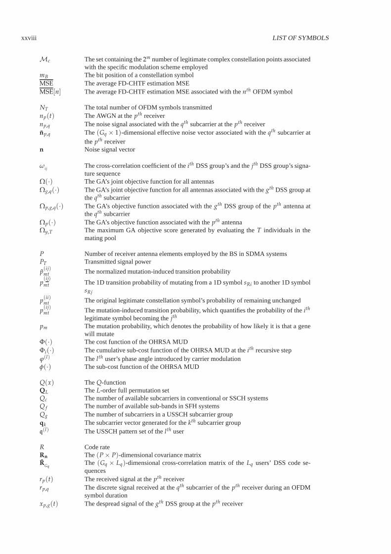
xxviii LIST OF SYMBOLS
Mc The set containing the2m number of legitimate complex constellation points associatedwith the specific modulation scheme employed
mB The bit position of a constellation symbolMSE The average FD-CHTF estimation MSEMSE[n] The average FD-CHTF estimation MSE associated with thenth OFDM symbol
NT The total number of OFDM symbols transmittednp(t) The AWGN at thepth receivernp,q The noise signal associated with theqth subcarrier at thepth receivernp,q The (Gq × 1)-dimensional effective noise vector associated with theqth subcarrier at
the pth receivern Noise signal vector
ωij
The cross-correlation coefficient of theith DSS group’s and thejth DSS group’s signa-ture sequence
Ω(·) The GA’s joint objective function for all antennasΩg,q(·) The GA’s joint objective function for all antennas associated with thegth DSS group at
theqth subcarrierΩp,g,q(·) The GA’s objective function associated with thegth DSS group of thepth antenna at
theqth subcarrierΩp(·) The GA’s objective function associated with thepth antennaΩy,T The maximum GA objective score generated by evaluating theT individuals in the
mating pool
P Number of receiver antenna elements employed by the BS in SDMA systemsPT Transmitted signal power
p(ij)mt The normalized mutation-induced transition probability
p(ij)
mt The 1D transition probability of mutating from a 1D symbolsRi to another 1D symbolsRj
p(ii)mt The original legitimate constellation symbol’s probability of remaining unchanged
p(ij)mt The mutation-induced transition probability, which quantifies the probability of theith
legitimate symbol becoming thejth
pm The mutation probability, which denotes the probability ofhow likely it is that a genewill mutate
Φ(·) The cost function of the OHRSA MUDΦi(·) The cumulative sub-cost function of the OHRSA MUD at theith recursive stepϕ(l) The lth user’s phase angle introduced by carrier modulationφ(·) The sub-cost function of the OHRSA MUD
Q(x) TheQ-functionQL TheL-order full permutation setQc The number of available subcarriers in conventional or SSCHsystemsQ f The number of available sub-bands in SFH systemsQg The number of subcarriers in a USSCH subcarrier groupqk The subcarrier vector generated for thekth subcarrier groupq(l) The USSCH pattern set of thelth user
R Code rateRn The(P × P)-dimensional covariance matrixR
GqThe (Gq × Lq)-dimensional cross-correlation matrix of theLq users’ DSS code se-quences
rp(t) The received signal at thepth receiverrp,q The discrete signal received at theqth subcarrier of thepth receiver during an OFDM
symbol durationxp,g(t) The despread signal of thegth DSS group at thepth receiver

LIST OF SYMBOLS xxix
s(l)i Theith constellation point ofMc as well as a possible gene symbol for thelth user
s′(l)gl ,q(t) The transmitted signal at theqth subcarrier associated with thelth user in thegth DSS
groups(l) The transmitted signal of thelth user at a subcarrier
s(l)gl ,q(t) The information signal at theqth subcarrier associated with thelth user in thegth DSS
groupsRi Theith 1D constellation symbol in the context of real axissq TheLq users’(Lq × 1)-dimensional information signal vectors The candidate trial vectorsi The sub-vector ofs at theith OHRSA recursive steps(l) The lth user’s estimated information symbol block of the FFT length
s(l)W The estimatedlth user’s WHT-despreading signal block
s(l)W,0 The estimatedlth user’s WHT-despread signal block
sGA The estimated transmitted symbol vector detected by the GA MUDsGAg,q The GA-based estimated(lg × 1)-dimensional signal vector associated with thegth
DSS group at theqth subcarriersMMSE g,q The MMSE-based estimated(lg × 1)-dimensional signal vector associated with the
gth DSS group at theqth subcarriers[n, k] The trial data vector of the GA-JCEMUDs(y,x) Thexth individual of theyth generations(y,x)[n, k] The symbol chromosome of the GA-JCEMUD individual associated with thexth indi-
vidual of theyth generations Transmitted signal vectors(l) The lth user’s information symbol block of the FFT length
s(l)W The lth user’s WHT-spread signal block
s(l)W,0 The lth user’s WHT-spreading signal block
sg The(lg × 1)-dimensional trial symbol vector for the GA’s objective function associatedwith thegth DSS group
s(l)(y,x)
[n, k] Thelth symbol gene of the GA-JCEMUD symbol chromosome associated with thexth
individual of theyth generationσ2
l Signal variance associated with thelth userσ2
n Noise variance
Th The FH dwell timeTC(n, k, K) Turbo convolutional codes with the number of input bitsk, the number of coded bitsn
and the constraint lengthKTr The reuse time interval of hopping patternsTc The DSS chip duration
UWHT K TheK-order WHT matrixugl
[c] The cth element of thegth row in the (G × G)-dimensional WHT matrix, which isassociated with thelth user
V The upper-triangular matrix having positive real-valued elements on the main diagonalν CM code memory
W System bandwidthWsc Subcarrier bandwidthWMMSE The MMSE-based weight matrixWMMSE g,q The MMSE-based(P × lg)-dimensional weight matrix associated with thegth DSS
group at theqth subcarrier
X GA population sizexp The received signal at thepth receiver at a subcarrier
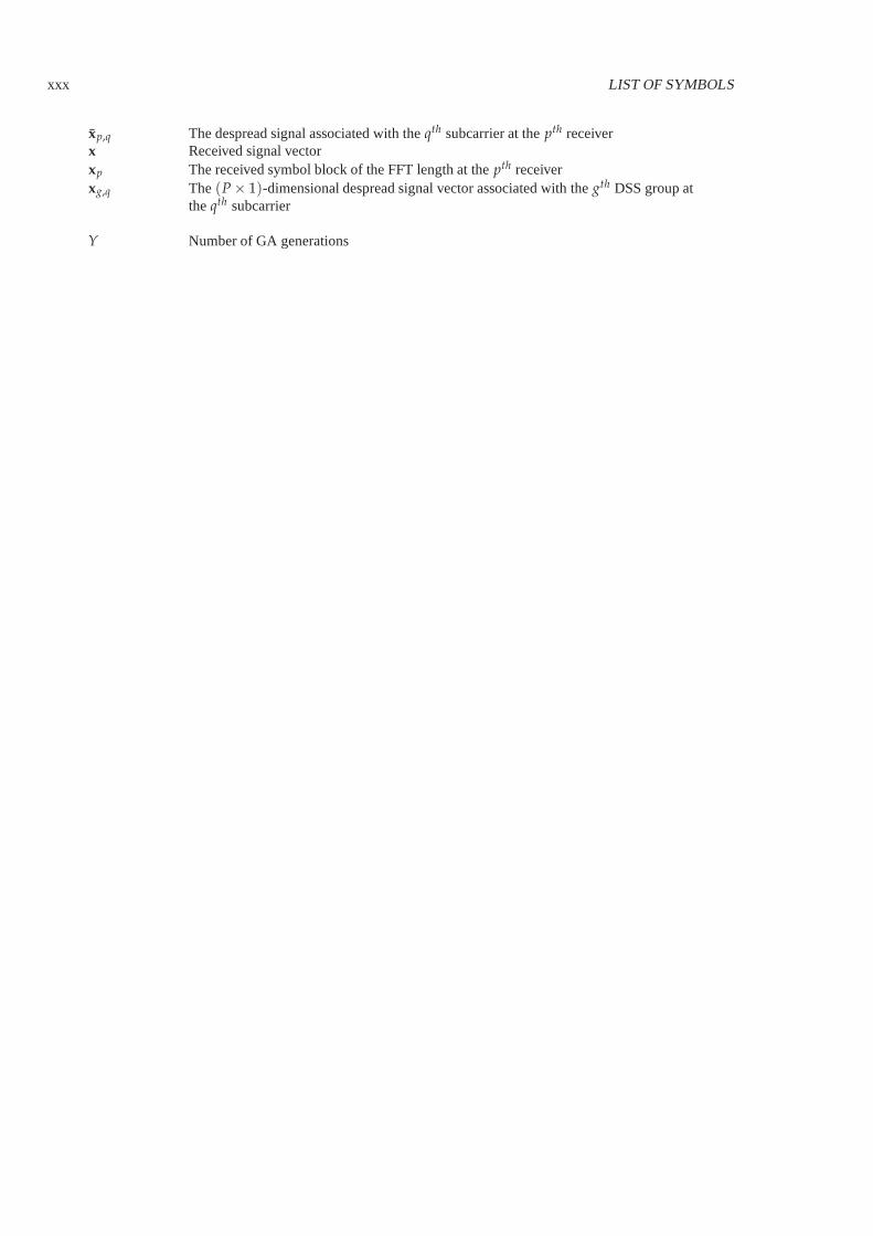
xxx LIST OF SYMBOLS
xp,q The despread signal associated with theqth subcarrier at thepth receiverx Received signal vectorxp The received symbol block of the FFT length at thepth receiverxg,q The(P × 1)-dimensional despread signal vector associated with thegth DSS group at
theqth subcarrier
Y Number of GA generations

Chapter1Introduction to OFDM and MIMO-OFDM
1.1 OFDM History
In recent years Orthogonal Frequency Division Multiplexing (OFDM) [3–6] has emerged as a successful air-interfacetechnique. In the context of wired environments, OFDM techniques are also known as Discrete MultiTone (DMT) [7]transmissions and are employed in the American National Standards Institute’s (ANSI) Asymmetric Digital Sub-scriber Line (ADSL) [8], High-bit-rate Digital SubscriberLine (HDSL) [9], and Very-high-speed Digital SubscriberLine (VDSL) [10] standards as well as in the European Telecommunication Standard Institute’s (ETSI) [11] VDSLapplications. In wireless scenarios, OFDM has been advocated by many European standards, such as Digital AudioBroadcasting (DAB) [12], Digital Video Broadcasting for Terrestrial television (DVB-T) [13], Digital Video Broad-casting for Handheld terminals (DVB-H) [14], Wireless Local Area Networks (WLANs) [15] and Broadband RadioAccess Networks (BRANs) [16]. Furthermore, OFDM has been ratified as a standard or has been considered as a can-didate standard by a number of standardization groups of theInstitute of Electrical and Electronics Engineers (IEEE),such as the IEEE 802.11 [17] and the IEEE 802.16 [18] standardfamilies.
The concept of parallel transmission of data over dispersive channels was first mentioned as early as 1957 in thepioneering contribution of Doelzet al. [19], while the first OFDM schemes date back in 1960s, which were proposedby Chang [20] and Saltzberg [21]. In the classic parallel data transmission systems [20, 21], the Frequency-Domain(FD) bandwidth is divided into a number of non-overlapping subchannels, each of which hosts a specific carrier widelyreferred to as a subcarrier. While each subcarrier is separately modulated by a data symbol, the overall modulationoperation across all the subchannels results in a frequency-multiplexed signal. All of the sinc-shaped subchannelspectra exhibit zero-crossings at all of the remaining subcarrier frequencies and the individual subchannel spectra areorthogonal to each other. This ensures that the subcarrier signals do not interfere with each other, when communicatingover perfectly distortionless channels, as a consequence of their orthogonality [5].
The early OFDM schemes [20–23] required banks of sinusoidalsubcarrier generators and demodulators, whichimposed a high implementation complexity. This drawback limited the application of OFDM to military systems until1971, when Weinstein and Ebert [24] suggested that the Discrete Fourier Transform (DFT) can be used for the OFDMmodulation and demodulation processes, which significantly reduces the implementation complexity of OFDM. Sincethen, more practical OFDM research has been carried out. Forexample, in the early 1980s Peled and Ruiz [25]proposed a simplified FD data transmission method using a cyclic prefix aided technique and exploited reduced-complexity algorithms for achieving a significantly lower computational complexity than that of classic single-carriertime-domain Quadrature Amplitude Modulation (QAM) [26] modems. Around the same era, Keasleret al. [27] in-vented a high-speed OFDM modem for employment in switched networks, such as the telephone network. Hirosakidesigned a subchannel-based equalizer for an orthogonallymultiplexed QAM system in 1980 [28] and later intro-duced the DFT-based implementation of OFDM systems [29], based on which a so-called groupband data modem wasdeveloped [30]. Cimini [31] and Kalet [32] investigated theperformance of OFDM modems in mobile communica-tion channels. Furthermore, Alard and Lassalle [33] applied OFDM in digital broadcasting systems, which was thepioneering work of the European DAB standard [12] established in the mid-1990s. More recent advances in OFDMtransmission were summarized in the state-of-the-art collection of works edited by Fazel and Fettweis [34]. Otherimportant recent OFDM references include the books by Hanzoet al. [5] and Van Neeet al. [6] as well as a numberof overview papers [35–37].
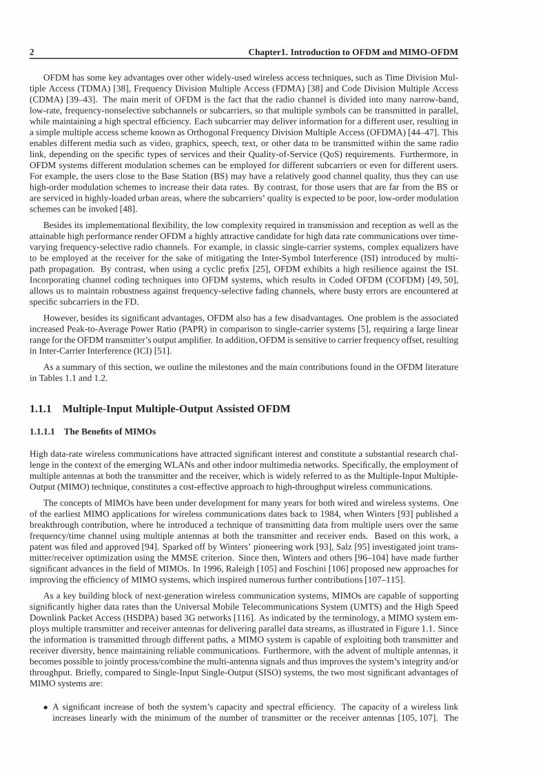
2 Chapter1. Introduction to OFDM and MIMO-OFDM
OFDM has some key advantages over other widely-used wireless access techniques, such as Time Division Mul-tiple Access (TDMA) [38], Frequency Division Multiple Access (FDMA) [38] and Code Division Multiple Access(CDMA) [39–43]. The main merit of OFDM is the fact that the radio channel is divided into many narrow-band,low-rate, frequency-nonselective subchannels or subcarriers, so that multiple symbols can be transmitted in parallel,while maintaining a high spectral efficiency. Each subcarrier may deliver information for a different user, resulting ina simple multiple access scheme known as Orthogonal Frequency Division Multiple Access (OFDMA) [44–47]. Thisenables different media such as video, graphics, speech, text, or other data to be transmitted within the same radiolink, depending on the specific types of services and their Quality-of-Service (QoS) requirements. Furthermore, inOFDM systems different modulation schemes can be employed for different subcarriers or even for different users.For example, the users close to the Base Station (BS) may havea relatively good channel quality, thus they can usehigh-order modulation schemes to increase their data rates. By contrast, for those users that are far from the BS orare serviced in highly-loaded urban areas, where the subcarriers’ quality is expected to be poor, low-order modulationschemes can be invoked [48].
Besides its implementational flexibility, the low complexity required in transmission and reception as well as theattainable high performance render OFDM a highly attractive candidate for high data rate communications over time-varying frequency-selective radio channels. For example,in classic single-carrier systems, complex equalizers haveto be employed at the receiver for the sake of mitigating the Inter-Symbol Interference (ISI) introduced by multi-path propagation. By contrast, when using a cyclic prefix [25], OFDM exhibits a high resilience against the ISI.Incorporating channel coding techniques into OFDM systems, which results in Coded OFDM (COFDM) [49, 50],allows us to maintain robustness against frequency-selective fading channels, where busty errors are encountered atspecific subcarriers in the FD.
However, besides its significant advantages, OFDM also has afew disadvantages. One problem is the associatedincreased Peak-to-Average Power Ratio (PAPR) in comparison to single-carrier systems [5], requiring a large linearrange for the OFDM transmitter’s output amplifier. In addition, OFDM is sensitive to carrier frequency offset, resultingin Inter-Carrier Interference (ICI) [51].
As a summary of this section, we outline the milestones and the main contributions found in the OFDM literaturein Tables 1.1 and 1.2.
1.1.1 Multiple-Input Multiple-Output Assisted OFDM
1.1.1.1 The Benefits of MIMOs
High data-rate wireless communications have attracted significant interest and constitute a substantial research chal-lenge in the context of the emerging WLANs and other indoor multimedia networks. Specifically, the employment ofmultiple antennas at both the transmitter and the receiver,which is widely referred to as the Multiple-Input Multiple-Output (MIMO) technique, constitutes a cost-effective approach to high-throughput wireless communications.
The concepts of MIMOs have been under development for many years for both wired and wireless systems. Oneof the earliest MIMO applications for wireless communications dates back to 1984, when Winters [93] published abreakthrough contribution, where he introduced a technique of transmitting data from multiple users over the samefrequency/time channel using multiple antennas at both thetransmitter and receiver ends. Based on this work, apatent was filed and approved [94]. Sparked off by Winters’ pioneering work [93], Salz [95] investigated joint trans-mitter/receiver optimization using the MMSE criterion. Since then, Winters and others [96–104] have made furthersignificant advances in the field of MIMOs. In 1996, Raleigh [105] and Foschini [106] proposed new approaches forimproving the efficiency of MIMO systems, which inspired numerous further contributions [107–115].
As a key building block of next-generation wireless communication systems, MIMOs are capable of supportingsignificantly higher data rates than the Universal Mobile Telecommunications System (UMTS) and the High SpeedDownlink Packet Access (HSDPA) based 3G networks [116]. As indicated by the terminology, a MIMO system em-ploys multiple transmitter and receiver antennas for delivering parallel data streams, as illustrated in Figure 1.1. Sincethe information is transmitted through different paths, a MIMO system is capable of exploiting both transmitter andreceiver diversity, hence maintaining reliable communications. Furthermore, with the advent of multiple antennas, itbecomes possible to jointly process/combine the multi-antenna signals and thus improves the system’s integrity and/orthroughput. Briefly, compared to Single-Input Single-Output (SISO) systems, the two most significant advantages ofMIMO systems are:
• A significant increase of both the system’s capacity and spectral efficiency. The capacity of a wireless linkincreases linearly with the minimum of the number of transmitter or the receiver antennas [105, 107]. The
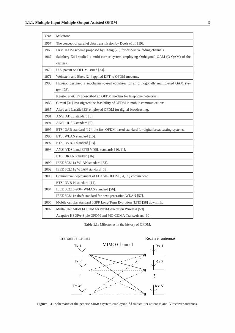
1.1.1. Multiple-Input Multiple-Output Assisted OFDM 3
Year Milestone
1957 The concept of parallel data transmission by Doelzet al. [19].
1966 First OFDM scheme proposed by Chang [20] for dispersive fading channels.
1967 Saltzberg [21] studied a multi-carrier system employing Orthogonal QAM (O-QAM) of the
carriers.
1970 U.S. patent on OFDM issued [23].
1971 Weinstein and Ebert [24] applied DFT to OFDM modems.
1980 Hirosaki designed a subchannel-based equalizer for an orthogonally multiplexed QAM sys-
tem [28].
Keasleret al. [27] described an OFDM modem for telephone networks.
1985 Cimini [31] investigated the feasibility of OFDM in mobile communications.
1987 Alard and Lasalle [33] employed OFDM for digital broadcasting.
1991 ANSI ADSL standard [8].
1994 ANSI HDSL standard [9].
1995 ETSI DAB standard [12]: the first OFDM-based standard for digital broadcasting systems.
1996 ETSI WLAN standard [15].
1997 ETSI DVB-T standard [13].
1998 ANSI VDSL and ETSI VDSL standards [10,11].
ETSI BRAN standard [16].
1999 IEEE 802.11a WLAN standard [52].
2002 IEEE 802.11g WLAN standard [53].
2003 Commercial deployment of FLASH-OFDM [54,55] commenced.
ETSI DVB-H standard [14].
2004 IEEE 802.16-2004 WMAN standard [56].
IEEE 802.11n draft standard for next generation WLAN [57].
2005 Mobile cellular standard 3GPP Long-Term Evolution (LTE) [58] downlink.
2007 Multi-User MIMO-OFDM for Next-Generation Wireless [59]
Adaptive HSDPA-Style OFDM and MC-CDMA Transceivers [60].
Table 1.1: Milestones in the history of OFDM.
……
MIMO Channel Tx 1
Tx 2
Tx M
Rx 1
Rx 2
Rx N
Transmit antennas Receiver antennas
Figure 1.1: Schematic of the generic MIMO system employingM transmitter antennas andN receiver antennas.
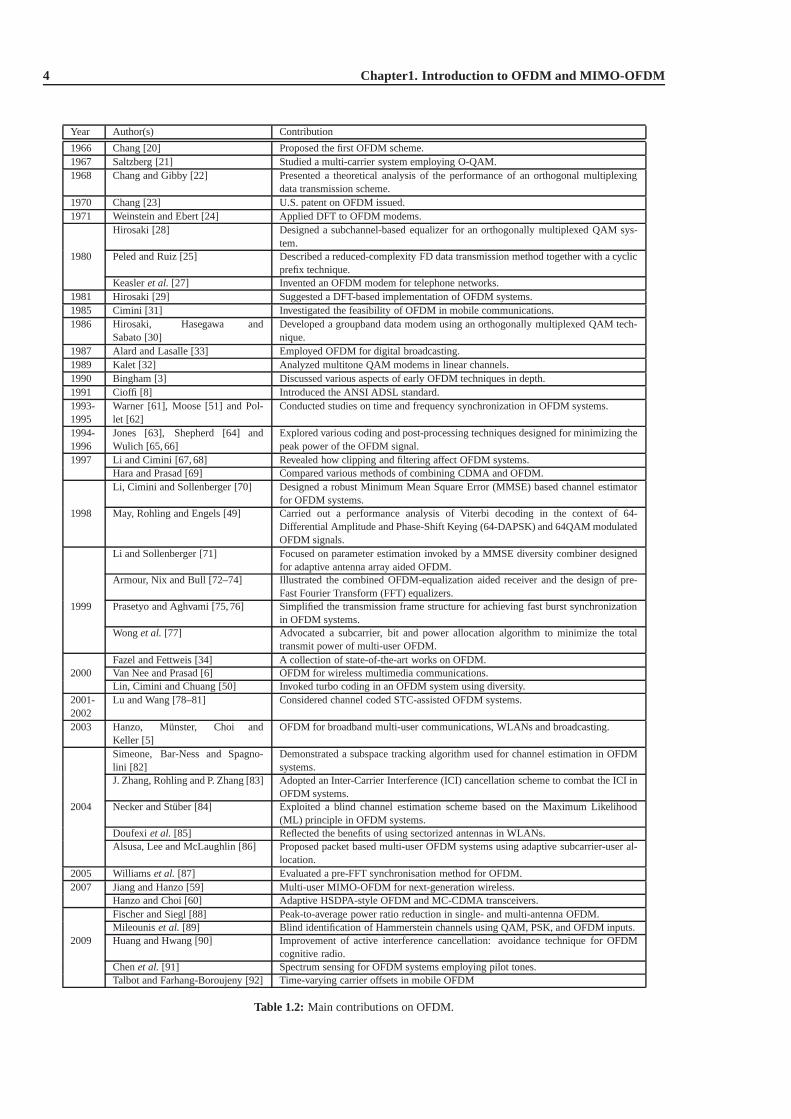
4 Chapter1. Introduction to OFDM and MIMO-OFDM
Year Author(s) Contribution
1966 Chang [20] Proposed the first OFDM scheme.1967 Saltzberg [21] Studied a multi-carrier system employing O-QAM.1968 Chang and Gibby [22] Presented a theoretical analysis of the performance of an orthogonal multiplexing
data transmission scheme.1970 Chang [23] U.S. patent on OFDM issued.1971 Weinstein and Ebert [24] Applied DFT to OFDM modems.
Hirosaki [28] Designed a subchannel-based equalizer for an orthogonallymultiplexed QAM sys-tem.
1980 Peled and Ruiz [25] Described a reduced-complexity FD data transmission method together with a cyclicprefix technique.
Keasleret al. [27] Invented an OFDM modem for telephone networks.1981 Hirosaki [29] Suggested a DFT-based implementation of OFDM systems.1985 Cimini [31] Investigated the feasibility of OFDM in mobile communications.1986 Hirosaki, Hasegawa and
Sabato [30]Developed a groupband data modem using an orthogonally multiplexed QAM tech-nique.
1987 Alard and Lasalle [33] Employed OFDM for digital broadcasting.1989 Kalet [32] Analyzed multitone QAM modems in linear channels.1990 Bingham [3] Discussed various aspects of early OFDM techniques in depth.1991 Cioffi [8] Introduced the ANSI ADSL standard.1993-1995
Warner [61], Moose [51] and Pol-let [62]
Conducted studies on time and frequency synchronization inOFDM systems.
1994-1996
Jones [63], Shepherd [64] andWulich [65, 66]
Explored various coding and post-processing techniques designed for minimizing thepeak power of the OFDM signal.
1997 Li and Cimini [67, 68] Revealed how clipping and filtering affect OFDM systems.Hara and Prasad [69] Compared various methods of combining CDMA and OFDM.Li, Cimini and Sollenberger [70] Designed a robust Minimum Mean Square Error (MMSE) based channel estimator
for OFDM systems.1998 May, Rohling and Engels [49] Carried out a performance analysis of Viterbi decoding in the context of 64-
Differential Amplitude and Phase-Shift Keying (64-DAPSK)and 64QAM modulatedOFDM signals.
Li and Sollenberger [71] Focused on parameter estimation invoked by a MMSE diversitycombiner designedfor adaptive antenna array aided OFDM.
Armour, Nix and Bull [72–74] Illustrated the combined OFDM-equalization aided receiver and the design of pre-Fast Fourier Transform (FFT) equalizers.
1999 Prasetyo and Aghvami [75, 76] Simplified the transmission frame structure for achieving fast burst synchronizationin OFDM systems.
Wonget al. [77] Advocated a subcarrier, bit and power allocation algorithmto minimize the totaltransmit power of multi-user OFDM.
Fazel and Fettweis [34] A collection of state-of-the-art works on OFDM.2000 Van Nee and Prasad [6] OFDM for wireless multimedia communications.
Lin, Cimini and Chuang [50] Invoked turbo coding in an OFDM system using diversity.2001-2002
Lu and Wang [78–81] Considered channel coded STC-assisted OFDM systems.
2003 Hanzo, Munster, Choi andKeller [5]
OFDM for broadband multi-user communications, WLANs and broadcasting.
Simeone, Bar-Ness and Spagno-lini [82]
Demonstrated a subspace tracking algorithm used for channel estimation in OFDMsystems.
J. Zhang, Rohling and P. Zhang [83] Adopted an Inter-Carrier Interference (ICI) cancellationscheme to combat the ICI inOFDM systems.
2004 Necker and Stuber [84] Exploited a blind channel estimation scheme based on the Maximum Likelihood(ML) principle in OFDM systems.
Doufexi et al. [85] Reflected the benefits of using sectorized antennas in WLANs.Alsusa, Lee and McLaughlin [86] Proposed packet based multi-user OFDM systems using adaptive subcarrier-user al-
location.2005 Williams et al. [87] Evaluated a pre-FFT synchronisation method for OFDM.2007 Jiang and Hanzo [59] Multi-user MIMO-OFDM for next-generation wireless.
Hanzo and Choi [60] Adaptive HSDPA-style OFDM and MC-CDMA transceivers.Fischer and Siegl [88] Peak-to-average power ratio reduction in single- and multi-antenna OFDM.Mileouniset al. [89] Blind identification of Hammerstein channels using QAM, PSK, and OFDM inputs.
2009 Huang and Hwang [90] Improvement of active interference cancellation: avoidance technique for OFDMcognitive radio.
Chenet al. [91] Spectrum sensing for OFDM systems employing pilot tones.Talbot and Farhang-Boroujeny [92] Time-varying carrier offsets in mobile OFDM
Table 1.2: Main contributions on OFDM.

1.1.1. Multiple-Input Multiple-Output Assisted OFDM 5
data rate can be increased by spatial multiplexing without consuming more frequency resources and withoutincreasing the total transmit power.
• Dramatic reduction of the effects of fading due to the increased diversity. This is particularly beneficial, whenthe different channels fade independently.
An overview of MIMO techniques covering channel models, performance limits, coding and transceiver designs canbe found in [117].
1.1.1.2 MIMO OFDM
The quality of a wireless link can be described by three basicparameters, namely the transmission rate, the transmis-sion range and the transmission reliability. Conventionally, the transmission rate may be increased by reducing thetransmission range and reliability. By contrast, the transmission range may be extended at the cost of a lower trans-mission rate and reliability, while the transmission reliability may be improved by reducing the transmission rate andrange [118]. However, with the advent of MIMO assisted OFDM systems, the above-mentioned three parameters maybe simultaneously improved [118]. Initial field tests of broadband wireless MIMO-OFDM communication systemshave shown that an increased capacity, coverage and reliability is achievable with the aid of MIMO techniques [119].Furthermore, although MIMOs can potentially be combined with any modulation or multiple access technique, recentresearch suggests that the implementation of MIMO aided OFDM is more efficient, as a benefit of the straightforwardmatrix algebra invoked for processing the MIMO OFDM signals[118].
MIMO OFDM, which is claimed to be invented by Airgo Networks [120], has formed the foundation of all candi-date standards proposed for IEEE 802.11n [121]. In recent years, this topic has attracted substantial research efforts,addressing numerous aspects, such as system capacity [122,123], space/time/frequency coding [124–128], Peak-to-Average Power Ratio (PAPR) control [129–131], channel estimation [132–134], receiver design [135–138], etc. Re-cently, Paulrajet al. [117] and Stuberet al. [139] provided compelling overviews of MIMO OFDM communications.Furthermore, Nortel Networks has developed a MIMO OFDM prototype [140] during late 2004, which demonstratesthe superiority of MIMO OFDM over today’s networks in terms of the achievable data rate. For the reader’s conve-nience, we have summarized the major contributions on MIMO OFDM in Tables 1.3, 1.4 and 1.5 at a glance.
1.1.1.3 SDMA-based MIMO OFDM Systems
As a subclass of MIMO arrangements, recently the Space Division Multiple Access (SDMA) [5, 194–196] basedtechniques have attracted substantial interest. As one of the most promising techniques aiming at solving the ca-pacity problem of wireless communication systems, SDMA enables multiple users to simultaneously share the samebandwidth in different geographical locations. More specifically, the exploitation of the spatial dimension, namelythe so-called spatial signature, makes it possible to identify the individual users, even when they are in the sametime/frequency/code domains, thus increasing the system’s capacity.
In Figure 1.2 we illustrate the concept of SDMA systems. As shown in Figure 1.2, each user exploiting a singletransmitter antenna aided Mobile Station (MS) simultaneously communicates with the BS equipped with an array ofreceiver antennas. Explicitly, SDMA can be considered as a specific branch of the family of MIMO systems, wherethe transmissions of the multiple transmitter antennas cannot be coordinated, simply because they belong to differentusers. Briefly speaking, the major advantages of SDMA techniques are [197]:
• Range extension: With the aid of antenna array, the coverage area of high-integrity reception can be significantlylarger than that of any single-antenna aided systems. In a SDMA system, the number of cells required forcovering a given geographic area can be substantially reduced. For example, a ten-element array offers a gainof ten, which typically doubles the radius of the cell and hence quadruples the coverage area.
• Multi-path mitigation: Benefitting from the MIMO architecture, in SDMA systems thedetrimental effects ofmulti-path propagations are effectively mitigated. Furthermore, in specific scenarios the multi-path phenomenoncan even be exploited for enhancing the desired users’ signals by employing efficient receiver diversity schemes.
• Capacity increase: Theoretically, SDMA can be incorporated into any existingmultiple access standard at thecost of a limited increase in system complexity, while attaining a substantial increase in capacity. For instance,by applying SDMA to a conventional TDMA system, two or more users can share the same time slots, resultingin a doubled or higher overall system capacity.

6 Chapter1. Introduction to OFDM and MIMO-OFDM
Year Author(s) Contribution
Piechockiet al. [141] Reported on the performance benefits of spatial multiplexing using ML decoding for a Vertical
Bell Labs Layered Space-Time (V-BLAST) OFDM system.
2001 Blum, Li, Winters and
Yan [124]
Studied improved space-time coding techniques for MIMO OFDM systems.
Li [132] Exploited optimum training sequence design and simplified channel estimation for improving the
performance and for reducing the complexity of channel parameter estimation in MIMO OFDM
systems.
Bolckei, Gesbert and
Paulraj [122]
Analyzed the influence of physical parameters such as the amount of delay spread, cluster angle
spread and total angle spread, as well as system parameters such as the number of antennas and
the antenna spacing on both the ergodic capacity and outage capacity.
Catreuxet al. [142] Offered an overview of the challenges and promises of link adaptation in future broadband wire-
less networks.
2002 Piechockiet al. [143] Presented a performance evaluation of spatial multiplexing and space-frequency coded modula-
tion schemes designed for WLANs.
Molisch, Win and Win-
ters [144]
Proposed a reduced-complexity method for grouping multiple antennas and space-time codes.
Li, Winters and Sollen-
berger [135]
Invoked space-time coding and Successive Interference Cancellation (SIC) in MIMO OFDM
systems.
Stamouliset al. [145] Revealed the effects of ICI on MIMO-OFDM.
Doufexi et al. [146] Characterized the outdoor physical layer performance of a coded MIMO OFDM system using
space-time processing.
Giangasperoet al. [136] Compared two Co-Channel Interference (CCI) cancellation schemes in the context of MIMO
OFDM.
Li, Letaief and Cao [137] Advocated a CCI cancellation method using angle diversity based on null-steering or minimum
variance distortion response beamforming.
Bolcskei, Borgmann and
Paulraj [147]
Measured the impact of the propagation environment on the performance of space-frequency
coded MIMO OFDM.
Barhumi, Leus and Moo-
nen [133]
Described a Least-Squares (LS) channel estimation scheme designed for MIMO OFDM systems
based on pilot tones.
Ganesan and Say-
eed [123]
Derived a virtual MIMO framework for single-transmitter, single-receiver multipath fading chan-
nels that enables maximal exploitation of channel diversity at both the transmitter and the re-
ceiver.
2003 Gamalet al. [125] Utilized an OFDM technique to transform the MIMO multi-pathchannel into a MIMO flat block
fading channel, where the associated diversity is exploited by employing space-frequency codes.
Moon et al. [129] Evaluated the PAPR performance in a MIMO OFDM-based WLAN system using a Space-Time
Block Code (STBC).
Cai, Song and Li [148] Developed a technique based on the auto-correlation function for estimating the Doppler spread
in Rayleigh fading channels for mobile OFDM systems using multiple antennas.
Leus and Moonen [149] Employed tone-by-tone based equalization techniques in MIMO OFDM systems.
Leeet al. [130] Investigated the PAPR characteristics in a MIMO OFDM systemusing the selective mapping
approach.
Piechockiet al. [150] Devised a blind method for joint detection of space-time coded MIMO OFDM.
Table 1.3: Main contributions on MIMO OFDM (Part 1).

1.2. OFDM Schematic 7
Year Author(s) Contribution
Shin, H. Lee and C.
Lee [134]
Suggested a cyclic comb-type training structure for reducing the Mean-Square Errors (MSEs) at
the edge subcarriers of MIMO OFDM signals.
Xia, Zhou and Gian-
nakis [151]
Created an adaptive MIMO OFDM transmitter by applying an adaptive two-dimensional coder-
beamformer with the aid of partial channel knowledge.
Huang and Letaief [152] Portrayed an OFDM symbol based space diversity technique.
Butler and Collings [153] Employed an approximate log-likelihood decoding approachbased on a Zero-Forcing (ZF) re-
ceiver for bit-interleaved coded modulation assisted MIMOOFDM systems.
Stuberet al. [139] Summarized various physical layer research challenges in MIMO-OFDM system design.
Paulrajet al. [117] Provided an overview of MIMO and/or MIMO OFDM systems.
Lu, Yue and Wang [154] Identified the performance of an optimized MIMO OFDM scheme using Low Density Parity
Check (LDPC) codes.
Van Zelst and
Schenk [155]
Implemented MIMO OFDM processing and evaluated its performance by both simulations and
experimental test results.
Pascual-Iserte, Perez-
Neira and Lagunas [156]
Conducted studies on maximizing the Signal to Noise and Interference Ratio (SNIR) over the
subcarriers subject to a total transmit power constraint.
2004 Zeng and Ng [157] Contrived a subspace-based semi-blind method for estimating the channel responses of a multi-
user and multi-antenna OFDM uplink system.
Alien et al. [158] Assessed the performance of spatial diversity in an OFDM WLAN for various antenna topolo-
gies.
Dayal, Brehler and
Varanasi [126]
Introduced space-time channel-sounding training codes designed for multiple-antenna, nonco-
herent, multiple block Rayleigh fading channel.
Park and Kang [138] Adopted a reduced-complexity iterative algorithm for joint Maximum-A-Posteriori (MAP) de-
tection and CCI suppression in MIMO OFDM systems.
Tan and Stuber [159] Combined cyclic delay diversity and MIMO OFDM for achievingfull spatial diversity in flat-
fading channels.
Wang, Shayan and
Zeng [160]
Illustrated the diversity and coding advantages in terms ofthe minimum Hamming distance and
the minimum squared product distance of the code as well as the relative frequencies.
Pan, Letaief and
Cao [161]
Discussed dynamic spatial subchannel allocation in conjunction with adaptive beamforming in
broadband OFDM wireless systems.
Tepedelenlioglu and
Challagulla [162]
Demonstrated how to achieve high diversity gains in MIMO OFDM systems with the aid of
fractional sampling.
Baeket al. [163] Addressed a time-domain semi-blind channel estimation approach and a PAPR Reduction
scheme for MIMO OFDM.
Dubucet al. [140] Outlined Nortel Networks’ MIMO OFDM concept prototype and provided measured perfor-
mance results.
Barriac and Mad-
how [164]
Offered guidelines for optimizing the antenna spacing in MIMO OFDM systems using feedback
of the covariance matrix of the downlink channel.
Table 1.4: Main contributions on MIMO OFDM (Part 2).
• Interference suppression: The interference imposed by other systems and by users in other cells can be signifi-cantly reduced by exploiting the desired user’s unique, user-specific Channel Impulse Responses (CIRs).
• Compatibility: SDMA is compatible with most of the existing modulation schemes, carrier frequencies andother specifications. Furthermore, it can be readily implemented using various array geometries and antennatypes.
The combination of SDMA and OFDM results in SDMA-OFDM systems [5, 194, 198, 199], which exploit themerits of both SDMA and OFDM, having attracted more and more interest [199–204]. Tables 1.6 and 1.7 summarizethe main contributions on SDMA and SDMA-OFDM found in the open literature.
1.2 OFDM Schematic
In this section we briefly introduce Orthogonal Frequency Division Multiplexing (OFDM) as a means of dealing withthe problems of frequency selective fading encountered, when transmitting over a high-rate wideband radio channel.
In the OFDM scheme of Figure 1.3 the serial data stream of a traffic channel is passed through a serial-to-parallelconvertor, which splits the data into a number of parallel sub-channels. The data in each sub-channel are applied

8 Chapter1. Introduction to OFDM and MIMO-OFDM
Year Author(s) Contribution
Su, Safar and Liu [127,128]
Designed a general space-frequency block code structure capable of providing full-rate, full-diversity MIMO OFDM transmission.
Zhang, Kavcic andWong [165]
Researched an optimal QR decomposition technique designedfor a precoded MIMO OFDMsystem using successive-cancellation detection.
Yao and Giannakis [166] Proposed a low-complexity blind Carrier Frequency Offset (CFO) estimator for OFDM systems.Zhenget al. [167] Extended Time-Division Synchronous CDMA (TD-SCDMA) to Time-Division Code-Division
Multiplexing OFDM (TD-CDM-OFDM) for future 4G systems.Yang [168] Reviewed the state-of-the-art approaches in MIMO OFDM air-interface.Zhang and Letaief [169] Aimed at developing an adaptive resource-allocation approach which jointly allocates subcarri-
ers, power and bits for multi-user MIMO OFDM systems.Ma [170] Established a pilot-assisted modulation scheme for CFO andchannel estimation in OFDM trans-
missions over frequency-selective MIMO fading channels.Fozunbal, McLaughlinand Schafer [171]
Calculated a sphere packing lower bound and a pairwise errorupper bound of the error probabil-ity of space-time-frequency coded OFDM systems using multiple antennas for transmission overblock-fading channels.
Nandaet al. [172] Built a MIMO WLAN prototype that provides data rates over 200Mb/s.Kim et al. [173] Invoked a QR-Decomposition combined with the M-algorithm (QRD-M) for joint data detection
and channel estimation in MIMO OFDM.Qiaoet al. [174] Contrived an iterative LS channel estimation algorithm forMIMO OFDM.Sampath, Erceg andPaulraj [175]
Validated the properties of the transmit correlation matrix through field trial results obtained froma MIMO OFDM wireless system operated in a macro-cellular environment.
Rey, Lamarca andVazquez [176]
Used a Bayesian approach to design transmit prefiltering matrices for closed-loop schemes,which is robust to channel estimation errors.
2005 Sun, Xiong andWang [177]
Targeted at designing CFO estimator aided Expectation Maximization (EM) based iterative re-ceivers for MIMO OFDM systems.
Han and Lee [131] Provided an overview of PAPR reduction techniques for multicarrier transmission.Lodhi et al. [178] Evaluated the complexity and performance of a Multi-Carrier Code-Division Multiple-Access
(MC-CDMA) system exploiting STBCs and Cyclic Delay Diversity (CDD).Wang, Han and Liu [179] Advanced MIMO OFDM channel estimation using a scheme based on estimating the Time-of-
Arrivals (TOAs).Wen, Wang andChen [180]
Reported on a low-complexity multi-user angle-frequency coding scheme based on the Fourierbasis structure for downlink wireless systems.
Su, Safar and Liu [181] Performance analysis of MIMO OFDM systems invoking coding in spatial, temporal and fre-quency domains.
Tan, Latinovic and Bar-Ness [182]
Advocated a scheme of cross-antenna rotation and inversionutilizing additional degrees of free-dom by employing multiple antennas in OFDM systems.
Park and Cho [183] Characterized a MIMO OFDM technique based on the weighting factor optimization for reduc-ing the ICI caused by time-varying channels.
Shao and Roy [184] Maximized the diversity gain achieved over frequency-selective channels by employing a full-rate space-frequency block code for MIMO OFDM systems.
Schenket al. [185] Quantified how the transmitter/receiver phase noise affects the performance of a MIMO OFDMsystem.
Borgmann andBolcskei [186]
Contributed to the code designs for noncoherent frequency-selective MIMO OFDM fading links.
Tarighat and Sayed [187] Examined the effect of IQ imbalances on MIMO OFDM systems anddeveloped a digital signalprocessing framework for combating these distortions.
Jiang, Li and Hager [188] Formulated a joint transceiver design combining the Geometric Mean Decomposition (GMD)with ZF-type decoders.
Choi and Heath [189] Constructed a limited feedback architecture that combinesbeamforming vector quantization andsmart vector interpolation.
Baeket al. [190] Incorporated multiple antennas into high-rate DAB systems.2007 Jiang and Hanzo [59] Reduced-complexity Near-ML SDMA-MUDs and joint iterativechannel estimation.
Hanzo and Choi [60] Near-instantaneously adaptive HSPA-style OFDM and MC-CDMA transceivers.Fischer and Siegl [88] Peak-to-average power ratio reduction in single- and multi-antenna OFDM.Fakhereddinet al. [191] Reduced feedback and random beamforming for OFDM MIMO.
2009 Deet al. [192] Linear prediction based semiblind channel estimation for multiuser OFDM.Haringet al. [193] Fine frequency synchronization in the uplink of multiuser OFDM systems.
Table 1.5: Main contributions on MIMO OFDM (Part 3).

1.2. OFDM Schematic 9
BS
MS 1
MS 2
MS L
P-element antenna array
…
Figure 1.2: Illustration of the generic SDMA system employing aP-element receiver antenna array for supportingLnumber of mobile users.
Tx1
Tx2
TxM
Source
v[ bits
]
-
×
6f0
×
6
×
6
2 f0
M f0
vM [ bit
s ]
vM [ bit
s ]
vM [ bit
s ]
modulators
Subch1
Subch2
SubchM
×
6f0
×
6
×
6
2 f0
M f0
Rx1
Rx2
RxM
demodulators
v[ bits
]
- Sink
Channel
Figure 1.3: Simplified blockdiagram of the orthogonal parallel modem
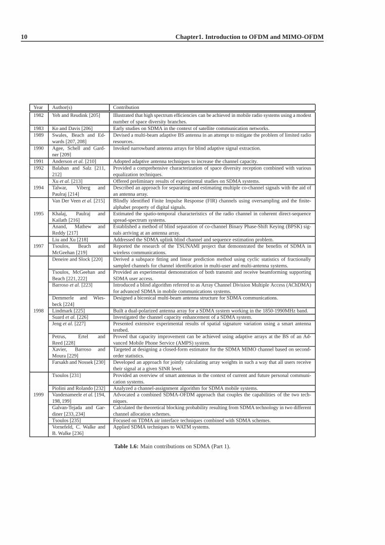
10 Chapter1. Introduction to OFDM and MIMO-OFDM
Year Author(s) Contribution
1982 Yeh and Reudink [205] Illustrated that high spectrum efficiencies can be achievedin mobile radio systems using a modestnumber of space diversity branches.
1983 Ko and Davis [206] Early studies on SDMA in the context of satellite communication networks.1989 Swales, Beach and Ed-
wards [207, 208]Devised a multi-beam adaptive BS antenna in an attempt to mitigate the problem of limited radioresources.
1990 Agee, Schell and Gard-ner [209]
Invoked narrowband antenna arrays for blind adaptive signal extraction.
1991 Andersonet al. [210] Adopted adaptive antenna techniques to increase the channel capacity.1992 Balaban and Salz [211,
212]Provided a comprehensive characterization of space diversity reception combined with variousequalization techniques.
Xu et al. [213] Offered preliminary results of experimental studies on SDMA systems.1994 Talwar, Viberg and
Paulraj [214]Described an approach for separating and estimating multiple co-channel signals with the aid ofan antenna array.
Van Der Veenet al. [215] Blindly identified Finite Impulse Response (FIR) channels using oversampling and the finite-alphabet property of digital signals.
1995 Khalaj, Paulraj andKailath [216]
Estimated the spatio-temporal characteristics of the radio channel in coherent direct-sequencespread-spectrum systems.
Anand, Mathew andReddy [217]
Established a method of blind separation of co-channel Binary Phase-Shift Keying (BPSK) sig-nals arriving at an antenna array.
Liu and Xu [218] Addressed the SDMA uplink blind channel and sequence estimation problem.1997 Tsoulos, Beach and
McGeehan [219]Reported the research of the TSUNAMI project that demonstrated the benefits of SDMA inwireless communications.
Deneire and Slock [220] Derived a subspace fitting and linear prediction method using cyclic statistics of fractionallysampled channels for channel identification in multi-user and multi-antenna systems.
Tsoulos, McGeehan andBeach [221, 222]
Provided an experimental demonstration of both transmit and receive beamforming supportingSDMA user access.
Barrosoet al. [223] Introduced a blind algorithm referred to as Array Channel Division Multiple Access (AChDMA)for advanced SDMA in mobile communications systems.
Demmerle and Wies-beck [224]
Designed a biconical multi-beam antenna structure for SDMAcommunications.
1998 Lindmark [225] Built a dual-polarized antenna array for a SDMA system working in the 1850-1990MHz band.Suardet al. [226] Investigated the channel capacity enhancement of a SDMA system.Jenget al. [227] Presented extensive experimental results of spatial signature variation using a smart antenna
testbed.Petrus, Ertel andReed [228]
Proved that capacity improvement can be achieved using adaptive arrays at the BS of an Ad-vanced Mobile Phone Service (AMPS) system.
Xavier, Barroso andMoura [229]
Targeted at designing a closed-form estimator for the SDMA MIMO channel based on second-order statistics.
Farsakh and Nossek [230] Developed an approach for jointly calculating array weights in such a way that all users receivetheir signal at a given SINR level.
Tsoulos [231] Provided an overview of smart antennas in the context of current and future personal communi-cation systems.
Piolini and Rolando [232] Analyzed a channel-assignment algorithm for SDMA mobile systems.1999 Vandenameeleet al. [194,
198, 199]Advocated a combined SDMA-OFDM approach that couples the capabilities of the two tech-niques.
Galvan-Tejada and Gar-diner [233, 234]
Calculated the theoretical blocking probability resulting from SDMA technology in two differentchannel allocation schemes.
Tsoulos [235] Focused on TDMA air interface techniques combined with SDMAschemes.Vornefeld, C. Walke andB. Walke [236]
Applied SDMA techniques to WATM systems.
Table 1.6: Main contributions on SDMA (Part 1).
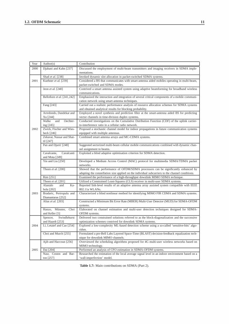
1.2. OFDM Schematic 11
Year Author(s) Contribution
2000 Djahani and Kahn [237] Discussed the employment of multi-beam transmitters and imaging receivers in SDMA imple-mentations.
Shadet al. [238] Invoked dynamic slot allocation in packet-switched SDMA systems.2001 Kuehneret al. [239] Considered a BS that communicates with smart-antenna aidedmobiles operating in multi-beam,
packet-switched and SDMA modes.Jeonet al. [240] Contrived a smart antenna assisted system using adaptive beamforming for broadband wireless
communications.Bellofioreet al.[241,242] Emphasized the interaction and integration of several critical components of a mobile communi-
cation network using smart-antenna techniques.Fang [243] Carried out a realistic performance analysis of resource allocation schemes for SDMA systems
and obtained analytical results for blocking probability.Arredondo, Dandekar andXu [244]
Employed a novel synthesis and prediction filter at the smart-antenna aided BS for predictingvector channels in time-division duplex systems.
Walke and Oechter-ing [245]
Conducted investigations on the Cumulative Dstribution Function (CDF) of the uplink carrier-to-interference ratio in a cellular radio network.
2002 Zwick, Fischer and Wies-beck [246]
Proposed a stochastic channel model for indoor propagations in future communication systemsequipped with multiple antennas.
Zekavat, Nassar and Shat-til [247]
Combined smart antenna arrays and MC-CDMA systems.
Pan and Djuric [248] Suggested sectorized multi-beam cellular mobile communications combined with dynamic chan-nel assignment to beams.
Cavalcante, Cavalcantiand Mota [249]
Exploited a blind adaptive optimisation criterion for SDMAdetection.
Yin and Liu [250] Developed a Medium Access Control (MAC) protocol for multimedia SDMA/TDMA packetnetworks.
Thoenet al. [200] Showed that the performance of OFDM/SDMA processors can be significantly enhanced byadapting the constellation size applied on the individual subcarriers to the channel conditions.
Rim [251] Examined the performance of a high-throughput downlink MIMO SDMA technique.Thoenet al. [201] Utilized a Constrained Least-Squares (CLS) receiver in multi-user SDMA systems.Alastalo and Ka-hola [202]
Reported link-level results of an adaptive antenna array assisted system compatible with IEEE802.11a WLANs.
2003 Bradaric, Pertropulu andDiamantaras [252]
Characterized a blind nonlinear method for identifying MIMO FIR CDMA and SDMA systems.
Alias et al. [203] Constructed a Minimum Bit Error Rate (MBER) Multi-User Detector (MUD) for SDMA-OFDMsystems.
Hanzo, Munster, Choiand Keller [5]
Elaborated on channel estimation and multi-user detectiontechniques designed for SDMA-OFDM systems.
Spencer, Swindlehurstand Haardt [253]
Delivered two constrained solutions referred to as the block-diagonalization and the successiveoptimization schemes contrived for downlink SDMA systems.
2004 Li, Letaief and Cao [254] Explored a low-complexity ML-based detection scheme usinga so-called ‘sensitive-bits’ algo-rithm.
Choi and Murch [255] Formulated a pre-Bell Labs Layered Space-Time (BLAST) decision-feedback equalization tech-nique for downlink MIMO channels.
Ajib and Haccoun [256] Overviewed the scheduling algorithms proposed for 4G multi-user wireless networks based onMIMO technology.
2005 Dai [204] Performed an analysis of CFO estimation in SDMA-OFDM systems.Nasr, Costen and Bar-ton [257]
Researched the estimation of the local average signal levelin an indoor environment based on a‘wall-imperfection’ model.
Table 1.7: Main contributions on SDMA (Part 2).

12 Chapter1. Introduction to OFDM and MIMO-OFDM
Table 1.8: Major contributions addressing channel estimation in multi-carrier systems.
[258,259] Hoheret. al., 1997 Cascaded 1D-FIR Wiener filter based channel interpolation.
[260] Edforset al., 1998 Detailed analysis of SVD-aided CIR-related domain noise reduction for DDCE.
[261] Li, 1998 DDCE using DFT-based 2D interpolation and robust prediction.
[262] Li, 2000 2D pilot pattern aided channel estimation using 2D robust frequency domainWiener filtering.
[263] Yanget al., 2001 Detailed discussion of parametric, ESPRIT-assisted channel estimation.
[264] Munster and Hanzo, 2003 RLS-adaptive PIC assisted DDCE for OFDM.
[265] Otnes and Tuchler, 2004 Iterative channel estimation for turbo equalization.
to a modulator, such that forM channels there areM modulators whose carrier frequencies aref0, f1, ...fM. Thedifference between adjacent channels is∆ f and the overall bandwidthW of theN modulated carriers isM∆ f .
TheseM modulated carriers are then combined to give an OFDM signal.We may view the serial-to-parallelconvertor, as applying everyMth symbol to a modulator. This has the effect of interleavingthe symbols into eachmodulator, hence symbolsS0, SM, S2M,.... are applied to the modulator whose carrier frequency is f1. At the receiverthe received OFDM signal is demultiplexed intoM frequency bands, and theM modulated signals are demodulated.The baseband signals are then recombined using a parallel-to-serial convertor.
The main advantage of the above OFDM concept is that because the symbol period has been increased, the channeldelay spread is a significantly shorter fraction of a symbol period than in the serial system, potentially rendering thesystem less sensitive to ISI than the conventional serial system. In other words, in the low-rate subchannels the signalis no longer subject to frequency-selective fading, hence no channel equalisation is necessary.
A disadvantage of the OFDM approach shown in Figure 1.3 is theincreased complexity over the conventionalsystem caused by employingM modulators and filters at the transmitter andM demodulators and filters at the receiver.It can be shown that this complexity can be reduced by the use of the discrete Fourier transform (DFT), typicallyimplemented as a Fast Fourier Transform (FFT) [5]. The subchannel modems can use almost any modulation scheme,and 4- or 16-level QAM is an attractive choice in many situations.
The FFT-based QAM/FDM modem’s schematic is portrayed in Figure 1.4. The bits provided by the source areserial/parallel converted in order to form then-level Gray coded symbols,M of which are collected in TX buffer 1,while the contents of TX buffer 2 are being transformed by theIFFT in order to form the time-domain modulatedsignal. The digital-to-analogue (D-A) converted, low-pass filtered modulated signal is then transmitted via the channeland its received samples are collected in RX buffer 1, while the contents of RX buffer 2 are being transformed to derivethe demodulated signal. The twin buffers are alternately filled with data to allow for the finite FFT demodulation time.Before the data is Gray coded and passed to the data sink, it can be equalised by a low complexity method, if theresome dispersion within the narrow subbands. For a deeper tutorial exposure the interested reader is referred to [5].
1.3 Channel Estimation for Multicarrier Systems
The ever-increasing demand for high data-rates in wirelessnetworks requires the efficient utilisation of the limitedbandwidth available, while supporting a high grade of mobility in diverse propagation environments. OrthogonalFrequency Division Multiplexing (OFDM) and Multi-CarrierCode Division Multiple Access (MC-CDMA) tech-niques [266] are capable of satisfying these requirements.This is a benefit of their ability to cope with highly time-variant wireless channel characteristics. However, as pointed out in [267], the capacity and the achievable integrityofcommunication systems is highly dependent on the system’s knowledge concerning the channel conditions encoun-tered. Thus, the provision of an accurate and robust channelestimation strategy is a crucial factor in achieving a highperformance.
Well-documented approaches to the problem of channel estimation are constituted bypilot assisted, decisiondirectedandblind channel estimation methods [266,268].
The family of pilot assistedchannel estimation methods was investigated for example byLi [262], Morelli andMengali [269], Yanget al. [263] as well as Chang and Su [270], where the channel parameters are typically estimatedby exploiting the channel-sounding signal. For example, inOFDM and MC-CDMA often a set of frequency-domainpilots are transmitted for estimating the Frequency-Domain Channel Transfer Function (FD-CTF), which are knownat the receiver [266]. The main drawback of this method is that the pilot symbols do not carry any useful information
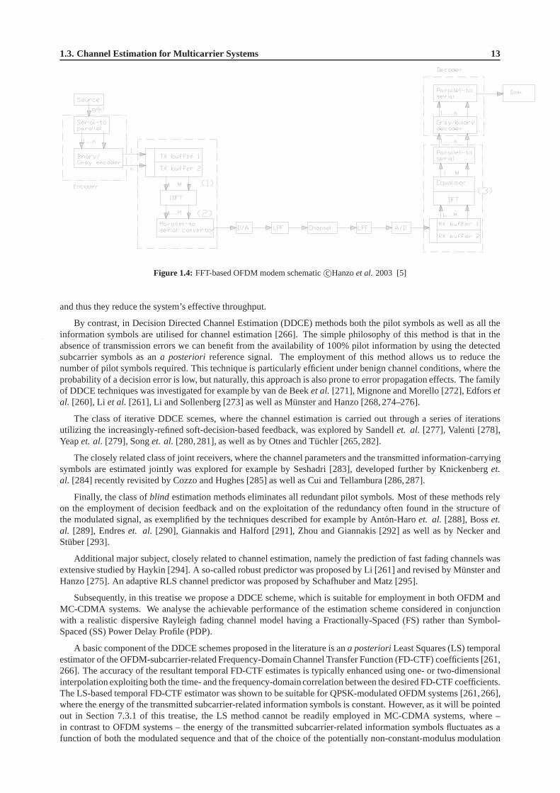
1.3. Channel Estimation for Multicarrier Systems 13
Figure 1.4: FFT-based OFDM modem schematicc©Hanzoet al. 2003 [5]
and thus they reduce the system’s effective throughput.
By contrast, in Decision Directed Channel Estimation (DDCE) methods both the pilot symbols as well as all theinformation symbols are utilised for channel estimation [266]. The simple philosophy of this method is that in theabsence of transmission errors we can benefit from the availability of 100% pilot information by using the detectedsubcarrier symbols as ana posteriori reference signal. The employment of this method allows us toreduce thenumber of pilot symbols required. This technique is particularly efficient under benign channel conditions, where theprobability of a decision error is low, but naturally, this approach is also prone to error propagation effects. The familyof DDCE techniques was investigated for example by van de Beek et al. [271], Mignone and Morello [272], Edforsetal. [260], Li et al. [261], Li and Sollenberg [273] as well as Munster and Hanzo [268,274–276].
The class of iterative DDCE scemes, where the channel estimation is carried out through a series of iterationsutilizing the increasingly-refined soft-decision-based feedback, was explored by Sandellet. al. [277], Valenti [278],Yeapet. al.[279], Songet. al.[280,281], as well as by Otnes and Tuchler [265,282].
The closely related class of joint receivers, where the channel parameters and the transmitted information-carryingsymbols are estimated jointly was explored for example by Seshadri [283], developed further by Knickenberget.al. [284] recently revisited by Cozzo and Hughes [285] as well asCui and Tellambura [286,287].
Finally, the class ofblind estimation methods eliminates all redundant pilot symbols. Most of these methods relyon the employment of decision feedback and on the exploitation of the redundancy often found in the structure ofthe modulated signal, as exemplified by the techniques described for example by Anton-Haroet. al. [288], Bosset.al. [289], Endreset. al. [290], Giannakis and Halford [291], Zhou and Giannakis [292] as well as by Necker andStuber [293].
Additional major subject, closely related to channel estimation, namely the prediction of fast fading channels wasextensive studied by Haykin [294]. A so-called robust predictor was proposed by Li [261] and revised by Munster andHanzo [275]. An adaptive RLS channel predictor was proposedby Schafhuber and Matz [295].
Subsequently, in this treatise we propose a DDCE scheme, which is suitable for employment in both OFDM andMC-CDMA systems. We analyse the achievable performance of the estimation scheme considered in conjunctionwith a realistic dispersive Rayleigh fading channel model having a Fractionally-Spaced (FS) rather than Symbol-Spaced (SS) Power Delay Profile (PDP).
A basic component of the DDCE schemes proposed in the literature is ana posterioriLeast Squares (LS) temporalestimator of the OFDM-subcarrier-related Frequency-Domain Channel Transfer Function (FD-CTF) coefficients [261,266]. The accuracy of the resultant temporal FD-CTF estimates is typically enhanced using one- or two-dimensionalinterpolation exploiting both the time- and the frequency-domaincorrelation between the desired FD-CTF coefficients.The LS-based temporal FD-CTF estimator was shown to be suitable for QPSK-modulated OFDM systems [261,266],where the energy of the transmitted subcarrier-related information symbols is constant. However, as it will be pointedout in Section 7.3.1 of this treatise, the LS method cannot bereadily employed in MC-CDMA systems, where –in contrast to OFDM systems – the energy of the transmitted subcarrier-related information symbols fluctuates as afunction of both the modulated sequence and that of the choice of the potentially non-constant-modulus modulation

14 Chapter1. Introduction to OFDM and MIMO-OFDM
Table 1.9: Major contributions addressing the problem of channel estimation in MIMO systems.
[296] Li et. al., 2002 MIMO-OFDM for wireless communications: signal detection with enhancedchannel estimation.
[297] Stuberet. al., 2004 An important overview encompassing most of the major aspects of the broad-band MIMO-OFDM wireless communications including channelestimation,signal detection as well as time and frequency syncronization.
[298] Denget. al., 2003 Decision directed iterative channel estimation for MIMO systems.
[285] Cozzo and Hughes, 2003 Joint channel estimation and data detection in space-time communications.
[299] Munster and Hanzo,2005 Parallel-interference-cancellation-assisted decision-directed channel estimationfor OFDM systems using multiple transmit antennas.
[300] Yatawatta and Petropulu, 2006 Blind channel estimation in MIMO-OFDM systems with multiuser interference.
scheme itself. Thus we propose a Minimum Mean Square Error (MMSE) estimation based DDCE method, which isan appropriate solution for employment in both OFDM and MC-CDMA systems.
The system model and the channel model considered are described in Section 1.7 of this treatise. The difficultyof employing the LS approach to the problem of estimating theOFDM-subcarrier-related FD-CTF coefficients isdescribed in Section 7.3.1. The alternative MMSE FD-CTF estimator circumventing the problem outlined in Section7.3.1 is analyzed in Section 7.3.2. Our discourse evolves further by proposing a MMSE CIR estimator exploiting thefrequency-domain correlation of the FD-CTF coefficients inSection 7.4.1 and a reduced-complexity version of theCTF MMSE estimator considered is proposed in Section 7.4.2.The computational complexity of both methods iscompared in Section 7.4.3.
In Section 7.4 we continue our discourse with the derivationof both sample-spaced as well as fractionally-spacedChannel Impulse Response (CIR) estimator. In Section 7.4.5we then perform a comparison between the two methodsconsidered and demonstrate the advantages of the later,i. e. fractionally-spaced scheme. Subsequently, in Section 7.5we develope a method of parametric tracking of the fractionally-spaced channel impulse response (CIR) taps, whichfacilitates low-complexity channel etimation in realistic channel conditions characterized by time-variant fractionally-spaced power delay profile. More specifically we employ the Projection Approximation Subspace Tracking (PAST)method for the sake of recursive tracking of the channel transfer function’s (CTF) covariance matrix and subsequenttracking of the corresponding CIR taps. We demonstrate thatthe PAST-aided decision directed channel estimationscheme proposed exhibits good performance over the entire range of practical conditions.
In Section 7.6 we discuss two major CIR tap prediction strategies. Specifically, In Section 7.6.2 the so-calledrobust implementation of the stationary Minimum Mean Square Error(MMSE) CIR predictor is considered. TherobustCIR predictor [261] assumes a constant-valued, limited-support channel scattering function [266] during thedesign of the CIR tap prediction filter and hence relies on theassumption of encountering the worst possible channelconditions. On the other hand, in Section 7.6.4 we discuss the adaptive Recursive Least Squares (RLS) method ofCIR prediction [295]. As opposed to the robust CIR predictorof [261], the RLS CIR predictor does not require anyexplicit information concerning the channel conditions encountered. Consequently, in Section 7.6.5 we characterizeand compare the achievable performance of both methods considered and draw conclusions concerning their relativemerits. Specifically, we demonstrate that the RLS prediction technique outperforms its robust counterpart over theentire range of the relevant channel conditions.
In Section 7.7 we characterize the achievable performance of the resultant PAST-aided DDCE scheme. We reportan estimation efficiency ofκ = −18dB exhibited by a system employing 10% of pilots and communicating overa dispersive Rayleigh fading channel having a Doppler frequency of fD = 0.003. Furthermore, we report a BERperformance, which is only 3 dB from the corresponding BER performance exhibited by a similar system assumingperfect channel knowledge.
1.4 Channel Estimation for MIMO-OFDM
In spite of an immense interest from both the academic and theindustrial communities, a practical multiple-inputmultiple-output (MIMO) transceiver architecture, capable of approaching channel capacity boundaries in realisticchannel conditions remains largely an open problem. In particular, a robust and accurate channel estimation in MIMOsystems constitutes a major issue, preventing us from achieving the high capacities predicted by the relevant theoreticalanalysis.

1.5. Signal Detection in MIMO-OFDM Systems 15
Some of the major contributions addressing the problem of channel estimation in MIMO systems are summarizedin Table 1.9. More specifically, a combined OFDM/SDMA approach was discussed by Vandenameeleet. al.[301]. Apilot-based approach to the problem of MIMO channel estimation has been explored by Jungnickelet. al. in [302],by Bolcskeiet. al. [303] as well as by Zhuet. al. [304]. On the other hand, decision directed iterative channelestimation for MIMO systems was addressed by Liet al [296, 305, 306] as well as Denget al [298]. Furthermore,parallel interference cancellation-assisted decision-directed channel estimation scheme for MIMO-OFDM systemswas proposed by Munster and Hanzo [299, 307]. Joint decoding and channel estimation for MIMO channels wasconsidered by Grant [308] and further investigated by Cozzoand Hughes [285]. Iterative channel estimation forspace-time block coded systems was addressed by Maiet al [309], while joint iterative DDCE for turbo coded MIMO-OFDM systems was investigated by Qiao [310]. Blind channel estimation in MIMO-OFDM systems with multiuserinterference was explored by Yatawatta and Petropulu [300].
Other closely related issues, namely the iterative tracking of the channel-related parameters using soft decisionfeedback was studied by Sandellet. al[277], while the iterative channel estimation in the context of turbo equalizationwas considered by Songet. al.[281], Mai et. al.[311], as well as Otnes and Tuchler [265].
Finally, an important overview publication encompassing most major aspects of broadband MIMO-OFDM wire-less communications including channel estimation and signal detection, as well as time and frequency syncronizationwas contributed by Stuberet. al.[297].
Agains this background, in this treatise we propose a decision-directed channel estimation (DDCE) scheme, whichis suitable for employment in a wide range of multi-antenna multi-carrier systems as well as over the entire rangeof practical channel conditions. In particular, we consider mobile wireless multipath channels, which exhibit fastRayleigh frequency-selective fading and are typically characterized by time-variant power delay profile (PDP).
We consider a generic MIMO-OFDM system employingK orthogonal frequency-domain subcarriers and havingmt andnr transmit and receive antennas, respectively. Consequently, our MIMO channel estimation scheme comprisesan array ofK per-subcarrier MIMO-CTF estimators, followed by a(nr × mt)-dimensional array of parametric CIRestimators and a corresponding array of(nr × mt × L) CIR tap predictors, whereL is the number of tracked CIR tapsper link for the MIMO channel.
In Section 7.8.1 we explore a family of recursive MIMO-CTF tracking methods, which in conjunction with theaforementioned PAST-aided CIR-tracking method of Section7.5 as well as the RLS CIR tap prediction method ofSection 7.6.4, facilitate an effective channel estimationscheme in the context of a MIMO-OFDM system. Morespecifically, in Section 7.8.1 we consider both hard- and soft-feedback assisted least mean squares (LMS) and recur-sive least squares (RLS) tracking algorithms as well as the modified RLS algorithm, which is capable of improvedutilization of the soft information associated with the decision-based estimates.
Finally, in Section 7.8.1.5 we document the achievable performance of resultant MIMO-DDCE scheme employingthe recursive CTF tracking followed by the parametric CIR tap tracking and CIR tap prediction. We demonstrate thatthe MIMO-DDCE scheme proposed exhibits good performance over the entire range of practical conditions.
Both the bit error rate (BER) as well as the corresponding mean square error (MSE) performance of the channelestimation scheme considered is characterized in the context of a turbo-coded MIMO-OFDM system. We demostratethat the MIMO-DDCE scheme proposed remains effective in channel conditions associated with high terminal speedsof up to 130 km/h, which corresponds to the OFDM-symbol normalized Doppler frequency of 0.006. Additionally,we report a virtually error-free performance of a rate1/2 turbo-coded 8x8-QPSK-OFDM system, exhibiting a totalbit rate of 8 bits/s/Hz and having a pilot overhead of only 10%, at SNR of 10dB and normalized Doppler frequency of0.003, which corresponds to the mobile terminal speed of roughly 65 km/h1.
1.5 Signal Detection in MIMO-OFDM Systems
The demand for both high data-rates, as well as for improved transmission integrity requires an efficient utilisationof the limited system resources, while supporting a high grade of mobility in diverse propagation environments.Consequently, the employment of an appropriate modulationformat, as well as an efficient exploitation of the availablebandwidth constitute crucial factors in achieving a high performance.
The OFDM modulation scheme employed in conjunction with a Multiple-Input Multiple-Output (MIMO) archi-tecture [266], where multiple antennas are employed at boththe transmitter and the receiver of the communicationsystem, constitutes an attractive solution in terms of satisfying these requirements. Firstly, the OFDM modulation
1Additional system parameters are characterized in Table 1.11.

16 Chapter1. Introduction to OFDM and MIMO-OFDM
technique is capable of coping with the highly frequency selective, time-variant channel characteristics associatedwith mobile wireless communication channels, while possessing a high grade of structural flexibility for exploitingthe beneficial properties of MIMO architectures.
It is highly beneficial that OFDM and MIMOs may be conveniently combined, since the information-theoreticalanalysis predicts [312] that substantial capacity gains are achievable in communication systems employing MIMOarchitectures. Specifically, if the fading processes corresponding to different transmit-receive antenna pairs may beassumed to be independently Rayleigh distributed2, the attainable capacity was shown to increase linearly with thesmaller of the numbers of the transmit and receive antennas [312]. Additionally, the employment of MIMO archi-tectures allows for the efficient exploitation of the spatial diversity available in wireless MIMO environments, thusimproving the system’s BER, as well as further increasing the system’s capacity.
The family of space-time signal processing methods, which allow for the efficient implementation of communi-cation systems employing MIMO architectures are commonly referred to in parlance assmart antennas. In recentyears, the concept of smart antennas has attracted intensive research interest in both the academic and the industrialcommunities. As a result, a multiplicity of smart antenna-related methods has been proposed. These include methodsimplemented at the transmitter, the receiver or both.
The classification of the smart-antenna techniques is illustrated in Figure 1.5. It should be noted, however, that theclassification presented here is somewhat informal and its sole purpose is to appropriately position the content of thistreatise in the context of the extensive material availableon the subject.
Figure 1.5: Classification of space-time processing techniques.
Two distinctive system scenarios employing smart antennascan be identified. The first is the so-called Space Devi-sion Multiplexing (SDM)-type scenario [313], where twopeerterminals each employing multiple antennas, commu-nicate with each other over a MIMO channel and the multiple antennas are primarily used for achieving a multiplexinggain,i.e. a higher throughput [314]. The second scenario correspondsto the Space Devision Multiple Access (SDMA)configuration [266], where a singlebase-station, employing multiple antennas communicates simultaneously using asingle carrier frequency with multipleuserterminals, each employing one or several antennas.
The variouspoint-to-multipointsmart antenna applications can be further subdivided intouplink- and down-link-related applications. Theuplink-related methods constitute a set of techniques, which can be employed in thebase stationin order to detect the signals simultaneously transmitted by multiple user terminals. More specifically,provided that the Channel Impulse Response (CIR) of all users is accurately estimated, it may be used as theirunique, user-specific spatial signature for differentiating them, despite communicating within the same frequency
2This assumption is typically regarded as valid, if the appropriate antenna spacing is larger than ofλ/2, whereλ is the corresponding wavelength.

1.5. Signal Detection in MIMO-OFDM Systems 17
band [266]. Hence, the corresponding space-time signal processing problem is commonly referred to as Multi-UserDetection (MUD) [266], while the multi-antenna multi-usersystems employinguplink space-time MUD are com-monly referred to as SDMA systems [266]. In contrast to the SDM-type systems designed for achieving the highestpossible multiplexing gain, the design objective of the SDMA techniques is the maximization of the number of userssupported. By contrast, the class of beamformers [315] creates angularly selective beams for both the up-link anddown-link in the direction of the desired user, while forming nulls towards the interfering users. Finally, the family ofSpace-Time Codes (STC) [316] was optimized for achieving the highest possible transmit diversity gain, rather thanfor multiplexing gain or for increasing the number of users supported. At the time of writing new research is aimingfor achieving both the maximum attainable diversity and multiplexing gain with the aid of eigen-value decomposi-tion [317].
As stated above, two benefits of employing smart antennas arethe system’s improved integrity, as well as theincreased aggregate throughput. Hence an adequate performance criterion of the particular smart antenna imple-mentation is a combination of the system’s attainable aggregate data-throughput, as well as the corresponding dataintegrity, which can be quantified in terms of the average BitError Rate (BER). Consequently, in the context of point-to-multipoint-related smart antenna applications the achievable capacity associated with the particular space-timeprocessing method considered may be assessed as a product ofthe simultaneously supported number of individualusers and the attainable data-rate associated with each supported user. The measure of data-integrity may be theaverage BER of all the users supported. Thus, the typical objective of the multi-user-related smart antenna implemen-tations, such as that of an SDMA scheme is that of increasing the number of the simultaneously supported users, whilesustaining the highest possible integrity of all the data communicated.
In this treatise, however, we would like to focus our attention on the family of space-time processing methodsassociated with thepoint-to-pointsystem scenario. The main objective of point-to-point space-time processing is toincrease the overall throughput of the system considered, as opposed to increasing the number of individual userssimultaneously supported by the system, which was the case in the multi-user SDMA scenario described above. Asillustrated in Figure 1.5, the family of time-space processing methods associated with thepoint-to-point-related smartantenna applications entail two different approaches, namely that of Space-Time Codes (STC) [316] as well as variouslayered space-time architectures, best known from Bell Labs Layered Space-Time (BLAST) scheme [314].
The STC methods may be classified in two major categories, namely the Space-Time Block Codes (STBC) and theSpace-Time Trellis Codes (STTC). A simple method of STBC wasfirst presented by Alamouti in [318]. Various STBCtechniques were then extensively studied in a series of major publications by Tarokhet al. in [319–325] as well as byAriyavistakulet al. in [326,327]. On the other hand, the original variant of BLAST, known as the Diagonal BLAST (D-BLAST) scheme, was first introduced by Foschini in [314]. A more generic version of the BLAST architecture,the so-called Vertical BLAST (V-BLAST) arrangement was proposed by Goldenet al. in [328]. Furthermore, thecomparative study of the D-BLAST, as well as the V-BLAST systems employing various detection techniques such asLeast Squares (LS) and Minimum Mean Square Error (MMSE)-aided Parallel Interference Cancellation (PIC), as wellas the LS- and MMSE-aided Successive Interference Cancellation (SIC) was carried out by Sweatmanet al. in [329].Typically, however, the term BLAST refers to the point-to-point single-carrier MIMO architecture employing the SICdetection method, as it was originally proposed in [314].
For the sake of accuracy, in this work we employ the alternative terminology of Space Division Multiplex-ing (SDM) in order to refer to a generic MIMO architecture. The corresponding detection methods are referred toas SDM Detection (SDMD) techniques, as opposed to the MUD techniques employed in the context of SDMA sys-tems [266]. Naturally, however, the SDMD and MUD schemes share the same signal detection methods, regardless,whether the signal arrived from multiple antennas of the same or different users. The classification of the most popularSDMD/MUD schemes is depicted in Figure 1.6. The methods considered include the linear LS and MMSE techniques,as well as non-linear techniques, such as Maximum Likelihood (ML), Successive Interference Cancellation (SIC), Ge-netic Algorithm-aided MMSE (GA-MMSE) [330, 331] as well as the novel Optimized Hierarchy Reduced SearchAlgorithm (OHRSA)-aided methods proposed in this treatise.
In the course of this treatise both the MIMO channel model considered as well as the SDM-OFDM system modelare described in Section 1.8. The various SDM detection methods considered are outlined in Chapter 15. Specifically,in Section 15.2.1 we demonstrate that the linear increase incapacity, predicted by the information-theoretic analy-sis [267], may indeed be achieved by employing a relatively low-complexity linear SDM detection method, such asthe MMSE SDM detection technique [332]. Secondly, in Section 15.3.1 we show that a substantially better perfor-mance can be achieved by employing a non-linear Maximum Likelihood (ML) SDM detector [313, 333, 334], whichconstitutes the optimal detection method from a probabilistic sequence-estimation point of view. To elaborate a littlefurther, the ML SDM detector is capable of attaining transmit diversity in fully-loadedsystems, where the numberof transmit and receive antennas is equal. Moreover, as opposed to the linear detection schemes considered, the MLSDM detector is capable of operating in therank-deficientsystem configuration, when the number of transmit anten-

18 Chapter1. Introduction to OFDM and MIMO-OFDM
Figure 1.6: SDM detection methods classification.
Table 1.10:Major Contributions Addressing the Sphere Decoder-Aided Space-Time Processing.
[335] Finckeet. al., 1985 Sphere decoder technique introduced.
[336] Damenet. al., 2000 Sphere decoder was first proposed for employment in the context of space-timeprocessing, where it is utilized for computing the ML estimates of the modu-lated symbols transmitted simultaneously from multiple transmit antennas.
[337] Hochwald and Brink, 2003 Thecomplexversion of the sphere decoder.
[338] Damenet. al., 2003 Further results on SD.
[339] Phamet al., 2004 Improved version of the complex sphere decoder.
[340] Tellamburaet al., 2005 Multistage sphere decoding was introduced.
nas exceeds that of the receive antennas. Unfortunately, however, the excessive computational complexity associatedwith the exhaustive search employed by the ML detection method renders it inapplicable to practical implementationin systems having a large number of transmit antennas. Subsequently, in Sections 15.3.2 and 15.3.3 we explore a rangeof advanced non-linear SDM detection methods, namely the SIC and Genetic Algorithm-aided MMSE detection, re-spectively, where the latter may potentially constitute anattractive compromise between the low complexity of thelinear SDM detection and the high performance of the ML SDM detection schemes. Indeed, we will demonstrate inSection 15.3.3 that the SDM detection method based on the SICas well as on the GA-MMSE detector [331] are bothcapable of satisfying these requirements.
In Section 15.4 our discourse evolves further by proposing an enhancement of the SDMD schemes considered byemploying both Space-Frequency Interleaving (SFI) and Space-Frequency Walsh-Hadamard Transform (SFWHT)-aided spreading. The performance benefits of employing SFI and SFWHT are quantified in Section 15.4. Finally, ourconclusions are summarized in Section 15.6.
Parallel-interference-cancellation-assisted decision-directed channel estimation for OFDM systems using multipletransmit antennas by Munster and Hanzo [299]
Recently, a family of potent Reduced Search Algorithm (RSA)aided Space-Time processing methods has beenexplored. These new methods utilize the Sphere Decoder (SD)technique introduced by Finckeet al. [335]. The SDwas first proposed for employment in the context of space-time processing by Damenet. al. in [336], where it isutilized for computing the ML estimates of the modulated symbols transmitted simultaneously from multiple transmitantennas. Thecomplexversion of the sphere decoder was proposed by Hochwald and Brink in [337]. The subjectwas further investigated by Damenet al. in [338]. Subsequently, an improved version of the Complex Sphere De-coder (CSD) was advocated by Phamet al. in [339]. Furthermore, CSD-aided detection was consideredby Cui andTellambura in a joint channel estimation and data detectionscheme explored in [286], while a revised version of theCSD method, namely the so-called Multistage Sphere Decoding (MSD) was introduced in [340]. The generalizedversion of the sphere decoder, which is suitable for employment in rank-deficient MIMO systems supporting more

1.6. Iterative Signal Processing for SDM-OFDM 19
transmitters than the number of receive antennas was introduced by Damenet al. in [341] and further refined by Cuiand Tellambura in [342]. The so-calledfastgeneralized sphere decoding was introduced by Yanget al. [343]. Yet an-other variant of sphere decoder algorithms with improved radius search was introduced by Zhao and Giannakis [344].The subject of approaching MIMO channel capacity using softdetection on hard sphere decoding was explored byWang and Giannakis [345]. Iterative detection and decodingin MIMO systems using sphere decoding was consideredby Vikalo et al. [346].
Consequently, a set of novel OHRSA-aided SDM detection methods are outlined in Section 16.1. Specifically, inSection 16.1.1 we derive the OHRSA-aided ML SDM detector, which benefits from the optimal performance of theML SDM detector [266], while exhibiting a relatively low computational complexity, which is only slightly higherthan that required by the low-complexity MMSE SDM detector [266]. To elaborate a little further, in Section 16.1.2we derive a bit-wise OHRSA-aided ML SDM detector, which allows us to apply the OHRSA method of Section 16.1in high-throughput systems, which employ multi-level modulation schemes, such asM-QAM [266].
In Section 16.1.3 our discourse evolves further by deducingthe OHRSA-aided Max-Log-MAP SDM detector,which allows for an efficient evaluation of the soft-bit information and therefore results in highly efficient turbo de-coding. Unfortunately however, in comparison to the OHRSA-aided ML SDM detector of Section 16.1.2 the OHRSA-aided Max-Log-MAP SDM detector of Section 16.1.3 exhibits asubstantially higher complexity. Consequently, inSection 16.1.5 we derive an approximate Max-Log-MAP method, which we refer to as Soft-output OPtimized HI-Erarchy (SOPHIE) SDM detector. The SOPHIE SDM detector combines the advantages of both the OHRSA-aidedML and OHRSA-aided Max-Log-MAP SDM detectors of Sections 16.1.2 and 16.1.3, respectively. Specifically, itexhibits a similar performance to that of the optimal Max-Log-MAP detector, while imposing a modest complexity,which is only slightly higher than that required by the low-complexity MMSE SDM detector [266]. The computationalcomplexity as well as the achievable performance of the SOPHIE SDM detector of Section 16.1.5 are analysed andquantified in Sections 16.1.5.1 and 16.1.5.2, respectively.
Our conclusions are summarized in Section??. Specifically, we report achieving a BER of10−4 at SNRs ofγ = 4.2, 9.2 and14.5 in high-throughput 8x8 rate-1
2 turbo-codedM = 4, 16 and64-QAM systems communicatingover dispersive Rayleigh fading channel. Additionally, wereport achieving a BER of10−4 at SNRs ofγ = 9.5, 16.3and22.8 in high-throughput rank-deficient 4x4, 6x4 and 8x4 rate-1
2 turbo-coded 16-QAM systems, respectively.
1.6 Iterative Signal Processing for SDM-OFDM
Figure 1.7: Schematic of a joint iterative receiver comprising channelestimator, SDM detector, as well as turbo decoderemploying two RCS serially-concatenated component codes.
In spite of an immense interest from both the academic and theindustrial communities, a practical multiple-inputmultiple-output (MIMO) transceiver architecture, capable of approaching channel capacity boundaries in realisticchannel conditions remains largely an open problem. An important overview publication encompassing most majoraspects of broadband MIMO-OFDM wireless communications including channel estimation and signal detection,as well as time and frequency syncronization was contributed by Stuberet al. [297]. Other important publicationsconsidering MIMO systems in realistic conditions include those by Munster and Hanzo [299], Liet. al. [296], Maiet. al. as well as Qiaoet. al. [310]. Nevertheless, substantial contributions addressing all the major issues inherent toMIMO transceivers, namely error correction, space-time detection as well as channel estimation in realistic channelconditions remain scarce.

20 Chapter1. Introduction to OFDM and MIMO-OFDM
Against this background, in Chapter 17.1 we derive an iterative, so calledturbomulti-antenna-multi-carrier (MAMC)receiver architecture. Our turbo receiver is illustrated in Figure 1.7. Following the philosophy of turbo process-ing [316], our turbo SDM-OFDM receiver comprises a succession of detection modules, which iteratively exchangesoft bit-related information and thus facilitate a substantial improvement of the overall system performance.
More specifically, our turbo SDM-OFDM receiver comprises three major components, namely, the soft-feedbackdecision-directed channel estimator, discussed in detailin Section 7.8, followed by the soft-input-soft-output OHRSALog-MAP SDM detector derived in Section 16.1.3 as well as a soft-input-soft-output serially concatenated turbocode [347]. Consequently, in this chapter we would like to analyze the achievable performance of each individualconstituent of our turbo receiver, as well as the achievableperformance of the entire iterative system. Our aim is toidentify the optimum system configuration, while considering various design trade-offs, such as achievable error-rateperformance, achievable data-rate as well as associated computational complexity.
In Section 17.4.2.4 we demonstrate that our turbo SDM-OFDM system employing the MIMO-DDCE scheme ofSection 7.8 as well as the OHRSA Log-MAP SDM detector of Section 16.1.3 remains effective in channel conditionsassociated with high terminal speeds of up to 130 km/h, whichcorresponds to the OFDM-symbol normalized Dopplerfrequency of 0.006. Additionally, we report a virtually error-free performance for a rate1/2 turbo-coded 8x8-QPSK-OFDM system, exhibiting an effective throughput of 8 MHz· 8 bits/s/Hz=64 Mbps and having a pilot overhead ofonly 10% at SNR of 7.5dB and a normalized Doppler frequency of0.003, which corresponds to a mobile terminalspeed of about 65 km/h.
1.7 System Model
1.7.1 Channel Statistics
Figure 1.8: Illustration of a wireless multi-path communication link.Note that the non-line of sight paths are randomlyfaded as a result of the diffraction induced by scattering surfaces.
A Single Input Single Output (SISO) wireless communicationlink is constituted by a multiplicity of statisticallyindependent components, termed aspaths. Thus, such a channel is referred to as amultipathchannel. Amultipathchannel is typically characterized by its Power Delay Profile (PDP), which is a set of parameters constituted by thepaths’ average powersσ2
l and the corresponding relative delaysτl. Some examples of the commonly used PDPs areillustrated in Figure 1.10. The physical interpretation ofeach individual path is a single distortionless ray betweenthe transmitter and the receiver antennas. While the term PDP corresponds to the average power values associatedwith the different multi-path channel components, the termCIR refers to the instantaneous state of the dispersivechannel encountered and corresponds to the vector of the instantaneous amplitudesαl [n] associated with differentmulti-path components. Thus, the statistical distribution of the CIR is determined by the channel’s PDP. In the caseof independently Rayleigh fading multiple paths we haveαl [n] ∈ CN (0, σ2
l ), l = 1, 2, · · · , L, whereCN (0, σ2) is acomplex-Gaussian distribution having the mean0 and the variance ofσ2.
The individual scattered and delayed signal components usually arise as a result of refraction or diffraction fromscattering surfaces, as illustrated in Figure 1.8, and are termed as Non-Line-Of-Sight (NLOS) paths. In most recentlyproposed wireless mobile channel models each such CIR componentαl associated with an individual channel pathis modelled by a Wide Sense Stationary (WSS) narrow-band complex Gaussian process [350] having correlationproperties characterised by the cross-correlation function
rα[m, j] = Eαi[n]α∗j [n − m] = rt;i[m]δ[i − j] , (1.1)
1.7.1. Channel Statistics 21
Figure 1.9: Illustration of a wireless multi-path communication link.Note that the non-line of sight paths are randomlyfaded as a result of the diffraction induced by scattering surfaces.
wheren is a discrete OFDM-block-related time-domain index andδ[·] is the Kronecker delta function. The aboveequation suggests that the different CIR components are assumed to be mutually uncorrelated and each exhibits time-domain autocorrelation properties defined by the time-domain correlation functionrt;i[m]. The Fourier transformpair of the correlation functionrt[n] associated with each CIR tap corresponds to a band-limited Power SpectralDensity (PSD)pt( f ), such that we havept( f ) = 0, if | f | > fD, whereFd is termed as themaximum Dopplerfrequency. The time period1/ fD is the so-calledcoherence timeof the channel [350] and usually we have:1/ fD ≫ T,whereT is the duration of the OFDM block.
A particularly popular model of the time-domain correlation functionrt[n] was proposed by Jakes in [351] and isdescribed by
rt[n] = rJ [n] = J0(nwd), (1.2)
whereJ0(x) is a zero-order Bessel function of the first kind andwd = 2πT fD is the normalised Doppler frequency.The corresponding U-shaped PSD function, termed as the Jakes-spectrum is given by [351]
p J(w) =
2wd
1√1−(w/wd)
2, if |w| < wd
0, otherwise.
Generally speaking the Doppler frequenciesfD can assume different values for different signal paths. However, asit was advocated in [261], for the sake of exploiting the time-domain correlation in the context of channel parametersestimation and prediction, it is sufficient to make a worst-case assumption about the nature of time-domain correlationof the channel parameters encountered. The associated worst-case channel time-domain correlation properties can becharacterized by an ideally band-limited Doppler PSD function given by [261,266]
pt( f ) = pB,uni f ( f ) =
12 fD
, if | f | < fD
0, otherwise,(1.3)
where fD is the assumed value of the maximum Doppler frequency over all channel paths. The corresponding time-

22 Chapter1. Introduction to OFDM and MIMO-OFDM
(a) (b) (c)
Figure 1.10: Power Delay Profiles (PDP) corresponding to three differentchannel models, namely (a) the Short WirelessAsynchronous Transfer Mode (SWATM) channel model of [266],(b) Bug’s channel model [348] and (c) the COST-207Bad Urban (BU) channel model defined for UMTS-type system, ascharacterized in [349].
domain correlation function can be described as
rt[m] = rB[m] =sin 2π fDm
2π fDm. (1.4)
(a) (b)
Figure 1.11: (a) Frequency response and (b) impulse response of an order 8raised cosine shaping filter with theoversampling rate of 4, the roll-off factor of 0.2 and the delay of 3 samples.
We adopt the complex baseband representation of the continuous-time Channel Impulse Response (CIR), as givenby [350]
h(t, τ) = ∑l
αl(t)c(τ − τl), (1.5)
whereαl(t) is the time-variant complex amplitude of thelth path and theτl is the corresponding path delay, whilec(τ) is the aggregate impulse response of the transmitter-receiver pair, which usually corresponds to the raised-cosineNyquist filter. From (1.5) the continuous Channel Transfer Function (CTF) can be described as in [306]
H(t, f ) =∫ ∞
−∞h(t, τ) e−2π f τdτ
= C( f ) ∑l
αl(t)e−2π f τl, (1.6)
whereC( f ) is the Fourier transform pair of the transceiver impulse responsec(τ) characterized in Figure 1.11.
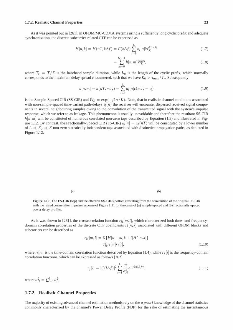
1.7.2. Realistic Channel Properties 23
As it was pointed out in [261], in OFDM/MC-CDMA systems usinga sufficiently long cyclic prefix and adequatesynchronisation, the discrete subcarrier-related CTF canbe expressed as
H[n, k] = H(nT, k∆ f ) = C(k∆ f )L
∑l=1
αl [n]Wkτl /Ts
K (1.7)
=K0−1
∑m=0
h[n, m]WkmK , (1.8)
whereTs = T/K is the baseband sample duration, whileK0 is the length of the cyclic prefix, which normallycorresponds to the maximum delay spread encountered, such that we haveK0 > τmax/Ts. Subsequently
h[n, m] = h(nT, mTs) =L
∑l=1
αl [n]c(mTs − τl) (1.9)
is the Sample-Spaced CIR (SS-CIR) andWK = exp(−2π/K). Note, that in realistic channel conditions associatedwith non-sample-spaced time-variant path-delaysτl(n) the receiver will encounter dispersed received signal compo-nents in several neighbouring samples owing to the convolution of the transmitted signal with the system’s impulseresponse, which we refer to as leakage. This phenomenon is usually unavoidable and therefore the resultant SS-CIRh[n, m] will be constituted of numerous correlated non-zero taps described by Equation (1.5) and illustrated in Fig-ure 1.12. By contrast, the Fractionally-Spaced CIR (FS-CIR) αl [n] = αl(nT) will be constituted by a lower numberof L ≪ K0 ≪ K non-zero statistically independent taps associated with distinctive propagation paths, as depicted inFigure 1.12.
(a) (b)
Figure 1.12: TheFS-CIR (top) and the effectiveSS-CIR(bottom) resulting from the convolution of the original FS-CIRwith the raised cosine filter impulse response of Figure 1.11for the cases of (a) sample-spaced and (b) fractionally-spacedpower delay profiles.
As it was shown in [261], the crosscorrelation functionrH [m, l], which characterized both time- and frequency-domain correlation properties of the discrete CTF coefficients H[n, k] associated with different OFDM blocks andsubcarriers can be described as
rH [m, l] = E H[n + m, k + l]H∗[n, k]= σ2
Hrt[m]r f [l], (1.10)
wherert[m] is the time-domain correlation function described by Equation (1.4), whiler f [i] is the frequency-domaincorrelation functions, which can be expressed as follows [262]
r f [l] = |C(l∆ f )|2L
∑i=1
σ2i
σ2H
e−2πl∆ f τi, (1.11)
whereσ2H = ∑
Li=1 σ2
i .
1.7.2 Realistic Channel Properties
The majority of existing advanced channel estimation methods rely on thea priori knowledge of the channel statisticscommonly characterized by the channel’s Power Delay Profile(PDP) for the sake of estimating the instantaneous

24 Chapter1. Introduction to OFDM and MIMO-OFDM
Channel Impulse Response (CIR) and the corresponding Channel Transfer Function (CTF). It is evident however, thatin realistic wireless mobile channels, where at least one ofthe communicating terminals is in motion, the channel’sPDP will also become time-variant and thus may not bea priori known at the receiver.
For the sake of designing as we as characterizing the performance of an efficient and robust channel estimationscheme, which will be suitable for realistic channel conditions, we propose a channel model, which sustains theimportant characteristics of the realistic wireless mobile channels. More specifically, as opposed to the conventionalconstant PDP, our channel model is characterized by a time-variant PDP, where both the relative delaysτl as well asthe corresponding average powersσ2
l of different PDP taps vary with time.
Our channel model is dynamically generated using a geometric scattering model illustrated in Figure 1.13. Morespecifically, the individual scatterers associated with different propagation paths are randomly generated using a Mar-cov statistical model. The corresponding relative delaysτl and powersσ2
l associated with each propagation path arecalculated based on the geometrical location of each of the scatterers. Correspondingly, the rate of change in thevalues of the PDP tap delaysτl is determined by the speed of the mobile wireless terminal and is characterized by thePDPtap drift rateparameterντ. The specific assumptions regarding the practical range of values of the parameterντ
is discussed in the next chapter. Furthermore, each propagation path experiences independent fast Rayleigh fading.Finally, the set of parameters characterizing the Marcov model employed is chosen such that the average channelstatistics corresponds to the desired static-PDP channel model.
Figure 1.13: PDP examples corresponding.
1.7.3 Baseline Scenario Characteristics
As a baseline scenario we consider a mobile wireless communication system utilizing a frequency bandwidth ofB = 10 MHz at a carrier frequency offc = 2.5 GHz. Furthermore, we assume an OFDM system havingK = 128orthogonal subcarriers. The corresponding FFT-frame duration is Ts = K/B = 16 µs. We assume having a cyclicprefix of1/4Ts = 4 µs and thus the total OFDM symbol duration ofT = 20 µs.
Some other important system-related assumptions include the relative speed of the communicating terminals,which we assume not to exceedv = 130 km/h = 36 m/s. Furthermore, the OFDM-symbol-normalized Doppler

1.7.4. MC Transceiver 25
frequencyfD relates to the relative speed of the communicating terminals as follows
fD = Tv fc
c, (1.12)
wherec = 3 · 108 m/s denotes the speed of light. The actual Doppler frequencyfD/T encountered in the mobilewireless environment is assumed to be in the range of 3 to 300 Hz, where the maximum value of300 Hz correponds tothe relative terminal speed ofv = 130 km/h and the carrier frequency offc = 2.5 GHz. Finally, the OFDM-symbol-normalized PDP tap drift speedντ may be calculated as follows
ντ = Tv
c, (1.13)
which suggests the that value of the PDP tap drift speed parameter does not exceed the maximum value ofντ =2.4 · 10−6 µs = T · 0.12 µs/s.
Table 1.11:Baseline scenario system characteristics.
Parameter Value
Carrier frequencyfc 2.5 GHzChannel bandwidthB 8 MHzNumber of carriersK 128FFT frame durationTs 16 µsOFDM symbol durationT 20 µs (4 µs of cyclic prefix)Max. delay spreadτmax 4 µsMax. terminal speedv 130 km/hNorm. Max. Doppler spreadfD 0.006 = T · 300 HzNorm. Max. PDP tap driftντ 2.4 · 10−6 µs = T · 0.12 µs/s
The resultant baseline scenario system characteristics are summarized in Table 1.11
1.7.4 MC Transceiver
Figure 1.14: Schematic illustration of a typical OFDM/MC-CDMA system’sPHY layer.
The transmitter part of the system is typically constitutedof an OFDM / MC-CDMA Encoder and Modulator, theoutput of which is a complex-valued base-band time-domain signal. The resultant base-band signal is oversampled andpulse-shaped using a Nyquist filter, such as, for example, a root-raised-cosine filter characterized in Figure 1.11. The

26 Chapter1. Introduction to OFDM and MIMO-OFDM
resultant oversampled signal is then converted into an analog pass-band signal using a D/A converter and upconvertedto the Radio Frequency (RF) band. At the receiver side a reciprocal process is taking place, where the received RFsignal is amplified by the RF frontend and downconverted to anintermediate frequency pass-band, then sampled bythe A/D converter, downconverted to the base-band, filteredby a matched Nyquist filter and finally decimated. Theresultant complex-valued base-band signal is processed bythe corresponding OFDM / MC-CDMA Demodulator andDecoder block, where the transmitted information symbols are detected.
In this treatise we consider the link between the output of the MC Modulator and the input of the MC Demodulatorof Figure 1.14 as anEffective Base-Band Channel. The proof of feasibility for this assumption is beyond the scopethis contribution, however it can be found for example in [350,352].
The discrete frequency-domainmodel of the OFDM/MC-CDMA system illustrated in Figure 1.14 can be describedas in [306]
y[n, k] = H[n, k]x[n, k] + w[n, k], (1.14)
for k = 0, . . . , K − 1 and alln, wherey[n, k], x[n, k] andw[n, k] are the received symbol, the transmitted symbol andthe Gaussian noise sample respectively, corresponding to the kth subcarrier of thenth OFDM block. Furthermore,H[n, k] represents the complex-valued CTF coefficient associated with the kth subcarrier and time instancen. Notethat in the case of anM-QAM modulated OFDM system,x[n, k] corresponds to theM-QAM symbol accommodatedby thekth subcarrier, while in a MC-CDMA system, such as a Walsh-Hadamard Transform (WHT) assisted OFDMscheme usingG-chip WH spreading code and hence capable of supportingG users [266] we have
x[n, k] =G−1
∑p=0
c[k, p]s[n, p], (1.15)
wherec[k, p] is thekth chip of thepth spreading code, whiles[n, p] is theM-QAM symbol spread by thepth code.Each of theG spreading codes is constituted byG chips.
1.8 SDM-OFDM System Model
1.8.1 MIMO Channel Model
We consider a MIMO wireless communication system employingmt transmit andnr receive antennas, hence, thecorresponding MIMO wireless communication channel is constituted by(nr × mt) propagation links, as illustratedin Figure 1.15. Furthermore, each of the corresponding(nr × mt) Single Input Single Output (SISO) propagationlinks comprises a multiplicity of statistically independent components, termed aspaths. Thus, each of these SISOpropagation links can be characterised as amultipathSISO channel discussed in detail in Section 1.7.1. Similarlyto the SISO case, the multi-carrier structure of our SDM-OFDM transceiver allows us to characterise the broadbandfrequency-selective channel considered as an OFDM subcarrier-related vector of flat-fading Channel Transfer Func-tion (CTF) coefficients. However, as opposed to the SISO case, for each OFDM symboln and subcarrierk the MIMOchannel is characterized by a(nr × mt)-dimensional matrixH[n, k] of the CTF coefficients associated with the differ-ent propagation links, such that the elementHij[n, k] of the CTF matrixH[n, k] corresponds to the propagation linkconnecting thejth transmit andith receive antennas.
Furthermore, the correlation properties of the MIMO-OFDM channel can be readily derived as a generalisation ofthe SISO-OFDM channel scenario discussed in detail in Section 1.7.1. As it was shown in [261], the crosscorrelationfunctionrH [m, l], which characterizes both the time- and frequency-domain correlation properties of the discrete CTFcoefficientsHij[n, k] associated with the particular(i, j)th propagation link of the MIMO channel, as well as with thedifferent OFDM symbol and subcarrier indicesn andk can be described as
rH;ij[m, l] = E
H∗ij[n + m, k + l], Hij[n, k]
= σ2Hrt[m]r f [l], (1.16)
wherert[m] is the time-domain correlation function, which may be characterized by a time-domain correlation modelproposed by Jakes in [351], where we have
rt[m] = rJ [m] = J0(nwd), (1.17)

1.8.2. Channel Capacity 27
Figure 1.15: Illustration of a MIMO channel constituted bymt transmit andnr receive antennas. The correspondingMIMO channel is characterized by the(nr × mt)-dimensional matrixH of CTF coefficients.
and J0(x) is a zero-order Bessel function of the first kind, whilewd = 2πT fD is the normalised Doppler frequency.On the other hand, the frequency-domain correlation functionr f [l] can be expressed as follows [262]
r f [l] = |C(l∆ f )|2L
∑i=1
σ2i
σ2H
e−2πl∆ f τi, (1.18)
whereC( f ) is the frequency response of the pulse-shaping filter employed by the particular system,σ2i andτi, i =
1, · · · , L are the average power and the corresponding delay of theL-tap Power Delay Profile (PDP) encountered,while σ2
H is the average power per MIMO channel link, such that we haveσ2H = ∑
Li=1 σ2
i .
In this report we assume the different MIMO channel links to be mutually uncorrelated. This common assump-tion is usually valid, if the spacing between the adjacent antenna elements exceedsλ/2, whereλ is the wavelengthcorresponding to the RF signal employed. Thus, the overall crosscorrelation function between the(i, j)th and(i′, j′)thpropagation links may be described as
rH;ij;i′ j′ [m, l] = E
H∗i′ j′ [n + m, k + l], Hij[n, k]
= σ2Hrt[m]r f [l]δ[i − i′]δ[j − j′], (1.19)
whereδ[i] is the discrete Kronecker Delta function.
1.8.2 Channel Capacity
Whilst most of the multi-path NLOS channel models can be collectively categorized as Rayleigh fading, differentchannel models characterized by different PDPs exhibit substantial differences in terms of theirinformation-carryingcapacityandpotential diversity gain. The channel’s capacity determines the upper-bound for theoverall system’sthroughput. On the other hand, the available diversity gainallows the communication system to increase its trans-mission integrity. Various modulation and coding schemes can be employed by the communication system in orderto increase its spectral efficiency and also to take advantage of diversity. Some of these methods are widely dis-cussed in the literature,e.g. in [353], and include the employment of antenna arrays, space-time coding, time- andfrequency-domain spreading, channel coding, time- and frequency-domain repetitionetc. The theoretical performanceboundaries of such methods are discussed in [267, 354]. Furthermore, the trade-offs between the attainable systemcapacity gain and the corresponding diversity gain are addressed in [355].
Consequently, the unrestricted capacity of a generic single-carrier ergodic-flat-fading MIMO channel can be ex-pressed as in [337], where we have
C = E
log det
[
σ2wI +
1
mtHHH
]
, (1.20)
whereH is a(nr × mt)-dimensional matrix with independent complex Gaussian distributed entries.

28 Chapter1. Introduction to OFDM and MIMO-OFDM
(a) (b)
Figure 1.16: CapacityC of Equation (1.20) as well as mutual informationI(s; y) of Equation (1.21) versus SNR for (a)1x1 and (2) 2x2 systems in Rayleigh uncorrelated flat fading.
In realistic communication system, however, the achievable throughput is limited by the modulation scheme em-ployed. Some examples of such modulation schemes areMary PSK orMary QAM constellation schemes, whereM isthe number of complex symbols constituting the constellation map corresponding to the particular modulation schemeemployed. The upper bound defining the maximum throughput achievable by a particular discrete modulation schemewas first discussed by Shannon in [356] and was shown to be determined by the mutual informationI(s; y) exhibitedby the modulation scheme employed. The mutual information can be calculated using the following expression
I(s; y) = H(y)− H(y|s), (1.21)
whereH(·) = −E log p(·) denotes the entropy function [356]. In the case of having a Gaussian i.i.d. noise samplevectorw with the corresponding covariance matrix given byCw = σ2
wI, the constrained entropy constituentH(y|s)of Equation (1.21) is may be expressed as follows [337]
H(y|x) = nr log 2πσ2we, (1.22)
whereas the unconstrained entropy constituentH(y) can be approximated numerically using a Monte-Carlo simulationas in [337], where we have
H(y) = −E log
(
1
Mmt(2πσ2w)nr
∑s
exp
[
− 1
2σ2w‖y − Hs‖2
]
)
, (1.23)
where the expectation is taken over the three sources of randomness in the choice ofs, H and w. Moreover, thesummation in Equation (1.23) is carried out over allMmt possible values ofs.
Figures 1.16(a) and 1.16(b) characterize both the capacityC of Equation (1.20) as well as the mutual informationI(s; y) of Equation (1.21) for SISO and 2x2-MIMO systems, respectively. The mutual information plots depicted inboth figures correspond to systems employing QPSK as well as 16- and 64-QAM modulations.
1.8.3 SDM-OFDM Transceiver Structure
The schematic of a typical SDM-OFDM system’s physical layeris depicted in Figure 1.17. The transmitter of theSDM-OFDM system considered is typically constituted by theEncoder and Modulator seen in Figure 1.17, generatinga set ofmt complex-valued base-band time-domain signals [266]. The modulated base-band signals are then processedin parallel. Specifically, they are oversampled and shaped using a Nyquist filter, such as for example a root-raised-cosine filter. The resultant oversampled signals are then converted into an analog pass-band signal using a bank of D/Aconverters and upconverted to the Radio Frequency (RF) band. At the receiver side of the SDM-OFDM transceiver theinverse process takes place, where the set of received RF signals associated with thenr receive antenna elements areamplified by the RF amplifier and down-converted to an intermediate frequency pass-band. The resultant pass-bandsignals are then sampled by a bank of A/D converters, down-converted to the base-band, filtered by a matched Nyquistfilter and finally decimated, in order to produce a set of discrete complex-valued base-band signals. The resultant set

1.8.3. SDM-OFDM Transceiver Structure 29
Figure 1.17: Schematic of a typical SDM-OFDM system’s physical layer.
of discrete signals is processed by the corresponding Demodulator and Decoder module seen in Figure 1.17, wherethe transmitted information-carrying symbols are detected.
In this treatise we consider the link between the output of the SDM-OFDM Modulator and the input of the cor-responding SDM-OFDM Demodulator of Figure 1.17 as anEffective Base-Band MIMO Channel. The proof of fea-sibility for this assumption is beyond the scope this contribution, however it can be found for example in [350, 352].The structure of the resultant base-band SDM-OFDM system isdepicted in Figure 1.18, where the bold grey arrowsillustrate subcarrier-related signals represented by thevectorsxi andyi, while the black thin arrows accommodatescalar time-domain signals.
Figure 1.18: Schematic of a generic SDM-OFDM BLAST-type transceiver.
The discrete frequency-domain model of the SDM-OFDM system, illustrated in Figure 1.18, may be characterised

30 Chapter1. Introduction to OFDM and MIMO-OFDM
as a generalisation of the SISO case described in of Section 1.7.1. Namely, we have
yi[n, k] =mt
∑j=1
Hij[n, k]xj[n, k] + wi[n, k], (1.24)
wheren = 0, 1, · · · andk = 0, . . . , K−1 are the OFDM symbol and subcarrier indices, respectively, while yi[n, k], xj[n, k]andwi[n, k] denote the symbol received at theith receive antenna, the symbol transmitted from thejth transmit antennaand the Gaussian noise sample encountered at theith receive antenna, respectively. Furthermore,Hij[n, k] representsthe complex-valued CTF coefficient associated with the propagation link connecting thejth transmit andith receiveantennas at thekth OFDM subcarrier and time instancen. Note that in the case of anM-QAM modulated OFDMsystem,xj[n, k] corresponds to theM-QAM symbol accommodated by thekth subcarrier of thenth OFDM symboltransmitted from thejth transmit antenna element.
The SDM-OFDM system model described by Equation (1.24) can be interpreted as the per OFDM-subcarriervector expression of
y[n, k] = H[n, k]x[n, k] + w[n, k], (1.25)
where we introduce the space-devision-related vectorsy[n, k], x[n, k] andw[n, k], as well as a space-devision-related(nr × mt)-dimensional matrix of CTF coefficientsH[n, k]. Note that similarly to the SISO case, the multi-carrierstructure of the SDM-OFDM transceiver allows us to represent the broadband frequency-selective MIMO channel asa subcarrier-related vector of flat-fading MIMO-CTF matricesH[n, k].
1.9 Novel Aspects and Outline of the Book
Having briefly reviewed the OFDM, MIMO-OFDM and SDMA-OFDM literature, let us now outline the organizationof the monograph.
• Chapter 3: Channel Coding Assisted STBC-OFDM SystemsAs an introductory study, in this chapter we discuss variouschannel coded Space-Time Block Codes (STBCs) inthe context of single-user single-carrier and single-userOFDM systems. This work constitutes the backgroundwork for the multi-user systems to be investigated in following chapters. More specifically, various TurboConvolutional (TC) codes, Low Density Parity Check (LDPC) codes and Coded Modulation (CM) schemes arecombined with STBCs for improving the performance of the single-user system considered.
• Chapter 4: Coded Modulation Assisted Multi-User SDMA-OFDM Using Frequency-Domain SpreadingIn this chapter, we invoke a multi-user MIMO SDMA-OFDM system for uplink communications, where theclassic Minimum Mean-Square Error (MMSE) Multi-User Detector (MUD) is employed at the BS for separatingthe different users’ signals. The CM schemes discussed in Chapter 3, namely Trellis Coded Modulation (TCM),Turbo TCM (TTCM), Bit-Interleaved Coded Modulation (BICM)and Iteratively Decoded BICM (BICM-ID),are evaluated and compared in the context of the SDMA-OFDM system. Furthermore, the performance gainarising from invoking Walsh-Hadamard Transform Spreading(WHTS) across a block of OFDM subcarriers inthe Frequency Domain (FD) is studied in both the uncoded SDMA-OFDM and the CM-assisted SDMA-OFDMsystems.
• Chapter 5: Hybrid Multi-User Detection for SDMA-OFDM Syste msThis chapter focuses on the design of MUDs invoked by the SDMAreceiver. Specifically, the Maximum Likeli-hood Detection (MLD) scheme is found to attain the best performance at the cost of a computational complexitythat increases exponentially both with the number of users and with the number of Bits Per Symbol (BPS) trans-mitted by higher-order modulation schemes. By contrast, the MMSE MUD exhibits a lower complexity at theexpense of a performance loss. In order to achieve a good performance-complexity tradeoff, Genetic Algorithm(GA) based MUD techniques are proposed for employment in channel coded SDMA-OFDM systems, whereTTCM is used. Moreover, a novel BiasedQ-function Based Mutation (BQM) assisted iterative GA (IGA)MUDis designed. The performance of the proposed BQM-IGA is compared to both that of the optimum MLD andthe linear MMSE MUD in the so-called fully-loaded and overloaded scenarios, respectively, where the numberof users is equal to or higher than the number of receiver antenna elements. Additionally, the computationalcomplexity associated with the various MUD schemes is discussed.
• Chapter 6: Direct-Sequence Spreading and Slow Subcarrier-Hopping Aided Multi-User SDMA-OFDMSystems

1.9. Novel Aspects and Outline of the Book 31
This chapter commences with a short review of conventional SDMA-OFDM systems, followed by an intro-duction to hybrid SDMA-OFDM arrangements, which incorporate Direct-Sequence Spreading (DSS) and/orFrequency-Hopping (FH) techniques into conventional SDMA-OFDM. A novel FH technique referred to asSlow SubCarrier-Hopping (SSCH) is designed for hybrid DSS/FH SDMA-OFDM systems using a TTCMscheme. Furthermore, two types of SSCH pattern are discussed, namely the Random SSCH (RSSCH) andthe Uniform SSCH (USSCH) patterns. The performance of the proposed TTCM-assisted DSS/SSCH SDMA-OFDM system is evaluated and compared to the conventional SDMA-OFDM and various hybrid SDMA-OFDMconfigurations.
• Chapter 7: Channel Estimation for OFDM and MC-CDMAWe derive an advanced decision directed channel estimation(DDCE) scheme, which is capable of recursivetracking and prediction of the rapidly-fluctuating channelparameters, characterized by time-variant statistics.More specifically, we employ a Projection Approximation Subspace Tracking (PAST) [357] technique for thesake of tracking the channel transfer function’s low-rank signal subspace and thus facilitating a high accuracytracking of the channel’s transfer function, while imposing a relatively low computational complexity.
• Chapter 8: Iterative Joint Channel Estimation and Multi-Us er Detection for SDMA-OFDM SystemsThe objective of this chapter is to develop an efficient solution to the channel estimation problem of multi-userMIMO-OFDM systems. It is well-known that compared to Single-Input Single-Output (SISO) systems, channelestimation in the MIMO scenario becomes more challenging, owing to the increased number of independenttransmitter-receiver links to be estimated. Against this background, an iterative, joint channel estimation andsymbol detection approach is proposed for LDPC-coded MIMO SDMA-OFDM systems. More specifically,the method modifies the GA MUD advocated in Chapter 5 so that itbecomes capable of jointly optimizing theFrequency-Domain CHannel Transfer Functions (FD-CHTFs) and the multi-user data symbols. Moreover, anefficient algorithm is derived, which enables the GA to output soft bits for the sake of improving the performanceof the LDPC channel decoder.
• Chapter 9: Reduced-Complexity Sphere Detection for Uncoded SDMA-OFDM SystemsThe main objective of this chapter is to systematically review the fundamentals of the SD, which is consideredto be one of the most proming low-complexity near-optimum detection technique at the time of writing. Fur-thermore, we address the SD-related complexity reduction issues. Specifically, the principle of the Hard-InputHard-Output (HIHO) SD is reviewed first in the context of boththe depth-first and breadth-first tree searchbased scenarios, along with that of the GSD, which is applicable to challenging rank-deficient MIMO scenar-ios. A comprehensive comparative study of the complexity reduction schemes devised for different types ofSDs, namely, the conventional depth-first SD, theK-best SD and the novel OHRSA detector, is carried out byanalyzing their conceptual similarities and differences.Finally, their achievable performance and th complexityimposed by the various types of SDs are investigated in comparison to each other.
• Chapter 10: Reduced-Complexity Iterative Sphere Detection for Channel Coded SDMA-OFDM SystemsThe fundamentals of the LSD scheme are studied at the beginning of this chapter in the context of an iterativedetection aided channel coded MIMO-OFDM system. A potentially excessive complexity may be imposed bythe conventional LSD, since it has to generate soft information for every transmitted bit, which requires the ob-servation of a high number of hypotheses about the transmitted MIMO symbol. Based on the above-mentionedcomplexity issue, we contrive a generic center-shifting SDscheme and the so-calledapriori-LLR-thresholdassisted SD scheme with the aid of EXIT chart analysis, both of which are capable of effectively reducingthe potentially high complexity imposed by the SD-aided iterative receiver. Moreover, we combine the above-mentioned schemes in the interest of further reducing the complexity imposed. In addition, for the sake ofenhancing the achievable iterative detetion gains and hence improving the bandwidth efficiency, a Unity-RateCode (URC) assisted three-stage serially concatenated transceiver employing the so-called Irregular Convo-lutional Codes (IrCCs) is devised. Finally, the benefits of the proposed center-shifting SD scheme are alsoinvestigated in the context of the above-mentioned three-stage iterative receiver.
• Chapter 11: Sphere Packing Modulated STBC-OFDM and its Sphere DetectionIn this chapter we extend the employment of the turbo-detected Sphere Packing (SP) aided Space-Time BlockCoding (STBC) scheme to Multi-User MIMO (MU-MIMO) scenarios, because SP was demonstrated to becapable of providing useful performance improvements overconventionally-modulatedorthogonal design basedSTBC schemes in the context of Single-User MIMO (SU-MIMO) systems. For the sake of achieving a near-MAP performance, while imposing a moderate complexity, we specifically design theK-best SD scheme forsupporting the operation of the SP-modulated system, sincethe conventional SD cannot be directly applied tosuch a system. Consequently, when relying on our SD, a significant performance gain can be achieved by theSP-modulated system over its conventionally-modulated counterpart in the context of MU-MIMO systems.
32 Chapter1. Introduction to OFDM and MIMO-OFDM
• Chapter 12: Multiple-Symbol Differential Sphere Detection for Cooperative OFDMThe principle of the MSDSD is first reviewed, which has been recently proposed for mitigating the time-selective-channel-induced performance loss suffered by classic direct transmission schemes employing the Con-ventional Differential Detection (CDD) scheme. Then, we specifically design the MSDSD for both the Differ-ential Amplify-and-Forward (DAF) and Differential Decode-and-Forward (DDF) assisted cooperative systemsbased on the multi-dimensional tree search proposed in Chapter 4, which is capable of achieving a significantperformance gain for transmission over time-selective channels induced by the relative mobility amongst thecooperating transceivers.
• Chapter 13: Resource Allocation for the Differentially Modulated Cooperative UplinkIn this chapter the theoretical BER performance of both the DAF- and DDF-aided cooperative cellular up-links are investigated. Then, based on the minimum BER criterion, we design efficient Cooperating-User-Selection (CUS) and Adaptive-Power-Allocation (APA) schemes for the above-mentioned two types of differ-entially modulated cooperative systems, while requiring no Channel State Information (CSI) at the receiver.Moreover, we investigate the Cooperative-Protocol-Selection (CPS) of the uplink system in conjunction witha beneficial CUS as well as the APA scheme in order to further improve the achievable end-to-end perfor-mance, leading to a resource-optimized hybrid cooperativesystem. Hence, a number of cooperating MSs maybe adaptively selected from the available MS candidate pooland the cooperative protocol employed by a specificcooperating MS may also be adaptively selected in the interest of achieving the best possible BER performance.
• Chapter 14: The Near-Capacity Differentially Modulated Cooperative Cellular Uplink The DDF-aidedcooperative system’s DCMC capacity is investigated in comparison to that of its classic direct-transmissionbased counterpart in order to answer the grave fundamental question, whether it is worth introducing cooperativemechanisms into the development of wireless networks, suchas the cellular voice and data networks. Then, wepropose a practical framework of designing a cooperative system, which is capable of performing close to thenetwork’s corresponding non-coherent DCMC capacity. Based on our low-complexity near-capacity designcriterion, a novel Irregular Distributed Hybrid Concatenated Differential (Ir-DHCD) coding scheme is contrivedfor the DDF cooperative system employing our proposed capacity-achieving low-complexity adaptive-window-aided SISO iterative MSDSD scheme.
• Chapter 15: Multi-Stream Detection for SDM-OFDM SystemsThe multi-stream detection problem of SDM-OFDM systems is similar to the MUD techniques of SDMA-OFDM arrangements, which are classified and reviewed in thischapter.
• Chapter 16: Approximate Log-MAP SDM DetectionWe propose the novel family of Optimized Hierarchy Reduced Search Algorithm (OHRSA)-aided space-timeprocessing methods, which may be regarded as an advanced extension of the Complex Sphere Decoder (CSD)method, portrayed in [339]. The algorithm proposed extendsthe potential application range of the CSD methodsof [337] and [339], as well as reduces the associated computational complexity. Moreover, the OHRSA-aidedSDM detector proposed exhibits the near-optimum performance of the Log-MAP SDM detector, while imposinga substantially lower computational complexity, which renders it an attractive design alternative for practicalsystems.
• Chapter 17: Iterative Channel Estimation and Detection forSDM-OFDMFinally, we propose an iterative turbo receiver architecture, which utilises both the soft decision feedback aidedMIMO channel estimation scheme of Chapter 7 as well as the Log-MAP SDM detection method derived inChapter 16. Additionally, we carry out an analysis of the associated design trade-offs.
• Chapter 18: Conclusions and Future WorkThe major findings of our work are summarized in this chapter,including our suggestions for future research.
1.10 Chapter Summary
The historic development of various MIMO techniques was briefly summarized in Section 1.1.1.1, followed by arudimentary introduction to MIMO-OFDM systems in Section 1.1.1.2. In Section 1.1.1.3 a concise review of variousSDMA and SDMA-OFDM techniques was given, highlighting the associated signal processing problems.

Chapter2OFDM Standards
During the past decades, wireless communication has benefitted from substantial advances and it is considered as thekey enabling technique of innovative future consumer products. For the sake of satisfying the requirements of variousapplications, significant technological achievements arerequired to ensure that wireless devices have appropriatearchitectures suitable for supporting a wide range of services delivered to the users.
In the foreseeable future, the large-scale employment of wireless devices and the requirements of high-bandwidthapplications are expected to lead to tremendous new challenges in terms of the efficient exploitation of the achievablespectral resources. New wireless techniques, such as UltraWideBand (UWB) [358], advanced source and channelencoding as well as various smart antenna techniques, for example Space-Time Codes (STCs) [359], Space Divi-sion Multiple Access (SDMA) [5] and beamforming, as well as other Multiple-Input Multiple-Output (MIMO) [93]wireless architectures are capable of offering substantial improvements over classic communication systems. Henceresearchers have focused their attention on the next generation of wireless broadband communications systems, whichaim for delivering multimedia services requiring data rates much higher than existing ones. Undoubtedly, supportingsuch high data rates, while maintaining a high robustness against radio channel impairments, such as multi-path fadingand frequency-selective fading, requires further enhanced system architectures.
The organisation of this chapter is as follows. In Sections 2.1, 2.2 and 2.3, we review various major internationalstandards that adopt OFDM, namely Wi-Fi, the Third-Generation Partnership Project (3GPP) Long-Term Evolution(LTE) and Worldwide Interoperability for Microwave Access(WiMAX) standards, respectively. Finally, we concludethe chapter in Section 2.4.
2.1 Wi-Fi
In 1999, the Wi-Fi Alliance was founded as a global, non-profit organization, aiming for developing a single globallyaccepted standard for high-speed WLANs. The mission of the Wi-Fi Alliance was to promote the Wi-Fi technologyand the corresponding Wi-Fi product certification. The Wi-Fi Alliance has now more than 300 members from morethan 20 countries and Wi-Fi has achieved a huge worldwide success. A study [360] released in September 2008 bythe Wi-Fi Alliance found that an increased number of consumers in the United States, the United Kingdom and Japanvalue the Wi-Fi Certified brand. Developed in March 2000, thecertification program has approved more than 4,800products from various vendors worldwide.
2.1.1 IEEE 802.11 Standards
Wi-Fi is based on the IEEE 802.11 standard family. The first version of IEEE 802.11 was released in 1997 [361],which was rectified in 1999 [362]. Then, two further supplements of 802.11-1999 were released, the first one beingIEEE 802.11a [363], which provides a bit rate of up to 54 Mbps in the 5 GHz band. In comparison to 802.11-1999,where Frequency-Hopping Spread Spectrum (FHSS) or Direct-Sequence Spread Spectrum (DSSS) are used, 802.11aemploys an OFDM scheme, which applies to Wireless Asynchronous Transfer Mode (WATM) networks and accesshubs. The second supplement to 802.11-1999 was IEEE 802.11b[364], which has a maximum data rate of 11 Mbpsin the 2.4 GHz band and uses the same media access method as that defined in 802.11-1999.

34 Chapter2. OFDM Standards
Further enhancements to 802.11 were made later. The IEEE 802.11d-2001 standard [365] introduced the supportof international roaming services. The IEEE 802.11g-2003 standard [366], which exploits the same OFDM modula-tion scheme as 802.11a, provides a data rate of 20-54 Mbps in the 2.4 GHz band. Other improvements include IEEE802.11h [367], IEEE 802.11i [368] and IEEE 802.11j [369], which introduced spectrum and transmit power manage-ment in the 5 GHz band in Europe, security enhancements, and operation in the 4.9-5 GHz band in Japan, respectively.In November 2005, the release of IEEE 802.11e-2005 [370] provided further QoS enhancements.
As the number of standards in the 802.11 family grew up, it wasproposed by the working group that a singledocument combining all up-to-date 802.11 specifications should be provided. This resulted in the IEEE 802.11-2007standard [371], a new release that includes all previous 802.11 amendments. In 2008, another two amendments werecompleted. The IEEE 802.11k-2008 [372] extends 802.11 by specifying mechanisms for Radio Resource Measure-ment (RRM), and the IEEE 802.11r-2008 [373] provides mechanisms for fast Basic Service Set (BSS) transition.
Some of the 802.11 standards are still in the drafting stage,such as the IEEE 802.11n standard [57], which aimsfor developing next-generation WLANs by incorporating MIMO-OFDM techniques. It is expected to offer high-throughput wireless transmission at 100-200Mbps. The IEEE802.11y standard [374] will provide support for theoperation in the 3650-3700 MHz band in U.S.A.
As a brief summary, we highlight the major 802.11 standards in Tables 2.1, 2.2 and 2.3.
Year Standard Title
1997 802.11-1997 [361] IEEE Standard for Information Technology - Telecommunications and Information Ex-
change Between Systems - Local and Metropolitan Area Networks - Specific Require-
ments - Part 11: Wireless LAN Medium Access Control (MAC) andPhysical Layer
(PHY) Specifications
1999 802.11-1999 [362] IEEE Standard for Information Technology - Telecommunications and Information Ex-
change Between Systems - Local and Metropolitan Area Networks - Specific Require-
ments - Part 11: Wireless LAN Medium Access Control (MAC) andPhysical Layer
(PHY) Specifications
802.11a-1999 [363] Supplement to IEEE Standard for Information Technology - Telecommunications and
Information Exchange Between Systems - Local and Metropolitan Area Networks -
Specific Requirements - Part 11: Wireless LAN Medium Access Control (MAC) and
Physical Layer (PHY) Specifications: High-speed Physical Layer in the 5 GHz Band
802.11b-1999 [364] Supplement to IEEE Standard for Information Technology - Telecommunications and
Information Exchange Between Systems - Local and Metropolitan Area Networks -
Specific Requirements - Part 11: Wireless LAN Medium Access Control (MAC) and
Physical Layer (PHY) Specifications: Higher-speed Physical Layer Extension in the 2.4
GHz Band
2001 802.11d-2001 [365] IEEE Standard for Information Technology - Telecommunications and Information Ex-
change Between Systems - Local and Metropolitan Area Networks - Specific Require-
ment - Part 11: Wireless LAN Medium Access Control (MAC) and Physical Layer
(PHY) Specification - Amendment 3: Specifications for Operation in Additional Regu-
latory Domains
Table 2.1: The family of the IEEE 802.11 Standards (1997-2001).

2.2. 3GPP Long-Term Evolution 35
Year Standard Title
2003 802.11g-2003 [366] IEEE Standard for Information Technology - Telecommunications and Information Ex-
change Between Systems - Local and Metropolitan Area Networks - Specific Require-
ments - Part 11: Wireless LAN Medium Access Control (MAC) andPhysical Layer
(PHY) Specifications - Amendment 4: Further Higher Data RateExtension in the 2.4
GHz Band
802.11h-2003 [367] IEEE Standard for Information Technology - Telecommunications and Information Ex-
change Between Systems - Local and Metropolitan Area Networks - Specific Require-
ments - Part 11: Wireless LAN Medium Access Control (MAC) andPhysical Layer
(PHY) Specifications - Amendment 5: Spectrum and Transmit Power Management Ex-
tensions in the 5 GHz band in Europe
2004 802.11i-2004 [368] IEEE Standard for Information Technology - Telecommunications and Information Ex-
change Between Systems - Local and Metropolitan Area Networks - Specific Require-
ments - Part 11: Wireless LAN Medium Access Control (MAC) andPhysical Layer
(PHY) Specifications - Amendment 6: Medium Access Control (MAC) Security En-
hancements
802.11j-2004 [369] IEEE Standard for Information Technology - Telecommunications and Information Ex-
change Between Systems - Local and Metropolitan Area Networks - Specific Require-
ments - Part 11: Wireless LAN Medium Access Control (MAC) andPhysical Layer
(PHY) Specifications - Amendment 7: 4.9 GHz-5 GHz Operation in Japan
2005 802.11e-2005 [370] IEEE Standard for Information Technology - Telecommunications and Information Ex-
change Between Systems - Local and Metropolitan Area Networks - Specific Require-
ments - Part 11: Wireless LAN Medium Access Control (MAC) andPhysical Layer
(PHY) Specifications - Amendment 8: Medium Access Control (MAC) Quality of Ser-
vice Enhancements
Table 2.2: The family of the IEEE 802.11 Standards (2003-2005).
2.2 3GPP Long-Term Evolution
The Third-Generation Partnership Project (3GPP) is an international standardisation body working on the specificationof the 3G Universal Terrestrial Radio Access Network (UTRAN) and on the Global System for Mobile communica-tions (GSM). The latest specification that is being studied and developed in 3GPP is an evolved 3G radio access,widely known as the Long-Term Evolution (LTE) or Evolved UTRAN (E-UTRAN), as well as an evolved packetaccess core network in the System Architecture Evolution (SAE). The initial requirements for LTE were set out inearly 2005, which are briefly summarised in Table 2.4 and in [375].
The initial objective of 3GPP was to produce global specifications for a 3G mobile system evolving from theexisting GSM core network. This includes the Wideband CDMA (WCDMA) based UTRA Frequency Division Duplex(FDD) mode and the Time Division Code Division Multiple Access (TD-CDMA) based UTRA Time Division Duplex(TDD) mode [377]. In December 2005, it was decided that the LTE radio access should be based on OFDMA in thedownlink (DL) and Single-Carrier Frequency Division Multiple Access (SC-FDMA) in the uplink (UL). SC-FDMA isalso known as Discrete Fourier Transform Spread OFDMA (DFTS-OFDMA). The main PHY parameters of the LTEDL are summarised in Table 2.5.
Briefly, the objective of the SAE is to migrate circuit-switched networks towards packet-switched networks. Thisis set out in the recent 3GPP releases, where an Evolved Packet Core was defined. The main targets of SAE can bedivided into the following aspects [377]:

36 Chapter2. OFDM Standards
Year Standard Title
2007 802.11-2007 [371] IEEE Standard for Information Technology - Telecommunications and Information Ex-
change Between Systems - Local and Metropolitan Area Networks - Specific Require-
ments - Part 11: Wireless LAN Medium Access Control (MAC) andPhysical Layer
(PHY) Specifications
2008 802.11k-2008 [372] IEEE Standard for Information Technology - Telecommunications and Information Ex-
change Between Systems - Local and Metropolitan Area Networks - Specific Require-
ments - Part 11: Wireless LAN Medium Access Control (MAC) andPhysical Layer
(PHY) Specifications - Amendment 1: Radio Resource Measurement of Wireless LANs
(Amendment to IEEE 802.11-2007)
802.11r-2008 [373] IEEE Standard for Information Technology - Telecommunications and Information
Exchange Between Systems - Local and Metropolitan Area Networks - Specific Re-
quirements - Part 11: Wireless LAN Medium Access Control (MAC) and Physical
Layer (PHY) Specifications - Amendment 2: Fast Basic ServiceSet (BSS) Transition
(Amendment to IEEE 802.11-2007 and IEEE 802.11k-2008)
P802.11n-2008 [57] Draft IEEE Standard for Information Technology - Telecommunications and Informa-
tion Exchange Between Systems - Local and Metropolitan AreaNetworks - Specific
Requirements - Part 11: Wireless LAN Medium Access Control (MAC) and Physical
Layer (PHY) Specifications - Amendment 4: Enhancements for Higher Throughput
P802.11y-2008 [374] Draft IEEE Standard for Information Technology - Telecommunications and Informa-
tion Exchange Between Systems - Local and Metropolitan AreaNetworks - Specific
Requirements - Part 11: Wireless LAN Medium Access Control (MAC) and Physical
Layer (PHY) Specifications - Amendment 3: 3650-3700 MHz Operation in USA (Draft
Amendment to IEEE 802.11-2007)
Table 2.3: The family of the IEEE 802.11 Standards (2007-2008).
• high-level user and operational aspects,
• basic capabilities,
• multi-access and seamless mobility,
• man-machine interface aspects,
• performance requirements for the evolved 3GPP,
• security as well as privacy, and
• charging aspects of the system.
2.3 WiMAX Evolution
The rapidly growing demand for flexible, high-speed broadband services requires advanced communication technolo-gies. The more conventional family of high-rate broadband access techniques has relied on wired access, such asDigital Subscriber Line (DSL), cable modems, ethernet and optical fibers. However, the extension of the coveragearea results in a significantly increased cost imposed by building and maintaining wired networks. This is particularlytrue for less densely populated zones, for example suburbanand rural areas.
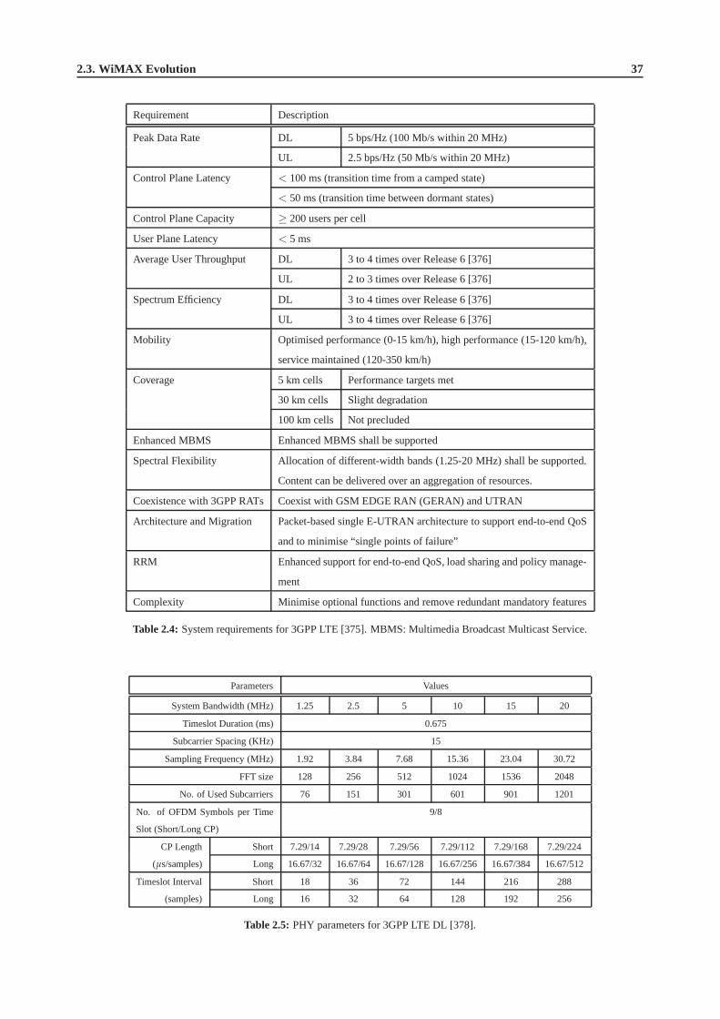
2.3. WiMAX Evolution 37
Requirement Description
Peak Data Rate DL 5 bps/Hz (100 Mb/s within 20 MHz)
UL 2.5 bps/Hz (50 Mb/s within 20 MHz)
Control Plane Latency < 100 ms (transition time from a camped state)
< 50 ms (transition time between dormant states)
Control Plane Capacity ≥ 200 users per cell
User Plane Latency < 5 ms
Average User Throughput DL 3 to 4 times over Release 6 [376]
UL 2 to 3 times over Release 6 [376]
Spectrum Efficiency DL 3 to 4 times over Release 6 [376]
UL 3 to 4 times over Release 6 [376]
Mobility Optimised performance (0-15 km/h), high performance (15-120 km/h),
service maintained (120-350 km/h)
Coverage 5 km cells Performance targets met
30 km cells Slight degradation
100 km cells Not precluded
Enhanced MBMS Enhanced MBMS shall be supported
Spectral Flexibility Allocation of different-width bands (1.25-20 MHz) shall besupported.
Content can be delivered over an aggregation of resources.
Coexistence with 3GPP RATs Coexist with GSM EDGE RAN (GERAN) and UTRAN
Architecture and Migration Packet-based single E-UTRAN architecture to support end-to-end QoS
and to minimise “single points of failure”
RRM Enhanced support for end-to-end QoS, load sharing and policy manage-
ment
Complexity Minimise optional functions and remove redundant mandatory features
Table 2.4: System requirements for 3GPP LTE [375]. MBMS: Multimedia Broadcast Multicast Service.
Parameters Values
System Bandwidth (MHz) 1.25 2.5 5 10 15 20
Timeslot Duration (ms) 0.675
Subcarrier Spacing (KHz) 15
Sampling Frequency (MHz) 1.92 3.84 7.68 15.36 23.04 30.72
FFT size 128 256 512 1024 1536 2048
No. of Used Subcarriers 76 151 301 601 901 1201
No. of OFDM Symbols per Time
Slot (Short/Long CP)
9/8
CP Length Short 7.29/14 7.29/28 7.29/56 7.29/112 7.29/168 7.29/224
(µs/samples) Long 16.67/32 16.67/64 16.67/128 16.67/256 16.67/384 16.67/512
Timeslot Interval Short 18 36 72 144 216 288
(samples) Long 16 32 64 128 192 256
Table 2.5: PHY parameters for 3GPP LTE DL [378].

38 Chapter2. OFDM Standards
Hence, Broadband Wireless Access (BWA) techniques have emerged as potent competitors of their conventionalwired counterparts, facilitating the provision of broadband services for subscribers that are far from the coveragearea of the wired networks. Being flexible, efficient and cost-effective, BWA provides an excellent solution to over-come the above-mentioned coverage problem. During the pastdecade or so, a number of proprietary wireless accesssystems have been developed by the wireless industry. Naturally, these proprietary products were based on diversespecifications, which inevitably limited their applications and markets. As a matter of fact, the potential benefits ofBWA services were not expected to be widely achieved due to the lack of a common international standard, until theemergence of the Worldwide Interoperability for MicrowaveAccess (WiMAX) standard [379].
WiMAX is one of the most popular BWA technologies available at the time of writing, aiming to provide high-speed broadband wireless access for Wireless MetropolitanArea Networks (WMANs) [380]. As a standardised tech-nology, WiMAX ensures the inter-operability of equipment certified by the WiMAX Forum, resulting in a significantcost reduction for service providers that would like to use products manufactured by diverse vendors. This dis-tinct advantage has paved the way for global broadband wireless services. Another key benefit of WiMAX is thatit has been optimised for offering excellent Non-Line-of-Sight (NLOS) coverage with the aid of advanced wirelesstransmission techniques, such as Multiple-Input Multiple-Output (MIMO) transmit/receive diversity and AutomaticRe-transmission Request (ARQ), etc [381], combined with Orthogonal Frequency Division Multiplexing (OFDM) orOrthogonal Frequency Division Multiple Access (OFDMA) [381].
This section is organised as follows. In Section 2.3.1, we first briefly outline the historic background of WiMAX.Specifically, the IEEE 802.16 standard family is reviewed inSection 2.3.1.1, which has tight links to WiMAX, fol-lowed by the introduction of the WiMAX Forum in Section 2.3.1.3. Then a brief introduction of the Korean WiMAXstandard, Wireless Broadband (WiBro), is provided in Section 2.3.1.4. In Section 2.3.2, we proceed with discussing thetechnical aspects of WiMAX, including WiMAX-I in Section 2.3.2.1 and WiMAX-II in Section 2.3.2.2, respectively.The trends concerning the future of WiMAX are summarised in Section 2.3.3.
2.3.1 Historic Background
In this section, we will commence by briefly reviewing the IEEE 802.16 standard family in Section 2.3.1.1, and portraythe brief history of the WiMAX Forum in Section 2.3.1.3. The connection between WiMAX and WiBro is establishedin Section 2.3.1.4.
2.3.1.1 IEEE 802.16 Standard Family
WiMAX is closely related to the IEEE 802.16 standard family.Before elaborating on WiMAX, let us first brieflyreview the history of the IEEE 802.16 Standards outlined in Table 2.6.
The IEEE 802.16 Working Group (WG) was chartered to define theair interface for BWA systems in certainlicensed frequency bands. The 802.16 specifications conform to the family of IEEE 802 standards, governing the LocalArea Networks (LANs) and Metropolitan Area Networks (MANs)endorsed by the IEEE in 1990 [391]. As opposedto the IEEE 802.11 WG, which focuses on Wireless Local Area Network (WLAN) standards and applications, theIEEE 802.16 WG has been focused on developing cost-efficientpoint-to-multipoint BWA architectures that enablemultimedia broadband services in MANs and Wide Area Networks (WANs) [391].
2.3.1.2 Early 802.16 Standards
As early as in 1998, the IEEE 802.16 group was formed to develop a radio standard for wireless broadband communi-cations. In December 2001, the first member of the IEEE 802.16standard family was approved, widely referred to asIEEE 802.16-2001 [382]. It focuses on a Line-of-Sight (LOS)based point-to-multipoint wireless broadband systemoperating in the 10-66 GHz band. It utilises a Single-Carrier (SC) based physical layer (PHY) in conjunction with aburst Time Division Multiplexed (TDM) Media Access Control(MAC) layer [379].
Following the initial release of 802.16-2001, there had been two amendments, namely IEEE 802.16c-2002 [383]in December 2002, which provides detailed system profiles for the 10-66 GHz band, and IEEE 802.16a-2003 [384] inApril 2003, which presents some MAC modifications and additional PHY specifications for the 2-11 GHz band. Notethat in the standards rectified after 802.16a-2003, in addition to the SC-based PHY, both the OFDM and OFDMAbased PHY specifications are also included.

2.3.1. Historic Background 39
Year Standard Title
2001 802.16-2001 [382] IEEE Standard for Local and Metropolitan Area Networks - Part 16: Air Interface for
Fixed Broadband Wireless Access Systems
2002 802.16c-2002 [383] IEEE Standard for Local and Metropolitan Area Networks - Part 16: Air Interface for
Fixed Broadband Wireless Access Systems - Amendment 1: Detailed System Profiles
for 10-66 GHz
2003 802.16a-2003 [384] IEEE Standard for Local and Metropolitan Area Networks - Part 16: Air Interface for
Fixed Broadband Wireless Access Systems - Amendment 2: Medium Access Control
Modifications and Additional Physical Layer Specificationsfor 2-11 GHz
2004 802.16d-2004 [56] IEEE Standard for Local and Metropolitan Area Networks - Part 16: Air Interface for
Fixed Broadband Wireless Access Systems
2005 802.16e-2005 [385] IEEE Standard for Local and Metropolitan Area Networks - Part 16: Air Interface for
Fixed and Mobile Broadband Wireless Access Systems - Amendment 2: Physical and
Medium Access Control Layers for Combined Fixed and Mobile Operation in Licensed
Bands and Corrigendum 1
802.16f-2005 [386] IEEE Standard for Local and Metropolitan Area Networks - Part 16: Air Interface for
Fixed Broadband Wireless Access Systems - Amendment 1: Management Information
Base
2007 802.16k-2007 [387] IEEE Standard for Local and Metropolitan Area Networks Media Access Control
(MAC) Bridges - Amendment 5: Bridging of IEEE 802.16
802.16g-2007 [388] IEEE Standard for Local and Metropolitan Area Networks - Part 16: Air Interface for
Fixed and Mobile Broadband Wireless Access Systems - Amendment 3: Management
Plane Procedure and Services
2008 P802.16h [389] Draft IEEE Standard for Local and Metropolitan Area Networks - Part 16: Air Inter-
face for Fixed and Mobile Broadband Wireless Access Systems: Improved Coexistence
Mechanisms for License-Exempt Operation
P802.16j [390] Draft IEEE Standard for Local and Metropolitan Area Networks - Part 16: Air Interface
for Fixed and Mobile Broadband Wireless Access Systems Multihop Relay Specifica-
tion
Table 2.6: The family of the IEEE 802.16 Standards.

40 Chapter2. OFDM Standards
2.3.1.2.1 802.16d-2004 - Fixed WiMAX
The IEEE 802.16 standards developed during the early stagestend to describe different parts of the technology. Inorder to ease future developments, it was decided to merge the previous individual versions into a single one, resultingin IEEE 802.16d-2004 [56], which is also frequently referred to as IEEE 802.16-2004. For operational frequenciesspanning from 10-66 GHz, the PHY is based on SC modulation. For NLOS propagation conditions at frequenciesbelow 11 GHz, the design alternatives of SC, OFDM, or OFDMA modulation can be used [56].
Early WiMAX solutions were based on the Wireless Metropolitan Area Network (WirelessMAN) OFDM PHYof 802.16-2004. Therefore, 802.16-2004 is also known as “fixed WiMAX”, due to the fact that it does not supportmobility.
2.3.1.2.2 802.16e-2005 - Mobile WiMAX
In order to provide mobility support, the IEEE 802.16 working group continued their developments. In December2005, an amendment of IEEE 802.16-2004 was approved, which is known as IEEE 802.16e-2005 [385] or 802.16ein brief. In addition to numerous corrections to 802.16-2004 regarding stationary operations, a key enhancement ofthis standard over its ancestors is that it supports subscriber stations moving at vehicular speeds and thereby specifiesa system for combined fixed and mobile BWA. The functions required to support higher-layer handover betweenbase stations or sectors are also specified. Its operation islimited to licensed bands suitable for mobility at carrierfrequencies below 6 GHz. Furthermore, the previously developed stationary IEEE 802.16 subscriber capabilities arenot compromised [385].
Note that 802.16e itself is not a stand-alone document. Morespecifically, it only includes the differences withrespect to the 802.16-2004 document. Although for the sake of simplicity, 802.16e has been widely referred to as ifit were a stand-alone standard, it is more natural to combineit with 802.16-2004 into a single consolidated version.This work is being conducted by the IEEE 802.16’s Maintenance Task Group under the IEEE P802.16Rev2 Project.This will result in the second revision of 802.16 since the release of 802.16-2001 and 802.16-2004. It will consoli-date 802.16-2004, 802.16e as well as other 802.16 standards, such as 802.16f/g [386, 388]. The up-to-date workingdocument for this project is P802.16Rev2/D5 [392], which was released in June 2008.
The 802.16e standard formed the basis of WiMAX for nomadic and mobile applications. It is often referred to as“mobile WiMAX”, as compared to “fixed WiMAX”, which is synonymous with IEEE 802.16-2004. Since it evolvedfrom 802.16-2004, 802.16e naturally embraces the different options specified in its predecessor, which were designedto suit a variety of applications and deployment scenarios.In Table 2.7, a brief summary of these options is provided.
PHY Profile Air Interface Description
WirelessMAN-SC SC Operation in the 10-66 GHz frequency band.
WirelessMAN-SCa SC For NLOS operation in frequency bands below 11 GHz. For
licensed bands, channel bandwidths are limited to the regulatory
provisioned bandwidth divided by any power of 2 no less than
1.25 MHz.
WirelessMAN-OFDM OFDM For NLOS operation in frequency bands below 11 GHz.
WirelessMAN-OFDMA OFDMA For NLOS operation in frequency bands below 11 GHz. For
licensed bands, channel bandwidths are limited to the regulatory
provisioned bandwidth divided by any power of 2 no less than
1.0 MHz.
WirelessHUMAN OFDM Wireless High-speed Unlicensed MAN (WirelessHUMAN) is
similar to WirelessMAN-OFDM, but mandates dynamic fre-
quency selection for mainly the Unlicensed National Informa-
tion Infrastructure (UNII) band [393].
Table 2.7: PHY profiles in IEEE 802.16-2004 and IEEE 802.16e-2005.

2.3.1. Historic Background 41
Apart from the similarities, there are also numerous differences. Some of the significant changes of 802.16e incomparison to 802.16-2004 are [385,394]:
• The terminology of Mobile Stations (MS) is introduced. An MSis also a Subscriber Station (SS) as referred toin the standard.
• MAC layer HandOver (HO) procedures are defined, where an MS migrates from the area serviced by one BaseStation (BS) to another. In 802.16e, there are two HO variants:
1. Break-before-make HO (“hard” HO): A HO, where communications with the target BS only commenceafter relinquishing the link with the previous serving BS.
2. Make-before-break HO (“soft” HO): A HO, where communications with the target BS start before discon-nection of the service with the previous serving BS. Two types of soft HO are defined, namely the Fast BSSwitching (FBSS), where the MS may rapidly switch from one BSto another, and the Macro DiversityHandOver (MDHO), where an MS establishes links with more than one BS.
In order to facilitate power-efficient MS operations and more efficient HOs, two new power-saving modes,namely the sleep mode and the idle mode are introduced as the complement to the active mode already definedin 802.16-2004.
• The concept of Scalable OFDMA (S-OFDMA) is introduced, as part of the significant revision of the originalWirelessMAN-OFDMA profile in 802.16-2004. The S-OFDMA architecture supports a wide range of band-widths, ranging from 1.25 MHz to 20 MHz with a fixed sub-carrier spacing of 10.94 KHz for both fixed andmobile operations. This has the great benefit of flexibly addressing the need for various spectrum allocationschemes, potentially supporting global requirements.
• In addition to the four scheduling services supported in 802.16-2004, which are the Unsolicited Grant Service(UGS), real-time Polling Service (rtPS), non-real-time Polling Service (nrtPS), and Best Effort (BE), a newclass referred to as the extended real-time Polling Service(ertPS) is included in 802.16e. The ertPS schedulingmechanism exploits the advantages of both UGS and rtPS. It iscapable of avoiding the latency of a bandwidthrequest, while catering for dynamic resource allocations.
• New Multicast and Broadcast Services (MBSs) are introduced. Two types of access to MBSs may be supported,namely single-BS access and multi-BS access. Single-BS access is implemented for transmission over multicastand broadcast transport connections within the coverage area of one BS, while multi-BS access is implementedby transmitting data from service flows with the aid of multiple BSs.
• The security sublayer is redefined in order to remove some security ‘holes’ identified in 802.16-2004, for ex-ample the non-existence of BS authentication, and to meet dedicated security requirements for mobile services,which are typically more challenging than those designed for stationary scenarios.
• Enhanced PHY technologies. The MIMO and Adaptive Antenna System (AAS) techniques of 802.16-2004 aresubstantially enhanced with the aid of more detailed implementation guidelines. Low-Density Parity Check(LDPC) codes are included as a further optional channel coding scheme.
2.3.1.2.3 Other 802.16 Standards
Since the publication of 802.16-2004, there have been a few amendments. Besides 802.16e, recently some furtheramendments have been completed, while others are still progressing at the time of writing, as summarised in Table 2.6.The objective of these amendments of the original 802.16-2004 is to improve specific system-related aspects, such asadding a more efficient handover functionality, or to include other aspects, such as system management informationand procedures.
In December 2005, the IEEE 802.16f-2005 standard [386] was approved, which is the first amendment of 802.16-2004. This specification defines a Management Information Base (MIB) for the MAC and PHY layers, together withrelevant management procedures, with the aim of providing high-speed unlicensed MAN access.
Other completed 802.16 amendments include the IEEE 802.16k-2007 [387] and IEEE 802.16g-2007 [388], whichwere approved in August and December 2007, respectively. The former amended the IEEE Standard 802.1D [395]to support bridging of the IEEE 802.16 MAC layer. The latter updates and expands 802.16 by defining further man-agement procedures as enhancements to the air interface specified by IEEE 802.16 for fixed and mobile broadbandwireless systems. It specifies the related management functions, interfaces and protocol procedures.

42 Chapter2. OFDM Standards
The draft amendments which are still pending include the IEEE P802.16h [389] and P802.16j [390] projects.The latest P802.16h working document Draft 7 was released inJune 2008. It specifies improved mechanisms, suchas policies and medium access control enhancements, to enable the coexistence of license-exempt systems based on802.16 and to facilitate the coexistence of these systems with primary users. Furthermore, it aims to improve thecoexistence of 802.16 systems in non-exclusively assignedbands. Some of the procedures defined could be applied inother licensing cases, which require improved inter-system coexistence [389].
The P802.16j project, on the other hand, specifies OFDMA PHY and MAC enhancements of 802.16 for licensedbands in order to enable the operation of relay stations. It aims at improving the coverage, throughput and systemcapacity of 802.16 networks by specifying 802.16 multihop relay capabilities and functionalities of interoperablerelay stations and base stations [390]. The subscriber station specifications are not changed. The most recent workingdocument of P802.16j is Draft 5, which was released in May 2008.
2.3.1.3 WiMAX Forum
In 802.16-2004 and 802.16e, SC, OFDM and OFDMA techniques are used, as summarised in Table 2.7. Accordingly,there are multiple choices for the MAC layer structure, duplexing combinations, etc. Although the variety of designoptions is sufficiently flexible for diverse application anddeployment scenarios, it is not feasible to have a singlesystem that is compatible with all these specifications. This inevitably results in an inter-operability problem. Toovercome this problem, the standard should have a limited scope, where the number of design and implementationoptions should be reduced.
Against this background, the WiMAX Forum was established inJune 2001. It is an industry-led, not-for-profitorganization of more than 520 companies, including over 200operators [396]. Similar to the Wi-Fi Alliance, whichpromotes the Wi-Fi standard as well as its product certification, the WiMAX Forum strives to accelerate the globaladoption of the WiMAX technology for the provision of broadband wireless services. However, Wi-FI and WiMAXare not direct competitors for wireless broadband subscribers or applications. Although both of them aim for providingwireless connectivity and Internet access, they were designed for different application scenarios and thus become morecomplementary than competitive. Wi-Fi covers a limited LANarea such as a home or an office, while WiMAX isdesigned to serve a much larger MAN area with a range of kilometers. Wi-Fi uses unlicensed spectra, in contrast toWiMAX, which typically uses licensed spectra. Furthermore, they have different QoS maintenance mechanisms.
The WiMAX Forum works closely with service providers, regulators, manufacturers, etc. to ensure that WiMAXForum Certified products are fully interoperable and capable of supporting both fixed and mobile broadband services.Its goal is to certify and promote broadband wireless products based upon the harmonized IEEE 802.16 and EuropeanTelecommunications Standards Institute (ETSI) HiperMAN standard [396]. The ETSI HiperMAN [397] is commonlyconsidered as the European equivalent of IEEE 802.16 (or WiMAX), addressing spectrum access in spectral bandranges under 11 GHz. The WiMAX Forum has been using 802.16-2004 and 802.16e to preselect appropriate optionsand parameter sets, in order to remove the inter-operability barrier and to reduce the associated implementational cost,while remaining compatible with the ETSI HiperMAN standard.
More specifically, this is achieved by defining a few system profiles and certification profiles. A system profileis a collection of specific PHY and MAC layer features, which are selected from the 802.16-2004 or 802.16e stan-dards, respectively. Accordingly, this results in two categories: the fixed WiMAX profiles, which are built uponthe WirelessMAN-OFDM PHY of 802.16-2004, and the mobile WiMAX profiles, which are based on the scalableWirelessMAN-OFDMA PHY of 802.16e. It is worth pointing out that the mandatory and optional status of a particu-lar feature within a WiMAX system profile may be different from what it is in the original IEEE standard [379]. Onthe other hand, a WiMAX certification profile is a particular instantiation of a WiMAX system profile where the oper-ating frequency, channel bandwidth and duplexing mode are also specified. WiMAX equipment are certified based onspecific certification profiles for meeting inter-operability requirements [379]. If a device is WiMAX Forum Certified,it is both compliant with the 802.16 standard and with devices from other vendors, provided that they are also WiMAXForum Certified. This will greatly reduce the cost for service providers, since they can flexibly ‘plug and play’ variouscertified WiMAX equipment, adapting to new business needs without changing their overall infrastructures.
2.3.1.4 WiMAX and WiBro
The Wireless Broadband (WiBro) system constitutes a wireless Internet technology developed by the Korean telecomindustry. In February 2002, the Korean government allocated 100 MHz of spectrum in the 2.3 GHz band, and in late2004, WiBro Phase 1 was standardized by the Telecommunications Technology Association (TTA) of Korea [391]. InJune 2006, the first commercial WiBro service was launched inSouth Korea, by Korean Telecom and SK Telecom Co.
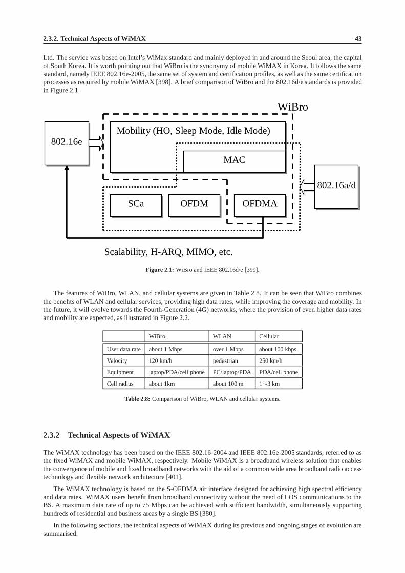
2.3.2. Technical Aspects of WiMAX 43
Ltd. The service was based on Intel’s WiMax standard and mainly deployed in and around the Seoul area, the capitalof South Korea. It is worth pointing out that WiBro is the synonymy of mobile WiMAX in Korea. It follows the samestandard, namely IEEE 802.16e-2005, the same set of system and certification profiles, as well as the same certificationprocesses as required by mobile WiMAX [398]. A brief comparison of WiBro and the 802.16d/e standards is providedin Figure 2.1.
Mobility (HO, Sleep Mode, Idle Mode) 802.16e
MAC
802.16a/d
SCa OFDM OFDMA
Scalability, H-ARQ, MIMO, etc.
WiBro
Figure 2.1: WiBro and IEEE 802.16d/e [399].
The features of WiBro, WLAN, and cellular systems are given in Table 2.8. It can be seen that WiBro combinesthe benefits of WLAN and cellular services, providing high data rates, while improving the coverage and mobility. Inthe future, it will evolve towards the Fourth-Generation (4G) networks, where the provision of even higher data ratesand mobility are expected, as illustrated in Figure 2.2.
WiBro WLAN Cellular
User data rate about 1 Mbps over 1 Mbps about 100 kbps
Velocity 120 km/h pedestrian 250 km/h
Equipment laptop/PDA/cell phone PC/laptop/PDA PDA/cell phone
Cell radius about 1km about 100 m 1∼3 km
Table 2.8: Comparison of WiBro, WLAN and cellular systems.
2.3.2 Technical Aspects of WiMAX
The WiMAX technology has been based on the IEEE 802.16-2004 and IEEE 802.16e-2005 standards, referred to asthe fixed WiMAX and mobile WiMAX, respectively. Mobile WiMAXis a broadband wireless solution that enablesthe convergence of mobile and fixed broadband networks with the aid of a common wide area broadband radio accesstechnology and flexible network architecture [401].
The WiMAX technology is based on the S-OFDMA air interface designed for achieving high spectral efficiencyand data rates. WiMAX users benefit from broadband connectivity without the need of LOS communications to theBS. A maximum data rate of up to 75 Mbps can be achieved with sufficient bandwidth, simultaneously supportinghundreds of residential and business areas by a single BS [380].
In the following sections, the technical aspects of WiMAX during its previous and ongoing stages of evolution aresummarised.

44 Chapter2. OFDM Standards
WiBro
4G Services
5 GHz WLAN 2.4 GHz
WLAN
3G
CDMA W-CDMA
2G
Cellular PCS
Data Rate
Mobility
1996 2000
2005 2010
High
Medium
Pedestrian
Stationary
Voice Text Image Graphic
Video High-Quality Multimedia Video
Streaming
Cordless Phone
Figure 2.2: WiBro service evolvement [400].
2.3.2.1 WiMAX-I: 802.16-2004 and 802.16e-2005
2.3.2.1.1 OFDMA System Configuration
The concept of scalability was introduced in the IEEE 802.16WirelessMAN-OFDMA [385] mode by the 802.16 TaskGroup e (TGe). The S-OFDMA architecture supports a wide range of bandwidth, which spans from 1.25 to 20 MHzcombined with fixed subcarrier spacing for both fixed and portable/mobile uses, in order to flexibly address the needfor various spectrum allocation and application requirements.
The scalability is achieved by adjusting the Fast Fourier Transform (FFT) size for various channel bandwidths. Inaddition to this, 802.16e supports Adaptive Modulation andCoding (AMC) subchannels, Hybrid Automatic RepeatRequest (HARQ), efficient uplink subchannelisation, MIMO-aided transmit/receive diversity, etc [402]. Table 2.9summarises the key parameters of 802.16e S-OFDMA [385].
Parameters Values
System Channel Bandwidth (MHz) 5 10 8.75 7
Sampling Frequency (Fs in MHz) 5.6 11.2 10 8
FFT Size (Nfft ) 512 1024 1024 1024
Number of Sub-Channels 8 16 16 16
Subcarrier Frequency Spacing (∆ f ) (KHz) 10.94 9.77 7.81
Useful Symbol Time (Tb = 1/∆ f ) (µs) 91.4 102.4 128
Guard Time (Tg = Tb/8) (µs) 11.4 12.8 16
OFDMA Symbol Duration (Ts = Tb + Tg) (µs) 102.9 115.2 144
Frame Duration (ms) 5 5 5
Number of OFDMA Symbols per Frame 48 43 34
Table 2.9: WiMAX Release-1 parameters.

2.3.2. Technical Aspects of WiMAX 45
2.3.2.1.2 Frame Structure
OFDMA is used for both DL and UL transmissions in 802.16e. TheOFDMA PHY mode is based on one of theFFT sizes: 2048 (backward compatible to 802.16-2004 [56]),1024, 512, and 128. This facilitates the support of thevarious channel bandwidths. The MS may implement a scanningand search mechanism to detect the DL signal, whenperforming initial network entry, and this may include the detection of the dynamically configured FFT size and thechannel bandwidth employed by the BS.
In licensed bands, the duplexing method shall be either FDD or TDD. FDD MSs may be half-duplex FDD (H-FDD). In license-exempt bands, the duplexing method shall be TDD. Figure 2.3 shows an example of an OFDMAframe (with only mandatory zone) in TDD mode. The OFDMA framemay include multiple zones, such as PartialUsage of Subchannels (PUSC), Full Usage of Subchannels (FUSC), PUSC with all subchannels, optional FUSC,AMC, etc. The transition between zones is indicated in the DL-Map by the standardised parameter STCDL ZoneInformation Element (IE) or AASDL IE [385]. No DL-MAP or UL-MAP allocations can span over multiple zones.Figure 2.4 depicts an OFDMA frame with multiple zones.
Figure 2.3: Example of a TDD OFDMA frame (with only mandatory zone) [385]. FCH: Feedback Channel; TTG:Transmit Transition Gap; RTG: Receive Transition Gap.
2.3.2.1.3 Subcarrier Mapping
For the OFDMA profile of 802.16e, we haveFs = f loor(n · BW/8000) · 8000 (Hz), whereFs is the samplingfrequency andn is the sampling factor, which is dependent on the bandwidthBW. After removing the frequency-domain guard tones or virtual subcarriers fromNfft , which is the FFT size, one obtains the set of “used” subcarriersNused. These used subcarriers are allocated to pilot subcarriersand data subcarriers for both UL and DL.
However, there is a difference between the different possible zones. For the DL FUSC and PUSC, the pilot tonesare allocated first, followed by the mapping of data subcarriers to subchannels (i.e. subbands) exclusively allocated fordata. For PUSC in the UL, the set of used subcarriers is first partitioned into subchannels and then the pilot subcarriersare allocated from within each subchannel. Thus, in FUSC, there is one set of common pilot subcarriers for the entirefrequency band, while in PUSC of the DL, there is one set of common pilot subcarriers in each major group, whichis constituted by a few subchannels. By contrast, in PUSC of the UL, each subchannel contains its own set of pilotsubcarriers. After mapping all pilots to the associated subchannels, the remaining used subcarriers will be groupedinto data subchannels. For the different zones mentioned above, however, the corresponding subcarrier allocation
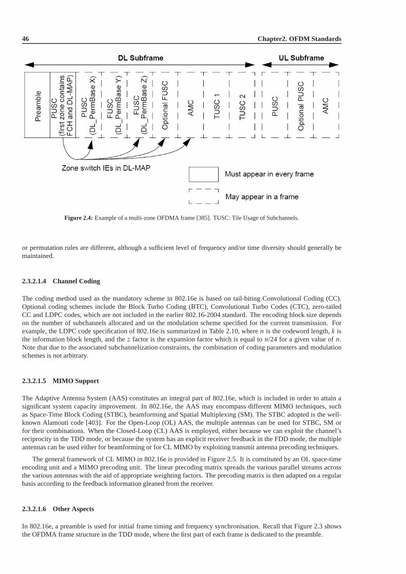
46 Chapter2. OFDM Standards
Figure 2.4: Example of a multi-zone OFDMA frame [385]. TUSC: Tile Usage of Subchannels.
or permutation rules are different, although a sufficient level of frequency and/or time diversity should generally bemaintained.
2.3.2.1.4 Channel Coding
The coding method used as the mandatory scheme in 802.16e is based on tail-biting Convolutional Coding (CC).Optional coding schemes include the Block Turbo Coding (BTC), Convolutional Turbo Codes (CTC), zero-tailedCC and LDPC codes, which are not included in the earlier 802.16-2004 standard. The encoding block size dependson the number of subchannels allocated and on the modulationscheme specified for the current transmission. Forexample, the LDPC code specification of 802.16e is summarized in Table 2.10, wheren is the codeword length,k isthe information block length, and thez factor is the expansion factor which is equal ton/24 for a given value ofn.Note that due to the associated subchannelization constraints, the combination of coding parameters and modulationschemes is not arbitrary.
2.3.2.1.5 MIMO Support
The Adaptive Antenna System (AAS) constitutes an integral part of 802.16e, which is included in order to attain asignificant system capacity improvement. In 802.16e, the AAS may encompass different MIMO techniques, suchas Space-Time Block Coding (STBC), beamforming and SpatialMultiplexing (SM). The STBC adopted is the well-known Alamouti code [403]. For the Open-Loop (OL) AAS, the multiple antennas can be used for STBC, SM orfor their combinations. When the Closed-Loop (CL) AAS is employed, either because we can exploit the channel’sreciprocity in the TDD mode, or because the system has an explicit receiver feedback in the FDD mode, the multipleantennas can be used either for beamforming or for CL MIMO by exploiting transmit antenna precoding techniques.
The general framework of CL MIMO in 802.16e is provided in Figure 2.5. It is constituted by an OL space-timeencoding unit and a MIMO precoding unit. The linear precoding matrix spreads the various parallel streams acrossthe various antennas with the aid of appropriate weighting factors. The precoding matrix is then adapted on a regularbasis according to the feedback information gleaned from the receiver.
2.3.2.1.6 Other Aspects
In 802.16e, a preamble is used for initial frame timing and frequency synchronisation. Recall that Figure 2.3 showsthe OFDMA frame structure in the TDD mode, where the first partof each frame is dedicated to the preamble.
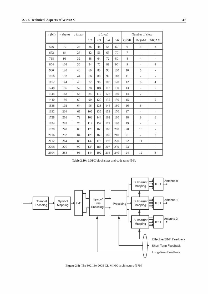
2.3.2. Technical Aspects of WiMAX 47
n (bit) n (byte) z factor k (byte) Number of slots
1/2 2/3 3/4 5/6 QPSK 16QAM 64QAM
576 72 24 36 48 54 60 6 3 2
672 84 28 42 56 63 70 7 - -
768 96 32 48 64 72 80 8 4 -
864 108 36 54 72 81 90 9 - 3
960 120 40 60 80 90 100 10 5 -
1056 132 44 66 88 99 110 11 - -
1152 144 48 72 96 108 120 12 6 4
1248 156 52 78 104 117 130 13 - -
1344 168 56 84 112 126 140 14 7 -
1440 180 60 90 120 135 150 15 - 5
1536 192 64 96 128 144 160 16 8 -
1632 204 68 102 136 153 170 17 - -
1728 216 72 108 144 162 180 18 9 6
1824 228 76 114 152 171 190 19 - -
1920 240 80 120 160 180 200 20 10 -
2016 252 84 126 168 189 210 21 - 7
2112 264 88 132 176 198 220 22 11 -
2208 276 92 138 184 207 230 23 - -
2304 288 96 144 192 216 240 24 12 8
Table 2.10:LDPC block sizes and code rates [56].
Figure 2.5: The 802.16e-2005 CL MIMO architecture [379].
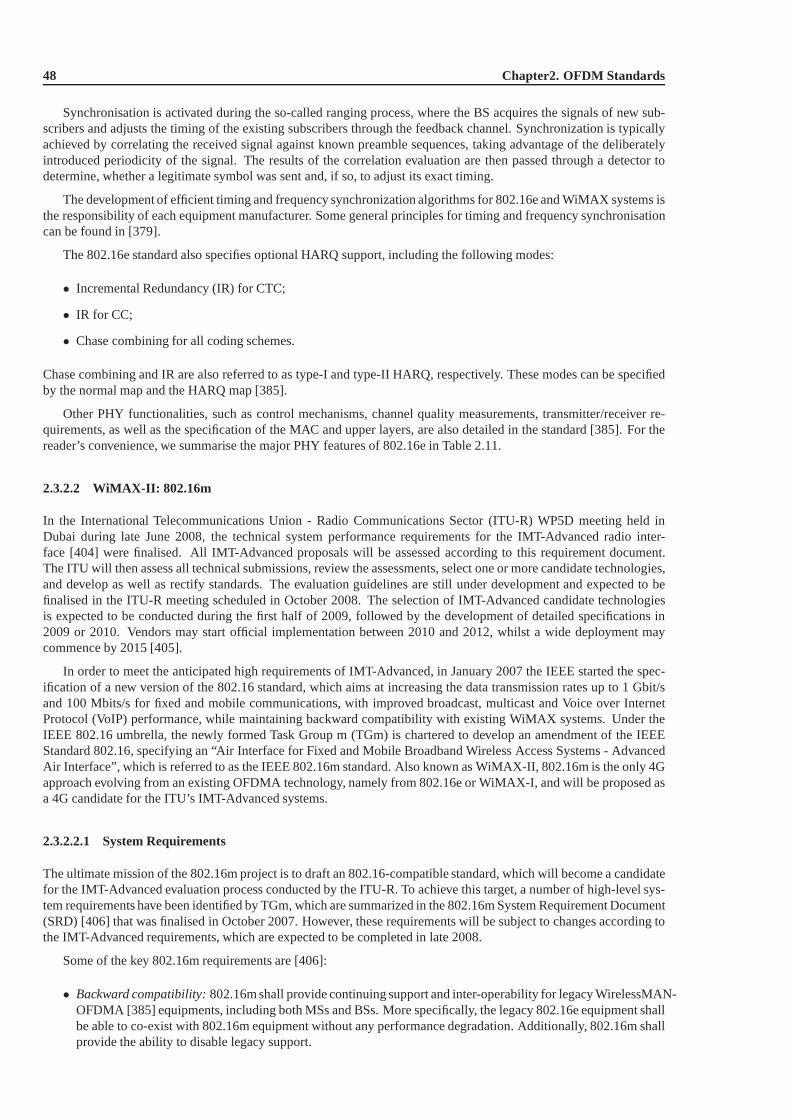
48 Chapter2. OFDM Standards
Synchronisation is activated during the so-called rangingprocess, where the BS acquires the signals of new sub-scribers and adjusts the timing of the existing subscribersthrough the feedback channel. Synchronization is typicallyachieved by correlating the received signal against known preamble sequences, taking advantage of the deliberatelyintroduced periodicity of the signal. The results of the correlation evaluation are then passed through a detector todetermine, whether a legitimate symbol was sent and, if so, to adjust its exact timing.
The development of efficient timing and frequency synchronization algorithms for 802.16e and WiMAX systems isthe responsibility of each equipment manufacturer. Some general principles for timing and frequency synchronisationcan be found in [379].
The 802.16e standard also specifies optional HARQ support, including the following modes:
• Incremental Redundancy (IR) for CTC;
• IR for CC;
• Chase combining for all coding schemes.
Chase combining and IR are also referred to as type-I and type-II HARQ, respectively. These modes can be specifiedby the normal map and the HARQ map [385].
Other PHY functionalities, such as control mechanisms, channel quality measurements, transmitter/receiver re-quirements, as well as the specification of the MAC and upper layers, are also detailed in the standard [385]. For thereader’s convenience, we summarise the major PHY features of 802.16e in Table 2.11.
2.3.2.2 WiMAX-II: 802.16m
In the International Telecommunications Union - Radio Communications Sector (ITU-R) WP5D meeting held inDubai during late June 2008, the technical system performance requirements for the IMT-Advanced radio inter-face [404] were finalised. All IMT-Advanced proposals will be assessed according to this requirement document.The ITU will then assess all technical submissions, review the assessments, select one or more candidate technologies,and develop as well as rectify standards. The evaluation guidelines are still under development and expected to befinalised in the ITU-R meeting scheduled in October 2008. Theselection of IMT-Advanced candidate technologiesis expected to be conducted during the first half of 2009, followed by the development of detailed specifications in2009 or 2010. Vendors may start official implementation between 2010 and 2012, whilst a wide deployment maycommence by 2015 [405].
In order to meet the anticipated high requirements of IMT-Advanced, in January 2007 the IEEE started the spec-ification of a new version of the 802.16 standard, which aims at increasing the data transmission rates up to 1 Gbit/sand 100 Mbits/s for fixed and mobile communications, with improved broadcast, multicast and Voice over InternetProtocol (VoIP) performance, while maintaining backward compatibility with existing WiMAX systems. Under theIEEE 802.16 umbrella, the newly formed Task Group m (TGm) is chartered to develop an amendment of the IEEEStandard 802.16, specifying an “Air Interface for Fixed andMobile Broadband Wireless Access Systems - AdvancedAir Interface”, which is referred to as the IEEE 802.16m standard. Also known as WiMAX-II, 802.16m is the only 4Gapproach evolving from an existing OFDMA technology, namely from 802.16e or WiMAX-I, and will be proposed asa 4G candidate for the ITU’s IMT-Advanced systems.
2.3.2.2.1 System Requirements
The ultimate mission of the 802.16m project is to draft an 802.16-compatible standard, which will become a candidatefor the IMT-Advanced evaluation process conducted by the ITU-R. To achieve this target, a number of high-level sys-tem requirements have been identified by TGm, which are summarized in the 802.16m System Requirement Document(SRD) [406] that was finalised in October 2007. However, these requirements will be subject to changes according tothe IMT-Advanced requirements, which are expected to be completed in late 2008.
Some of the key 802.16m requirements are [406]:
• Backward compatibility:802.16m shall provide continuing support and inter-operability for legacy WirelessMAN-OFDMA [385] equipments, including both MSs and BSs. More specifically, the legacy 802.16e equipment shallbe able to co-exist with 802.16m equipment without any performance degradation. Additionally, 802.16m shallprovide the ability to disable legacy support.
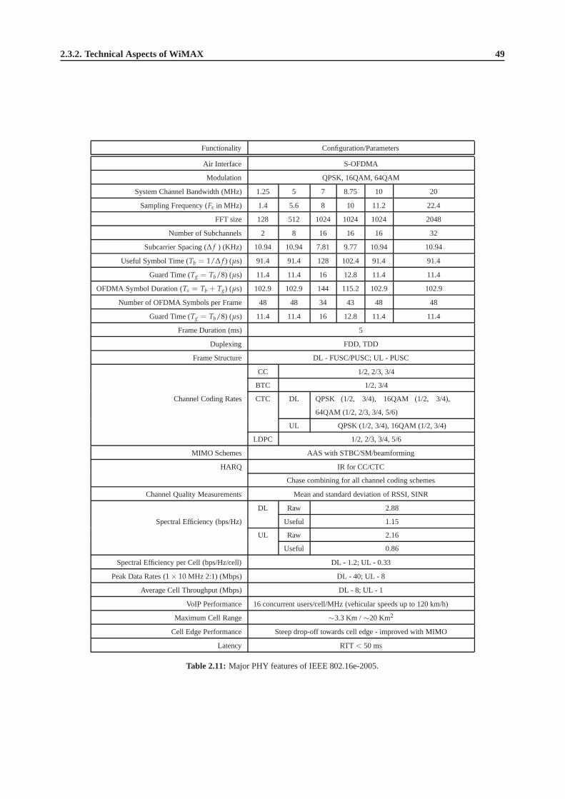
2.3.2. Technical Aspects of WiMAX 49
Functionality Configuration/Parameters
Air Interface S-OFDMA
Modulation QPSK, 16QAM, 64QAM
System Channel Bandwidth (MHz) 1.25 5 7 8.75 10 20
Sampling Frequency (Fs in MHz) 1.4 5.6 8 10 11.2 22.4
FFT size 128 512 1024 1024 1024 2048
Number of Subchannels 2 8 16 16 16 32
Subcarrier Spacing (∆ f ) (KHz) 10.94 10.94 7.81 9.77 10.94 10.94
Useful Symbol Time (Tb = 1/∆ f ) (µs) 91.4 91.4 128 102.4 91.4 91.4
Guard Time (Tg = Tb/8) (µs) 11.4 11.4 16 12.8 11.4 11.4
OFDMA Symbol Duration (Ts = Tb + Tg) (µs) 102.9 102.9 144 115.2 102.9 102.9
Number of OFDMA Symbols per Frame 48 48 34 43 48 48
Guard Time (Tg = Tb/8) (µs) 11.4 11.4 16 12.8 11.4 11.4
Frame Duration (ms) 5
Duplexing FDD, TDD
Frame Structure DL - FUSC/PUSC; UL - PUSC
CC 1/2, 2/3, 3/4
BTC 1/2, 3/4
Channel Coding Rates CTC DL QPSK (1/2, 3/4), 16QAM (1/2, 3/4),
64QAM (1/2, 2/3, 3/4, 5/6)
UL QPSK (1/2, 3/4), 16QAM (1/2, 3/4)
LDPC 1/2, 2/3, 3/4, 5/6
MIMO Schemes AAS with STBC/SM/beamforming
HARQ IR for CC/CTC
Chase combining for all channel coding schemes
Channel Quality Measurements Mean and standard deviation of RSSI, SINR
DL Raw 2.88
Spectral Efficiency (bps/Hz) Useful 1.15
UL Raw 2.16
Useful 0.86
Spectral Efficiency per Cell (bps/Hz/cell) DL - 1.2; UL - 0.33
Peak Data Rates (1 × 10 MHz 2:1) (Mbps) DL - 40; UL - 8
Average Cell Throughput (Mbps) DL - 8; UL - 1
VoIP Performance 16 concurrent users/cell/MHz (vehicular speeds up to 120 km/h)
Maximum Cell Range ∼3.3 Km /∼20 Km2
Cell Edge Performance Steep drop-off towards cell edge - improved with MIMO
Latency RTT < 50 ms
Table 2.11:Major PHY features of IEEE 802.16e-2005.

50 Chapter2. OFDM Standards
• Services:802.16m should support legacy services more efficiently than the WirelessMAN-OFDMA ReferenceSystem [407] as well as facilitate the introduction of new/emerging types of services. Flexible services havingdifferent QoS levels should be supported, as required by next-generation mobile networks.
• Operating frequencies and bandwidths:802.16m systems shall operate at RF frequencies less than 6 GHz andbe deployable in licensed spectrum allocated to the mobile and fixed broadband services. It shall be able tooperate in frequency bands identified for IMT-Advanced. An 802.16m-compliant system shall be capable ofcoexisting with other IMT-Advanced or IMT-2000 technologies. Scalable bandwidths ranging from 5 to 20MHz shall be supported.
• Support of advanced antenna techniques:802.16m shall support MIMO, beamforming operation or otherad-vanced antenna techniques for single-user and multi-user scenarios. The minimum number of transmit andreceive antennas for the BS and the MS are2 × 2 and1 × 2, respectively.
• Minimum peak data rate:The baseline DL and UL peak data rates are 8 and 2.8 bps/Hz, respectively. Whenmore antennas are used, the rate requirements become 15 and 5.6 bps/Hz for the DL and UL, respectively.
• Co-existence and co-deployment with other Radio Access Technologies (RATs):802.16m shall support inter-working functionality, providing efficient handover and allowing co-deployment with other RATs, includingIEEE 802.11 [371], 3GPP GSM/EDGE, UTRA/E-UTRA, and 3GPP2 CDMA2000.
• Mobility and coverage:802.16m shall support vehicular speeds of up to 350 km/h and provide a cell coverageof up to even 100 km. For lower mobility and for areas closer tothe cell centre, the system’s performance shouldbe optimised and degrade gracefully as a function of the vehicular speed and/or the distance from the cell centre.
• MBS, Location Based Service (LBS), relaying and self-organisation support:802.16m shall support EnhancedMulticast and Broadcast Services (E-MBS) for IMT-Advancedmultimedia multicast broadcast services in aspectrally efficient manner, provide mechanisms to enable multi-hop relays including those that may involveadvanced multiple antenna techniques, and support self-organizing mechanisms including self-configurationand self-optimisation.
For more details on the various aspects of the 802.16m systemrequirements, we refer to Tables 2.12, 2.13, 2.14and 2.15.
2.3.2.2.2 System Description
In January 2008, TGm started to develop the 802.16m System Description Document (SDD) [409], which aims toprovide a detailed specification of the 802.16m system that meets the requirements set by 802.16m SRD [406]. Sincethe commencement of the SDD development, significant efforts have been made by the entire project group. A numberof Rapporteur Groups (RG) are formed to focus on dedicated topics, for example the frame structure RG, the multipleaccess RG, etc. Although technical discussions are still ongoing, some high level descriptions of the 802.16m systemare already in place.
The Network Reference Model (NRM) of the 802.16m system is shown in Figure 2.6. The NRM is a logical repre-sentation of the overall network architecture. It identifies functional entities and reference points used for ensuring thatinter-operability is achieved between functional entities, such as the MS, Access Service Network (ASN) and Con-nectivity Service Network (CSN) [409]. The ASN is defined as afull set of network functions, including 802.16e/mLayer-1 (L1) and Layer-2 (L2) connectivity between an 802.16m BS and an 802.16e/m MS, transfer of Authentication,Authorization, and Accounting (AAA) messages to an 802.16e/m subscriber’s Home Network Service Provider (H-NSP), network discovery and selection of the subscriber’s preferred NSP, relay functionality for establishing Layer-3(L3) connectivity with an 802.16e/m MS, RRM, ASN/CSN anchored mobility, paging, and so on [409].
In Figure 2.7, an illustration of the 802.16m MS’s state transition process is provided [409]. When an MS isswitched on, it will enter the initialization state, where the cell selection process is performed by scanning and thensynchronizing to a BS’s preamble, followed by acquiring thesystem configuration information through the BroadcastChannel (BCH). If this is successful, the MS invokes the network entry procedure, requesting for the entry to theselected BS, which results in a number of access state procedures. More specifically, the ranging process is activatedfirst to attain UL synchronization, followed by a ‘capability-negotiation’ step with the BS. Then the authenticationand authorization process will be invoked and then the MS will be registered by the BS through the allocation ofan 802.16m specific ID. Upon successfully performing the access-state operations of Figure 2.7, the MS will enterthe connected state, which consists of three modes, namely the sleep mode, the active mode and the scanning mode.

2.3.2. Technical Aspects of WiMAX 51
Requirement Description
Backward compati-
bility
The legacy 802.16e equipment shall be able to co-exist with 802.16m equipment with-
out performance degradation. 802.16m shall provide the ability to disable legacy sup-
port.
Complexity 802.16m should minimize complexity of the architecture andprotocols and avoid
excessive system complexity. Only the enhancements in those areas where the
WirelessMAN-OFDMA Reference System [407] fails to meet therequirements should
be provided.
Services 802.16m should support legacy services more efficiently than the WirelessMAN-
OFDMA Reference System [407] and facilitate new/emerging services. Flexible ser-
vices with different QoS levels should be supported.
Operating frequen-
cies
802.16m systems shall operate in RF frequencies less than 6 GHz in licensed spectrum.
It shall be able to operate in frequencies identified for IMT-Advanced. An 802.16m
compliant system shall be capable of coexisting with other IMT-Advanced or IMT-2000
technologies.
Operating band-
widths
Scalable bandwidths from 5 to 20 MHz shall be supported.
Duplex schemes Both TDD and FDD shall be supported, where the FDD mode shall support both full-
duplex and half-duplex (H-FDD) MS operation.
Support of ad-
vanced antenna
techniques
802.16m shall support MIMO, beamforming or other advanced antenna techniques for
single-user and multi-user scenarios. The minimum number of transmit and receive
antennas for BS and MS are2 × 2 and1 × 2, respectively.
Table 2.12:The major general requirements for IEEE 802.16m.
IEEE 802.16m Scope
Access Service Network
R2 (logical interface)
16mBS
16m BS
R1
Other Access Service Networks
R4
Connectivity Service Network
Connectivity Service Network
R3 R5
Access Service Provider Network (Internet)
Access Service Provider Network (Internet)
Home Network Service Provider
Visited Network Service Provider
16m BS
16e/m MS
Layer 1 and Layer 2 specified by IEEE 802.16m
16e/m MS
R1
Figure 2.6: The NRM of IEEE 802.16m [409].

52 Chapter2. OFDM Standards
Requirement Description
Peak data rate Baseline DL (2 × 2): 8.0
(bps/Hz) UL (1 × 2): 2.8
Target DL (4 × 4): 15.0
UL (2 × 4): 5.6
Latency (ms) Data latency 10
State transition latency 100
Handover interruption time 30 (intra-frequency mode)
100 (inter-frequency mode)
QoS 802.16m shall support a range of QoS classes and new applications. When possible, the QoS
level should be maintained during handover with other RATs.
RRM Advanced, efficient RRM shall be supported by 802.16m using appropriate measurement or
reporting, interference management and flexible resource allocation mechanisms.
Handover Handover between 802.16m, legacy systems, and/or other RATs and IEEE 802.21 Media Inde-
pendent Handover (MIH) Services [408] shall be supported.
Broadcast E-MBS using a dedicated carrier shall be supported. Switching between broadcast and unicast
services shall be supported.
Overhead 802.16m should reduce both user overhead and system overhead when compared to legacy
systems without compromising the overall system performance.
Power efficiency 802.16m shall provide support for enhanced power saving functionality for all services and
applications.
Coexistence with
other RATs
802.16m shall support efficient handover to other RATs, including IEEE 802.11 [371], 3GPP
GSM/EDGE, UTRA/E-UTRA, and 3GPP2 CDMA2000.
Table 2.13:The major functional requirements for IEEE 802.16m.
Requirement Description
User/Sector
throughputs
These should be two times as the WirelessMAN-OFDMA Reference System [407].
Mobility 0-10 km/h Optimised system performance
10-120 km/h Graceful performance degradation as a function of vehicular speed
120-350 km/h Connection should be maintained
Cell coverage 0-5 km Optimized system performance
5-30 km Graceful degradation in system/edge spectral efficiency
30-100 km System should be functional (thermal noise limited scenario)
MBS/LBS sup-
port
Minimum performance requirements for E-MBS (spectral efficiency over 95% coverage areas) are
4 bps/Hz and 2 bps/Hz for an inter-site distance of 0.5 km and 1.5 km, respectively. Specific LBS
requirements should also be met.
Table 2.14:The major performance requirements for IEEE 802.16m.
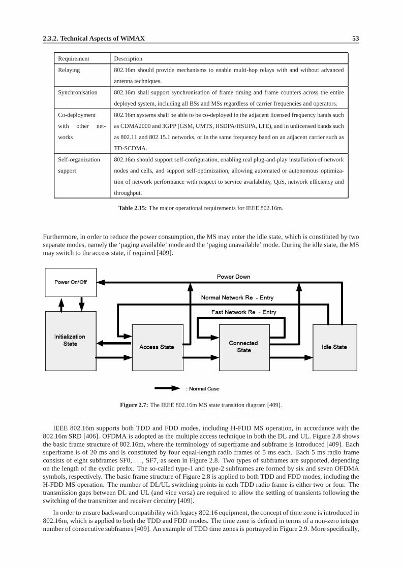
2.3.2. Technical Aspects of WiMAX 53
Requirement Description
Relaying 802.16m should provide mechanisms to enable multi-hop relays with and without advanced
antenna techniques.
Synchronisation 802.16m shall support synchronisation of frame timing and frame counters across the entire
deployed system, including all BSs and MSs regardless of carrier frequencies and operators.
Co-deployment
with other net-
works
802.16m systems shall be able to be co-deployed in the adjacent licensed frequency bands such
as CDMA2000 and 3GPP (GSM, UMTS, HSDPA/HSUPA, LTE), and in unlicensed bands such
as 802.11 and 802.15.1 networks, or in the same frequency band on an adjacent carrier such as
TD-SCDMA.
Self-organization
support
802.16m should support self-configuration, enabling real plug-and-play installation of network
nodes and cells, and support self-optimization, allowing automated or autonomous optimiza-
tion of network performance with respect to service availability, QoS, network efficiency and
throughput.
Table 2.15:The major operational requirements for IEEE 802.16m.
Furthermore, in order to reduce the power consumption, the MS may enter the idle state, which is constituted by twoseparate modes, namely the ‘paging available’ mode and the ‘paging unavailable’ mode. During the idle state, the MSmay switch to the access state, if required [409].
Figure 2.7: The IEEE 802.16m MS state transition diagram [409].
IEEE 802.16m supports both TDD and FDD modes, including H-FDD MS operation, in accordance with the802.16m SRD [406]. OFDMA is adopted as the multiple access technique in both the DL and UL. Figure 2.8 showsthe basic frame structure of 802.16m, where the terminologyof superframe and subframe is introduced [409]. Eachsuperframe is of 20 ms and is constituted by four equal-length radio frames of 5 ms each. Each 5 ms radio frameconsists of eight subframes SF0,. . ., SF7, as seen in Figure 2.8. Two types of subframes are supported, dependingon the length of the cyclic prefix. The so-called type-1 and type-2 subframes are formed by six and seven OFDMAsymbols, respectively. The basic frame structure of Figure2.8 is applied to both TDD and FDD modes, including theH-FDD MS operation. The number of DL/UL switching points in each TDD radio frame is either two or four. Thetransmission gaps between DL and UL (and vice versa) are required to allow the settling of transients following theswitching of the transmitter and receiver circuitry [409].
In order to ensure backward compatibility with legacy 802.16 equipment, the concept of time zone is introduced in802.16m, which is applied to both the TDD and FDD modes. The time zone is defined in terms of a non-zero integernumber of consecutive subframes [409]. An example of TDD time zones is portrayed in Figure 2.9. More specifically,
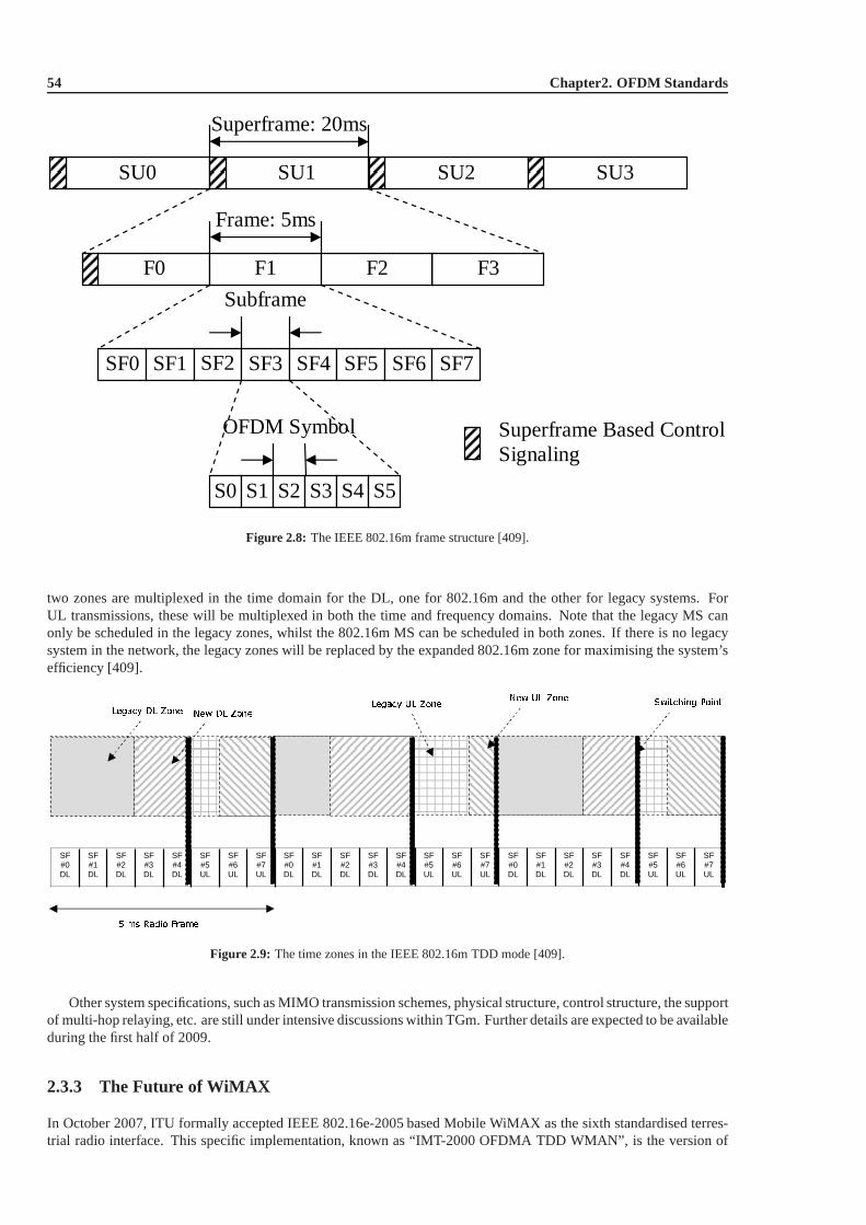
54 Chapter2. OFDM Standards
SU0 SU1 SU2 SU3
F0 F1 F2 F3
SF0 SF1 SF2
SF3 SF4 SF5 SF6 SF7
Frame: 5ms
Superframe: 20ms
Subframe
Superframe Based Control Signaling
S0 S1 S2 S3 S4 S5
OFDM Symbol
Figure 2.8: The IEEE 802.16m frame structure [409].
two zones are multiplexed in the time domain for the DL, one for 802.16m and the other for legacy systems. ForUL transmissions, these will be multiplexed in both the timeand frequency domains. Note that the legacy MS canonly be scheduled in the legacy zones, whilst the 802.16m MS can be scheduled in both zones. If there is no legacysystem in the network, the legacy zones will be replaced by the expanded 802.16m zone for maximising the system’sefficiency [409].
SF#7 UL
SF#6 UL
SF#5 UL
SF#4 DL
SF#3 DL
SF#2 DL
SF#1 DL
SF#0 DL
SF#7 UL
SF#6 UL
SF#5 UL
SF#4 DL
SF#3 DL
SF#2 DL
SF#1 DL
SF#0 DL
SF#7 UL
SF#6 UL
SF#5 UL
SF#4 DL
SF#3 DL
SF#2 DL
SF#1 DL
SF#0 DL
Figure 2.9: The time zones in the IEEE 802.16m TDD mode [409].
Other system specifications, such as MIMO transmission schemes, physical structure, control structure, the supportof multi-hop relaying, etc. are still under intensive discussions within TGm. Further details are expected to be availableduring the first half of 2009.
2.3.3 The Future of WiMAX
In October 2007, ITU formally accepted IEEE 802.16e-2005 based Mobile WiMAX as the sixth standardised terres-trial radio interface. This specific implementation, knownas “IMT-2000 OFDMA TDD WMAN”, is the version of
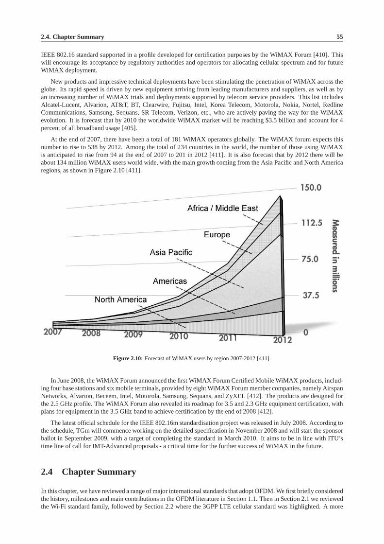
2.4. Chapter Summary 55
IEEE 802.16 standard supported in a profile developed for certification purposes by the WiMAX Forum [410]. Thiswill encourage its acceptance by regulatory authorities and operators for allocating cellular spectrum and for futureWiMAX deployment.
New products and impressive technical deployments have been stimulating the penetration of WiMAX across theglobe. Its rapid speed is driven by new equipment arriving from leading manufacturers and suppliers, as well as byan increasing number of WiMAX trials and deployments supported by telecom service providers. This list includesAlcatel-Lucent, Alvarion, AT&T, BT, Clearwire, Fujitsu, Intel, Korea Telecom, Motorola, Nokia, Nortel, RedlineCommunications, Samsung, Sequans, SR Telecom, Verizon, etc., who are actively paving the way for the WiMAXevolution. It is forecast that by 2010 the worldwide WiMAX market will be reaching $3.5 billion and account for 4percent of all broadband usage [405].
At the end of 2007, there have been a total of 181 WiMAX operators globally. The WiMAX forum expects thisnumber to rise to 538 by 2012. Among the total of 234 countriesin the world, the number of those using WiMAXis anticipated to rise from 94 at the end of 2007 to 201 in 2012 [411]. It is also forecast that by 2012 there will beabout 134 million WiMAX users world wide, with the main growth coming from the Asia Pacific and North Americaregions, as shown in Figure 2.10 [411].
Figure 2.10: Forecast of WiMAX users by region 2007-2012 [411].
In June 2008, the WiMAX Forum announced the first WiMAX Forum Certified Mobile WiMAX products, includ-ing four base stations and six mobile terminals, provided byeight WiMAX Forum member companies, namely AirspanNetworks, Alvarion, Beceem, Intel, Motorola, Samsung, Sequans, and ZyXEL [412]. The products are designed forthe 2.5 GHz profile. The WiMAX Forum also revealed its roadmapfor 3.5 and 2.3 GHz equipment certification, withplans for equipment in the 3.5 GHz band to achieve certification by the end of 2008 [412].
The latest official schedule for the IEEE 802.16m standardisation project was released in July 2008. According tothe schedule, TGm will commence working on the detailed specification in November 2008 and will start the sponsorballot in September 2009, with a target of completing the standard in March 2010. It aims to be in line with ITU’stime line of call for IMT-Advanced proposals - a critical time for the further success of WiMAX in the future.
2.4 Chapter Summary
In this chapter, we have reviewed a range of major international standards that adopt OFDM. We first briefly consideredthe history, milestones and main contributions in the OFDM literature in Section 1.1. Then in Section 2.1 we reviewedthe Wi-Fi standard family, followed by Section 2.2 where the3GPP LTE cellular standard was highlighted. A more
56 Chapter2. OFDM Standards
detailed introduction of WiMAX was presented in Section 2.3. More specifically, we briefly reviewed the history ofWiMAX in Section 2.3.1, spanning from the early IEEE 802.16 standards in Section 2.3.1.2 to their recent amendmentsin Sections 2.3.1.2.1, 2.3.1.2.2, and 2.3.1.2.3. Early WiMAX solutions were based on the WirelessMAN OFDM PHYof 802.16-2004, which is also known as “fixed WiMAX”. By contrast, as the successor of 802.16-2004, the 802.16estandard incorporates mobility support and thus it is referred to as “mobile WiMAX”. In Section 2.3.1.3, the historicbackground of the WiMAX Forum was summarized, where its mission and achievements were briefly reviewed.Furthermore, we provided a brief introduction of the KoreanWiMAX standard WiBro in Section 2.3.1.4. Being theworld’s largest commercial mobile WiMAX deployment, the WiBro network is accelerating its evolution towards the4G era.
In Section 2.3.2, we focused our attention on the technical aspects of WiMAX. More specifically, the major PHYspecifications of WiMAX-I, which were based on 802.16-2004 and 802.16e, was provided in Section 2.3.2.1. Theseincluded the OFDMA system configuration, frame structure, subcarrier mapping, channel coding, MIMO support, etc.Moreover, in Section 2.3.2.2 the technical requirements and system description of the 802.16m draft standard waspresented. It is expected that the 802.16m standard will be finalised in March 2010, although it is still in its infancy atthe time of writing. Finally, a brief discussion of the progress and future of WiMAX was offered in Section 2.3.3.

Part I
Coherently Detected SDMA-OFDMSystems


Chapter3Channel Coding Assisted STBC-OFDMSystems
3.1 Introduction
Increasing market expectations for third-generation mobile radio systems show a great demand for a wider range ofservices spanning from voice to high-rate data services required for supporting mobile multimedia communications.This leads to higher technical specifications for existing and future communication systems, which have to supportdata rates as high as 144Kb/s in vehicular, 384Kb/s in outdoor-to-indoor and 2Mb/s in indoor and picocelluar environ-ments [413].
The employment of multiple antennas constitutes an effective way of achieving an increased capacity. The classicapproach is to use multiple receiver antennas and exploit Maximum Ratio Combining (MRC) of the received signalsfor the sake of improving the system’s performance [414, 415]. However, the performance improvement of MRC isachieved at the cost of increasing the complexity of the Mobile Stations (MSs). Alternatively, MRC may be employedat the Base Stations (BSs), which support numerous MSs. While this scheme provides diversity gain for the BSs’receivers, the MSs cannot benefit from it.
Employing multiple transmitters, rather than receiver antennas at the BSs constitutes a further design option in thiscontext. Since transmitter diversity techniques are proposed for employment at the BSs, it is possible to enhance thesystem’s integrity by upgrading the BSs. Alamouti [403] introduced an attractive scheme, which uses two transmittersin conjunction with an arbitrary number of receivers for communications in non-dispersive Rayleigh fading channels.Tarokhet al. [416, 417] generalized Alamouti’s scheme to an arbitrary number of transmitters. These schemes intro-duced Space-Time Block Codes (STBCs), which show remarkable encoding and decoding simplicity, while achievinga good performance.
3.2 Space-Time Block Codes
In this section we will present the basic principles of space-time block codes. Before providing more details, let usfirst consider a simple space-time block coded system communicating over uncorrelated Rayleigh fading channels, asshown in Figure 3.1.
3.2.1 Alamouti’s G2 Space-Time Block Code
The system contains two transmitter antennas and one receiver antenna. The philosophy of Alamouti’sG2 space-timeblock code is as follows.
In a conceptually simple approach we could argue that the achieveable throughput of the system may be doubledwith the aid of the two transmitter antennas, if their signalcould be separated by the receiver. This task may be viewedas analogous to multiuser detection, where the two signals would arrive at the BS’s receiver from two geographically

60 Chapter3. Channel Coding Assisted STBC-OFDM Systems
Time Slot 1
1x2x−
1Tx
1 1 1 2 2 1y h x h x n= + +
2 1 2 2 1 2y hx h x n=− + +
Time Slot 2
Combiner
Maximum Likelihood
Detector
Channel
Estimator
1x
2Tx
2x
1h 2h
1n
2n
1h
2h1x
2x
1x 2x
Figure 3.1: Schematic of Alamouti’sG2 space-time block code.
separated users. From a simple conceptual perspective the Bell Labs Layered Space-Time (BLAST) transmissionscheme [106] adopts a similar principle for increasing the achievable throughput of multiple transmitter antenna basedsystems.
By contrast, Alamouti’s approach is different, since the aim is to achieve a diversity gain rather than to increase theachievable throughput. This is achieved by extending the duration of time allocated to the transmission of a symbol bya factor of two and transmitting two independently faded and‘appropriately transformed’ replicas of the symbol usingeach of the two antennas. The independence of the two channels may be ascertained by positioning the transmitterantennasTx 1 andTx 2 sufficiently far apart, for example at a distance of10λ, whereλ is the wavelength. Thus,during the first time slot, the information symbolsx1 andx2 are transmitted by transmitter antennaTx 1 andTx 2,respectively, and again each of the two symbols is transmitted through an independently faded channel. For the sakeof avoiding the channel-induced inter-symbol interference between the two time slots, both channels’ path gains areassumed to be constituted by a single propagation path givenby:
h1 = |h1| ejα1 (3.1)
h2 = |h2| ejα2 , (3.2)
where|h1|, |h2| are the fading magnitudes andα1, α2 are the corresponding phase rotations. The complex fadingenvelopes are assumed to remain constant during the two consecutive time slots [359], which is expressed as:
h1 = h1(t = 1) = h1(t = 2) (3.3)
h2 = h2(t = 1) = h2(t = 2). (3.4)

3.2.2. Encoding Algorithm 61
Therefore we receive the composite signaly1 constituted by the superposition of the two transmitted symbols throughboth channels:
y1 = h1x1 + h2x2 + n1, (3.5)
wheren1 is a complex noise sample. As mentioned above, during the second time slot, a transformed version of thesignalsx1 andx2 is transmitted. Since the consecutive time slots are not faded independently, no diversity gain wouldbe achieved, if we mapped these ‘transformed’ replicas ofx1 andx2 to the same transmitter antenna as during the firsttime slot. Hence we now swap the assignment of the time slots to transmitter antennas, since this way their independentfading may be ascertained. More explicitly, during the second time slot, the negative version of the conjugate ofx2
and the conjugate ofx1 are sent by transmitter antennaTx 1 andTx 2, respectively. However, as mentioned above,the envelopes of each of the channels associated with the twotransmitters are assumed to be the same as during thefirst time slot, hence we get the second transmitter’s signaly2 as:
y2 = −h1 x2 + h2x1 + n2, (3.6)
wheren2 is a complex noise sample. If the channels’ characteristicsare known to the receiver, i.e. we have a perfectchannel estimator, the information symbolsx1 andx2 can be readily separated in the combiner of Figure 3.1, yielding:
x1 = h1y1 + h2y2
= h1h1x1 + h1h2x2 + h1n1 − h2h1x2 + h2h2x1 + h2n2
=(
|h1|2 + |h2|2)
x1 + h1n1 + h2n2 (3.7)
x2 = h2y1 − h1y2
= h2h1x1 + h2h2x2 + h2n1 + h1h1x2 − h1h2x1 − h1n2
=(
|h1|2 + |h2|2)
x2 + h2n1 − h1n2, (3.8)
wherex1 andx2 are the extracted noisy signals. Thenx1 andx2 will be forwarded to the maximum likelihood detectorof Figure 3.1, which determines the most likely transmittedsymbols, namelyx1 and x2 by simply outputting thespecific legitimate transmitted symbol, which has the lowest Euclidean distance from the received channel-impairedsymbol [359].
The equations above, which are based on the one-receiver scheme, can be generalized to multiple-receiver aided
schemes, where the received signalyjt arriving at receiverj during time slott is [359]:
yjt =
p
∑i=1
hi,jxit + n
jt, (3.9)
wherep is the number of transmitters,hi,j is the complex-valued path gain between the transmitteri and receiverj, xit
is the space-time coded symbol transmitted by transmitteri during time slott, andnjt is the noise sample at receiverj
in time slott. Accordingly, the extracted noisy signals become [359]:
x1 =q
∑j=1
[(
∣
∣h1,j
∣
∣
2+∣
∣h2,j
∣
∣
2)
x1 + h1,jnj1 − h2,jn
j2
]
(3.10)
x2 =q
∑j=1
[(
∣
∣h1,j
∣
∣
2+∣
∣h2,j
∣
∣
2)
x2 + h2,jnj1 − h1,jn
j2
]
. (3.11)
3.2.2 Encoding Algorithm
In last section, we have provided an example of a simple space-time block coded communication system. Let us nowdiscuss space-time block codes in more depth.
3.2.2.1 Transmission Matrix
A generic space-time block code is defined by a(n × p)-dimensional transmission matrixG, where the entriesof the matrixG are linear combinations of thek input symbolsx1, x2, · · · , xk and their conjugates. Each symbol

62 Chapter3. Channel Coding Assisted STBC-OFDM Systems
xi (i = 1, · · · , k) conveysb original information bits according to the relevant signalconstellation that hasM = 2b
constellation points, and hence can be regarded as information symbols. Thus,(k × b) input bits are conveyed by each(n × p) block. The general form of the transmission matrix of space-time block codes is given by Equation (3.12):
G =
g11 g12 · · · g1p
g21 g22 · · · g2p
· · · · · · · · · · · ·gn1 gn2 · · · gnp
, (3.12)
where the entriesgij (i = 1, · · · , n; j = 1, · · · , p) represent the linear combinations of the information symbolsxi (i = 1, · · · , k) and their conjugates. In the transmission matrixG, which can be viewed as a space-time encodingblock, the number of rows (namelyn) is equal to the number of time slots, while the number of columns (namelyp) is equal to the number of transmitter antennas. For example, during time sloti = 1, the encoded symbolsg11, g12, · · · , g1p are transmitted simultaneously from transmitter antennasTx 1, Tx 2, · · · , Tx p, respectively.
References [403,416] have defined a range of space-time block codes. Different designs of the transmission matrixseen in Equation (3.12) will result in different encoding algorithms and code rates. Generally, the code rate is definedas:
R = k/n, (3.13)
wherek is the number of possible input information symbols, andn is the number of time slots.
3.2.2.2 Encoding Algorithm of the Space-Time Block CodeG2
From Section 3.2.1 and Equation (3.12) we can readily derivetheG2 transmission matrix in the form of:
G2 =
[
g11 g12
g21 g22
]
(3.14)
or more specifically, as:
G2 =
[
x1 x2
−x2 x1
]
. (3.15)
From Equation (3.15), it can be readily seen that there aren = 2 rows in theG2 matrix associated with two time slotsandp = 2 columns corresponding to two transmitter antennas, as we have already seen in the example of Figure 3.1.Since there arek = 2 input symbols, namelyx1 andx2, the code rate ofG2 is R = k/n = 1.
3.2.2.3 Other Space-Time Block Codes
TheG2 space-time block code was first proposed by Alamouti [403] in1998. This code has attracted much attentionbecause of its appealing simplicity compared to the family of Space-Time Trellis Codes (STTCs) proposed in [418–421], although this simplicity was achieved at the cost of a performance loss. Later, Tarokhet al. [416] extendedAlamouti’s scheme to multiple transmitters, which led to other space-time block codes, such as the three-transmittercodeG3 and four-transmitter codeG4. The transmission matrix ofG3 [416] is defined as:
G3 =
x1 x2 x3
−x2 x1 −x4
−x3 x4 x1
−x4 −x3 x2
x1 x2 x3
−x2 x1 −x4
−x3 x4 x1
−x4 −x3 x2
, (3.16)
and the transmission matrix ofG4 [416] is defined as:
G4 =
x1 x2 x3 x4
−x2 x1 −x4 x3
−x3 x4 x1 −x2
−x4 −x3 x2 x1
x1 x2 x3 x4
−x2 x1 −x4 x3
−x3 x4 x1 −x2
−x4 −x3 x2 x1
. (3.17)
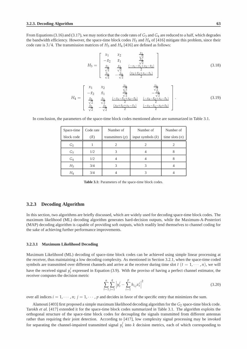
3.2.3. Decoding Algorithm 63
From Equations (3.16) and (3.17), we may notice that the coderates ofG3 andG4 are reduced to a half, which degradesthe bandwidth efficiency. However, the space-time block codesH3 andH4 of [416] mitigate this problem, since theircode rate is3/4. The transmission matrices ofH3 andH4 [416] are defined as follows:
H3 =
x1 x2x3√
2−x2 x1
x3√2
x3√2
x3√2
(−x1−x1+x2−x2)2
x3√2
− x3√2
(x2+x2+x1−x1)2
(3.18)
H4 =
x1 x2x3√
2
x3√2
−x2 x1x3√
2− x3√
2x3√
2
x3√2
(−x1−x1+x2−x2)2
(−x2−x2+x1−x1)2
x3√2
− x3√2
(x2+x2+x1−x1)2
(−x1−x1−x2+x2)2
. (3.19)
In conclusion, the parameters of the space-time block codesmentioned above are summarized in Table 3.1.
Space-time Code rate Number of Number of Number of
block code (R) transmitters (p) input symbols (k) time slots (n)
G2 1 2 2 2
G3 1/2 3 4 8
G4 1/2 4 4 8
H3 3/4 3 3 4
H4 3/4 4 3 4
Table 3.1: Parameters of the space-time block codes.
3.2.3 Decoding Algorithm
In this section, two algorithms are briefly discussed, whichare widely used for decoding space-time block codes. Themaximum likelihood (ML) decoding algorithm generates hard-decision outputs, while the Maximum-A-Posteriori(MAP) decoding algorithm is capable of providing soft outputs, which readily lend themselves to channel coding forthe sake of achieving further performance improvements.
3.2.3.1 Maximum Likelihood Decoding
Maximum Likelihood (ML) decoding of space-time block codescan be achieved using simple linear processing atthe receiver, thus maintaining a low decoding complexity. As mentioned in Section 3.2.1, when the space-time codedsymbols are transmitted over different channels and arriveat the receiver during time slott (t = 1, · · · , n), we will
have the received signalyjt expressed in Equation (3.9). With the proviso of having a perfect channel estimator, the
receiver computes the decision metricn
∑t=1
q
∑j=1
∣
∣
∣y
jt −
p
∑i=1
hi,jxit
∣
∣
∣
2(3.20)
over all indicesi = 1, · · · , n; j = 1, · · · , p and decides in favor of the specific entry that minimizes the sum.
Alamouti [403] first proposed a simple maximum likelihood decoding algorithm for theG2 space-time block code.Tarokhet al. [417] extended it for the space-time block codes summarizedin Table 3.1. The algorithm exploits theorthogonal structure of the space-time block codes for decoupling the signals transmitted from different antennasrather than requiring their joint detection. According to [417], low complexity signal processing may be invoked
for separating the channel-impaired transmitted signalyjt into k decision metrics, each of which corresponding to

64 Chapter3. Channel Coding Assisted STBC-OFDM Systems
the channel-impaired version of a specific information symbol of the setxi, i = 1, · · · , k. For example, for theG2
space-time block code, we will minimize the decision metric
∣
∣
∣
∣
∣
[
q
∑j=1
(
yj1h1,j + y
j2h2,j
)
]
− x1
∣
∣
∣
∣
∣
2
+
(
q
∑j=1
2
∑i=1
∣
∣hi,j
∣
∣
2 − 1
)
|x1|2 (3.21)
for decodingx1 and the decision metric
∣
∣
∣
∣
∣
[
q
∑j=1
(
yj1h2,j − y
j2h1,j
)
]
− x2
∣
∣
∣
∣
∣
2
+
(
q
∑j=1
2
∑i=1
∣
∣hi,j
∣
∣
2 − 1
)
|x2|2 (3.22)
for decodingx2. The relevant decision metrics for decoding other STBC codes can be found in [417].
3.2.3.2 Maximum-A-Posteriori Decoding
As seen in Equations (3.21) and (3.22), hard decisions wouldhave to be made in order to generate the decodedoutputs, which are the most likely transmitted informationsymbols. In other words, the usual ML detection is ahard-decoding method. However, in most practical systems various channel codes, such as Low Density Parity Check(LDPC) codes [422] or turbo codes [359,423,424], may have tobe combined with STBC codes for the sake of furtherimproving the system’s performance. In this case, the space-time decoder must provide soft outputs, which can beefficiently utilized by the channel decoder.
Bauch [425] presented a simple symbol-by-symbol Maximum-A-Posteriori (MAP) algorithm for decoding space-time block codes. According to [425], the aposteriori probability of each information symbolxi (i = 1, · · · , k)is:
ln P(
xi
∣
∣y1, y2, · · · , yq)
= const + ln P(
y1, y2, · · · , yq |xi
)
+ ln P (xi) , (3.23)
whereyj = [ yj1, y
j2, · · · , y
jn ] (j = 1, · · · , q) represents the received signal vector at receiverj during the period
spanning from time slot 1 to time slotn. For example, for the space-time block codeG2 (k = 2, n = 2) the aposterioriprobabilities are:
ln P(
x1
∣
∣y1, y2, · · · , yq)
= const +
− 1
2σ2
∣
∣
∣
∣
∣
[
q
∑j=1
(
yj1h1,j + y
j2h2,j
)
]
− x1
∣
∣
∣
∣
∣
2
+
(
q
∑j=1
2
∑i=1
∣
∣hi,j
∣
∣
2 − 1
)
|x1|2
+ ln P (x1)
(3.24)
ln P(
x2
∣
∣y1, y2, · · · , yq)
= const +
− 1
2σ2
∣
∣
∣
∣
∣
[
q
∑j=1
(
yj1h2,j − y
j2h1,j
)
]
− x2
∣
∣
∣
∣
∣
2
+
(
q
∑j=1
2
∑i=1
∣
∣hi,j
∣
∣
2 − 1
)
|x2|2
+ ln P (x2) .
(3.25)
We notice that Equations (3.24) and (3.25) are quite similarto Equations (3.21) and (3.22), respectively. In fact, it canbe shown that Bauch’s MAP algorithms can be extended for decoding other space-time block codes, such as theG3,G4, H3 andH4 and the corresponding algorithms also resemble the ML algorithms [359] discussed in Section 3.2.3.1.Given the aposteriori probabilities of the symbols, we can derive the corresponding aposteriori probabilities of thebits (i.e. the corresponding soft outputs) using the symbol-to-bit probability conversion of:
P (di = 0) = ∑j
P(
xj
∣
∣y1, y2, · · · , yq
)
, ∀xj = (d1 · · · di · · · db) , di = 0, (3.26)
P (di = 1) = ∑j
P(
xj
∣
∣y1, y2, · · · , yq
)
, ∀xj = (d1 · · · di · · · db) , di = 1, (3.27)
whereP(di = 0) or P(di = 1) represents the probability of theith bit, namelydi, of theb-bit symbol being zero andone, respectively. Let us consider the QPSK modulation scheme for example. The phasor constellation of QPSK isshown in Figure 3.2:
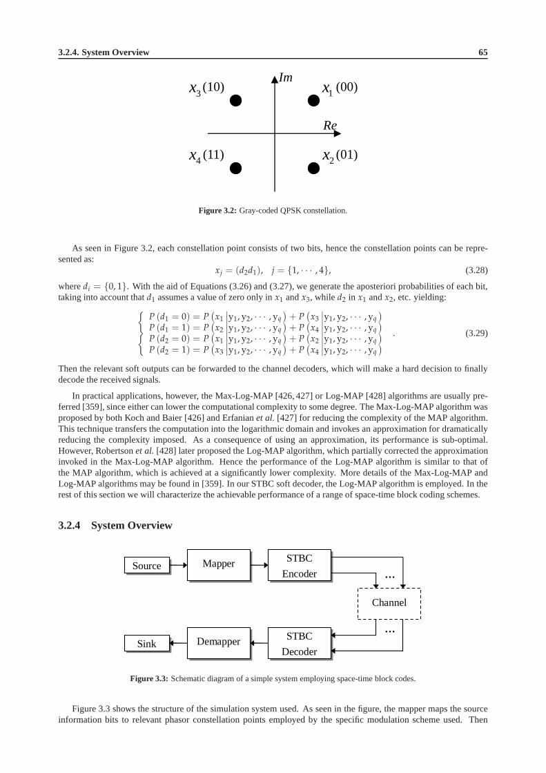
3.2.4. System Overview 65
(00)
Re
Im 1x3x
2x4x (01)
(10)
(11)
Figure 3.2: Gray-coded QPSK constellation.
As seen in Figure 3.2, each constellation point consists of two bits, hence the constellation points can be repre-sented as:
xj = (d2d1), j = 1, · · · , 4, (3.28)
wheredi = 0, 1. With the aid of Equations (3.26) and (3.27), we generate theaposteriori probabilities of each bit,taking into account thatd1 assumes a value of zero only inx1 andx3, while d2 in x1 andx2, etc. yielding:
P (d1 = 0) = P(
x1
∣
∣y1, y2, · · · , yq
)
+ P(
x3
∣
∣y1, y2, · · · , yq
)
P (d1 = 1) = P(
x2
∣
∣y1, y2, · · · , yq)
+ P(
x4
∣
∣y1, y2, · · · , yq)
P (d2 = 0) = P(
x1
∣
∣y1, y2, · · · , yq)
+ P(
x2
∣
∣y1, y2, · · · , yq)
P (d2 = 1) = P(
x3
∣
∣y1, y2, · · · , yq)
+ P(
x4
∣
∣y1, y2, · · · , yq)
. (3.29)
Then the relevant soft outputs can be forwarded to the channel decoders, which will make a hard decision to finallydecode the received signals.
In practical applications, however, the Max-Log-MAP [426,427] or Log-MAP [428] algorithms are usually pre-ferred [359], since either can lower the computational complexity to some degree. The Max-Log-MAP algorithm wasproposed by both Koch and Baier [426] and Erfanianet al. [427] for reducing the complexity of the MAP algorithm.This technique transfers the computation into the logarithmic domain and invokes an approximation for dramaticallyreducing the complexity imposed. As a consequence of using an approximation, its performance is sub-optimal.However, Robertsonet al. [428] later proposed the Log-MAP algorithm, which partially corrected the approximationinvoked in the Max-Log-MAP algorithm. Hence the performance of the Log-MAP algorithm is similar to that ofthe MAP algorithm, which is achieved at a significantly lowercomplexity. More details of the Max-Log-MAP andLog-MAP algorithms may be found in [359]. In our STBC soft decoder, the Log-MAP algorithm is employed. In therest of this section we will characterize the achievable performance of a range of space-time block coding schemes.
3.2.4 System Overview
Source
Sink
Mapper STBC
Encoder
Channel
Demapper STBC
Decoder
…
…
Figure 3.3: Schematic diagram of a simple system employing space-time block codes.
Figure 3.3 shows the structure of the simulation system used. As seen in the figure, the mapper maps the sourceinformation bits to relevant phasor constellation points employed by the specific modulation scheme used. Then

66 Chapter3. Channel Coding Assisted STBC-OFDM Systems
the symbols are forwarded to the space-time encoder. The encoded symbols are then transmitted through differentantennas and arrive the receiver(s), where the received signals will be decoded by the space-time decoder. Finally,the demapper converts the STBC-decoded symbols back to the information bits and the Bit Error Ratio (BER) iscalculated. The parameters of all the space-time block codes studied are summarized in Table 3.1. There followingassumptions were used:
• Signals are transmitted over uncorrelated Rayleigh fadingchannels;
• The channels are quasi-static so that the path gains are constant acrossn consecutive time slots, correspondingto then rows of the space-time block codes’ transmission matrix;
• The average signal power received from each transmitter antenna is the same;
• The receiver has a perfect knowledge of the channels’ fadingamplitudes.
These assumptions simplify the simulations to a degree, therefore the system concerned is not a realistic one. However,since the experimental circumstances are identical for allperformance comparisons, the results characterize the relativeperformance of various space-time block codes.
3.2.5 Simulation Results
In the past sections, the basic principles of space-time block codes as well as the simulation conditions were presented.In this section, our simulation results will be provided forthe sake of comparatively studying the performance of thevarious STBCs of Table 3.1.
3.2.5.1 Performance over Uncorrelated Rayleigh Fading Channels
stbc_rx1_1bps.gle Mon Jun 30 2003 20:34:07
0 2 4 6 8 10 12 14 16 18 20 22 24 26 28 30Eb/N0 (dB)
10-5
10-4
10-3
10-2
10-1
100
BE
R
1RX, 1BPS, Uncorrelated
G4 (4Tx, 1Rx), QPSKG3 (3Tx, 1Rx), QPSKG2 (2Tx, 1Rx), BPSK(1Tx, 1Rx), BPSK
Figure 3.4: The BER versusEb/N0 performance of theG2, G3, andG4 space-time block codes of Table 3.1 at aneffective throughput of1 BPSusingone receiveroveruncorrelated Rayleigh fading channels.
Performance at the Throughput of 1 BPS Figure 3.4 compares the performance of theG2, G3, andG4 space-time block codes in conjunction with one receiver at the throughput of 1 BPS over the uncorrelated Rayleigh fadingchannel. Binary Phase-Shift Keying (BPSK) modulation is employed in conjunction with the space-time codeG2,while QPSK modulation is considered with the half-rate space-time codesG3 andG4 so that the system throughputremains 1 BPS. From Figure 3.4 we can see that at the BER of10−5 theG3 andG4 codes provide an approximately5.5 and 7.5 dB gain over theG2 code, respectively. If we add one more receiver in the context of all of these schemes,

3.2.5. Simulation Results 67
stbc_rx2_1bps.gle Mon Jun 30 2003 20:35:05
0 2 4 6 8 10 12 14 16 18 20 22 24 26 28 30Eb/N0 (dB)
10-5
10-4
10-3
10-2
10-1
100
BE
R
2RX, 1BPS, Uncorrelated
G4 (4Tx, 2Rx), QPSKG3 (3Tx, 2Rx), QPSKG2 (2Tx, 2Rx), BPSK(1Tx, 1Rx), BPSK
Figure 3.5: The BER versusEb/N0 performance of theG2, G3, andG4 space-time block codes of Table 3.1 at aneffective throughput of1 BPSusingtwo receiversoveruncorrelated Rayleigh fading channels.
as seen in Figure 3.5, the relevantEb/N0 gain of theG3 andG4 schemes over theG2 arrangement reduces to 2.5and 3.5 dB, respectively. This may suggest that theG2 code using two receivers has achieved most of the attainablediversity gain [359], and hence even if we further increase the number of transmitter antennas, the performance cannotbe significantly improved.
Performance at the Throughput of 2 BPS In Figure 3.6 the performances of the space-time block codesusingone receiver and having a throughput of about 2 BPS over uncorrelated Rayleigh fading channels are compared. Inorder to meet the 2 BPS throughput criteria, QPSK modulationis used for theG2 code, while 16QAM modulation isemployed for theG3 andG4 arrangements, as the latter ones are half rate codes. However, for the 3
4 -rate codesH3
andH4, an exact throughput of 2 BPS cannot be achieved. Thus we chose 8PSK and the throughput of theH3 andH4
schemes became 2.25 BPS, which is close to 2 BPS.
From Figure 3.6 we can see that when the Signal-to-Noise Ratio (SNR) is low, i.e.Eb/N0 is below 12.5 dB, thespace-time block codeG2 performs better than other codes, although the performancedifference is not significant.When Eb/N0 increases to a value higher than 12.5 dB, however, theG4 code outperforms other codes, having anapproximately 1 dB gain over theH4 code at the BER of10−5. Similarly, theG3 code achieves an approximately 1dB gain over theH3 code at the BER of10−5. We may note that although theG3 andG4 codes employ a higher-order 16QAM modulation scheme, which is more vulnerable to channel effects than the lower-order 8PSK modulationscheme used by theH3 andH4 codes, the former performs slightly better than the latter.
In the scenario of using two receivers, however, theG2 code stands out in comparison to all the candidates, asFigure 3.7 indicates. This result suggests that the attainable diversity gain has already been achieved by theG2 codeusing two receivers. Furthermore, the potential benefit of using more transmitters is eroded by the employment ofhigher throughput, but more vulnerable modulation schemes, which are more prone to transmission errors.
Performance at the Throughput of 3 BPS The performances of the space-time block codes using one receiverand having a throughput of 3 BPS over uncorrelated Rayleigh fading channels are compared in Figure 3.8. Again, sim-ilarly to the scenario of having a throughput of 2 BPS, theG2 code performs best at a low SNR, namely below about 10dB, although the performance difference betweenG2 and other codes is even smaller than it is in Figure 3.6. As shownin Figure3.8, at the BER of10−5, the H3 andH4 codes achieve a gain of about 3 dB over theG3 andG4 codes, re-spectively. Since the space-time block codes themselves donot have an error-correction capability which would allowthem to correct the extra errors induced by employing a more vulnerable, higher-order modulation scheme [359], thisresults in a poorer performance. Furthermore, since the relative increase of the constellation density when changingfrom 16QAM to 64QAM is higher than that from 8PSK to 16QAM, theperformance degradation imposed by revertingfrom 16QAM to 64QAM is more severe than that imposed by optingfor 16QAM instead of 8PSK. Therefore it is not

68 Chapter3. Channel Coding Assisted STBC-OFDM Systems
stbc_rx1_2bps.gle Mon Jun 30 2003 20:35:52
0 2 4 6 8 10 12 14 16 18 20 22 24 26 28 30Eb/N0 (dB)
10-5
10-4
10-3
10-2
10-1
100
BE
R1RX, 2BPS, Uncorrelated
H4 (4Tx, 1Rx), 8PSKH3 (3Tx, 1Rx), 8PSKG4 (4Tx, 1Rx), 16QAMG3 (3Tx, 1Rx), 16QAMG2 (2Tx, 1Rx), QPSK(1Tx, 1Rx), QPSK
Figure 3.6: The BER versusEb/N0 performance of theG2, G3, G4, H3, andH4 space-time block codes of Table 3.1at an effective throughput of about2 BPSusingone receiveroveruncorrelated Rayleigh fading channels.
stbc_rx2_2bps.gle Mon Jun 30 2003 20:36:32
0 2 4 6 8 10 12 14 16 18 20 22 24 26 28 30Eb/N0 (dB)
10-5
10-4
10-3
10-2
10-1
100
BE
R
2RX, 2BPS, Uncorrelated
H4 (4Tx, 2Rx), 8PSKH3 (3Tx, 2Rx), 8PSKG4 (4Tx, 2Rx), 16QAMG3 (3Tx, 2Rx), 16QAMG2 (2Tx, 2Rx), QPSK(1Tx, 1Rx), QPSK
Figure 3.7: The BER versusEb/N0 performance of theG2, G3, G4, H3, andH4 space-time block codes of Table 3.1at an effective throughput of about2 BPSusingtwo receiversoveruncorrelated Rayleigh fading channels.
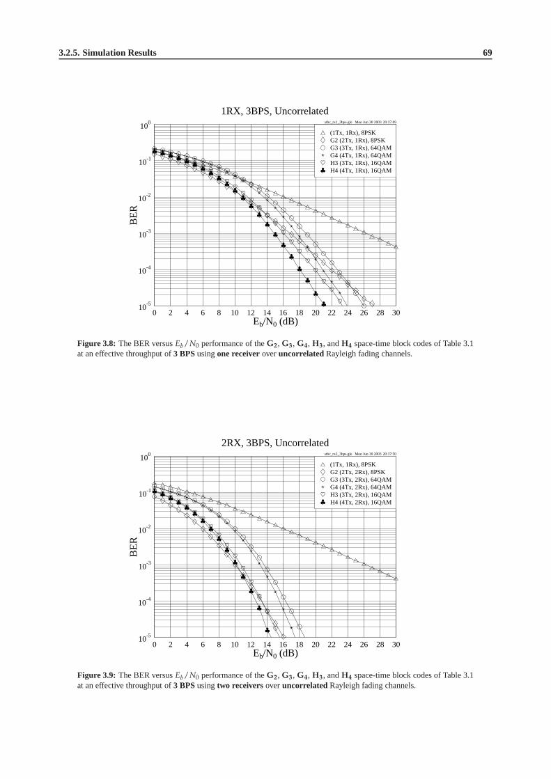
3.2.5. Simulation Results 69
stbc_rx1_3bps.gle Mon Jun 30 2003 20:37:09
0 2 4 6 8 10 12 14 16 18 20 22 24 26 28 30Eb/N0 (dB)
10-5
10-4
10-3
10-2
10-1
100
BE
R
1RX, 3BPS, Uncorrelated
H4 (4Tx, 1Rx), 16QAMH3 (3Tx, 1Rx), 16QAMG4 (4Tx, 1Rx), 64QAMG3 (3Tx, 1Rx), 64QAMG2 (2Tx, 1Rx), 8PSK(1Tx, 1Rx), 8PSK
Figure 3.8: The BER versusEb/N0 performance of theG2, G3, G4, H3, andH4 space-time block codes of Table 3.1at an effective throughput of3 BPSusingone receiveroveruncorrelated Rayleigh fading channels.
stbc_rx2_3bps.gle Mon Jun 30 2003 20:37:50
0 2 4 6 8 10 12 14 16 18 20 22 24 26 28 30Eb/N0 (dB)
10-5
10-4
10-3
10-2
10-1
100
BE
R
2RX, 3BPS, Uncorrelated
H4 (4Tx, 2Rx), 16QAMH3 (3Tx, 2Rx), 16QAMG4 (4Tx, 2Rx), 64QAMG3 (3Tx, 2Rx), 64QAMG2 (2Tx, 2Rx), 8PSK(1Tx, 1Rx), 8PSK
Figure 3.9: The BER versusEb/N0 performance of theG2, G3, G4, H3, andH4 space-time block codes of Table 3.1at an effective throughput of3 BPSusingtwo receiversoveruncorrelated Rayleigh fading channels.
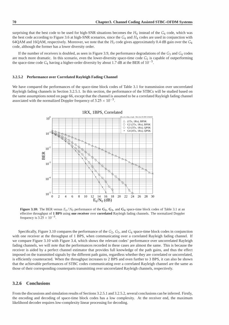
70 Chapter3. Channel Coding Assisted STBC-OFDM Systems
surprising that the best code to be used for high-SNR situations becomes theH4 instead of theG4 code, which wasthe best code according to Figure 3.6 at high-SNR scenarios,since theG4 andH4 codes are used in conjunction with64QAM and 16QAM, respectively. Moreover, we note that theH3 code gives approximately 0.4 dB gain over theG4
code, although the former has a lower diversity order.
If the number of receivers is doubled, as seen in Figure 3.9, the performance degradations of theG3 andG4 codesare much more dramatic. In this scenario, even the lower-diversity space-time codeG2 is capable of outperformingthe space-time codeG4 having a higher-order diversity by about 1.7 dB at the BER of10−5.
3.2.5.2 Performance over Correlated Rayleigh Fading Channel
We have compared the performances of the space-time block codes of Table 3.1 for transmission over uncorrelatedRayleigh fading channels in Section 3.2.5.1. In this section, the performance of the STBCs will be studied based onthe same assumptions noted on page 66, except that the channel is assumed to be a correlated Rayleigh fading channelassociated with the normalized Doppler frequency of3.25 × 10−5.
stbc_rx1_1bps_cor.gle Mon Jun 30 2003 20:46:02
0 2 4 6 8 10 12 14 16 18 20 22 24 26 28 30Eb/N0 (dB)
10-5
10-4
10-3
10-2
10-1
100
BE
R
1RX, 1BPS, Correlated
G4 (4Tx, 1Rx), QPSKG3 (3Tx, 1Rx), QPSKG2 (2Tx, 1Rx), BPSK(1Tx, 1Rx), BPSK
Figure 3.10: The BER versusEb/N0 performance of theG2, G3, andG4 space-time block codes of Table 3.1 at aneffective throughput of1 BPSusingone receiverovercorrelated Rayleigh fading channels. The normalized Dopplerfrequency is3.25 × 10−5.
Specifically, Figure 3.10 compares the performance of theG2, G3, andG4 space-time block codes in conjunctionwith one receiver at the throughput of 1 BPS, when communicating over a correlated Rayleigh fading channel. Ifwe compare Figure 3.10 with Figure 3.4, which shows the relevant codes’ performance over uncorrelated Rayleighfading channels, we will note that the performances recorded in these cases are almost the same. This is because thereceiver is aided by a perfect channel estimator that provides full knowledge of the path gains, and thus the effectimposed on the transmitted signals by the different path gains, regardless whether they are correlated or uncorrelated,is efficiently counteracted. When the throughput increasesto 2 BPS and even further to 3 BPS, it can also be shownthat the achievable performances of STBC codes communicating over a correlated Rayleigh channel are the same asthose of their corresponding counterparts transmitting over uncorrelated Rayleigh channels, respectively.
3.2.6 Conclusions
From the discussions and simulation results of Sections 3.2.5.1 and 3.2.5.2, several conclusions can be inferred. Firstly,the encoding and decoding of space-time block codes has a lowcomplexity. At the receiver end, the maximumlikelihood decoder requires low-complexity linear processing for decoding.

3.3. Channel Coded Space-Time Block Codes 71
Secondly, from Figures 3.4, 3.6 and 3.8 we note that when the effective throughput is increased, the phasor-constellation has to be extended for accommodating the increased number of bits. Hence the performances of thehalf-rate codesG3 andG4 degrade in comparison to that of the unity-rate codeG2.
Thirdly, at the even higher effective throughput of 3 BPS, the H3 andH4 codes perform better than theG3 andG4
codes, respectively, as shown in Figure 3.8. Moreover, according to Figures 3.4, 3.5, 3.8 and 3.9, when the number ofreceivers is increased, the performance gain of theG3, G4, H3 andH4 codes over theG2 code becomes more modestbecause much of the attainable diversity gain has already been achieved using theG2 code employing two receivers.
Last but not least, it was also found that the performances ofthe space-time codes communicating over uncorrelatedand correlated Rayleigh fading channels are similar, provided that the effective throughput is the same.
The achievable coding gains of the space-time block codes are summarized in Table 3.2. The coding gain is definedas theEb/N0 difference, expressed in terms of decibels, at a BER of10−5 between the various space-time block codedand uncoded single-transmitter systems having the same throughput. The best schemes at the effective throughput of1, 2, and 3 BPS are printed in bold, respectively.
Eb/N0 (dB) Gain (dB)
BPS Code Code Modem BER
Rate 10−3 10−5 10−3 10−5
Uncoded 1 BPSK 24.22 44.00 0.00 0.00
1.00 G2 1 BPSK 14.08 24.22 10.14 19.78
G3 1/2 QPSK 11.33 18.71 12.89 25.29
G4 1/2 QPSK 10.10 15.85 14.12 28.15
Uncoded 1 QPSK 24.22 44.00 0.00 0.00
G2 1 QPSK 14.12 24.22 10.10 19.78
2.00 G3 1/2 16QAM 14.78 22.06 9.44 21.94
G4 1/2 16QAM 13.61 19.58 10.61 24.42
2.25 H3 3/4 8PSK 15.43 23.00 8.79 21.00
≈ 2.00 H4 3/4 8PSK 14.31 20.48 9.91 23.52
Uncoded 1 8PSK 26.30 46.26 0.00 0.00
G2 1 8PSK 16.80 27.21 9.50 19.05
3.00 G3 1/2 64QAM 18.83 26.00 7.47 20.26
G4 1/2 64QAM 17.69 23.92 8.61 22.34
H3 3/4 16QAM 16.06 23.36 10.24 22.90
H4 3/4 16QAM 14.87 21.10 11.43 25.16
Table 3.2: Coding gains of the space-time block codes using one receiver when communicating over uncorrelated and
correlated Rayleigh fading channels. The performance of the best scheme for a specific effective throughput is printed
in bold.
3.3 Channel Coded Space-Time Block Codes
In Section 3.2, we have presented the basic concepts of the space-time block codes and provided a range of character-istic performance results. Furthermore, the MAP algorithminvoked for decoding STBC codes has also been brieflyhighlighted. This enables a space-time decoder to provide soft outputs that can be exploited by concatenated channeldecoders for further improving the system’s performance. In this section, we will concatenate the space-time blockcodes with various Low Density Parity Check (LDPC) channel codes [422] and with a Turbo Convolutional (TC)code [423,424]. The performances of the different schemes will also be evaluated.

72 Chapter3. Channel Coding Assisted STBC-OFDM Systems
3.3.1 Space-Time Block Codes with LDPC Channel Codes
LDPC codes were devised by Gallager [422] in 1962. During theearly evolutionary phase of channel coding, LDPCschemes made a limited impact on the research of the channel coding community, although they showed an un-precedented performance prior to the turbo coding era. Thiswas because LDPC codes required a relatively highstorage space and complexity. However, owing to their capability of approaching Shannon’s predicted performancelimits [429], research interests in LDPC codes have been rekindled during recent years [429–433].
LDPC codes [422] belong to the family of linear block codes, which are defined by a parity check matrix havingM rows andN columns. The column weightj and row weightk is typically significantly lower than the dimensionM andN of the parity check matrix. The construction of the parity check matrix is referred to as regular or irregular,depending on whether the Hamming weight per column or row is identical. Reference [431] shows that carefullydesigned irregular LDPC codes may perform better than theirregular counterparts. Furthermore, when the blocklength is increased, irregular LDPC codes may become capable of outperforming turbo codes [429] at the cost of ahigher complexity. Since the details of the decoding of LDPCcodes can be found in [434], in the forthcoming sectionswe are more interested in the performance of LDPC codes than the LDPC decoding algorithm itself.
ldpc.gle Mon Jun 30 2003 21:26:21
0 2 4 6 8 10 12 14 16 18 20Eb/N0 (dB)
10-5
10-4
10-3
10-2
10-1
100
BE
R
Performance of LDPC Codes
LDPC(R=2/3),8PSK,CorrelatedLDPC(R=2/3),8PSK,UncorrelatedLDPC(R=1/2),QPSK,CorrelatedLDPC(R=1/2),QPSK,Uncorrelated
Figure 3.11: The BER versusEb/N0 performance of several LDPC codes communicating over both uncorrelated andcorrelated Rayleigh fading channels. The parameters of theLDPC codes are given in Tables 3.3 and 3.4. The normalizedDoppler frequency of the correlated Rayleigh fading channels was3.25 × 10−5. The effective throughput of the QPSKand 8PSK schemes were 1 BPS and 2 BPS, respectively.
The number of columnsN is given by the number of coded bits hosted by a LDPC codeword,while the number ofrowsM corresponds to the number of parity check constraints imposed by the design of the LDPC code. The numberof information bits encoded by a LDPC codeword is denoted byK = N − M, yielding a coding rate ofK/M [434].Thus, the LDPC code rate can be adjusted by changingK and/orM.
Figure 3.11 characterizes the performance of several LDPC codes for transmission over both uncorrelated andcorrelated Rayleigh fading channels. The normalized Doppler frequency of the correlated Rayleigh channel was3.25 × 10−5. It was found that the LDPC codes perform far better over uncorrelated than over correlated Rayleighchannels, since the codeword length is short. This characteristic predetermines the expected performance of theLDPC-STBC coded concatenated system to be introduced in thenext section and characterized in Section 3.3.1.2.2.
3.3.1.1 System Overview
Figure 3.12 shows the schematic diagram of the system. The source bits are first encoded by the LDPC encoder, whoseoutputs are modulated and forwarded to the STBC encoder. At the receiver, the noise-contaminated received symbolsare decoded by the STBC soft decoder. As discussed in Section3.2.3.2, the soft outputs constituted by the aposteriori
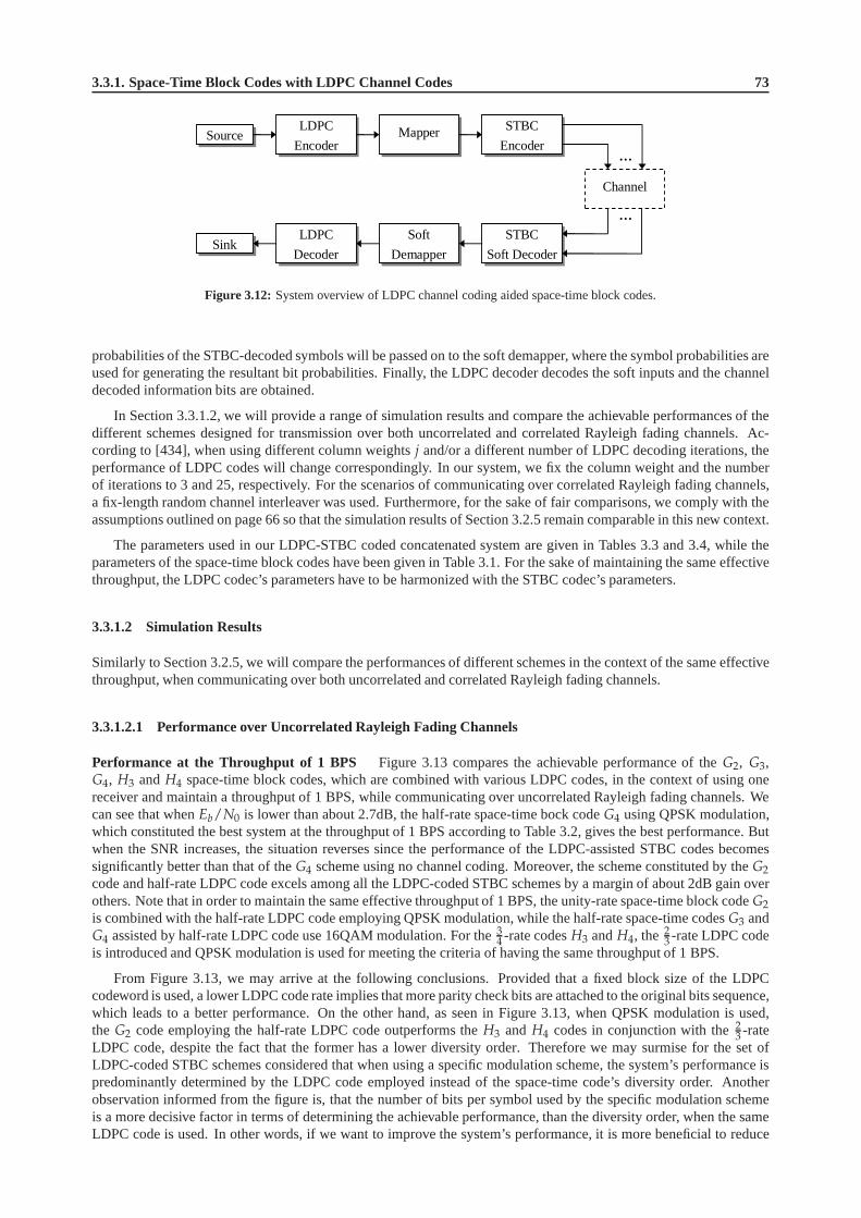
3.3.1. Space-Time Block Codes with LDPC Channel Codes 73
Source
Sink
LDPC
Encoder Mapper STBC
Encoder
Channel
LDPC
Decoder
Soft
Demapper
STBC
Soft Decoder
…
…
Figure 3.12: System overview of LDPC channel coding aided space-time block codes.
probabilities of the STBC-decoded symbols will be passed onto the soft demapper, where the symbol probabilities areused for generating the resultant bit probabilities. Finally, the LDPC decoder decodes the soft inputs and the channeldecoded information bits are obtained.
In Section 3.3.1.2, we will provide a range of simulation results and compare the achievable performances of thedifferent schemes designed for transmission over both uncorrelated and correlated Rayleigh fading channels. Ac-cording to [434], when using different column weightsj and/or a different number of LDPC decoding iterations, theperformance of LDPC codes will change correspondingly. In our system, we fix the column weight and the numberof iterations to 3 and 25, respectively. For the scenarios ofcommunicating over correlated Rayleigh fading channels,a fix-length random channel interleaver was used. Furthermore, for the sake of fair comparisons, we comply with theassumptions outlined on page 66 so that the simulation results of Section 3.2.5 remain comparable in this new context.
The parameters used in our LDPC-STBC coded concatenated system are given in Tables 3.3 and 3.4, while theparameters of the space-time block codes have been given in Table 3.1. For the sake of maintaining the same effectivethroughput, the LDPC codec’s parameters have to be harmonized with the STBC codec’s parameters.
3.3.1.2 Simulation Results
Similarly to Section 3.2.5, we will compare the performances of different schemes in the context of the same effectivethroughput, when communicating over both uncorrelated andcorrelated Rayleigh fading channels.
3.3.1.2.1 Performance over Uncorrelated Rayleigh Fading Channels
Performance at the Throughput of 1 BPS Figure 3.13 compares the achievable performance of theG2, G3,G4, H3 andH4 space-time block codes, which are combined with various LDPC codes, in the context of using onereceiver and maintain a throughput of 1 BPS, while communicating over uncorrelated Rayleigh fading channels. Wecan see that whenEb/N0 is lower than about 2.7dB, the half-rate space-time bock code G4 using QPSK modulation,which constituted the best system at the throughput of 1 BPS according to Table 3.2, gives the best performance. Butwhen the SNR increases, the situation reverses since the performance of the LDPC-assisted STBC codes becomessignificantly better than that of theG4 scheme using no channel coding. Moreover, the scheme constituted by theG2
code and half-rate LDPC code excels among all the LDPC-codedSTBC schemes by a margin of about 2dB gain overothers. Note that in order to maintain the same effective throughput of 1 BPS, the unity-rate space-time block codeG2
is combined with the half-rate LDPC code employing QPSK modulation, while the half-rate space-time codesG3 andG4 assisted by half-rate LDPC code use 16QAM modulation. For the 3
4 -rate codesH3 andH4, the 23 -rate LDPC code
is introduced and QPSK modulation is used for meeting the criteria of having the same throughput of 1 BPS.
From Figure 3.13, we may arrive at the following conclusions. Provided that a fixed block size of the LDPCcodeword is used, a lower LDPC code rate implies that more parity check bits are attached to the original bits sequence,which leads to a better performance. On the other hand, as seen in Figure 3.13, when QPSK modulation is used,the G2 code employing the half-rate LDPC code outperforms theH3 and H4 codes in conjunction with the23 -rateLDPC code, despite the fact that the former has a lower diversity order. Therefore we may surmise for the set ofLDPC-coded STBC schemes considered that when using a specific modulation scheme, the system’s performance ispredominantly determined by the LDPC code employed insteadof the space-time code’s diversity order. Anotherobservation informed from the figure is, that the number of bits per symbol used by the specific modulation schemeis a more decisive factor in terms of determining the achievable performance, than the diversity order, when the sameLDPC code is used. In other words, if we want to improve the system’s performance, it is more beneficial to reduce
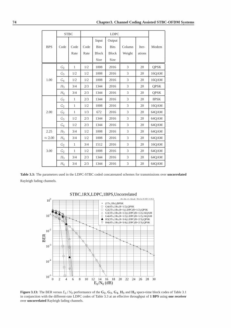
74 Chapter3. Channel Coding Assisted STBC-OFDM Systems
STBC LDPC
Input Output
BPS Code Code Code Bits Bits Column Iter- Modem
Rate Rate Block Block Weight ations
Size Size
G2 1 1/2 1008 2016 3 20 QPSK
G3 1/2 1/2 1008 2016 3 20 16QAM
1.00 G4 1/2 1/2 1008 2016 3 20 16QAM
H3 3/4 2/3 1344 2016 3 20 QPSK
H4 3/4 2/3 1344 2016 3 20 QPSK
G2 1 2/3 1344 2016 3 20 8PSK
G2 1 1/2 1008 2016 3 20 16QAM
2.00 G2 1 1/3 672 2016 3 20 64QAM
G3 1/2 2/3 1344 2016 3 20 64QAM
G4 1/2 2/3 1344 2016 3 20 64QAM
2.25 H3 3/4 1/2 1008 2016 3 20 64QAM
≈ 2.00 H4 3/4 1/2 1008 2016 3 20 64QAM
G2 1 3/4 1512 2016 3 20 16QAM
3.00 G2 1 1/2 1008 2016 3 20 64QAM
H3 3/4 2/3 1344 2016 3 20 64QAM
H4 3/4 2/3 1344 2016 3 20 64QAM
Table 3.3: The parameters used in the LDPC-STBC coded concatenated schemes for transmissions overuncorrelated
Rayleigh fading channels.
stbc_ldpc_rx1_1bps.gle Mon Jun 30 2003 21:30:22
0 2 4 6 8 10 12 14 16 18 20 22 24 26 28 30Eb/N0 (dB)
10-5
10-4
10-3
10-2
10-1
100
BE
R
STBC,1RX,LDPC,1BPS,Uncorrelated
H4(4Tx,1Rx,R=3/4),LDPC(R=2/3),QPSKH3(3Tx,1Rx,R=3/4),LDPC(R=2/3),QPSKG4(4Tx,1Rx,R=1/2),LDPC(R=1/2),16QAMG3(3Tx,1Rx,R=1/2),LDPC(R=1/2),16QAMG2(2Tx,1Rx,R=1),LDPC(R=1/2),QPSKG4(4Tx,1Rx,R=1/2),QPSK(1Tx,1Rx),BPSK
Figure 3.13: The BER versusEb/N0 performance of theG2, G3, G4, H3 andH4 space-time block codes of Table 3.1in conjunction with the different-rate LDPC codes of Table 3.3 at an effective throughput of1 BPSusingone receiveroveruncorrelated Rayleigh fading channels.
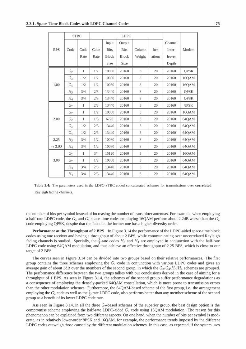
3.3.1. Space-Time Block Codes with LDPC Channel Codes 75
STBC LDPC
Input Output Channel
BPS Code Code Code Bits Bits Column Iter- Inter- Modem
Rate Rate Block Block Weight ations leaver
Size Size Depth
G2 1 1/2 10080 20160 3 20 20160 QPSK
G3 1/2 1/2 10080 20160 3 20 20160 16QAM
1.00 G4 1/2 1/2 10080 20160 3 20 20160 16QAM
H3 3/4 2/3 13440 20160 3 20 20160 QPSK
H4 3/4 2/3 13440 20160 3 20 20160 QPSK
G2 1 2/3 13440 20160 3 20 20160 8PSK
G2 1 1/2 10080 20160 3 20 20160 16QAM
2.00 G2 1 1/3 6720 20160 3 20 20160 64QAM
G3 1/2 2/3 13440 20160 3 20 20160 64QAM
G4 1/2 2/3 13440 20160 3 20 20160 64QAM
2.25 H3 3/4 1/2 10080 20160 3 20 20160 64QAM
≈ 2.00 H4 3/4 1/2 10080 20160 3 20 20160 64QAM
G2 1 3/4 15120 20160 3 20 20160 16QAM
3.00 G2 1 1/2 10080 20160 3 20 20160 64QAM
H3 3/4 2/3 13440 20160 3 20 20160 64QAM
H4 3/4 2/3 13440 20160 3 20 20160 64QAM
Table 3.4: The parameters used in the LDPC-STBC coded concatenated schemes for transmissions overcorrelated
Rayleigh fading channels.
the number of bits per symbol instead of increasing the number of transmitter antennas. For example, when employinga half-rate LDPC code, theG3 andG4 space-time codes employing 16QAM perform about 2.2dB worsethan theG2
code employing QPSK, despite that the fact that the former one has a higher diversity order.
Performance at the Throughput of 2 BPS In Figure 3.14 the performance of the LDPC-aided space-timeblockcodes using one receiver and having a throughput of about 2 BPS, while communicating over uncorrelated Rayleighfading channels is studied. Specially, the3
4 -rate codesH3 and H4 are employed in conjunction with the half-rateLDPC code using 64QAM modulation, and thus achieve an effective throughput of 2.25 BPS, which is close to ourtarget of 2 BPS.
The curves seen in Figure 3.14 can be divided into two groups based on their relative performances. The firstgroup contains the three schemes employing theG2 code in conjunction with various LDPC codes and gives anaverage gain of about 3dB over the members of the second group, in which theG3/G4/H3/H4 schemes are grouped.The performance difference between the two groups tallies with our conclusions derived in the case of aiming for athroughput of 1 BPS. As seen in Figure 3.14, the schemes of thesecond group suffer performance degradations asa consequence of employing the densely-packed 64QAM constellation, which is more prone to transmission errorsthan the other modulation schemes. Furthermore, the 64QAM-based scheme of the first group, i.e. the arrangementemploying theG2 code as well as the13 -rate LDPC code, also performs better than any member schemeof the secondgroup as a benefit of its lower LDPC code rate.
Ass seen in Figure 3.14, in all the threeG2-based schemes of the superior group, the best design optionis thecompromise scheme employing the half-rate LDPC-aidedG2 code using 16QAM modulation. The reason for thisphenomenon can be explained from two different aspects. On one hand, when the number of bits per symbol is mod-erate, as in relatively lower-order 8PSK and 16QAM, for example, the performance trends imposed by the differentLDPC codes outweigh those caused by the different modulation schemes. In this case, as expected, if the system uses

76 Chapter3. Channel Coding Assisted STBC-OFDM Systems
stbc_ldpc_rx1_2bps.gle Mon Jun 30 2003 21:30:56
0 2 4 6 8 10 12 14 16 18 20 22 24 26 28 30Eb/N0 (dB)
10-5
10-4
10-3
10-2
10-1
100
BE
R
STBC,1RX,LDPC,2BPS,Uncorrelated
H4(4Tx,1Rx,R=3/4),LDPC(R=1/2),64QAMH3(3Tx,1Rx,R=3/4),LDPC(R=1/2),64QAMG4(4Tx,1Rx,R=1/2),LDPC(R=2/3),64QAMG3(3Tx,1Rx,R=1/2),LDPC(R=2/3),64QAMG2(2Tx,1Rx,R=1),LDPC(R=1/3),64QAMG2(2Tx,1Rx,R=1),LDPC(R=1/2),16QAMG2(2Tx,1Rx,R=1),LDPC(R=2/3),8PSKG4(4Tx,1Rx,R=1/2),16QAM
Figure 3.14: The BER versusEb/N0 performance of theG2, G3, G4, H3 andH4 space-time block codes of Table 3.1in conjunction with the different-rate LDPC codes of Table 3.3 at an effective throughput of about2 BPSusingonereceiver overuncorrelated Rayleigh fading channels.
a lower-rate LDPC code, it will achieve a better performance. This is why the half-rate LDPC coded scheme using16QAM modulation is superior to the23 -rate LDPC coded scheme using 8PSK modulation, as seen in Figure 3.14.On the other hand, when the modulation level is increased to 64, for example, as in 64QAM, the situation is reversedand the number of bits per symbol conveyed by the modulation schemes will become the predominant factor. In thiscase, the combination of lower-rate LDPC codes with high-order modulation arrangements will no longer outperformthe scheme that uses higher-rate LDPC codes in conjunction with lower-order modulation constellations. Hence the13 -rate LDPC coded 64QAM modulation scheme is outperformed bythe half-rate LDPC coded 16QAM modulationarrangement, as indicated by Figure 3.14.
Performance at the Throughput of 3 BPS The performance of the LDPC-assisted space-time block codesusing one receiver and having a throughput of 3 BPS for transmissions over uncorrelated Rayleigh fading channels isshown in Figure 3.15. When the half-rate space-time codesG3 andG4 are used in conjunction with LDPC codes, evenif we employ a high-throughput 64QAM scheme, the system’s effective throughput will be lower than 3 BPS, becausethe code rate of the LDPC code is below unity. For employment in conjunction with theG3 andG4 codes, a high-rateLDPC code has to be used in order to maintain a throughput close to 3 BPS. However, as discussed before, whenthe high-order 64QAM scheme is used, the achievable performance improvement of LDPC coding remains modest,regardless of the rate of the LDPC code. Hence in this scenario the performance of the LDPC-aidedG3 andG4 codesis not considered here.
In Figure 3.15, similarly to the 2-BPS throughput scenario,it is also found that the four LDPC-aided STBCschemes can be divided into two groups. TheG2 space-time code aided by the3
4 -rate LDPC code using 16QAMperforms best in high SNR situations and it only suffers a lowperformance degradation over the scheme using nochannel coding when SNR is low.
When we increase the number of receiver antennas, the performance gap between the two groups remains stillobvious as shown in Figure 3.16. In this scenario, the best scheme is again the one employing the half-rate LDPC-aidedG2 code using 16QAM. However, the gain achieved by the best LDPC-STBC scheme over the best unprotectedSTBC scheme using two receivers decreases to about 10dB compared to the 12.5dB achieved, while using a singlereceiver.
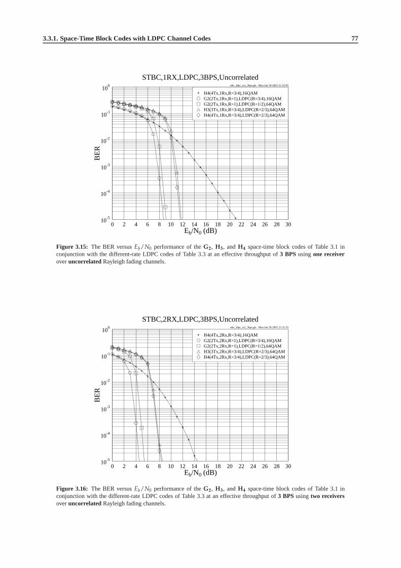
3.3.1. Space-Time Block Codes with LDPC Channel Codes 77
stbc_ldpc_rx1_3bps.gle Mon Jun 30 2003 21:32:05
0 2 4 6 8 10 12 14 16 18 20 22 24 26 28 30Eb/N0 (dB)
10-5
10-4
10-3
10-2
10-1
100
BE
R
STBC,1RX,LDPC,3BPS,Uncorrelated
H4(4Tx,1Rx,R=3/4),LDPC(R=2/3),64QAMH3(3Tx,1Rx,R=3/4),LDPC(R=2/3),64QAMG2(2Tx,1Rx,R=1),LDPC(R=1/2),64QAMG2(2Tx,1Rx,R=1),LDPC(R=3/4),16QAMH4(4Tx,1Rx,R=3/4),16QAM
Figure 3.15: The BER versusEb/N0 performance of theG2, H3, andH4 space-time block codes of Table 3.1 inconjunction with the different-rate LDPC codes of Table 3.3at an effective throughput of3 BPSusingone receiveroveruncorrelated Rayleigh fading channels.
stbc_ldpc_rx2_3bps.gle Mon Jun 30 2003 21:31:35
0 2 4 6 8 10 12 14 16 18 20 22 24 26 28 30Eb/N0 (dB)
10-5
10-4
10-3
10-2
10-1
100
BE
R
STBC,2RX,LDPC,3BPS,Uncorrelated
H4(4Tx,2Rx,R=3/4),LDPC(R=2/3),64QAMH3(3Tx,2Rx,R=3/4),LDPC(R=2/3),64QAMG2(2Tx,2Rx,R=1),LDPC(R=1/2),64QAMG2(2Tx,2Rx,R=1),LDPC(R=3/4),16QAMH4(4Tx,2Rx,R=3/4),16QAM
Figure 3.16: The BER versusEb/N0 performance of theG2, H3, andH4 space-time block codes of Table 3.1 inconjunction with the different-rate LDPC codes of Table 3.3at an effective throughput of3 BPSusingtwo receiversoveruncorrelated Rayleigh fading channels.

78 Chapter3. Channel Coding Assisted STBC-OFDM Systems
3.3.1.2.2 Performance over Correlated Rayleigh Fading Channels
We have compared the performance of the LDPC-aided space-time block codes when communicating over uncorre-lated Rayleigh fading channels in Section 3.3.1.2.1. In this section, the performance of the STBC codes will be studiedbased on the same assumptions summarized on page 66, except that the channel is assumed to be a correlated Rayleighfading channel obeying the normalized Doppler frequency of3.25 × 10−5. The corresponding parameters are givenin Table 3.4.
In Section 3.2.5.2 it was found that if the effective throughput is a fixed constant, the performance of the variousspace-time codes used for transmission over uncorrelated and correlated Rayleigh fading channels is similar. However,in the context of the LDPC-assisted STBC-coded system, the achievable performances are different over uncorrelatedand correlated Rayleigh fading channels. This can be clearly seen by comparing Figures 3.17, 3.18 and 3.19 of thissection to Figures 3.13, 3.14 and 3.15 of Section 3.3.1.2.1,respectively. The reason for this phenomenon is that theLDPC codes perform better over uncorrelated rather than correlated Rayleigh fading channels, unless their codewordlength is extremely high or long channel interleavers are used. This will be demonstrated during our further discourse.
stbc_ldpc_rx1_1bps_cor.gle Mon Jun 30 2003 21:35:57
0 2 4 6 8 10 12 14 16 18 20 22 24 26 28 30Eb/N0 (dB)
10-5
10-4
10-3
10-2
10-1
100
BE
R
STBC,1RX,LDPC,1BPS,Correlated
H4(4Tx,1Rx,R=3/4),LDPC(R=2/3),QPSKH3(3Tx,1Rx,R=3/4),LDPC(R=2/3),QPSKG4(4Tx,1Rx,R=1/2),LDPC(R=1/2),16QAMG3(3Tx,1Rx,R=1/2),LDPC(R=1/2),16QAMG2(2Tx,1Rx,R=1),LDPC(R=1/2),QPSKG4(4Tx,1Rx,R=1/2),QPSK(1Tx,1Rx),BPSK
Figure 3.17: The BER versusEb/N0 performance of theG2, G3, G4, H3, andH4 space-time block codes of Table 3.1in conjunction with the different-rate LDPC codes of Table 3.4 at an effective throughput of1 BPSusingone receiverovercorrelated Rayleigh fading channels. The normalized Doppler frequency is 3.25 × 10⁻⁵.
Performance at the Throughput of 1 BPS Figure 3.17 shows the achievable performance of the LDPC-assistedG2, G3, G4, H3 andH4 codes of Table 3.1 using one receiver at the effective throughput of 1 BPS when communicatingover correlated Rayleigh fading channels. We can see that the 2
3 -rate LDPC-codedH4 andH3 codes outperform the23 -rate LDPC-codedG4 andG3 codes by about 1dB, respectively. However, whenEb/N0 is lower than about 8dB,we notice that the scheme employing the unprotectedG4 code, which is the best design option at the throughput of1 BPS according to Table 3.2, performs better than the schemeemploying the2
3 -rate LDPC-aidedH4 code. Whenthe SNR is increased to 15dB, the situation is reversed, since the unprotectedG4 scheme is outperformed by the bestLDPC-STBC scheme, namely the2
3 -rate LDPC-assistedH4 coded scheme, with about 1dBEb/N0 degradation at theBER of10−5.
Performance at the Throughput of 2 BPS At an effective throughput of approximately 2 BPS, the relevantschemes’ performances are given in Figure 3.18. It is seen inthe figure that the performance of the schemes employingthe H4 andH3 codes of Table 3.1 is similar to those of the schemes employing theG4 andG3 codes, respectively,although we may bear in mind that the3
4 -rateH4 andH3 codes have an effective throughput of 2.25 BPS, rather thanexactly 2 BPS. Furthermore, an important phenomenon found in Figure 3.18 is that the best unprotected STBC schemeof Figure 3.6 also attains the best performance in this new scenario.
This result may be explained as follows. The performance of the unprotected space-time block codes remainssimilar over uncorrelated or correlated Rayleigh fading channels, as it was indicated in Section 3.2.5.2. Furthermore,
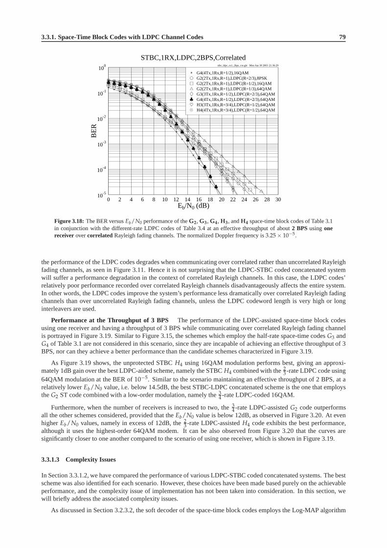
3.3.1. Space-Time Block Codes with LDPC Channel Codes 79
stbc_ldpc_rx1_2bps_cor.gle Mon Jun 30 2003 21:36:29
0 2 4 6 8 10 12 14 16 18 20 22 24 26 28 30Eb/N0 (dB)
10-5
10-4
10-3
10-2
10-1
100
BE
R
STBC,1RX,LDPC,2BPS,Correlated
H4(4Tx,1Rx,R=3/4),LDPC(R=1/2),64QAMH3(3Tx,1Rx,R=3/4),LDPC(R=1/2),64QAMG4(4Tx,1Rx,R=1/2),LDPC(R=2/3),64QAMG3(3Tx,1Rx,R=1/2),LDPC(R=2/3),64QAMG2(2Tx,1Rx,R=1),LDPC(R=1/3),64QAMG2(2Tx,1Rx,R=1),LDPC(R=1/2),16QAMG2(2Tx,1Rx,R=1),LDPC(R=2/3),8PSKG4(4Tx,1Rx,R=1/2),16QAM
Figure 3.18: The BER versusEb/N0 performance of theG2, G3, G4, H3, andH4 space-time block codes of Table 3.1in conjunction with the different-rate LDPC codes of Table 3.4 at an effective throughput of about2 BPSusingonereceiver overcorrelated Rayleigh fading channels. The normalized Doppler frequency is 3.25 × 10⁻⁵.
the performance of the LDPC codes degrades when communicating over correlated rather than uncorrelated Rayleighfading channels, as seen in Figure 3.11. Hence it is not surprising that the LDPC-STBC coded concatenated systemwill suffer a performance degradation in the context of correlated Rayleigh channels. In this case, the LDPC codes’relatively poor performance recorded over correlated Rayleigh channels disadvantageously affects the entire system.In other words, the LDPC codes improve the system’s performance less dramatically over correlated Rayleigh fadingchannels than over uncorrelated Rayleigh fading channels,unless the LDPC codeword length is very high or longinterleavers are used.
Performance at the Throughput of 3 BPS The performance of the LDPC-assisted space-time block codesusing one receiver and having a throughput of 3 BPS while communicating over correlated Rayleigh fading channelis portrayed in Figure 3.19. Similar to Figure 3.15, the schemes which employ the half-rate space-time codesG3 andG4 of Table 3.1 are not considered in this scenario, since they are incapable of achieving an effective throughput of 3BPS, nor can they achieve a better performance than the candidate schemes characterized in Figure 3.19.
As Figure 3.19 shows, the unprotected STBCH4 using 16QAM modulation performs best, giving an approxi-mately 1dB gain over the best LDPC-aided scheme, namely the STBC H4 combined with the2
3 -rate LDPC code using64QAM modulation at the BER of10−5. Similar to the scenario maintaining an effective throughput of 2 BPS, at arelatively lowerEb/N0 value, i.e. below 14.5dB, the best STBC-LDPC concatenated scheme is the one that employstheG2 ST code combined with a low-order modulation, namely the3
4 -rate LDPC-coded 16QAM.
Furthermore, when the number of receivers is increased to two, the 34 -rate LDPC-assistedG2 code outperforms
all the other schemes considered, provided that theEb/N0 value is below 12dB, as observed in Figure 3.20. At evenhigherEb/N0 values, namely in excess of 12dB, the2
3 -rate LDPC-assistedH4 code exhibits the best performance,although it uses the highest-order 64QAM modem. It can be also observed from Figure 3.20 that the curves aresignificantly closer to one another compared to the scenarioof using one receiver, which is shown in Figure 3.19.
3.3.1.3 Complexity Issues
In Section 3.3.1.2, we have compared the performance of various LDPC-STBC coded concatenated systems. The bestscheme was also identified for each scenario. However, thesechoices have been made based purely on the achievableperformance, and the complexity issue of implementation has not been taken into consideration. In this section, wewill briefly address the associated complexity issues.
As discussed in Section 3.2.3.2, the soft decoder of the space-time block codes employs the Log-MAP algorithm

80 Chapter3. Channel Coding Assisted STBC-OFDM Systems
stbc_ldpc_rx1_3bps_cor.gle Mon Jun 30 2003 21:36:56
0 2 4 6 8 10 12 14 16 18 20 22 24 26 28 30Eb/N0 (dB)
10-5
10-4
10-3
10-2
10-1
100
BE
RSTBC,1RX,LDPC,3BPS,Correlated
H4(4Tx,1Rx,R=3/4),LDPC(R=2/3),64QAMH3(3Tx,1Rx,R=3/4),LDPC(R=2/3),64QAMG2(2Tx,1Rx,R=1),LDPC(R=1/2),64QAMG2(2Tx,1Rx,R=1),LDPC(R=3/4),16QAMH4(4Tx,1Rx),16QAM
Figure 3.19: The BER versusEb/N0 performance of theG2, H3, andH4 space-time block codes of Table 3.1 inconjunction with the different-rate LDPC codes of Table 3.4at an effective throughput of3 BPSusingone receiverovercorrelated Rayleigh fading channels. The normalized Doppler frequency is 3.25 × 10⁻⁵.
stbc_ldpc_rx2_3bps_cor.gle Mon Jun 30 2003 21:37:30
0 2 4 6 8 10 12 14 16 18 20 22 24 26 28 30Eb/N0 (dB)
10-5
10-4
10-3
10-2
10-1
100
BE
R
STBC,2RX,LDPC,3BPS,Correlated
H4(4Tx,2Rx,R=3/4),LDPC(R=2/3),64QAMH3(3Tx,2Rx,R=3/4),LDPC(R=2/3),64QAMG2(2Tx,2Rx,R=1),LDPC(R=1/2),64QAMG2(2Tx,2Rx,R=1),LDPC(R=3/4),16QAMH4(4Tx,2Rx),16QAM
Figure 3.20: The BER versusEb/N0 performance of theG2, H3, andH4 space-time block codes of Table 3.1 inconjunction with the different-rate LDPC codes of Table 3.4at an effective throughput of3 BPSusingtwo receiversovercorrelated Rayleigh fading channels. The normalized Doppler frequency is 3.25 × 10⁻⁵.

3.3.1. Space-Time Block Codes with LDPC Channel Codes 81
summarized for example in [359]. With the advent of the Log-MAP algorithm, the high-complexity complicatedexponential operations are substituted by additions and subtractions carried out in the logarithmic domain. Hencethe complexity of the STBC decoder is significantly reduced,while closely matching the performance of the MAPalgorithm. In our following discussions, the decoding complexity of the space-time bock codes is considered to besufficiently low for it to be ignored for the sake of simplifying our comparisons. This will not affect our conclusions,since we will show in the rest of this section that the LDPC-assistedG2 code, which has the lowest decoding com-plexity among all the space-time block codes of Table 3.1, gives the best performance as seen in Figures 3.21, 3.22and 3.23. Hence, even if the decoding complexity of the space-time block codes is considered, theG2 code will stillbe superior to the other STBCs in the context of the coding gain versus complexity performance.
The decoding complexity per information bit per iteration of the LDPC codes can be calculated as follows [434]:
comp LDPC =
(
5 − R
1 − R
)
· j2, (3.30)
whereR is the LDPC code’s code rate andj is the column weights of the parity check matrix. In our system the valueof column weights was fixed to 3, thus Equation (3.30) is simplified to:
comp LDPC =
(
45 − 9R
1 − R
)
. (3.31)
According to Equation (3.31), the decoding complexity is essentially based on the code rate of the LDPC code em-ployed. Thus for the rate 1/3, 1/2, 2/3 and 3/4 LDPC codes usedin our system, the associated decoding complexityper bit per iteration becomes 63, 81, 117 and 153 additions and subtractions, respectively, as summarized in Table 3.5.
stbc_ldpc_comp_vs_cg_1bps.gle Mon Jun 30 2003 21:40:01
0 500 1000 1500 2000 2500 3000 3500 4000Complexity
20
25
30
35
40
45
Cod
ing
Gai
n(d
B)
Coding Gain v.s Complexity, 1BPS, Uncorrelated
H4(4Tx,1Rx,R=3/4),LDPC(R=2/3),QPSKH3(3Tx,1Rx,R=3/4),LDPC(R=2/3),QPSKG4(4Tx,1Rx,R=1/2),LDPC(R=1/2),16QAMG3(3Tx,1Rx,R=1/2),LDPC(R=1/2),16QAMG2(2Tx,1Rx,R=1),LDPC(R=1/2),QPSK
Figure 3.21: Coding gain versus estimated complexity for the LDPC-STBC coded concatenated schemes using onereceiver, when communicating over uncorrelated Rayleigh fading channels at the effective throughput of1 BPS. Thesimulation parameters are given in Table 3.3.
Let us now compare the coding gain versus complexity characteristics of the different schemes considered, as seenfrom Figures 3.21 to 3.23, where the parameters used are given in Table 3.3. The coding gain here is defined as theEb/N0 difference, expressed in terms of decibels, at a BER of10−5 between the various channel codes assisted space-time block coded systems and the uncoded single-transmitter systems having the same throughput. All the estimatedimplementational complexities were calculated based on Equation (3.31), using different number of iterations rangingfrom 1 to 40 with a step of about 5.
At an effective throughput of 1 and 2 BPS, as seen in Figures 3.21 and 3.22, it was found that the best scheme wasthe half-rate LDPC-codedG2 space-time code. In the scenario of having an effective throughput of 3 BPS, the perfor-mance curves of the half-rate and3
4 -rate LDPC-codedG2 space-time code are close to each other, although the formerperforms slightly better. We may also note that the coding gain increases dramatically in the low-complexity range

82 Chapter3. Channel Coding Assisted STBC-OFDM Systems
stbc_ldpc_comp_vs_cg_2bps.gle Mon Jun 30 2003 21:40:47
0 500 1000 1500 2000 2500 3000 3500 4000Complexity
20
25
30
35
40
45
Cod
ing
Gai
n(d
B)
Coding Gain v.s Complexity, 2BPS, Uncorrelated
H4(4Tx,1Rx,R=3/4),LDPC(R=1/2),64QAMH3(3Tx,1Rx,R=3/4),LDPC(R=1/2),64QAMG4(4Tx,1Rx,R=1/2),LDPC(R=2/3),64QAMG3(3Tx,1Rx,R=1/2),LDPC(R=2/3),64QAMG2(2Tx,1Rx,R=1),LDPC(R=1/3),64QAMG2(2Tx,1Rx,R=1),LDPC(R=1/2),16QAMG2(2Tx,1Rx,R=1),LDPC(R=2/3),8PSK
Figure 3.22: Coding gain versus estimated complexity for the LDPC-STBC coded concatenated schemes using onereceiver, when communicating over uncorrelated Rayleigh fading channels at the effective throughput of2 BPS. Thesimulation parameters are given in Table 3.3.
stbc_ldpc_comp_vs_cg_3bps.gle Mon Jun 30 2003 21:41:13
0 500 1000 1500 2000 2500 3000 3500 4000Complexity
20
25
30
35
40
45
Cod
ing
Gai
n(d
B)
Coding Gain v.s Complexity, 3BPS, Uncorrelated
H4(4Tx,1Rx,R=3/4),LDPC(R=2/3),64QAMH3(3Tx,1Rx,R=3/4),LDPC(R=2/3),64QAMG2(2Tx,1Rx,R=1),LDPC(R=1/2),64QAMG2(2Tx,1Rx,R=1),LDPC(R=3/4),16QAM
Figure 3.23: Coding gain versus estimated complexity for the LDPC-STBC coded concatenated schemes using onereceiver, when communicating over uncorrelated Rayleigh fading channels at the effective throughput of3 BPS. Thesimulation parameters are given in Table 3.3.

3.3.1. Space-Time Block Codes with LDPC Channel Codes 83
and tends to saturate in the vicinity of an estimated complexity of about 1200, which corresponds to approximately 19,15, 10 and 8 iterations for the LDPC codes having a code rate of1
3 , 12 , 2
3 and 34 , respectively. As Figure 3.24 shows,
for example, when the number of iterations is increased to about 10 in terms of the half-rate LDPC-aidedG2 code,the performance is already close to the achievable maximum coding gain. This result can be considered as a rule ofthumb for setting the number of iterations for the LDPC-STBCcoded concatenated schemes, when aiming for a goodtradeoff in terms of the achievable performance-to-complexity relationships.
stbc_ldpc_iter_vs_cg.gle Mon Jun 30 2003 21:43:36
0 5 10 15 20 25 30 35 40Number of Iterations
20
25
30
35
40
45
Cod
ing
Gai
n(d
B)
Coding Gain v.s Number of Iterations, Uncorrelated
G2(2Tx,1Rx,R=1),LDPC(R=1/2),64QAM,3BPSG2(2Tx,1Rx,R=1),LDPC(R=1/2),16QAM,2BPSG2(2Tx,1Rx,R=1),LDPC(R=1/2),QPSK,1BPS
Figure 3.24: Coding gain versus the number of iterations for the half-rate LDPC-assistedG2 space-time block codedschemes using one receiver, when communicating over uncorrelated Rayleigh fading channels at the effective throughputof 1, 2 and 3 BPS. The parameters used are given in Table 3.3.
In Figure 3.25, we show theEb/N0 value required for maintaining a BER of10−5 versus the effective throughputBPS for the unprotected space-time block codes and the half-rate LDPC-assistedG2 code, while the associated simu-lation parameters are summarized in Tables 3.1 and 3.3. The simulation results were obtained using one receiver forcommunicating over uncorrelated Rayleigh fading channels. It can be observed in Figure 3.25 that theEb/N0 valuerequired for maintaining a BER of10−5 increases near-linearly, as the effective BPS throughput increases. This con-clusion was valid for both the unprotected STBC-aided schemes and for the half-rate LDPC-assistedG2 coded scheme.Furthermore, the half-rate LDPC-G2 concatenated scheme achieves a gain of about 15dB over the best unprotectedSTBC scheme at the effective throughput values of 1, 2 and 3 BPS, respectively.
3.3.1.4 Conclusions
Having studied Figures 3.13 to 3.19, we may arrive at the following conclusions. First of all, as expected, the LDPC-aided STBC-coded schemes perform significantly better thanthe unprotected STBC schemes, when transmitting overuncorrelated Rayleigh fading channels. However, over correlated Rayleigh fading channels the performance improve-ments achieved by the LDPC codes are not as significant as in uncorrelated Rayleigh fading channels, as seen inFigures 3.17 to 3.20. This is because the LDPC codes suffer from their finite codeword length and for a limitedtolerable channel interleaver delay, as evidenced by Figure 3.11. This affects the attainable performance of the LDPC-STBC coded concatenated system to some degree. If we use an extremely long codeword or employ a long channelinterleaver, however, the achievable performance of the LDPC-STBC concatenated schemes can be improved in thecontext of correlated Rayleigh fading channels.
Another observation inferred from Figures 3.13 to 3.19 is that when the number of receiver antennas is increased,most of the attainable diversity gain has already been achieved by the LDPC-G2 coded concatenated schemes. Hence,the employment of a space-time block code using more transmitter antennas will introduce a higher-throughput mod-ulation mode, which in turn will require an increasedEb/N0 value and hence degrades the achievable performance.
Furthermore, in the context of uncorrelated Rayleigh fading channels and using a specific modulation scheme,

84 Chapter3. Channel Coding Assisted STBC-OFDM Systems
stbc_ldpc_bps_vs_ebn0.gle Mon Jun 30 2003 21:44:18
0 1 2 3 4BPS
0
10
20
30
40E
b/N
0C
ross
ing
Poi
ntat
BE
R=
10-5
Eb/N0 v.s BPS, Uncorrelated
H4(R=3/4)H3(R=3/4)G4(R=1/2)G3(R=1/2)G2(R=1)G2(R=1),LDPC(R=1/2)
Figure 3.25: TheEb/N0 value required for maintaining BER=10−5 versus the effective BPS throughput for the space-time block codes of Table 3.1 and for the half-rate LDPC-assistedG2 code of Table 3.3, when using one receiver andcommunicating over uncorrelated Rayleigh fading channels.
the LDPC-STBC coded system’s performance is mainly decidedby the code-rate and error correction capability ofthe LDPC code employed, instead of the space-time codes’ diversity order. In this case, using a lower-rate LDPCcode will achieve a more substantial performance improvement than increasing the number of transmitters and theassociated diversity gain. On the other hand, if the same LDPC code is employed, the throughput of the modulationscheme has more influence on the system’s performance than the diversity order. In other words, the benefits broughtabout by the employment of low-throughput modulation schemes will be more substantial than that offered by a high-order space-time block code, provided that both schemes areassisted by the same LDPC code. The reason behindthis phenomenon is that when the higher-order STBC codes areused in conjunction with a high number of antennas,more vulnerable high-throughput modulation schemes have to be used, for the sake of maintaining the same effectivethroughput. Therefore the employment of the latter scenario would result in performance degradations. In summary,the best candidate schemes are the ones using the LDPC-aidedG2 code when communicating over uncorrelatedRayleigh fading channels. When using the same space-time block code, the complexity of the STBC code can beignored during our comparisons.
Another useful conclusion can be drawn from Figure 3.24. As seen in the figure, the coding gains of the LDPC-aided schemes tend to remain unimproved, even if the affordable complexity increases to a certain degree, althoughthe validity of this statement depends on the specific choiceof the LDPC code used. This result assists us in decidingon the appropriate number of iterations to be used by the LDPC-STBC concatenated schemes, so that the achievablebest possible performance-to-complexity tradeoff can be achieved.
Before concluding this section, we summarize the achievable performance of the different schemes used in ourvarious candidate systems communicating over uncorrelated Rayleigh fading channels in Table 3.5. For the scenariosof having an effective throughput of 1, 2 and 3 BPS, respectively, the corresponding bold numbers denote the bestscheme based on the criterion of achieving the best coding gain versus complexity tradeoff, as seen in Figures 3.21,3.22 and 3.23. As a result, the half-rate LDPC-coded space-time block codeG2 was found to be the best scheme inthe scenarios having an effective throughput of 1 and 2 BPS, while the 3
4 -rate LDPC-codedG2 code performs best inthe scenario of having an effective throughput of 3 BPS.
3.3.2 LDPC-Aided and TC-Aided Space-Time Block Codes
In Section 3.3.1, we have studied the performance of variousLDPC-aided space-time block coded systems. It has beenfound that the LDPC codes considerably improve the STBC-coded system’s performance over uncorrelated Rayleighfading channels. However, besides LDPC channel codes, the space-time block codes can also be concatenated with

3.3.2. LDPC-Aided and TC-Aided Space-Time Block Codes 85
Eb/N0 (dB) Gain (dB)
BPS STBC LDPC LDPC BER Modem
Code Rate Compl. 10−3 10−5 10−3 10−5
Uncoded - - 24.22 44.00 0.00 0.00 BPSK
G4 - - 10.10 15.85 14.12 28.15 QPSK
G2 1/2 81 2.99 3.61 21.23 40.39 QPSK
1.00 G3 1/2 81 5.17 5.92 19.05 38.08 16QAM
G4 1/2 81 4.95 5.79 19.27 38.21 16QAM
H3 2/3 117 4.65 5.56 19.57 38.44 QPSK
H4 2/3 117 4.41 5.24 19.81 38.76 QPSK
Uncoded - - 24.22 44.00 0.00 0.00 QPSK
G4 - - 13.61 19.58 10.61 24.42 16QAM
G2 2/3 117 6.05 6.89 18.17 37.11 8PSK
2.00 G2 1/2 81 5.45 6.18 18.77 37.82 16QAM
G2 1/3 63 7.10 7.90 17.12 36.10 64QAM
G3 2/3 117 9.65 10.81 14.57 33.19 64QAM
G4 2/3 117 9.34 10.40 14.88 33.60 64QAM
2.25 H3 1/2 81 9.20 9.96 15.02 34.04 64QAM
≈ 2.00 H4 1/2 81 9.02 9.73 15.20 34.27 64QAM
Uncoded - - 26.30 46.26 0.00 0.00 8PSK
H4 - - 14.87 21.10 11.43 25.16 16QAM
3.00 G2 3/4 153 7.73 8.68 18.57 37.58 16QAM
G2 1/2 81 8.33 9.13 17.97 37.13 64QAM
H3 2/3 117 10.85 11.75 15.45 34.51 64QAM
H4 2/3 117 10.58 11.57 15.72 34.69 64QAM
Table 3.5: Coding gains of the LDPC-STBC coded concatenated schemes using one receiver, when communicating
over uncorrelated Rayleigh fading channels. With reference to Figures 3.21, 3.22 and 3.23, the performance of the best
scheme is printed in bold for the scenarios of having different effective throughputs, respectively.
a range of other channel codes, such as Convolutional Codes (CC), Turbo Convolutional (TC) codes [423, 424],Turbo Bose-Chaudhuri-Hocquenghem (TBCH) codes [435], etc. The performance of these various channel-codedG2 schemes designed for transmission over uncorrelated Rayleigh fading channels has been studied in [359], wherethe best scheme found was the half-rate TC(2,1,4) code in conjunction with the space-time block codeG2. Hence,in this section, we will compare the performance of the best LDPC-STBC coded concatenated scheme found inSection 3.3.1.2, namely that of the half-rate LDPC-aidedG2 code, with the half-rate TC(2,1,4)-aided space-time blockcoded schemes.
3.3.2.1 System Overview
In 1993, Berrouet al. [423,424] proposed a novel channel code, referred to as a turbo code. As detailed in [359], theturbo encoder consists of two component encoders. Generally, convolutional codes are used as the component encodersand the corresponding turbo codes are termed here as TC codes. For a TC(n, k, K) code, the three parametersn, kandK have the same meaning as in a convolutional code CC(n, k, K), wherek is the number of input bits,n is thenumber of coded bits andK is the constraint length of the code. More details about TC codes can be found in [359].The schematic of our experimental system, where the half-rate TC(2,1,4) code is employed, is given in Figure 3.26.

86 Chapter3. Channel Coding Assisted STBC-OFDM Systems
Source
Sink
TC(2,1,4)
Encoder
Channel
Interleaver
STBC
Encoder
Channel
TC(2,1,4)
Decoder
Channel
Deinterleaver
STBC
Soft Decoder
…
…
Mapper
Soft
Demapper
Figure 3.26: Overview of the space-time block coded and TC(2,1,4) channel coded system.
The source bits are first encoded by the half-rate TC(2,1,4) encoder. The Log-MAP decoding algorithm [359]is utilized for iterative turbo decoding, since it operatesin the logarithmic domain and thus significantly reduces thecomputational complexity imposed by the MAP algorithm [428]. The number of turbo iterations is set to eight, sincethis yields a performance close to the achievable performance associated with an infinite number of iterations. The TC-encoded bits will be interleaved by the channel interleaver, as seen in Figure 3.26. In this case, a random interleaverhaving a depth of about 20,000 is used. The interleaved bits will then be forwarded to the mapper, followed by theSTBC encoder. At the receiver side, the corresponding inverse operations are invoked, as seen in Figure 3.26. Thesimulation parameters of the TC-STBC coded concatenated system are given in Table 3.6.
STBC TC(2,1,4)
Random Random
BPS Code Code Turbo Channel Code Puncturing Iter- Total Modem
Rate Interleaver Interleaver Rate Pattern ations Compl.
Depth Depth
G2 1 10000 20000 1/2 10,01 8 2576 QPSK
1.00 G3 1/2 10000 20000 1/2 10,01 8 2576 16QAM
G4 1/2 10000 20000 1/2 10,01 8 2576 16QAM
2.00 G2 1 10000 20000 1/2 10,01 8 2576 16QAM
3.00 G2 1 10002 20004 1/2 10,01 8 2576 64QAM
Table 3.6: The parameters used in the TC(2,1,4)-STBC coded concatenated schemes.
3.3.2.2 Complexity Issues
For the sake of fair comparisons, we should calculate and take into account the complexity of the LDPC and TC(2,1,4)codes. The total estimated complexity of the TC codes per information bit per iteration in terms of additions andsubtractions to be carried out is [436]:
comp TC (n, 1, K) = 40(
2K−1)
+ 12n − 22. (3.32)
According to Equation (3.32), the complexity of the TC(2,1,4) code is 322 per information bit per iteration. Since thenumber of iterations has been set to eight, the total complexity of the TC(2,1,4) code per bit is322 × 8 = 2576 in thecontext of additions and subtractions, as shown in Table 3.6.
On the other hand, the complexity of the LDPC codes per information bit per iteration can be calculated accordingto Equation (3.31). Therefore, we can multiply the result ofEquation (3.31) with the appropriately selected numberof iterations required by the different-rate LDPC codes, sothat a similar complexity per bit is used for both the LDPCcodes and for the TC(2,1,4) code. For the half-rate LDPC-codedG2 scheme, the number of iterations was set to 32 sothat the total complexity becomes81 × 32 = 2592, which is close to the estimated complexity of 2576 encounteredby the TC(2,1,4) scheme. The parameters of the LDPC-G2 coded concatenated scheme used in this new scenario aregiven in Table 3.7.

3.3.2. LDPC-Aided and TC-Aided Space-Time Block Codes 87
STBC LDPC
Input Output Inter-
BPS Code Code Code Bits Bits Column Iter- Total leaver Modem
Rate Rate Block Block Weight ations Compl. Depth
Size Size
1.00 G2 1 1/2 10000 20000 3 32 2592 20000 QPSK
2.00 G2 1 1/2 10000 20000 3 32 2592 20000 16QAM
3.00 G2 1 1/2 10002 20004 3 32 2592 20004 64QAM
Table 3.7: The parameters used in the LDPC-G2 coded concatenated schemes invoked for comparison with the
TC(2,1,4)-G2 coded concatenated schemes.
3.3.2.3 Simulation Results
In this section, the performance of the LDPC- and TC-aided space-time block coded schemes communicating overuncorrelated Rayleigh fading channels will be studied and compared. The parameters of the space-time block codes,the half-rate TC(2,1,4) code and the LDPC codes are given in Tables 3.1, 3.6 and 3.7, respectively. The simulationresults are based on the same assumptions which were outlined in Section 3.2.4 on page 66.
stbc_ldpc_tc214_rx1_1bps.gle Mon Jun 30 2003 21:47:07
0 2 4 6 8 10 12 14 16 18 20Eb/N0(dB)
10-5
10-4
10-3
10-2
10-1
100
BE
R
G2+LDPC v.s G2/G3/G4+TC(2,1,4), 1BPS, Uncorrelated
G4(4Tx,1Rx,R=1/2),TC(2,1,4)(R=1/2),16QAMG3(3Tx,1Rx,R=1/2),TC(2,1,4)(R=1/2),16QAMG2(2Tx,1Rx,R=1),TC(2,1,4)(R=1/2),QPSKG2(2Tx,1Rx,R=1),LDPC(R=1/2),QPSKG4(4Tx,1Rx,R=1/2),QPSK(1Tx,1Rx),BPSK
Figure 3.27: The BER versusEb/N0 performance of theG2, G3 and G4 space-time block codes of Table 3.1 inconjunction with the LDPC codes of Table 3.7 or the half-rateTC(2,1,4) code of Table 3.6 at an effective throughput of1 BPSusing one receiver over uncorrelated Rayleigh fading channels.
Figure 3.27 compares the performance of the candidate schemes using the parameters summarized in Tables 3.6and 3.7 operating at an effective throughput of 1 BPS over uncorrelated Rayleigh fading channels. For the half-rateTC(2,1,4) coded scheme combined with the half-rateG3 andG4 codes, the 16QAM modem is used for maintaininga throughput of 1 BPS. As seen in Figure 3.27, the TC(2,1,4)-aided G2 code outperforms the others. However, atthe BER of10−5, it only provides an approximately 0.1dB gain over the LDPC-aidedG2 code, which is the bestLDPC-STBC coded concatenated scheme according to Table 3.5. It is also observed that the schemes in which theG3
andG4 codes are employed exhibit an inferior performance in comparison to theirG2-code based counterpart as wellas in comparison to the LDPC-aided scheme, because the more densely-packed 16QAM phasor constellation is used.
Figure 3.28 compares the performance of the candidate schemes using the parameters summarized in Tables 3.6

88 Chapter3. Channel Coding Assisted STBC-OFDM Systems
and 3.7 operating at an effective throughput of 2 and 3 BPS over uncorrelated Rayleigh fading channels. As suggestedby Figure 3.28, the TC(2,1,4)-aided schemes perform slightly better, than the LDPC-aided schemes providing anapproximately 0.1dB and 0.4dB gain at the BER of10−5 in the scenarios of having a throughput of 2 and 3 BPS,respectively.
stbc_ldpc_tc214_rx1_23bps.gle Mon Jun 30 2003 21:47:41
0 2 4 6 8 10 12 14 16 18 20Eb/N0(dB)
10-5
10-4
10-3
10-2
10-1
100
BE
R
G2+LDPC v.s G2+TC(2,1,4), Uncorrelated
3BPS: G2(2Tx,1Rx,R=1),TC(2,1,4)(R=1/2),64QAM3BPS: G2(2Tx,1Rx,R=1),LDPC(R=1/2),64QAM3BPS: H4(4Tx,1Rx,R=3/4),16QAM2BPS: G2(2Tx,1Rx,R=1),TC(2,1,4)(R=1/2),16QAM2BPS: G2(2Tx,1Rx,R=1),LDPC(R=1/2),16QAM2BPS: G4(4Tx,1Rx,R=1/2),16QAM
Figure 3.28: The BER versusEb/N0 performance of theG2 space-time block code of Table 3.1 in conjunction withthe LDPC codes of Table 3.7 or the half-rate TC(2,1,4) code ofTable 3.6 at an effective throughput of2 and3 BPSusingone receiver over uncorrelated Rayleigh fading channels.
In Figure 3.29 the achievable coding gain versus complexityis characterized. The coding gains were recordedat the BER of10−5, as presented in Section 3.3.1.3. From Figure 3.29, we inferthat the curves associate with theTC(2,1,4) code are close to those of the LDPC codes, althoughthe former ones perform slightly better than the latterones in the context of having the same effective throughput of 1, 2 and 3 BPS, respectively. However, in the lowcomplexity range, namely in the complexity range spanning from 0 to 600, the LDPC codes perform better than theTC(2,1,4) code. On one hand, the achievable lowest complexity of the half-rate TC(2,1,4) code is 322, which isattained when the number of iterations is set to one, while the LDPC codes are capable of providing an even lowercomplexity down to 81, again, as seen in Figure 3.29. On the other hand, for the LDPC schemes, the achievablecoding gain dramatically increases, when the affordable complexity is increased within the range spanning from 0 toabout 600. Therefore, the employment of the LDPC-aided schemes may be more attractive in scenarios, where theaffordable complexity is the most important concern, whilethe system’s performance does not necessarily have to bethe best.
3.3.2.4 Conclusions
In Section 3.3.2.3 we have presented a range of performance comparisons in the context of the attainable coding gainversus complexity for the various TC(2,1,4)-STBC and the LDPC-STBC coded concatenated schemes for transmis-sion over uncorrelated Rayleigh fading channels. As a conclusion, the TC(2,1,4)-assisted space-time block codeG2
outperforms its LDPC-assisted counterparts for all the three scenarios having different effective throughputs. How-ever, it was found that the associated performance difference is insignificant, namely less than 0.3dB. Furthermore,the LDPC-STBC coded concatenated schemes considered may bepreferred for employment in systems, where theseverity of complexity constraint outweighs the importance of achieving the highest possible performance.
Finally, the performance of the different schemes studied is summarized in Table 3.8. All the results were generatedusing a single receiver, when communicating over uncorrelated Rayleigh fading channels. The performance of the bestscheme at the effective throughputs of 1, 2 and 3 BPS is printed in bold, respectively.

3.3.2. LDPC-Aided and TC-Aided Space-Time Block Codes 89
stbc_ldpc_tc214_comp_vs_cg.gle Mon Jun 30 2003 21:50:55
0 500 1000 1500 2000 2500 3000 3500 4000Complexity
20
25
30
35
40
45
Cod
ing
Gai
n(d
B)
Coding Gain v.s Complexity, Uncorrelated
3BPS: G2,LDPC(R=1/2),64QAM3BPS: G2,TC(2,1,4)(R=1/2),64QAM2BPS: G2,LDPC(R=1/2),16QAM2BPS: G2,TC(2,1,4)(R=1/2),16QAM1BPS: G2,LDPC(R=1/2),QPSK1BPS: G2,TC(2,1,4)(R=1/2),QPSK
Figure 3.29: Coding gain versus complexity for the LDPC-G2 concatenated arrangements and for the TC(2,1,4)-G2
concatenated schemes using one receiver for communicatingover uncorrelated Rayleigh fading channels. The associatedparameters are given in Tables 3.6 and 3.7.
Eb/N0 (dB) Gain (dB)
BPS STBC LDPC TC(2,1,4) BER Modem
Code Rate Rate 10−3 10−5 10−3 10−5
Uncoded - - 24.22 44.00 0.00 0.00 BPSK
G4 - - 10.10 15.85 14.12 28.15 QPSK
1.00 G2 1/2 - 2.36 2.44 21.86 41.56 QPSK
G2 - 1/2 1.62 2.34 22.60 41.66 QPSK
G3 - 1/2 4.07 4.73 20.15 39.27 16QAM
G4 - 1/2 3.55 4.35 20.67 39.65 16QAM
Uncoded - - 24.22 44.00 0.00 0.00 QPSK
2.00 G4 - - 13.61 19.58 10.61 24.42 16QAM
G2 1/2 - 4.81 5.01 19.41 38.99 16QAM
G2 - 1/2 4.34 4.92 19.88 39.08 16QAM
Uncoded - - 26.30 46.26 0.00 0.00 8PSK
3.00 H4 - - 14.87 21.10 11.43 25.16 16QAM
G2 1/2 - 7.52 7.72 18.78 38.54 64QAM
G2 - 1/2 6.68 7.32 19.62 38.94 64QAM
Table 3.8: Coding gains of the LDPC-STBC concatenated schemes and the TC(2,1,4)-STBC concatenated schemes
using one receiver for communicating over uncorrelated Rayleigh fading channels. For the scenarios having different
effective throughputs, the performance of the best scheme is printed in bold.

90 Chapter3. Channel Coding Assisted STBC-OFDM Systems
3.4 Channel Coding Aided Space-Time Block Coded OFDM
In Section 3.3, we have investigated various LDPC channel coding assisted space-time block coded schemes commu-nicating over narrowband fading channels, followed by the performance study of LDPC-aided and TC-aided STBCschemes. Naturally, a range of channel codes can also be combined with the family of space-time block codes for thesake of improving the system’s performance. In this section, various Coded Modulation (CM) [359] assisted STBCschemes will be studied for transmission over multipath Rayleigh fading channels. Specifically, Trellis-Coded Mod-ulation (TCM) [359, 437], Turbo Trellis-Coded Modulation (TTCM) [359, 438], Bit-Interleaved Coded Modulation(BICM) [359, 439] and iterative joint decoding and demodulation assisted BICM (BICM-ID) [359, 440] will be in-vestigated. Furthermore, the above CM-assisted STBC aidedschemes will be studied in the context of a single-userOrthogonal Frequency Division Multiplexing (OFDM) [3–6] system. As a well-established technique, OFDM has ex-hibited a number of advantages over more traditional multiplexing techniques, and has been adopted for both DigitalAudio and Video Broadcasting (DAB and DVB) in Europe. It has also been selected as the IEEE 802.11 standards forWireless Local Area Network (WLAN). Let us now embark on the investigation of the CM-assisted space-time codedsingle-user OFDM system.
3.4.1 Coded Modulation Assisted Space-Time Block Codes
Since the signal bandwidth available for wireless communications is limited, one of the most important objectives inthe design of digital mobile systems is to make the most of theattainable bandwidth, for example with the aid of theCM schemes.
3.4.1.1 Coded Modulation Principles
The basic principle of CM [359] is that we attach a parity bit to each uncoded information symbol formed byminformation bits according to the specific modulation scheme used, hence doubling the number of constellation pointsto 2m+1 compared to that of2m in the original modem constellation. This is achieved by extending the modulationconstellation, rather than expanding the required bandwidth, while maintaining the same effective throughput ofmbits per symbol, as in the case of no channel coding. In other words, the signalling rate remains the same, since theredundant parity bit can be absorbed by the expansion of the constellation. Therefore, when the achievable codinggain of the CM scheme becomes higher than theEb/N0 degradation imposed by the more vulnerable higher-ordermodulation scheme employed, a useful effective coding gaincan be achieved.
Among the various CM schemes, TCM [437] was originally designed for transmission over Additive White Gaus-sian Noise (AWGN) channels. TTCM [438] is a more recent jointcoding and modulation scheme which has a structuresimilar to that of the family of binary turbo codes, but employs TCM schemes as component codes. Both TCM andTTCM employ set partitioning based constellation mapping [359], while using symbol-based turbo interleavers andchannel interleavers. Another CM scheme referred to as BICM[439], invokes bit-based channel interleavers in con-junction with gray constellation mapping. Furthermore, iteratively decoded BICM [440] using set partitioning wasalso proposed. More details about the various CM schemes used can be found in [359]. In this section, we will mostlyfocus on the performance of the proposed CM-assisted STBC coded OFDM schemes communicating over widebandRayleigh fading channels.
3.4.1.2 Inter-Symbol Interference and OFDM Basics
If the modulation bandwidth exceeds the coherence bandwidth of the channel, Inter-Symbol Interference (ISI) will beintroduced and the consecutive transmitted symbols are distorted, since the past and current symbols of the signalsare overlapped. Hence, at the receiver, channel equalizershave to be employed for the sake of removing the effects ofISI [359].
An alternative way of mitigating the effects of ISI is to employ OFDM, which effectively mitigates the detrimentaleffects of the frequency-selective fading, when transmitting over high-rate wideband channels. The basic principleof OFDM is to split a high-rate data stream into a number of low-rate streams which are transmitted simultaneouslyover a number of subcarriers. Hence the symbol duration is rendered longer for each of the parallel subcarriers, andthus the relative effects of imposed by the multipath channel’s delay spread is reduced. In other words, since thesystem’s data throughput is the sum of all the parallel sub-channels’ throughputs, the data rate per sub-channel is onlya small fraction of the total data rate of a conventional single-carrier system having the same throughput. This results
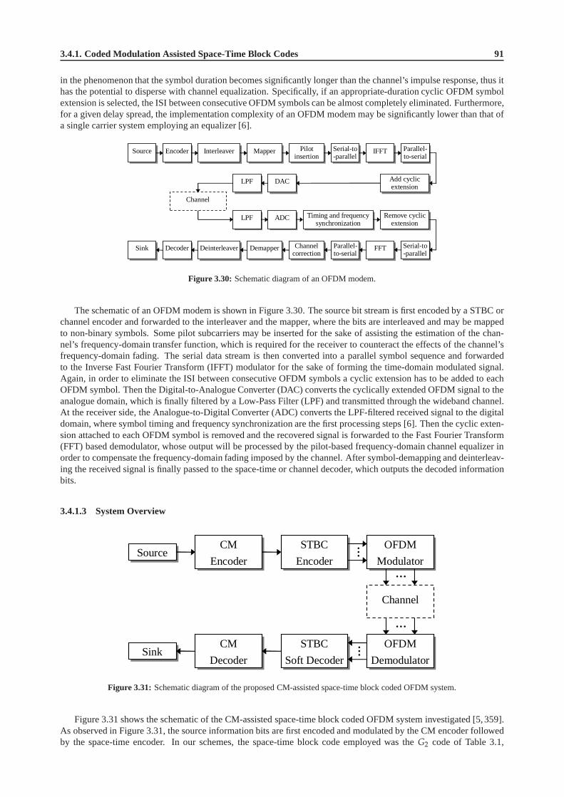
3.4.1. Coded Modulation Assisted Space-Time Block Codes 91
in the phenomenon that the symbol duration becomes significantly longer than the channel’s impulse response, thus ithas the potential to disperse with channel equalization. Specifically, if an appropriate-duration cyclic OFDM symbolextension is selected, the ISI between consecutive OFDM symbols can be almost completely eliminated. Furthermore,for a given delay spread, the implementation complexity of an OFDM modem may be significantly lower than that ofa single carrier system employing an equalizer [6].
Encoder
Decoder Demapper
Mapper Interleaver
Deinterleaver
Serial-to-parallel
Parallel-to-serial
FFT Serial-to-parallel
Parallel-to-serial
Add cyclic extension
Remove cyclic extension
DAC
ADC
LPF
LPF
Pilot insertion
Channel correction
Timing and frequency synchronization
Source IFFT
Sink
Channel
Figure 3.30: Schematic diagram of an OFDM modem.
The schematic of an OFDM modem is shown in Figure 3.30. The source bit stream is first encoded by a STBC orchannel encoder and forwarded to the interleaver and the mapper, where the bits are interleaved and may be mappedto non-binary symbols. Some pilot subcarriers may be inserted for the sake of assisting the estimation of the chan-nel’s frequency-domain transfer function, which is required for the receiver to counteract the effects of the channel’sfrequency-domain fading. The serial data stream is then converted into a parallel symbol sequence and forwardedto the Inverse Fast Fourier Transform (IFFT) modulator for the sake of forming the time-domain modulated signal.Again, in order to eliminate the ISI between consecutive OFDM symbols a cyclic extension has to be added to eachOFDM symbol. Then the Digital-to-Analogue Converter (DAC)converts the cyclically extended OFDM signal to theanalogue domain, which is finally filtered by a Low-Pass Filter (LPF) and transmitted through the wideband channel.At the receiver side, the Analogue-to-Digital Converter (ADC) converts the LPF-filtered received signal to the digitaldomain, where symbol timing and frequency synchronizationare the first processing steps [6]. Then the cyclic exten-sion attached to each OFDM symbol is removed and the recovered signal is forwarded to the Fast Fourier Transform(FFT) based demodulator, whose output will be processed by the pilot-based frequency-domain channel equalizer inorder to compensate the frequency-domain fading imposed bythe channel. After symbol-demapping and deinterleav-ing the received signal is finally passed to the space-time orchannel decoder, which outputs the decoded informationbits.
3.4.1.3 System Overview
Source
Sink
CM
Encoder
STBC
Encoder
OFDM
Modulator
Channel
CM
Decoder
STBC
Soft Decoder
OFDM
Demodulator
…
…
…
…
Figure 3.31: Schematic diagram of the proposed CM-assisted space-time block coded OFDM system.
Figure 3.31 shows the schematic of the CM-assisted space-time block coded OFDM system investigated [5,359].As observed in Figure 3.31, the source information bits are first encoded and modulated by the CM encoder followedby the space-time encoder. In our schemes, the space-time block code employed was theG2 code of Table 3.1,

92 Chapter3. Channel Coding Assisted STBC-OFDM Systems
which invokes two transmitter antennas, and the two space-time coded samples are mapped to two consecutive OFDMsubcarriers and OFDM modulated. Then the frequency-domainsymbols are converted to time-domain OFDM symbolsby the IFFT-based modulator and the cyclic extension is appended to each individual OFDM symbol. The OFDMsymbols are then transmitted via the multipath fading channel, and the received noise-contaminated symbols areforwarded to the OFDM demodulator, where the FFT operation will be employed for converting the channel-impairedtime-domain symbols to their frequency-domain counterparts. The recovered signal is then space-time soft-decodedand the soft outputs are fed to the CM decoder for recovering the most-likely transmitted information bits.
3.4.1.3.1 Complexity Issues
In order to compare the different candidate schemes under fair conditions, we chose the system parameters so that thedecoding complexity of the various CM schemes employed became similar. The complexity imposed by the STBCcodec was neglected, since the sameG2 space-time block code was used for all the CM-STBC concatenated schemes.
The symbol-based Log-MAP decoder [359] is utilized in all the CM schemes considered in our system, namelyin the TCM, TTCM, BICM and BICM-ID codecs, for the sake of reducing the computational complexity imposed bythe MAP algorithm [359]. Therefore, the multiplication andand addition operations are substituted by additions andby the Jacobian sum operations [428] carried out in the logarithmic domain, respectively. As a result, in terms of thenumber of additions and subtractions, the total decoding complexity per bit per iteration for the TTCM scheme studiedis as follows [434]:
comp TTCM =10M
(
2ν+1 − 1)
m, (3.33)
wherem is the number of information bits in a coded information symbol, M = 2m is the number of legitimatesymbols in the mapping constellation set, andν is the code memory. For example, for the QPSK-based TTCM
scheme having a code memory ofν = 3, the associated complexity per bit per iteration is10·21·(23+1−1)
1 = 300,since in this casem is equal to 1. If the number of iterations is 4, the total decoding complexity per bit becomes300 · 4 = 1200, as seen in Table 3.9. For the remaining CM schemes used, namely for TCM/BICM/BICM-ID, thecorresponding decoding complexity per bit per iteration is:
comp TCM/BICM/BICM − ID =5M
(
2ν+1 − 1)
m, (3.34)
which is half the complexity of that in Equation (3.33). The reason for this is that the TTCM scheme utilizes twoLog-MAP decoders, while TCM/BICM/BICM-ID schemes only useone [359], hence the associated complexity ofTTCM is doubled. The parameters used by the various CM-STBC concatenated schemes investigated are provided inTable 3.9. From the table, we may see that the total decoding complexity per bit - rather than per bit per iteration - ofthe four CM schemes are similar.
3.4.1.3.2 Channel Model
As mentioned earlier, we will investigate the proposed system when communicating over dispersive wideband Rayleighfading channels. Specifically, we consider the Short Wireless Asynchronous Transfer Mode (SWATM) Channel Im-pulse Response (CIR) given on page 78 of [5], although the Doppler frequency may assume a range of differentvalues. The three-tap SWATM channel is a truncated version of the five-tap Wireless Asynchronous Transfer Mode(WATM) CIR, retaining only the first three impulses [5]. Thisreduces the total length of the impulse response, wherethe last path arrives at a delay of 48.9ns, which correspondsto 11 sample periods. For our simulations each of thethree paths experiences independent Rayleigh fading having the normalized Doppler frequency off ′d = 1.235× 10⁻⁵.Figure 3.32 displays the impulse response of the SWATM channel, while the associated parameters are given in Ta-ble 3.10.
For the sake of combating the effects of ISI when communicating over the multipath Rayleigh fading channel,as discussed in Section 3.4.1, we employ an OFDM modem having512 subcarriers, while each OFDM symbol isextended by a cyclic prefix of512/8 = 64 time-domain samples [5]. Therefore, the length of an OFDM symbolbecomes512 + 64 = 576 samples. Since the number of subcarriers is sufficiently high, we may assume that eachOFDM subcarrier experiences narrowband channel conditions in the frequency domain.

3.4.1. Coded Modulation Assisted Space-Time Block Codes 93
STBC CM
Symbol-
BPS Code Code CM Code Data ν Iter- based Total Modem
Rate Scheme Rate Bits ations Cw. Compl.
Length
G2 1 - - - - - 1024 - QPSK
G2 1 TCM 1/2 1 6 - 1024 1270 QPSK
1.00 G2 1 TTCM 1/2 1 3 4 1024 1200 QPSK
G2 1 BICM 1/2 1 6 - 1024 1270 QPSK
G2 1 BICMID 1/2 1 3 8 1024 1200 QPSK
G2 1 - - - - - 1024 - 8PSK
G2 1 TCM 2/3 2 6 - 1024 1270 8PSK
2.00 G2 1 TTCM 2/3 2 3 4 1024 1200 8PSK
G2 1 BICM 2/3 2 6 - 1024 1270 8PSK
G2 1 BICMID 2/3 2 3 8 1024 1200 8PSK
G2 1 - - - - - 1024 - 16QAM
G2 1 TCM 3/4 3 6 - 1024 1693 16QAM
3.00 G2 1 TTCM 3/4 3 3 4 1024 1600 16QAM
G2 1 BICM 3/4 3 6 - 1024 1693 16QAM
G2 1 BICMID 3/4 3 3 8 1024 1600 16QAM
Table 3.9: The parameters of the various CM-assisted space-time blockcoded schemes. The parameters of the STBC
G2 are given in Table 3.1.
swatm_channel.gle Wed Nov 26 2003 17:29:23
0 50 100 150 200 250 300Time Delay [ns]
0.0
0.1
0.2
0.3
0.4
0.5
0.6
0.7
0.8
0.9
1.0
Am
plitu
de
Short WATM Channel
Figure 3.32: The impulse response of the SWATM channel [5]. The corresponding parameters of the channel aresummarized in Table 3.10.
1/Ts τmax fd f ′d n K cp
225 MHz 48.9 ns 2278 Hz 1.235 × 10⁻⁵ 3 512 64
Table 3.10: Sampling Rate1/Ts, maximum path delayτmax, maximum Doppler frequencyfd, normalized Doppler
frequencyf ′d, number of pathsn, FFT lengthK and cyclic prefix lengthcp of the SWATM channel of Figure 3.32.

94 Chapter3. Channel Coding Assisted STBC-OFDM Systems
3.4.1.3.3 Assumptions
When the space-time block codes were employed for transmissions over uncorrelated Rayleigh fading channels, asmentioned in Section 3.2.4, we assumed that the channel was quasi-static so that its path gains remained constant acrossfor examplen = 2 consecutive STBC time slots for theG2 space-time block code, corresponding to then = 2 rowsof theG2 code’s transmission matrix. However, in this new context wecan no longer assume that the correspondingfrequency-domain subcarrier gains remain identical as a consequence of the wideband channel’s frequency-domainfading profile, an issue, which will be further discussed in Section 3.4.1.4. This results in a residual error floor for theunprotectedG2 space-time block coding scheme, as seen for example in Figure 3.35. For the concatenated CM-STBCschemes, however, the error floor experienced may be significantly reduced to a neglectable level.
In Section 3.4.1.4, the performance of the proposed CM-assisted space-time block coded OFDM schemes will becompared. All our simulation results achieved were based onthe following assumptions:
• Each path of the multipath channel employed experiences independent Rayleigh fading;
• The average signal power received from each transmitter antenna is the same;
• The receiver has a perfect knowledge of the channels’ fadingamplitudes.
These assumptions simplify the simulations to a degree, therefore the system concerned is not a realistic one. However,again, since the experimental circumstances are identicalfor all performance comparisons, the results may be expectedto adequately characterize the relative performance of thevarious schemes used.
3.4.1.4 Simulation Results
In this section, the performance of the CM-assisted space-time block coded OFDM system considered will be studied.The simulation parameters have been given in Table 3.9. All schemes utilized two transmitter antennas for theG2
space-time block code and one receiver antenna. Each OFDM symbol has 512 subcarriers and a cyclic extension of64 samples.
Performance at an effective throughput of 1 BPS Figure 3.33 shows the performance of the various CM-assistedG2 space-time block coded OFDM schemes communicating over theSWATM channel. In our system, weemploy gray-coding based constellation mapping for the BICM scheme, while using set-partitioning based constella-tion mapping for the TCM, TTCM and BICM-ID arrangements [359]. For the sake of achieving an effective through-put of 1 BPS, QPSK modulation is used for all the half-rate CM-assisted schemes. As seen in Figure 3.33, the CM-G2
coded concatenated schemes perform significantly better than the unprotectedG2 scheme, achieving anEb/N0 gainof about 14dB at the BER of10−5. Among all the CM-assisted schemes, the TTCM-aided arrangement gives the bestperformance by achieving about 0.5dB to 1dB gain over the other CM-assisted schemes at the BER of10−5.
Performance at an effective throughput of 2 BPS The performance comparison of the different CM-STBCconcatenated schemes having an effective throughput of 2 BPS for transmissions over the SWATM channel is shownin Figure 3.34. It is seen in Figure 3.34 that when theEb/N0 value encountered is relatively low, namely belowabout 7.5dB, the unprotectedG2 scheme performs better than the CM-assistedG2 schemes. However, when theEb/N0 value experienced is higher than approximate 7.5dB, the TTCM-aidedG2 scheme outperforms all the othercandidates, achieving a gain of about 1.3dB and 12.5dB over the other CM-aidedG2 schemes and over the unprotectedG2 scheme, respectively, at the BER of10−5.
Performance at an effective throughput of 3 BPS If we increase the system’s effective throughput to 3 BPS,a residual BER of approximate6 × 10−5 is observed for the performance curve of the unprotectedG2 scheme, asseen in Figure 3.35. This phenomenon can be explained as follows. In the context of the single-path uncorrelatedRayleigh fading channels mentioned in Section 3.2.4, we assumed that the channel is quasi-static so that the channel’spath gains are constant acrossn consecutive STBC time slots. For example, we haven = 2 for the G2 space-timeblock code, corresponding to then = 2 rows of the space-time block codes’ transmission matrix. Inthe contextof wideband channels, for instance the SWATM channel of Figure 3.32, however, the channel’s delay spread willhave an effect on the associated frequency-domain transferfunctions. More specifically, the fading amplitudes varymore rapidly, when the delay spread is increased [359]. Since the maximum delay spread of the SWATM channelis as high asτmax = 48.9ns, the variation of the frequency-domain fading amplitudes is so dramatic that we canno longer assume that the path gains remain constant during two consecutive STBC time slots. In this case, for theunprotected STBC schemes, the rapid variation of the channel’s frequency-domain fading envelope will seriously

3.4.1. Coded Modulation Assisted Space-Time Block Codes 95
stbc_cm_ofdm_rx1_1bps.gle Fri Aug 1 2003 19:02:33
0 2 4 6 8 10 12 14 16 18 20 22 24 26 28 30Eb/N0 (dB)
10-5
10-4
10-3
10-2
10-1
100
BE
R
STBC+CM, OFDM, 1BPS, SWATM
G2(R=1), BICM-ID(R=1/2), QPSKG2(R=1), BICM(R=1/2), QPSKG2(R=1), TTCM(R=1/2), QPSKG2(R=1), TCM(R=1/2), QPSKG2(R=1), BPSKUncoded, BPSK
Figure 3.33: The BER versusEb/N0 performance of theG2 space-time block code of Table 3.1 in conjunction withthe various Coded Modulation schemes of Table 3.9 at an effective throughput of1 BPS using one receiver whencommunicating over the SWATM channel. An OFDM scheme having512 subcarriers and a cyclic extension of 64samples is employed.
stbc_cm_ofdm_rx1_2bps.gle Fri Aug 1 2003 19:02:55
0 2 4 6 8 10 12 14 16 18 20 22 24 26 28 30Eb/N0 (dB)
10-5
10-4
10-3
10-2
10-1
100
BE
R
STBC+CM, OFDM, 2BPS, SWATM
G2(R=1), BICM-ID(R=2/3), 8PSKG2(R=1), BICM(R=2/3), 8PSKG2(R=1), TTCM(R=2/3), 8PSKG2(R=1), TCM(R=2/3), 8PSKG2(R=1), QPSKUncoded, QPSK
Figure 3.34: The BER versusEb/N0 performance of theG2 space-time block code of Table 3.1 in conjunction withthe various Coded Modulation schemes of Table 3.9 at an effective throughput of2 BPS using one receiver whencommunicating over the SWATM channel. An OFDM scheme having512 subcarriers and a cyclic extension of 64samples is employed.

96 Chapter3. Channel Coding Assisted STBC-OFDM Systems
stbc_cm_ofdm_rx1_3bps.gle Fri Aug 1 2003 19:03:18
0 2 4 6 8 10 12 14 16 18 20 22 24 26 28 30Eb/N0 (dB)
10-5
10-4
10-3
10-2
10-1
100
BE
R
STBC+CM, OFDM, 3BPS, SWATM
G2(R=1), BICM-ID(R=3/4), 16QAMG2(R=1), BICM(R=3/4), 16QAMG2(R=1), TTCM(R=3/4), 16QAMG2(R=1), TCM(R=3/4), 16QAMG2(R=1), 8PSKUncoded, 8PSK
Figure 3.35: The BER versusEb/N0 performance of theG2 space-time block code of Table 3.1 in conjunction withthe various Coded Modulation schemes of Table 3.9 at an effective throughput of3 BPS using one receiver whencommunicating over the SWATM channel. An OFDM scheme having512 subcarriers and a cyclic extension of 64samples is employed.
erode the orthogonality of theG2 space-time block code’s two components, resulting in a residual error floor, as seenfor example in Figure 3.35.
Furthermore, if a higher-order modulation scheme such as 16QAM is employed, as shown in Figure 3.35, since thesignal is mapped to more densely-packed constellation phasors which are prone to transmission errors, the error floorimposed by the channel is expected to be higher than that in the scenarios, where a lower-order modulation scheme,such as QPSK or 8PSK is used, as exhibited by Figures 3.33 and 3.34. More explicitly, comparing Figures 3.33and 3.34 to Figure 3.35, we can see that the BER error floors observed in Figures 3.33 and 3.34 are below10−5, whilein Figure 3.35 the error floor encountered is about6 × 10−5.
With the advent of employing the CM schemes, however, the error floor can be eliminated or reduced to a signifi-cantly lower level. As Figure 3.35 shows, the CM schemes significantly improve the space-time block coded OFDMsystem’s performance and the BER error floor exhibited by theunprotectedG2 scheme has been essentially eliminated.Similar to the scenarios of having an effective throughput of 1 and 2 BPS, the TTCM-G2 concatenated scheme wasfound to give the best performance among all the CM-assistedschemes studied, although theEb/N0 gain achievedover the other candidate schemes is not significant.
3.4.1.5 Conclusions
In the previous sections we have investigated the achievable performance of the various CM-assisted space-time blockcoded OFDM schemes for transmissions over the SWATM channel. We first briefly reviewed the basic principles ofthe CM schemes in Section 3.4.1.1. In Section 3.4.1.2 a rudimentary introduction to OFDM was provided, which wasfollowed by the overview of the simulation arrangement, as detailed in Section 3.4.1.3. Our performance analysis waspresented in Section 3.4.1.4, where the CM-assisted STBC schemes were found to significantly improve the system’sachievable performance, eliminating the BER floor of the unprotected STBC scheme. Furthermore, the TTCM-STBCcoded concatenated scheme was observed to give the best performance among all the CM-STBC coded concatenatedschemes.
In conclusion, we summarized the performance of the evaluated CM-STBC concatenated schemes in Table 3.11.The coding gains summarized in Table 3.11 were defined as theEb/N0 difference, expressed in terms of decibels, ata BER of10−5 between the various channel coding assisted space-time block coded OFDM systems and the uncodedsingle-transmitter OFDM system having the same effective throughput. All the results were recorded by using one
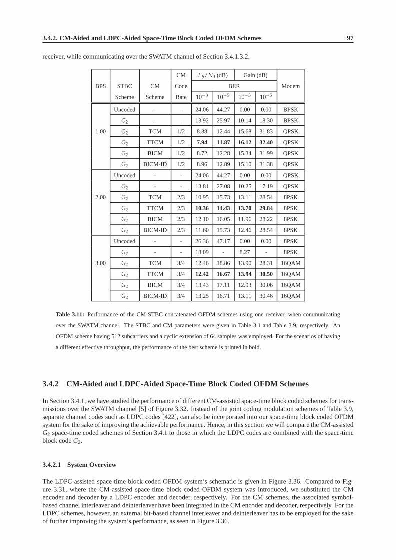
3.4.2. CM-Aided and LDPC-Aided Space-Time Block Coded OFDMSchemes 97
receiver, while communicating over the SWATM channel of Section 3.4.1.3.2.
CM Eb/N0 (dB) Gain (dB)
BPS STBC CM Code BER Modem
Scheme Scheme Rate 10−3 10−5 10−3 10−5
Uncoded - - 24.06 44.27 0.00 0.00 BPSK
G2 - - 13.92 25.97 10.14 18.30 BPSK
1.00 G2 TCM 1/2 8.38 12.44 15.68 31.83 QPSK
G2 TTCM 1/2 7.94 11.87 16.12 32.40 QPSK
G2 BICM 1/2 8.72 12.28 15.34 31.99 QPSK
G2 BICM-ID 1/2 8.96 12.89 15.10 31.38 QPSK
Uncoded - - 24.06 44.27 0.00 0.00 QPSK
G2 - - 13.81 27.08 10.25 17.19 QPSK
2.00 G2 TCM 2/3 10.95 15.73 13.11 28.54 8PSK
G2 TTCM 2/3 10.36 14.43 13.70 29.84 8PSK
G2 BICM 2/3 12.10 16.05 11.96 28.22 8PSK
G2 BICM-ID 2/3 11.60 15.73 12.46 28.54 8PSK
Uncoded - - 26.36 47.17 0.00 0.00 8PSK
G2 - - 18.09 - 8.27 - 8PSK
3.00 G2 TCM 3/4 12.46 18.86 13.90 28.31 16QAM
G2 TTCM 3/4 12.42 16.67 13.94 30.50 16QAM
G2 BICM 3/4 13.43 17.11 12.93 30.06 16QAM
G2 BICM-ID 3/4 13.25 16.71 13.11 30.46 16QAM
Table 3.11: Performance of the CM-STBC concatenated OFDM schemes usingone receiver, when communicating
over the SWATM channel. The STBC and CM parameters were givenin Table 3.1 and Table 3.9, respectively. An
OFDM scheme having 512 subcarriers and a cyclic extension of64 samples was employed. For the scenarios of having
a different effective throughput, the performance of the best scheme is printed in bold.
3.4.2 CM-Aided and LDPC-Aided Space-Time Block Coded OFDM Schemes
In Section 3.4.1, we have studied the performance of different CM-assisted space-time block coded schemes for trans-missions over the SWATM channel [5] of Figure 3.32. Instead of the joint coding modulation schemes of Table 3.9,separate channel codes such as LDPC codes [422], can also be incorporated into our space-time block coded OFDMsystem for the sake of improving the achievable performance. Hence, in this section we will compare the CM-assistedG2 space-time coded schemes of Section 3.4.1 to those in which the LDPC codes are combined with the space-timeblock codeG2.
3.4.2.1 System Overview
The LDPC-assisted space-time block coded OFDM system’s schematic is given in Figure 3.36. Compared to Fig-ure 3.31, where the CM-assisted space-time block coded OFDMsystem was introduced, we substituted the CMencoder and decoder by a LDPC encoder and decoder, respectively. For the CM schemes, the associated symbol-based channel interleaver and deinterleaver have been integrated in the CM encoder and decoder, respectively. For theLDPC schemes, however, an external bit-based channel interleaver and deinterleaver has to be employed for the sakeof further improving the system’s performance, as seen in Figure 3.36.

98 Chapter3. Channel Coding Assisted STBC-OFDM Systems
Source
Sink
LDPC
Encoder
Channel
Interleaver
STBC
Encoder
OFDM
Modulator
Channel
LDPC
Decoder
Channel
Deinterleaver
STBC
Soft Decoder
OFDM
Demodulator
…
…
…
…
Mapper
Soft
Demapper
Figure 3.36: Schematic diagram of the proposed LDPC-assisted space-time block coded OFDM system.
Assisted by Equations (3.31), (3.33), and (3.34), we can calculate the corresponding decoding complexity perbit per iteration for the LDPC and CM schemes, respectively.For the sake of fair comparisons, we have to selectthe appropriate parameters, so that the CM-STBC schemes andthe LDPC-STBC schemes exhibit a similar decodingcomplexity. Specifically, similar to Section 3.4.1.3, the space-time block code was also chosen to be theG2 code inall the LDPC-STBC concatenated OFDM schemes investigated,and thus again the related decoding complexity of theG2 code was neglected in order to simplify our comparisons. Furthermore, the symbol-based codeword length of theLDPC-STBC concatenated schemes was fixed to 1024, which is equal to that of the CM-STBC concatenated schemes.Specifically, the same channel model, namely the SWATM channel of Section 3.4.1.3, and the same OFDM modemhaving 512 subcarriers and a cyclic prefix of 64 samples were employed in this new context.
As mentioned in Section 3.4.1.4, at a specific effective throughput, it was found that the TTCM-assistedG2 codedscheme gave the best performance. Hence we used the TTCM scheme as the representative of the CM family, whilehalf-rate and3
4 -rate LDPC codes were chosen for representing the LDPC code family. As a summary, the parameters ofthe various CM-STBC concatenated OFDM systems are given in Table 3.9, while the parameters of the LDPC-STBCconcatenated OFDM systems are provided in Table 3.12.
STBC LDPC
In. Out. Inter- Symbol-
BPS Code Code Code Column Iter- Bits Bits leaver based Total Modem
Rate Rate Weight ations Block Block Depth Cw. Compl.
Size Size Length
1.00 G2 1 1/2 3 15 1024 2048 2048 1024 1215 QPSK
2.00 G2 1 1/2 3 15 2048 4096 4096 1024 1215 16QAM
3.00 G2 1 3/4 3 10 3072 4096 4096 1024 1530 16QAM
Table 3.12: Parameters of the various LDPC-assisted space-time block coded OFDM schemes. The parameters of the
G2 space-time block code are given in Table 3.1.
3.4.2.2 Simulation Results
In this section we compare the TTCM- and LDPC-assisted space-time block coded OFDM schemes, which are char-acterized in Figure 3.37. All schemes utilized two transmitter antennas for theG2 space-time block code and onereceiver antenna. All simulation results were generated based on the assumptions outlined in Section 3.4.1.3.
As seen from Figure 3.37, the TTCM- and LDPC-assistedG2 coded OFDM schemes have a similar performance.Specifically, when the effective throughput is 1 BPS, the TTCM-assisted scheme performs slightly better than theLDPC-aided candidate system. In the scenario of having an effective throughput of 2 BPS, the former outperformsthe latter again. In this context, however, we may see that the performance gap between the two competing schemes islarger than that in the scenario of having a throughput of 1 BPS. This is because in order to achieve the same effectivethroughput of 2 BPS, the TTCM-aided scheme employs 8PSK modulation in conjunction with set partitioning, whilethe LDPC-aided candidate has to employ the more vulnerable 16QAM gray mapping based constellation, since the

3.5. Chapter Summary 99
stbc-cm_vs_stbc-ldpc_ofdm_rx1_all.gle Fri Aug 1 2003 19:03:47
0 2 4 6 8 10 12 14 16 18 20 22 24 26 28 30Eb/N0 (dB)
10-5
10-4
10-3
10-2
10-1
100
BE
R
STBC+CM v.s STBC+LDPC, OFDM, SWATM
3 BPS: G2(R=1), LDPC(R=3/4), 16QAM3 BPS: G2(R=1), TTCM(R=3/4), 16QAM2 BPS: G2(R=1), LDPC(R=1/2), 16QAM2 BPS: G2(R=1), TTCM(R=2/3), 8PSK1 BPS: G2(R=1), LDPC(R=1/2), QPSK1 BPS: G2(R=1), TTCM(R=1/2), QPSK3 BPS: Uncoded, 8PSK1/2 BPS: Uncoded, BPSK/QPSK
Figure 3.37: The BER versusEb/N0 performance of theG2 space-time block code of Table 3.1 in conjunction withthe TTCM of Table 3.9 or the LDPC codes of Table 3.12 at different effective throughputs using one receiver whencommunicating over the SWATM channel of Figure 3.32. An OFDMscheme having 512 subcarriers and a cyclicextension of 64 samples is employed.
code rate of the TTCM and the LDPC code are23 and 1
2 , respectively. Nonetheless, it is found in Figure 3.37 thatthe two corresponding competitors exhibit a similar performance, when the throughput is increased to 3 BPS. In thiscase, however, the LDPC-aided scheme is marginally superior to the TTCM-aided scheme, when theEb/N0 value isrelatively low, namely below 11dB.
In Figure 3.38, the associated coding gain versus complexity results are provided. The coding gain was defined inSection 3.4.1.5, while the complexity of the CM schemes and LDPC codes can be calculated with the aid of Equa-tions (3.33) and (3.31), respectively. Given the same effective throughput, it is found that the coding gain performanceof the TTCM-aidedG2 schemes surpasses that of the LDPC-aidedG2 schemes, when the affordable complexity ishigher than approximate 500, as observed in Figure 3.38. At alow complexity, namely below a value of about 500,however, the LDPC-aided schemes tend to achieve a higher coding gain than the TTCM-aided schemes at the specificthroughput values considered.
3.4.2.3 Conclusions
In Section 3.4.2.2 the performance of the different TTCM- and LDPC-assistedG2 coded OFDM schemes has beenstudied and compared. As seen from Figure 3.37, the TTCM-assistedG2 scheme gives a better performance than theLDPC-assistedG2 scheme. Furthermore, in the context of the achievable coding gain versus complexity performance,it was found that the TTCM-assisted schemes are capable of achieving higher coding gains in the relatively highcomplexity range, than the LDPC-assisted candidate schemes.
In conclusion, we summarize the achievable performance of the various schemes discussed in Table 3.13.
3.5 Chapter Summary
The state-of-the-art of various transmission schemes based on multiple transmitters and receivers was briefly reviewedin Section 3.1. A simple communication system invoking the space-time block codeG2 was introduced in Sec-tion 3.2.1, leading to further discussions on various otherspace-time block codes. More specifically, Section 3.2.2.1defined the STBC transmission matrix, while the encoding algorithm of theG2 and a range of other space-time blockcodes was given in Sections 3.2.2.2 and 3.2.2.3, respectively. Section 3.2.3 presented the decoding algorithm of the

100 Chapter3. Channel Coding Assisted STBC-OFDM Systems
g2-ttcm_g2-ldpc_comp_vs_cg.gle Wed Aug 6 2003 19:14:29
0 300 600 900 1200 1500 1800 2100 2400 2700 3000Complexity
22
24
26
28
30
32
34
36C
odin
gG
ain
(dB
)Coding Gain v.s Complexity, OFDM, SWATM
3BPS: G2,LDPC(R=3/4),16QAM3BPS: G2,TTCM(R=3/4),16QAM2BPS: G2,LDPC(R=1/2),16QAM2BPS: G2,TTCM(R=2/3),8PSK1BPS: G2,LDPC(R=1/2),QPSK1BPS: G2,TTCM(R=1/2),QPSK
Figure 3.38: Coding gain versus complexity for the TTCM-G2 concatenated and LDPC-G2 concatenated schemes usingone receiver, when communicating over the SWATM channel of Figure 3.32. An OFDM scheme having 512 subcarriersand a cyclic extension of 64 samples is employed. The simulation parameters are given in Tables 3.9 and 3.12.
TTCM LDPC Eb/N0 (dB) Gain (dB)
BPS STBC Code Code BER Modem
Scheme Rate Rate 10−3 10−5 10−3 10−5
Uncoded - - 24.06 44.27 0.00 0.00 BPSK
1.00 G2 - - 13.92 25.97 10.14 18.30 BPSK
G2 1/2 - 7.94 11.87 16.12 32.40 QPSK
G2 - 1/2 8.09 12.04 15.97 32.23 QPSK
Uncoded - - 24.06 44.27 0.00 0.00 QPSK
2.00 G2 - - 13.81 27.08 10.25 17.19 QPSK
G2 2/3 - 10.36 14.43 13.70 29.84 8PSK
G2 - 1/2 11.07 15.10 12.99 29.17 16QAM
Uncoded - - 26.36 47.17 0.00 0.00 8PSK
3.00 G2 - - 18.09 - 8.27 - 8PSK
G2 3/4 - 12.42 16.67 13.94 30.50 16QAM
G2 - 3/4 12.44 17.02 13.92 30.15 16QAM
Table 3.13: Performance of the TTCM- and LDPC-STBC coded concatenated OFDM schemes using one receiver,
when communicating over the SWATM channel of Figure 3.32. The STBC, CM and LDPC parameters were given in
Tables 3.1, 3.9 and 3.12, respectively. An OFDM scheme having 512 subcarriers and a cyclic extension of 64 samples
was employed. For the scenarios of having a different effective throughput, the performance of the best scheme is printed
in bold.
3.5. Chapter Summary 101
space-time block codes considered. More specifically, Section 3.2.3.1 introduced the Maximum Likelihood algorithm,while Section 3.2.3.2 discussed the Maximum-A-Posteriorialgorithm, which enables the STBC decoder to providesoft outputs. Thus various channel codes can be concatenated with the space-time block codes for the sake of im-proving the system’s performance. In Section 3.2.4, the schematic of the proposed system was presented, and someassumptions used in our simulations were outlined.
The performances of the various space-time block codes werestudied and compared in Section 3.2.5. Specifically,in Sections 3.2.5.1 and 3.2.5.2 the performances of different space-time block coded schemes communicating overboth uncorrelated and correlated Rayleigh fading channelswere compared, respectively. It was found that the perfor-mances of the half-rate codesG3 andG4 degraded in comparison to that of the unity-rate codeG2, when the effectivethroughput was increased. The reason is that in order to maintain the same effective throughput, higher-throughputmodulation schemes have to be employed in conjunction with the half-rate codesG3 andG4 which are more vulnerableto errors. This hence degrades the performance of the system. The 3
4 -rate codesH3 andH4 suffer a lower degradationin this case, as their code rate is higher than that of theG3 andG4 codes, therefore a moderate-throughput modulationscheme can be employed. This in turn assists in maintaining the performance advantage achieved by the space-timecodes. Additionally, when the number of receivers is increased, the achievable performance gain of theG3, G4, H3
andH4 codes over theG2 code becomes lower, as seen in Figures 3.4, 3.5, 3.8 and 3.9. This is because much of theattainable diversity gain has already been achieved using the G2 code employing two receivers. Another importantconclusion is that the performances of the space-time codescommunicating over both uncorrelated and correlatedRayleigh fading channels are the same, provided that the effective throughput is the same. The performances of all thespace-time block codes are summarized in Table 3.2 at the endof Section 3.2.6.
The schemes employing space-time block codes in conjunction with channel codes were studied in Section 3.3,which were divided into two parts, namely the performance study of LDPC-aided space-time block codes was pre-sented in Section 3.3.1, while our performance comparisonsbetween LDPC-assisted and TC(2,1,4)-aided STBCschemes were provided in Section 3.3.2.
In Section 3.3.1.1 the LDPC-based system was introduced andthe associated simulation parameters were given.The performances of the LDPC-STBC concatenated schemes were provided in Section 3.3.1.2, including the scenariosof both uncorrelated and correlated Rayleigh fading channels in Section 3.3.1.2.1 and Section 3.3.1.2.2, respectively.The implementation complexity issues of the schemes studied were discussed in Section 3.3.1.3, where the codinggain versus complexity at different effective throughputswas shown in Figures 3.21, 3.22 and 3.23. It was foundthat the LDPC-aided STBC schemes performed significantly better than the STBC-only schemes when communicat-ing over uncorrelated Rayleigh fading channels, while the achievable performance improvement was insignificant,when communicating over correlated Rayleigh fading channels. This is because the attainable performances of theLDPC codes were found to be worse, when comminucating over correlated Rayleigh channels than over uncorrelatedRayleigh channels, unless the LDPC codeword length was sufficiently long enough or a sufficiently long channel in-terleaver was used. The phenomenon of achieving different performances over uncorrelated and correlated Rayleighfading channels was also observed in the context of the LDPC-STBC concatenated system. On the other hand, whenthe number of receiver antennas was increased, the schemes employing a space-time block code of a higher-diversityorder were found to provide an inferior performance, since most of the attainable diversity gain has already beenachieved by the LDPC-aidedG2 coded scheme. It was also found that for transmission over the uncorrelated Rayleighfading channels, when the same modulation scheme was used, alower-rate LDPC code benefited the system morethan a space-time code of a higher-diversity order did. Furthermore, when the same LDPC code was used, a lower-order modulation scheme tended to offer a higher performance improvement, than a space-time block code of a higherdiversity order did. The performance of different LDPC-aided space-time block coded schemes was summarized inTable 3.5, where the half-rate LDPC-coded space-time blockcodeG2 was found to be the best option among all theLDPC-STBC concatenated schemes.
Following Section 3.3.1, where the LDPC-aided space-time coded system was studied, our comparative studybetween LDPC-aided and TC(2,1,4)-assisted STBC schemes transmitting over uncorrelated Rayleigh fading chan-nels was presented in Section 3.3.2. The TC(2,1,4)-aided system was introduced in Section 3.3.2.1, while the as-sociated complexity issues were discussed in Section 3.3.2.2, which was followed by the performance analysis inSection 3.3.2.3. From our coding gain versus complexity performance comparisons, it was concluded that the half-rate TC(2,1,4)-assisted space-time block codeG2 slightly outperforms the LDPC-assisted space-time block codedschemes. However, the LDPC-STBC concatenated schemes may be considered as better design options for complexity-sensitive systems, where the achievable performance does not necessarily have to be the highest possible, since theLDPC-aided schemes are capable of maintaining a lower complexity than the TC(2,1,4)-aided scheme is. In conclu-sion, the performance of the different schemes studied was summarized in Table 3.8.
Furthermore, channel coding assisted space-time block coded single-user OFDM systems were studied in Sec-tion 3.4. This research was divided into two parts. The first part is the investigation of the various CM-assisted

102 Chapter3. Channel Coding Assisted STBC-OFDM Systems
space-time block coded OFDM schemes detailed in Section 3.4.1. The basic OFDM system was introduced inSection 3.4.1.2, followed by the whole system’s overview inSection 3.4.1.3. More specifically, a brief complexityanalysis was provided in Section 3.4.1.3.1, and the introduction of the SWATM channel model was the subject ofSection 3.4.1.3.2. Our simulation results were discussed in Section 3.4.1.4, which were summarized in Table 3.11.The latter part of Section 3.4 focused on the performance comparison of the CM- and LDPC-assisted space-time blockcoded systems considered, which was detailed in Section 3.4.2. The BER versusEb/N0 as well as the coding gainversus complexity performances of the two groups of candidate schemes were compared in Section 3.4.2.2, followedby our conclusions in Section 3.4.2.3, where the results were summarized in Table 3.13.
The family of STBCs is readily applicable to employment in downlink systems, where the multiple transmitterantennas are installed at the BS. However, in the context of uplink systems it is impractical to use high-order STBCs atthe MSs, since the MSs are expected to have a low implementation complexity and thus cannot afford the added costof a high number of transmitter antennas. In the next chapter, Space Division Multiple Access (SDMA) type uplinkmulti-user OFDM systems will be investigated, which invokemultiple receiver antenna elements for supporting amultiplicity of MSs, each of which employs a single transmitter antenna only.

Chapter4Coded Modulation Assisted Multi-UserSDMA-OFDM Using Frequency-DomainSpreading
4.1 Introduction
In recent years Orthogonal Frequency Division Multiplexing (OFDM) [3, 5, 6, 26] has emerged as a successful air-interface technology for both broadcast and Wireless LocalArea Network (WLAN) applications, whilst WidebandCode Division Multiple Access (WCDMA) has emerged as the winning candidate for 3G mobile systems. Our re-search therefore includes an exploration of the performance versus complexity tradeoffs of a generic class of Multi-Carrier Code Division Multiple Access (MC-CDMA) [40] systems, which are capable of supporting the interworkingof existing as well as future broadcast and personal communication systems.
Space Division Multiple Access (SDMA) based OFDM [5,194,441] communication invoking Multi-User Detec-tion (MUD) [442] techniques has recently attracted intensive research interests. In SDMA Multiple-Input Multiple-Output (MIMO) systems the transmitted signals ofL simultaneous uplink mobile users - each equipped with a singletransmitter antenna - are received by theP different receiver antennas of the base station (BS). At theBS the individ-ual users’ signals are separated with the aid of their unique, user-specific spatial signature constituted by their channeltransfer functions or, equivalently, Channel Impulse Responses (CIRs). A variety of MUD schemes, such as the Least-Squares (LS) [5,442,443] and Minimum Mean-Square Error (MMSE) [5,194,198,442,443] detectors, or SuccessiveInterference Cancellation (SIC) [5,194,198,442–444], Parallel Interference Cancellation (PIC) [5,442,444,445] andMaximum Likelihood Detection (MLD) [5,194,198,199,442] schemes may be invoked for the sake of separating thedifferent users at the BS on a per-subcarrier basis. Among these schemes, the MLD arrangement was found to givethe best performance, although this was achieved at the costof a dramatically increased computational complexity,especially in the context of a high number of users and higher-order modulation schemes, such as 16QAM [444]. Bycontrast, MMSE combining exhibits the lowest complexity inthis set of detectors, while suffering from a performanceloss [5,444].
In order to improve the achievable performance by exploiting the multi-path diversity potential offered by wide-band channels, a further technique that is often used in the context of CDMA systems is constituted by the spreading ofthe subcarrier signals over a number of adjacent subcarriers with the aid of orthogonal spreading codes, such as Walsh-Hadamard Transform (WHT) based codes [34]. This technique may also be employed in multi-user SDMA-OFDMsystems in the context of spreading across all or a fraction of the subcarriers [446]. Spreading across all subcarriersusing a single Walsh-Hadamard Transform Spreading (WHTS) [5] code is expected to result in a better averaging ofthe bursty error effects at the cost of a higher WHT complexity.
Furthermore, the achievable performance can be significantly improved, if Forward Error Correction (FEC) schemes,such as for example Turbo Convolutional (TC) codes are incorporated into the SDMA system [5]. Among a number ofFEC schemes, Trellis Coded Modulation (TCM) [359, 437], Turbo TCM (TTCM) [359, 438], Bit-Interleaved CodedModulation (BICM) [359,439] and Iteratively Decoded BICM (BICM-ID) [359,440] have attracted intensive researchinterests, since they are capable of achieving a substantial coding gain without bandwidth expansion.
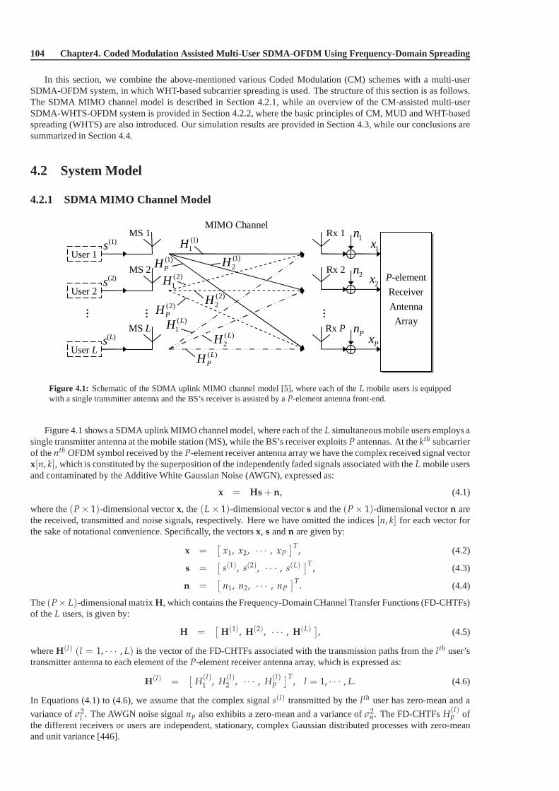
104 Chapter4. Coded Modulation Assisted Multi-User SDMA-OFDM Using Frequency-Domain Spreading
In this section, we combine the above-mentioned various Coded Modulation (CM) schemes with a multi-userSDMA-OFDM system, in which WHT-based subcarrier spreadingis used. The structure of this section is as follows.The SDMA MIMO channel model is described in Section 4.2.1, while an overview of the CM-assisted multi-userSDMA-WHTS-OFDM system is provided in Section 4.2.2, where the basic principles of CM, MUD and WHT-basedspreading (WHTS) are also introduced. Our simulation results are provided in Section 4.3, while our conclusions aresummarized in Section 4.4.
4.2 System Model
4.2.1 SDMA MIMO Channel Model
User 1
User L
User 2
…
(1)s
(2)s
( )Ls
1n
P-element
Receiver
Antenna
Array
2n
Pn
(1)1H
(1)2H(1)
PH(2)1H
(2)2H
(2)PH
( )1
LH( )2
LH( )LPH
……
MIMO Channel
1x
2x
Px
MS 1
MS 2
MS L
Rx 1
Rx 2
Rx P
Figure 4.1: Schematic of the SDMA uplink MIMO channel model [5], where each of theL mobile users is equippedwith a single transmitter antenna and the BS’s receiver is assisted by aP-element antenna front-end.
Figure 4.1 shows a SDMA uplink MIMO channel model, where eachof theL simultaneous mobile users employs asingle transmitter antenna at the mobile station (MS), while the BS’s receiver exploitsP antennas. At thekth subcarrierof thenth OFDM symbol received by theP-element receiver antenna array we have the complex received signal vectorx[n, k], which is constituted by the superposition of the independently faded signals associated with theL mobile usersand contaminated by the Additive White Gaussian Noise (AWGN), expressed as:
x = Hs + n, (4.1)
where the(P × 1)-dimensional vectorx, the(L × 1)-dimensional vectors and the(P × 1)-dimensional vectorn arethe received, transmitted and noise signals, respectively. Here we have omitted the indices[n, k] for each vector forthe sake of notational convenience. Specifically, the vectorsx, s andn are given by:
x =[
x1, x2, · · · , xP
]T, (4.2)
s =[
s(1), s(2), · · · , s(L)]T
, (4.3)
n =[
n1, n2, · · · , nP
]T. (4.4)
The(P× L)-dimensional matrixH, which contains the Frequency-Domain CHannel Transfer Functions (FD-CHTFs)of theL users, is given by:
H =[
H(1), H(2), · · · , H(L)]
, (4.5)
whereH(l) (l = 1, · · · , L) is the vector of the FD-CHTFs associated with the transmission paths from thelth user’stransmitter antenna to each element of theP-element receiver antenna array, which is expressed as:
H(l) =[
H(l)1 , H
(l)2 , · · · , H
(l)P
]T, l = 1, · · · , L. (4.6)
In Equations (4.1) to (4.6), we assume that the complex signal s(l) transmitted by thelth user has zero-mean and a
variance ofσ2l . The AWGN noise signalnp also exhibits a zero-mean and a variance ofσ2
n. The FD-CHTFsH(l)p of
the different receivers or users are independent, stationary, complex Gaussian distributed processes with zero-meanand unit variance [446].
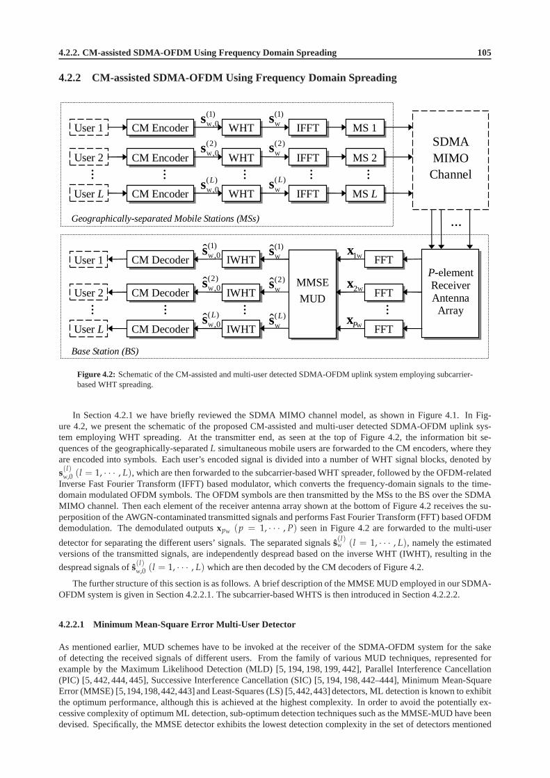
4.2.2. CM-assisted SDMA-OFDM Using Frequency Domain Spreading 105
4.2.2 CM-assisted SDMA-OFDM Using Frequency Domain Spreading
SDMA MIMO Channel
Base Station (BS)
Geographically-separated Mobile Stations (MSs)
P-element Receiver Antenna Array
… … … … …
CM Encoder User 1
User 2
IFFT WHT
CM Encoder WHT IFFT
MS 1
MS 2
W
(1),0s
W
(2),0s
W
(1)s
W
(2)s
User L CM Encoder WHT IFFT MS L W
( ),0
Ls W
( )Ls
…
W1x
W2x
WPx
User 1
User 2
User L
CM Decoder
CM Decoder
IWHT
IWHT
FFT
FFT
W
(1),0s
W
(2),0s
W
( ),0ˆ Ls
W
(1)s
W
(2)s
W
( )ˆ Ls
MMSE
MUD
… … …
CM Decoder IWHT FFT
…
Figure 4.2: Schematic of the CM-assisted and multi-user detected SDMA-OFDM uplink system employing subcarrier-based WHT spreading.
In Section 4.2.1 we have briefly reviewed the SDMA MIMO channel model, as shown in Figure 4.1. In Fig-ure 4.2, we present the schematic of the proposed CM-assisted and multi-user detected SDMA-OFDM uplink sys-tem employing WHT spreading. At the transmitter end, as seenat the top of Figure 4.2, the information bit se-quences of the geographically-separatedL simultaneous mobile users are forwarded to the CM encoders,where theyare encoded into symbols. Each user’s encoded signal is divided into a number of WHT signal blocks, denoted by
s(l)W,0 (l = 1, · · · , L), which are then forwarded to the subcarrier-based WHT spreader, followed by the OFDM-related
Inverse Fast Fourier Transform (IFFT) based modulator, which converts the frequency-domain signals to the time-domain modulated OFDM symbols. The OFDM symbols are then transmitted by the MSs to the BS over the SDMAMIMO channel. Then each element of the receiver antenna array shown at the bottom of Figure 4.2 receives the su-perposition of the AWGN-contaminated transmitted signalsand performs Fast Fourier Transform (FFT) based OFDMdemodulation. The demodulated outputsxpW (p = 1, · · · , P) seen in Figure 4.2 are forwarded to the multi-user
detector for separating the different users’ signals. The separated signalss(l)W (l = 1, · · · , L), namely the estimated
versions of the transmitted signals, are independently despread based on the inverse WHT (IWHT), resulting in the
despread signals ofs(l)W,0 (l = 1, · · · , L) which are then decoded by the CM decoders of Figure 4.2.
The further structure of this section is as follows. A brief description of the MMSE MUD employed in our SDMA-OFDM system is given in Section 4.2.2.1. The subcarrier-based WHTS is then introduced in Section 4.2.2.2.
4.2.2.1 Minimum Mean-Square Error Multi-User Detector
As mentioned earlier, MUD schemes have to be invoked at the receiver of the SDMA-OFDM system for the sakeof detecting the received signals of different users. From the family of various MUD techniques, represented forexample by the Maximum Likelihood Detection (MLD) [5, 194, 198, 199, 442], Parallel Interference Cancellation(PIC) [5, 442, 444, 445], Successive Interference Cancellation (SIC) [5, 194, 198, 442–444], Minimum Mean-SquareError (MMSE) [5,194,198,442,443] and Least-Squares (LS) [5,442,443] detectors, ML detection is known to exhibitthe optimum performance, although this is achieved at the highest complexity. In order to avoid the potentially ex-cessive complexity of optimum ML detection, sub-optimum detection techniques such as the MMSE-MUD have beendevised. Specifically, the MMSE detector exhibits the lowest detection complexity in the set of detectors mentioned

106 Chapter4. Coded Modulation Assisted Multi-User SDMA-OFDM Using Frequency-Domain Spreading
above, although this comes at the cost of a Bit Error Ratio (BER) degradation [5,444].
In the MMSE-based MUD the estimates of the different users’ transmitted signals are generated with the aid ofthe linear MMSE combiner. More specifically, the estimated signal vectors ∈ C(L×1) generated from the transmittedsignals of theL simultaneous users, as shown in Figure 4.2, is obtained by linearly combining the signals received bytheP different receiver antenna elements with the aid of the array weight matrix, as follows [5]:
s = WHMMSEx, (4.7)
where the superscriptH denotes the Hermitian transpose, andWMMSE ∈ C(P×L) is the MMSE-based weight matrix
given by [5]:WMMSE = (HHH + σ2
nI)−1H, (4.8)
while I is the identity matrix andσ2n is the AWGN noise variance.
4.2.2.2 Subcarrier-based Walsh-Hadamard Transform Spreading
In single- and multi-carrier CDMA systems, the employment of orthogonal codes is vital for the sake of supportingmultiple access [34]. In the context of multi-user SDMA-OFDM systems, orthogonal codes may be employed forthe sake of randomizing the wideband channel’s frequency-selective fading, rather than for supporting multiple users,since the multiple users are supported with the aid of the SDMA-OFDM system employing aP-element antenna arrayand appropriate multi-user detection techniques.
A prominent class of orthogonal codes often used in CDMA systems is the family of orthogonal Walsh codes [34],which are particularly attractive, since the operation of spreading with the aid of these codes can be implemented inform of a ‘fast’ transform, which takes advantage of the codes’ recursive structure, similarly to the FFT [5].
Let us now provide a deeper insight into the operation of the subcarrier-based WHTS [5]. During every OFDMsymbol period prior to transmission of the independent usersignals, theK data samples associated with the subcarriers,whereK is the FFT length, may be spread with the aid of the WHT having ablock size ofK. This is achieved by
left-multiplying the WHT signal blocks(l)W,0 (l = 1, · · · , L) of Figure 4.2 with theK-order WHT matrixUWHTK for
each user separately:
s(l)W = UWHTK
s(l)W,0, l = 1, · · · , L, (4.9)
wheres(l)W is thelth user’s spread signal block, andUWHTK
is given in a recursive form as:
UWHTK =1√2
[
1 · UWHTK/21 · UWHTK/2
1 · UWHTK/2−1 · UWHTK/2
]
, (4.10)
while the lowest-order WHT unitary matrix is defined by:
UWHT2 =1√2
[
1 11 −1
]
. (4.11)
When the WHT block size is long, for example identical to the FFT length ofK = 512, the computational complexityimposed by the length-K WHTS may be very high. Therefore a more practical solution isto further divide theKsamples intoK/MWHT number of interleaved blocks, each of which has a block size of MWHT < K. Specifically, theith
WHT block is constituted by the samples selected from the subcarriers having the indices [5,446]:
j = i + rK
MWHT
, 0 ≤ i ≤ K
MWHT
− 1, 0 ≤ r ≤ MWHT − 1, (4.12)
wherei is the index of the WHT blocks within the same OFDM symbol. In Figure 4.3 we illustrate the operation ofthe subcarrier-based WHTS, where the number of OFDM subcarriers is 512 and the WHT block size is 32. Thereforein each OFDM symbol we have512/32 = 16 frequency-domain interleaved WHT blocks. At the top of Figure 4.3 anOFDM symbol is shown with the subcarriers’ indices displayed, while the bottom illustration of the figure shows theWHT blocks generated, which contain subcarriers of the specified indices, as given by Equation (4.12). As Figure 4.3shows, for example, the signal sample carried by the second (r = 1) slot within the WHT block of indexi = 0 isselected from the subcarrier of indexj = 16 within the original OFDM symbol. After the WHT blocks are formed,the WHTS is then invoked with the aid of the length-MWHT WHT matrix given in Equation (4.10).

4.3. Simulation Results 107
WHT block 0 WHT block 1
subcarrier index j
32
OFDM symbol
32
0 1 16
0 16 1 17
32 ... ...
... ...
17 33 ...
... 32 33
Figure 4.3: Example of the subcarrier-based WHT blocks’ generation using a WHT block size of 32, where the totalnumber of OFDM subcarriers is 512.
At the BS receiver seen in Figure 4.2, the despreading operation follows the inverse procedure of that portrayed inFigure 4.3, which is invoked independently for the separated signal of each user. More specifically, we have:
s(l)W,0 = UWHTK s
(l)W , l = 1, · · · , L, (4.13)
wheres(l)W,0 and s
(l)W are the estimated version ofs
(l)W,0 ands
(l)W , respectively, whiles(l)
W is achieved by applying Equa-tion (4.7) at each subcarrier of every length-MWHT WHT block. Upon employing the WHTS technique, the detrimentaleffects imposed on the system’s average BER performance by the specific subcarriers corrupted by deep frequency-domain channel fades can be potentially improved, since theeffects of the fades are spread over the entire WHT block.Hence the receiver has a high chance of recovering the impaired transmitted signals of the badly affected subcarriers.
4.3 Simulation Results
In this section, we characterize the performance of the proposed CM-assisted MMSE-SDMA-OFDM schemes inconjunction with WHTS. The channel is assumed to be OFDM-symbol-invariant, implying that the taps of the impulseresponse are assumed to be constant for the duration of one OFDM symbol, but they are faded at the beginning of eachsymbol [4]. Each user’s associated transmit power or signalvariance is assumed to be the same and normalized tounity, while the complex-valued fading envelope of the different users’ signal is assumed to be uncorrelated. For thesake of simplifying the experimental conditions, the channel’s frequency-domain transfer function is assumed to beperfectly known in all simulations. Nonetheless, these performance trends are expected to remain unchanged in caseof imperfect channel estimation, in particular, when the turbo-style PIC aided Recursive Least-Squares (RLS) channelestimators of Chapter 16 in reference [5] are used. This may be made plausible by noting that turbo-style iterativedetection techniques have been reported to be capable of achieving a virtually indistinguishable performance from theidealistic system using perfect channel estimation [5,359].
4.3.1 MMSE-SDMA-OFDM Using WHTS
We commence by considering a multi-user SDMA-OFDM system operating without the assistance of CM commu-nicating over the Short Wireless Asynchronous Transfer Mode (SWATM) channel of [4]. The impulse response ofthe three-tap SWATM channel was given in Figure 3.32, while the specific channel parameters used were given inTable 3.10. Each of the three paths experiences independentRayleigh fading having the same normalized Dopplerfrequency off ′d = 1.235× 10⁻⁵. A total of 512 subcarriers and a cyclic prefix of 64 samples were used for the OFDMmodem.
Figure 4.4 compares the BER versusEb/N0 performance of the MMSE-SDMA-OFDM system equipped with tworeceiver antenna elements, while supporting one or two users both with and without WHTS, respectively. Furthermore,the performance of the unprotected single-user BPSK schemecommunicating over an AWGN channel is also providedfor reference. As expected, the WHTS-assisted schemes perform better than their non-spread counterparts, both for

108 Chapter4. Coded Modulation Assisted Multi-User SDMA-OFDM Using Frequency-Domain Spreading
uxr2_mmse_wht32_4qam_swatm.gle Sat Jan 29 2005 22:11:40
0 2 4 6 8 10 12 14 16 18 20 22 24 26 28 30Eb/N0 (dB)
10-5
10-4
10-3
10-2
10-1
100
BE
R
WHTS-MMSE-SDMA-OFDM, Lx/P2, 4QAM, SWATM
L2/P2, WHTSL2/P2L1/P2, WHTSL1/P2L1/P1 (AWGN)
Figure 4.4: BER versusEb/N0 performance of theWHTS-assisted MMSE-SDMA-OFDM system employing a4QAM scheme for transmission over theSWATM channel, whereL=1, 2 users are supported with the aid ofP=2receiver antenna elements. The WHT block size used is32.
one and two users. It is also beneficial to view the subcarrierBERs as a function of both the subcarrier index and theEb/N0, which was portrayed in Figure 4.5 for the SDMA-OFDM system equipped with two BS receiver antennasfor supporting two users. The subcarrier BER is defined as theBER averaged over a specific subcarrier of all theconsecutive OFDM symbols transmitted by the users. It was found that at a specificEb/N0 value, the subcarrier BERcurves shown at the top of Figures 4.5, exhibit undulations across the frequency domain owing to deep channel fadesat certain subcarriers, which could be potentially eliminated with the aid of WHTS, as observed at the bottom of thefigure. This suggests that the system’s average BER performance can be potentially improved by using WHTS, sincethe bursty subcarrier errors can be effectively spread across the subcarriers of the entire WHT block.
4.3.2 CM- and WHTS-assisted MMSE-SDMA-OFDM
Similarly to the previous sections, let us first investigatethe SDMA-OFDM system’s performance while communicat-ing over the SWATM channel [4].
4.3.2.1 Performance Over the SWATM Channel
For the various CM schemes used, we select the parameters so that all schemes have the same effective throughputand the same number of decoding states, hence have a similar decoding complexity. More specifically, the codememoryν is fixed to 6 for the non-iterative TCM and BICM schemes, so that the number of decoding states becomesS = 2ν = 64. For the iterative TTCM and BICM-ID schemes, however,ν is fixed to 3, while the number of iterationsfor these schemes is set to 4 and 8, respectively. Hence the total number of trellis states is23 · 4 · 2 = 64 for TTCM and23 · 8 · 1 = 64 for BICM-ID, since there are two 8-state decoders, which areinvoked in four iterations in the scenario ofTTCM, while only one 8-state decoder is employed in the context of BICM-ID. The generator polynomials expressedin octal format for TCM, TTCM, BICM and BICM-ID are[117 26], [13 6], [133 171] and[15 17], respectively.The parameters of the various CM schemes used are summarizedin Table 4.1.
4.3.2.1.1 Two Receiver Antenna Elements
In Section 4.3.1 the beneficial effects of WHTS on the MMSE-SDMA-OFDM system’s performance have beendemonstrated. Let us now combine the various CM schemes considered with the multi-user MMSE-SDMA-OFDM
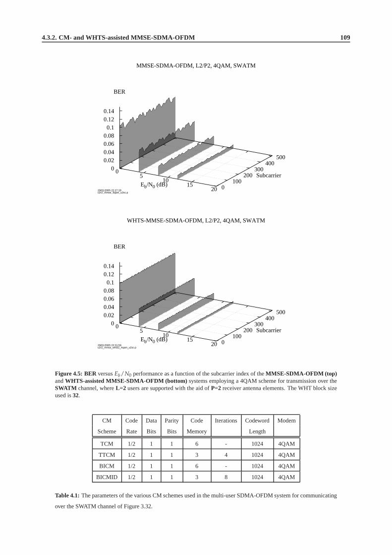
4.3.2. CM- and WHTS-assisted MMSE-SDMA-OFDM 109
MMSE-SDMA-OFDM, L2/P2, 4QAM, SWATM
29/01/2005 22:27:19u2r2_mmse_4qam_u2sc.p
0 5
10 15
20Eb/N0 (dB) 0
100 200
300 400
500
Subcarrier 0
0.02 0.04 0.06 0.08 0.1
0.12 0.14
BER
WHTS-MMSE-SDMA-OFDM, L2/P2, 4QAM, SWATM
29/01/2005 22:31:59u2r2_mmse_wht32_4qam_u2sc.p
0 5
10 15
20Eb/N0 (dB) 0
100 200
300 400
500
Subcarrier 0
0.02 0.04 0.06 0.08 0.1
0.12 0.14
BER
Figure 4.5: BER versusEb/N0 performance as a function of the subcarrier index of theMMSE-SDMA-OFDM (top)andWHTS-assisted MMSE-SDMA-OFDM (bottom) systems employing a 4QAM scheme for transmission over theSWATM channel, whereL=2 users are supported with the aid ofP=2 receiver antenna elements. The WHT block sizeused is32.
CM Code Data Parity Code Iterations Codeword Modem
Scheme Rate Bits Bits Memory Length
TCM 1/2 1 1 6 - 1024 4QAM
TTCM 1/2 1 1 3 4 1024 4QAM
BICM 1/2 1 1 6 - 1024 4QAM
BICMID 1/2 1 1 3 8 1024 4QAM
Table 4.1: The parameters of the various CM schemes used in the multi-user SDMA-OFDM system for communicating
over the SWATM channel of Figure 3.32.

110 Chapter4. Coded Modulation Assisted Multi-User SDMA-OFDM Using Frequency-Domain Spreading
system. The corresponding simulation results are portrayed in Figure 4.6, where the top and bottom of the figureillustrate the BER and CodeWord Error Ratio (CWER) versusEb/N0 performance of the proposed CM-MMSE-SDMA-OFDM schemes, respectively.
Here we define the user load of anL-user andP-receiver SDMA-OFDM system as:
αP =L
P, (4.14)
which assumes a value of unity in case of full user load, when the number of users is equal to the number of receiverantenna elements. The simulation results generated in the context ofα2 = 0.5 andα2 = 1 are plotted at the leftand right side of Figure 4.6, respectively. The BER performance of the 32-state TC code assisted MMSE-SDMA-OFDM [5] system is also portrayed as a reference. Furthermore, the performance of the unprotected 4QAM SDMA-OFDM system and that of the single-user BPSK scheme communicating over an AWGN channel is also provided as abenchmarker. As observed in Figure 4.6, the TC-assisted arrangement and the various CM-assisted schemes provide asimilar BER performance in both scenarios. As expected, allthe FEC-aided schemes perform significantly better thantheir unprotected counterparts in the BER performance investigations. Furthermore, the TTCM-aided scheme is foundto give the best CWER performance from the set of all CM-aidedschemes in both the half-loaded and fully-loadedscenarios, whereα2 is equal to 0.5 and 1, respectively. This suggests that more transmission errors can be eliminatedby TTCM than by the other three CM schemes, although the bursterrors inflicted by deep frequency-domain channelfades cannot be recovered completely. However, this effectmay be potentially mitigated by employing WHTS, asdiscussed in Section 4.2.2.2.
As expected, for each of the schemes evaluated, we may noticethat the performance achieved in the contextof α2 = 0.5, is better than that attained, when we haveα2 = 1. This phenomenon may be explained as follows.SinceP receiver antenna elements are invoked at the BS, there areP uplink paths for each MS user having onetransmitter antenna. Hence the achievable spatial diversity order provided by theP paths remains the same for eachuser, regardless of the total number of simultaneous users supported. However, when the user load is lower, i.e. thenumber of users supported is lower, the MMSE combiner will benefit from a higher degree of freedom in terms of thechoice of the array weights optimized for differentiating the different users’ transmitted signal, and thus the systembecomes more efficient in terms of suppressing the reduced Multi-User Interference (MUI).
In Figure 4.7, we provide the subcarrier based BER versusEb/N0 performance of the TTCM-assisted MMSE-SDMA-OFDM system in the context of two users and two receiverantenna elements. Comparing Figure 4.5 toFigure 4.7, where the beneficial effects of WHTS have been characterized, we may notice that the achievable perfor-mance improvement attained by TTCM, or more generally by theCM schemes, is typically higher than that achievedby WHTS.
Having discussed the beneficial effects of WHTS and those of CM on the SDMA-OFDM system, as described inSection 4.3.1 and earlier in this section, respectively, wenow combine the MMSE-SDMA-OFDM system with CMand WHTS. The corresponding simulation results are portrayed in Figure 4.8, where the left and right side of thefigure illustrate the scenarios ofα2 = 0.5 andα2 = 1, while the top and bottom of the figure shows the BER andCWER performance, respectively. Again, the TTCM-aided scheme was found to give the best CWER performanceamong all the CM-aided schemes considered. Comparison of Figure 4.6 and Figure 4.8 shows that in the CM-aidedMMSE-SDMA-OFDM system the employment of WHTS having a blocksize of 32 only insignificantly improves thesystem’s BER and CWER performance, since most of the achievable diversity gain may have already been achieved byusing the CM schemes. However, the employment of WHTS has thepotential of further enhancing the CM-SDMA-OFDM system’s performance in highly-dispersive propagation environments, an issue which will be further discussedin Section 4.3.2.2.
Furthermore, if a longer CM codeword length is used, the system’s performance can be further improved at thecost of a higher computational complexity. The effects of different CM codeword lengths can be seen in Figure 4.9. Asexpected, when a higher codeword length is employed, the system’s performance becomes better, since a longer CMcodeword is capable of better averaging the bursty error effects. However this performance improvement is achievedat a substantially higher complexity. For examples of the associated complexity issues, the interested reader is referredto Chapter 9 of [359].
4.3.2.1.2 Four Receiver Antenna Elements
In Section 4.3.2.1.1, we have compared the various CM- and WHTS-aided schemes in the context of one or two usersand two receiver antenna elements. In this section, we investigate a higher-order spatial diversity assisted scenariobyincreasing the number of receiver antenna elements, and thus supporting a higher number of simultaneous users.

4.3.2. CM- and WHTS-assisted MMSE-SDMA-OFDM 111
d_uxr2_mmse_cm_4qam_swatm.gle Sat Jan 29 2005 22:41:43
0 2 4 6 8 10 12 14 16 18 20Eb/N0 (dB)
10-5
10-4
10-3
10-2
10-1
100
BE
R
CM-MMSE-SDMA-OFDM, L1/P2, 4QAM, SWATM
BICM-IDBICMTTCMTCMTC(No FEC)(AWGN)
0 2 4 6 8 10 12 14 16 18 20Eb/N0 (dB)
10-5
10-4
10-3
10-2
10-1
100
BE
R
CM-MMSE-SDMA-OFDM, L2/P2, 4QAM, SWATM
BICM-IDBICMTTCMTCMTC(No FEC)(AWGN)
d_uxr2_mmse_cm_4qam_swatm_cwer.gle Sat Jan 29 2005 22:44:15
0 2 4 6 8 10 12 14 16 18 20Eb/N0 (dB)
10-3
2
5
10-2
2
5
10-1
2
5
100
CW
ER
CM-MMSE-SDMA-OFDM, L1/P2, 4QAM, SWATM
BICM-IDBICMTTCMTCM
0 2 4 6 8 10 12 14 16 18 20Eb/N0 (dB)
10-3
2
5
10-2
2
5
10-1
2
5
100
CW
ER
CM-MMSE-SDMA-OFDM, L2/P2, 4QAM, SWATM
BICM-IDBICMTTCMTCM
Figure 4.6: BER (top) andCWER (bottom) versusEb/N0 performance of theCM-assisted MMSE-SDMA-OFDMsystem employing a 4QAM scheme for transmission over theSWATM channel, whereL=1 (left) or L=2 (right) usersare supported with the aid ofP=2 receiver antenna elements. The CM parameters are given in Table 4.1. The CMcodeword length is1024symbols. The BER performance of the same 4QAM MMSE-SDMA-OFDM system assistedby the half-rate TC code [5] (the curves with the legend of2) is also provided for reference.

112 Chapter4. Coded Modulation Assisted Multi-User SDMA-OFDM Using Frequency-Domain Spreading
TTCM-MMSE-SDMA-OFDM, L2/P2, 4QAM, SWATM
29/01/2005 22:35:55u2r2_mmse_ttcm_4qam_u1sc.p
0 5
10 15
20Eb/N0 (dB) 0
100 200
300 400
500
Subcarrier 0
0.02 0.04 0.06 0.08 0.1
0.12 0.14
BER
Figure 4.7: BER versusEb/N0 performance as a function of the subcarrier index of theTTCM-assisted MMSE-SDMA-OFDM system employing a 4QAM scheme for transmission over theSWATM channel, whereL=2 users aresupported with the aid ofP=2 receiver antenna elements. The TTCM codeword length is1024symbols.
Figures 4.10 and 4.11 show the BER and CWER performance achieved by the CM- and WHTS-aided MMSE-SDMA-OFDM schemes in the scenario, where there are four receivers supporting a maximum number of four users.The BER performance of the 32-state TC code assisted MMSE-SDMA-OFDM [5] system is also provided as a refer-ence. As seen in Figure 4.10, similar to the two-receiver scenario of Figure 4.8, the TC-assisted arrangement and thevarious CM-aided schemes achieve a similar BER performanceat a specific user load. However, again, the TTCM-aided scheme stands out of all CM-aided schemes by attaininga better CWER performance.
Furthermore, comparing Figure 4.8 to Figure 4.10, where there are two receivers supporting a maximum of twousers, we find that at the same user load level, for example atα4 = α2 = 0.5 or α4 = α2 = 1.0, the Eb/N0
performance achieved by the four-receiver system is approximately 4.5dB better than that of the two-receiver system,provided that the same CM-assisted scheme is used. This is because, when the number of the BS receiver antennaelements is increased, the SDMA-MIMO system becomes capable of providing a higher diversity gain, which may beexpected to improve the system’s performance for each user.
4.3.2.2 Performance Over the COST207 HT Channel
In this section, we will investigate the performance of the CM- and WHTS-assisted MMSE-SDMA-OFDM schemes,while communicating over a more dispersive channel, namelyover the 12-path COST207 [447] Hilly Terrain (HT)channel. The impulse response of the channel model is portrayed in Figure 4.12, while the specific channel parametersare given in Table 4.2. Each of the twelve paths experiences independent Rayleigh fading having the same normalizedDoppler frequency off ′d = 1.0× 10⁻⁵. Compared to the 512-subcarrier OFDM modem used for communication overthe SWATM channel investigated in Section 4.3.2.1, we now employ a higher number of 2048 subcarriers and a cyclicprefix of 256, since the maximum path delay of the COST207 HT channel is longer than that of the SWATM channel,hence it requires a longer cyclic prefix for combatting the effects of Inter-Symbol Interference (ISI) [5,26].
In Sections 4.3.2.2.1 and 4.3.2.2.2, we will compare the corresponding performance of the various CM- andWHTS-assisted MMSE-SDMA-OFDM schemes, when communicating over the COST207 HT channel. The pa-rameters of the CM schemes used are summarized in Table 4.3.
4.3.2.2.1 Two Receiver Antenna Elements
We present the BER and CWER performance of the CM-assisted MMSE-SDMA-OFDM system dispensing withWHTS for transmission over the COST207 HT channel at the top of Figures 4.13 and 4.14, respectively. Two receiver

4.3.2. CM- and WHTS-assisted MMSE-SDMA-OFDM 113
d_uxr2_mmse_wht32_cm_4qam_swatm.gle Sat Jan 29 2005 22:48:17
0 2 4 6 8 10 12 14 16 18 20Eb/N0 (dB)
10-5
10-4
10-3
10-2
10-1
100
BE
R
CM-WHTS-MMSE-SDMA-OFDM, L1/P2, 4QAM, SWATM
BICM-ID, WHTSBICM, WHTSTTCM, WHTSTCM, WHTSTC(No FEC)(AWGN)
0 2 4 6 8 10 12 14 16 18 20Eb/N0 (dB)
10-5
10-4
10-3
10-2
10-1
100
BE
R
CM-WHTS-MMSE-SDMA-OFDM, L2/P2, 4QAM, SWATM
BICM-ID, WHTSBICM, WHTSTTCM, WHTSTCM, WHTSTC(No FEC)(AWGN)
d_uxr2_mmse_wht32_cm_4qam_swatm_cwer.gle Sat Jan 29 2005 22:49:13
0 2 4 6 8 10 12 14 16 18 20Eb/N0 (dB)
10-3
2
5
10-2
2
5
10-1
2
5
100
CW
ER
CM-WHTS-MMSE-SDMA-OFDM, L1/P2, 4QAM, SWATM
BICM-ID, WHTSBICM, WHTSTTCM, WHTSTCM, WHTS
0 2 4 6 8 10 12 14 16 18 20Eb/N0 (dB)
10-3
2
5
10-2
2
5
10-1
2
5
100
CW
ER
CM-WHTS-MMSE-SDMA-OFDM, L2/P2, 4QAM, SWATM
BICM-ID, WHTSBICM, WHTSTTCM, WHTSTCM, WHTS
Figure 4.8: BER (top) andCWER (bottom) versusEb/N0 performance of theCM- and WHTS-assisted MMSE-SDMA-OFDM system employing a 4QAM scheme for transmission over theSWATM channel, whereL=1 (left) orL=2 (right) users are supported with the aid ofP=2 receiver antenna elements. The CM parameters are given inTable 4.1. The CM codeword length is1024symbols and the WHT block size used is32. The BER performance of the4QAM MMSE-SDMA-OFDM system assisted by the half-rate TC code [5] (the curves with the legend of2) is alsoprovided for reference.
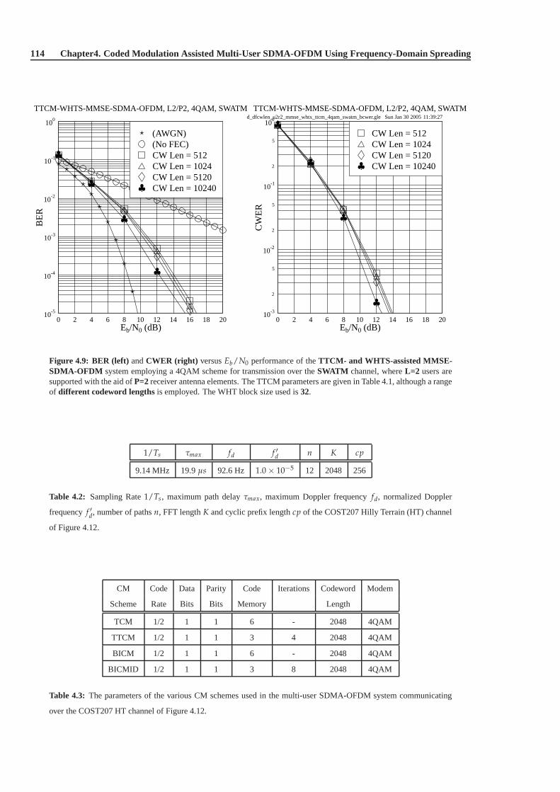
114 Chapter4. Coded Modulation Assisted Multi-User SDMA-OFDM Using Frequency-Domain Spreading
d_dfcwlen_u2r2_mmse_whtx_ttcm_4qam_swatm_bcwer.gle Sun Jan 30 2005 11:39:27
0 2 4 6 8 10 12 14 16 18 20Eb/N0 (dB)
10-5
10-4
10-3
10-2
10-1
100
BE
R
TTCM-WHTS-MMSE-SDMA-OFDM, L2/P2, 4QAM, SWATM
CW Len = 10240CW Len = 5120CW Len = 1024CW Len = 512(No FEC)(AWGN)
0 2 4 6 8 10 12 14 16 18 20Eb/N0 (dB)
10-3
2
5
10-2
2
5
10-1
2
5
100
CW
ER
TTCM-WHTS-MMSE-SDMA-OFDM, L2/P2, 4QAM, SWATM
CW Len = 10240CW Len = 5120CW Len = 1024CW Len = 512
Figure 4.9: BER (left) andCWER (right) versusEb/N0 performance of theTTCM- and WHTS-assisted MMSE-SDMA-OFDM system employing a 4QAM scheme for transmission over theSWATM channel, whereL=2 users aresupported with the aid ofP=2receiver antenna elements. The TTCM parameters are given inTable 4.1, although a rangeof different codeword lengthsis employed. The WHT block size used is32.
1/Ts τmax fd f ′d n K cp
9.14 MHz 19.9µs 92.6 Hz 1.0 × 10⁻⁵ 12 2048 256
Table 4.2: Sampling Rate1/Ts, maximum path delayτmax, maximum Doppler frequencyfd, normalized Doppler
frequencyf ′d, number of pathsn, FFT lengthK and cyclic prefix lengthcp of the COST207 Hilly Terrain (HT) channel
of Figure 4.12.
CM Code Data Parity Code Iterations Codeword Modem
Scheme Rate Bits Bits Memory Length
TCM 1/2 1 1 6 - 2048 4QAM
TTCM 1/2 1 1 3 4 2048 4QAM
BICM 1/2 1 1 6 - 2048 4QAM
BICMID 1/2 1 1 3 8 2048 4QAM
Table 4.3: The parameters of the various CM schemes used in the multi-user SDMA-OFDM system communicating
over the COST207 HT channel of Figure 4.12.

4.3.2. CM- and WHTS-assisted MMSE-SDMA-OFDM 115
d_u12r4_mmse_wht32_cm_4qam_swatm.gle Sat Jan 29 2005 22:54:37
0 2 4 6 8 10 12 14 16 18 20Eb/N0 (dB)
10-5
10-4
10-3
10-2
10-1
100
BE
R
CM-WHTS-MMSE-SDMA-OFDM, L1/P4, 4QAM, SWATM
BICM-ID, WHTSBICM, WHTSTTCM, WHTSTCM, WHTSTC(No FEC)(AWGN)
0 2 4 6 8 10 12 14 16 18 20Eb/N0 (dB)
10-5
10-4
10-3
10-2
10-1
100
BE
R
CM-WHTS-MMSE-SDMA-OFDM, L2/P4, 4QAM, SWATM
BICM-ID, WHTSBICM, WHTSTTCM, WHTSTCM, WHTSTC(No FEC)(AWGN)
d_u34r4_mmse_wht32_cm_4qam_swatm.gle Sat Jan 29 2005 22:55:48
0 2 4 6 8 10 12 14 16 18 20Eb/N0 (dB)
10-5
10-4
10-3
10-2
10-1
100
BE
R
CM-WHTS-MMSE-SDMA-OFDM, L3/P4, 4QAM, SWATM
BICM-ID, WHTSBICM, WHTSTTCM, WHTSTCM, WHTSTC(No FEC)(AWGN)
0 2 4 6 8 10 12 14 16 18 20Eb/N0 (dB)
10-5
10-4
10-3
10-2
10-1
100
BE
R
CM-WHTS-MMSE-SDMA-OFDM, L4/P4, 4QAM, SWATM
BICM-ID, WHTSBICM, WHTSTTCM, WHTSTCM, WHTSTC(No FEC)(AWGN)
Figure 4.10: BER versusEb/N0 performance of theCM- and WHTS-assisted MMSE-SDMA-OFDM system em-ploying a 4QAM scheme for transmission over theSWATM channel, whereL=1 (top left) , L=2 (top right) , L=3(bottom left) or L=4 (bottom right) users are supported with the aid ofP=4 receiver antenna elements. The CM pa-rameters are given in Table 4.1. The CM codeword length is1024symbols and the WHT block size used is32. TheBER performance of the 4QAM MMSE-SDMA-OFDM system assistedby the half-rate TC code [5] (the curves withthe legend of2) is also provided for reference.
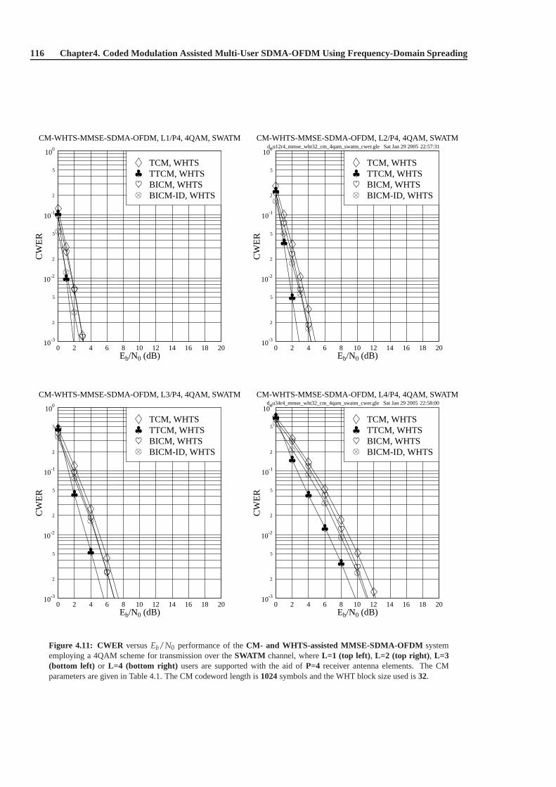
116 Chapter4. Coded Modulation Assisted Multi-User SDMA-OFDM Using Frequency-Domain Spreading
d_u12r4_mmse_wht32_cm_4qam_swatm_cwer.gle Sat Jan 29 2005 22:57:31
0 2 4 6 8 10 12 14 16 18 20Eb/N0 (dB)
10-3
2
5
10-2
2
5
10-1
2
5
100
CW
ER
CM-WHTS-MMSE-SDMA-OFDM, L1/P4, 4QAM, SWATM
BICM-ID, WHTSBICM, WHTSTTCM, WHTSTCM, WHTS
0 2 4 6 8 10 12 14 16 18 20Eb/N0 (dB)
10-3
2
5
10-2
2
5
10-1
2
5
100
CW
ER
CM-WHTS-MMSE-SDMA-OFDM, L2/P4, 4QAM, SWATM
BICM-ID, WHTSBICM, WHTSTTCM, WHTSTCM, WHTS
d_u34r4_mmse_wht32_cm_4qam_swatm_cwer.gle Sat Jan 29 2005 22:58:00
0 2 4 6 8 10 12 14 16 18 20Eb/N0 (dB)
10-3
2
5
10-2
2
5
10-1
2
5
100
CW
ER
CM-WHTS-MMSE-SDMA-OFDM, L3/P4, 4QAM, SWATM
BICM-ID, WHTSBICM, WHTSTTCM, WHTSTCM, WHTS
0 2 4 6 8 10 12 14 16 18 20Eb/N0 (dB)
10-3
2
5
10-2
2
5
10-1
2
5
100
CW
ER
CM-WHTS-MMSE-SDMA-OFDM, L4/P4, 4QAM, SWATM
BICM-ID, WHTSBICM, WHTSTTCM, WHTSTCM, WHTS
Figure 4.11: CWER versusEb/N0 performance of theCM- and WHTS-assisted MMSE-SDMA-OFDM systememploying a 4QAM scheme for transmission over theSWATM channel, whereL=1 (top left) , L=2 (top right) , L=3(bottom left) or L=4 (bottom right) users are supported with the aid ofP=4 receiver antenna elements. The CMparameters are given in Table 4.1. The CM codeword length is1024symbols and the WHT block size used is32.

4.3.2. CM- and WHTS-assisted MMSE-SDMA-OFDM 117
cost207ht_channel.gle Wed Nov 26 2003 17:29:19
0 5 10 15 20 25 30Time Delay [ s]
0.0
0.1
0.2
0.3
0.4
0.5
0.6
0.7
0.8
0.9
1.0
Am
plitu
deThe COST207 Hilly Terrain Channel
Figure 4.12: COST207 Hilly Terrain (HT) channel impulse response. The corresponding parameters of the channel aresummarized in Table 4.2.
antenna elements are employed for supporting a maximum of two users. The simulation results show that the TTCM-aided scheme constitutes the best design option in terms of both the BER and CWER, attaining a coding gain rangingfrom 2dB to 4dB over the other three CM-aided schemes at the BER of 10−5 without the assistance of WHTS.Furthermore, when WHTS is incorporated into the CM-MMSE-SDMA-OFDM system, as seen in the bottom ofFigures 4.13 and 4.14, a further usefulEb/N0 gain is achieved by most of the four schemes, especially by the TCM-aided arrangement. However, recall that in Section 4.3.2.1where the SWATM channel was employed, the additionalEb/N0 gain achieved by spreading in the context of the various CM- and WHTS-assisted schemes was rather modest.This result may suggest that in highly dispersive environments, such as that characterized by the 12-path COST207HT channel, the channel-coded SDMA-OFDM system’s performance may be further improved by employing WHTS.This spreading-inducedEb/N0 gain was achieved, because the detrimental effects imposedon the system’s averageBER performance by the deeply-faded subcarriers has been spread over the entire WHT block, and these randomizedor dispersed channel errors may be more readily corrected bythe CM decoders.
It transpires from Figures 4.13 and 4.14 that the four CM-aided schemes communicating over the COST207 HTchannel attain a different performance. This observation is different from what was noted in Figures 4.6 and 4.8,where the performance of the various CM-aided schemes communicating over the SWATM channel was more similar.The reason for this phenomenon is that the amplitude variation of the FD-CHTFs becomes both more frequent andmore dramatic, when the channel exhibits a longer path delay[359]. Since the COST207 HT channel’s maximum pathdelay is 19.9µs, which is significantly longer than the 48.9ns maximum dispersion of the SWATM channel, the fadesoccur more frequently in the FD-CHTF of the COST207 HT channel, as indicated by Figure 4.15. Apparently, in theCOST207 HT channel displayed at the left hand side of Figure 4.15, the frequency domain separation between theneighbouring fades is proportionately lower than that in the SWATM channel shown at the right side of Figure 4.15.This characteristic will result in more uniformly distributed corrupted subcarrier symbols which can be more readilycorrected by the channel codes. More specifically, when a deep fade occurs in the FD-CHTF of the SWATM channel, anumber of consecutive subcarriers which are located in the corresponding faded block of subcarriers may be seriously

118 Chapter4. Coded Modulation Assisted Multi-User SDMA-OFDM Using Frequency-Domain Spreading
d_uxr2_mmse_cm_4qam_cost207ht.gle Sun Jan 30 2005 11:07:52
0 1 2 3 4 5 6 7 8 9 10Eb/N0 (dB)
10-5
10-4
10-3
10-2
10-1
100
BE
R
CM-MMSE-SDMA-OFDM, L1/P2, 4QAM, COST207 HT
BICM-IDBICMTTCMTCM(No FEC)(AWGN)
0 1 2 3 4 5 6 7 8 9 10Eb/N0 (dB)
10-5
10-4
10-3
10-2
10-1
100
BE
R
CM-MMSE-SDMA-OFDM, L2/P2, 4QAM, COST207 HT
BICM-IDBICMTTCMTCM(No FEC)(AWGN)
d_uxr2_mmse_wht32_cm_4qam_cost207ht.gle Sun Jan 30 2005 11:09:13
0 1 2 3 4 5 6 7 8 9 10Eb/N0 (dB)
10-5
10-4
10-3
10-2
10-1
100
BE
R
CM-WHTS-MMSE-SDMA-OFDM,L1/P2,4QAM,COST207 HT
BICM-ID, WHTSBICM, WHTSTTCM, WHTSTCM, WHTS(No FEC)(AWGN)
0 1 2 3 4 5 6 7 8 9 10Eb/N0 (dB)
10-5
10-4
10-3
10-2
10-1
100
BE
R
CM-WHTS-MMSE-SDMA-OFDM,L2/P2,4QAM,COST207 HT
BICM-ID, WHTSBICM, WHTSTTCM, WHTSTCM, WHTS(No FEC)(AWGN)
Figure 4.13: BER versusEb/N0 performance of theCM-assisted MMSE-SDMA-OFDM (top) and CM- andWHTS-assisted MMSE-SDMA-OFDM (bottom) systems employing a 4QAM scheme for transmission over theCOST207 HT channel, whereL=1 (left) or L=2 (right) users are supported with the aid ofP=2 receiver antennaelements. The CM parameters are given in Table 4.3. The CM codeword length is2048symbols and the WHT blocksize used is32.

4.3.2. CM- and WHTS-assisted MMSE-SDMA-OFDM 119
d_uxr2_mmse_cm_4qam_cost207ht_cwer.gle Sun Jan 30 2005 11:14:11
0 1 2 3 4 5 6 7 8 9 10Eb/N0 (dB)
10-3
2
5
10-2
2
5
10-1
2
5
100
CW
ER
CM-MMSE-SDMA-OFDM, L1/P2, 4QAM, COST207 HT
BICM-IDBICMTTCMTCM
0 1 2 3 4 5 6 7 8 9 10Eb/N0 (dB)
10-3
2
5
10-2
2
5
10-1
2
5
100
CW
ER
CM-MMSE-SDMA-OFDM, L2/P2, 4QAM, COST207 HT
BICM-IDBICMTTCMTCM
d_uxr2_mmse_wht32_cm_4qam_cost207ht_cwer.gle Sun Jan 30 2005 11:14:44
0 1 2 3 4 5 6 7 8 9 10Eb/N0 (dB)
10-3
2
5
10-2
2
5
10-1
2
5
100
CW
ER
CM-WHTS-MMSE-SDMA-OFDM,L1/P2,4QAM,COST207 HT
BICM-ID, WHTSBICM, WHTSTTCM, WHTSTCM, WHTS
0 1 2 3 4 5 6 7 8 9 10Eb/N0 (dB)
10-3
2
5
10-2
2
5
10-1
2
5
100
CW
ER
CM-WHTS-MMSE-SDMA-OFDM,L2/P2,4QAM,COST207 HT
BICM-ID, WHTSBICM, WHTSTTCM, WHTSTCM, WHTS
Figure 4.14: CWER versusEb/N0 performance of theCM-assisted MMSE-SDMA-OFDM (top) and CM- andWHTS-assisted MMSE-SDMA-OFDM (bottom) systems employing a 4QAM scheme for transmission over theCOST207 HT channel, whereL=1 (left) or L=2 (right) users are supported with the aid ofP=2 receiver antennaelements. The CM parameters are given in Table 4.3. The CM codeword length is2048symbols and the WHT blocksize used is32.
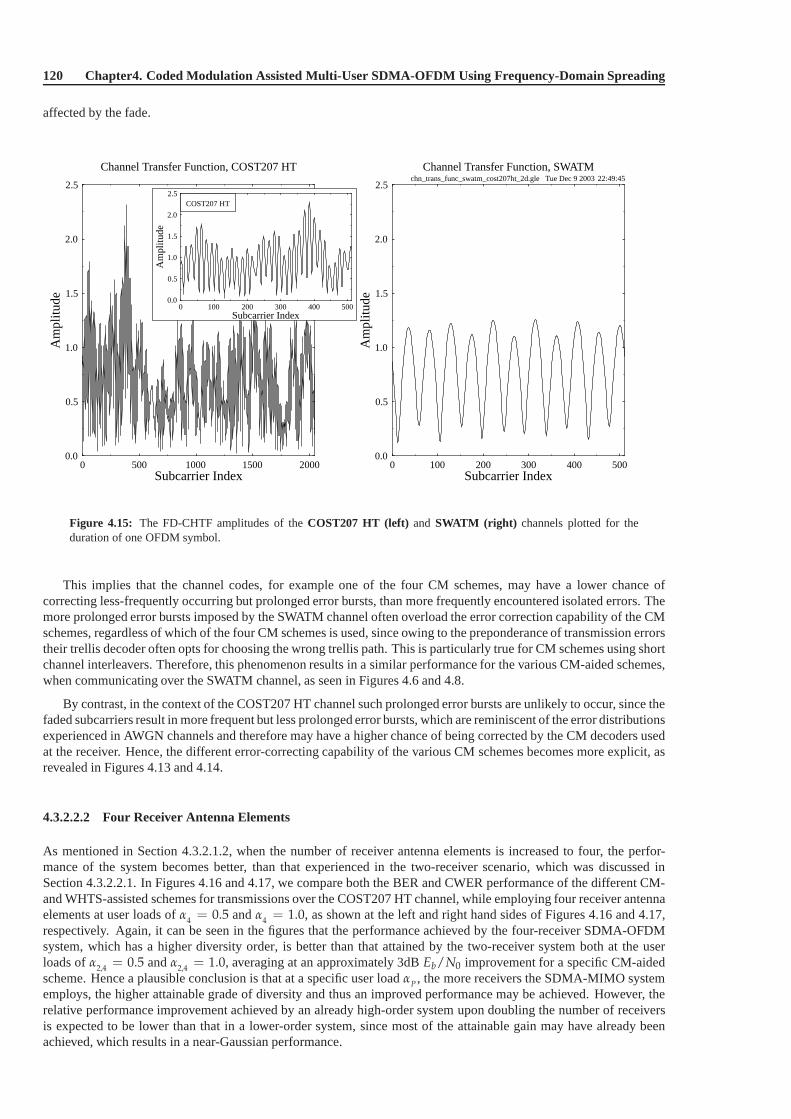
120 Chapter4. Coded Modulation Assisted Multi-User SDMA-OFDM Using Frequency-Domain Spreading
affected by the fade.
chn_trans_func_swatm_cost207ht_2d.gle Tue Dec 9 2003 22:49:45
0 500 1000 1500 2000Subcarrier Index
0.0
0.5
1.0
1.5
2.0
2.5
Am
plitu
de
Channel Transfer Function, COST207 HT
0 100 200 300 400 500Subcarrier Index
0.0
0.5
1.0
1.5
2.0
2.5
Am
plitu
de
COST207 HT
0 100 200 300 400 500Subcarrier Index
0.0
0.5
1.0
1.5
2.0
2.5
Am
plitu
de
Channel Transfer Function, SWATM
Figure 4.15: The FD-CHTF amplitudes of theCOST207 HT (left) and SWATM (right) channels plotted for theduration of one OFDM symbol.
This implies that the channel codes, for example one of the four CM schemes, may have a lower chance ofcorrecting less-frequently occurring but prolonged errorbursts, than more frequently encountered isolated errors.Themore prolonged error bursts imposed by the SWATM channel often overload the error correction capability of the CMschemes, regardless of which of the four CM schemes is used, since owing to the preponderance of transmission errorstheir trellis decoder often opts for choosing the wrong trellis path. This is particularly true for CM schemes using shortchannel interleavers. Therefore, this phenomenon resultsin a similar performance for the various CM-aided schemes,when communicating over the SWATM channel, as seen in Figures 4.6 and 4.8.
By contrast, in the context of the COST207 HT channel such prolonged error bursts are unlikely to occur, since thefaded subcarriers result in more frequent but less prolonged error bursts, which are reminiscent of the error distributionsexperienced in AWGN channels and therefore may have a higherchance of being corrected by the CM decoders usedat the receiver. Hence, the different error-correcting capability of the various CM schemes becomes more explicit, asrevealed in Figures 4.13 and 4.14.
4.3.2.2.2 Four Receiver Antenna Elements
As mentioned in Section 4.3.2.1.2, when the number of receiver antenna elements is increased to four, the perfor-mance of the system becomes better, than that experienced inthe two-receiver scenario, which was discussed inSection 4.3.2.2.1. In Figures 4.16 and 4.17, we compare boththe BER and CWER performance of the different CM-and WHTS-assisted schemes for transmissions over the COST207 HT channel, while employing four receiver antennaelements at user loads ofα
4= 0.5 andα
4= 1.0, as shown at the left and right hand sides of Figures 4.16 and 4.17,
respectively. Again, it can be seen in the figures that the performance achieved by the four-receiver SDMA-OFDMsystem, which has a higher diversity order, is better than that attained by the two-receiver system both at the userloads ofα
2,4= 0.5 andα
2,4= 1.0, averaging at an approximately 3dBEb/N0 improvement for a specific CM-aided
scheme. Hence a plausible conclusion is that at a specific user loadαP , the more receivers the SDMA-MIMO systememploys, the higher attainable grade of diversity and thus an improved performance may be achieved. However, therelative performance improvement achieved by an already high-order system upon doubling the number of receiversis expected to be lower than that in a lower-order system, since most of the attainable gain may have already beenachieved, which results in a near-Gaussian performance.

4.3.2. CM- and WHTS-assisted MMSE-SDMA-OFDM 121
d_u24r4_mmse_cm_4qam_cost207ht.gle Sun Jan 30 2005 11:18:32
0 1 2 3 4 5 6 7 8 9 10Eb/N0 (dB)
10-5
10-4
10-3
10-2
10-1
100
BE
R
CM-MMSE-SDMA-OFDM, L2/P4, 4QAM, COST207 HT
BICM-IDBICMTTCMTCM(No FEC)(AWGN)
0.0 0.4 0.8 1.2 1.6 2.0Eb/N0 (dB)
10-5
2
5
10-4
2
5
10-3
BE
R
0 1 2 3 4 5 6 7 8 9 10Eb/N0 (dB)
10-5
10-4
10-3
10-2
10-1
100
BE
R
CM-MMSE-SDMA-OFDM, L4/P4, 4QAM, COST207 HT
BICM-IDBICMTTCMTCM(No FEC)(AWGN)
d_u24r4_mmse_wht32_cm_4qam_cost207ht.gle Sun Jan 30 2005 11:19:56
0 1 2 3 4 5 6 7 8 9 10Eb/N0 (dB)
10-5
10-4
10-3
10-2
10-1
100
BE
R
CM-WHTS-MMSE-SDMA-OFDM,L2/P4,4QAM,COST207 HT
BICM-ID, WHTSBICM, WHTSTTCM, WHTSTCM, WHTS(No FEC)(AWGN)
0.0 0.4 0.8 1.2 1.6 2.0Eb/N0 (dB)
10-5
2
5
10-4
2
5
10-3
BE
R
0 1 2 3 4 5 6 7 8 9 10Eb/N0 (dB)
10-5
10-4
10-3
10-2
10-1
100
BE
R
CM-WHTS-MMSE-SDMA-OFDM,L4/P4,4QAM,COST207 HT
BICM-ID, WHTSBICM, WHTSTTCM, WHTSTCM, WHTS(No FEC)(AWGN)
Figure 4.16: BER versusEb/N0 performance of theCM-assisted MMSE-SDMA-OFDM (top) and CM- andWHTS-assisted MMSE-SDMA-OFDM (bottom) systems employing a 4QAM scheme for transmission over theCOST207 HT channel, whereL=2 (left) or L=4 (right) users are supported with the aid ofP=4 receiver antennaelements. The CM parameters are given in Table 4.3. The CM codeword length is2048symbols and the WHT blocksize used is32.

122 Chapter4. Coded Modulation Assisted Multi-User SDMA-OFDM Using Frequency-Domain Spreading
d_u24r4_mmse_cm_4qam_cost207ht_cwer.gle Sun Jan 30 2005 11:21:30
0 1 2 3 4 5 6 7 8 9 10Eb/N0 (dB)
10-3
2
5
10-2
2
5
10-1
2
5
100
CW
ER
CM-MMSE-SDMA-OFDM, L2/P4, 4QAM, COST207 HT
BICM-IDBICMTTCMTCM
0 1 2 3 4 5 6 7 8 9 10Eb/N0 (dB)
10-3
2
5
10-2
2
5
10-1
2
5
100
CW
ER
CM-MMSE-SDMA-OFDM, L4/P4, 4QAM, COST207 HT
BICM-IDBICMTTCMTCM
d_u24r4_mmse_wht32_cm_4qam_cost207ht_cwer.gle Sun Jan 30 2005 11:22:20
0 1 2 3 4 5 6 7 8 9 10Eb/N0 (dB)
10-3
2
5
10-2
2
5
10-1
2
5
100
CW
ER
CM-WHTS-MMSE-SDMA-OFDM,L2/P4,4QAM,COST207 HT
BICM-ID, WHTSBICM, WHTSTTCM, WHTSTCM, WHTS
0 1 2 3 4 5 6 7 8 9 10Eb/N0 (dB)
10-3
2
5
10-2
2
5
10-1
2
5
100
CW
ER
CM-WHTS-MMSE-SDMA-OFDM,L4/P4,4QAM,COST207 HT
BICM-ID, WHTSBICM, WHTSTTCM, WHTSTCM, WHTS
Figure 4.17: CWER versusEb/N0 performance of theCM-assisted MMSE-SDMA-OFDM (top) and CM- andWHTS-assisted MMSE-SDMA-OFDM (bottom) systems employing a 4QAM scheme for transmission over theCOST207 HT channel, whereL=2 (left) or L=4 (right) users are supported with the aid ofP=4 receiver antennaelements. The CM parameters are given in Table 4.3. The CM codeword length is2048symbols and the WHT blocksize used is32.

4.3.2. CM- and WHTS-assisted MMSE-SDMA-OFDM 123
4.3.2.2.3 Performance Comparisons
CM α2,4
= 0.5 α2,4
= 1.0
Schemes Spreading U1R2 U2R4 U2R2 U4R4
No WHTS 20.85 12.99 41.97 38.85
(No FEC) WHTS 14.53 9.53 23.30 20.78
Eb/N0 Gain 6.32 3.46 18.67 18.07
No WHTS 5.53 1.73 10.28 6.91
TCM WHTS 4.62 1.45 8.88 6.11
Eb/N0 Gain 0.91 0.28 1.40 0.80
No WHTS 2.60 0.41 5.87 2.41
TTCM WHTS 2.47 0.38 5.61 2.35
Eb/N0 Gain 0.13 0.03 0.26 0.06
No WHTS 4.47 1.08 8.72 5.25
BICM WHTS 4.06 1.03 7.97 4.73
Eb/N0 Gain 0.41 0.05 0.75 0.52
No WHTS 4.48 0.88 8.89 5.35
BICM-ID WHTS 3.92 0.79 8.15 4.96
Eb/N0 Gain 0.56 0.09 0.74 0.39
Table 4.4: The Eb/N0 values required and the spreading-induced gains achieved at the BER of10−5 of the various
CM- and WHTS-assisted MMSE-SDMA-OFDM schemes for communicating over the COST207 HT channel. The CM
parameters are given in Table 4.3. The CM codeword length is 2048 symbols and the WHT block size used is 32. All
data are in dB.
Table 4.4 summarizes theEb/N0 values required by the various CM- and WHTS-assisted MMSE-SDMA-OFDMschemes for achieving a BER of10−5. The corresponding spreading-inducedEb/N0 gains achieved by the WHTS-assisted schemes are also provided, which are defined as theEb/N0 difference, expressed in terms of dBs, at a BERof 10−5 between the WHTS-assisted and the unspreading system having the same effective throughput.
Several useful points can be concluded from Table 4.4. Firstly, when we have a specific user load, the spreading-inducedEb/N0 gain achieved by a system having a lower diversity order is higher, regardless whether CM is employedor not. For example, when we have a user load ofα
2,4= 0.5, the spreading-inducedEb/N0 gains achieved in the
No-FEC-, TCM-, TTCM-, BICM- and BICM-ID-assisted two-receiver systems are 6.32, 0.91, 0.13, 0.41 and 0.56dB,respectively. By contrast, lower spreading-inducedEb/N0 gains of 3.46, 0.28, 0.03, 0.05 and 0.09dB are achieved inthe corresponding four-receiver systems, respectively. In other words, in relatively lower diversity-order scenarios, thesubcarrier-based WHTS technique may be expected to attain ahigher system performance improvement.
Furthermore, if the number of users supported is fixed but thenumber of receiver antenna elements is varied,similar conclusions may be drawn. When there are two simultaneous users, for example, the spreading-inducedEb/N0 gains achieved in the two-receiver scenario, are higher than those achieved in the four-receiver scenario, asobserved in Table 4.4. A plausible explanation for this factmay be as follows. In the SDMA-MIMO system, whena higher number of receiver antenna elements is employed, a potentially higher space diversity can be achieved. Inthis scenario, the benefits of spreading may be less substantial, especially in the CM-aided system, since most of theattainable gain has already been achieved by using the channel codes.
Secondly, when the BS employs a given number of receiver antenna elements, the spreading-inducedEb/N0
gains achieved in the context of the fully-loaded systems are higher than in the half-loaded systems, regardless ofthe employment of channel codes. For instance, if we have tworeceivers installed in the BS, the various schemeshaving a user load ofα2 = 1.0 attain a higher spreading-inducedEb/N0 gain, than their half-loaded counterparts, asseen in Table 4.4. This suggests that more benefits may arise from WHTS, especially in the fully-loaded scenarios,where the MUD suffers from a relatively low efficiency in differentiating the different users’ signals. Furthermore, if

124 Chapter4. Coded Modulation Assisted Multi-User SDMA-OFDM Using Frequency-Domain Spreading
a longer WHT block size is used, theEb/N0 gain of WHTS may even be higher, since the detrimental burstyerroreffects degrading the system’s average BER performance will be spread over a higher block length, hence increasingthe chances of correcting a higher number of errors, as it will be presented in Section 4.3.2.3.
uxr4_mmse_wht32_ttcm_4qam_cost207ht.gle Sun Jan 30 2005 11:24:01
0 1 2 3 4 5 6 7 8 9 10Eb/N0 (dB)
10-5
10-4
10-3
10-2
10-1
100
BE
R
TTCM-WHTS-MMSE-SDMA-OFDM, Lx/P4, 4QAM, COST207 HT
L4/P4, TTCM, WHTSL3/P4, TTCM, WHTSL2/P4, TTCM, WHTSL1/P4, TTCM, WHTSL1/P1 (AWGN)
0.0 0.2 0.4 0.6 0.8 1.0Eb/N0 (dB)
10-5
2
5
10-4
2
5
10-3
BE
R
Figure 4.18: BER versusEb/N0 performance of theTTCM- and WHTS-assisted MMSE-SDMA-OFDM systememploying a 4QAM scheme for transmission over theCOST207 HT channel, whereL=1, 2, 3, 4users are supportedwith the aid ofP=4 receiver antenna elements. The TTCM parameters are given inTable 4.3. The TTCM codewordlength is2048symbols and the WHT block size used is32.
In order to characterize the system’s performance at different user loads, as an example, we portray the BERperformance of the TTCM- and WHTS-aided scheme at a range of different user loads in Figure 4.18. As expected,the system’s performance improves, when the user load is lower, since the MUD will have a better chance of separatingthe different users’ signals. It is also observed in Figure 4.18 that the relevantEb/N0 gain achieved by a lower-loadscheme over a higher-load arrangement reduces, when the user load decreases. This again shows that most of theachievableEb/N0 gain has already been attained at a medium user load.
Figure 4.19 shows theEb/N0 crossing points of the various CM-WHTS-MMSE-SDMA-OFDM schemes at theBER of 10−5. It is shown explicitly that the performance gap between thedifferent CM-aided schemes increases asthe user load increases. Furthermore, from Figure 4.19 we see that the TTCM-aided scheme performs best in highuser-load scenarios, namely forα
4≥ 0.5. In other words, the other three CM schemes, namely the TCM, BICM and
BICM-ID arrangements will suffer a higher performance degradation than TTCM, when the MUD’s user-separationcapability erodes owing to the increased MUI.
In Figure 4.20 we compare the total gain achieved by the four different CM-aided schemes, which includes boththe coding gain and the spreading-inducedEb/N0 gain. As the figure indicates, the TTCM-aided scheme achieved afurtherEb/N0 gain of 3.76dB, 2.38dB and 2.61dB over the TCM, BICM and BICM-ID aided schemes in the fully-loaded scenario, respectively. At a relatively low user load, namely forα
4≤ 0.5, the various schemes provide a
similar performance, because most of the attainable gain inthe four-receiver SDMA-OFDM system has already beenachieved, as discussed earlier in this section.
4.3.2.3 Effects of the WHT Block Size
In Sections 4.3.2.1 and 4.3.2.2 we have investigated the CM-and WHTS-assisted MMSE-SDMA-OFDM system fortransmission over the SWATM and COST207 HT channel, respectively. In this section, we will study how the variationof the WHT block size affects the system’s performance, whencommunicating over the above two channel models.
As mentioned in Section 4.3.2.2.3, when a larger WHT block size is used for the SDMA-OFDM system, thesystem’s performance may potentially be improved, since the signals carried by the subcarriers that are badly-affected
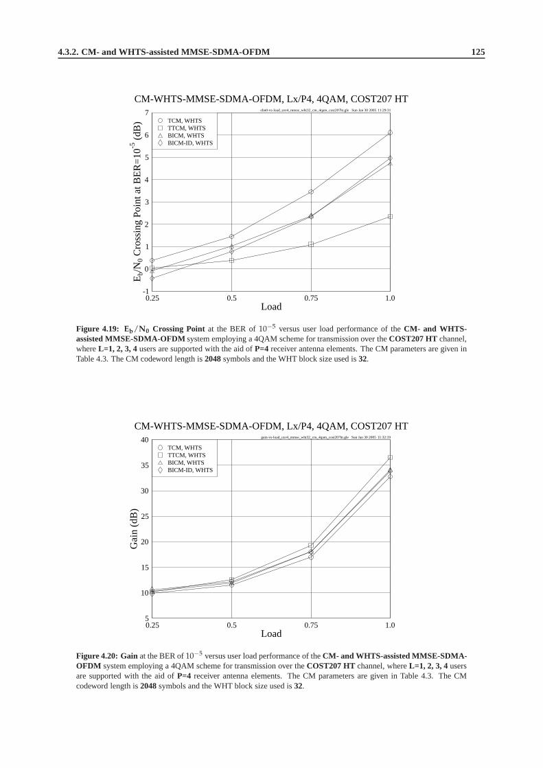
4.3.2. CM- and WHTS-assisted MMSE-SDMA-OFDM 125
ebn0-vs-load_uxr4_mmse_wht32_cm_4qam_cost207ht.gle Sun Jan 30 2005 11:29:31
0.25 0.5 0.75 1.0Load
-1
0
1
2
3
4
5
6
7
Eb/
N0
Cro
ssin
gP
oint
atB
ER
=10-5
(dB
)
CM-WHTS-MMSE-SDMA-OFDM, Lx/P4, 4QAM, COST207 HT
BICM-ID, WHTSBICM, WHTSTTCM, WHTSTCM, WHTS
Figure 4.19: Eb/N0 Crossing Point at the BER of10−5 versus user load performance of theCM- and WHTS-assisted MMSE-SDMA-OFDMsystem employing a 4QAM scheme for transmission over theCOST207 HTchannel,whereL=1, 2, 3, 4users are supported with the aid ofP=4 receiver antenna elements. The CM parameters are given inTable 4.3. The CM codeword length is2048symbols and the WHT block size used is32.
gain-vs-load_uxr4_mmse_wht32_cm_4qam_cost207ht.gle Sun Jan 30 2005 11:32:19
0.25 0.5 0.75 1.0Load
5
10
15
20
25
30
35
40
Gai
n(d
B)
CM-WHTS-MMSE-SDMA-OFDM, Lx/P4, 4QAM, COST207 HT
BICM-ID, WHTSBICM, WHTSTTCM, WHTSTCM, WHTS
Figure 4.20: Gainat the BER of10−5 versus user load performance of theCM- and WHTS-assisted MMSE-SDMA-OFDM system employing a 4QAM scheme for transmission over theCOST207 HT channel, whereL=1, 2, 3, 4usersare supported with the aid ofP=4 receiver antenna elements. The CM parameters are given in Table 4.3. The CMcodeword length is2048symbols and the WHT block size used is32.

126 Chapter4. Coded Modulation Assisted Multi-User SDMA-OFDM Using Frequency-Domain Spreading
d_dfwht_u2r2_mmse_whtx_ttcm_4qam_swatm.gle Sun Jan 30 2005 11:41:28
0 5 10 15 20 25 30Eb/N0 (dB)
10-5
10-4
10-3
10-2
10-1
100
BE
R
WHTS-MMSE-SDMA-OFDM, L2/P2, 4QAM, SWATM
(No FEC), Blk=64(No FEC), Blk=32(No FEC), Blk=16(No FEC), Blk=8(No FEC)(AWGN)
0 2 4 6 8 10 12 14 16 18 20Eb/N0 (dB)
10-5
10-4
10-3
10-2
10-1
100
BE
R
TTCM-WHTS-MMSE-SDMA-OFDM, L2/P2, 4QAM, SWATM
TTCM, Blk=64TTCM, Blk=32TTCM, Blk=16TTCM, Blk=8TTCM(No FEC)(AWGN)
Figure 4.21: BERversusEb/N0 performance of theWHTS-assisted MMSE-SDMA-OFDM (left) andTTCM- andWHTS-assisted MMSE-SDMA-OFDM (right) systems usingdifferent WHT block size and employing a 4QAMscheme for transmission over theSWATM channel, whereL=2 users are supported with the aid ofP=2receiver antennaelements. The TTCM parameters are given in Table 4.1 and the TTCM codeword length is1024symbols.
d_dfwht_u2r2_mmse_whtx_ttcm_4qam_cost207ht.gle Sun Jan 30 2005 11:43:06
0 5 10 15 20 25 30Eb/N0 (dB)
10-5
10-4
10-3
10-2
10-1
100
BE
R
WHTS-MMSE-SDMA-OFDM,L2/P2,4QAM,COST207 HT
(No FEC), Blk=64(No FEC), Blk=32(No FEC), Blk=16(No FEC), Blk=8(No FEC)(AWGN)
0 1 2 3 4 5 6 7 8 9 10Eb/N0 (dB)
10-5
10-4
10-3
10-2
10-1
100
BE
R
TTCM-WHTS-MMSE-SDMA-OFDM,L2/P2,4QAM,COST207 HT
TTCM, Blk=64TTCM, Blk=32TTCM, Blk=16TTCM, Blk=8TTCM(No FEC)(AWGN)
Figure 4.22: BERversusEb/N0 performance of theWHTS-assisted MMSE-SDMA-OFDM (left) andTTCM- andWHTS-assisted MMSE-SDMA-OFDM (right) systems usingdifferent WHT block size and employing a 4QAMscheme for transmission over theCOST207 HT channel, whereL=2 users are supported with the aid ofP=2 receiverantenna elements. The TTCM parameters are given in Table 4.3and the TTCM codeword length is2048symbols.

4.3.2. CM- and WHTS-assisted MMSE-SDMA-OFDM 127
by deep channel fades could be spread over a larger set of subcarriers, which may mitigate the detrimental channeleffects and thus assists the receiver in achieving a better performance. In order to show the effects imposed bydifferent-length WHTS schemes, we provide simulation results generated in the context of different WHT block sizesin both the No-CM and CM-aided scenarios, as shown in the leftand right hand sides of Figure 4.21, respectively. Asexpected, the system’s performance was improved upon increasing the WHT block size, regardless whether CM wasemployed or not. In the context of the COST207 HT channel of Figure 4.12, similarly, a performance improvement isobserved, when an increased WHT block size is employed as portrayed in Figure 4.22.
Furthermore, we may notice that the spreading-inducedEb/N0 gains achieved by the No-CM schemes, when us-ing a larger WHT block size, are significantly higher than those attained by the TTCM-aided schemes, as observed inFigures 4.21 and 4.22. This suggests that in the SDMA-OFDM system employing no CM, the performance improve-ment potential owing to the employment of a larger WHT block size is higher than that in the CM-aided system, wheremost of the achievable diversity gain has been attained by the time-diversity of the CM schemes. However, as sug-gested by Table 4.2, the other three CM-aided schemes, for example the TCM-aided arrangement, may be capable ofachieving a higher spreading-induced gain than the TTCM-aided scheme with the aid of WHTS. Therefore, owing totheir lower time-diversity and relatively more modest unspread performance, a potentially higher spreading-inducedEb/N0 gain may be achieved by combining WHTS with the TCM, BICM and BICM-ID assisted schemes than inconjunction with the TTCM-aided arrangement, when a largerWHT block size is used. Having studied the effects ofdifferent WHT block sizes, let us now consider the impact of varying the Doppler frequency.
4.3.2.4 Effects of the Doppler Frequency
ebn0-vs-doppler_u2r2_mmse_wht32_ttcm_4qam_cost207ht.gle Sun Jan 30 2005 11:58:20
0 20 40 60 80 100 120 140 160 180 200Maximum Doppler Frequency (Hz)
0
10
20
30
40
Eb/
N0
Cro
ssin
gP
oint
atB
ER
=10-5
(dB
)
TTCM-WHTS-MMSE-SDMA-OFDM, L2/P2, 4QAM, COST207 HT
TTCM, WHTS(No FEC), WHTS
Figure 4.23: Eb/N0 Crossing Point at the BER of10−5 versus maximum Doppler frequency performance of theTTCM- and WHTS-assisted MMSE-SDMA-OFDM system employing a 4QAM scheme for transmission over theCOST207 HT channel, whereL=2 users are supported with the aid ofP=2 receiver antenna elements. The TTCMparameters are given in Table 4.3. The TTCM codeword length is 2048symbols and the WHT block size used is32.
In our further investigations we have generated the BER versusEb/N0 curves of the TTCM- and WHTS-assistedMMSE-SDMA-OFDM system communicating over the COST207 HT channel, when the maximum Doppler fre-quency was fixed to a range of different values. For simplicity, here we have assumed perfect channel estimation.As before, the CIR of the 12-path COST207 HT channel of Figure4.12 was used. For the sake of presenting theseresults in a compact form, theEb/N0 values required for maintaining a BER of10−5 were extracted. In Figure 4.23,we show theEb/N0 crossing point at BER=10−5 versus the maximum Doppler frequency for the WHTS-assistedMMSE-SDMA-OFDM system both with and without the aid of TTCM,where two receivers were used for supportingtwo users. We conclude from the near-horizontal curves shown in Figure 4.23 that the maximum Doppler frequencydoes not significantly affect the performance of the WHTS-assisted MMSE-SDMA-OFDM system, regardless of theemployment of TTCM. This may be a desirable benefit of the error-randomizing effect of WHTS, resulting in a robust-
128 Chapter4. Coded Modulation Assisted Multi-User SDMA-OFDM Using Frequency-Domain Spreading
ness against the variation of the mobile speed. Moreover, asexpected, the performance of the TTCM-aided schemewas consistently better, than that of the scheme using no channel coding, as evidenced by Figure 4.23.
It is worth noting that when the channel’s Doppler frequencyis high, the effects of Inter-Carrier Interference (ICI)may become significant1, as argued on page 81 of [5]. In this case for example the ICI-cancellation techniques ofChapter 4 in [5] may be invoked for combating the ICI effects.
4.4 Chapter Summary
The system model of our multi-user uplink SDMA-based OFDM system was presented in Section 4.2, where theSDMA-MIMO channel model was introduced in Section 4.2.1, followed by the detailed description of the CM-assistedmulti-user SDMA-OFDM system employing the frequency-domain subcarrier-based WHTS scheme of Section 4.2.2.The theoretical foundations of the Minimum Mean-Square Error based Multi-User Detector were provided in Sec-tion 4.2.2.1. Furthermore, a detailed discussion of the WHTS technique was presented in Section 4.2.2.2.
In Section 4.3 the performance of the various CM- and WHTS-assisted MMSE-SDMA-OFDM schemes wasstudied and compared. The uncoded MMSE-SDMA-OFDM system was first investigated in Section 4.3.1, where itwas found that WHTS was capable of improving the system’s performance, since the bursty subcarrier errors can bepseudo-randomly spread across the subcarriers of the entire WHT block. In the investigations outlined in Section 4.3.2our performance comparison among the different CM- and WHTS-assisted MMSE-SDMA-OFDM schemes was de-tailed. Specifically, the unspread CM-aided SDMA-OFDM system using two receiver antenna elements was studiedin Section 4.3.2.1.1, whose performance was compared to that of the WHTS-assisted system dispensing with the em-ployment of CM. Firstly, it was found that the performance achieved by all half-loaded schemes was better than thatattained by the fully-loaded arrangements. This is because, when the user load is lower, the MUD will achieve a higherefficiency in differentiating the different users’ transmitted signal, since the multi-user interference is lower. There-fore, the system becomes more efficient in terms of suppressing the detrimental fading channel effects. Secondly, itwas also noticed that the achievable performance improvement attained by CM was typically higher than that achievedby WHTS, as evidenced by comparing Figure 4.5 to Figure 4.7.
Furthermore, we combined the MMSE-SDMA-OFDM system with both CM and WHTS in Section 4.3.2.1.1.The corresponding simulation results portrayed in Figure 4.8 showed that the TTCM-aided scheme achieved thebest CWER performance among all the CM- and WHTS-assisted schemes considered. Moreover, the comparison ofFigure 4.6 and Figure 4.8 suggested that in the CM-aided MMSE-SDMA-OFDM system the employment of WHTShaving a block size of 32 subcarriers only insignificantly improved the system’s BER and CWER performance, sincemost of the achievable diversity gain may have already been achieved by the time-diversity of the CM schemes. Itwas also found that when a higher CM codeword length was used,the system’s performance was further improved, asobserved in Figure 4.9, since a longer CM codeword is capableof more efficiently dispersing and averaging the burstyerror effects.
In Section 4.3.2.1.2, the system’s performance evaluated in the four-receiver CM scenarios was compared, whencommunicating over the SWATM channel of Figure 3.32. Comparing Figure 4.8 to Figure 4.10, we found that at thesame user load level, for example atα4 = α2 = 0.5 or α4 = α2 = 1.0, the Eb/N0 performance achieved by thefour-receiver system was better than that of the two-receiver system, provided that the same CM-assisted scheme wasused. The reason for this phenomenon is that when the SDMA-MIMO system’s space-diversity order is increasedby employing a higher number of receiver antenna elements, it becomes capable of providing a higher diversity gain,which may be expected to improve the system’s performance for each user.
The performance of the various CM- and WHTS-assisted MMSE-SDMA-OFDM systems was evaluated in thecontext of the COST207 HT channel of Figure 4.12 in Section 4.3.2.2, which included the two- and four-receiverscenarios in Section 4.3.2.2.1 and Section 4.3.2.2.2, respectively. It was found that without the assistance of WHTSthe TTCM-aided scheme constituted the best design option interms of both the BER and CWER in comparison to theother three CM-aided schemes. When WHTS was incorporated into the CM-MMSE-SDMA-OFDM system, a furtherEb/N0 gain was achieved by all the schemes, which was different from the scenario of Section 4.3.2.1 recorded fortransmission over the SWATM channel, where the additionalEb/N0 gain achieved by WHTS in the context of thevarious CM- and WHTS-assisted schemes was rather modest. This may suggest that in highly dispersive environments,such as that characterized by the 12-path COST207 HT channelof Figure 4.12, the channel-coded SDMA-OFDM
1Since the ICI is caused by the variation of the channel impulse response during the transmission of each OFDM symbol, we introduce theOFDM-symbol-normalized Doppler frequencyFd [5]. In the case of a maximum Doppler frequency of 200Hz, for example, the correspondingOFDM-symbol-normalized Doppler frequencyFd will become as high asFd = fd · NTs = f ′d · N = 0.023, whereN is the cyclically-extendedOFDM symbol’s total duration expressed asN = K + cp, while the associated values offd, f ′d, Ts, K andcp are given in Table 4.2.

4.4. Chapter Summary 129
system’s performance may be further improved by employing WHTS. This is because the detrimental fading-inducedbursty error effects degrading the system’s average BER performance owing to the deeply-faded subcarriers can bespread over the entire WHT block, and these dispersed and randomized channel errors may be more readily correctedby the CM decoder.
Furthermore, the four CM-aided schemes communicating overthe COST207 HT channel of Figure 4.12 attaina different performance, as shown in Figures 4.13 and 4.14. This conclusion is different from what was noted inFigures 4.6 and 4.8, where the performance of the various CM-aided schemes communicating over the SWATMchannel of Figure 3.32 was more similar. This is owing to the more frequent and more dramatic amplitude variationof the FD-CHTF in the COST207 HT channel, which exhibits a significantly longer maximum path delay than thatof the SWATM channel, as indicated by Figure 4.15. This characteristic resulted in more randomly dispersed ratherthan burstily corrupted subcarrier symbols, which can be more readily corrected by the channel codes. Hence, inthe context of the COST207 HT channel of Figure 4.12, the different error-correcting capability of the various CMschemes becomes more explicit, than that exhibited in the scenario of the SWATM channel of Figure 3.32.
In Table 4.4 of Section 4.3.2.2.3 we summarized theEb/N0 values required by the various CM- and WHTS-assisted MMSE-SDMA-OFDM schemes for achieving a BER of10−5, also showing the corresponding gains attainedby the WHTS-assisted schemes. We observed that on one hand, when we had a specific user load, the spreading-inducedEb/N0 gain achieved by a system having a lower diversity order was higher, regardless of the employmentof CM. In other words, the subcarrier-based WHTS technique may be expected to attain a higher system performanceimprovement in relatively lower diversity-order scenarios. Moreover, if we supported a fixed number of users butvaried the number of receiver antenna elements, similar conclusions may be drawn. A plausible explanation for thisfact may be that in the SDMA-MIMO system, a potentially higher space diversity gain may be achieved, when ahigher number of receiver antenna elements is employed, andthus the benefits of WHTS may be less substantial.This may be particularly true in the context of the CM-aided systems, since most of the attainable gain has alreadybeen achieved by using the channel codes. On the other hand, when a given number of receiver antenna elementswas used, the spreading-inducedEb/N0 gains achieved in the context of the fully-loaded systems were higher thanin the half-loaded systems, regardless of the employment ofchannel codes. This suggests that more benefits mayarise from WHTS, especially in the fully-loaded scenarios,where the MUD suffers from a relatively low efficiency indifferentiating the different users’ signals.
Additionally, we provided theEb/N0 crossing points and the corresponding total gain achieved by the variousCM-WHTS-MMSE-SDMA-OFDM schemes at the BER of10−5, in Figures 4.19 and 4.20 of Section 4.3.2.2.3, re-spectively. It was demonstrated that the performance gap between the different CM-aided schemes increased, as theuser load increased. Furthermore, it was observed in Figures 4.19 and 4.20 that the TCM, BICM and BICM-ID-aidedschemes suffered a higher performance degradation than theTTCM arrangement, when the MUD’s user-separationcapability eroded owing to the increased multi-user interference. At a relatively low user load the various schemesprovided a similar performance, because most of the attainable gain of the four-receiver SDMA-OFDM system hadalready been achieved, as discussed earlier in Section 4.3.2.2.3.
The effects of using different WHT block sizes was studied inSection 4.3.2.3, in both the SWATM and COST207HT channel scenarios, as seen in Figures 4.21 and 4.22, respectively. As expected, it was found that the system’sperformance was improved, while the WHT block size used was increased. This is because when a larger WHTblock size is used by the SDMA-OFDM system, the data symbols carried by the subcarriers that are badly-affectedby deep channel fades could be spread over a larger WHT length, which may mitigate the detrimental channel effectsand thus assists the receiver in terms of achieving a better error correction capability. Furthermore, it was suggestedby the simulation results of Section 4.3.2.3 that in the SDMA-OFDM system operating without the aid of CM, theperformance improvement potential owing to the employmentof a larger WHT block size was higher than that in theCM-aided system, where most of the achievable diversity gain has been attained by using CM.
Finally, we studied the effects of the Doppler frequency in Section 4.3.2.4. It was concluded that the maximumDoppler frequency does not significantly affect the performance of the WHTS-assisted MMSE-SDMA-OFDM system,regardless of the employment of CM, as for example portrayedin Figure 4.23.
From the investigations conducted, we conclude that the various CM schemes, namely TCM, TTCM, BICM andBICM-ID are capable of substantially improving the achievable performance of SDMA-OFDM systems. The em-ployment of WHTS has the potential of further enhancing the system’s performance in highly dispersive propagationenvironments. As a result, the TTCM- and WHTS-assisted scheme was found to have the best CWER performance inall the scenarios investigated. Furthermore, it was also the best design option in terms of the achievableEb/N0 gainexpressed in dB, when communicating in highly dispersive environments, for example over the COST207 HT channelof Figure 4.12, while carrying a high user load ofαP ≥ 0.5.
In the next chapter, our research is targeted at contriving amore sophisticated MUD, namely the Genetic Algorithm

130 Chapter4. Coded Modulation Assisted Multi-User SDMA-OFDM Using Frequency-Domain Spreading
(GA) assisted MUD, in order to further improve the SDMA-OFDMsystem’s achievable performance.

Chapter5Hybrid Multi-User Detection forSDMA-OFDM Systems
5.1 Introduction
In the previous chapter, the MMSE MUD has been investigated in the context of various CM schemes assisted SDMA-OFDM systems. Furthermore, the WHT-based frequency-domain spreading technique has been incorporated into theCM-assisted MMSE-SDMA-OFDM system for the sake of attaining performance enhancements. However, the SDMAsystem’s performance is somewhat limited due to the employment of the low-complexity MMSE MUD, which isdevised based on the sub-optimal linear MMSE algorithm. On the other hand, the high-complexity optimum MaximumLikelihood (ML) MUD is capable of achieving the best performance owing to invoking an exhaustive search. However,the computational complexity of the ML MUD typically increases exponentially with the number of simultaneoususers supported by the SDMA-OFDM system, which may render its implementation prohibitive. In the literature,a range of sub-optimal nonlinear MUDs have been proposed, such as for example the MUDs based on SuccessiveInterference Cancellation (SIC) [5, 194, 198, 442–444] or Parallel Interference Cancellation (PIC) [5, 442, 444, 445]techniques. Instead of detecting and demodulating the users’ signals in a sequential manner, as the MMSE MUDdoes, the PIC and SIC MUDs invoke an iterative processing technique that combines detection and demodulation.More specifically, the output signal generated during the previous detection iteration is demodulated and fed back tothe input of the MUD for the next iterative detection step. Similar techniques invoking decision-feedback have beenapplied also in the context of classic channel equalization. However, since the philosophy of both the PIC and SICMUDs is based on the principle of removing the effects of the interfering users during each detection stage, they areprone to error propagation occurring during the consecutive detection stages due to the erroneously detected signalsof the previous stages [5]. In order to mitigate the effects of error propagation, an attractive design alternative is tosimultaneouslydetect all the users’ signals, rather than invoking iterative interference cancellation schemes. Recently,another branch of multi-user detection schemes referred toas Sphere Decoder (SD) [448–454] has also been proposedfor multi-user systems, which is capable of achieving ML performance at a lower complexity.
As far as we are concerned, most of the above-mentioned techniques were proposed for the systems, where thenumber of users is less than or equal to the number of receivers, referred to here as the underloaded or fully-loadedscenarios, respectively. However, in practical applications it is possible that the number of usersL to be supportedexceeds that of the receiver antennasP, which is often referred to as anoverloadedscenario. In overloaded systems,the(P × L)-dimensional MIMO channel matrix representing the(P × L) number of channel links becomes singular,thus rendering the degree of freedom of the detector insufficient. This will catastrophically degrade the performance ofnumerous known detection approaches, such as for example the Vertical Bell Labs Layered Space-Time architecture(V-BLAST) [106, 109, 455] detector of [136], the MMSE algorithm of [5, 442] and the QR Decomposition combinedwith the M-algorithm (QRD-M) algorithm of [173].
Based on this motivation, in this chapter a sophisticated nonlinear MUD is devised, which exploits the powerof genetic algorithms. Genetic Algorithms (GAs) [456–460]have been applied to a number of problems, such asmachine learning and modeling adaptive processes. Moreover, GA-based multiuser detection has been proposed byJunttiet al.[461] and Wanget al.[462], where the analysis was based on the AWGN channel in theabsence of diversitytechniques. The proposal by Ergunet al. [463] utilized GAs as the first stage of a multistage multiuser detector, in

132 Chapter5. Hybrid Multi-User Detection for SDMA-OFDM Systems
order to provide good initial guesses for the subsequent stages. Its employment in Rayleigh fading channels wasconsidered by Yenet al. in [40, 464] and [40, 465] in diverse scenarios both with and without the aid of diversitytechniques, respectively.
However, most of the GA-aided transceiver research mentioned above was conducted in the context of Code Divi-sion Multiple Access (CDMA) systems [40, 466]. By contrast,in this chapter, we apply GAs in the context of multi-user OFDM schemes, rather than CDMA systems. More specifically, we combine GAs with the MMSE MUD for thesake of contriving a more powerful concatenated MMSE-GA MUD, which is capable of maintaining near-optimumperformance in the above-mentioned overloaded systems. Furthermore, TTCM is selected as the FEC scheme for theproposed MMSE-GA multi-user detected SDMA-OFDM system, since it generally provides the best performance inthe family of CM schemes in the context of MMSE-SDMA-OFDM systems, as demonstrated in Chapter 4. We willshow in this chapter that the proposed MMSE-GA assisted TTCM-SDMA-OFDM system is capable of achieving asimilar performance to that attained by its optimum ML MUD assisted counterpart at a significantly lower computa-tional complexity, especially at high user loads. Furthermore, the performance of the proposed GA-aided system canbe further improved, if an enhanced iterative GA MUD is employed. This improvement is achieved at the cost of anincreased complexity, which is however still substantially lower than that imposed by the ML MUD.
The structure of this chapter is as follows. The overview of the GA-assisted TTCM-aided MMSE-SDMA-OFDMsystem is given in Section 5.2.1, followed by the introduction of the basic principles of the concatenated MMSE-GAMUD of Section 5.2.2. Our simulation results are provided inSection 5.2.3, while the associated complexity issuesare discussed in Section 5.2.4. The enhanced GA MUD is introduced in Section 5.3, including the improved mutationscheme of Section 5.3.1 and the enhanced GA MUD framework of Section 5.3.2, while the associated simulationresults are provided in Sections 5.3.1.3 and 5.3.2.2, respectively, followed by the associated complexity analysis inSection 5.3.3. Our final conclusions are summarized in Section 5.4.
5.2 Genetical Algorithm Assisted Multi-User Detection
5.2.1 System Overview
…
…
…
User 1
Concatenated
MMSE-GA
MUD
IFFT
SDMA MIMO Channel
(1)s
(2)s
( )Ls
1x
2x
Px
(1)s
(2)s
( )ˆ Ls
User 1
User 2
FFT
FFT
Base Station (BS)
MS 1
Geographically-separated Mobile Stations (MSs)
…
…
…
…
…
User 2 IFFT
IFFT
MS 2
MS L User L
…
…
…
User L FFT
P-element Receiver Antenna Array
TTCM Encoder
TTCM Decoder
TTCM Decoder
TTCM Decoder
TTCM Encoder
TTCM Encoder
Figure 5.1: Schematic of the MMSE-GA-concatenated multi-user detected SDMA-OFDM uplink system.
In Figure 5.1, we present the schematic of the proposed concatenated MMSE-GA MUD aided SDMA-OFDMuplink system. At the transmitter end, as seen at the top of Figure 5.1, the information bit sequences of the geographi-cally separatedL simultaneous mobile users are forwarded to the TTCM [359] encoders, where they are encoded into

5.2.2. MMSE-GA-concatenated Multi-User Detector 133
symbols. The encoded signalss(l) (l = 1, · · · , L) of the L users are then forwarded to the OFDM-related InverseFast Fourier Transform (IFFT) based modulator, which converts the frequency-domain signals to the time-domainmodulated OFDM symbols. The OFDM symbols are then transmitted by the independent Mobile Stations (MSs) tothe Base Station (BS) over the SDMA MIMO channel, which has been presented in Section 4.2.1. Then each elementof the receiver antenna array shown at the bottom of Figure 5.1 receives the superposition of the transmitted signalsfaded and contaminated by the channel and performs Fast Fourier Transform (FFT) based OFDM demodulation. Thedemodulated outputsxp (p = 1, · · · , P) seen in Figure 5.1 are forwarded to the proposed concatenated MMSE-GA
MUD for separating the different users’ signals. The separated signalss(l) (l = 1, · · · , L), namely the estimatedversions of theL users’ transmitted signals, are then independently decoded by the TTCM decoders of Figure 5.1.
5.2.2 MMSE-GA-concatenated Multi-User Detector
5.2.2.1 Optimization Metric for the GA MUD
The optimum ML MUD [5] uses an exhaustive search for finding the most likely transmitted signals. More explicitly,for a ML-detection assisted SDMA-OFDM system supportingL simultaneous users, a total of2mL metric evaluationshas to be invoked, wherem denotes the number of bits per symbol (BPS), in order to detect theL-user symbol vectorsML that consists of the most likely transmitted symbols of theL users at a specific subcarrier, given by:
sML = arg
mins∈ML
||x − Hs||2
, (5.1)
where the(P × 1)-dimensional received signal vectorx and the(P × L)-dimensional Frequency-Domain CHannelTransfer Function (FD-CHTF) matrixH are defined by Equations (4.2) and (4.5), respectively. The setML in Equa-tion (5.1), which is constituted by2mL number of trial vectors, is formulated as:
ML =
s =[
s(1), s(2), · · · , s(L)]T
∣
∣
∣
∣
∣
s(1), s(2), · · · , s(L) ∈ Mc
, (5.2)
whereMc denotes the set containing the2m number of legitimate complex constellation points associated with thespecific modulation scheme employed. Explicitly, the number of metric evaluations required for detecting the optimumvector increases exponentially with the number of usersL.
Furthermore, the optimum ML-based decision metric of Equation (5.1) may also be used in the GA-based MUDfor the sake of detecting the estimated transmitted symbol vector sGA. In the context of the SDMA-OFDM systememployingP receiver antenna elements, the decision metric required for thepth receiver antenna, namely the antenna-specificobjective function (OF)[40] can be derived from Equation (5.1), yielding:
Ωp (s) = |xp − Hp s|2, (5.3)
wherexp is the received symbol at the input of thepth receiver at a specific OFDM subcarrier, whileHp is thepth rowof the channel transfer function matrixH. Therefore the decision rule for the optimum multiuser detector associatedwith the pth antenna is to choose the specificL-symbol vectors, which minimizes the metric given in Equation (5.3).Thus, the estimated transmitted symbol vector of theL users based on the knowledge of the received signal at thepth
receiver antenna and a specific subcarrier is given by:
sGAp = arg
mins
[
Ωp (s)]
. (5.4)
However, it transpires from above derivation that we will have P metrics in total for theP receiver antennas. Sincethe channel impulse responses of each of theP antennas are statistically independent, theL-symbol vector that isconsidered optimum at antenna 1 may not be considered optimum at antenna 2, etc. In other words, this implies that adecision conflict is encountered, which may be expressed as:
arg
mins
[Ωi (s)]
= sGAi6= sGAj
= arg
mins
[
Ωj (s)]
, (5.5)
where∀ i, j ∈ 1, · · · , P, i 6= j. This decision conflict therefore leads to a so-called multi-objective optimizationproblem, since the optimization of theP metrics may result in more than one possibleL-symbol solutions. A similardecision conflict resolution problem was studied in [467] inan attempt to reconcile the decision conflicts of multiple
134 Chapter5. Hybrid Multi-User Detection for SDMA-OFDM Systems
antennas resulting in a decision dilemma. In order to resolve this problem we may adopt a similar approach and mayamalgamate theP number of antenna-specificL-symbol metrics into a joint metric as follows:
Ω (s) =P
∑p=1
Ωp (s) . (5.6)
Hence, the decision rule of the GA MUD is to find the specific estimated transmittedL-symbol vectorsGA that mini-mizesΩ (s) in Equation (5.6) for every OFDM subcarrier considered.
5.2.2.2 Concatenated MMSE-GA Multi-User Detection
The BER performance of the MMSE MUD is somewhat limited, since it is the total mean-square estimation errorimposed by the different simultaneous users that is minimized, rather than directly optimizing the BER performance.Therefore, the MMSE-SDMA-OFDM system’s BER performance may be potentially further improved with the aidof a concatenated GA-aided MUD, which is capable of exploiting the output provided by the MMSE MUD of Sec-tion 4.2.2.1 in its initial population. For the sake of brevity, we will portray the philosophy of the proposed system inas simple terms as possible. However, the readers who are unfamiliar with GAs might like to consult Appendix A.1for a rudimentary introduction to GA-based optimization inthe context of multi-user SDMA-OFDM systems.
The GA invoked in the SDMA-OFDM system commences its search for the optimumL-symbol solution at theinitial generationwith the aid of the MMSE combiner. In other words, using GA parlance, the so-calledindivid-uals of the y = 1st generation having apopulationsize of X are created from the estimated length-L transmit-ted symbol vector provided by the MMSE combiner, where thexth (x = 1, · · · , X) individual is expressed as
s(y,x) = [ s(1)(y,x)
, s(2)(y,x)
, · · · , s(L)(y,x)
] , and we haves(l)(y,x)
∈ Mc (l = 1, · · · , L). Note that here a complex sym-
bol representation of the individuals is employed, which isderived from the classicbinary encodingtechnique [40],where a binary vector constituted by binary zeros and ones isused to represent an individual. Then the GA-basedoptimization selects some of theL-symbol candidates from a total ofX legitimate individuals in order to create aso-calledmating poolof T number ofL-symbolparentvectors [40]. TwoL-symbol parent vectors are then combinedusing specific GA operations for the sake of creating twoL-symboloffspring[40] and this ‘genetic evolution-like’ pro-cess of generating newL-symbol offspring continues overY number of consecutive generations, so that the optimumL-symbol solution may be found.
The selection of theL-symbol individuals for creating the mating pool containing T number ofL-symbol parentsis vital in determining the GA’s achievable quality of optimization [468]. In our research the individual-selectionstrategy based on the concept of the so-calledPareto Optimality[457] was employed. This strategy favours the so-callednon-dominatedindividuals and ignores the so-calleddominatedindividuals [40]. More specifically, theuth
L-symbol individual is considered to be dominated by thevth individual, if we have [469]:
∀i ∈ 1, · · · , P : Ωi
(
s(y,v)
)
≤ Ωi
(
s(y,u)
)
∧ ∃j ∈ 1, · · · , P : Ωj
(
s(y,v)
)
< Ωj
(
s(y,u)
)
. (5.7)
If an individual is not dominated in the sense of Equation (5.7) by any other individuals in the population, then itis considered to be non-dominated. All the non-dominated individuals are then selected and placed in the matingpool, which will have a size of2 < T ≤ X [40]. Two of the T number ofL-symbol individuals in the matingpool are then selected as parents based on their corresponding diversity-basedfitnessvalues calculated with the aid ofEquation (5.6) according to the so-calledfitness-proportionateselection scheme [40], which is described as follows.First the so-calledwindowing-mapping[462] technique is invoked in order to get the fitness valuef(y,x) associated
with thexth individual, which is given by:
f(y,x) = Ωy,T − Ω(
s(y,x)
)
+ c, (5.8)
where
Ωy,T = maxt∈1,··· ,T
Ω(
s(y,t)
)
(5.9)
is the maximumObjective Score (OS)1 achieved by evaluating theT number of individuals in the mating pool at theyth generation, andc is a small positive constant, which is used for the sake of ensuring the positiveness off(y,x).
1Note that the individual having the maximum OS out of the poolof the T candidates is considered as the worst solution in the context of thecurrent mating pool, since the GA searches for the optimum solution which minimizes Equation (5.6).

5.2.3. Simulation Results 135
Then the fitness-proportionate selection probabilitypx of thexth individual can be formulated as:
px =f(y,x)
∑Tt=1 f(y,t)
. (5.10)
When twoL-symbol parents are selected, the so-calleduniform cross-over, mutationandelitismoperations [40]are invoked for offering a chance of evolving the parents’ one or more element symbols to other symbols of the setMc, resulting in two offspring. The above operation is repeated, until a new population consisting ofX offspring iscreated. Furthermore, the so-calledincest prevention[40] technique was invoked during the selection process, whichonly allows different individuals to be selected for the cross-over operation. Finally, the GA terminates afterY numberof generations and thus theL-symbol individual having the highest diversity-based fitness value will be considered asthe detectedL-user transmitted symbol vector corresponding to the specific OFDM subcarrier considered.
From the above arguments, we note that in the GA MUD the different users’ signals are jointly detected. Thismechanism is different from that of the SIC or PIC MUDs, whereeach user’s estimated transmitted signal is inferredby removing the interference imposed by the others. Therefore, there is no error propagation between the differentusers’ signal detections in the GA MUD.
5.2.3 Simulation Results
In this section, we characterize the performance of the proposed TTCM-assisted SDMA-OFDM system using theconcatenated MMSE-GA MUD. The channel is assumed to be ‘OFDM-symbol-invariant’, implying that the taps of theimpulse response are assumed to be constant for the durationof one OFDM symbol, but they are faded at the beginningof each OFDM symbol [5]. The simulation results were obtained using a 4QAM scheme communicating over theSWATM CIR of Figure 3.32, assuming that the channels’ transfer functions are perfectly known. Each of the pathsexperiences independent Rayleigh fading having the same normalized Doppler frequencies off ′d = 1.235× 10⁻⁵. TheOFDM modem employedK = 512 subcarriers and a cyclic prefix of 64 samples, which is longerthan the maximumchannel delay spread. For the iterative TTCM scheme [359] employed, the code memoryν is fixed to 3, while thenumber of iterations is set to 4. Hence the total number of trellis states is23 · 4 · 2 = 64, since there are two 8-statedecoders which are invoked in four iterations. The generator polynomial expressed in octal format for the TTCMscheme considered is[13 6], while the codeword length and channel interleaver depth are fixed to1024 symbols.The various techniques and parameters used in our simulations discussed in this section are summarized in Table 5.1.
u6r6_mmse-ga-fp-po_ttcm_4qam_swatm.gle Sat Jun 12 2004 03:05:10
0 1 2 3 4 5 6 7 8 9 10Eb/N0 (dB)
10-5
10-4
10-3
10-2
10-1
100
BE
R
TTCM-MMSE-GA-SDMA-OFDM, L6/P6, 4QAM, SWATM
TTCM, ML (4096)TTCM, MMSE-GA, X80/Y5 (400)TTCM, MMSE-GA, X40/Y10 (400)TTCM, MMSE-GA, X20/Y10 (200)TTCM, MMSE-GA, X20/Y5 (100)TTCM, MMSE-GA, X10/Y10 (100)TTCM, MMSE(L1P6, AWGN)(L1P1, AWGN)
Figure 5.2: BER versusEb/N0 performance of theTTCM-assisted MMSE-GA-SDMA-OFDM system employing a4QAM scheme for transmission over the SWATM channel, whereL=6 users are supported with the aid ofP=6 receiverantenna elements. The basic simulation parameters are given in Table 5.1.

136 Chapter5. Hybrid Multi-User Detection for SDMA-OFDM Systems
Modem 4QAM
Code rate 0.5
Code memoryν 3
TTCM Octal generator polynomial [13 6]
Codeword length 1024 symbols
Channel interleaver depth 1024 symbols
Number of turbo iterations 4
Population initialization method MMSE
Mating pool creation strategy Pareto-Optimality
Selection method Fitness-Proportionate
Cross-over Uniform cross-over
GA Mutation M-ary mutation
Mutation probabilitypm 0.1
Elitism Enabled
Incest prevention Enabled
Population sizeX Varied
GenerationsY Varied
CIRs SWATM [5]
Paths 3
Channel Maximum path delay 48.9 ns
Normalized Doppler frequencyfd 1.235 × 10⁻⁵
SubcarriersK 512
Cyclic prefix 64
Table 5.1: The various techniques and parameters used in the simulations of Section 5.2.3.
The BER performance of the TTCM-assisted MMSE-GA-SDMA-OFDM system employing a 4QAM scheme fortransmission over the SWATM channel, where six users are supported with the aid of six receiver antenna elements, isportrayed in Figure 5.2. The performance of the TTCM-assisted MMSE-detected SDMA-OFDM system, the TTCM-aided optimum ML-detected system, and the uncoded single-user scheme employing either a single receiver or invok-ing Maximum Ratio Combining (MRC) when communicating over an AWGN channel are also provided for reference,respectively. The numbers in the round brackets seen in the legends of Figure 5.2 represent the total GA or ML com-plexity2. It is observed from Figure 5.2 that the BER performance of the TTCM-assisted MMSE-SDMA-OFDMsystem was significantly improved with the aid of the GA having a sufficiently large population sizeX and/or a largernumber of generationsY. This improvement was achieved, since a larger population may contain a higher variety ofL-symbol individuals, and similarly, a larger number of generations implies that again, a more diverse set of individu-als may be evaluated, thus extending the GA’s search space, which may be expected to increase the chance of findinga lower-BER solution. On the other hand, it may be observed that when we have the same total number of(X × Y)correlation metric evaluations according to Equation (5.3), the performance improvement achieved by increasing thepopulation sizeX was more substantial than that upon increasing theY number of generations. For example, when wehaveX × Y = 100, the GA-assisted scheme employing a population sizeX = 20 andY = 5 number of generationsachieved about 1.5dBEb/N0 gain over its corresponding counterpart that hasX = 10 andY = 10, as evidenced byFigure 5.2. This may suggest that in the TTCM-assisted MMSE-SDMA-OFDM system investigated, the GA’s conver-gence speed tends to be faster, when we have a larger population sizeX instead of a higher number of generationsY.However, when the affordable complexity increases, the improvement achieved by a larger-population GA at a certainvalue of(X × Y) becomes modest. For instance, given the maximum affordablecomplexity ofX × Y = 400, thesystem associated withX = 80 andY = 5 brought about a modestEb/N0 improvement of 0.25dB over the system
2The quantification of the GA or ML complexity will be given in Section 5.2.4.

5.2.4. Complexity Analysis 137
associated withX = 40 andY = 10, as shown in Figure 5.2. This is because most of the achievable performance gainof the system is likely to have been attained.
u8r8_mmse-ga-fp-po_ttcm_4qam_swatm.gle Sun Jan 30 2005 12:23:53
0 1 2 3 4 5 6 7 8 9 10Eb/N0 (dB)
10-5
10-4
10-3
10-2
10-1
100
BE
R
TTCM-MMSE-GA-SDMA-OFDM, L8/P8, 4QAM, SWATM
TTCM, ML (65536)TTCM, MMSE-GA, X80/Y5 (400)TTCM, MMSE-GA, X40/Y10 (400)TTCM, MMSE-GA, X20/Y10 (200)TTCM, MMSE-GA, X20/Y5 (100)TTCM, MMSE-GA, X10/Y10 (100)TTCM, MMSE(L1P8, AWGN)(L1P1, AWGN)
Figure 5.3: BER versusEb/N0 performance of theTTCM-assisted MMSE-GA-SDMA-OFDM system employing a4QAM scheme for transmission over the SWATM channel, whereL=8 users are supported with the aid ofP=8 receiverantenna elements. The basic simulation parameters are given in Table 5.1.
Figure 5.3 shows the performance achieved by the proposed TTCM-MMSE-GA-SDMA-OFDM system in thescenario, where the number of supported users and receiver antenna elements was increased to eight. As shownin Figure 5.3, again, the TTCM-aided MMSE-SDMA-OFDM system’s performance was significantly improved byemploying the GA. We may also note that at a specific computational complexity, theEb/N0 gain achieved by the GAMUD was decreased, when compared to that attained in the six-user-six-receiver scenario of Figure 5.2. For example,when we haveX = Y = 10 andL = P = 6, theEb/N0 gain achieved by the TTCM-MMSE-GA-SDMA-OFDMsystem over the TTCM-MMSE-SDMA-OFDM system was about 3dB, as seen in Figure 5.2. By contrast, Figure 5.3shows that this gain decreased to about 1.8dB, when we used the same GA andL = P = 8. This phenomenon may beexplained as follows. On one hand, when the number of users increases, the separation of the different users’ signalbecomes more challenging, since the interference imposed by the undesired users becomes stronger. Therefore, ahigher-complexity GA MUD has to be employed, if we aim for maintaining the sameEb/N0 gain achieved by thesystem having a lower user load. On the other hand, when we have more receiver antenna elements installed at theBS, namely when using a ‘higher-order’ SDMA system, a higherspatial diversity gain may be achieved. Hence, ina ‘higher-order’ SDMA system, a higher probability of achieving the total attainable gain may be expected than in a‘lower-order’ SDMA system, potentially approaching the best possible AWGN performance. Hence, this trend alsoresults in a less significant GA-induced performance gain.
Furthermore, it can be seen in Figures 5.2 and 5.3 that the MMSE-GA-detected TTCM-SDMA-OFDM systemwas slightly outperformed by its optimum ML-detected counterpart, since the GAs are unable to guarantee that theoptimum ML solution would be found [40]. However, the near-optimum performance of the GA-aided TTCM-SDMA-OFDM system was achieved at a significantly lower computational complexity than that imposed by the ML-aidedsystem, as it will be demonstrated in Section 5.2.4.
5.2.4 Complexity Analysis
In this section, an analysis of the associated computational complexity imposed by the optimum ML MUD aidedSDMA-OFDM system and the GA-aided MMSE-SDMA-OFDM system will be presented. For the sake of simplicity,we only compare the optimum ML MUD’s complexity to that of theGA MUD, since the simple MMSE MUD is usedfor providing a single initial solution for the GA’s initialpopulation and imposes a significantly lower complexity thanthat of its concatenated GA-aided counterpart. More specifically, since the proposed GA-aided MUD optimizes the

138 Chapter5. Hybrid Multi-User Detection for SDMA-OFDM Systems
metric of Equation (5.3)3, we will quantify the complexity imposed in terms of the number of metric computationsrequired by the optimization process.
comp-vs-usr_mmse-ga-fp-po_ttcm_4qam_swatm.gle Sat May 15 2004 17:54:08
2 3 4 5 6 7 8Number of Users
101
2
5
102
2
5
103
2
5
104
2
5
105
Com
plex
ityComplexity Versus Number of Users, 4QAM, SWATM
GA MUDML MUD
Figure 5.4: Comparison of the MUD complexity in terms of the number of metric evaluations, versus the numberof users performance of the 4QAM TTCM-MMSE-GA-SDMA-OFDM and TTCM-ML-SDMA-OFDM systems. Thenumber of receiver antenna elements employed is equivalentto the number of users supported, i.e.L = P.
As mentioned in Section 5.2.2.1, for the ML MUD,2mL number of metric computations have to be carried out forfinding the optimum solution [5], namely the most likely transmittedL-user vector, wherem denotes the number ofbits per symbol. By contrast, our proposed GA MUD requires a maximum of(X × Y) metric evaluations, sinceXnumber ofL-symbol vectors are evaluated during each of theY number of generations, as shown in round bracketsin the legends of Figures 5.2 and 5.3. Furthermore, the number of such metric evaluations may readily be reduced byavoiding repeated evaluations of identical individuals, either within the same generation or across the entire iterativeprocess, provided that the receiver has the necessary memory for storing the corresponding evaluation history. InFigure 5.4, we compare both the ML- and the GA-aided schemes in terms of their complexity, i.e. the number ofmetric computations. At a specific user load, we always select an appropriate GA-aided scheme for comparison,which suffers from less than 1dBEb/N0 loss at the BER of10−5 compared to the ML-aided system. As shown inFigure 5.4, the ML-aided system imposes an exponentially increasing complexity on the order ofO(2mL), when thenumber of users increases, while the complexity of the GA-aided system required for maintaining a near-optimumperformance increases only slowly.
5.2.5 Conclusions
From the investigations conducted, we conclude that the GA-assisted TTCM-aided MMSE-SDMA-OFDM systemis capable of achieving a similar performance to that of the optimum ML-assisted TTCM-SDMA-OFDM system.Furthermore, this is attained at a significantly lower computational complexity than that imposed by the ML-assistedsystem, especially when the number of users is high. For example, a complexity reduction in excess of a factor of 100can be achieved by the proposed system forL = P = 8, as evidenced by Figure 5.4.
5.3 Enhanced GA-based Multi-User Detection
In Section 5.2, we have presented a detailed characterization of the concatenated MMSE-GA MUD designed for theTTCM-assisted multi-user SDMA-OFDM system. In this section, an enhanced GA-based multi-user detector will beintroduced, which is capable of further improving the proposed system’s performance.
3Similarly, the ML-aided MUD optimizes the metric of Equation (5.1), from which Equation (5.3) is derived.

5.3.1. Improved Mutation Scheme 139
As discussed in Section 5.2, the proposed MMSE-GA-assistedTTCM-SDMA-OFDM system achieves a close-to-optimum performance at a significantly lower computationalcomplexity than its optimum ML-assisted counterpart.Moreover, the GA-aided system can be further improved in each or both of the following two aspects:
• By optimizing the component(s) of the GA MUD for the sake of finding a better configuration that may improvethe GA’s performance in the context of the SDMA-OFDM system;
• By invoking an iterative detection framework so that the system’s performance may be improved iteration byiteration.
In the following sections we will discuss the techniques that may be applied in terms of the above-mentioned twoaspects for achieving an improved system performance.
5.3.1 Improved Mutation Scheme
In the context of GA-based detection techniques, the efficiency of the mutation scheme employed is important forthe success of the entire evolution procedure, since it provides a chance for the individuals of the current populationto influence the forthcoming ones, so that new areas of the total search space may be explored and thus the chanceof finding the optimum solution increases [470]. An efficientmutation scheme is expected to be capable of guidingthe search process in the correct direction for the sake of finding the global optimum, rather than the local ones. Inthe context of the GA-assisted multi-user SDMA-OFDM system, when the number of usersL increases or a high-throughput modulation scheme is used, the total search space consisting of2mL number ofL-user symbol vectorswould become excessive. In such cases, the role of mutation may become vital for the success of the overall system,since the GA may get trapped in local optima without appropriate assistance of the mutation scheme.
In Section 5.3.1.1, we will first discuss a widely-used conventional mutation scheme as well as its drawbacks,which is followed by the introduction of an improved new mutation mechanism in Section 5.3.1.2.
5.3.1.1 Conventional Uniform Mutation
In Section 5.2.3,M-ary mutation was employed by the GA MUD. More specifically, eachgenes(l) (l = 1, · · · , L)of a length-L GA individual s in the X-element population is represented by a specific symbol inMc, whereMc isthe set containing the2m number of legitimate constellation points. In other words,the lth gene denotes thelth user’sestimated transmitted symbol - which is a hard-decoded version of the complex signal - at the subcarrier considered.During the genetic evolution, when a gene is subjected to mutation, it will be substituted by a different symbol inMc
based on a uniformmutation-induced transition probabilityp(ij)mt
4, which quantifies the probability of theith legitimatesymbol becoming thejth. For the sake of brevity, from now on we refer to this probability as thetransition probability.
Furthermore, we shall refer to the mutation scheme employing uniformly distributedp(ij)mt values asUniform Mutation
(UM), which is a widely-used conventional mutation scheme knownin the literature and was also employed by theGAs invoked in [40].
Re
Im ( )2ˆls
( )1
ls
( )4ˆls
( )3ˆls
Figure 5.5: A 4QAM constellation.
More specifically, UM mutates to all the candidate symbols inMc with the same probability. For example, let us
consider the 4QAM modem constellation shown in Figure 5.5, wheres(l)i ∈ Mc (i = 1, · · · , 4) are the constellation
4Note that the mutation probabilitypm of Table 5.1 is different from the probabilityp(ij)mt of mutating to a specific symbol inMc. The former
denotes the probability of how likely it is that a gene will mutate, while the latter specifies, how likely it is that a specific symbol inMc becomesthe mutated gene.
140 Chapter5. Hybrid Multi-User Detection for SDMA-OFDM Systems
points as well as possible gene candidates for thelth user at a specific subcarrier. Whens(l)i is subjected to mutation,
we have:
s(l)j = MUTATION
(
s(l)i | p
(ij)mt
)
, i, j ∈ 1, · · · , 4, i 6= j. (5.11)
For the UM scheme, the transition probabilityp(ij)mt = 1/(2m − 1) is equal for alli, j ∈ 1, · · · , 4, i 6= j.
Based on the mechanism of UM, the GA has a chance of successfully identifying the actually transmitted symbolof the lth user at the subcarrier considered. However, UM has a drawback that may prevent the GA from rapidconvergence under certain conditions. To explain this further, again, let us consider the example of Figure 5.5. Withoutloss of generality, let us make the following assumptions:
a) s(l)1 is the received symbol, which is the original gene to be mutated, and
b) s(l)1 is not the transmitted symbol.
Hence, the task of mutation is to find the actually transmitted symbol from the set of three candidates, namelys(l)i (i =
2, · · · , 4). According to UM, the probability thats(l)1 hops tos
(l)2 , s
(l)3 or s
(l)4 is equal. In other words, in this case
the chance of finding the true transmitted symbol of the specific user during a single UM operation is1/3. However,this fixed uniform transition probability fails to reflect the realistic channel condition that the system is subjected to.More precisely, at different Signal-to-Noise Ratio (SNR) levels, some symbols inMc should not constitute high-
probability mutation targets. For example, at high SNRs, the chances are thats(l)2 or s
(l)3 is more likely to be the
transmitted symbol, rather thans(l)4 , since the noise effects are insignificant and thus the signal corruption from the
most distant symbols(l)4 to the received symbols(l)
1 is rare. Hence, it may be more reasonable to considers(l)2 and
s(l)3 only as the potential mutation candidates, and assign a modified transition probabilityp(1j)
mt = 0.5 (j ∈ 2, 3).This fact implies that at different SNR levels we may restrict theeffectiveGA search space with the aid of a biasedmutation, which ignores the constellation points that are far from the received symbol. This is especially beneficialfor the system employing high-throughput modulation schemes such as 16QAM, where the total search space isexponentially expanded as a function of the number of BPS compared to lower-throughput modems. In such a system,the UM-aided GA which allows mutation to all legitimate symbols may suffer from a slow convergence speed andmight result in a high residual error floor, since a considerable portion of the GA’s searching power may be wastedon mutating to highly unlikely gene candidates, especiallyin high-SNR scenarios. By contrast, the above-mentionedbiased mutation guided GA is expected to achieve a better performance, since it searches for the optimum solution ina more efficient way, as it will be demonstrated in Section 5.3.1.2.
5.3.1.2 BiasedQ-function Based Mutation
The conventional UM and its drawbacks have been discussed inSection 5.3.1.1. In this section, an improved novelmutation scheme will be presented, which we shall refer to asBiasedQ-function Based Mutation (BQM).
5.3.1.2.1 Theoretical Foundations
As discussed in Section 5.3.1.1, for an original gene to be mutated, a SNR-relatedbiasedtransition probabilityp(ij)mt
has to be assigned to each of the target candidate symbols inMc. The calculation ofp(ij)mt may be carried out with the
aid of the widely-knownQ-function [471]:
Q(x) =1√2π
∫ ∞
xe−t2/2dt, x ≥ 0. (5.12)
For the sake of easy explanation, let us first consider a simple one-dimensional (1D) scenario. In Figure 5.6 we
plotted the 1D real component of the constellation symbolss(l)i in the context of the 4QAM modem constellation seen
in Figure 5.5. The horizontal axis is then divided into two zones, each of which represents one specific 1D constellationsymbolsRi (i = 1, · · · , 2), as separated by the vertical dashed line of Figure 5.6. IfsR1 is the original gene to bemutated, the Gaussian distributionN(0, σ) may be centered at the position ofsR1, whereσ is the noise variance at a

5.3.1. Improved Mutation Scheme 141
1Rs 2Rs
0d0
0
( 0 , )N σ
0d−
Figure 5.6: Illustration of the 1D transition probabilityp(ij)
mt for 4QAM.
given SNR level. In this specific example,sR2 is the only mutation target and the 1D transition probability of mutating
from sR1 to sR2, i.e. p(12)mt , is characterized by the shadow area shown in Figure 5.6, which is given by:
p(12)mt = Q(
d0
σ), (5.13)
whered0 is half of the distance between the neighbouring constellation symbols. Similarly, we have:
p(21)mt = Q(
d0
σ). (5.14)
Furthermore, we also have a certain probability for the original gene to remain unchanged, which can also be expressedin terms of the Gaussian distribution as:
p(11)mt = p
(22)mt = 1 − Q(
d0
σ). (5.15)
ij p(ij)
mt
12, 21 Q( d0σ )
11, 22 1 − Q( d0σ )
Table 5.2: The 1D transition probabilities for 4QAM.
Re
Im ( )2ˆls
1Rs 2Rs
1Is
2IsIm
Re
( )1ls ( )
3ls
( )4ˆls
Figure 5.7: Illustration of the 2D transition probabilityp(ij)mt for 4QAM, which is the product of the relevant 1D transition
probabilities. sRi and sIi (i ∈ 1, 2) denote the 1D constellation symbols in the context of the real and imaginarycomponents of the 4QAM constellation symbols, respectively.
The above-mentioned1D transition probabilities are summarized in Table 5.2. The corresponding two-dimensional
(2D) symbol transition probabilityp(ij)mt can be derived by combining the 1D real and imaginary transition probabil-

142 Chapter5. Hybrid Multi-User Detection for SDMA-OFDM Systems
ities5. Let us again consider the 4QAM modem of Figure 5.5 as an example, which is replotted in Figure 5.7. In
Figure 5.7, for instance, the 2D transition probability of mutating from the constellation symbols(l)1 to s
(l)2 , namely
p(12)mt , can be calculated by multiplying the two relevant 1D transition probabilities according to6:
p(12)mt = p
(11)mt · p
(12)mt =
[
1 − Q(d0
σ)
]
· Q(d0
σ), (5.16)
while the associated 2D probability of remaining in the current state is:
p(11)mt = p
(11)mt · p
(11)mt =
[
1 − Q(d0
σ)
]2
. (5.17)
1Rs 3Rs2Rs 4Rs
03d03d− 0d0
0
( 0 , )N σ
0d−
Figure 5.8: Illustration of the 1D transition probabilityp(ij)
mt for 16QAM.
For higher-throughput modems, for example for 16QAM and 64QAM, the same algorithm can be invoked forcalculating the corresponding 1D and 2D transition probabilities. In Figure 5.8 an example associated with 16QAMis provided. According to Figure 5.8, assuming thatsR1 is the original gene to be mutated, whilesR2 is the mutationtarget, we have the following 1D transition probability of:
p(12)mt = Q(
d0
σ) − Q(
3d0
σ). (5.18)
Similarly, we can derive the remaining 1D transition probabilities for 16QAM, which are summarized in Table 5.3. Forthe sake of brevity, here we omit the derivation of the corresponding 2D transition probabilities. Note that the proposedBQM scheme can be readily extended toM-dimensional (MD) constellations, since the MD transitionprobabilityassociated with a specific MD symbol can be readily derived upon multiplying theM number of corresponding 1Dtransition probabilities.
However, when a mutation takes place during the evolution, the mutating gene or constellation symbol shouldnot be allowed to be mutated to itself. Hence, the effect of the probability of mutating a symbol to itself should
be removed. This can be achieved by normalizing the 2D transition probability p(ij)mt (i 6= j) with the aid of the
original gene’s probability of remaining unchanged, namely p(ii)mt , following the principles of conditional probability
theory [472]. For more details concerning the normalization process, the interested reader is referred to Appendix A.2.
5.3.1.2.2 Simplified BQM
In Section 5.3.1.2.1 we have provided a detailed explanation of the mechanism of BQM. Furthermore, the proposedBQM scheme can be effectively simplified, when only a subset of all the theoretically-possible mutation target symbolsare considered. More precisely, for the original gene subjected to mutation, we may only consider its adjacent neigh-bouring constellation symbols as mutation target candidates, since the original transmitted symbol is less unlikely tobe corrupted to a relatively distant constellation symbol.
5Note that the 1D transition probabilityp(ij)
mt is different from the transition probabilityp(ij)mt , which is based on the 2D constellation symbols.
6Note that the superscriptsi and j of the 2D transition probabilityp(ij)mt denote the 2D constellation symbolss
(l)i and s
(l)j , while the underlined
superscriptsi andj of the 1D transition probabilityp(ij)
mt represent the 1D constellation symbolssRi andsRj, respectively.

5.3.1. Improved Mutation Scheme 143
ij p(ij)
mt
34, 21 Q( d0σ )
24, 31 Q( 3d0σ )
14, 41 Q( 5d0σ )
11, 44 1 − Q( d0σ )
22, 33 1 − 2Q( d0σ )
12, 23, 32, 43 Q( d0σ ) − Q( 3d0
σ )
13, 42 Q( 3d0σ ) − Q( 5d0
σ )
Table 5.3: The 1D transition probabilities for 16QAM.
Re
Im ( )2ˆls
( )1
ls
( )3ˆ
ls ( )4ˆls
( )5ˆ
ls ( )6ˆls
( )8ˆ
ls( )7ˆls ( )
9ˆls
Figure 5.9: An example of the simplified BQM for 16QAM.
An example of the simplified BQM designed for 16QAM is provided in Figure 5.9. As shown in Figure 5.9, for
example, we assume thats(l)1 is the original gene subjected to mutation, ands
(l)i (i = 2, · · · , 9) represents the adjacent
neighbours ofs(l)1 , while the symbols represented by the dashed-line circles are ignored. Therefore, the GA’s entire
search space is reduced. Moreover, the search space can be further compressed, when we only consider the nearest
neighbours ofs(l)1 . In this case, only the symbolss(l)
i (i = 3, 5, 6, 8) printed in grey in Figure 5.9 will be regarded
as the legitimate mutation candidates, each of which is assigned an equal 2D transition probabilityp(1j)mt = 1/4 (j =
3, 5, 6, 8), while all other constellation symbols printed in white areneglected. Since the transition probability foreach selected mutation candidate is equally fixed, the BQM scheme is simplified to a scheme similar to UM, whichwe may refer to as theClosest-Neighbour Uniform Mutation (CNUM)scheme. Note that similar to the scenario ofBQM, in CNUM the corresponding transition probability value is also dependent on the location of the original gene.For instance, if the original gene is located in one of the four corners of the constellation map plotted in Figure 5.9,
the relevant transition probabilityp(ij)mt becomes 1/2, since in this case only two nearest-neighbour symbols exist.
The CNUM-related transition probability values of the different modems are summarized in Table 5.4. Hence, byintroducing the simplified BQM scheme or the CNUM arrangement, the computational complexity of BQM can bereduced. This issue will be discussed in Section 5.3.3.
5.3.1.3 Simulation Results
In this section, we provide our simulation results characterizing the achievable performance of the TTCM-assistedMMSE-GA-SDMA-OFDM system employing UM or BQM. For the BQM-based schemes, all the parameters used,including the TTCM-, GA- and channel-related ones, are the same as those specified in Table 5.1, except that the UM

144 Chapter5. Hybrid Multi-User Detection for SDMA-OFDM Systems
Modem Transition probability value set
4QAM 1/2
16QAM 1/2, 1/3, 1/4
64QAM 1/2, 1/3, 1/4
Table 5.4: Possible transition probability values for the CNUM scheme.
component was substituted by the BQM in the GA MUD.
5.3.1.3.1 BQM Versus UM
u6r6_mmse-ga-bqm_ttcm_4qam_swatm.gle Sat Jun 12 2004 03:03:32
0 1 2 3 4 5 6 7 8 9 10Eb/N0 (dB)
10-5
10-4
10-3
10-2
10-1
100
BE
R
TTCM-MMSE-GA-SDMA-OFDM, L6/P6, 4QAM, SWATM
TTCM, ML (4096)TTCM, MMSE-GA, X80/Y5 (400), BQMTTCM, MMSE-GA, X80/Y5 (400), UMTTCM, MMSE-GA, X20/Y10 (200), BQMTTCM, MMSE-GA, X20/Y10 (200), UMTTCM, MMSE-GA, X20/Y5 (100), BQMTTCM, MMSE-GA, X20/Y5 (100), UMTTCM, MMSE(L1P6, AWGN)(L1P1, AWGN)
Figure 5.10: BERversusEb/N0 performance comparison of theTTCM-assisted MMSE-GA-SDMA-OFDM systemusingUM or BQM , while employing a4QAM scheme for transmission over the SWATM channel, whereL=6 usersare supported with the aid ofP=6 receiver antenna elements. The basic simulation parameters are given in Table 5.1.
In Figure 5.10, the BER performance of the UM- and BQM-aided GA-assisted TTCM-MMSE-SDMA-OFDMsystems employing a 4QAM scheme for transmission over the SWATM channel of Table 3.10 are compared, wheresix users are supported with the aid of six receiver antenna elements. Again, the performance of the TTCM-assistedMMSE-SDMA-OFDM system, the TTCM-aided optimum ML-detected system and the uncoded single-user schemeemploying either a single receiver or invoking MRC when communicating over an AWGN channel are also providedfor reference, respectively. As expected, we can see from Figure 5.10 that the BER performance of the TTCM-assistedMMSE-SDMA-OFDM system was further improved at relatively higher SNRs, when BQM rather than UM was used.
Furthermore, a higher performance improvement can be achieved by the BQM-aided scheme, when we have ahigher user load or higher throughput, as seen in Figure 5.11. More specifically, the left hand side of Figure 5.11shows the simulation results attained in the scenario, where a higher number ofL = 10 users is supported. In thiscase, anEb/N0 gain of about 1dB was attained by the employment of BQM for a GAhaving a size ofX = 20 andY = 5 at the BER of10−5. This Eb/N0 gain was achieved, since a higher user load results in a larger search spaceand hence the conventional UM suffers more from its inefficient mutation mechanism, while BQM may more readilybe able to guide the mutation in the desirable directions even at low SNRs, especially in the scenarios having higheruser loads. On the other hand, when a high-throughput modem such as for example 16QAM is employed, BQM maysignificantly outperform UM, as evidenced at the right hand side of Figure 5.11. As seen in the figure, the UM-aidedscheme yielded a high residual error floor, since the GA apparently settled in local minima during its search due to theless efficient mutation strategy. By contrast, BQM significantly improved the GA’s performance by lowering the error
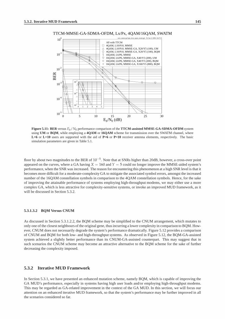
5.3.2. Iterative MUD Framework 145
uxrx_mmse-ga-bqm_ttcm_xqam_swatm.gle Fri Jun 11 2004 16:47:33
0 5 10 15 20 25 30Eb/N0 (dB)
10-5
10-4
10-3
10-2
10-1
100
BE
R
TTCM-MMSE-GA-SDMA-OFDM, Lx/Px, 4QAM/16QAM, SWATM
16QAM, L6/P6, MMSE-GA, X160/Y5 (800), BQM16QAM, L6/P6, MMSE-GA, X40/Y5 (200), BQM16QAM, L6/P6, MMSE-GA, X40/Y5 (200), UM16QAM, L6/P6, MMSE4QAM, L10/P10, MMSE-GA, X20/Y5 (100), BQM4QAM, L10/P10, MMSE-GA, X20/Y5 (100), UM4QAM, L10/P10, MMSEAll with TTCM
0 1 2 3 4 510
-5
2
5
10-4
2
5
10-3
Figure 5.11: BERversusEb/N0 performance comparison of theTTCM-assisted MMSE-GA-SDMA-OFDM systemusingUM or BQM , while employing a4QAM or 16QAM scheme for transmission over the SWATM channel, whereL=6 or L=10 users are supported with the aid ofP=6 or P=10 receiver antenna elements, respectively. The basicsimulation parameters are given in Table 5.1.
floor by about two magnitudes to the BER of10−5. Note that at SNRs higher than 20dB, however, a cross-over pointappeared on the curves, where a GA havingX = 160 andY = 5 could no longer improve the MMSE-aided system’sperformance, when the SNR was increased. The reason for encountering this phenomenon at a high SNR level is that itbecomes more difficult for a moderate-complexity GA to mitigate the associated symbol errors, amongst the increasednumber of the 16QAM constellation symbols in comparison to the 4QAM constellation symbols. Hence, for the sakeof improving the attainable performance of systems employing high-throughput modems, we may either use a morecomplex GA, which is less attractive for complexity-sensitive systems, or invoke an improved MUD framework, as itwill be discussed in Section 5.3.2.
5.3.1.3.2 BQM Versus CNUM
As discussed in Section 5.3.1.2.2, the BQM scheme may be simplified to the CNUM arrangement, which mutates toonly one of the closest neighbours of the original gene, thusincurring a lower complexity in comparison to BQM. How-ever, CNUM does not necessarily degrade the system’s performance dramatically. Figure 5.12 provides a comparisonof CNUM and BQM for both low- and high-throughput systems. Asobserved in Figure 5.12, the BQM-GA-assistedsystem achieved a slightly better performance than its CNUM-GA-assisted counterpart. This may suggest that insuch scenarios the CNUM scheme may become an attractive alternative to the BQM scheme for the sake of furtherdecreasing the complexity imposed.
5.3.2 Iterative MUD Framework
In Section 5.3.1, we have presented an enhanced mutation scheme, namely BQM, which is capable of improving theGA MUD’s performance, especially in systems having high user loads and/or employing high-throughput modems.This may be regarded as GA-related improvement in the context of the GA MUD. In this section, we will focus ourattention on an enhanced iterative MUD framework, so that the system’s performance may be further improved in allthe scenarios considered so far.
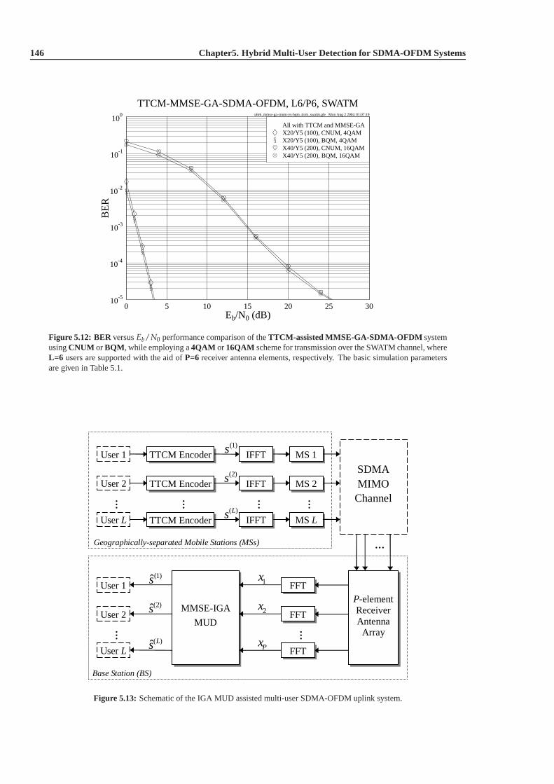
146 Chapter5. Hybrid Multi-User Detection for SDMA-OFDM Systems
u6r6_mmse-ga-cnum-vs-bqm_ttcm_swatm.gle Mon Aug 2 2004 01:07:19
0 5 10 15 20 25 30Eb/N0 (dB)
10-5
10-4
10-3
10-2
10-1
100
BE
RTTCM-MMSE-GA-SDMA-OFDM, L6/P6, SWATM
X40/Y5 (200), BQM, 16QAMX40/Y5 (200), CNUM, 16QAMX20/Y5 (100), BQM, 4QAMX20/Y5 (100), CNUM, 4QAMAll with TTCM and MMSE-GA
Figure 5.12: BERversusEb/N0 performance comparison of theTTCM-assisted MMSE-GA-SDMA-OFDM systemusingCNUM or BQM , while employing a4QAM or 16QAM scheme for transmission over the SWATM channel, whereL=6 users are supported with the aid ofP=6 receiver antenna elements, respectively. The basic simulation parametersare given in Table 5.1.
User 1
MMSE-IGA
MUD
User 2
IFFT (1)s
(2)s
( )Ls
1x
2x
Px
(1)s
(2)s
( )ˆ Ls
User 1 FFT
Base Station (BS)
MS 1
MS 2
Geographically-separated Mobile Stations (MSs)
P-element Receiver Antenna Array
User L
…
…
…
…
…
…
User L FFT
User 2 FFT
IFFT
TTCM Encoder IFFT MS L
TTCM Encoder
TTCM Encoder
…
SDMA MIMO Channel
Figure 5.13: Schematic of the IGA MUD assisted multi-user SDMA-OFDM uplink system.
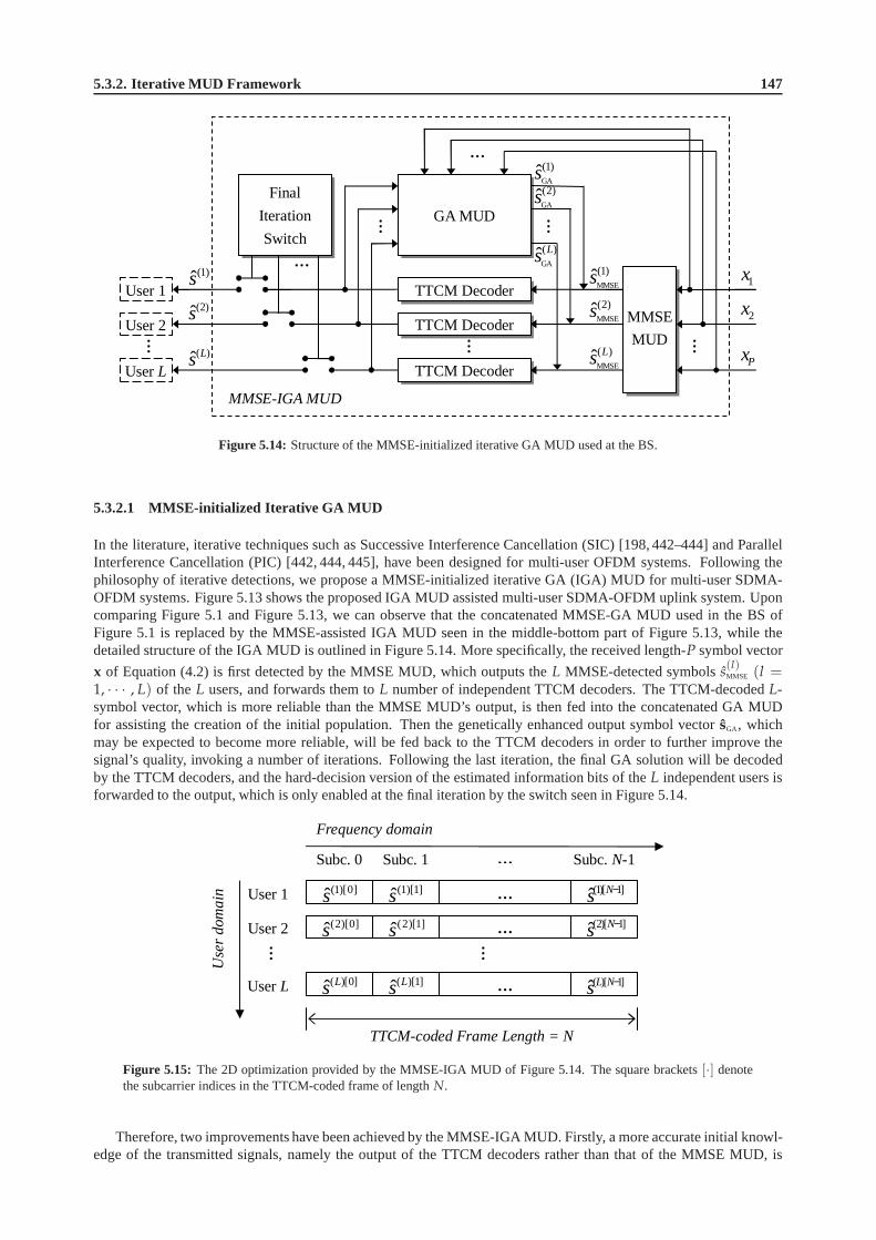
5.3.2. Iterative MUD Framework 147
MMSE-IGA MUD
…
…
…
…
TTCM Decoder
TTCM Decoder
TTCM Decoder
GA MUD
MMSE
MUD
…
User 1
User 2
User L
(1)s(2)s
( )ˆ Ls
1x
2x
Px
Final
Iteration
Switch
MMSE
(1)s…
MMSE
(2)s
MMSE
( )ˆ Ls
GA
(1)s
GA
(2)s
GA
( )ˆ Ls
…
Figure 5.14: Structure of the MMSE-initialized iterative GA MUD used at the BS.
5.3.2.1 MMSE-initialized Iterative GA MUD
In the literature, iterative techniques such as SuccessiveInterference Cancellation (SIC) [198, 442–444] and ParallelInterference Cancellation (PIC) [442, 444, 445], have beendesigned for multi-user OFDM systems. Following thephilosophy of iterative detections, we propose a MMSE-initialized iterative GA (IGA) MUD for multi-user SDMA-OFDM systems. Figure 5.13 shows the proposed IGA MUD assisted multi-user SDMA-OFDM uplink system. Uponcomparing Figure 5.1 and Figure 5.13, we can observe that theconcatenated MMSE-GA MUD used in the BS ofFigure 5.1 is replaced by the MMSE-assisted IGA MUD seen in the middle-bottom part of Figure 5.13, while thedetailed structure of the IGA MUD is outlined in Figure 5.14.More specifically, the received length-P symbol vector
x of Equation (4.2) is first detected by the MMSE MUD, which outputs theL MMSE-detected symbolss(l)MMSE (l =
1, · · · , L) of the L users, and forwards them toL number of independent TTCM decoders. The TTCM-decodedL-symbol vector, which is more reliable than the MMSE MUD’s output, is then fed into the concatenated GA MUDfor assisting the creation of the initial population. Then the genetically enhanced output symbol vectorsGA, whichmay be expected to become more reliable, will be fed back to the TTCM decoders in order to further improve thesignal’s quality, invoking a number of iterations. Following the last iteration, the final GA solution will be decodedby the TTCM decoders, and the hard-decision version of the estimated information bits of theL independent users isforwarded to the output, which is only enabled at the final iteration by the switch seen in Figure 5.14.
User 1
Frequency domain
Use
r d
oma
in
Subc. 0
(1)[0]s
(2)[0]s
( )[0]ˆ Ls
(1)[1]s
(2)[1]s
( )[1]ˆ Ls
…
…
…
…
(1)[ 1]ˆ Ns −
(2)[ 1]ˆ Ns −
( )[ 1]ˆL Ns −
Subc. 1 … Subc. N-1
User 2
User L
TTCM-coded Frame Length = N
…
Figure 5.15: The 2D optimization provided by the MMSE-IGA MUD of Figure 5.14. The square brackets[·] denotethe subcarrier indices in the TTCM-coded frame of lengthN.
Therefore, two improvements have been achieved by the MMSE-IGA MUD. Firstly, a more accurate initial knowl-edge of the transmitted signals, namely the output of the TTCM decoders rather than that of the MMSE MUD, is

148 Chapter5. Hybrid Multi-User Detection for SDMA-OFDM Systems
supplied for the GA MUD. This reliable improvement therefore offers a better starting point for the GA’s search. Sec-ondly, the iterative processing ensures that the detectedL-user symbol vector can be optimized in two dimensions, asdemonstrated in Figure 5.15. During every iteration, on onehand, eachL-symbol vector at a specified subcarrier slotis optimized by the GA in the context of theuser domain. On the other hand, the entire TTCM-coded frame of eachuser is optimized by the TTCM decoder in the context of the TTCM-relatedcodeword domain, or more specificallythe frequency domain. Hence, as the iterative processing continues, an information exchange takes place between thetwo domains, resulting in a 2D optimization which may be expected to improve the system’s performance.
5.3.2.2 Simulation Results
In this section, we combine the IGA MUD with BQM, which has been presented in Section 5.3.1.2, and compare theassociated simulation results with our previous results. Note that for the sake of fairness, we halved the number ofTTCM decoding iterations for the IGA-aided scheme, so that the total TTCM-related complexity remains approxi-mately the same as in the non-iterative system. For the convenience of the reader, in Table 5.5 we summarize the basicsimulation parameters used for generating the results provided in this section.
Modem 4QAM
Code rate 0.5
Code memoryν 3
TTCM Octal generator polynomial [13 6]
Codeword length 1024 symbols
Channel interleaver depth 1024 symbols
Number of turbo iterations 2
Population initialization method MMSE
Mating pool creation strategy Pareto-Optimality
Selection method Fitness-Proportionate
Cross-over Uniform cross-over
Mutation UM or BQM
GA Mutation probabilitypm 0.1
Elitism Enabled
Incest prevention Enabled
Population sizeX Varied
GenerationsY Varied
Number of IGA iterations Varied
CIRs SWATM [5]
Paths 3
Channel Maximum path delay 48.9 ns
Normalized Doppler frequencyfd 1.235 × 10⁻⁵
SubcarriersK 512
Cyclic prefix 64
Table 5.5: The various techniques and parameters used in the simulations of Section 5.3.2.2.
5.3.2.2.1 Performance in Underloaded and Fully-loaded Scenarios
In this section, we will investigate the system’s achievable performance generated in the so-called underloaded andfully-loaded scenarios, respectively, where the number ofusersL is less than or is equal to the number of receiverantennasP.

5.3.2. Iterative MUD Framework 149
5.3.2.2.1.1 BQM-IGA Performance
u6r6_mmse-itr-ga-bqm_ttcm_4qam_swatm.gle Tue Jun 15 2004 23:02:51
0 1 2 3 4 5 6 7 8 9 10Eb/N0 (dB)
10-5
10-4
10-3
10-2
10-1
100
BE
R
TTCM-MMSE-IGA-SDMA-OFDM, L6/P6, 4QAM, SWATM
TTCM, ML (4096)TTCM, MMSE-IGA (2), X20/Y5 (200), BQMTTCM, MMSE-IGA (2), X10/Y5 (100), BQMTTCM, MMSE-IGA (1), X20/Y5 (100), BQMTTCM, MMSE-IGA (1), X20/Y5 (100), UMTTCM, MMSE-GA, X20/Y5 (100), BQMTTCM, MMSE-GA, X20/Y5 (100), UMTTCM, MMSE(L1P6, AWGN)(L1P1, AWGN)
Figure 5.16: BERversusEb/N0 performance comparison of theiterative or non-iterative TTCM-assisted MMSE-GA-SDMA-OFDM system usingUM or BQM , while employing a4QAM scheme for transmission over the SWATMchannel, whereL=6 users are supported with the aid ofP=6 receiver antenna elements, respectively. The basic simula-tion parameters are given in Table 5.5.
Figure 5.16 shows the BER performance achieved by the various schemes considered. The numbers in the roundbrackets seen in the legends of Figure 5.16 denote the associated number of IGA MUD iterations and the total GA orML complexity, respectively. From the results of Figure 5.16 two conclusions may be arrived at. Firstly, an improvedperformance can be achieved, when the GA commences its operation from a better initial population, regardless of thedifferent mutation schemes used. For example, at the same GAcomplexity, the single-iteration IGA MUD assistedsystems outperformed their non-iterative GA aided counterparts, since the initial GA population of the former systemswere created based on the first-iteration outputs of the TTCMdecoders, rather than on the less reliable MMSE MUDregardless, whether UM or BQM was employed.
Secondly, the system employing the BQM-aided two-iteration IGA MUD was capable of achieving the sameperformance as the optimum ML-aided system at an even lower complexity compared to the UM- or BQM-aided non-iterative GA MUD, which was characterized in Figure 5.10. For instance, Figure 5.16 shows that the two-iterationBQM-IGA MUD having a complexity of 200 achieved virtually undistinguishable performance in comparison to itsML-aided counterpart, while the non-iterative UM/BQM-GA MUD having a complexity of 400 attained a slightlyinferior performance in comparison to the ML-aided arrangement, as observed in Figure 5.10.
Having investigated the system using the 4QAM modem, let us now consider various high-throughput scenarios.As mentioned in Section 5.3.1.3, the non-iterative GA MUD may result in a high residual error floor in high-throughputscenarios, even if BQM is employed. However, with the aid of the IGA MUD, the error floor can be effectivelyreduced, as seen in Figure 5.17. 16QAM modem was employed by all the schemes7 characterized in Figure 5.17,except for the uncoded single-user benchmark scheme communicating over the AWGN channel, which used 8PSK forthe sake of maintaining the same effective throughput of 3BPS as the other TTCM-coded schemes. Similarly to the4QAM scenario of Figure 5.16, it can be seen in Figure 5.17 that a better initial population resulted in an improvedperformance in both the UM- and BQM-aided systems. However,we may notice that even when assisted by a reliableinitial knowledge of the transmitted symbols, the UM-aidedsingle-iteration IGA MUD was unable to substantiallydecrease the error floor. Even when we increased the number ofUM-IGA MUD iterations, the situation remainedthe same, except for the modest improvements achieved at SNRs lower than 16dB. By contrast, the BQM-aidedscheme is capable of substantially exploiting the benefits arising from both a better initial GA population and from anincreased number of IGA MUD iterations. More specifically, on one hand, the improved initial population provides a
7Note that in this case the associated complexity of the ML-aided scheme is as high as on the order ofO(2mL) = O(24·6) = O(16, 777, 216),which imposes an excessive complexity and hence cannot be simulated.

150 Chapter5. Hybrid Multi-User Detection for SDMA-OFDM Systems
u6r6_mmse-itr-ga-bqm_ttcm_16qam_swatm.gle Mon Jul 12 2004 20:01:50
0 5 10 15 20 25 30Eb/N0 (dB)
10-5
10-4
10-3
10-2
10-1
100
BE
R
TTCM-MMSE-IGA-SDMA-OFDM, L6/P6, 16QAM, SWATM
TTCM, MMSE-IGA (4), X40/Y5 (800), BQMTTCM, MMSE-IGA (2), X40/Y5 (400), BQMTTCM, MMSE-IGA (2), X40/Y5 (400), UMTTCM, MMSE-IGA (1), X40/Y5 (200), BQMTTCM, MMSE-IGA (1), X40/Y5 (200), UMTTCM, MMSE-GA, X40/Y5 (200), BQMTTCM, MMSE-GA, X40/Y5 (200), UMTTCM, MMSE(L1P1, AWGN)
Figure 5.17: BERversusEb/N0 performance comparison of theiterative or non-iterative TTCM-assisted MMSE-GA-SDMA-OFDM system usingUM or BQM , while employing a16QAM scheme for transmission over the SWATMchannel, whereL=6 users are supported with the aid ofP=6 receiver antenna elements, respectively. The basic simula-tion parameters are given in Table 5.5.
good starting point for the GA, thus assisting the BQM, whichin turn benefits the entire detection process, resultingin a substantial performance improvement. On the other hand, the iterative processing invoked by the IGA MUDfurther enhances the system’s performance with the aid of the 2D optimization, as discussed in Section 5.3.2.1, sincethe beneficial information exchange between the user domainand the frequency domain assists both the GA MUDand the TTCM decoder in eliminating more and more errors found in the received signal, as the iterative procedurecontinues.
5.3.2.2.1.2 Effects of the Number of IGA MUD Iterations
Figure 5.18 shows theEb/N0 gain achieved by the BQM-IGA assisted TTCM-MMSE-SDMA-OFDMsystems em-ploying 16QAM at the BER of10−5, while using different number of IGA MUD iterations. TheEb/N0 gain isdefined here as theEb/N0 difference measured at the BER of10−5 between the systems employing the BQM-IGAMUD or the MMSE MUD. As expected, when we had a higher number ofIGA MUD iterations, a higherEb/N0 gainwas attained. It is also found in Figure 5.18 that most of the achievable gain may be attained, when the number of IGAMUD iterations reaches 8. Furthermore, when the complexityof the GA MUD increases, because for example a higherpopulation size is employed, a higher gain can be achieved, as seen in Figure 5.18. Moreover, we may also noticethat when the number of IGA MUD iterations was increased, thedifference between theEb/N0 gains achieved by thehigher-complexity and the lower-complexity IGAs tends to be larger. For example, as observed in Figure 5.18, whenwe had only one IGA MUD iteration, theEb/N0 gain difference between the two curves was about 1dB, while thisvalue increased to about 3dB, when the number of iterations was increased to 8. This suggests that a high-complexityIGA may benefit more from a higher number of IGA MUD iterationsthan its lower-complexity counterpart.
5.3.2.2.1.3 Effects of the User Load
Figure 5.19 exhibits the correspondingEb/N0 gains achieved by the SDMA-OFDM system exploitingP = 6 receiverantenna elements at the BER of10−5 in the scenarios, where the user load varies. The user load ofSDMA-OFDMsystems was defined by Equation (4.14) in Section 4.3.2.1.1.As observed in Figure 5.19, firstly, it is shown thatwhen the user load becomes higher, a higher gain can be attained. For example, for the single-iteration IGA-aidedsystem, a further gain of about 3.5dB is achieved, when the number of users increases from four to six. This is becausewhen more users were accommodated by the SDMA-OFDM system, the reference MMSE MUD suffered a higher

5.3.2. Iterative MUD Framework 151
itr-gain_u6r6_mmse-itrx-ga-bqm_ttcm_16qam_swatm.gle Mon Oct 24 2005 14:32:08
1 2 3 4 5 6 7 8Number of Iterations
3
4
5
6
7
8
9
10
11
12
Itera
tion
Gai
n(d
B)
TTCM-MMSE-IGA-SDMA-OFDM, L6/P6, 16QAM, SWATM
TTCM, MMSE-IGA, X40/Y5, BQMTTCM, MMSE-IGA, X20/Y5, BQM
Figure 5.18: Iteration gain at the BER of10−5 versus number of IGA MUD iterations performance of theTTCM-assisted MMSE-IGA-SDMA-OFDM system usingBQM , while employing a16QAM scheme for transmission overthe SWATM channel, whereL=6 users are supported with the aid ofP=6receiver antenna elements. The basic simulationparameters are given in Table 5.5.
gain-vs-usr_u6r6_mmse-itrx-ga-bqm_ttcm_16qam_swatm.gle Sat Jul 24 2004 01:23:40
4 5 6Number of Users
0
1
2
3
4
5
6
7
8
Eb/
N0
Gai
n(d
B)
TTCM-MMSE-IGA-SDMA-OFDM, Lx/P6, 16QAM, SWATM
TTCM, MMSE-IGA (2), X40/Y5, BQMTTCM, MMSE-IGA (1), X40/Y5, BQM
Figure 5.19: Eb/N0 gain at the BER of10−5 versus number of users performance of theTTCM-assisted MMSE-IGA-SDMA-OFDM system usingBQM , while employing a16QAM scheme for transmission over the SWATM chan-nel, whereL=4, 5, 6users are supported with the aid ofP=6 receiver antenna elements, respectively. The basic simula-tion parameters are given in Table 5.5.
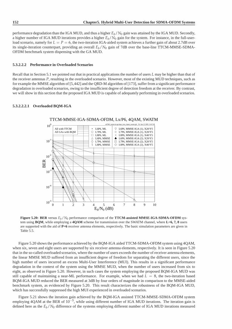
152 Chapter5. Hybrid Multi-User Detection for SDMA-OFDM Systems
performance degradation than the IGA MUD, and thus a higherEb/N0 gain was attained by the IGA MUD. Secondly,a higher number of IGA MUD iterations provides a higherEb/N0 gain for the system. For instance, in the full-user-load scenario, namely forL = P = 6, the two-iteration IGA-aided system achieves a further gain of about 2.7dB overits single-iteration counterpart, providing an overallEb/N0 gain of 7dB over the base-line TTCM-MMSE-SDMA-OFDM benchmark system dispensing with the GA MUD.
5.3.2.2.2 Performance in Overloaded Scenarios
Recall that in Section 5.1 we pointed out that in practical applications the number of usersL may be higher than that ofthe receiver antennasP, resulting in the overloaded scenario. However, most of theexisting MUD techniques, such asfor example the MMSE algorithm of [5,442] and the QRD-M algorithm of [173], suffer from a significant performancedegradation in overloaded scenarios, owing to the insufficient degree of detection freedom at the receiver. By contrast,we will show in this section that the proposed IGA MUD is capable of adequately performing in overloaded scenarios.
5.3.2.2.2.1 Overloaded BQM-IGA
u678r6_mmse-itr-ga-bqm_ttcm_4qam_swatm.gle Fri Apr 22 2005 14:47:48
0 1 2 3 4 5 6 7 8 9 10Eb/N0 (dB)
10-5
10-4
10-3
10-2
10-1
100
BE
R
TTCM-MMSE-IGA-SDMA-OFDM, Lx/P6, 4QAM, SWATM
All GAs with BQMAll with TTCM
L8P6, MMSEL7P6, MMSEL6P6, MMSEL8P6, MLL7P6, MLL6P6, ML
L8P6, MMSE-IGA (2), X40/Y5L7P6, MMSE-IGA (2), X20/Y5L6P6, MMSE-IGA (2), X20/Y5L8P6, MMSE-IGA (1), X40/Y5L7P6, MMSE-IGA (1), X20/Y5L6P6, MMSE-IGA (1), X20/Y5
Figure 5.20: BER versusEb/N0 performance comparison of theTTCM-assisted MMSE-IGA-SDMA-OFDM sys-tem usingBQM , while employing a4QAM scheme for transmission over the SWATM channel, whereL=6, 7, 8usersare supported with the aid ofP=6 receiver antenna elements, respectively. The basic simulation parameters are given inTable 5.5.
Figure 5.20 shows the performance achieved by the BQM-IGA aided TTCM-SDMA-OFDM system using 4QAM,when six, seven and eight users are supported by six receiverantenna elements, respectively. It is seen in Figure 5.20that in the so-called overloaded scenarios, where the number of users exceeds the number of receiver antenna elements,the linear MMSE MUD suffered from an insufficient degree of freedom for separating the different users, since thehigh number of users incurred an excess Multi-User Interference (MUI). This results in a significant performancedegradation in the context of the system using the MMSE MUD, when the number of users increased from six toeight, as observed in Figure 5.20. However, in such cases thesystem employing the proposed BQM-IGA MUD wasstill capable of maintaining a near-ML performance. For example, when we hadL = 8, the two-iteration basedBQM-IGA MUD reduced the BER measured at 3dB by four orders of magnitude in comparison to the MMSE-aidedbenchmark system, as evidenced by Figure 5.20. This result characterizes the robustness of the BQM-IGA MUD,which has successfully suppressed the high MUI experiencedin overloaded scenarios.
Figure 5.21 shows the iteration gain achieved by the BQM-IGAassisted TTCM-MMSE-SDMA-OFDM systememploying 4QAM at the BER of10−5, while using different number of IGA MUD iterations. The iteration gain isdefined here as theEb/N0 difference of the systems employing different number of IGAMUD iterations measured
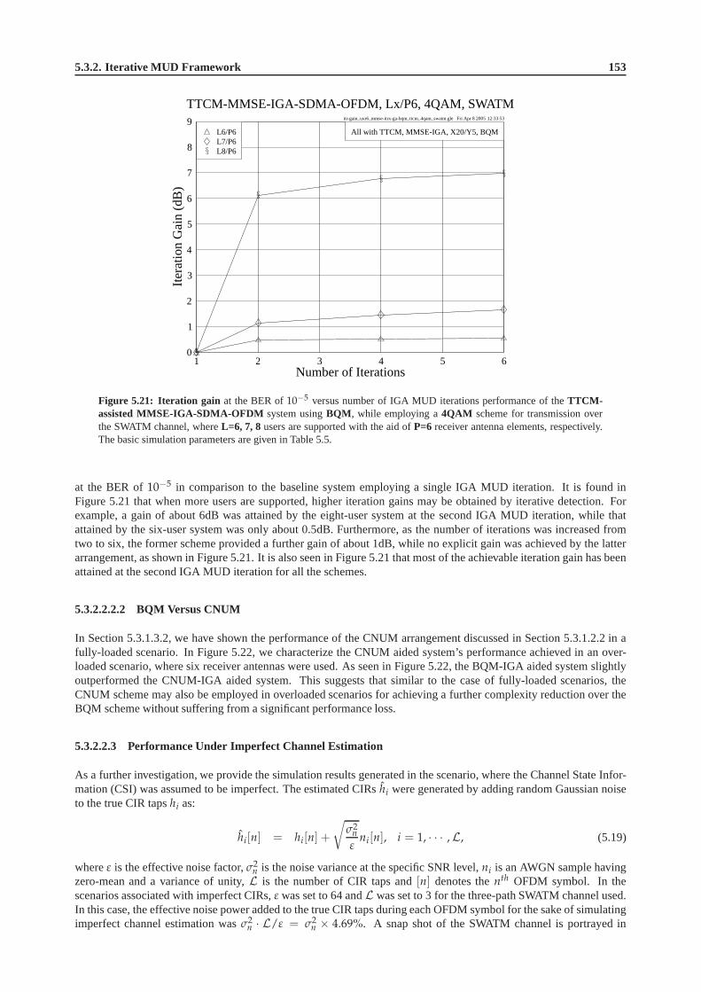
5.3.2. Iterative MUD Framework 153
itr-gain_uxr6_mmse-itrx-ga-bqm_ttcm_4qam_swatm.gle Fri Apr 8 2005 12:33:53
1 2 3 4 5 6Number of Iterations
0
1
2
3
4
5
6
7
8
9
Itera
tion
Gai
n(d
B)
TTCM-MMSE-IGA-SDMA-OFDM, Lx/P6, 4QAM, SWATM
L8/P6L7/P6L6/P6 All with TTCM, MMSE-IGA, X20/Y5, BQM
Figure 5.21: Iteration gain at the BER of10−5 versus number of IGA MUD iterations performance of theTTCM-assisted MMSE-IGA-SDMA-OFDM system usingBQM , while employing a4QAM scheme for transmission overthe SWATM channel, whereL=6, 7, 8 users are supported with the aid ofP=6 receiver antenna elements, respectively.The basic simulation parameters are given in Table 5.5.
at the BER of10−5 in comparison to the baseline system employing a single IGA MUD iteration. It is found inFigure 5.21 that when more users are supported, higher iteration gains may be obtained by iterative detection. Forexample, a gain of about 6dB was attained by the eight-user system at the second IGA MUD iteration, while thatattained by the six-user system was only about 0.5dB. Furthermore, as the number of iterations was increased fromtwo to six, the former scheme provided a further gain of about1dB, while no explicit gain was achieved by the latterarrangement, as shown in Figure 5.21. It is also seen in Figure 5.21 that most of the achievable iteration gain has beenattained at the second IGA MUD iteration for all the schemes.
5.3.2.2.2.2 BQM Versus CNUM
In Section 5.3.1.3.2, we have shown the performance of the CNUM arrangement discussed in Section 5.3.1.2.2 in afully-loaded scenario. In Figure 5.22, we characterize theCNUM aided system’s performance achieved in an over-loaded scenario, where six receiver antennas were used. As seen in Figure 5.22, the BQM-IGA aided system slightlyoutperformed the CNUM-IGA aided system. This suggests thatsimilar to the case of fully-loaded scenarios, theCNUM scheme may also be employed in overloaded scenarios forachieving a further complexity reduction over theBQM scheme without suffering from a significant performanceloss.
5.3.2.2.3 Performance Under Imperfect Channel Estimation
As a further investigation, we provide the simulation results generated in the scenario, where the Channel State Infor-mation (CSI) was assumed to be imperfect. The estimated CIRshi were generated by adding random Gaussian noiseto the true CIR tapshi as:
hi[n] = hi[n] +
√
σ2n
εni[n], i = 1, · · · ,L, (5.19)
whereε is the effective noise factor,σ2n is the noise variance at the specific SNR level,ni is an AWGN sample having
zero-mean and a variance of unity,L is the number of CIR taps and[n] denotes thenth OFDM symbol. In thescenarios associated with imperfect CIRs,ε was set to 64 andL was set to 3 for the three-path SWATM channel used.In this case, the effective noise power added to the true CIR taps during each OFDM symbol for the sake of simulatingimperfect channel estimation wasσ2
n · L/ε = σ2n × 4.69%. A snap shot of the SWATM channel is portrayed in
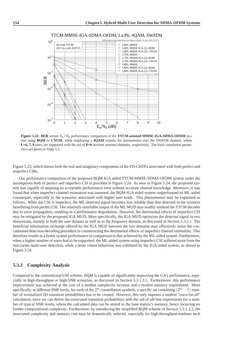
154 Chapter5. Hybrid Multi-User Detection for SDMA-OFDM Systems
u678r6_bqm-vs-cnum_mmse-itr-ga_ttcm_4qam_swatm.gle Sat Apr 9 2005 16:47:56
0 1 2 3 4 5 6 7 8 9 10Eb/N0 (dB)
10-5
10-4
10-3
10-2
10-1
100
BE
R
TTCM-MMSE-IGA-SDMA-OFDM, Lx/P6, 4QAM, SWATM
L8P6, MMSE-IGA (2), CNUML8P6, MMSE-IGA (2), BQML8P6, MMSEL7P6, MMSE-IGA (2), CNUML7P6, MMSE-IGA (2), BQML7P6, MMSEL6P6, MMSE-IGA (2), CNUML6P6, MMSE-IGA (2), BQML6P6, MMSE
All GAs with X20/Y5All with TTCM
Figure 5.22: BER versusEb/N0 performance comparison of theTTCM-assisted MMSE-IGA-SDMA-OFDM sys-tem usingBQM or CNUM , while employing a4QAM scheme for transmission over the SWATM channel, whereL=6, 7, 8users are supported with the aid ofP=6 receiver antenna elements, respectively. The basic simulation param-eters are given in Table 5.5.
Figure 5.23, which shows both the real and imaginary components of the FD-CHTFs associated with both perfect andimperfect CIRs.
Our performance comparison of the proposed BQM-IGA aided TTCM-MMSE-SDMA-OFDM system under theassumptions both of perfect and imperfect CSI is provided inFigure 5.24. As seen in Figure 5.24, the proposed sys-tem was capable of attaining an acceptable performance evenwithout accurate channel knowledge. Moreover, it wasfound that when imperfect channel estimation was assumed, the BQM-IGA aided system outperformed its ML-aidedcounterpart, especially in the scenarios associated with higher user loads. This phenomenon may be explained asfollows. When the CSI is imperfect, the ML-detected signal becomes less reliable than that detected in the scenariobenefitting from perfect CSI. The relatively unreliable output of the ML MUD may readily mislead the TTCM decoderdue to error propagation, resulting in a performance degradation. However, the detrimental effects of imperfect CSImay be mitigated by the proposed IGA MUD. More specifically, the IGA MUD optimizes the detected signal in twodimensions, namely in both the user domain as well as in the frequency domain, as discussed in Section 5.3.2.1. Thebeneficial information exchange offered by the IGA MUD between the two domains may effectively assist the con-catenated detection-decoding procedure in counteractingthe detrimental effects of imperfect channel estimation. Thistherefore results in a better system performance in comparison to that achieved by the ML-aided system. Furthermore,when a higher number of users had to be supported, the ML-aided system using imperfect CSI suffered more from theinaccurate multi-user detection, while a more robust behaviour was exhibited by the IGA-aided system, as shown inFigure 5.24.
5.3.3 Complexity Analysis
Compared to the conventional UM scheme, BQM is capable of significantly improving the GA’s performance, espe-cially in high-throughput or high-SNR scenarios, as discussed in Section 5.3.1.3.1. Furthermore, this performanceimprovement was achieved at the cost of a modest complexity increase and a modest memory requirement. Morespecifically, at different SNR levels, for each of the2m constellation symbols, a specific set containing(2m − 1) num-ber of normalized 2D transition probabilities has to be created. However, this only imposes a modest “once-for-all”calculation, since we can derive the associated transitionprobabilities with the aid of off-line experiments for a num-ber of typical SNR levels, where the calculated data can be stored in the base station’s memory, hence incurring nofurther computational complexity. Furthermore, by introducing the simplified BQM scheme of Section 5.3.1.2.2, theassociated complexity and memory cost may be dramatically reduced, especially for high-throughput modems such

5.3.3. Complexity Analysis 155
chtf_swatm_2d_real_imag.gle Tue Mar 22 2005 15:15:15
0 100 200 300 400 500Subcarrier Index
-2.0
-1.5
-1.0
-0.5
0.0
0.5
1.0
1.5
2.0
Rea
l
Channel Transfer Functions, SWATM
ImperfectPerfect
Eb/N0=0dB
0 100 200 300 400 500Subcarrier Index
-2.0
-1.5
-1.0
-0.5
0.0
0.5
1.0
1.5
2.0
Imag
inar
y
Channel Transfer Functions, SWATM
ImperfectPerfect
Eb/N0=0dB
Figure 5.23: The real and imaginary components of the FD-CHTFs of the SWATM channel measured during oneOFDM symbol at aEb/N0 value of 0dB in terms of both perfect and imperfect CIRs.
u678r6i_mmse-itr-ga-bqm_ttcm_4qam_swatm.gle Fri Apr 22 2005 14:48:37
0 1 2 3 4 5 6 7 8 9 10Eb/N0 (dB)
10-5
10-4
10-3
10-2
10-1
100
BE
R
TTCM-MMSE-IGA-SDMA-OFDM, Lx/P6, 4QAM, SWATM
L8P6, MMSE-IGA (2), X40/Y5L8P6, MLL7P6, MMSE-IGA (2), X20/Y5L7P6, MLL6P6, MMSE-IGA (2), X20/Y5L6P6, MLPerfect CSI
L8P6, MMSE-IGA (2), X40/Y5L8P6, MLL7P6, MMSE-IGA (2), X20/Y5L7P6, MLL6P6, MMSE-IGA (2), X20/Y5L6P6, MLImperfect CSI
Imperfect CSIPerfect CSIAll GAs with BQMAll with TTCM
Figure 5.24: BER versusEb/N0 performance comparison of theTTCM-assisted MMSE-IGA-SDMA-OFDM sys-tem usingBQM with perfect or imperfect CSI , while employing a4QAM scheme for transmission over the SWATMchannel, whereL=6, 7, 8 users are supported with the aid ofP=6 receiver antenna elements, respectively. The basicsimulation parameters are given in Table 5.5.

156 Chapter5. Hybrid Multi-User Detection for SDMA-OFDM Systems
as 16QAM or 64QAM, since the number of mutation target candidates decreases and thus fewer transition probabilitycalculations are required. Moreover, if the CNUM scheme is employed, the associated complexity can be furtherdecreased, since in this case there is no need to calculate the transition probabilities, which are already available inTable 5.4. This may significantly reduce the associated complexity and memory requirement, while still maintaininga similar performance to that of the BQM scheme, as seen in Figures 5.12 and 5.22.
comp-vs-ebn0_u8r6_ml_mmse_iga.gle Sun Apr 10 2005 20:05:34
0 2 4 6 8 10Eb/N0 (dB)
101
102
103
104
105
106
107
108
109
Add
ition
s+
Mul
tiplic
atio
nspe
rU
ser
TTCM-MMSE-IGA-SDMA-OFDM, L8/P6, 4QAM, SWATM
MMSE-IGA (2), X40/Y5MMSE-IGA (6), X20/Y5MMSE-IGA (4), X20/Y5MMSE-IGA (2), X20/Y5MMSE-IGA (1), X20/Y5MMSEML
All GAs with BQMAll with TTCM
Figure 5.25: Complexity per user versusEb/N0 performance comparison of theTTCM-assisted MMSE-SDMA-OFDM , ML-SDMA-OFDM , andMMSE-BQM-IGA-SDMA-OFDM systems, while employing a4QAM scheme fortransmission over the SWATM channel, whereL=8 users are supported with the aid ofP=6 receiver antenna elements.The basic simulation parameters are given in Table 5.5.
As shown in Figures 5.18 and 5.21, the system’s performance can be further improved, when the number of IGAMUD iterations is increased. When the other parameters remain the same, using a higher number of IGA MUDiterations will result in a further increased complexity. However, this may still be significantly lower than that imposedby the ML-aided scheme. Figure 5.25 provides our comparisonof the TTCM-assisted MMSE-SDMA-OFDM, ML-SDMA-OFDM and MMSE-BQM-IGA-SDMA-OFDM systems in the context of their MUD complexity, which wasquantified in terms of the number of complex additions and multiplications imposed by the different MUDs on aper user basis. As illustrated in Figure 5.25, the complexity of the ML MUD is significantly higher than that of theMMSE MUD or the IGA MUD. Furthermore, the IGA MUD’s complexity does not significantly vary at differentEb/N0 values and depends on the number of IGA MUD iterations as wellas on the GA’s parameters, for examplethe population size. In Figure 5.26 the complexity of the various systems is compared in terms of different userloads at anEb/N0 value of 0dB. At a specific user load, we always select an appropriate GA-aided scheme forcomparison, which achieved a similar performance comparedto the ML-aided system at the BER of10−5. As seen inFigure 5.26, the ML-aided system imposes a linearly increasing complexity on a logarithmic scale, which correspondsto an exponential increase when the number of users increases. By contrast, the complexity of the IGA-aided systemrequired for maintaining a near-optimum performance increases only moderately.
In order to characterize the advantage of the BQM-IGA schemein terms of the performance-versus-complexitytradeoff, in Table 5.6 we summarize the computational complexity imposed by the different MUDs assuming anEb/N0 value of 3dB. As observed in Table 5.6, the complexity of the ML MUD is significantly higher than that of theMMSE MUD or the IGA MUD, especially in highly overloaded scenarios. By contrast, the IGA MUD reduced theBER by up to five orders of magnitude in comparison to the MMSE MUD at a moderate complexity.
5.3.4 Conclusions
In Sections 5.3.1 and 5.3.2 we proposed specific techniques designed for further enhancing the achievable performanceof the TTCM-assisted MMSE-GA-SDMA-OFDM system. The novel BQM scheme is capable of improving the GA’s
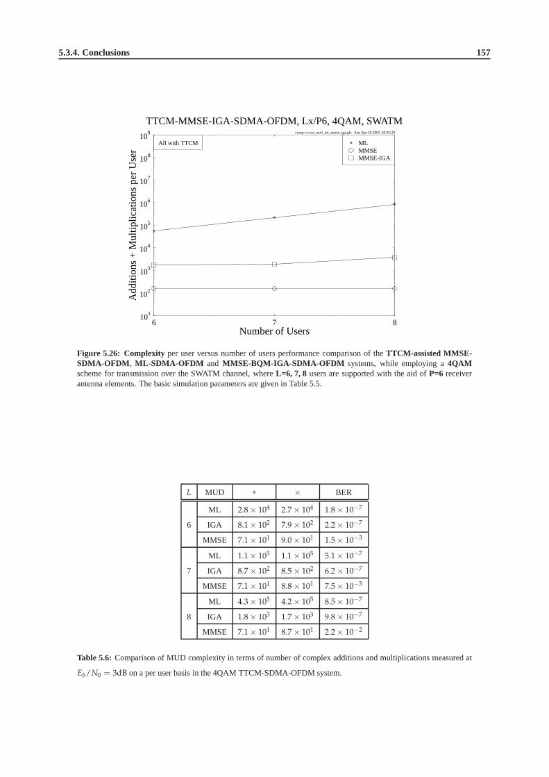
5.3.4. Conclusions 157
comp-vs-usr_uxr6_ml_mmse_iga.gle Sun Apr 10 2005 20:05:29
6 7 8Number of Users
101
102
103
104
105
106
107
108
109
Add
ition
s+
Mul
tiplic
atio
nspe
rU
ser
TTCM-MMSE-IGA-SDMA-OFDM, Lx/P6, 4QAM, SWATM
MMSE-IGAMMSEMLAll with TTCM
Figure 5.26: Complexity per user versus number of users performance comparison of the TTCM-assisted MMSE-SDMA-OFDM , ML-SDMA-OFDM and MMSE-BQM-IGA-SDMA-OFDM systems, while employing a4QAMscheme for transmission over the SWATM channel, whereL=6, 7, 8 users are supported with the aid ofP=6 receiverantenna elements. The basic simulation parameters are given in Table 5.5.
L MUD + × BER
ML 2.8 × 10⁴ 2.7 × 10⁴ 1.8 × 10⁻⁷
6 IGA 8.1 × 10² 7.9 × 10² 2.2 × 10⁻⁷
MMSE 7.1 × 101 9.0 × 101 1.5 × 10⁻³
ML 1.1 × 10⁵ 1.1 × 10⁵ 5.1 × 10⁻⁷
7 IGA 8.7 × 10² 8.5 × 10² 6.2 × 10⁻⁷
MMSE 7.1 × 101 8.8 × 101 7.5 × 10⁻³
ML 4.3 × 10⁵ 4.2 × 10⁵ 8.5 × 10⁻⁷
8 IGA 1.8 × 10³ 1.7 × 10³ 9.8 × 10⁻⁷
MMSE 7.1 × 101 8.7 × 101 2.2 × 10⁻²
Table 5.6: Comparison of MUD complexity in terms of number of complex additions and multiplications measured at
Eb/N0 = 3dB on a per user basis in the 4QAM TTCM-SDMA-OFDM system.

158 Chapter5. Hybrid Multi-User Detection for SDMA-OFDM Systems
search at a modest complexity increase, thus significantly increasing the chances of finding the optimum GA solutionin high-SNR and/or high-throughput scenarios. On the otherhand, the 2D optimization provided by the proposedIGA MUD has been shown to be beneficial for the SDMA-OFDM system in both the frequency and user domains.Finally, the scheme that combines BQM with the IGA MUD yieldsthe best and near-optimum performance in allscenarios considered, including the so-called overloadedscenario, where the performance of most of the conventionaldetection techniques such as the classic linear MMSE MUD significantly degrades, owing to the insufficiently highdegree of freedom. Furthermore, this superior performanceof the proposed scheme is achieved at a significantly lowercomputational complexity than that imposed by the ML-assisted system, especially when the number of users is high.For example, a complexity reduction of three orders of magnitude can be achieved by the proposed BQM-IGA aidedsystem in the overloaded scenario associated withL = 8, as evidenced by Figure 5.26. Moreover, we demonstrate thatthe proposed scheme is capable of providing a satisfactory performance even when the channel estimation is imperfect.
5.4 Chapter Summary
In this chapter, we proposed a TTCM-assisted MMSE-GA MUD designed for SDMA-OFDM systems. In Sec-tion 5.2.1 we provided a system overview of the proposed GA-assisted TTCM-MMSE-SDMA-OFDM system. Theoptimization metric designed for the proposed GA MUD was described in Section 5.2.2.1. Section 5.2.2.2 outlined theconcatenated MMSE-GA MUD, while its performance was evaluated in Section 5.2.3, where the GA-based schemeswere shown to be capable of achieving a near-optimum performance. Furthermore, a complexity comparison be-tween the proposed GA MUD and the optimum ML MUD was provided in Section 5.2.4, where we showed that thecomplexity of the GA MUD was significantly lower than that of the ML MUD.
For the sake of further improving the performance of the TTCM-assisted MMSE-GA-SDMA-OFDM system, anenhanced GA MUD was proposed in Section 5.3. This was described in two steps. Firstly, the novel BQM scheme wasproposed in Section 5.3.1, including a review of the conventional UM scheme, followed by the detailed explanationof the BQM mechanism, which were the subjects of Sections 5.3.1.1 and 5.3.1.2, respectively. The BQM-aided GAMUD exploits an effective mutation strategy and thus it is capable of achieving a better performance in comparisonto its UM-aided counterpart, especially at high SNRs or highuser loads, as evidenced by the simulation results givenin Section 5.3.1.3. Moreover, this was achieved at a modest complexity increase. Secondly, a MMSE-initialized IGAMUD was introduced in Section 5.3.2. The theoretical foundations of the IGA MUD were presented in Section 5.3.2.1,where the IGA framework as well as its optimization capability were characterized. Our related simulation results wereprovided in Section 5.3.2.2, where the combined BQM-IGA assisted system was found to give the best performancein all scenarios considered, while maintaining a modest computational complexity. In low-throughput scenarios, forexample a six-user system employing a 4QAM modem, a two-iteration BQM-IGA MUD associated withX = 20andY = 5 was capable of achieving the same performance as the optimumML-aided system at a complexity of200, which is only about 50% and 5% of the MUD-related complexity imposed by the conventional UM-aided single-iteration IGA MUD and the optimum ML MUD, respectively. On the other hand, in high-throughput six-user systemsemploying for example a 16QAM modem, a two-iteration BQM-IGA MUD associated withX = 40 andY = 5achieved anEb/N0 gain of about 7dB over the MMSE MUD benchmarker at the BER of10−5, while the UM-aided GA or IGA MUDs suffered from a high residual error floor even when the iterative framework was employed.Furthermore, the associatedEb/N0 gain was attained at a modest complexity of 400, which is only0.00238% of theexcessive complexity imposed by the ML MUD that cannot be simulated in this case.
Moreover, the proposed BQM-IGA MUD is capable of providing anear-optimum performance even in the so-called overloaded scenarios, where the number of users is higher than the number of receiver antenna elements, whilemany conventional detection techniques suffer from an excessively high error floor. For example, when we hadL = 8users andP = 6 receivers, the two-iteration based BQM-IGA MUD reduced theBER recorded at anEb/N0 valueof 3dB by four orders of magnitude in comparison to the classic MMSE MUD aided benchmarker system, as shownin Figure 5.20. This result characterizes the robustness ofthe BQM-IGA MUD, which has successfully suppressedthe high MUI experienced in overloaded scenarios. As a further investigation, we demonstrated in Section 5.3.2.2.3that the proposed system is capable of achieving a satisfactory performance even in the case of imperfect channelestimation. Furthermore, the complexity of the proposed detection scheme is only moderately higher than that imposedby the linear MMSE MUD, and is substantially lower than that imposed by the optimum ML MUD, as discussed inSection 5.3.3. We also showed that in both the fully-loaded scenario of Section 5.3.1.3.2 and in the overloaded scenarioof Section 5.3.2.2.2.2 the complexity of the BQM approach can be further reduced by employing its simplified version,namely the CNUM scheme of Section 5.3.1.2.2, at the cost of a slightly degraded system performance.
Note that the system parameters of the IGA framework, such asthe number of TTCM iterations, the number of IGAMUD iterations and the GA-related parameter settings, are all readily configurable, enabling us to strike an attractive
5.4. Chapter Summary 159
tradeoff between the achievable performance and the complexity imposed. For specific scenarios, the TTCM schemeused in the system can also be conveniently substituted by other FEC schemes, for example the TC codes. Therefore,the facility provided by the proposed IGA MUD may make it possible to applications in multi-mode terminals, wheregood performance, low complexity and easy flexibility are all important criterions. It is also worth pointing out thatthe proposed BQM-aided IGA MUD can be readily incorporated into the multi-user CDMA systems, for examplethose of [40]. In this case, the initial detected signal supplied to the GA MUD for creating the first GA populationis provided by the bank of matched filters installed at the CDMA BS, rather than by the MMSE MUD. However, theBQM scheme may remain unchanged.
In the next chapter, our attention will be focused on a TTCM-assisted MMSE-IGA multi-user detected SDMA-OFDM system employing a new type of Frequency-Hopping (FH) technique for the sake of achieving further perfor-mance enhancements.

160 Chapter5. Hybrid Multi-User Detection for SDMA-OFDM Systems
Chapter6Direct-Sequence Spreading and SlowSubcarrier-Hopping Aided Multi-UserSDMA-OFDM Systems
6.1 Conventional SDMA-OFDM Systems
In Chapters 4 and 5, Coded Modulation (CM) [359] assisted SDMA-OFDM systems invoking both Minimum Mean-Square Error (MMSE) and Genetic Algorithm (GA) based Multi-User Detection (MUD) have been investigated, re-spectively. Specifically, in terms of the bandwidth sharingstrategy the SDMA-OFDM systems discussed in thesechapters are referred to here as theconventionalSDMA-OFDM systems [5,194], where all the users exploit the entiresystem bandwidth for their communications. However, this bandwidth sharing strategy exhibits a few drawbacks.
On one hand, the conventional SDMA-OFDM systems can exploitlittle frequency diversity, since each user ac-tivates all available subcarriers. This limitation can be mitigated by combining both Frequency-Hopping (FH) andSDMA-OFDM techniques, resulting in the FH/SDMA-OFDM systems. In FH/SDMA-OFDM systems the total sys-tem bandwidth is divided into several sub-bands, each of which hosts a number of consecutive subcarriers, and aso-called FH pattern is used for controlling the sub-band allocation for the different users. Since each user activatesdifferent sub-bands from time to time, the achievable frequency diversity improves, as the width of the sub-bands isreduced.
On the other hand, when the number of users becomes higher in conventional SDMA-OFDM systems, a higherMulti-User Interference (MUI) is expected across the entire bandwidth and hence all users will suffer from a perfor-mance degradation. Unfortunately, the same phenomenon is encountered also in FH/SDMA-OFDM systems at thosesub-bands that are shared by excessive number of users. Undoubtedly, the best solution to eliminate the MUI is toavoid sub-band collisions between the different users by assigning each sub-band exclusively to a single user. This“one-subband-for-one-user” scheme will inevitably reduce the system’s overall throughput. The attainable systemthroughput can be increased with the aid of higher-order modems, which are more vulnerable to transmission errorsas well as impose an increased MUD complexity at the receivers, which is undesirable. Therefore, subcarrier-reusebased SDMA-OFDM using efficient frequency-hopping techniques is preferable, since it is capable of maintaininga sufficiently high overall system throughput even with the employment of a relatively low-order, low-complexitymodem, while effectively suppressing the associated high MUI.
In this chapter, we will introduce a new bandwidth-efficientapproach for employment in SDMA-OFDM systemsdesigned for solving the two problems mentioned above.
6.2 Introduction to Hybrid SDMA-OFDM
During last decades, a range of Time Division Multiple Access (TDMA) [38], Frequency Division Multiple Access(FDMA) [38] and Code Division Multiple Access (CDMA) [39–43] schemes have found employment in the first-,


![Coherent Detection of Turbo-Coded OFDM Signals … · an OFDM frame when it is not present) ... synchronization for OFDM are given in [15]– ... Detection of OFDM signals,](https://img.dokumen.tips/doc/110x75/5ae5fd777f8b9a08778c6dfc/coherent-detection-of-turbo-coded-ofdm-signals-ofdm-frame-when-it-is-not-present.jpg)


![Coherent optical OFDM: has its time come? [Invited] · There has been growing interest in coherent optical orthogonal frequency-division multiplexing (CO-OFDM). We aim to present](https://img.dokumen.tips/doc/110x75/5e44ecc625ebb67cc04f95c1/coherent-optical-ofdm-has-its-time-come-invited-there-has-been-growing-interest.jpg)