Embed Size (px)
Citation preview

MIMO III: Channel Capacity,Interference Alignment
COS 463: Wireless NetworksLecture 18
Kyle Jamieson
[Parts adapted from D. Tse]

1. Interference Channel Capacity– Single-Antenna Context
2. MIMO Channel Capacity
3. Interference Alignment
Today
2

Two-User Interference Channel
• On the same frequency channel at the same time:– Sender 1 sends signal x1 with power P1– Sender 2 sends signal x2 with power P2
• AP receives: y[m] = x1[m] + x2[m] + w[m]– w[m] is background Gaussian Noise with variance σ2
• What are the fundamental limits of communication here?
Sender 1 Sender 2AP
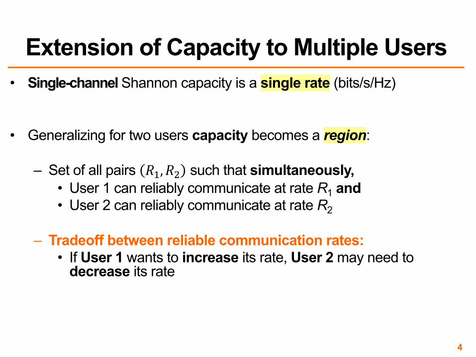
• Single-channel Shannon capacity is a single rate (bits/s/Hz)
• Generalizing for two users capacity becomes a region:
– Set of all pairs !",!$ such that simultaneously,• User 1 can reliably communicate at rate R1 and• User 2 can reliably communicate at rate R2
– Tradeoff between reliable communication rates: • If User 1 wants to increase its rate, User 2 may need to
decrease its rate
4
Extension of Capacity to Multiple Users
Two-User Interference Channel:Single-User Bounds
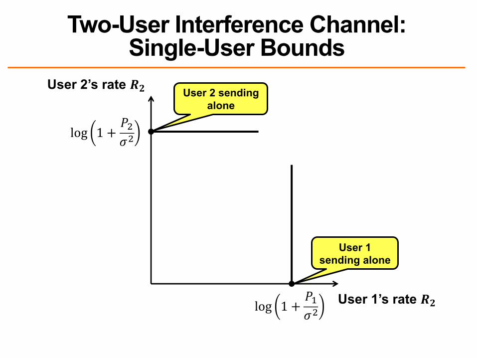
User 2’s rate !"
User 1’s rate !"
User 1 sending alone
log 1 + ()*+
User 2 sending alone
log 1 + (+*+

• Assumption: User 1’s data are completely independent from User 2’s data, and vice-versa
• Thought exercise: Point-to-point link sending with power !" + !$– Must outperform interfering link (otherwise interference helps)
• So therefore, %" + %$ < log 1 + +,-+./.
6
Interference Doesn’t Help

Two-User Interference Channel:Capacity Region
User 2’s rate !"
User 1’s rate !#log 1 + )*
+,
log 1 + ),+, -* + -, < log 1 + )* + ),+,
log 1 + )*), ++,

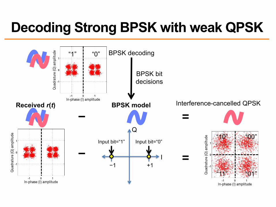
Successive Interference Cancellation (SIC)
• Receiver decodes information from both senders in three stages:
1. Decode data of user 1, treating signal from user 2 as noise
2. Reconstruct user 1’s signal (x’1[m]) from decoded data and subtract from
aggregate received signal y[m], cancelling it:
y’ [m] = y [m] − x’1[m]
= x2[m] + (x1[m] – x’1[m]) + w[m]
3. Decode user 2’s signal from y’[m]
“1” “0”
Decoding Strong BPSK with weak QPSK
I
Q
−1 +1
Input bit=“0”Input bit=“1”
BPSK model
“10” “00”
“01”“11”
=
=
Interference-cancelled QPSK
BPSK decoding
BPSK bitdecisions
−
−
Received r(t)

Power Difference Helps Superposition Coding
I
Q
−1 +1
Input bit=“0”Input bit=“1”
−

SIC: Choice of User OrderUser 2’s rate !"
User 1’s rate !#log 1 + )*
+,
log 1 + ),+,
-* + -, < log 1 + )* + ),+,log 1 + ),
)* ++,
log 1 + )*), + +,

• CDMA: Every user decoded treating the other users as noise– Achieves Point C
• But, User 1 starves
• CDMA power control: Reduce power of the strong user– Achieves Point D
12
Comparison with CDMA
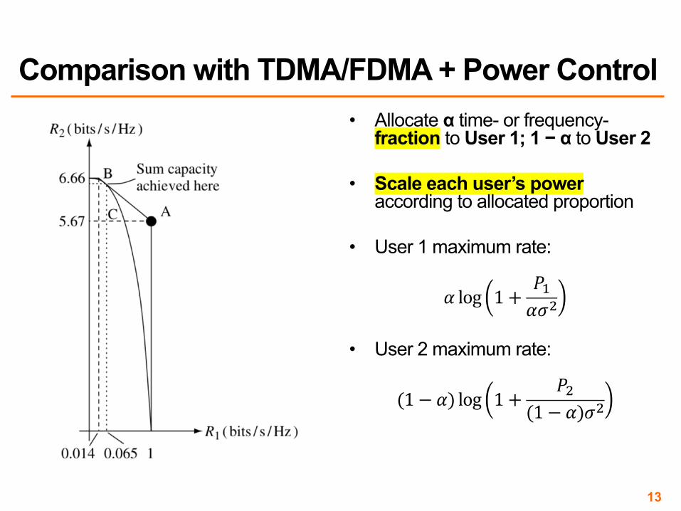
• Allocate α time- or frequency-fraction to User 1; 1 − α to User 2
• Scale each user’s poweraccording to allocated proportion
• User 1 maximum rate:
! log 1 + '(!)*
• User 2 maximum rate:
(1 − !) log 1 + '*(1 − !))*
13
Comparison with TDMA/FDMA + Power Control

• Allocate as follows: – α time- or frequency-fraction to User 1;
1 − α to User 2
• Tuning α, the users can achieve a point on the (optimal) A-B line
14
Comparison with TDMA/FDMA + Power Control
1. Interference Channel Capacity
2. MIMO Channel Capacity
3. Interference Alignment
Today
15

• Transmit three symbols per symbol time: ! =#$#%#&
• Represent the MIMO channel as ( = H!++
– H =ℎ$$ ℎ$% ℎ$$ℎ%$ ℎ%% ℎ$$ℎ&$ ℎ&% ℎ$$
is the MIMO channel matrix, + noise
Review: The MIMO Channel
- ≫ /
//2 antenna separation
2Send x1, x2, x3
Receive y1, y2, y3
3
//2 12
3
12
3
16

• MIMO link with nt transmit, nr receive antennas
• MIMO radio channel itself:
Recap: MIMO Radio Channel
x H +
w
ynt nr
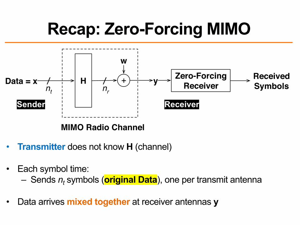
• Transmitter does not know H (channel)
• Each symbol time:– Sends nt symbols (original Data), one per transmit antenna
• Data arrives mixed together at receiver antennas y
Recap: Zero-Forcing MIMO
Data = x H +
w
ynt nr
Zero-Forcing Receiver
Received Symbols
MIMO Radio Channel
Sender Receiver

• Receiver knows H (channel)
• Each symbol time:– Receive nr mixed-up signals y– For each of the nt transmitted symbols:
• Zero-Forcing Receiver nulls all but that symbol
Recap: Zero-Forcing MIMO
Data = x H +
w
ynt nr
Zero-Forcing Receiver
Received Symbols
MIMO Radio Channel

1. Interference Channel Capacity
2. MIMO Channel Capacity– Vector Space Intuition – Eigenmode Forcing via Singular Value Decomposition
3. Interference Alignment
Today
20

• The story so far: Copy data into " ="$"%"&
each symbol time
– Looked at when this performed well, poorly• Answer: MIMO channel conditioning ß “Rich
multipath environment” around sender, receiver
* * *
• Today’s first topic: Is this the best bits/seconds/Hz possible?– What’s the capacity of a MIMO channel?
• Similar question: Shannon capacity of a single-input, single-output (SISO) channel
21
MIMO Channel Capacity: Motivation

• Suppose the transmitter knows H (channel)
• Zero-forcing receiver heard h1, h2, h3– Power loss at receiver (due to Proj⟘) for h3
• Idea: Use transmit antennas 2 and 3 to send the ideal direction– No longer simply one symbol, one transmit antenna
22
Where’s the Room for Improvement?
h2Send this instead of h3
h1
h3

• Sender precodes data !" into actual transmission in desired directions x
• Receiver processing changes accordingly
23
How Might We Control Directions?
x y+Precodex Receive
Processing y H
w
nt nr
MIMO Radio Channel
Sender Receiver
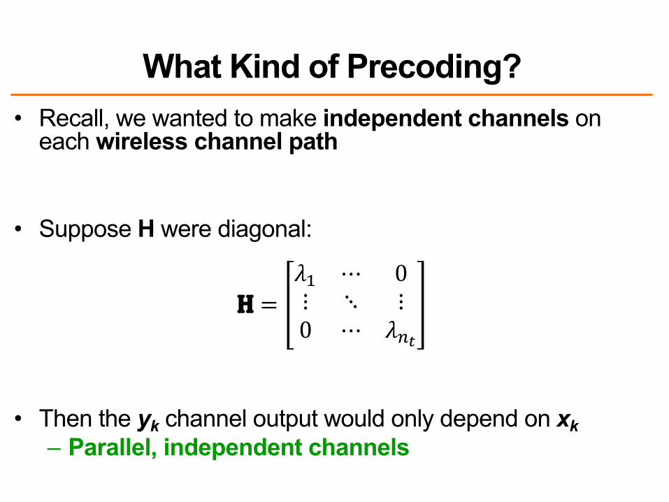
• Recall, we wanted to make independent channels on each wireless channel path
• Suppose H were diagonal:
H =#$ ⋯ 0⋮ ⋱ ⋮0 ⋯ #)*
• Then the yk channel output would only depend on xk– Parallel, independent channels
What Kind of Precoding?

1. Interference Channel Capacity
2. MIMO Channel Capacity– Vector Space Intuition – Eigenmode Transmission
3. Interference Alignment
Today
25

Singular Value Decomposition (SVD)• The insight lies in a special way of “factoring” matrix H
• Any matrix H has an SVD: H à UΛV*– Λ is a diagonal matrix (contains zeroes off-diagonal)– U and V are unitary (UU* = U*U = VV* = V*V = I)
H =
nt
nr Λ
nt
nrV*×
nt
ntU ×
nr
nr

• Λ matrix with the ! = min &', &) singular values *+,⋯ ,*-– One per significant radio channel path
• V* translates to the radio channel path coordinate systemwhere channels are decoupled
• U translates back, to antenna coordinate system (undoes the V* translation)
Interpreting the SVD Steps
H =
nt
nr Λ
nt
nrV*×
nt
ntU ×
nr
nr

x V* +
w
y
×
×
×
λ1
λ2
λm...
U
MIMO Radio Channel H
Leveraging the SVD in a Practical System• Alone, SVD does nothing (just analyzes what H does)
• Want to put data into the radio channel coordinate system
Want !" here à
Insight: VV* = I (Unitary property)

Leveraging the SVD in a Practical System– Sender precodes with V, receiver “post-codes” with U*
• V is unitary, so V*V = I (same for U)– So data sees independent channels
– This is called MIMO eigenmode transmission
x V*y
×
×
×
λ1
λ2
λm...
U
+
+
+
w1
w2
wm
x y
V U* y
MIMO Radio Channel H
Data x
Sender Receiver
No effect

• Performance model for the eigenmode transmitter/receiver
• All channels decoupled, transmit power Pkà SNR on i th channel: !"#"$
%$
30
A Model for Eigenmode Transmission
×
×
×
λ1
λ2
λm
...
+
+
+
w1
w2
wm
xm
x2
x1
ym
y2
y1
Sender Receiver

Performance: Uniform Power Division• At high SNR (the common case in wireless LANs), with total
transmit power P evenly divided over spatial paths
• Data rate = ∑"#$% log 1 + +,-.%/0
≈ 2 log(SNR)
* * *• How can we do better?
• Idea: Allocate different transmit powers 8" to different radio channel paths i
• Problem we’ve seen before in 463 in OFDM context
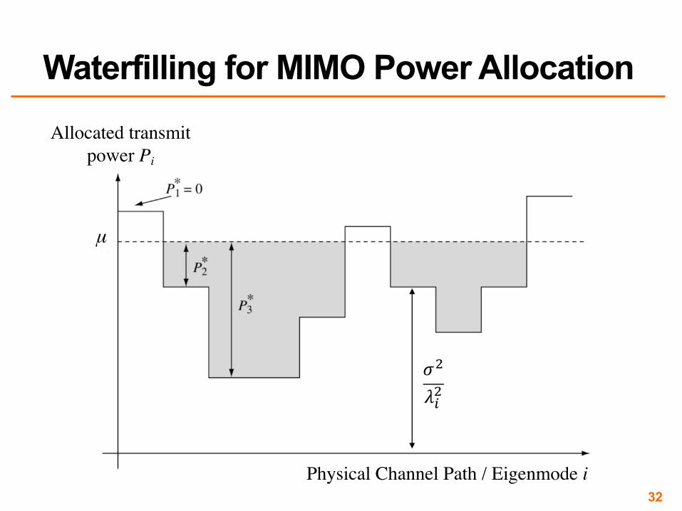
32
Waterfilling for MIMO Power Allocation
Physical Channel Path / Eigenmode i
μ
Allocated transmit power Pi
!"#$"
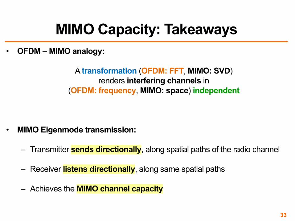
• OFDM – MIMO analogy:
A transformation (OFDM: FFT, MIMO: SVD) renders interfering channels in
(OFDM: frequency, MIMO: space) independent
• MIMO Eigenmode transmission:
– Transmitter sends directionally, along spatial paths of the radio channel
– Receiver listens directionally, along same spatial paths
– Achieves the MIMO channel capacity
33
MIMO Capacity: Takeaways
1. Interference Channel Capacity
2. MIMO Channel Capacity
3. Interference Alignment
Today
34

Interference Alignment (IA)• Number of concurrent MIMO streams a client can send is limited
by the number of antennas– Sending more streams results in interference between streams– Also limited by the amount of multipath in the environment
• New Idea: Use MIMO precoding techniques to align interference at receivers to advantage
• Requires APs cooperating via a wired backhaul– e.g.APs owned by one organization

MIMO channel representation• As before, model channel from one antenna i to another j as one
complex number ℎ"#
• Channel matrix H from a client to an AP is formed by [ℎ"#]
12h
11h
21h
22h
Client AP
10
1pH !!"
#$$%
&
21
0pH !!"
#$$%
&
p1
p2
!!"
#$$%
&=
2212
2111
hh
hhH
Figure 3: Two Packets on Uplink. The client transmits two packets,p1 and p2, from its two antennas. The packets arrive along the vectorsH[1 0]T and H[0 1]T , where H is the channel matrix and [.]T refers tothe transpose of a vector. To decode p1 and p2, the AP projects along thevectors orthogonal to H[0 1]T and H[1 0]T respectively.
802.11 channels. Similar to the current architecture, in IAC, adjacent
areas employ different 802.11 channels, but in contrast to the current
architecture, each of these areas is served by a set of APs on the same
channel, rather than a single AP. IAC allows this set of APs to serve
multiple clients at the same time despite interference. To do so, it
leverages the wired bandwidth to enable the APs to collaborate on
resolving interfering transmissions.
IAC has three components: 1) a physical layer that decodes con-
current packets across APs, 2) a MAC protocol that coordinates the
senders to transmit concurrently on the wireless medium, and 3) an
efficient mechanism to estimate channel parameters.
4 IAC’s Physical Layer
IAC modifies the physical layer to allow multiple client-AP pairs to
communicate concurrently on an 802.11 channel. IAC operates below
existing modulation and coding and is transparent to both.
For clarity, we present our ideas in the context of a 2-antenna per-
node system, and assume nodes know the channel estimates. Later,
we extend these ideas to any number of antennas and explain how we
measure channel functions. Our presentation focuses on scenarios
where interference from concurrent transmissions is much stronger
than noise and is the main factor affecting reception.
(a) Two concurrent packets on the uplink: Let us start with the
standard MIMO example in Fig. 3, where a single client transmits
two concurrent packets to an AP. Say that the client transmits p1
on the first antenna, and p2 on the second antenna. The channel
linearly combines the two packets (i.e., it linearly combines every two
digital samples of the packets). Hence, the 2-antenna AP receives the
following signals:
y1 = h11 p1 +h21 p2
y2 = h12 p1 +h22 p2,
where hi j is a complex number whose magnitude and angle refer to
the attenuation and the delay along the path from the ith antenna on
the client to the jth antenna on the AP, as shown in Fig. 3.
Since the nodes have two antennas, the transmitted and received
signals live in a 2-dimensional space. Thus, it is convenient to use 2-
dimensional vectors to represent the system [29]. This representation
will allow us to use simple figures to describe how a MIMO system
works. We can re-write the above equations as:!
y1
y2
"
= H
!
1
0
"
p1 +H
!
0
1
"
p2, (1)
where H is the 2×2 uplink channel matrix (i.e., the matrix of hi j’s).
Thus, the AP receives the sum of two vectors which are along the
directions H[1 0]T and H[0 1]T (where [.]T refers to the transpose
of a vector), as shown in Fig. 3.
1p
2p
3p
H11
H21
H12
H22
H11
1
0
! " # $ % &
H11
0
1
! " # $ % &
H21
1
0
! " # $ % &
H12
1
0
! " # $ % & H12
0
1
! " # $ % &
Clients APs
H22
H22
1
0
! " # $ % &
(a) Three Packets Without IAC.
Clients APs
111vH!
211vH!
321vH!
212vH!
322vH!
112vH!
2211vpvp!!
+
33vp!
11H
12H
22H
21H
Clients APs 322vH
(b) Three Packets With IAC.
Figure 4: Three Packets with/without IAC. In (a), the clients transmitthe packets without alignment. The packets combine at the APs alongthree different vectors and the APs cannot decode any packet. The sec-ond case shows how IAC delivers three packets on the uplink. Specifi-cally, two of the three packets are aligned at AP1, allowing AP1 to decodeone packet and send it to AP2 on the Ethernet. AP2 uses interference can-cellation to subtract the packet and decode the remaining two packets.
Assume the AP knows the channel matrix, H, (we will see how to
estimate it in §8). Decoding is easy; to decode p1, the AP needs to get
rid of the interference from p2, by projecting on a vector orthogonal to
H[0 1]T . To decode p2 it projects on a vector orthogonal to H[1 0]T .
We refer to the direction that a receiver projects on, to decode, as the
decoding vector.
(b) Three concurrent packets on the uplink: Consider what hap-
pens if another client concurrently transmits a packet, as shown in
Fig. 4a. Using the same derivation as above, AP1 receives:
!
y1
y2
"
= H11
!
1
0
"
p1 +H11
!
0
1
"
p2 +H21
!
1
0
"
p3,
where H11 and H21 are channel matrices from the first and second
clients to AP1. Said differently, AP1 receives the combination of three
packets p1, p2, and p3, along three vectors H11[1 0]T , H11[0 1]T and
H21[1 0]T , as shown in Fig. 4a. Since AP1 has only two antennas,
the received signal lives in a 2-dimensional space; hence AP1 cannot
decode three packets. Said differently, for any packet pi, the AP
cannot find a projection (decoding vector) that eliminates interference
caused by the other two packets. The second access point, AP2, is in
a similar state, it receives three packets along three vectors H12[1 0]T ,
H12[0 1]T and H22[1 0]T , and cannot decode for the same reason.
However, one advantage of MIMO is that a transmitter can control
the vectors along which its signal is received. For example, when a
transmitter transmits packet p1 on the first antenna, this is equivalent
to multiplying the samples in the packet by the unit vector [1 0]T
before transmission. As a result the received vector at the AP is
H[1 0]T p1, where H is the channel matrix from transmitter to receiver.
If the transmitter, instead, multiplies the packet p1 by a different
vector, e.g., v, the AP will receive the vector Hvp1. Thus, instead of
transmitting each packet on a single antenna, we multiply packet pi
by a vector vi (i.e., multiply all digital samples in the packet by the
vector) and transmit the two elements of the resulting 2-dimensional
161
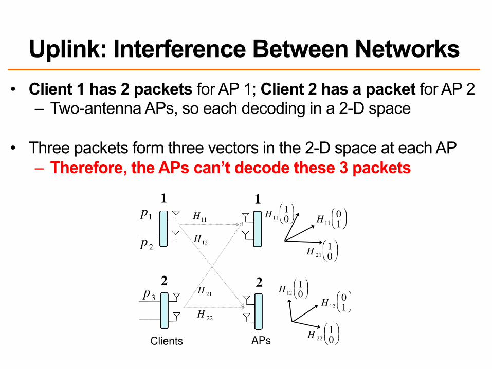
Uplink: Interference Between Networks• Client 1 has 2 packets for AP 1; Client 2 has a packet for AP 2
– Two-antenna APs, so each decoding in a 2-D space
• Three packets form three vectors in the 2-D space at each AP– Therefore, the APs can’t decode these 3 packets
12h
11h
21h
22h
Client AP
10
1pH
21
0pH
p1
p2
=
2212
2111
hh
hhH
Figure 3: Two Packets on Uplink. The client transmits two packets,p1 and p2, from its two antennas. The packets arrive along the vectorsH[1 0]T and H[0 1]T , where H is the channel matrix and [.]T refers tothe transpose of a vector. To decode p1 and p2, the AP projects along thevectors orthogonal to H[0 1]T and H[1 0]T respectively.
802.11 channels. Similar to the current architecture, in IAC, adjacent
areas employ different 802.11 channels, but in contrast to the current
architecture, each of these areas is served by a set of APs on the same
channel, rather than a single AP. IAC allows this set of APs to serve
multiple clients at the same time despite interference. To do so, it
leverages the wired bandwidth to enable the APs to collaborate on
resolving interfering transmissions.
IAC has three components: 1) a physical layer that decodes con-
current packets across APs, 2) a MAC protocol that coordinates the
senders to transmit concurrently on the wireless medium, and 3) an
efficient mechanism to estimate channel parameters.
4 IAC’s Physical Layer
IAC modifies the physical layer to allow multiple client-AP pairs to
communicate concurrently on an 802.11 channel. IAC operates below
existing modulation and coding and is transparent to both.
For clarity, we present our ideas in the context of a 2-antenna per-
node system, and assume nodes know the channel estimates. Later,
we extend these ideas to any number of antennas and explain how we
measure channel functions. Our presentation focuses on scenarios
where interference from concurrent transmissions is much stronger
than noise and is the main factor affecting reception.
(a) Two concurrent packets on the uplink: Let us start with the
standard MIMO example in Fig. 3, where a single client transmits
two concurrent packets to an AP. Say that the client transmits p1
on the first antenna, and p2 on the second antenna. The channel
linearly combines the two packets (i.e., it linearly combines every two
digital samples of the packets). Hence, the 2-antenna AP receives the
following signals:
y1 = h11 p1 +h21 p2
y2 = h12 p1 +h22 p2,
where hi j is a complex number whose magnitude and angle refer to
the attenuation and the delay along the path from the ith antenna on
the client to the jth antenna on the AP, as shown in Fig. 3.
Since the nodes have two antennas, the transmitted and received
signals live in a 2-dimensional space. Thus, it is convenient to use 2-
dimensional vectors to represent the system [29]. This representation
will allow us to use simple figures to describe how a MIMO system
works. We can re-write the above equations as:!
y1
y2
"
= H
!
1
0
"
p1 +H
!
0
1
"
p2, (1)
where H is the 2×2 uplink channel matrix (i.e., the matrix of hi j’s).
Thus, the AP receives the sum of two vectors which are along the
directions H[1 0]T and H[0 1]T (where [.]T refers to the transpose
of a vector), as shown in Fig. 3.
1p
2p
3p
H11
H21
H12
H22
H11
1
0
H11
0
1
H21
1
0
H12
1
0
H12
0
1
Clients APs
H22
H22
1
0
(a) Three Packets Without IAC.
Clients APs
111vH
211vH
321vH
212vH
322vH
112vH
2211vpvp
+
33vp
11H
12H
22H
21H
Clients APs 322vH
(b) Three Packets With IAC.
Figure 4: Three Packets with/without IAC. In (a), the clients transmitthe packets without alignment. The packets combine at the APs alongthree different vectors and the APs cannot decode any packet. The sec-ond case shows how IAC delivers three packets on the uplink. Specifi-cally, two of the three packets are aligned at AP1, allowing AP1 to decodeone packet and send it to AP2 on the Ethernet. AP2 uses interference can-cellation to subtract the packet and decode the remaining two packets.
Assume the AP knows the channel matrix, H, (we will see how to
estimate it in §8). Decoding is easy; to decode p1, the AP needs to get
rid of the interference from p2, by projecting on a vector orthogonal to
H[0 1]T . To decode p2 it projects on a vector orthogonal to H[1 0]T .
We refer to the direction that a receiver projects on, to decode, as the
decoding vector.
(b) Three concurrent packets on the uplink: Consider what hap-
pens if another client concurrently transmits a packet, as shown in
Fig. 4a. Using the same derivation as above, AP1 receives:
!
y1
y2
"
= H11
!
1
0
"
p1 +H11
!
0
1
"
p2 +H21
!
1
0
"
p3,
where H11 and H21 are channel matrices from the first and second
clients to AP1. Said differently, AP1 receives the combination of three
packets p1, p2, and p3, along three vectors H11[1 0]T , H11[0 1]T and
H21[1 0]T , as shown in Fig. 4a. Since AP1 has only two antennas,
the received signal lives in a 2-dimensional space; hence AP1 cannot
decode three packets. Said differently, for any packet pi, the AP
cannot find a projection (decoding vector) that eliminates interference
caused by the other two packets. The second access point, AP2, is in
a similar state, it receives three packets along three vectors H12[1 0]T ,
H12[0 1]T and H22[1 0]T , and cannot decode for the same reason.
However, one advantage of MIMO is that a transmitter can control
the vectors along which its signal is received. For example, when a
transmitter transmits packet p1 on the first antenna, this is equivalent
to multiplying the samples in the packet by the unit vector [1 0]T
before transmission. As a result the received vector at the AP is
H[1 0]T p1, where H is the channel matrix from transmitter to receiver.
If the transmitter, instead, multiplies the packet p1 by a different
vector, e.g., v, the AP will receive the vector Hvp1. Thus, instead of
transmitting each packet on a single antenna, we multiply packet pi
by a vector vi (i.e., multiply all digital samples in the packet by the
vector) and transmit the two elements of the resulting 2-dimensional
1
2
1
2
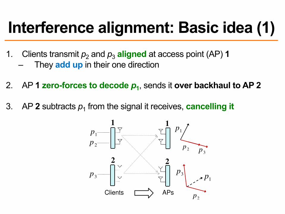
Interference alignment: Basic idea (1)1. Clients transmit p2 and p3 aligned at access point (AP) 1
– They add up in their one direction
2. AP 1 zero-forces to decode p1, sends it over backhaul to AP 2
3. AP 2 subtracts p1 from the signal it receives, cancelling it
Interference Alignment and Cancellation
Shyamnath Gollakota, Samuel David Perli and Dina KatabiMIT CSAIL
ABSTRACT
The throughput of existing MIMO LANs is limited by the number of
antennas on the AP. This paper shows how to overcome this limita-
tion. It presents interference alignment and cancellation (IAC), a new
approach for decoding concurrent sender-receiver pairs in MIMO
networks. IAC synthesizes two signal processing techniques, inter-
ference alignment and interference cancellation, showing that the
combination applies to scenarios where neither interference align-
ment nor cancellation applies alone. We show analytically that IAC
almost doubles the throughput of MIMO LANs. We also implement
IAC in GNU-Radio, and experimentally demonstrate that for 2x2
MIMO LANs, IAC increases the average throughput by 1.5x on the
downlink and 2x on the uplink.
Categories and Subject Descriptors C.2.2 [Computer Sys-
tems Organization]: Computer-Communications Networks
General Terms Algorithms, Design, Performance, Theory
Keywords Interference Alignment, Interference Cancellation
1 Introduction
Multi-input multi-output (MIMO) technology is emerging as the nat-
ural choice for future wireless LANs. The current design, however,
merely replaces a single-antenna channel between a sender-receiver
pair with a MIMO channel. The throughput of such a design is always
limited by the number of antennas per access point (AP) [5, 29]. Intu-
itively, if each node has two antennas, the client can simultaneously
transmit two packets to the AP. The AP receives a linear combination
of the two transmitted packets, on each antenna, as shown in Fig. 1.
Hence, the AP obtains two linear equations for two unknown packets,
allowing it to decode. Transmitting more concurrent packets than
the number of antennas on the AP simply increases interference and
prevents decoding. Thus, today the throughput of all practical MIMO
LANs is limited by the number of antennas per AP.
This paper introduces Interference Alignment and Cancellation
(IAC), a practical scheme to overcome the antennas-per-AP through-
put limit in MIMO LANs. IAC synthesizes two interference manage-
ment techniques: interference alignment and interference cancella-
tion, showing that the combination improves performance in scenarios
where neither interference alignment nor cancellation applies alone.
To get a feel for how IAC works, consider again a 2-antenna client
that uploads two concurrent packets to a 2-antenna AP. Say we have
Permission to make digital or hard copies of all or part of this work for personalor classroom use is granted without fee provided that copies are not made ordistributed for profit or commercial advantage and that copies bear this noticeand the full citation on the first page. To copy otherwise, to republish, to poston servers or to redistribute to lists, requires prior specific permission and/or afee.SIGCOMM’09, August 17–21, 2009, Barcelona, Spain.Copyright 2009 ACM 978-1-60558-594-9/09/08
2211111phphy +=
2221122phphy +=
12h
11h
h21
22h
Client AP
p1
p2
1y
2y
Figure 1: Throughput of current MIMO LANs is limited by the numberof antennas per AP. The hi j’s are known channel coefficients, and thepi’s are concurrent packets. The client transmits two concurrent packets.The AP receives a different linear combination of the transmitted packetson each antenna, which it solves to obtain the packets.
Clients APs
1p
2p
3p
1p3
p
1p
2p
3p
Clients APs2p
Figure 2: IAC Example. AP1 decodes packet p1 and sends the decodedpacket on the Ethernet to AP2 which then performs interference cancel-lation to subtract p1. As a result AP2 can decode p2 and p3.
a second 2x2 client-AP pair on the same wireless channel and within
interference range. Can the second client-AP pair concurrently upload
a third packet? In existing MIMO LANs, the three concurrent packets
interfere. As a result, each of the two APs gets two linear equations
with three unknown packets, and hence cannot decode.
In contrast, IAC allows these three concurrent packets to be de-
coded. To do so, IAC exploits two properties of MIMO LANs: 1)
MIMO transmitters can control the alignment of their signals at a
receiver, and 2) APs are typically connected to a backend Ethernet,
which they can use for coordination. Thus, in IAC, the two clients
encode their transmissions in a special way to align the second and
the third packets at AP1 but not at AP2, as shown in Fig. 2. As a
result, AP1 can treat the second and third packets as one unknown;
i.e., AP1 has the equivalent of two equations with two unknowns,
allowing it to decode the first packet, p1. AP1 then sends the decoded
packet on the Ethernet to AP2, which can now perform interference
cancellation to subtract the effect of the known packet. As a result,
AP2 is left with two linear equations over two unknown packets, p2
and p3, which it can decode. The system delivers three packets per
time unit. Hence, its throughput is not bounded by the number of
antennas per AP.
Note the synergy between interference alignment and interference
cancellation. Interference alignment aligns a subset of the packets at
the first AP, allowing it to locally decode one packet and hence boot-
strap the decoding process. Interference cancellation enables other
APs to use the decoded packet to cancel its interference, and hence
decode more packets. Neither interference alignment nor cancellation
would be sufficient on its own to decode the three packets in Fig. 2.
1
2
1
2

Interference alignment: Basic idea (2)
4. AP 2 uses zero-forcing receiver to decode p2, p3
5. AP 2 sends p2 to AP 1 (or onward on behalf of client 1)
Interference Alignment and Cancellation
Shyamnath Gollakota, Samuel David Perli and Dina KatabiMIT CSAIL
ABSTRACT
The throughput of existing MIMO LANs is limited by the number of
antennas on the AP. This paper shows how to overcome this limita-
tion. It presents interference alignment and cancellation (IAC), a new
approach for decoding concurrent sender-receiver pairs in MIMO
networks. IAC synthesizes two signal processing techniques, inter-
ference alignment and interference cancellation, showing that the
combination applies to scenarios where neither interference align-
ment nor cancellation applies alone. We show analytically that IAC
almost doubles the throughput of MIMO LANs. We also implement
IAC in GNU-Radio, and experimentally demonstrate that for 2x2
MIMO LANs, IAC increases the average throughput by 1.5x on the
downlink and 2x on the uplink.
Categories and Subject Descriptors C.2.2 [Computer Sys-
tems Organization]: Computer-Communications Networks
General Terms Algorithms, Design, Performance, Theory
Keywords Interference Alignment, Interference Cancellation
1 Introduction
Multi-input multi-output (MIMO) technology is emerging as the nat-
ural choice for future wireless LANs. The current design, however,
merely replaces a single-antenna channel between a sender-receiver
pair with a MIMO channel. The throughput of such a design is always
limited by the number of antennas per access point (AP) [5, 29]. Intu-
itively, if each node has two antennas, the client can simultaneously
transmit two packets to the AP. The AP receives a linear combination
of the two transmitted packets, on each antenna, as shown in Fig. 1.
Hence, the AP obtains two linear equations for two unknown packets,
allowing it to decode. Transmitting more concurrent packets than
the number of antennas on the AP simply increases interference and
prevents decoding. Thus, today the throughput of all practical MIMO
LANs is limited by the number of antennas per AP.
This paper introduces Interference Alignment and Cancellation
(IAC), a practical scheme to overcome the antennas-per-AP through-
put limit in MIMO LANs. IAC synthesizes two interference manage-
ment techniques: interference alignment and interference cancella-
tion, showing that the combination improves performance in scenarios
where neither interference alignment nor cancellation applies alone.
To get a feel for how IAC works, consider again a 2-antenna client
that uploads two concurrent packets to a 2-antenna AP. Say we have
Permission to make digital or hard copies of all or part of this work for personalor classroom use is granted without fee provided that copies are not made ordistributed for profit or commercial advantage and that copies bear this noticeand the full citation on the first page. To copy otherwise, to republish, to poston servers or to redistribute to lists, requires prior specific permission and/or afee.SIGCOMM’09, August 17–21, 2009, Barcelona, Spain.Copyright 2009 ACM 978-1-60558-594-9/09/08
2211111phphy +=
2221122phphy +=
12h
11h
h21
22h
Client AP
p1
p2
1y
2y
Figure 1: Throughput of current MIMO LANs is limited by the numberof antennas per AP. The hi j’s are known channel coefficients, and thepi’s are concurrent packets. The client transmits two concurrent packets.The AP receives a different linear combination of the transmitted packetson each antenna, which it solves to obtain the packets.
Clients APs
1p
2p
3p
1p3
p
1p
2p
3p
Clients APs2p
Figure 2: IAC Example. AP1 decodes packet p1 and sends the decodedpacket on the Ethernet to AP2 which then performs interference cancel-lation to subtract p1. As a result AP2 can decode p2 and p3.
a second 2x2 client-AP pair on the same wireless channel and within
interference range. Can the second client-AP pair concurrently upload
a third packet? In existing MIMO LANs, the three concurrent packets
interfere. As a result, each of the two APs gets two linear equations
with three unknown packets, and hence cannot decode.
In contrast, IAC allows these three concurrent packets to be de-
coded. To do so, IAC exploits two properties of MIMO LANs: 1)
MIMO transmitters can control the alignment of their signals at a
receiver, and 2) APs are typically connected to a backend Ethernet,
which they can use for coordination. Thus, in IAC, the two clients
encode their transmissions in a special way to align the second and
the third packets at AP1 but not at AP2, as shown in Fig. 2. As a
result, AP1 can treat the second and third packets as one unknown;
i.e., AP1 has the equivalent of two equations with two unknowns,
allowing it to decode the first packet, p1. AP1 then sends the decoded
packet on the Ethernet to AP2, which can now perform interference
cancellation to subtract the effect of the known packet. As a result,
AP2 is left with two linear equations over two unknown packets, p2
and p3, which it can decode. The system delivers three packets per
time unit. Hence, its throughput is not bounded by the number of
antennas per AP.
Note the synergy between interference alignment and interference
cancellation. Interference alignment aligns a subset of the packets at
the first AP, allowing it to locally decode one packet and hence boot-
strap the decoding process. Interference cancellation enables other
APs to use the decoded packet to cancel its interference, and hence
decode more packets. Neither interference alignment nor cancellation
would be sufficient on its own to decode the three packets in Fig. 2.
1
2
1
2

Uplink: Sketching a Practical Protocol
3. Client 2 chooses v3 so that H11v2 = H21v3– How does client 2 know H11 and H21?
• Client 1 can include in its packet header
12h
11h
21h
22h
Client AP
10
1pH
21
0pH
p1
p2
=
2212
2111
hh
hhH
Figure 3: Two Packets on Uplink. The client transmits two packets,p1 and p2, from its two antennas. The packets arrive along the vectorsH[1 0]T and H[0 1]T , where H is the channel matrix and [.]T refers tothe transpose of a vector. To decode p1 and p2, the AP projects along thevectors orthogonal to H[0 1]T and H[1 0]T respectively.
802.11 channels. Similar to the current architecture, in IAC, adjacent
areas employ different 802.11 channels, but in contrast to the current
architecture, each of these areas is served by a set of APs on the same
channel, rather than a single AP. IAC allows this set of APs to serve
multiple clients at the same time despite interference. To do so, it
leverages the wired bandwidth to enable the APs to collaborate on
resolving interfering transmissions.
IAC has three components: 1) a physical layer that decodes con-
current packets across APs, 2) a MAC protocol that coordinates the
senders to transmit concurrently on the wireless medium, and 3) an
efficient mechanism to estimate channel parameters.
4 IAC’s Physical Layer
IAC modifies the physical layer to allow multiple client-AP pairs to
communicate concurrently on an 802.11 channel. IAC operates below
existing modulation and coding and is transparent to both.
For clarity, we present our ideas in the context of a 2-antenna per-
node system, and assume nodes know the channel estimates. Later,
we extend these ideas to any number of antennas and explain how we
measure channel functions. Our presentation focuses on scenarios
where interference from concurrent transmissions is much stronger
than noise and is the main factor affecting reception.
(a) Two concurrent packets on the uplink: Let us start with the
standard MIMO example in Fig. 3, where a single client transmits
two concurrent packets to an AP. Say that the client transmits p1
on the first antenna, and p2 on the second antenna. The channel
linearly combines the two packets (i.e., it linearly combines every two
digital samples of the packets). Hence, the 2-antenna AP receives the
following signals:
y1 = h11 p1 +h21 p2
y2 = h12 p1 +h22 p2,
where hi j is a complex number whose magnitude and angle refer to
the attenuation and the delay along the path from the ith antenna on
the client to the jth antenna on the AP, as shown in Fig. 3.
Since the nodes have two antennas, the transmitted and received
signals live in a 2-dimensional space. Thus, it is convenient to use 2-
dimensional vectors to represent the system [29]. This representation
will allow us to use simple figures to describe how a MIMO system
works. We can re-write the above equations as:!
y1
y2
"
= H
!
1
0
"
p1 +H
!
0
1
"
p2, (1)
where H is the 2×2 uplink channel matrix (i.e., the matrix of hi j’s).
Thus, the AP receives the sum of two vectors which are along the
directions H[1 0]T and H[0 1]T (where [.]T refers to the transpose
of a vector), as shown in Fig. 3.
1p
2p
3p
H11
H21
H12
H22
H11
1
0
H11
0
1
H21
1
0
H12
1
0
H12
0
1
Clients APs
H22
H22
1
0
(a) Three Packets Without IAC.
Clients APs
111vH
211vH
321vH
212vH
322vH
112vH
2211vpvp
+
33vp
11H
12H
22H
21H
Clients APs 322vH
(b) Three Packets With IAC.
Figure 4: Three Packets with/without IAC. In (a), the clients transmitthe packets without alignment. The packets combine at the APs alongthree different vectors and the APs cannot decode any packet. The sec-ond case shows how IAC delivers three packets on the uplink. Specifi-cally, two of the three packets are aligned at AP1, allowing AP1 to decodeone packet and send it to AP2 on the Ethernet. AP2 uses interference can-cellation to subtract the packet and decode the remaining two packets.
Assume the AP knows the channel matrix, H, (we will see how to
estimate it in §8). Decoding is easy; to decode p1, the AP needs to get
rid of the interference from p2, by projecting on a vector orthogonal to
H[0 1]T . To decode p2 it projects on a vector orthogonal to H[1 0]T .
We refer to the direction that a receiver projects on, to decode, as the
decoding vector.
(b) Three concurrent packets on the uplink: Consider what hap-
pens if another client concurrently transmits a packet, as shown in
Fig. 4a. Using the same derivation as above, AP1 receives:
!
y1
y2
"
= H11
!
1
0
"
p1 +H11
!
0
1
"
p2 +H21
!
1
0
"
p3,
where H11 and H21 are channel matrices from the first and second
clients to AP1. Said differently, AP1 receives the combination of three
packets p1, p2, and p3, along three vectors H11[1 0]T , H11[0 1]T and
H21[1 0]T , as shown in Fig. 4a. Since AP1 has only two antennas,
the received signal lives in a 2-dimensional space; hence AP1 cannot
decode three packets. Said differently, for any packet pi, the AP
cannot find a projection (decoding vector) that eliminates interference
caused by the other two packets. The second access point, AP2, is in
a similar state, it receives three packets along three vectors H12[1 0]T ,
H12[0 1]T and H22[1 0]T , and cannot decode for the same reason.
However, one advantage of MIMO is that a transmitter can control
the vectors along which its signal is received. For example, when a
transmitter transmits packet p1 on the first antenna, this is equivalent
to multiplying the samples in the packet by the unit vector [1 0]T
before transmission. As a result the received vector at the AP is
H[1 0]T p1, where H is the channel matrix from transmitter to receiver.
If the transmitter, instead, multiplies the packet p1 by a different
vector, e.g., v, the AP will receive the vector Hvp1. Thus, instead of
transmitting each packet on a single antenna, we multiply packet pi
by a vector vi (i.e., multiply all digital samples in the packet by the
vector) and transmit the two elements of the resulting 2-dimensional
1
2
1
2
• Transmit precoding: client multiplies packet by vector v– Changes alignment at receiver
1. Client 1 picks randomprecoding vectors v1 and v2
2. Client 1 begins transmission

Uplink: Four Concurrent Packets?• All packets but one (p1) must align at AP 1, so AP 1 can decode
• Subtract p1 from the four packets at AP 2, leaving three packets
• AP 2 can only decode two packets at a time (2-d space)– Can’t decode p3 and p4 at AP 2: Can only decode p1 and p2
12h
11h
21h
22h
Client AP
10
1pH
21
0pH
p1
p2
=
2212
2111
hh
hhH
Figure 3: Two Packets on Uplink. The client transmits two packets,p1 and p2, from its two antennas. The packets arrive along the vectorsH[1 0]T and H[0 1]T , where H is the channel matrix and [.]T refers tothe transpose of a vector. To decode p1 and p2, the AP projects along thevectors orthogonal to H[0 1]T and H[1 0]T respectively.
802.11 channels. Similar to the current architecture, in IAC, adjacent
areas employ different 802.11 channels, but in contrast to the current
architecture, each of these areas is served by a set of APs on the same
channel, rather than a single AP. IAC allows this set of APs to serve
multiple clients at the same time despite interference. To do so, it
leverages the wired bandwidth to enable the APs to collaborate on
resolving interfering transmissions.
IAC has three components: 1) a physical layer that decodes con-
current packets across APs, 2) a MAC protocol that coordinates the
senders to transmit concurrently on the wireless medium, and 3) an
efficient mechanism to estimate channel parameters.
4 IAC’s Physical Layer
IAC modifies the physical layer to allow multiple client-AP pairs to
communicate concurrently on an 802.11 channel. IAC operates below
existing modulation and coding and is transparent to both.
For clarity, we present our ideas in the context of a 2-antenna per-
node system, and assume nodes know the channel estimates. Later,
we extend these ideas to any number of antennas and explain how we
measure channel functions. Our presentation focuses on scenarios
where interference from concurrent transmissions is much stronger
than noise and is the main factor affecting reception.
(a) Two concurrent packets on the uplink: Let us start with the
standard MIMO example in Fig. 3, where a single client transmits
two concurrent packets to an AP. Say that the client transmits p1
on the first antenna, and p2 on the second antenna. The channel
linearly combines the two packets (i.e., it linearly combines every two
digital samples of the packets). Hence, the 2-antenna AP receives the
following signals:
y1 = h11 p1 +h21 p2
y2 = h12 p1 +h22 p2,
where hi j is a complex number whose magnitude and angle refer to
the attenuation and the delay along the path from the ith antenna on
the client to the jth antenna on the AP, as shown in Fig. 3.
Since the nodes have two antennas, the transmitted and received
signals live in a 2-dimensional space. Thus, it is convenient to use 2-
dimensional vectors to represent the system [29]. This representation
will allow us to use simple figures to describe how a MIMO system
works. We can re-write the above equations as:!
y1
y2
"
= H
!
1
0
"
p1 +H
!
0
1
"
p2, (1)
where H is the 2×2 uplink channel matrix (i.e., the matrix of hi j’s).
Thus, the AP receives the sum of two vectors which are along the
directions H[1 0]T and H[0 1]T (where [.]T refers to the transpose
of a vector), as shown in Fig. 3.
1p
2p
3p
H11
H21
H12
H22
H11
1
0
H11
0
1
H21
1
0
H12
1
0
H12
0
1
Clients APs
H22
H22
1
0
(a) Three Packets Without IAC.
Clients APs
111vH
211vH
321vH
212vH
322vH
112vH
2211vpvp
+
33vp
11H
12H
22H
21H
Clients APs 322vH
(b) Three Packets With IAC.
Figure 4: Three Packets with/without IAC. In (a), the clients transmitthe packets without alignment. The packets combine at the APs alongthree different vectors and the APs cannot decode any packet. The sec-ond case shows how IAC delivers three packets on the uplink. Specifi-cally, two of the three packets are aligned at AP1, allowing AP1 to decodeone packet and send it to AP2 on the Ethernet. AP2 uses interference can-cellation to subtract the packet and decode the remaining two packets.
Assume the AP knows the channel matrix, H, (we will see how to
estimate it in §8). Decoding is easy; to decode p1, the AP needs to get
rid of the interference from p2, by projecting on a vector orthogonal to
H[0 1]T . To decode p2 it projects on a vector orthogonal to H[1 0]T .
We refer to the direction that a receiver projects on, to decode, as the
decoding vector.
(b) Three concurrent packets on the uplink: Consider what hap-
pens if another client concurrently transmits a packet, as shown in
Fig. 4a. Using the same derivation as above, AP1 receives:
!
y1
y2
"
= H11
!
1
0
"
p1 +H11
!
0
1
"
p2 +H21
!
1
0
"
p3,
where H11 and H21 are channel matrices from the first and second
clients to AP1. Said differently, AP1 receives the combination of three
packets p1, p2, and p3, along three vectors H11[1 0]T , H11[0 1]T and
H21[1 0]T , as shown in Fig. 4a. Since AP1 has only two antennas,
the received signal lives in a 2-dimensional space; hence AP1 cannot
decode three packets. Said differently, for any packet pi, the AP
cannot find a projection (decoding vector) that eliminates interference
caused by the other two packets. The second access point, AP2, is in
a similar state, it receives three packets along three vectors H12[1 0]T ,
H12[0 1]T and H22[1 0]T , and cannot decode for the same reason.
However, one advantage of MIMO is that a transmitter can control
the vectors along which its signal is received. For example, when a
transmitter transmits packet p1 on the first antenna, this is equivalent
to multiplying the samples in the packet by the unit vector [1 0]T
before transmission. As a result the received vector at the AP is
H[1 0]T p1, where H is the channel matrix from transmitter to receiver.
If the transmitter, instead, multiplies the packet p1 by a different
vector, e.g., v, the AP will receive the vector Hvp1. Thus, instead of
transmitting each packet on a single antenna, we multiply packet pi
by a vector vi (i.e., multiply all digital samples in the packet by the
vector) and transmit the two elements of the resulting 2-dimensional
€
H21 v 4
€
H22 v 4
1
2
€
p3 v 3 + p4
v 4

Downlink Interference Alignment• Clients can’t exchange frames over backhaul
• Instead, align neighboring APs’ interference at each client
11vp!
22vp!
111vH d !
221vH d !
331vH d !
222vH d !
332vH d !
112vH d !
Clients APs
33vp!
113vH d !
333vH d !
223vH d !
Figure 6: Three Packets on the Downlink. The APs deliver one packetto each client. To enable the client to decode its packet, all the undesiredpackets at the client must be aligned.
Clients AP
2p 1
p
3p
4p
2p
1p
3p
4p
2p
1p
3p
4p
Figure 7: Four Packets on Downlink. At the first client, packets p3 andp4 are aligned along one dimension, allowing p1 and p2 to lie in a twodimensional space and hence be decoded. Similarly, at the second client,packets p1 and p2 are aligned, allowing p3 and p4 to be decoded.
5 Beyond Two Antennas
The previous section focuses on 2-antenna systems, but for the gen-
eral case of M antennas per-node, what is the maximum number of
concurrent packets that can be delivered? Further, how many APs are
needed to support such a system?
Naively, it might seem that the number of concurrent packets is
constrained only by the number of APs. Specifically, it might seem
that one can align the received packets at every AP, allowing each of
them to decode at least one packet, and hence one can keep increasing
the number of concurrent packets by increasing the number of APs.
This is however misleading because aligning a signal at one receiver
limits the ability of the transmitter to freely align it at a second
receiver. In particular, every alignment imposes new constraints on
the encoding vectors at the transmitter. For a feasible solution, the
constraints should stay fewer than the free variables in an encoding
vector. Since the encoding vector has as many variables as there are
antennas on the node, the number of constraints cannot exceed the
number of antennas. Thus, using more APs is beneficial but only up
to a point, after which one needs to increase the number of antennas.
Below, we demonstrate that in IAC, the number of concurrent packets
can be almost twice the number of antennas, and that this gain is
achieved with a relatively small number of APs.
(a) Downlink. In [15], we prove the following:
Lemma 5.1 In a system with M antennas per node, the maximum
number of concurrent packets IAC can deliver on the downlink is
max{2M−2,⌊ 32 M⌋}. For M > 2, IAC achieves this with M−1 APs.
For M = 3, the above lemma tells us that we can achieve 4 concurrent
packets on the downlink. Fig. 7 shows the downlink case. We have
two APs and two clients. Each AP transmits two packets, one for
each client. Since the clients have three antennas, the signal is in a
3p
1p
2p
4p
p
2p
1p
6p
4p
5p
3p
5p
3p
2p
4p
6p
1p
2p
Clients AP
5p
6p
5p
3p
2
1p
4p
6p
Figure 8: Six Packets on Uplink. At AP1, all the packets other than p1
are aligned on a two dimensional plane, allowing p1 to be decoded. AtAP2, p2, p4 and p6 are aligned along, allowing p3 and p5 to be decoded.At AP3, we cancel p1, p3 and p5 leaving p2, p4 and p6 to lie along threedifferent dimensions and be decoded.
three dimensional space. Thus, if we align two packets along one
dimension, the other two packets are free of interference and can be
decoded, resulting in 4 concurrent packets.
The above procedure can be generalized to any number of antennas.
Specifically, if we have M−1 APs and two clients, a procedure that
makes each AP transmit a packet to each client can deliver a total of
2M−2 concurrent packets across the two clients. For a large M, this
almost doubles the throughput of current MIMO LANs.
(b) Uplink. In [15], we prove the following:
Lemma 5.2 For a M-antenna system, three or more APs, and at least
two clients, IAC can deliver 2M concurrent packets on the uplink.
For M = 3, the above lemma tells us that we can achieve 6 concur-
rent packets on the uplink. Fig. 8 shows three clients transmitting to
three APs. At the first AP, five out of six packets are aligned in the
same plane. This leaves one packet free of interference and hence
can be decoded. From the perspective of the second AP, one packet
is already decoded and hence can be eliminated from the received
signal. Out of the five packets left, the second AP needs to have three
packets aligned along one dimension and two free packets, allowing
it to decode two packets. Finally, from the perspective of the last AP,
three packets are already decoded and hence their interference can be
eliminated. This leaves the last AP with three unknown packets in a
three dimensional system and hence it can decode all of them.
Again, this procedure can be applied independent of the number of
antennas. Specifically, one needs to align 2M packets such that the
first AP can decode one packet, the second AP decodes M−1 packets
and the last AP decodes M packets.
6 Practical Issues
The practicality of IAC relies on being able to implement interfer-
ence alignment and interference cancellation. IAC uses only the
subtraction step of interference cancellation. Interference cancella-
tion typically involves two steps: first it decodes one of the concurrent
packets in the presence of interference and second it subtracts the
decoded packet from the rest to remove its contribution to interfer-
ence, allowing the decoding of more packets. IAC replaces the first
step with interference alignment to orthogonalize interference and
eliminate its impact as it decodes one of the concurrent packets. It
uses interference cancellation only to subtract the decoded packet.
The subtraction step of interference cancellation is widely studied
and has been shown to work in practical implementations [4, 14, 18].
163
p2, p3 aligned:
p1, p3 aligned:
p1, p2 aligned:

Thursday Topic:Ripple II: Faster Communication
through Physical Vibration
(Download & Pre-read paper!)
43


![MIMO Networks: the Effects of Interference · The MIMO capacity at high and low SNR for interference-limited scenarios is addressed in [16], [17]. A worst-case analysis for MIMO capacity](https://img.dokumen.tips/doc/110x75/5e6d1938c9ec0140a67912d9/mimo-networks-the-effects-of-interference-the-mimo-capacity-at-high-and-low-snr.jpg)