Embed Size (px)
Citation preview

C O N T E N T S
Milling Products
UNIVEX PREMIUM – 17mm End Mills and Face MIlls 90° 2
WPR-D – Helical Ball Nose Insert LC610Q 7
HSC FEEDTM – High Feed, Solid Carbide Roughing End Mills 10
AIR LINE® Solid Carbide – High Performance End Mills 14
HSC LINE® – Hard Milling Solid Carbide Ballnose End Mills 18
PL SERIES – Solid Carbide End Mills for Plastics 23
AL SERIES – Solid Carbide End Mills for Aluminum 28
Turning Products
POINT-BLANKTM Expansion – Additional Holder Program 33
ALUTEC LC600A – The New Revolution in Aluminum Turning 37
CASTEC® LC620H – Cast Iron Turning Grade 40
LC215H – High-Speed Machining Grade for Steel Turning 43
PENTATEC® – Multi-Functional Indexable Carbide Turning Tool 46
Reamers
SBR Reamers 54
FORMBORE
FORMBORE System Tools – A new development in technology and economy 63
Thread Rolling Products
Tangential Rolling Heads 66
Axial Rolling Heads 69
Tool Holding Products
BILZ THERMO-GRIPTM Shrink-Fit Units and Holders 88
NEW
NEW
NEW
NEW
NEW
NEW
NEW
NEW
NEW
NEW

2Www. LMTFETTE.com
ProductsLMT-Fette is pleased to announce UNIVEX PREMIUM. This new generation of 90º end millsand face mills is designed with ultra-high positive geometry and unequal pitched flutes for smooth performance, and a true 90º design for efficient and accurate corner milling.LMT-Fette’s new UNIVEX PREMIUM series of square shoulder mills achieve high feed rates,resulting in reduced cycle times. Unique ultra-durable nickel-plated bodies ensure long-termperformance. The UNIVEX PREMIUM end mills and face mills are designed with thru-the-toolcoolant supply improving chip evacuation and tool life. The UNIVEX PREMIUM end mills areavailable in Weldon shanks or straight shanks for precision mounting in end mill adapters.
The UNIVEX PREMIUM end mills and face mills feature precision indexable 17mm carbideinserts available with a variety of corner radii. A range of carbide substrates and coatings areavailable to meet your specific application needs, resulting in optimum cutting speeds andtool life, and excellent surface finishes.
Application AreaThe UNIVEX PREMIUM end mill and face mill cutters are designed to cover a wide range ofroughing and semi-finish milling applications. The UNIVEX PREMIUM cutters offer preciselocation of inserts to minimize witness lines when face milling. The milling cutters are avail-able in course and fine pitch for maximum feed rates in specific material groups. The insertsand body pocket design offer unmatched performance and smooth cutting action whenmilling in all steels, stainless, and non-ferrous materials. The new UNIVEX PREMIUM featuresa longer insert edge length for greater depths of cut, up to 0.6709. All UNIVEX PREMIUMmilling cutters are nickel-plated for long-term performance even when used in unfavorableconditions.
Materials The UNIVEX PREMIUM end mills and face mills are primarily designed for steel materialgroups. A broad selection of inserts, grades and chip breaking geometries make it an easychoice for machining materials from low carbon steel to mild steel and tool steels.
Advantages The new generation of UNIVEX PREMIUM end mills and face mills adds 17mm edge lengthinserts to our already successful UNIVEX 90º end mill and face mill program of 9mm and11mm. LMT-Fette offers the Total Tooling Solution with its complete line of 90º indexable endmills ranging from 1/29 to 1.59 diameters and face mills ranging from 29 to 49 diameters.
UNIVEX PREMIUM – 17mm End Mills and Face Mills 90°NEW

Dimensions (inches) No. Insert Torxd1 Cutter Body No. EDP doc (l2) l1 l3 d2 Teeth Insert Screw Driver
1.00 EMU90 A17-100WEI 12911 0.670 4.000 1.720 1.000 2
1.00 EMU90 A17-100SEI 12912 0.670 6.000 1.720 1.000 2 89973
1.00 EMU90 A17-100SEI 12913 0.670 10.000 1.720 1.000 2
1.25 EMU90 A17-125WFI 12914 0.670 4.000 1.720 1.250 2
1.25 EMU90 A17-125SFI 12915 0.670 6.000 1.720 1.250 2
1.25 EMU90 A17-125SFI 12916 0.670 10.000 1.720 1.250 2
1.25 EMU90 A17-125WFI 12917 0.670 4.000 1.720 1.250 3 ADKX 1705_ _ SR-TR 50259
1.25 EMU90 A17-125SCFI 12918 0.670 6.000 1.720 1.250 389974
1.50 EMU90 A17-150WGI 12919 0.670 4.500 1.720 1.500 3
1.50 EMU90 A17-150SGI 12920 0.670 6.000 1.720 1.500 3
1.50 EMU90 A17-150SGI 12921 0.670 10.000 1.720 1.500 3
1.50 EMU90A17.150WGIF 12922 0.670 4.500 1.720 1.500 4
1.50 EMU90 A17-150SGIF 12923 0.670 6.000 1.720 1.500 4
See pages 4 for insertsSee pages 4–6 for recommended cutting data and application information
UNIVEX PREMIUM – 17mm End Mills and Face Mills 90°
3www.LMTFETTE.com
908
l2
12–168
148
d2
l2
l1
d1
FMU90
Dimensions (inches) No. Insert Torxd1 Cutter Body No. EDP doc (l2) l1 d2 Teeth Insert Screw Driver
2.00 FMU90 A17-200AAI 12903 0.670 1.575 0.750 4
2.00 FMU90 A17-200AAIF 12904 0.670 1.575 0.750 5
2.50 FMU90 A17-250ABI 12905 0.670 1.575 1.000 5
2.50 FMU90 A17-250ABIF 12906 0.670 1.575 1.000 6ADKX 1705_ _ SR-TR 89974 50259
3.00 FMU90 A17-300ACI 12907 0.670 1.969 1.250 5
3.00 FMU90 A17-300ACIF 12908 0.670 1.969 1.250 8
4.00 FMU90 A17-400ADI 12909 0.670 1.960 1.500 6
4.00 FMU90 A17-400ADIF 12910 0.670 1.990 1.500 9
See pages 4 for insertsSee pages 4–6 for recommended cutting data and application information
908
l2
12–168
148
d2
l1
d1
l2
l3
EMU90

UNIVEX PREMIUM – 17mm End Mills and Face Mills 90°
4www.LMTFETTE.com
15°
sl
r
d1
d
Insert Description Dimensions (mm/inches) Insert Grade Ordering No. ForN = No. of ISO Code Cutter
Cutting Edges LMT Cat. No. l s d d1 r LC240T LC630T LC610T No.
ADKX 170508 SR-TR17.5 5.6 9.62 3.8 0.8
16024 16023 16022(.689) (.220) (.379) (.150) (0.031)
ADKX 170512 SR-TR17.5 5.6 9.62 3.8 1.2
16027 16026 16025(.689) (.220) (.379) (.150) (0.047) EMU90
ADKX 170516 SR-TR 17.5 5.6 9.62 3.8 1.6
16030 16029 16028FMU90
(.689) (.220) (.379) (.150) (0.062)
N = 2ADKX 170520 SR-TR
17.5 5.6 9.62 3.8 2.0 16033 16032 16031
(.689) (.220) (.379) (.150) (0.079)
Har
dm
ate-
rial
s
Gra
yc
ast
iro
n
Sta
inle
ss
Ste
el
P M K H
No
nfe
rro
us
mat
eria
ls
N
Hig
hte
mp
-er
ature
mat
eria
ls
S
Grade
05 15 25 35 4501 10 20 30 40 50
LC240THC-P40
HC-M40
HC-P20LC630T
HC-K15
HC-K10
HC-K10
HC-P10LC610T
HC-M10
ISO
Group of MaterialsRange of Applications
Grade Overview
Inserts

N
S
H
K
P
M
UNIVEX PREMIUM – 17mm End Mills and Face Mills 90°
5www.LMTFETTE.com
Cutting Data Recommendations
ISO Feed FPT / SFMCode Material Material Examples Rockwell C 0.003" - 0.006" 0.006" - 0.014" 0.014" - 0.020"
Plain Carbon Steel 1018, 1025 < 20 660 870 640
Free Machining Steel 1212, 12L13 < 20 660 870 640
Structural Alloy Steel 1040, 4130 < 30 590 870 640
Heat Treatment Steel, 4140, 6150 < 30 520 870 525
medium strength
Cast Steel 4340, 8740 < 30 520 750 525
Caste Hardening Steel 52100, 8620 < 30 520 750 525
Stainless Steel,ferritic 410, 430F, 440 < 30 520 750 525martensitic
Heat Treatment Steel,4140, 8740 28 - 44 390 575 460
high strength
Nitriding Steel A355 28 - 44 390 575 460
Tool Steel H13, D2 28 - 44 390 575 460
Stainless Steel, 304, 316 790 – 700
austenitic < 30
Maraging Steel 200 – 700
Grey Cast Iron A319, J431, No. 25B, No. 50B < 27 660 870 640
Alloyed Grey Cast Iron A434, A436-72 < 22 490 675 525
Nodular Cast Iron A536 (80-55-06), J434 < 34 490 610 460
Malleable Cast Iron A220, 50005, A47, 32510 < 29 520 610 460
Pure Metals, Pure Iron, Lead < 20 980 2030 –
soft
Aluminum Alloys,long chipping
6061, 7050 < 20 3280 2750 –
Aluminum Alloys,short chipping
A356, 4218 < 20 980 1150–
Copper Alloys,long chipping
C27200, B-148-52 < 20 820 2750 –
Copper Alloys,short chipping
< 20 820 1150 –
Magnesium Alloys B94, M11910 1310 1640 –
Thermoplastics PVC, Acrylic glass 820 1640 –
Duroplastics Durolite, Ampal 660 1640 –
Graphite 660 1640 –
Titanium Alloys,medium strength
F67, B265 < 29 260 – –
Titanium Alloys,high strength
Ti-6Al-4V 27 - 44 130 – –
Nickel Based Alloysmedium strength
20Cb3 < 29 200 280 230
Heat Resistant Nickel Based Alloys, Inconel 718 27 - 44 100 215 160high strength
Chilled Cast Iron Ampco 25 < 20 130 215 160
45 - 52 – 280 160
Hardened Steel 53 - 59 – 215 –
60 - 65 – 145 –

6www.LMTFETTE.com
UNIVEX PREMIUM – 17mm End Mills and Face Mills 90°
Ø 1.09 - 1.59 29 - 49
ISO-Code ADKX 1705_ _ ADKX 1705_ _
P .006 - .010 .008 - .012
M .006 .007
K .012 .014
N .014 .016
S .006 .006
Catalog No. EMU90 FMU90
Cutting Data Recommendations
ap max
d1
w1
Ramp Milling Using UNIVEX PREMIUM
W1 Max RampType Ø ISO Code Angle
1.00ADKX
4.0
EMU90 1.251705_ _
2.7
1.50 2.0
2.00 1.5
FMU902.50 ADKX 1.1
3.00 1705_ _ 0.8
4.00 0.6
Application Examples
Material: 4140 Pre-HardHardness: 27-32 HRC
LMT-Fette UNIVEX PREMIUM End MillCat. Desc. EMU90Ø 1.009 2 teethwith insertsInsert Grade LC630T
Cutting Datasfm 4 1,100rpm 4 2,130ipt 4 .0059
ipm 4 53woc 4 .0209
doc 4 .5009
Material: 4140 Pre-HardHardness: 27-32 HRC
LMT-Fette UNIVEX PREMIUM Face Milling CutterFMU90 A17-200Ø 2.009 5 teethwith insertsInsert Grade LC630T
Cutting Datasfm 4 825rpm 4 1,600ipt 4 .0069
ipm 4 40woc 4 1.4009
doc 4 .4009

7www.LMTFETTE.com
ProductsLMT-Fette is pleased to announce the helical-shaped, extremely free-cutting geometry of our new WPR-D Helical Ball Nose insert. The new insert provides long tool life and excellentsurface finishes when machining complex work pieces. The use of traditional inserts withstraight cutting edges typically results in unequal cutting forces, as well as increasedvibration, shorter tool life and slower feed rates. The WPR-D helical cutting edge results inincremental entry of the cutter and significantly reduces vibration for a soft, peeling cut. The WPR-D insert cutting edge is designed to always be under a load for increased stability and further reduced vibration.
Application AreaThe new WPR-D Helical Ball Nose inserts are designed to meet the demands of the growingsegment of high-speed machining in the die and mold market, on tool steels up to 60 Rc.
The inserts, with their free-cutting action, consistently proves to be a finishing tool of choice.Super-fine carbide substrate combined with a unique helical grind and PVD ALCrN coatingresult in a new standard for semi-finishing ball milling applications.
Materials WPR-D Helical Ball Nose inserts are designed for die and mold materials commonly used,such as tools steels P20, H13, A2, and D2. WPR-D helical inserts can also provide excellenttool life in softer alloy materials, less than 45 Rc. With its new enhanced coating, theLC610Q insert grade is suitable for either wet or dry milling applications.
AdvantagesThe primary advantage of LMT-Fette’s new WPR-D Helical Ball Nose insert is its ability to cutfreely, reduce vibration and extend tool life. The WPR-D insert geometry exhibits a helicalcutting action, providing soft, peeling cutting to the center of the insert, and in turn reducinghorsepower and increasing insert stability.
WPR-D – Helical Ball Nose Insert LC610QNEW

WPR-D – Helical Ball Nose Insert LC610Q
www.LMTFETTE.com
Har
dm
ate-
rial
s
Gra
yc
ast
iro
n
Sta
inle
ss
Ste
el
P M K H
No
nfe
rro
us
mat
eria
ls
N
Hig
hte
mp
-er
ature
mat
eria
ls
S
Grade
05 15 25 35 4501 10 20 30 40 50
LC610Q HC-K10
ISO
Group of MaterialsRange of Applications
Grade Overview
Insert Description Dimensions (inches) Insert Grade Ordering No. ForD = Helical ISO Code Cutter Body
Chipbreaker LMT Cat. No. d s LC610Q No.
WPR 0500-D 0.500 0.098 88218
WPR 0625-D 0.625 0.118 88219 EBG-R-T
WPR 0750-D 0.750 0.118 88220 EBG-R-N
WPR 1000-D 1.000 0.157 88221
WPR 12-D 12 2.5 88225
WPR 16-D 16 3.0 88226 EBG-R-T
WPR 20-D 20 3.0 88227 EBG-R-N
WPR 25-D 25 4.0 88228
Inserts
8

www.LMTFETTE.com9
WPR-D – Helical Ball Nose Insert LC610Q
N
S
H
K
P
M
ISO Feed FPT / SFMCode Material Material Examples Rockwell C .002" - .012" FPT
Plain Carbon steel 1018, 1025, < 20 1050 1300
Free Machining steel 1212, 12L13 < 20 1050 1300
Structural alloy steel 1040, 4130 < 30 1050 1300
Heat-treatment steel,medium strength
4140, 6150 < 30 1050 1300
Cast Steel 4340, 8740 < 30 850 980
Caste hardening steel 52100, 8680 < 30 850 980
Stainless steel,ferriticmartensitic
410, 430F, 440 < 30 850 980
Heat treatment steel,high strength
4140, 8740 28 - 44 680 790
Nitriding Steel A355 28 - 44 680 790
Tool Steel H13, D2 28 - 44 680 790
Stainless steel,austenitic
304, 316 < 30 – –
Maraging steel – –
Grey cast iron A319, J431No. 25B, No. 50B
< 27 1050 1300
Alloyed grey cast iron A434, A436-72 < 22 800 910
Nodular cast iron A536 (80-55-06), J434 < 34 725 820
Malleable cast ironA220, 50005A47,32510
< 29 725 820
Pure metals, soft Pure Iron, Lead < 20 2400 2760
Aluminum alloys,long chipping
6061, 7050 < 20 3120 3280
Aluminum alloys,short chipping
A356, 4218 < 20 1250 1570
Copper alloys,long chipping
C28000, B-148-52 < 20 3120 3280
Copper alloy,short chipping
< 20 1250 1570
Magnesium alloys B94, M11910 – 1570
Thermoplastics PVC, Acrylic glass – 1970
Duroplastics Durolite, Ampal – 1970
Graphite – 1970
Titanium alloys, medium strength
F67, B265 < 29 – –
Titanium alloys,high strength alloy
Ti-6Al-4V 27 - 44 – –
Nickel based alloys,medium strength
20Cb3 < 29 260 300
Heat resistant nickel basedalloys, high strength
Inconel 718 27 - 44 200 230
Chilled cast iron Ampco 25 < 20 200 230
45 - 52 260 300
Hardened steel 53 - 59 200 230
60 - 65 130 160
Cutting Data Recommendations

10www.LMTFETTE.com
ProductsLMT-Fette is pleased to announce the introduction of the first Solid Carbide High Feed End Mill. Called the HSC FEEDTM, these new cutters feature an exceptionally tough sub-micrograin substrate and LMT’s superior AL2 plus PVD Titanium Aluminum Nitridecoating. Combined, these two features offer the best combination of wear resistance and toughness.
Application AreaThe new HSC FEEDTM product is primarily designed for roughing and semi-finishing in the die and mold industry. In this application area, materials such as P20, H13, and S7 arecommonly a hardness up to nearly 60 Rc. However, the HSC FEEDTM also performs excep-tional in both carbon and alloy steels, cast iron, and stainless steel.
With its patented bottom radius design, the HSC FEEDTM can rough at chip loads 3–5 timeshigher than conventional solid carbide, ball nose end mills. This unique capability leads tometal removal rates significantly higher than conventional tools, and noticeable productivityimprovements.
HSC FEED’sTM unique, center-cutting design works exceptionally well in a wide range ofapplications, including 3D contouring, pocketing, helical interpolation, and slotting.
MaterialsAs stated above, the HSC FEEDTM was primarily designed for use in materials commonlyfound in the die and mold industry, including P20, H13, S7, and 400 series stainless steels.However, the design has also proved to be effective in virtually any steel application, as wellas cast iron. Because of the relatively heavy edge preparation on the HSC FEEDTM, it is notideally suitable for aluminum, graphite, titanium, or nickel-based alloys.
AdvantagesThe primary advantage of LMT-Fette’s new HSC FEEDTM product is in its ability to significantlyshorten roughing times in the machining of die and mold steels. With chip loads up to .0319
per tooth, and cutting speeds in excess of 650 sfm, it is common to run the HSC FEEDTM attable feeds exceeding 500 ipm.
Additionally, the unique geometry of the HSC FEEDTM leaves less stock in the corner ofpockets than a conventional ball nose end mill, thus reducing the number of tools necessaryto complete a mold.
Like the HSC Ball Nose End Mills, the HSC FEEDTM is also designed to cut material as hardas 60 Rc. The superior substrate and coating, combined with an exceptionally strong geom-etry can handle even the most demanding die and mold applications.
HSC FEEDTM – High Feed, Solid Carbide Roughing End MillsNEW

11www.LMTFETTE.com
HSC FEEDTM – High Feed, Solid Carbide Roughing End Mills
EDP Dimensions (mm/inches)
d1 Length No. I2 l1 l3 d3 d2 h6 Flutes *ap max Rtheo
INCH
0.187 Short 10388 0.075 2.000 0.660 0.156 0.250 2 0.009 0.019
0.187 Long 10389 0.075 3.000 1.500 0.156 0.250 2 0.009 0.019
0.250 Short 10390 0.104 2.500 0.770 0.208 0.250 2 0.013 0.025
0.250 Long 10391 0.104 3.250 1.750 0.208 0.250 2 0.013 0.025
0.312 Short 10392 0.120 2.500 0.940 0.260 0.312 2 0.016 0.031
0.312 Long 10393 0.120 3.500 2.100 0.260 0.312 2 0.016 0.031
0.375 Short 10394 0.136 2.500 1.060 0.312 0.375 2 0.019 0.038
0.375 Long 10395 0.136 4.000 2.250 0.312 0.375 2 0.019 0.038
0.500 Short 10396 0.167 3.500 1.420 0.417 0.500 2 0.025 0.050
0.500 Long 10397 0.167 4.500 2.500 0.417 0.500 2 0.025 0.050
METRIC
4.0 Short 55480 1.5 (0.059) 57 (2.244) 15 (0.591) 3.4 (0.134) 6 (0.236) 2 0.20 (0.008) 0.4 (0.016)
4.0 Long 55481 1.5 (0.059) 80 (3.150) 34 (1.339) 3.4 (0.134) 6 (0.236) 2 0.20 (0.009) 0.4 (0.016)
5.0 Short 55482 2.0 (0.079) 57 (2.244) 17.5 (0.689) 4.2 (0.165) 6 (0.236) 2 0.25 (0.010) 0.5 (0.020)
5.0 Long 55483 2.0 (0.079) 80 (3.150) 37 (1.457) 4.2 (0.165) 6 (0.236) 2 0.25 (0.010) 0.5 (0.020)
6.0 Short 55484 2.5 (0.098) 57 (2.244) 19 (0.748) 5.0 (0.197) 6 (0.236) 2 0.30 (0.012) 0.6 (0.024)
6.0 Long 55485 2.5 (0.098) 80 (3.150) 42 (1.654) 5.0 (0.197) 6 (0.236) 2 0.30 (0.012) 0.6 (0.024)
8.0 Short 55486 3.0 (0.118) 63 (2.480) 24 (0.945) 6.7 (0.264) 8 (0.315) 2 0.40 (0.016) 0.8 (0.031)
8.0 Long 55487 3.0 (0.118) 90 (3.543) 51 (2.008) 6.7 (0.264) 8 (0.315) 2 0.40 (0.016) 0.8 (0.031)
10.0 Short 55488 3.5 (0.138) 72 (2.835) 28.5 (1.122) 8.5 (0.335) 10 (0.394) 2 0.50 (0.020) 1.0 (0.039)
10.0 Long 55489 3.5 (0.138) 100 (3.937) 56.5 (2.224) 8.5 (0.335) 10 (0.394) 2 0.50 (0.020) 1.0 (0.039)
12.0 Short 55490 4.0 (0.157) 83 (3.268) 34 (1.339) 10.0 (0.394) 12 (0.472) 2 0.60 (0.024) 1.2 (0.047)
12.0 Long 55491 4.0 (0.157) 110 (4.331) 61 (2.402) 10.0 (0.394) 12 (0.472) 2 0.60 (0.024) 1.2 (0.047)
*denotes maximum axial depth of cut
Inch/Metric Solid Carbide, Center Cutting, High Speed Machining CNC
Style 1430C
Helix Angle 0°
Shank DIN 6535 HA
Coating PVD AL2 Plus
Grade LC620T
l1
d2 d1
l2l3
d3FETTE
Rtheo

www.LMTFETTE.com
HSC FEEDTM – High Feed, Solid Carbide Roughing End Mills
12
Application Examples
Face Milling
RampingRamp Angle = 1-2°
Pocketing
Circular interpolation 3D rough copy milling
Plunge MillingOpening cavity

13www.LMTFETTE.com
HSC FEEDTM – High Feed, Solid Carbide Roughing End Mills
K
M
P
ISO LC620T
Code Material Material Examples HRC Cutting Speed (sfm) Feed Per Tooth (fz)
Unalloyed Carbon SteelA36, 1005-1029,
16 - 30 800 - 1000 .0401213, 12L14
Alloyed Steel, 4140, 6150,< 30 800 - 990 .030
medium strength 5115, 8620
Heat Treatable Steel,4340 30 - 44 720 - 790 .030
high strength
Nitriding Steel H13 30 - 44 490 - 590 .030
Tool Steel A2, D2, P20 30 - 44 590 - 720 .030
Stainless Steel, 303, 304, 316, < 30 700 - 800 .030
austenitic Nitronic
Grey Cast Iron No. 30B< 30 750 - 820 .050
Alloyed Grey Cast Iron A436-725
Nodular Cast Iron 5005 < 23 550 - 590 .040
Alloyed Nodular Cast Iron 5005 < 16 450 - 590 .030
The cutting data indicated are starting values and must be adjusted to current machining conditions.
*We recommend reducing the feed per tooth value with the long length version by 30%.
Cutting Data Recommendations
Material: 4140 Pre-HardHardness: 27-32 HRC
LMT-Fette HSC FEEDTM MillCat. Desc. 1430 HSC FEEDTM MillØ 1/29 2 fluteCutting Material LC620T
Cutting Datasfm 4 1,100rpm 4 9,000ipt 4 .0309
ipm 4 540woc 4 .2009
doc 4 .0249
Application Examples
HSC FEED was used instead of a radius endmill for Z-level-roughing of a chissel die.
Feed rate could be doubled to vf (IPM) = 365, without changing speed of
vc (SFM) = 492 and tool life was 4 timeshigher.

14www.LMTFETTE.com
ProductsLMT-Fette has long been recognized as a premier supplier in the HSS and powdered metalend mill market. Now, LMT-Fette is pleased to announce the introduction of our first solidcarbide end mill product for the North American market, our new AIR LINE® Solid Carbideend mill. This unique end mill, some of which have “coolant-through” capability, is designedfor roughing and finishing in non-ferrous materials, as well as finishing in steel, stainlesssteel, and nickel-based alloys.
Application AreaThe AIR LINE® Solid Carbide end mill is designed primarily for use in roughing and finishingof non-ferrous alloys such as aluminum, magnesium, brass, etc. The AIR LINE® geometry,with its unique “stepped-relief,” 20° rake angle, and dead-sharp cutting edge, allows fortrouble free slotting and shouldering, even in softer aluminum alloys. This geometry combinedwith LMT-Fette’s new super-fine grain-grade substrate, provides unmatched, economicalremoval rates in all non-ferrous materials.
The AIR LINE® product also performs exceptionally in finishing applications on more difficultmaterials that benefit from a positive, up-sharp geometry. This geometry, when combinedwith our PVD TiAlN coating, also performs excellent in finishing of low-carbon steels,austenitic stainless steel, and nickel-based alloys.
The versatile design of the AIR LINE® Solid Carbide end mill performs even the most difficultend milling operation with ease.
MaterialsThe AIR LINE® Solid Carbide end mill is generally designed for materials commonly used inthe Aerospace industry, especially aluminum and magnesium alloys. However, the AIR LINE®
end mill has also shown exceptional versatility and excellent performance in brass, copper,and finishing of 300 series stainless steels and nickel-based alloys such as Inconel andHastelloy.
AdvantagesThe primary advantage of the AIR LINE® Solid Carbide end mill is its ability to run at 50%higher feed rates, leading to shorter machining times, specifically when combined with“coolant-through” capability. The slow-helix design of the tool, combined with the “stepped-relief,” leads to excellent edge strength, while maintaining a positive, up-sharp edge.Additionally, the AIR LINE’s® unique “coolant-though” capability leads to simplified chipremoval, thus improving process reliability.
AIR LINE® Solid Carbide – High Performance End Mills

15www.LMTFETTE.com
AIR LINE® Solid Carbide – High Performance End Mills
EDP Dimensions (inches) Thrud1 No. Helix l2 d2 l3 l1 Flutes Coolant
UNCOATED / LW630
0.250 53756 30° 0.625 0.250 0.813 2.500 2 Yes
0.375 53720 30° 0.875 0.375 1.250 3.000 2 Yes
0.500 53721 30° 1.125 0.500 1.500 3.500 3 Yes
0.625 53722 30° 1.250 0.625 1.750 4.000 3 Yes
0.750 53723 30° 1.500 0.750 2.125 4.000 3 Yes
1.000 53724 30° 2.000 1.000 2.750 4.000 3 Yes
0.250 53725 30° 0.625 0.250 0.813 2.500 2 No
0.375 53726 30° 0.875 0.375 1.250 3.000 2 No
0.500 53727 30° 1.125 0.500 1.500 3.500 3 No
0.625 53728 30° 1.250 0.625 1.750 4.000 3 No
0.750 53729 30° 1.500 0.750 2.125 4.000 3 No
1.000 53730 30° 2.000 1.000 2.750 4.000 3 No
COATED / LC630T
0.250 53731 30° 0.625 0.250 0.813 2.500 2 Yes
0.375 53732 30° 0.875 0.375 1.250 3.000 2 Yes
0.500 53733 30° 1.125 0.500 1.500 3.500 3 Yes
0.625 53734 30° 1.250 0.625 1.750 4.000 3 Yes
0.750 53735 30° 1.500 0.750 2.125 4.000 3 Yes
1.000 53736 30° 2.000 1.000 2.750 4.000 3 Yes
0.250 53737 30° 0.625 0.250 0.813 2.500 2 No
0.375 53738 30° 0.875 0.375 1.250 3.000 2 No
0.500 53739 30° 1.125 0.500 1.500 3.500 3 No
0.625 53740 30° 1.250 0.625 1.750 4.000 3 No
0.750 53741 30° 1.500 0.750 2.125 4.000 3 No
1.000 53742 30° 2.000 1.000 2.750 4.000 3 No
Solid Carbide, Super-Fine Grain Center Cutting End Mills
l1
d2d1
l2l3
l1
d2d1
l2l3
Style 1571
Primary Application Aluminum/Thermoplastics
Type SH
Standard DIN 6527 A
Helix Angle λ = 30°
Straight Shank Yes
Coating –
Cutting Materials LW630

AIR LINE® Solid Carbide – High Performance End Mills
16www.LMTFETTE.com
EDP Dimensions (mm/inches) Thrud1 No. Helix l2 d2 l3 l1 Flutes Coolant
UNCOATED / LW630
8 (0.315) 53743 30° 19 (0.748) 8 (0.315) 27 (1.063) 63 (2.480) 2 Yes
10 (0.394) 53744 30° 22 (0.866) 10 (0.394) 32 (1.260) 72 (2.835) 2 Yes
12 (0.472) 53745 30° 26 (1.023) 12 (0.472) 38 (1.496) 83 (3.267) 3 Yes
16 (0.630) 53746 30° 32 (1.260) 16 (0.630) 44 (1.732) 92 (3.622) 3 Yes
20 (0.787) 53747 30° 38 (1.496) 20 (0.787) 54 (2.126) 104 (4.095) 3 Yes
COATED / LC630T
8 (0.315) 54031 30° 19 (0.748) 8 (0.315) 27 (1.063) 63 (2.480) 2 Yes
10 (0.394) 53748 30° 22 (0.866) 10 (0.394) 32 (1.260) 72 (2.835) 2 Yes
12 (0.472) 53749 30° 26 (1.023) 12 (0.472) 38 (1.496) 83 (3.267) 3 Yes
16 (0.630) 53750 30° 32 (1.260) 16 (0.630) 44 (1.732) 92 (3.622) 3 Yes
20 (0.787) 53751 30° 38 (1.496) 20 (0.787) 54 (2.126) 104 (4.095) 3 Yes
Solid Carbide, Super-Fine Grain Center Cutting End Mills
Style 1571
Primary Application Aluminum/Thermoplastics
Type SH
Standard DIN 6527 A
Helix Angle λ = 30°
Straight Shank DIN 6535 HA
Coating –
Cutting Materials LW630
d2d1
l2l3
l1
d2d1
l2l3

17www.LMTFETTE.com
AIR LINE® Solid Carbide – High Performance End Mills
N
sfm Feed per Tooth
ISO Cutting Speed fz at Cutter Diameter d1
Code Material vc .250 - .394 .472 - .630 > .630
Aluminum2950 .004 .010 .010
Malleable Alloys
Aluminum2000 .004 .006 .001
Casting Alloys with < 12%
Aluminum820 .004 .006 .010
Casting Alloys with > 12%
Soft Plastic 1500 .006 .008 .012
Hard Plastic 1000 .005 .007 .010
Composites 1000 .002 .002 .003
Cutting Data Recommendations
Calculation Formulas
ap = .25 · d1
ae = .25 · d1
ap = .10 · d1
ae = .50 · d1
ap = .25 · d1 for Aluminum
ae = 1 · d1
ap = 2 · d1 for Plastics
Speed
n 5 vc · 1000 π · d1
f1 5 1.0 f1 5 0.9 f1 5 0.75
Feed Rate
vf 5 fz · z · n · f1
ae 5 Width of cut in inchap 5 Depth of cut in inchd1 5 Cutter diameter in inchf1 5 Correction factor vf
fz 5 Feed per tooth in inchn 5 rpm21
vc 5 Cutting speed in sfmvf 5 Feed rate in ipmz 5 No. of flutes
Feed Rate Correction Factor f1

18www.LMTFETTE.com
ProductsLMT-Fette’s new HSC LINE® of Solid Carbide End Mills are designed exclusively for thedemanding high-speed machining market. These new end mills feature a premium sub-micro-grain substrate combined with LMT-Fette’s superb AL2 Plus Titanium Aluminum Nitride PVDcoating, offering an excellent combination of performance and value.
The new product features standard, metric ballnose end mills from 0.4mm (.0169 ) to 12mm (.4729 ) in common sizes. In addition, LMT-Fette’s new HSC product also offers manyof these items in short, long, and extra long lengths for all of your toughest applications.
Application AreaThe new HSC LINE® of products is designed to meet the demands of today’s die and moldmarket. The line is for tool steels up to 60 Rc, austenitic stainless steels, and both grey andnodular iron. Additionally, with its TiAlN coating, this new product performs excellent ondemanding aerospace materials, Inconel, Hastelloy, etc. However, the primary applicationarea is in the machining of H13, P20, S7 and all of today’s common die and mold workpiecematerials.
With the high-speed machining market rapidly growing in the U.S. and Canada, ourcustomers continue to look for vendors that offer a comprehensive product offering, alongwith products that consistently perform in heat treated steels. Our new HSC LINE® exceeds all of these requirements, offering exceptional performance at a reasonable price.
MaterialsLike the TWINCUT Feed, the new HSC LINE® is generally designed for the materialscommonly used in the North American die and mold industry, such as H13, P20, etc. Thesematerials typically run in the 28–42 Rc range, with some of the hardened H13 running up into the low 50 Rc range. Additionally, many of the die and punch manufacturers in NorthAmerica are machining A2 and D2 Tool Steel at a hardness exceeding 60 Rc. The HSC LINE®
is also designed to perform well in these materials at significantly lower cutting speeds.
AdvantagesThe primary advantages of the LMT-Fette’s new HSC LINE® lie in the design of the product.This new product, unlike many of our competitors, is designed exclusively to meet thedemands of high-speed machining of hardened die and mold steels. The LC620T andLC630T are each optimized for their corresponding cutter family to offer the perfectcombination of heat and wear resistance, with excellent edge toughness.
The AL2 Plus coating is a unique PVD TiAlN coating designed to provide the perfectcombination of heat resistance and lubricity, adding to the versatility of these products.
Lastly, the geometry of the HSC LINE® is also designed for hardened materials, with rake angles and edge preparations capable of handling the demands put on a tool whenmachining materials up to 60 Rc.
HSC LINE® – Hard Milling Solid Carbide Ballnose End Mills

19www.LMTFETTE.com
HSC LINE® – Hard Milling Solid Carbide Ballnose End Mills
EDP Dimensions (mm/inches)
d1 No. l2 11 l3 d2 z r
SHORT
1 (0.039) 53987 1.5 (0.059) 38 (1.496) 2.7 (0.106) 3 (0.118) 2 0.5 (0.020)
2 (0.079) 53988 2 (0.079) 50 (1.969) 3.6 (0.142) 6 (0.236) 2 1 (0.039)
3 (0.118) 53989 3 (0.118) 50 (1.969) 5.5 (0.217) 6 (0.236) 2 1.5 (0.059)
4 (0.157) 53990 4 (0.157) 57 (2.244) 14.5 (0.571) 6 (0.236) 2 2 (0.079)
5 (0.157) 53991 5 (0.157) 57 (2.244) 14.5 (0.571) 6 (0.236) 2 2.5 (0.098)
6 (0.236) 53992 6 (0.236) 57 (2.244) 21 (0.827) 6 (0.236) 2 3 (0.118)
8 (0.315) 53993 8 (0.315) 63 (2.480) 27 (1.063) 8 (0.315) 2 4 (0.157)
10 (0.394) 53994 10 (0.394) 72 (2.830) 32 (1.260) 10 (0.394) 2 5 (0.197)
12 (0.472) 53995 12 (0.472) 83 (3.270) 38 (1.496) 12 (0.472) 2 6 (0.236)
LONG
2 (0.079) 53996 2 (0.079) 70 (2.756) 17 (0.669) 6 (0.236) 2 1 (0.039)
3 (0.118) 53997 3 (0.118) 70 (2.756) 18 (0.709) 6 (0.236) 2 1.5 (0.059)
4 (0.157) 53998 4 (0.157) 80 (3.150) 19 (0.748) 6 (0.236) 2 2 (0.079)
5 (0.197) 53999 5 (0.197) 80 (3.150) 44 (1.732) 6 (0.236) 2 2.5 (0.098)
6 (0.236) 54000 6 (0.236) 80 (3.150) 44 (1.732) 6 (0.236) 2 3 (0.118)
8 (0.315) 54001 8 (0.315) 90 (3.543) 54 (2.126) 6 (0.236) 2 4 (0.157)
10 (0.394) 54002 10 (0.394) 100 (3.937) 60 (2.362) 10 (0.394) 2 5 (0.197)
12 (0.472) 54003 12 (0.472) 110 (4.331) 65 (2.559) 12 (0.472) 2 6 (0.236)
EXTRA LONG
2 (0.079) 54004 2 (0.079) 120 (4.724) 17 (0.669) 6 (0.236) 2 1 (0.039)
3 (0.118) 54005 3 (0.118) 120 (4.724) 18 (0.709) 6 (0.236) 2 1.5 (0.059)
4 (0.157) 54006 4 (0.157) 160 (6.299) 19 (0.748) 6 (0.236) 2 2 (0.079)
5 (0.197) 54007 5 (0.197) 160 (6.299) 94 (3.700) 6 (0.236) 2 2.5 (0.098)
6 (0.236) 54008 6 (0.236) 160 (6.299) 94 (3.700) 6 (0.236) 2 3 (0.118)
8 (0.315) 54009 8 (0.315) 160 (6.299) 94 (3.700) 6 (0.236) 2 4 (0.157)
10 (0.394) 54010 10 (0.394) 160 (6.299) 94 (3.700) 10 (0.394) 2 5 (0.197)
12 (0.472) 54011 12 (0.472) 200 (7.874) 114 (4.490) 12 (0.472) 2 6 (0.236)
Metric Solid Carbide, Center Cutting, 2 Flute
Style 1412C
Helix Angle 20°
Shank Straight Shank DIN 6535 HA
Coating AL Plus (TiAlN) / LC620T
l3
d2
l2
r
d1
l1

20www.LMTFETTE.com
HSC LINE® – Hard Milling Solid Carbide Ballnose End Mills
EDP Dimensions (mm/inches)
d1 No. l2 11 l3 d2 z r
0.4 (0.0157) 54014 0.8 (0.032) 40 (1.575) 1.3 (0.051) 3 (0.118) 2 0.20 (0.0079)
0.5 (0.0197) 54015 1.0 (0.039) 40 (1.575) 1.5 (0.059) 3 (0.118) 2 0.25 (0.0098)
0.6 (0.0236) 54016 1.2 (0.047) 40 (1.575) 1.7 (0.067) 3 (0.118) 2 0.30 (0.0118)
0.8 (0.0315) 54017 1.6 (0.063) 40 (1.575) 2.1 (0.083) 3 (0.118) 2 0.40 (0.0157)
Metric Solid Carbide, Mini, Center Cutting, 2 Flute
Style 1419C
Helix Angle 30°
Shank Straight Shank DIN 6535 HA
Coating AL Plus (TiAlN) / LC630T
l2
l3
r
d1
d2
EDP Dimensions (mm/inches)
d1 No. l2 11 l3 l4 d2 d3 d4 r
4 (0.157) 54018 2.8 (0.110) 80 (3.150) 17.3 (0.681) 44 (1.732) 6 (0.236) 3.6 (0.142) 3.2 (0.126) 2 (0.079)
5 (0.197) 54019 3.6 (0.142) 80 (3.150) 21.1 (0.831) 44 (1.732) 6 (0.236) 4.5 (0.177) 4 (0.157) 2.5 (0.098)
6 (0.236) 54020 4.3 (0.169) 80 (3.150) 26.8 (1.055) 44 (1.732) 6 (0.236) 5.4 (0.213) 4.8 (0.189) 3 (0.118)
8 (0.315) 54021 5.7 (0.224) 90 (3.543) 29.6 (1.165) 54 (2.126) 8 (0.315) 7.3 (0.287) 6.8 (0.268) 4 (0.157)
10 (0.393) 54022 7.1 (0.280) 100 (3.937) 31.4 (1.236) 60 (2.362) 10 (0.394) 9.1 (0.358) 8.5 (0.335) 5 (0.197)
12 (0.472) 54023 8.5 (0.335) 110 (4.330) 36.4 (1.433) 65 (2.260) 12 (0.472) 10.9 (0.429) 10 (0.394) 6 (0.236)
Metric Solid Carbide, Center Cutting, 2 Flute
Style 1422C
Helix Angle 20°
Shank Straight Shank DIN 6535 HA
Coating AL Plus (TiAlN) / LC620T
d4
l1
l3
d3
r
d1
l4
d2
l2

21www.LMTFETTE.com
HSC LINE® – Hard Milling Solid Carbide Ballnose End Mills
H
S
K
M
P
LC620T/LC630TCutting
ISO Material Speed Feed per Tooth (fz)
Code Material Examples HRC (sfm) ≤ 1mm 1–2mm 2–4mm 4–6mm 6–10mm 12mm
Unalloyed Carbon SteelsA36, 1005–10291213, 12L14 < 16 1635 - 1965 .0008 .0012 .0016 .0032 .0040 .00521030–1055
Alloyed Steels 4140, 6150 < 30 1635 - 1965 .0008 .0012 .0016 .0032 .0040 .0052
Heat Treatable Steel, 4140, 4340 < 30 1475 .0004 .0005 .0008 .0020 .0032 .0040
medium strength
Heat Treatable Steel, 30-42 Rc 1150 .0004 .0008 .0016 .0024 .0032 .0044high strength
Cast Steel < 30 1475 .0003 .0004 .0006 .0020 .0032 .0040
Nitriding Steel H13 30-42 Rc 985 .0004 .0008 .0016 .0024 .0032 .0044
Tool Steel A2, S7, P20 30-42 Rc 820 .0004 .0008 .0016 .0024 .0032 .0044
Case Hardening Steel 8620, 52100 < 30 1310 .0003 .0004 .0006 .0020 .0032 .0040
Maraging Steel 785 - 985 .0004 .0012 .0020 .0028 .0036 .0044
Stainless Steel,austenitic
304, 316 < 30 785 - 985 .0004 .0012 .0020 .0028 .0036 .0044
Grey Cast Iron Class 30 < 16 1965 .0006 .0018 .0021 .0040 .0048 .0060
Alloyed Grey Cast Iron < 20 1635 .0006 .0010 .0022 .0030 .0038 .0048
Nodular Iron < 16 1150 .0006 .0010 .0022 .0030 .0038 .0048
Malleable Cast Iron < 20 1150 .0006 .0018 .0021 .0040 .0048 .0060
Titanium Alloys,Ti6Al4V < 30 600 .0004 .0008 .0016 .0028 .0036 .0044
medium strength
Titanium Alloys,27-44 Rc 400 .0004 .0006 .0014 .0026 .0040 .0048
high strength
Nickel-Based AlloysInconel 718, Hastelloy C
27-44 Rc 325 - 490 .0004 .0008 .0016 .0028 .0036 .0044
Chilled Cast Iron 655 .0004 .0006 .0008 .0016 .0026 .0032
45-52 Rc 1150 .0008 .0013 .0016 .0023 .0028 .0037
Hardened Steel 53-59 Rc 985 .0006 .0010 .0012 .0021 .0027 .0033
60-65 Rc 655 .0004 .0008 .0009 .0018 .0023 .0032
Cutting Data Recommendations
Application Examples
Machining of Forging Die
MaterialD2 Tool Steel54 HRC
Cutting Datadryvc (sfm) 4 927n (rpm) 4 15000fz 4 0.005vf (ipm) 4 79.6ae 4 0.008ap 4 0.008
ToolHSC LINE®
Solid Carbide End Mill#1412C, d1 4 .2369 (6.0mm)
Carbide GradeLC620TAL2 Plus (TiAlN)

22www.LMTFETTE.com
HSC LINE® – Hard Milling Solid Carbide Ballnose End Mills
Calculation of Cutting Data*
Ball Nose Solid Carbide End MillBall Nose End Mill with depth of cut
ap < 0.5 · d1
n =vc · 1000
[min–1]2 · π d1 · ap – ap2
ap = Depth of cutSd = Effective cut diameterd1 = Milling Cutter diameter
Sd = 2 · d1 · ap - ap2
.039 .079 .118 .157 .197 .236 .315 .472.394
30000
25000
20000
15000
RPM
(Rev
olua
tions
perm
inut
e)
10000
5000
0 1000 2000
Cutting Speed Vc (sfm)
r
3000 4000 5000
.
480
400
320
240
Feed
(inch
espe
rmin
ute)
160
80
0
rpm (revolutions per minute)
3
.012 fpt.
.008 fpt.
.004 fpt.
.002 fpt.
.001 fpt.
5000 10000 2000015000 25000 30000
Sd
ap
d1
d1
d4
Sd
ap
Milling Cutter with Corner RadiusCutter with depth of cutap < 0.5 · d4
n =vc · 1000
[min–1](d1 – d4 + 2 · d4 · ap – ap2) · π
d4 = 2 · Corner radius
Sd = d1 - d4 + 2 · d4 · ap - ap2
z = No. of teethfz = Feed/Toothf = Feed/Revolution
*Diagrams are validfor ap ≥ 0.5 · d1 respectively
ap ≥ 0.5 · d4 otherwisesee formula above
HSC End Mill Ball Nose
Rth = d1 – d12 – br2
2 4
ra = rth
8.7
br
d1
Rth
ϕ
r = Corner radius
d1 = Milling Cutter diameter
ϕ = Milling Cutter setting angle
100
80
60
40
20
0
Sur
face
roug
hnes
sR
th[µ
m]
Step-over br (inch)0.0 .020 .039 .059
d1 = .236 ϕ = 65°
HSC End Mill Ball Nose
Theoretical Surface Roughness Rth for High Speed Cutting

23www.LMTFETTE.com
ProductsLMT-Fette is pleased to announce the introduction of our new solid carbide PL SERIES EndMills for plastics. This line of tools is designed to cut both hard and soft plastics leavingsuperior surface finishes. The unique design allows for high chip loads and therefore highproduction rates, while leaving superior surface finishes.
Application AreaThe single edge PL SERIES End Mills are designed for production roughing and finishing of plastics. Target applications are sheet, stacked sheets, slab cutting, slotting, and nestedparts. The series is best in smaller diameter machining applications where good finish isimportant on the work piece. Machining plastic is easy when using the right tool with theright geometry, applied with the right methods. As a result of the PL SERIES geometry forplastic, there is no melting, chipping, or burrs, keeping productivity high.
And LMT-Fette’s super-fine grain grade substrate provides unmatched, economical removalrates on specific plastics (see materials).
MaterialsPL SERIES End Mills are designed specifically for the following plastics:
Hard Plastics: acrylic, nylon, PVC, polycarbonate and solid surface
Soft Plastics: HDPE, HIPS, UHMW, ABS, polycarbonate, PE, polystyrene, polypropylene,acetal, acrylic, PET and solid surface (Corian)
Softer plastics can be challenging materials to cut cleanly with a smooth surface finish. The PL SERIES will out-perform all multi-fluted tools when cutting these softer plastics.
AdvantagesThe primary advantage of the PL SERIES End Mills is their ability to take higher chip loads(faster feed rates) and deeper cuts with smaller diameters. This means you get more workdone with smaller diameter tools in less time. Therefore, if getting the job done fasterthrough less machining passes is important, the PL SERIES is the solution.
A key feature of the PL SERIES is their extremely sharp edge. The polished flutes andclearance create a razor-sharp edge essential for cutting plastics. The PL SERIES tools start out sharper and last longer in the cut.
Another key feature is getting the heat out in the chip, allowing the tool to run at coolertemperatures. Plastics are very sensitive to heat. Having only a single-flute, the PL SERIEStools cut 180° per revolution generating less heat. The geometry allows larger chips toevacuate through the open flute. Most multi-fluted tools can take large chips, but there is no place for them to go.
Lastly, the PL SERIES exhibits low cutting forces during the cut. The forces are half that of a 2-flute tool and a third of a 3-flute tool. This allows the tools to feed faster and deeper,leading to shorter machining times.
The tools have a 20°+ helix and a wide open flute design for chip flow, making themexcellent performers from low to extremely high (60,000+ RPM) spindle speed applications.
PL SERIES – Solid Carbide End Mills for Plastics

24www.LMTFETTE.com
EDP Dimensions (inches) No. ofd1 No. l2 d2 l1 Flutes Helix
UNCOATED / LW630
0.250 55787 1.250 0.250 3.000 2 22°
0.375 55789 1.500 0.375 4.000 2 22°
0.500 55790 1.250 0.500 4.000 2 22°
0.500 55791 1.750 0.500 4.000 2 22°
0.500 55792 2.125 0.500 4.000 2 22°
0.625 55793 1.750 0.625 5.000 2 22°
0.625 55794 2.250 0.625 5.000 2 22°
0.750 55795 2.500 0.750 5.000 2 22°
Solid Carbide, Double-Edge, Spiral Upcut O-Flute End Mills
Style 1491
Primary Application Acrylic and Hard Plastics
Helix Angle λ = 22°
Straight Shank Yes
Cutting Materials LW630
l1
d 2 d1
l2
PL SERIES – Solid Carbide End Mills for Plastics

25www.LMTFETTE.com
PL SERIES – Solid Carbide End Mills for Plastics
EDP Dimensions ( inches) No. ofd1 No. l2 d2 l1 Flutes Helix
UNCOATED / LW630
0.062 55814 0.250 0.125 2.000 1 21°
0.062 55815 0.250 0.250 2.000 1 21°
0.125 55816 0.250 0.125 2.000 1 21°
0.125 55817 0.250 0.250 2.000 1 21°
0.125 55818 0.500 0.125 2.000 1 21°
0.125 55819 0.500 0.250 2.000 1 21°
0.125 55820 0.500 0.250 2.000 1 21°
0.188 55821 0.375 0.188 2.000 1 21°
0.188 55822 0.375 0.250 2.000 1 21°
0.188 55842 0.625 0.188 2.000 1 21°
0.188 55843 0.625 0.250 2.000 1 21°
0.250 55844 0.375 0.250 2.000 1 21°
0.250 55845 0.750 0.250 2.500 1 21°
0.250 55846 0.750 0.250 2.500 1 21°
0.250 55847 1.250 0.250 3.000 1 21°
0.250 55848 1.500 0.250 3.000 1 21°
0.375 55849 0.625 0.375 2.500 1 21°
0.375 55850 0.750 0.375 3.000 1 21°
0.375 55851 1.125 0.375 3.000 1 21°
0.375 55852 1.625 0.375 3.500 1 21°
0.375 55853 1.625 0.375 3.500 1 21°
0.500 55854 1.625 0.500 3.500 1 21°
0.500 55855 1.625 0.500 3.500 1 21°
Solid Carbide, Single-Edge, Spiral Upcut O-Flute End Mills for Hard Plastics
Style 1485
Primary Application Hard Plastics
Helix Angle λ = 21°
Straight Shank Yes
Special Features Polished Flutes
Cutting Materials LW630
l1
d 2 d 1
l 2

26www.LMTFETTE.com
PL SERIES – Solid Carbide End Mills for Plastics
Solid Carbide, Single-Edge, Spiral Upcut O-Flute End Mills for Soft Plastics
EDP Dimensions (inches) No. ofd1 No. l2 d2 l1 Flutes Helix
UNCOATED / LW630
0.062 55856 0.250 0.125 2.000 1 21°
0.062 55857 0.250 0.250 2.000 1 21°
0.125 55858 0.250 0.125 2.000 1 21°
0.125 55859 0.250 0.250 2.000 1 21°
0.125 55860 0.500 0.125 2.000 1 21°
0.125 55861 0.500 0.250 2.000 1 21°
0.125 55862 0.500 0.250 2.000 1 21°
0.188 55863 0.375 0.188 2.000 1 21°
0.188 55864 0.375 0.250 2.000 1 21°
0.188 55865 0.625 0.188 2.000 1 21°
0.188 55866 0.625 0.250 2.000 1 21°
0.250 55867 0.375 0.250 2.000 1 21°
0.250 55868 0.750 0.250 2.500 1 21°
0.250 55869 0.750 0.250 2.500 1 21°
0.250 55870 1.250 0.250 3.000 1 21°
0.250 55871 1.500 0.250 3.000 1 21°
0.375 55872 0.625 0.375 2.500 1 21°
0.375 55873 0.750 0.375 3.000 1 21°
0.375 55874 1.125 0.375 3.000 1 21°
0.375 55875 1.625 0.375 3.500 1 21°
0.375 55876 1.625 0.375 3.500 1 21°
0.500 55877 1.625 0.500 3.500 1 21°
0.500 55878 1.625 0.500 3.500 1 21°
Style 1485S
Primary Application Soft Plastics
Helix Angle λ = 21°
Straight Shank Yes
Special Features Polished Flutes
Cutting Materials LW630
l1
d 2 d 1
l 2

27www.LMTFETTE.com
PL SERIES – Solid Carbide End Mills for Plastics
N
sfm Feed per Tooth*
ISO Cutting Speed fz at Cutter Diameter d1
Code Material Vc .062 - .188 .250 - .375 .500 - .625 .750
Soft Plastic 100 - 6000* .002 - .008 .008 - .012 .012 - .016 .016 - .018
Hard Plastic 100 - 6000* .002 - .008 .008 - .012 .012 - .016 .016 - .018
*Please note that the large variation in SFM is as a result of the wide range of tool diameters.
Cutting Data Recommendations
Plastic Material Cross-Reference
Material Tensile Strength
Group Material (N/mm2) Brand Name
Thermoplastics Acrylonitrile-butadiene-styrene 38 - 50 Lustran, Novodur, Terluran, Vestodur
Polypropylene 14 - 40 Hostalen, Novolen, Eltex, Vestolen
Polyvinyl chloride 8 - 20 Trovidur, Hostalit, Vestolit, Vinoflex, Vinnol
Polyethylene 22 - 40 Baylon, Sustylen, Hostalem, Lumpolen, Vestolen
Polycarbonate 65 - 75 Bayfol, Makrolon, Stapron, Lexan, Merlon
Polystyrene 30 - 60 Bucara, Langolen, Hostyren, Polystyrol
Acrylonitrile-styrene-acrylate 45 - 65 Polyman, Luran s
Polymethyl methacrylate 40 - 110 Acryl, Plexiglas, Resartglas, Pegalan
Polyoxymethylene 24 - 110 Aceton, Hostaform, Latan, Delrin, Ultraform
Polyamide (nylon) 50 - 120 Ultramid, Akromid, Polyloy, Nylon, Durethan
Polyethylene terephthalate 90 - 220 Hostaphan, Novatron
Polybutylene terephthalate 25 - 105 Enduran, Bitan, Celanex
Polyphenylene ether 55 - 68 Noryl, Vestoran
Polyaryletherketone 92 Tecapeek, Ultrax
Duroplastics Polyimide 75 -100 Sintimid, Kapton
Polyamide-imide 52 - 190 Torlon, Ensinger PAI
Polyetherimide 105 - 180 Ultern
Polymethacylimide 88 - 98 Rohacell
Phenol-formaldehyde (resin) 20 - 25 Delchi, Deltes, Resinol, Trolitan
Melamine-formaldehyde (resin) 15 - 300 Melmex, Urochem, Melopas, Duropal
Unsaturated polyester 25 - 40 Durolite, Ampal, Mitras, Tacon, Palatal
Epoxide 25 - 80 Epikote, Eposite, Epodur, Araldit
Composites Hard-paper honeycomb profiles Pertinax, Resocel

28www.LMTFETTE.com
28
ProductsLMT-Fette is pleased to announce the expansion of our high-performance aluminum machining tools with threenew product lines to solve tough machining problems.
• The AL-HPM-Line is a high-performance end mill line with corner radii to efficiently machine thin-walled partsfrom solids. These tools can take heavy chip loads while delivering ultra-smooth finishes.
• The AL-BALL-Line is a 3-flute ball nose tool line designed for efficient high feed profile machining inaluminum die/mold making applications.
• The AL-O-Line is a single-flute end mill line that cuts both hard and soft aluminum, with or without coolant,allowing very high chip-loads and deep cuts common in nesting and stacking of sheet parts.
Application AreaThe AL-HPM-Line is designed for the extremes of high speeds and feeds with low chatter, resulting in highlysmooth surface finishes. A common application is block aluminum machining through either high speedmachining (HSM) methods or high feed machining where the chip loads and depths of cut are higher. Cornerradii provide smooth bottom finishes. The special double-flute face helps to eject the chips at high feed rateseliminating chips from being re-cut or re-welded on to the finished parts.
The AL-BALL-Line is designed for high production profiling. The uniquely designed point has more flutes forroughing in deeper cuts. Near the point, the tool is effectively a single-flute, generating less heat, reducingburning or melting when finishing. This makes the AL-BALL a roughing and finishing tool in one, and can savesignificant time in die/mold prototyping.
The AL-O-Line is designed for production roughing and finishing of non-ferrous alloys such as aluminum,magnesium, brass, etc. The unique “O”-shaped flute geometry allows chips to flow through the center of thetool, ejecting out the other side. The flutes are polished, minimizing friction and build-up. The dead-sharp edgeis created with high rake and clearance combined with a low helix, resulting in lower cutting forces. The lowercutting forces allows for faster feeds and less deflection during the cut. This is a perfect tool when the diameter-to-length ratio is over 1:2, in applications such as sheet, stacked sheets, slab cutting, slotting, and nested.
MaterialsThe new LMT high-performance aluminum lines are designed specifically for machining aluminum alloys usedin aircraft industries such as 2024-O, 2024-T3, 6061-O, 6061-T6, 7075-O, 7075-T6.
Softer aluminums are one of the most challenging materials to cut. The AL-O-Line will out perform all multi-fluted tools cutting architectural aluminum alloys. While the tools will cut soft aluminum without coolant, use of coolant in softer materials will greatly extend tool life in architectural materials such as 3003-H and 5052-Hseries.
The new LMT high-performance aluminum end mills also excel in other non-ferrous materials such as brass,magnesium, and copper alloys.
AdvantagesThe primary advantage of the new LMT high-performance aluminum tools is their ability to take higher chiploads and deeper cuts with smaller diameters. The tools are very quiet in the cut, having a large sweet-spotrange. This means you get more work done with smaller diameter tools in less time. For example, the single-edge AL-O-Line tools allow faster feeds while taking deeper cuts, resulting in less machine passes and fasteroverall slotting operations.
A key feature of all of the new LMT high-performance aluminum tools is the ability to get the heat out in thechip, allowing the tools to run at a cooler temperature. Using a tool with the least number of flutes necessary toget the job done is normally the best solution. For example, a single-flute tool cutting 180° per revolutiongenerates less heat. By design, a single-flute tool allows larger chips to evacuate through the wide open flutearea. Most multi-fluted tools can take large chips but there is no place for the chips to go with small fluteopenings.
AL SERIES – Solid Carbide End Mills for Aluminum

29www.LMTFETTE.com
AL SERIES – Solid Carbide End Mills for Aluminum
EDP Dimensions (inches) No. ofd1 No. l2 d2 l3 l1 Flutes Helix
UNCOATED / LW630
0.062 55796 0.250 0.125 0.250 1.500 1 22°
0.094 55797 0.250 0.125 0.250 2.000 1 22°
0.125 55798 0.250 0.125 0.250 1.500 1 22°
0.125 55799 0.250 0.250 0.250 2.000 1 22°
0.125 55800 0.500 0.250 0.500 2.000 1 22°
0.188 55801 0.375 0.188 0.375 1.500 1 22°
0.188 55802 0.375 0.250 0.375 2.000 1 22°
0.188 55803 0.625 0.250 0.625 2.000 1 22°
0.250 55804 0.375 0.250 0.375 2.000 1 22°
0.250 55805 0.750 0.250 0.750 2.500 1 22°
0.250 55806 1.250 0.250 1.250 3.000 1 22°
0.312 55807 0.562 0.312 0.562 2.500 1 22°
0.312 55808 0.750 0.312 0.750 3.000 1 22°
0.375 55809 0.750 0.375 0.750 3.000 1 22°
0.375 55810 1.125 0.375 1.125 3.000 1 22°
0.375 55811 1.375 0.375 1.375 3.000 1 22°
0.500 55812 1.625 0.500 1.625 3.500 1 22°
0.500 55813 1.375 0.500 1.375 3.500 1 22°
Solid Carbide, Single-Edge, Spiral Upcut O-Flute End Mills for Aluminum
Style 1482
Primary Application Aluminum Sheets and Non-Ferrous Materials
Helix Angle λ = 22°
Straight Shank Yes
Cutting Materials LW630
l 1
d 2 d1
l 2

3030www.LMTFETTE.com
AL SERIES – Solid Carbide End Mills for Aluminum
l1
d
r
2 d1
l2
l3
Solid Carbide, High Performance End Mills for Aluminum
EDP Dimensions (inches) Corner No. ofd1 No. l2 d2 l3 l1 Radius Flutes Helix
UNCOATED / LW630
0.125 55879 0.250 0.125 0.500 2.000 0.002 2 40°
0.125 55880 0.250 0.250 0.250 2.000 0.005 2 40°
0.188 55881 0.375 0.188 0.875 2.000 0.002 2 40°
0.188 55882 0.375 0.188 0.875 2.000 0.008 2 40°
0.250 55883 0.375 0.250 1.125 2.500 0.002 2 40°
0.250 52917 0.375 0.250 1.125 2.500 0.020 2 40°
0.312 55884 0.500 0.312 1.125 2.500 0.020 2 40°
0.375 55885 0.500 0.375 1.125 2.500 0.002 2 40°
0.375 55886 0.500 0.375 1.125 2.500 0.020 2 40°
0.375 55887 0.750 0.375 – 3.000 0.020 2 40°
0.375 55888 0.500 0.375 2.125 4.000 0.020 2 40°
0.500 55889 0.750 0.500 1.500 3.000 0.002 2 40°
0.500 52918 0.625 0.500 1.375 3.000 0.020 2 40°
0.500 55891 0.750 0.500 1.500 3.000 0.020 2 40°
0.500 55892 0.625 0.500 2.125 4.000 0.020 2 40°
0.500 55900 0.625 0.500 3.125 5.000 0.020 2 40°
0.625 55893 0.750 0.625 1.625 3.500 0.002 2 40°
0.625 55006 0.750 0.625 1.625 3.500 0.020 2 40°
0.750 55894 1.250 0.750 2.000 4.000 0.002 2 40°
0.750 55895 1.000 0.750 1.625 4.000 0.020 2 40°
0.750 55896 1.000 0.750 2.500 6.000 0.020 2 40°
0.750 55897 1.250 0.750 2.000 4.000 0.020 2 40°
1.000 55898 1.500 1.000 3.125 5.000 0.002 2 40°
1.000 55899 1.500 1.000 3.125 5.000 0.020 2 40°
Style 1485
Primary Application Aluminum and Non-Ferrous Materials
Helix Angle λ = 40°
Straight Shank Yes
Cutting Materials LW630

31www.LMTFETTE.com
31
AL SERIES – Solid Carbide End Mills for Aluminum
l1
d2 d1
l2
l3r
Solid Carbide, High Performance Ball Nose End Mills for Aluminum
EDP Dimensions (inches) No. ofd1 No. l2 d2 l3 l1 Flutes Helix
UNCOATED / LW630
0.250 55903 0.375 0.250 0.375 2.500 3 45
0.250 55904 0.375 0.250 2.125 4.000 3 45
0.375 54211 0.500 0.375 0.375 3.000 3 45
0.375 55905 0.500 0.375 2.125 4.000 3 45
0.500 53577 0.625 0.500 0.500 3.000 3 45
0.500 55906 0.625 0.500 2.125 4.000 3 45
0.500 54795 0.625 0.500 4.125 6.000 3 45
0.750 55908 1.000 0.750 0.750 4.000 3 45
0.750 55909 1.000 0.750 4.125 6.000 3 45
Style 1482
Primary Application Aluminum and Non-Ferrous Materials
Helix Angle λ = 45°
Straight Shank Yes
Cutting Materials LW630

32www.LMTFETTE.com
AL SERIES – Solid Carbide End Mills for Aluminum
N
sfm Feed per Tooth*
ISO Cutting Speed fz at Cutter Diameter d1
Code Material vc .062 - .188 .250 - .375 .500 - .625 .750
Aluminum2950 .002 - .006 .002 - .010 .003 - .015 .005 - .020
Malleable Alloys
Aluminum2000 .002 - .006 .002 - .010 .003 - .015 .005 - .020
Casting Alloys with, <12% Si
Aluminum800 .002 - .006 .002 - .010 .003 - .015 .005 - .020
Casting Alloys with, >12% Si
*Please note that the recommended chip loads are based on 1 x D. For depths of 2 x D reduce the chip load by 25% and for 3 x D, pleasereduce your chip load by 50%.
Cutting Data Recommendations

33www.LMTFETTE.com
33
ProductsThe overwhelming response to LMT-Fette’s POINT-BLANKTM turning system has created the need to further expand the program. This program now includes popular Swiss-style OD turning holders and common boring bars.
This patented holder allows for the coolant to be put exactly where it is needed, on thecutting edge. This alone has a significant impact on chip control, tool life, and work piecesurface finish.
With our patented POINT-BLANKTM design, the coolant is directed to the cutting edge byway of our patented top plate or coolant nozzle design. There no longer is the worry ofcoolant lines being moved by stringy chips or high-coolant pressure. You will always havedirectional control of your coolant, and have it right where it is needed, on the cutting edge.
Application AreaThe POINT-BLANKTM tool holder is designed for use in all rough or finish turning applications.Where any standard turning holder is being used, the POINT-BLANKTM tool holder can beused. There is no longer the worry of where the coolant is hitting the insert. The versatiledesign of the POINT-BLANKTM tool holder allows maximum coolant volume and pressure tobe put directly on the cutting edge. With standard coolant pumps, increased coolant velocitycan be obtained to help with tool life and chip control.
AdvantagesThe primary advantage of POINT-BLANKTM tool holder concept is its ability to run LMT-Fette’sturning inserts at higher speeds and feeds because of the security and velocity of thecoolant flow. Additionally, all the dimensions are the same as standard tool holders so themachine programs do not have to be changed. The coolant-through capability allows forexcellent tool life, as well as tremendous chip evacuation. The increased coolant velocitykeeps the chips from adhering to the cutting edge and reduces the temperature at the cut-ting edge via increased lubricity, even while cutting at higher cutting speeds. Lastly, thePOINT-BLANKTM tool holder can be used with all standard LMT-Fette turning inserts, as well as any ANSI or ISO standard turning insert.
POINT-BLANKTM Expansion – Additional Holder ProgramNEW

34www.LMTFETTE.com
POINT-BLANKTM Expansion – Additional Holder Program
POINT-BLANKTM Direct Flow Boring Bars – For Inserts CCMT and CNMG
EDP Shank Min. Lock Clamp Seat Insert TorxDescription No. Insert Dia. Bore C F K° Seat Pin Clamp Screw Screw Screw Driver
Screw Lock Positive
A08M SCLCR-2 DFC 56590 CCMT 2(1.5)_ 0.500 0.625 6.000 0.312 8° 30861 36307
A12S SCLCR-3 DFC 55710 CCMT 3(2.5)_ 0.750 1.000 10.000 0.500 5°30864 36315
A16T SCLCR-3 DFC 55711 CCMT 3(2.5)_ 1.000 1.200 12.000 0.640 4°
Multiple Lock Negative Holders
A16T MCLNR-4 DFC 55709 CNMG 43_ 1.000 1.200 12.000 0.640 14° NL-44
A20U MCLNR-4 DFC 55741 CNMG 43_ 1.250 1.470 14.000 0.765 14°ICSN-433 CL-20 XNS-47 S-16
A24U MCLNR-4 DFC 56585 CNMG 43_ 1.500 1.760 14.000 0.890 12° NL-46
A32U MCLNR-4 DFC 56586 CNMG 43_ 2.000 2.400 16.000 1.281 12°
A32U MCLNR-6 DFC 56587 CNMG 64_ 2.000 2.400 16.000 1.281 12° ICSN-633 NL-68 CL-12 XNS-510 S-68
For Turning Inserts, please refer to our Turning Catalog, pages 18–47.
POINT-BLANKTM Direct Flow Screw Lock Positive Holders (Swiss Type) – For Inserts CCMT, DCMT, VCMT
Shank Shank Shape Insert NozzleDescription EDP No. Width Height C E F Insert Screw Screw
SCACR 08-3D DFC 55689 0.500 0.500 6.0 0.625 0.500
SCACR 10-3D DFC 55691 0.625 0.625 6.0 0.500 0.625 CCMT 3(2.5)_
SCACR 12-3D DFC 55693 0.750 0.750 6.0 0.625 1.000
SDJCR 08-3D DFC 55695 0.500 0.500 6.0 0.880 0.625
SDJCR 10-3D DFC 55697 0.625 0.625 6.0 0.880 0.750 DCMT 3(2.5)_
SDJCR 12-3D DFC 55699 0.750 0.750 6.0 0.880 1.000 55823 59778
SVJBR 08-3D DFC 55701 0.500 0.500 6.0 0.880 0.625
SVJBR 10-3D DFC 55703 0.625 0.625 6.0 0.880 0.750 VCMT 33_
SVJBR 12-3D DFC 55705 0.750 0.750 6.0 1.380 1.000
SVJCR 08-3D DFC 56439 0.500 0.500 6.0 0.880 0.625
SVJCR 10-3D DFC 56441 0.625 0.625 6.0 0.880 0.750 VCMT 33_
SVJCR 12-3D DFC 56443 0.750 0.750 6.0 1.380 1.000
For Turning Inserts, please refer to our Turning Catalog, pages 18–47.

35www.LMTFETTE.com
POINT-BLANKTM Expansion – Additional Holder Program
POINT-BLANKTM Direct Flow Negative Turning Holders
5∞
EC
FShank
Left hand view shown
EDP No. LockRight Left Shank Shank Shape Lock Pin Nozzle
Description Hand Hand Width Height C E F Insert Seat Pin Wrench Screw
MCLNR/L 12-4B DFC 53664 53662 0.75 0.75 4.50 1.25 1.00 CNM_ 43 ICSN 432 NL 46 54151 TS35.6-9M1
MCLNR/L 16-4D DFC 53665 53663 1.00 1.00 6.00 1.25 1.25 CNM_ 43 ICSN 432 NL 46 54151 TS35.6-9M1
MDJNR/L 12-3B DFC 53669 53666 0.75 0.75 4.50 1.25 1.00 DNM_ 33 IDSN 322 NL 34L 54152 TS35.6-9M1
MDJNR/L 12-4B DFC 53670 53667 0.75 0.75 4.50 1.25 1.00 DNM_ 43 IDSN 433 NL 46 54151 TS35.6-9M1
MDJNR/L 16-4D DFC 53671 53668 1.00 1.00 6.00 1.25 1.25 DNM_ 43 IDSN 433 NL 46 54151 TS35.6-9M1
MTJNR/L 12-3B DFC 53675 53672 0.75 0.75 4.50 1.25 1.00 TNM_ 33 ITSN 332 NL 34L 54152 TS35.6-9M1
MTJNR/L 16-3D DFC 53676 53673 1.00 1.00 6.00 1.25 1.25 TNM_ 33 ITSN 332 NL 34L 54152 TS35.6-9M1
MTJNR/L 16-4D DFC 53677 53674 1.00 1.00 6.00 1.25 1.25 TNM_ 43 ITSN 433 NL 46 54151 TS35.6-9M1
MVJNR/L 12-3B DFC 53681 53678 0.75 0.75 4.50 1.25 1.00 VNM_ 32 IVNS 322 NL 34L 54152 TS35.6-9M1
MVJNR/L 16-3D DFC 53682 53680 1.00 1.00 6.00 1.25 1.25 VNM_ 33 IVSN 322 NL 34L 54152 TS35.6-9M1
MWLNR/L 12-3B DFC 53686 53683 0.75 0.75 4.50 1.25 1.00 WNM_ 33 IWSN 322 NL 34L 54152 TS35.6-9M1
MWLNR/L 12-4B DFC 53687 53684 0.75 0.75 4.50 1.25 1.00 WNM_ 43 IWSN 432 NL 46 54151 TS35.6-9M1
MWLNR/L 16-3D DFC 55516 55517 1.00 1.00 6.00 1.25 1.25 WNM_ 33 IWSN 322 NL 34L 54152 TS35.6-9M1
MWLNR/L 16-4D DFC 53688 53685 1.00 1.00 6.00 1.25 1.25 WNM_ 43 IWSN 433 NL 46 54151 TS35.6-9M1
MCLNR/L 20-5D DFC 54995 55963 1.25 1.25 6.00 1.38 1.50 CNM_ 54 ICSN 533 NL 58 TS35.6-9M1
MCLNR/L 24-6D DFC 55008 55979 1.50 1.50 7.00 1.50 2.00 CNM_ 64 ICSN 633 NL 68 TS35.6-9M1
For turning inserts, please refer to our Turning Catalog, pages 18–47.
POINT-BLANKTM Direct Flow Positive Turning Holders
EDP No. Shim LockRight Left Shank Shank Shape Shim Filler Insert Nozzle
Description Hand Hand Width Height C E F Insert No. Screw Screw Screw
SCLCR/L 12-3B DFC 55494 10577 0.750 0.750 4.5 0.690 1.000 CCMT 3(2.5)_ 55799 55825 55823 TS35.6-9M1
SCLCR/L 16-3D DFC 10580 10581 1.000 1.000 6.0 0.690 1.250 CCMT 3(2.5)_ 55799 55825 55823 TS35.6-9M1
SDJCR/L 12-3B DFC 10584 10585 0.750 0.750 4.5 1.000 1.000 DCMT 3(2.5)_ 55826 55825 55823 TS35.6-9M1
SDJCR/L 16-3D DFC 10882 10883 1.000 1.000 6.0 1.000 1.000 DCMT 3(2.5)_ 55826 55825 55823 TS35.6-9M1
SVJCR/L 12-3B DFC 10886 10887 0.750 0.750 4.5 1.250 1.000 VCMT 33_ 55827 55825 55823 TS35.6-9M1
SVJCR/L 16-3D DFC 10890 10891 1.000 1.000 6.0 1.250 1.250 VCMT 33_ 55827 55825 55823 TS35.6-9M1

www.LMTFETTE.com36
POINT-BLANKTM Expansion – Additional Holder Program
Top Plate Coolant Nozzle
Clean Coolant Is Essential
• 200–300 PSI is recommended with standard machine pumps.
• A coolant volume of 8–10 gallons per minute is recommended. This is with a standard coolant pump without high pressure.
• The above calculations are estimated using the standardcoolant pumps on CNC lathes.
• Coolant must be kept clean. Coolant should be filtered to 5–20 microns if possible and at least 5–6% concentricity using a refractometer.
• Maximum recommended PSI — 1000 PSI
POINT-BLANKTM Coolant Set Up Instructions
• Insert 1/89 NPT fitting into toolholder bottom.
• Insert 89 length of Loc Line Hose (14 Segments) into the1/89 NPT fitting. Between 1/49 NPT fitting and hose, insertdouble socket fitting.
• Insert 1/49 NPT fitting into machine turret. If the turret hasan eye ball coolant nozzle, take out eye ball and remove1/49 NPT fitting. The end of the double socket can beinserted directly in turret and tightened down.
• If your machine turret has metric threads, screw in the 1/49
NPT fitting. It will tighten down without damaging the threadin the turret.
• Any other questions please contact your LMT sales repre-sentative.
EDP No.
Right Left ShapeHand Hand Description Insert
53690 53689 MCLNR/L 12-4B TP CNM_43
53692 53691 MCLNR/L 16-4B TP CNM_43
53694 53693 MDJNR/L 12-3B TP DNM_32
53696 53695 MDJNR/L 12-4B TP DNM_43
53698 53697 MDJNR/L 16-4D TP DNM_43
53701 53700 MTJNR/L 12-3B TP TNM_32
53703 53702 MTJNR/L 16-4B TP TNM_43
53705 53704 MVJNR/L 12-3B TP VNM_33
53707 53706 MVJNR/L 16-3B TP VNM_33
53709 53708 MWLNR/L 12-4B TP WNM_43
53711 53710 MWLNR/L 16-4B TP WNM_43
Loc Line Replacement Parts
EDP No. Description Qty.
54055 1/89 NPT Fitting 1
54057 89 Hose (14 segments) 1
54054 1/49 NPT Fitting 1
54056 Double Socket 1
54058 Wrench for Fittings 1
Recommended Loc Line ID: 1/49

www.LMTFETTE.com37
ProductsLMT-Fette is pleased to announce the introduction of a new diamond film coating, ALUTECLC600A. This new grade features a tungsten carbide substrate engineered for toughnessand wear resistance, and a PCD diamond film hard coating up to 10,000 Hardness Vickers.The new product will revolutionize rough and finish turning applications.
Application AreaWith an excellent balance of carbide substrate toughness, and highly wear resistant dia-mond coating, LC600A is excellent for turning of cast aluminum alloys. LC600A combinedwith our BAL (Boehlerit Aluminum) geometry provides optimum chip control and tool life inaluminum alloys with either low or high silicon content. The new PCD diamond-coating tech-nology of LC600A makes it possible to run at slower sfm ranges from 650 to extremely highranges over 9,800, providing the wide range of sfm needed when machining automotiveproducts such as cast aluminum wheels.
MaterialsAs stated above, LC600A’s primary application use is in machining of cast aluminum auto-motive products. Its performance is unmatched by the PCD coating technology. The nanocrystalline and microcrystalline layering process in LC600A inserts provides an excellent hard coat surface needed for tool life and improved finishes. Boehlerit offers the BAL chip breaker geometry in ISO style inserts more cutting edges than conventional brazedtipped cutting edge inserts.
AdvantagesCombining the toughness of tungsten carbide and the wear resistance of PCD, LMT-Fette’sLC600A insert grade is a new generation of diamond film coating produced to compete with conventional brazed PCD tipped inserts for machining of aluminum alloys. This newproduct offers five to ten times the tool life achieved by conventional tungsten carbideinserts. LMT-Fette offers its exclusive BAL geometry designed specifically for short and longchipping aluminum, materials providing optimum chip control compared to brazed PCD flattop style non-chip breaker inserts.
NEW ALUTEC LC600A – The New Revolution in Aluminum Turning

38www.LMTFETTE.com
ALUTEC LC600A – The New Revolution in Aluminum Turning
Indexable Inserts
EDP l d s d1 rNo. ANSI Designation ISO Designation edge length I/C thickness hole size radius
CCGT_ _ _ -BAL 13121 CCGT 431-BAL CCGT 120404-BAL 0.500 0.500 0.187 0.217 0.016
13122 CCGT 432-BAL CCGT 120408-BAL 0.500 0.500 0.187 0.217 0.031
DCGT _ _ _ -BAL 13123 DCGT 3 (2.5) 1-BAL DCGT 11T304-BAL 0.457 0.375 0.156 0.173 0.016
13124 DCGT 3 (2.5) 2-BAL DCGT 11T308-BAL 0.457 0.375 0.156 0.173 0.031
RCGT _ _ _ -BAL 13125 RCGT 0803-BAL RCGT 0803-BAL 0.315 0.125 0.134
13126 RCGT 1003-BAL RCGT 1003-BAL 0.394 0.125 0.157
TCGT _ _ _-BAL 13127 TCGT 2 (1.5) 1-BAL TCGT 110204-BAL 0.433 0.250 0.094 0.110 0.016
VCGT_ _ _ -BAL 13128 VCGT 331-BAL VCGT 160404-BAL 0.654 0.375 0.187 0.173 0.016
13129 VCGT 332-BAL VCGT 160408-BAL 0.654 0.375 0.187 0.173 0.031
13130 VCGT 333-BAL VCGT 160412-BAL 0.654 0.375 0.187 0.173 0.046
13131 VCGT 4 (3.5) (8)-BAL VCGT 220530-BAL 0.870 0.500 0.219 0.217 0.118
VPGT_ _ _-BAL 13132 VPGT 4 (3.5) (4)-BAL VCGT 220516-BAL 0.870 0.500 0.219 0.217 0.062
WCGT_ _ _-BAL 13133 WCGT 431-BAL WCGT 080404-BAL 0.339 0.500 0.187 0.217 0.016
13134 WCGT 432-BAL WCGT 080408-BAL 0.339 0.500 0.187 0.217 0.031

39www.LMTFETTE.com
ALUTEC LC600A – The New Revolution in Aluminum Turning
Har
dm
ater
ials
Gra
yc
ast
iro
n
Sta
inle
ss
Ste
el
P M K H
No
nfe
rro
us
mat
eria
ls
N
Hig
hte
mp
-er
ature
mat
eria
ls
S
Grade
05 15 25 35 4501 10 20 30 40 50
LC600A HC-K0 to K25
ISO
Group of MaterialsRange of Applications
Grade Overview
N
ISO FPR / SFMCode Material Material Examples Rockwell C .004 - .020
Pure Metals,
softPure Iron, Lead < 20
Aluminum Alloys,
long chipping6061, 7050 < 20 750 -10000
Aluminum Alloys,
short chippingA356, 4218 < 20
Cutting Data Recommendations
Application Examples
Application: Inside ProfilingWorkpiece: 140 diameter RimMaterial: 6061-T6 Alum.Insert / Grade: VCGT 160412-BAL LC600ACutting Data: 750 - 9500 SFM
.0800 - .1600 DOC
.0100 - .0200 FPRCoolant: Minimum quantity lubricant
2500
2000
1500
1000
500
100
0
Result: A 24 fold increase in toollife
Application: Inside ProfilingWorkpiece: 160 x 6.50 diameter RimMaterial: 6061-T6 Alum.Insert / Grade: VCGT 160412-BAL LC600ACutting Data: 750 - 9500 SFM
.0800 - .1600 DOC
.0100 - .0200 FPRCoolant: Full flood coolant
600
500
400
300
200
100
0
Result: A 6 fold increase in toollife

ProductsLMT-Fette is pleased to introduce our new CASTEC® LC620H turning grade for ductile irons,malleable irons, and grey iron materials. Cast iron materials vary greatly in the compositionof the alloy. They also vary in the cool down times, have different fluctuating physicalproperties, and are produced by various casting methods. These materials are bestmachined by means of indexable inserts made from carbide. LC620H provides K20substrate carbide that is gradient-sintered to provide excellent edge toughness. LC620H is amulti-layer MT-coated grade featuring TiN, TiCN, and Al2O3 for excellent heat- andwear-resistance.
Application AreaCASTEC® LC620H turning grade is designed with a special, ceramic layered coating and ishighly resistant to crater wear in abrasive cast iron materials. The main problem with castiron is the heat that is generated during machining, not chip breaking. This grade reducesthe friction during machining so that less heat is generated, making dry machining possiblefrom an economic point of view.
Materials In the development of the CASTEC® LC620H, the focus was on a tough, carbide substratecovered with a fine, extremely wear-resistant MT-CVD layer coating. CASTEC® LC620Hturning grade is a universal turning grade for all cast iron materials such as ductile,malleable, and grey iron.
AdvantagesThe primary advantage of the new LC620H is its ability to handle a wide range of cast ironmaterials. In difficult turning operations such as high abrasive materials, LC620H providesthe ultimate crater wear-resistance and tool life. The new CASTEC® LC620H adds moreflexibility with a wide range of ISO/ANSI indexable inserts. They allow more productivity by increased performance, tool life and reduced overall production costs.
CASTEC® LC620H – Cast Iron Turning Grade
40www.LMTFETTE.com
NEW

41www.LMTFETTE.com
Indexable Inserts
EDP l d s d1 rNo. ANSI Designation ISO Designation edge length I/C thickness hole size radius
13135 CCMT 3 (2.5) 1-BSM CCMT 09T304-BSM 0.382 0.375 0.156 0.173 0.016
13136 CCMT3 (2.5) 2-BSM CCMT 09T308-BSM 0.382 0.375 0.156 0.173 0.031
13137 CCMT 432-BSM CCMT 120408-BSM 0.508 0.500 0.187 0.217 0.031
13138 CCMT 433-BSM CCMT 120412-BSM 0.508 0.500 0.187 0.217 0.047
13139 CNMA 432 CNMA 120408 0.508 0.500 0.187 0.217 0.031
13140 CNMA 433 CNMA 120412 0.508 0.500 0.187 0.217 0.047
13141 CNMA 434 CNMA 120416 0.508 0.500 0.187 0.217 0.062
13142 CNMG 432-BM CNMG 120408-BM 0.508 0.500 0.187 0.217 0.031
13143 CNMG 433-BM CNMG 120412-BM 0.508 0.500 0.187 0.217 0.047
13144 CNMG 432-BMR CNMG 120408-BMR 0.508 0.500 0.187 0.217 0.031
13145 CNMG 433-BMR CNMG 120412-BMR 0.508 0.500 0.187 0.217 0.047
13146 CNMG 434-BMR CNMG 120416-BMR 0.508 0.500 0.187 0.217 0.062
13147 CNMG 543-BMR CNMG 160612-BMR 0.508 0.500 0.187 0.217 0.047
13148 CNMG 544-BMR CNMG 160616-BMR 0.508 0.500 0.187 0.217 0.062
13149 DCMT 3 (2.5) 1-BSM DCMT 11T304-BSM 0.457 0.375 0.156 0.173 0.016
13150 DCMT 3 (2.5) 2-BSM DCMT 11T308-BSM 0.457 0.375 0.156 0.173 0.031
13151 DNMA 432 DNMA 150408 0.610 0.500 0.187 0.203 0.031
13152 DNMA 433 DNMA 150412 0.610 0.500 0.187 0.203 0.047
13153 DNMA 442 DNMA 150608 0.610 0.500 0.250 0.203 0.031
13154 DNMA 443 DNMA 150612 0.610 0.500 0.250 0.203 0.047
13155 DNMG 432-BMR DNMG 150408-BMR 0.610 0.500 0.187 0.203 0.031
13156 DNMG 433-BMR DNMG 150412-BMR 0.610 0.500 0.187 0.203 0.047
13157 DNMG 434-BMR DNMG 150416-BMR 0.610 0.500 0.187 0.203 0.062
13158 DNMG 442-BMR DNMG 150608-BMR 0.610 0.500 0.250 0.203 0.031
13159 DNMG 443-BMR DNMG 150612-BMR 0.610 0.500 0.250 0.203 0.047
13160 DNMG 444-BMR DNMG 150616-BMR 0.610 0.500 0.250 0.203 0.062
13161 SCMT 432-BSM SCMT 120408-BSM 0.500 0.500 0.187 0.217 0.031
13162 SCMT 433-BSM SCMT 120412-BSM 0.500 0.500 0.187 0.217 0.047
13163 SNMA 432 SNMA 120408 0.500 0.500 0.187 0.217 0.031
13164 SNMA 433 SNMA 120412 0.500 0.500 0.187 0.217 0.047
13165 SNMA 434 SNMA 120416 0.500 0.500 0.187 0.217 0.062
13166 SNMA 443 SNMA 150612 0.625 0.625 0.250 0.217 0.047
13167 SNMA 444 SNMA 150616 0.625 0.625 0.250 0.217 0.062
13168 SNMG 432-BM SNMG 120408-BM 0.500 0.500 0.187 0.203 0.031
13169 SNMG 433-BM SNMG 120412-BM 0.500 0.500 0.187 0.203 0.047
13170 SNMG 432-BMR SNMG 120408-BMR 0.500 0.500 0.187 0.203 0.031
13171 SNMG 433-BMR SNMG 120412-BMR 0.500 0.500 0.187 0.203 0.047
CASTEC® LC620H – Cast Iron Turning Grade

42www.LMTFETTE.com
CASTEC® LC620H – Cast Iron Turning Grade
Indexable Inserts
EDP l d s d1 rNo. ANSI Designation ISO Designation edge length I/C thickness hole size radius
13172 TNMA 332 TNMA 160408 0.650 0.375 0.187 0.150 0.031
13173 TNMA 333 TNMA 160412 0.650 0.375 0.187 0.150 0.047
13174 TNMA 334 TNMA 160416 0.650 0.375 0.187 0.150 0.062
13175 TNMA 433 TNMA 220412 0.866 0.500 0.187 0.203 0.047
13176 TNMA 434 TNMA 220416 0.866 0.500 0.187 0.203 0.062
13177 TNMG 332-BM TNMG 160408-BM 0.650 0.375 0.187 0.150 0.031
13178 TNMG 333-BM TNMG 160412-BM 0.650 0.375 0.187 0.150 0.047
13179 TNMG 332-BMR TNMG 160408-BMR 0.650 0.375 0.187 0.150 0.031
13180 TNMG 333-BMR TNMG 160412-BMR 0.650 0.375 0.187 0.150 0.047
13181 TNMG 433-BMR TNMG 220412-BMR 0.866 0.500 0.187 0.203 0.047
13182 TNMG 434-BMR TNMG 220416-BMR 0.866 0.500 0.187 0.203 0.062
13183 WNMA 432 WNMA 080408 0.339 0.500 0.187 0.203 0.031
13184 WNMA 433 WNMA 080412 0.339 0.500 0.187 0.203 0.047
13185 WNMA 434 WNMA 080416 0.339 0.500 0.187 0.203 0.062
13186 WNMG 332-BM WNMG 060408-BM 0.256 0.375 0.187 0.150 0.031
13187 WNMG 333-BM WNMG 060412-BM 0.256 0.375 0.187 0.150 0.047
13188 WNMG 432-BMR WNMG 080408-BMR 0.339 0.500 0.187 0.203 0.031
13189 WNMG 433-BMR WNMG 080412-BMR 0.339 0.500 0.187 0.203 0.047
13190 WNMG 434-BMR WNMG 080416-BMR 0.339 0.500 0.187 0.203 0.062
K
Brinell FPR / SFM
ISO Hardness .015 - .031 .009 - .016 .002 - .010
Code Material Material Examples HB
Grey cast ironPerlitic / Ferritic 180 690 980 980 1480 1150 1640
Perlitic / Martenistic 260 460 660 560 790 620 890
Nodular cast ironFerritic 160 490 690 590 850 690 980
Perlitic 250 360 520 430 620 490 660
Malleable cast ironFerritic 130 660 920 720 980 790 1080
Perlitic 230 330 490 460 720 560 790
Wet Machining Dry Machining
Cutting Data Recommendations

43www.LMTFETTE.com
ProductsLMT-Fette is pleased to announce the introduction of Bohlerit’s new high-speed turninggrade LC215H. This new grade features a highly wear resistant P10-P15 substrate that isgradient sintered to provide exceptional edge toughness. LC215H is a multi-layer MT-CVDcoated grade featuring TiN, TiCN, and Al2O3 for excellent heat and wear resistance.
Application AreaWith its excellent balance of wear resistance and toughness, LC215H grade is excellent forturning of carbon and alloy steels up to 40 Rc. Additionally LC215H is also LMT’s numberone choice for the turning of tool steel and high-speed steel. Due to its excellent heat resistance, LC215H performs exceptionally at cutting speeds as high as 1500 SFM. LC215Hshould be used in applications where LC215B has been proven to lack wear resistance orheat resistance.
MaterialsAs stated above, LC215H’s primary application is in the high-speed machining of carbon and alloy steels, as well as the turning of various tool steels. However, LC215H performsexceptionally in any tough steel applications where the work piece material features alloyingelements such as tungsten, vanadium, chromium, or molybdenum. LC215H offers exceptional heat resistance as a result of the multi-layer MT-CVD coating featuring Al2O3.
AdvantagesThe primary advantages of LMT-Fette’s new LC215H are in its unique ability to handle highheat turning conditions, in difficult turning operations such as heat-treated work pieces, high alloy steels and tool steels, or at cutting speeds in excess of 1000 SFM,LC215H excels.
Additionally, the insert toughness, as a result of the gradient sintered substrate, offersexceptional versatility. These two features combined make LC215H the new standard forturning of difficult steels, and ultra-high-speed turning of carbon and alloy steel.
LC215H – High-Speed Machining Grade for Steel Turning

44www.LMTFETTE.com
LC215H – High-Speed Machining Grade for Steel Turning
Indexable Inserts – Single-Sided, Positive Inserts
EDP No. ANSI Designation ISO Designation l d s d1 r
54913 CCMT 431 BSF CCMT 120404 BSF 0.500 0.500 0.187 0.203 0.016
54915 CCMT 431 BSMS CCMT 120404 BSMS 0.500 0.500 0.187 0.203 0.016
54916 CCMT 432 BSMS CCMT 120408 BSMS 0.500 0.500 0.187 0.203 0.031
54925 DCMT 2(1.5)(.5) BSF DCMT 070202 BSF 0.305 0.250 0.094 0.147 0.008
54926 DCMT 2(1.5) 1 BSF DCMT 070204 BSF 0.305 0.250 0.094 0.147 0.016
54927 DCMT 3(2.5)1 BSF DCMT 11T304 BSF 0.457 0.375 0.156 0.173 0.016
54928 DCMT 3(2.5) 2 BSF DCMT 11T308 BSF 0.457 0.375 0.156 0.173 0.031
54930 DCMT 3(2.5)1 BFMS DCMT 11T304 BFMS 0.457 0.375 0.156 0.173 0.016
54931 DCMT 3(2.5) 2 BFMS DCMT 11T308 BFMS 0.457 0.375 0.156 0.173 0.031
54943 VCMT 220 BSF VCMT 110302 BSF 0.437 0.250 0.125 0.110 0.008
54944 VCMT 221 BSF VCMT 110304 BSF 0.437 0.250 0.125 0.110 0.016
54946 VCMT 332 BSF VCMT 160408 BSF 0.654 0.375 0.187 0.173 0.031
Indexable Inserts – Double-Sided, Negative Inserts
EDP No. ANSI Designation ISO Designation l d s d1 r
54917 CNMG 431 BF CNMG 120404 BF 0.500 0.500 0.187 0.203 0.016
54919 CNMG 431 BFMS CNMG 120404 BFMS 0.500 0.500 0.187 0.203 0.016
51920 CNMG 432 BFMS CNMG 120408 BFMS 0.500 0.500 0.187 0.203 0.031
54921 CNMG 432 BMS CNMG 120408 BMS 0.500 0.500 0.187 0.203 0.031
54922 CNMG 432 BMRS CNMG 120408 BMRS 0.500 0.500 0.187 0.203 0.031
54934 DNMG 331 BFMS DNMG 110404 BFMS 0.457 0.375 0.156 0.156 0.016
54951 WNMG 331 BFMS WNMG 060404 BFMS 0.256 0.375 0.187 0.150 0.016
54952 WNMG 332 BFMS WNMG 060408 BFMS 0.256 0.375 0.187 0.150 0.031

45www.LMTFETTE.com
LC215H – High-Speed Machining Grade for Steel Turning
Cutting Data Recommendations
P
Brinell FPR / SFM
ISO Hardness .015 - .031 .009 - .015 .002 - .009
Code Material Material Examples HB
Unalloyed Steel 1018, 1020, 125 540 - 720 755 - 1050 900 - 1400
12L14 190 450 - 630 660 - 960 810 - 1380
1030, 1055 250
270 420 - 600 600 - 810 750 - 1050
Low Alloy Steel 4140, 5150180 420 - 600 540 - 810 750 - 1140
6150, 8620
High Alloy Tool Steel H13, M2 280450 - 540 520 - 600
325
High Speed Steel (HSS) M2, M35 280 240 - 300 270 - 360
Wet Machining

46www.LMTFETTE.com
ProductsLMT-Fette is pleased to announce the introduction of our patented, PENTATEC® Multi-FunctionalTurning tool. This unique, indexable tool is capable of drilling, boring, facing, and turning,without changing tools. Its unique design features a variation on the conventional trigon-shaped carbide insert, which is set in a position that allows for drilling of holes down to 8mm (.3159 ), while being capable of performing the additional operations outlined above.
Application AreaThe PENTATEC® product is designed to perform the duties of several tools, thus eliminatingturret indexes and reducing machining time. The PENTATEC® has a helical geometry, and alarge, single helical flute for maximizing chip evacuation. This design allows the PENTATEC®
to perform exceptionally as an indexable drill, as well as in deep boring applications wherechip evacuation is critical to success.
A typical application for the PENTATEC® tool would be one where the PENTATEC® could startby drilling a hole at the nominal PENTATEC® size. After drilling, the PENTATEC® could then beused to rough and finish the bore, as well as chamfer the bore. After completing the internalwork, the PENTATEC® would then go on to face the work piece, then rough and finish turnthe O.D.
The result is a work piece that is machined completely with a single tool, and a dramaticdecrease in cycle time.
MaterialsWith a wide range of grades, and two optimized geometries, the PENTATEC® is capable ofmachining most materials, from carbon and alloy steels, to aluminum, to stainless steel andcast iron. In steel, gear blanks or bearing races can be machined quickly and cost effectivelywith a single PENTATEC® tool.
AdvantagesThe primary advantage of LMT-Fette’s new PENTATEC® tool is its ability to perform a widerange of applications without changing tools. Additionally, the PENTATEC® also doubles asthe industry’s smallest indexable drill at 8.0mm (.3159 ).
Lastly, with its trigon-shaped insert, the PENTATEC® maximizes cost effectiveness by offeringthree complete edges per insert. All in all, the PENTATEC® tool replaces as many as five toolswith a single tool.
PENTATEC® – Multi-Functional Indexable Carbide Turning Tool

47www.LMTFETTE.com
EDP No. EDP No.
Description Insert Screw Insert Screw Torx Torx
PTR 08-150D-04-12/12.7 A02-20033 55087 06 88600
PTR 08-225D-04-12/12.7 A02-20033 55087 06 88600
PTR 10-150D-05-12/12.7 A13-25042 55088 08 89978
PTR 10-225D-05-12/12.7 A13-25042 55088 08 89978
PTR 11-150D-06-16/15.87 A13-25050 55089 08 89978
PTR 11-225D-06-16/15.87 A13-25050 55089 08 89978
PTR 15-150D-07-20/19.05 A13-30073 55090 08 89978
PTR 15-225D-07-20/19.05 A13-30073 55090 08 89978
PTR 18-150D-09-25/25.4 A02-35082 55091 15 88602
PTR 18-225D-09-25/25.4 A02-35082 55091 15 88602
PTR 20-150D-10-25/25.4 A06-50088 55092 20 50258
PTR 20-225D-10-25/25.4 A06-50088 55092 20 50258
PENTATEC® – Multi-Functional Indexable Carbide Turning Tool
PENTATEC® Toolholder
Spare Parts
Dimensions (mm/inches) Shank IndexableD* Description EDP No. d1 d2 l1 l2 l3 l4 Type Insert
8 (0.315) PTR 08-150D-04-12.7 53937 12.7 (0.500) - - - 12 (0.47) 90 (3.54) Inch WCHX 04….
8 (0.315) PTR 08-225D-04-12.7 53938 9.52 (0.375) 12.7 (0.50) 22.5 (0.89) 38 (1.50) 18 (0.71) Inch WCHX 04….
10 (0.394) PTR 10-150D-05-12.7 53939 12.7 (0.500) - - - 15 (0.59) 90 (3.54) Inch WCHX 05….
10 (0.394) PTR 10-225D-05-12.7 53942 12.7 (0.500) 16 (0.63) 28 (1.10) 42 (1.65) 22.5 (0.89) - Inch WCHX 05….
11 (0.433) PTR 11-150D-06-15.87 53943 15.87 (0.625) - - - 16.5 (0.65) 100 (3.40) Inch WCHX 06….
11 (0.433) PTR 11-225D-06-15.87 53948 15.87 (0.625) 20 (0.79) 32 (1.26) 45 (1.77) 24.75 (0.97) - Inch WCHX 06….
15 (0.590) PTR 15-150D-07-19.05 53949 19.05 (0.750) - - - 22.5 (0.87) 125 (4.92) Inch WCHX 07….
15 (0.590) PTR 15-225D-07-19.05 53950 19.05 (0.750) 25 (0.98) 43 (1.69) 50 (1.97) 33.75 (1.33) - Inch WCHX 07….
18 (0.709) PTR 18-150D-09-25.4 53986 25.4 (1.000) - - - 27 (1.06) 135 (5.32) Inch WCHX 09….
18 (0.709) PTR 18-225D-09-25.4 54024 25.4 (1.000) 32 (1.26) 53 (2.09) 56 (2.21) 40.5 (1.59) - Inch WCHX 09….
20 (0.787) PTR 20-150D-10-25.4 54025 25.4 (1.000) - - - 30 (1.18) 150 (5.91) Inch WCHX 10….
20 (0.787) PTR 20-225D-10-25.4 54026 25.4 (1.000) 32 (1.26) 56 (2.21) 56 (2.21) 45 (1.77) - Inch WCHX 10….
8 (0.315) PTR 08-150D-04-12 55966 12 (0.472) - - - 12 (.47) 90 (3.54) Metric WCHX 04….
8 (0.315) PTR 08-225D-04-10 55967 10 (0.394) 12 (0.47) 22.5 (0.87) 38 (1.50) 18 (0.71) Metric WCHX 04….
10 (0.394) PTR 10-150D-05-12 55968 12 (0.472) - - - 15 (0.59) 90 (3.54) Metric WCHX 05….
10 (0.394) PTR 10-225D-05-12 55969 12 (0.472) 16 (0.63) 28 (1.10) 42 (1.65) 22.5 (0.89) - Metric WCHX 05….
11 (0.433) PTR 11-150D-06-16 55970 16 (0.630) - - - 16.5 (0.65) 100 (3.40) Metric WCHX 06….
11 (0.433) PTR 11-225D-06-16 55971 16 (0.630) 20 (0.79) 32 (1.26) 45 (1.77) 24.75 (0.97) - Metric WCHX 06….
15 (0.590) PTR 15-150D-07-20 55972 20 (0.787) - - - 22.5 (0.89) 125 (4.92) Metric WCHX 07….
15 (0.590) PTR 15-225D-07-20 55973 20 (0.787) 25 (0.98) 43 (1.69) 50 (1.97) 33.75 (1.33) - Metric WCHX 07….
18 (0.709) PTR 18-150D-09-25 55974 25 (0.984) - - - 27 (1.06) 135 (5.32) Metric WCHX 09….
18 (0.709) PTR 18-225D-09-25 55975 25 (0.984) 32 (1.26) 53 (2.09) 56 (2.21) 40.5 (1.59) - Metric WCHX 09….
20 (0.787) PTR 20-150D-10-25 55976 25 (0.984) - - - 30 (1.18) 150 (5.91) Metric WCHX 10….
20 (0.787) PTR 20-225D-10-25 55977 25 (0.984) 32 (1.26) 56 (2.20) 56 (2.21) 45 (1.77) - Metric WCHX 10….
D*
l3l4
d1D*
l1
l3
l 2
d1 d2
D* = Diameter for drilling

48www.LMTFETTE.com
PENTATEC® – Multi-Functional Indexable Carbide Turning Tool
LW610LC235C
55097 WCHX 040104 FN-BAL 4.00 (0.157) 6.35 (0.250) 1.59 (0.063) 2.25 (0.089) 0.40 (0.016) •
55098 WCHX 05T104 FN-BAL 5.00 (0.197) 7.94 (0.313) 1.98 (0.078) 2.80 (0.110) 0.40 (0.016) •
55101 WCHX 060204 FN-BAL 6.00 (0.236) 8.73 (0.344) 2.38 (0.094) 2.80 (0.110) 0.40 (0.016) •
55102 WCHX 070308 FN-BAL 7.00 (0.276) 12.00 (0.472) 3.18 (0.125) 3.40 (0.134) 0.80 (0.031) •
55103 WCHX 090308 FN-BAL 9.00 (0.354) 14.29 (0.563) 3.18 (0.125) 4.40 (0.173) 0.80 (0.031) •
55104 WCHX 10T308 FN-BAL 10.00 (0.394) 15.88 (0.625) 3.97 (0.156) 5.90 (0.232) 0.80 (0.031) •
55096 WCHX 040104 EN-BFM 4.00 (0.157) 6.35 (0.250) 1.59 (0.063) 2.25 (0.089) 0.40 (0.016) •
74564 WCHX 05T104 EN-BFM 5.00 (0.197) 7.94 (0.313) 1.98 (0.078) 2.80 (0.110) 0.40 (0.016) •
55099 WCHX 060202 EN-BFM 6.00 (0.236) 8.73 (0.344) 2.38 (0.094) 2.80 (0.110) 0.20 (0.008) •
55100 WCHX 060204 EN-BFM 6.00 (0.236) 8.73 (0.344) 2.38 (0.094) 2.80 (0.110) 0.40 (0.016) •
74566 WCHX 070308 EN-BFM 7.00 (0.276) 12.00 (0.472) 3.18 (0.125) 3.40 (0.134) 0.80 (0.031) •
74570 WCHX 10T308 EN-BFM 10.00 (0.394) 15.88 (0.625) 3.97 (0.156) 5.90 (0.232) 0.80 (0.031) •
55095 WCHX 040102 EN-BFM 4.00 (0.157) 6.35 (0.250) 1.59 (0.063) 2.25 (0.089) 0.20 (0.008) •
74563 WCHX 05T102 EN-BFM 5.00 (0.197) 7.94 (0.313) 1.98 (0.078) 2.80 (0.110) 0.20 (0.008) •
74565 WCHX 070304 EN-BFM 7.00 (0.276) 12.00 (0.472) 3.18 (0.125) 3.40 (0.134) 0.40 (0.016) •
74567 WCHX 090304 EN-BFM 9.00 (0.354) 14.29 (0.563) 3.18 (0.125) 4.40 (0.173) 0.40 (0.016) •
74568 WCHX 090308 EN-BFM 9.00 (0.354) 14.29 (0.563) 3.18 (0.125) 4.40 (0.173) 0.80 (0.031) •
74569 WCHX 10T304 EN-BFM 10.00 (0.394) 15.88 (0.625) 3.97 (0.156) 5.90 (0.232) 0.40 (0.016) •
Indexable Inserts
WCHX...-BAL
HC HW
LMT Cutting Material Overview
7°
d1
l
d
rs
88°
l d s d1 r
Full range to ISO 513
Par
ting
Gro
ovi
ng
Thre
adin
g
Dri
llin
g
Mill
ing
Turn
ing
Har
dm
ater
ials
Gre
yc
ast
iro
n
Sta
inle
ss
ISO
Ste
el
ApplicationGroup of materialsGrade
P
05 15 25 35 4501 10 20 30 40 50
K H T M D S G P
Range of applications
Standard gradeApplication peak
01 10 20 30 40 5005 15 25 35 45
Main application
Further applications
No
nfe
rro
us
met
als
SN
Hig
hte
mp
erat
ure
mat
eria
ls
M
HC-P35
HW-K10
LC235C
LW610
HC-M35
• Available from stock
Dimensions (mm/inches)EDP No. Ordering Code
Grade
WCHX...-BFM

49www.LMTFETTE.com
PENTATEC® – Multi-Functional Indexable Carbide Turning Tool
Five machining operations, one toolThe universal turning-drilling-tool substitutes up to 5 standardtools and reduces machining times up to 30% by reducing toolchanging times and unnecessary tool movements.
PENTATEC® Turning-Drilling-Tool
1. Facing 4. Boring
5. Counter Boring2. External turning
3. Drilling into solid

www.LMTFETTE.com
PENTATEC® – Multi-Functional Indexable Carbide Turning Tool
50
30°
PENTATEC® Additional application possibilities
Work piece
D1.1 D
xpos
Drilling off center, positive offsetXpos: Offset, positiveD: Nominal tool diameter
SteelXpos =
(1.1 x D) – D2
AluminumXpos =
(1.5 x D) – D2
Work piece
DD - 2 xneg
xneg
Drilling off center, negative offset
Xneg: Offset, negativeD: Nominal tool diameter
Xneg =Dmin – D
2
30°
Internal chamfering External chamfering
Steel (mm/inch) Aluminum (mm/inch)
D Toolholder Description Dmax Xpos Dmax Xpos
8 (0.315) PTR 08-150D-04-12.7 8.8 (0.346) 0.40 (0.016) 12.0 (0.472) 2.00 (.0790)
8 (0.315) PTR 08-225D-04-12.7 8.8 (0.346) 0.40 (0.016) 12.0 (0.472) 2.00 (.0790)
10 (0.394) PTR 10-150D-05-12.7 11 (0.433) 0.50 (0.020) 15.0 (0.591) 2.50 (0.098)
10 (0.394) PTR 10-225D-05-12.7 11 (0.433) 0.50 (0.020) 15.0 (0.591) 2.50 (0.098)
11 (0.433) PTR 11-150D-06-15.87 12.1 (0.476) 0.55 (0.022) 16.5 (0.650) 2.75 (0.108)
11 (0.433) PTR 11-225D-06-15.87 12.1 (0.476) 0.55 (0.022) 16.5 (0.650) 2.75 (0.108)
15 (0.590) PTR 15-150D-07-19.05 16.5 (0.650) 0.75 (0.030) 22.5 (0.886) 3.75 (0.148)
15 (0.590) PTR 15-225D-07-19.05 16.5 (0.650) 0.75 (0.030) 22.5 (0.886) 3.75 (0.148)
18 (0.709) PTR 18-150D-09-25.4 19.8 (0.780) 0.90 (0.035) 27.0 (1.063) 4.50 (0.177)
18 (0.709) PTR 18-225D-09-25.4 19.8 (0.780) 0.90 (0.035) 27.0 (1.063) 4.50 (0.177)
20 (0.787) PTR 20-150D-10-25.4 22 (0.866) 1.00 (0.039) 30.0 (1.181) 5.00 (0.197)
20 (0.787) PTR 20-225D-10-25.4 22 (0.866) 1.00 (0.039) 30.0 (1.181) 5.00 (0.197)
(mm/inches)
D Toolholder Description Dmax Xneg
8 (0.315) PTR 08-150D-04-12.7 7.8 (0.307) 0.10 (0.004)
8 (0.315) PTR 08-225D-04-12.7 7.8 (0.307) 0.10 (0.004)
10 (0.394) PTR 10-150D-05-12.7 9.8 (0.386) 0.10 (0.004)
10 (0.394) PTR 10-225D-05-12.7 9.8 (0.386) 0.10 (0.004)
11 (0.433) PTR 11-150D-06-15.87 10.8 (0.425) 0.10 (0.004)
11 (0.433) PTR 11-225D-06-15.87 10.8 (0.425) 0.10 (0.004)
15 (0.590) PTR 15-150D-07-19.05 14.7 (0.579) 0.15 (0.006)
15 (0.590) PTR 15-225D-07-19.05 14.7 (0.579) 0.15 (0.006)
18 (0.709) PTR 18-150D-09-25.4 17.7 (0.697) 0.15 (0.006)
18 (0.709) PTR 18-225D-09-25.4 17.7 (0.697) 0.15 (0.006)
20 (0.787) PTR 20-150D-10-25.4 19.7 (0.776) 0.15 (0.006)
20 (0.787) PTR 20-225D-10-25.4 19.7 (0.776) 0.15 (0.006)

51www.LMTFETTE.com
PENTATEC® – Multi-Functional Indexable Carbide Turning Tool
Dmin 20 20 21d Shank 25/32* 25 16
*Diameter of the flangeSeating face Yes No No
PENTATEC® Features and BenefitsCounter-boring with PENTATEC® tools
DmindDmin dDmin d
The diameters of the PENTATEC® tools are designed to produce counter-bores according to DIN 74 forms H3, J3 and K3 in one operation.
PENTATEC® BenefitsIncreased stability and reduced tendency for vibration through larger locating diameters and the additional seating face for PT-2.25D.
Form H3 for: cheese head screws according to DIN 84socket head cap screws to DIN 7984cheese head screws according to DIN 7513 form Bcheese head screws according to DIN 7500 part 1 form A
Form J3 for: socket head cap screws according to DIN 6912 (low screw head, key guide)
Form K3 for: socket head cap screws according to DIN 912
with lock washer according to DIN 7980
Large Mounting Diameter and Location Face
PTR20-2.25D
PENTATEC®
PTR20-1.50DISO-boring bar
Toolholder Nominal Thread
D Description Diameter H13 (mm/inch)
8 (0.315) PTR 08-150D-04-12.7 M4 0/+0.220 (0.009)
8 (0.315) PTR 08-225D-04-12.7 M4 0/+0.220 (0.009)
10 (0.394) PTR 10-150D-05-12.7 M5 0/+0.220 (0.009)
10 (0.394) PTR 10-225D-05-12.7 M5 0/+0.220 (0.009)
11 (0.433) PTR 11-150D-06-15.87 M6 0/+0.270 (0.011)
11 (0.433) PTR 11-225D-06-15.87 M6 0/+0.270 (0.011)
15 (0.590) PTR 15-150D-07-19.05 M8 0/+0.270 (0.011)
15 (0.590) PTR 15-225D-07-19.05 M8 0/+0.270 (0.011)
18 (0.709) PTR 18-150D-09-25.4 M10 0/+0.330 (0.013)
18 (0.709) PTR 18-225D-09-25.4 M10 0/+0.330 (0.013)
20 (0.787) PTR 20-150D-10-25.4 M12 0/+0.330 (0.013)
20 (0.787) PTR 20-225D-10-25.4 M12 0/+0.330 (0.013)

www.LMTFETTE.com
PENTATEC® – Multi-Functional Indexable Carbide Turning Tool
52
Cutting Data Recommendations
N
K
M
P
LC235C LW610
ISO Cutting Cutting
Code Material Material Examples HRC Speed (SFM) Speed (SFM)
A36, 1005–1029
Unalloyed Carbon Steels 1213, 12L14 < 16 850
1030–1055
Alloyed Steels 4140, 6150 < 30 700 - 920
Heat Treatable Steel, 4140, 4340 < 30 650 - 920
medium strength
Heat Treatable Steel, 30 - 42 Rc 525 - 650
high strength
Cast Steel < 30
Nitriding Steel H13 30 - 42 Rc 525 - 650
Tool Steel A2, S7 30 - 42 Rc
Case Hardening Steel 8620, 52100 < 30 820 - 880
Stainless Steel,
Martensitic annealed
Stainless Steel,
Martensitic hardended tempered
Stainless Steel,
austenitic304, 316 < 30 720 - 900
Grey Cast Iron Class 30 < 16 780
Alloyed Grey Cast Iron < 20 750
Nodular Iron < 16 720
Aluminum Wrought Alloys unhardenable 1300 - 4500
hardenable, hardened 525 - 4000
Aluminum Cast Alloys < 12% Si. unhardenable 1050 - 4000
< 12% Si. hardenable, hardened 790 - 3125
> 12% Si. unhardenable 525 - 2625
Copper and Copper Alloys Free Cutting alloys Pb>1% 650 - 1700
Bronze / Brass Brass, Red bronze 656 - 2625
Bronze, non leaded copper 400 - 1050
electrolitic copper

www.LMTFETTE.com53
PENTATEC® – Multi-Functional Indexable Carbide Turning Tool
Recommended Depth of Cut Range (Ap) for PENTATEC® 1.5 x D
Steel Aluminum
Turning Boring Facing Turning Boring Facing
PTR/L08 .005 - .125 .005 - .125 .005 - .080 .005 - .125 .005 - .125 .005 - .080
PTR/L10 .005 - .188 .005 - .188 .005 - .118 .005 - .188 .005 - .188 .005 - .118
PTR/L11 .005 - .188 .005 - .188 .005 - .118 .005 - .188 .005 - .188 .005 - .118
PTR/L15 .005 - .250 .005 - .250 .005 - .157 .005 - .250 .005 - .250 .005 - .157
PTR/L18 .005 - .275 .005 - .275 .005 - .200 .005 - .275 .005 - .275 .005 - .200
PTR/L20 .005 - .300 .005 - .300 .005 - .225 .005 - .300 .005 - .300 .005 - .225
Recommended Feed Rate Range (Fn) for PENTATEC® 1.5 x D
Steel Aluminum
Turning Boring Facing Turning Boring Facing
PTR/L08 .001 - .006 .001 - .006 .001 - .004 .001 - .008 .001 - .008 .001 - .006
PTR/L10 .001 - .008 .001 - .008 .001 - .007 .001 - .012 .001 - .012 .001 - .010
PTR/L11 .001 - .008 .001 - .008 .001 - .007 .001 - .012 .001 - .012 .001 - .010
PTR/L15 .001 - .010 .001 - .010 .001 - .008 .001 - .014 .001 - .014 .001 - .012
PTR/L18 .001 - .011 .001 - .011 .001 - .009 .001 - .016 .001 - .016 .001 - .013
PTR/L20 .001 - .012 .001 - .012 .001 - .010 .001 - .018 .001 - .018 .001 - .014
Recommended Depth of Cut Range (Ap) for PENTATEC® 2.25 x D
Steel Aluminum
Turning Boring Facing Turning Boring Facing
PTR/L08 .005 - .100 .005 - .100 .005 - .060 .005 - .100 .005 - .100 .005 - .060
PTR/L10 .005 - .125 .005 - .125 .005 - .080 .005 - .125 .005 - .125 .005 - .080
PTR/L11 .005 - .125 .005 - .125 .005 - .080 .005 - .125 .005 - .125 .005 - .080
PTR/L15 .005 - .188 .005 - .188 .005 - .118 .005 - .188 .005 - .188 .005 - .118
PTR/L18 .005 - .200 .005 - .200 .005 - .125 .005 - .200 .005 - .200 .005 - .125
PTR/L20 .005 - .225 .005 - .225 .005 - .157 .005 - .225 .005 - .225 .005 - .157
Recommended Feed Rate Range (Fn) for PENTATEC® 2.25 x D
Steel Aluminum
Turning Boring Facing Turning Boring Facing
PTR/L08 .001 - .006 .001 - .006 .001 - .004 .001 - .008 .001 - .008 .001 - .006
PTR/L10 .001 - .008 .001 - .008 .001 - .007 .001 - .012 .001 - .012 .001 - .010
PTR/L11 .001 - .008 .001 - .008 .001 - .007 .001 - .012 .001 - .012 .001 - .010
PTR/L15 .001 - .010 .001 - .010 .001 - .008 .001 - .014 .001 - .014 .001 - .012
PTR/L18 .001 - .011 .001 - .011 .001 - .009 .001 - .016 .001 - .016 .001 - .013
PTR/L20 .001 - .012 .001 - .012 .001 - .010 .001 - .018 .001 - .018 .001 - .014
Recommended Feed Rate Range (Fz) for Drilling with PENTATEC®*
Steel Aluminum
PTR/L08 .0005 - .0010 .0005 - .0020
PTR/L10 .0005 - .0016 .0005 - .0022
PTR/L11 .0005 - .0016 .0005 - .0022
PTR/L15 .0006 - .0024 .0007 - .0035
PTR/L18 .0007 - .0030 .0008 - .0044
PTR/L20 .0008 - .0035 .0008 - .0050
*Note: When drilling in harder materials > 30 Rc, start withthe lowest feed rates until you reach a depth of .0409 .

54www.LMTFETTE.com
SBR Reamers
ProductsLMT-Fette is pleased to announce our new line of SBR Reamers. The new single bladedreamer line is one body for two types of applications that require use of carbide PCD andCBN insert blades. The new SBR reamers have the ultimate economic advantage of aninsert tool with quick interchangeability and the precision of an adjustable reamer.
Application Area The new SBR reamers are primarily designed for applications where high-precision qualityholes are required along with superior micro finishes. The SBR reamers are axial and radialadjustable for through-hole boring or blind-hole boring applications. The SBR reamer insertblades are available in Carbide, PCD inserts for nonferrous applications, or CBN inserts forhard milling applications. Insert blades are available in a wide selection of lead-in angles andcutting geometry angles, engineered for specific material groups. SBR reamer shanks aredesigned with internal coolant holes for through-hole boring or blind-hole boring, and featuremaximum fluting allowing for maximum chip evacuation. SBR 270 series reamers areavailable with a directional coolant flow valve for maximum coolant at the cutting edge.
MaterialsSBR reamers are designed for a long list of material groups including carbon steels, alloysteels, tool steels, stainless steels, and cast irons, as well as aluminum materials.Additionally, SBR reamers perform exceptionally well on aluminum cast, automotive brakingcomponents.
AdvantagesSBR reamers deliver the optimum solution where hole and surface quality is a problemstemming from the materials ability to be machined. SBR reamers have wide guide padsmade from ultra fine carbide substrate providing high quality hole quality and surface finishes.
SBR reamers are designed with a fine axial and radial adjustment setting, giving you precisebored-holes and allowing you to increase feed rates. High rigidity and stability is achieved bythe dual-point insert-clamping piece.
NEW

55www.LMTFETTE.com
SBR Reamers
Single-Blade Reamer SBR 350, SBR 360
SBR 350 SBR 360 Dimensions (mm/inches)
d1 (H7) EDP EDP l1 l2 l3 l4 Insert Size Stock
8.00 (.315) 35001 35002 133 (5.236) 48 (1.890) 85 (3.346) 27 (1.063) D2 m
10.00 (.394) 35006 35005 133 (5.236) 48 (1.890) 85 (3.346) 27 (1.063) D2 m
7.80 - 8.29 See Order Example 133 (5.236) 48 (1.890) 85 (3.346) 27 (1.063) D2 M
(.307 - .326)
8.30 - 8.79 See Order Example 133 (5.236) 48 (1.890) 85 (3.346) 27 (1.063) D2 M
(.327 - .346)
8.8 - 9.29 See Order Example 133 (5.236) 48 (1.890) 85 (3.346) 27 (1.063) D2 M
(.346 - .366)
9.30 - 11.29 See Order Example 133 (5.236) 48 (1.890) 85 (3.346) 27 (1.063) D2 M
(.366 - .444)
11.30 - 11.79 See Order Example 133 (5.236) 48 (1.890) 85 (3.346) 27 (1.063) D2 M
(.444 - .464)
m Stock Sizes Available
M Available Upon Request
Delivery of the SBR reamers include 1 insert. Completely mounted and preset (Standard H7) The assembled insert will be seperately invoiced.
Inserts see page 105, Spare Parts see page 107
Order Example
Type d1 Diameter Tolerance l1 Total Length Cutting Material
SBR 350 9.30 (.366) H7 133 Aluminum
SBR 350
SBR 360
Developed for NC-machining
internal cooling for through-hole boring
or pocket-hole boring
cylindrical arbor
additional cut-out for chip flow
Illustration shows SBR 360
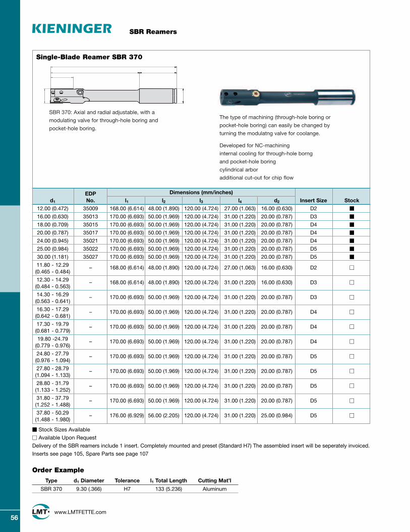
SBR Reamers
56www.LMTFETTE.com
Single-Blade Reamer SBR 370
EDP Dimensions (mm/inches)
d1 No. l1 l2 l3 l4 d2 Insert Size Stock
12.00 (0.472) 35009 168.00 (6.614) 48.00 (1.890) 120.00 (4.724) 27.00 (1.063) 16.00 (0.630) D2 m
16.00 (0.630) 35013 170.00 (6.693) 50.00 (1.969) 120.00 (4.724) 31.00 (1.220) 20.00 (0.787) D3 m
18.00 (0.709) 35015 170.00 (6.693) 50.00 (1.969) 120.00 (4.724) 31.00 (1.220) 20.00 (0.787) D4 m
20.00 (0.787) 35017 170.00 (6.693) 50.00 (1.969) 120.00 (4.724) 31.00 (1.220) 20.00 (0.787) D4 m
24.00 (0.945) 35021 170.00 (6.693) 50.00 (1.969) 120.00 (4.724) 31.00 (1.220) 20.00 (0.787) D4 m
25.00 (0.984) 35022 170.00 (6.693) 50.00 (1.969) 120.00 (4.724) 31.00 (1.220) 20.00 (0.787) D5 m
30.00 (1.181) 35027 170.00 (6.693) 50.00 (1.969) 120.00 (4.724) 31.00 (1.220) 20.00 (0.787) D5 m
11.80 - 12.29 (0.465 - 0.484)
– 168.00 (6.614) 48.00 (1.890) 120.00 (4.724) 27.00 (1.063) 16.00 (0.630) D2 M
12.30 - 14.29 (0.484 - 0.563)
– 168.00 (6.614) 48.00 (1.890) 120.00 (4.724) 31.00 (1.220) 16.00 (0.630) D3 M
14.30 - 16.29 (0.563 - 0.641)
– 170.00 (6.693) 50.00 (1.969) 120.00 (4.724) 31.00 (1.220) 20.00 (0.787) D3 M
16.30 - 17.29 (0.642 - 0.681)
– 170.00 (6.693) 50.00 (1.969) 120.00 (4.724) 31.00 (1.220) 20.00 (0.787) D4 M
17.30 - 19.79 (0.681 - 0.779)
– 170.00 (6.693) 50.00 (1.969) 120.00 (4.724) 31.00 (1.220) 20.00 (0.787) D4 M
19.80 -24.79 (0.779 - 0.976)
– 170.00 (6.693) 50.00 (1.969) 120.00 (4.724) 31.00 (1.220) 20.00 (0.787) D4 M
24.80 - 27.79 (0.976 - 1.094)
– 170.00 (6.693) 50.00 (1.969) 120.00 (4.724) 31.00 (1.220) 20.00 (0.787) D5 M
27.80 - 28.79 (1.094 - 1.133)
– 170.00 (6.693) 50.00 (1.969) 120.00 (4.724) 31.00 (1.220) 20.00 (0.787) D5 M
28.80 - 31.79 (1.133 - 1.252)
– 170.00 (6.693) 50.00 (1.969) 120.00 (4.724) 31.00 (1.220) 20.00 (0.787) D5 M
31.80 - 37.79 (1.252 - 1.488)
– 170.00 (6.693) 50.00 (1.969) 120.00 (4.724) 31.00 (1.220) 20.00 (0.787) D5 M
37.80 - 50.29 (1.488 - 1.980)
– 176.00 (6.929) 56.00 (2.205) 120.00 (4.724) 31.00 (1.220) 25.00 (0.984) D5 M
m Stock Sizes Available
M Available Upon Request
Delivery of the SBR reamers include 1 insert. Completely mounted and preset (Standard H7) The assembled insert will be seperately invoiced.
Inserts see page 105, Spare Parts see page 107
Order Example
Type d1 Diameter Tolerance l1 Total Length Cutting Mat’l
SBR 370 9.30 (.366) H7 133 (5.236) Aluminum
The type of machining (through-hole boring or
pocket-hole boring) can easily be changed by
turning the modulatng valve for coolange.
Developed for NC-machining
internal cooling for through-hole borng
and pocket-hole boring
cylindrical arbor
additional cut-out for chip flow
SBR 370: Axial and radial adjustable, with a
modulating valve for through-hole boring and
pocket-hole boring.

EDP Cutting
Lead-In Size No. Angle W Grade Description
35185 0 LW610 UC D2 R 0 LW610
35199 0 LC610Z UC D2 R 0 LC610Z
35195 6 LW610 UC D2 R 6 LW610
UC D235200 6 LC610Z UC D2 R 6 LC610Z
35202 12 LW610 UC D2 R 12 LW610
35201 12 LC610Z UC D2 R 12 LC610Z
35191 0 PCD UC D2 R 0 PCD
35183 0 CBN UC D2 R 0 CBN
35186 0 LW610 UC D3 R 0 LW610
35203 0 LC610Z UC D3 R 0 LC610Z
35196 6 LW610 UC D3 R 6 LW610
UC D335204 6 LC610Z UC D3 R 6 LC610Z
35206 12 LW610 UC D3 R 12 LW610
35205 12 LC610Z UC D3 R 12 LC610Z
35188 0 PCD UC D3 R 0 PCD
35192 0 CBN UC D3 R 0 CBN
35184 0 LW610 UC D4 R 0 LW610
35207 0 LC610Z UC D4 R 0 LC610Z
35197 6 LW610 UC D4 R 6 LW610
UC D435208 6 LC610Z UC D4 R 6 LC610Z
35209 12 LW610 UC D4 R 12 LW610
35213 12 LC610Z UC D4 R 12 LC610Z
35189 0 PCD UC D4 R 0 PCD
35193 0 CBN UC D4 R 0 CBN
35187 0 LW610 UC D5 R 0 LW610
35210 0 LC610Z UC D5 R 0 LC610Z
35198 6 LW610 UC D5 R 6 LW610
UC D535211 6 LC610Z UC D5 R 6 LC610Z
35214 12 LW610 UC D5 R 12 LW610
35212 12 LC610Z UC D5 R 12 LC610Z
35190 0 PCD UC D5 R 0 PCD
35194 0 CBN UC D5 R 0 CBN
All cutter Inserts cut in right hand direction.
SBR Reamers
57www.LMTFETTE.com
1.3
3°30°
Indexable Inserts
First choice Reamer Insert Blades designed for all materialgroups in providing superior finishes at high cutting speeds.
Order Example
EDP
12345
UC D2 R 12 LW610
LW610
Cutting Angle
Direction of Cut LH/RH
Insert Blade Size
Lead-In

SBR Reamers
58www.LMTFETTE.com
Available Upon Request
Special Profiles Size Cutting Angle Grade
LC D2 0° 6° 12° LW610 LC610Z PCD CBN
D3 0° 6° 12° LW610 LC610Z PCD CBN
D4 0° 6° 12° LW610 LC610Z PCD CBN
D5 0° 6° 12° LW610 LC610Z PCD CBN
SC D2 0° 6° 12° LW610 LC610Z PCD CBN
D3 0° 6° 12° LW610 LC610Z PCD CBN
D4 0° 6° 12° LW610 LC610Z PCD CBN
D5 0° 6° 12° LW610 LC610Z PCD CBN
HC D2 0° 6° 12° LW610 LC610Z PCD CBN
D3 0° 6° 12° LW610 LC610Z PCD CBN
D4 0° 6° 12° LW610 LC610Z PCD CBN
D5 0° 6° 12° LW610 LC610Z PCD CBN
CC D2 0° 6° 12° LW610 LC610Z PCD CBN
D3 0° 6° 12° LW610 LC610Z PCD CBN
D4 0° 6° 12° LW610 LC610Z PCD CBN
D5 0° 6° 12° LW610 LC610Z PCD CBN
GC D2 0° 6° 12° LW610 LC610Z PCD CBN
D3 0° 6° 12° LW610 LC610Z PCD CBN
D4 0° 6° 12° LW610 LC610Z PCD CBN
D5 0° 6° 12° LW610 LC610Z PCD CBN
Special Lead-In Inserts – Available Upon Request
3
1
3°15°
0.3
0.55
15°75°
1.3
0.7
3°
75°
0.6
0.3
3°30°
0.55
75°
Order Example
EDP
12345
LC D2 R 6 LW610 AL
Cutting Material
Cutter Material
Cutting Angle
Cutting Direction
Size
Lead-In

SBR Reamers
59www.LMTFETTE.com
Spare Parts No. 1 2 3 4 5 6 7
Coolant Insert Clamping Adjustable Axial Axial Setting mounting
Insert Screw Piece element Pin Screw valve (set)* d1 (H7) Blade EDP EDP EDP EDP EDP EDP
SBR 350, SBR 360
7.80 - 8.29 (0.307 - 0.326) D2 13192 13194 13206 – – –
8.30 - 8.79 (0.327 - 0.346) D2 13192 13194 13207 – – –
8.80 - 9.29 (0.346 - 0.366) D2 13192 13194 13207 – – –
9.30 - 11.29 (0.366 - 0.444) D2 13193 13195 13208 – – –
11.30 - 11.79 (0.444 - 0.464) D2 13193 13195 13209 – –
SBR 370
11.80 - 12.29 (0.465 - 0.484) D2 13193 13195 13209 13216 13221 13199
12.30 - 14.29 (0.484 - 0.563) D3 13193 13196 13209 13220 13221 13199
14.30 - 16.29 (0.563 - 0.641) D3 13193 13196 13210 13217 13222 13200
16.30 - 17.29 (0.642 - 0.681) D4 13191 13197 13211 13218 13223 13201
17.30 - 19.79 (0.681 - 0.779) D4 13191 13197 13212 13218 13223 13201
19.80 -24.79 (0.779 - 0.976) D4 13191 13197 13213 13218 13223 13202
24.80 - 27.79 (0.976 - 1.094) D5 13191 13198 13214 13219 13224 13203
27.80 - 28.79 (1.094 - 1.133) D5 13191 13198 13214 13219 13224 13203
28.80 - 31.79 (1.133 - 1.252) D5 13191 13198 13215 13219 13224 13203
31.80 - 37.79 (1.252 - 1.488) D5 13191 13198 13215 13219 13224 13204
37.80 - 50.29 (1.488 - 1.980) D5 13191 13198 13215 13219 13224 13205
*coolant mounting valve, O-ring, locking pin
Spare Parts
45 732
16
4 32
1
SBR 350 = radial adjustable, for pocket-boring
SBR 360 = radial adjustable, for through-boring
SBR 370 = axial and radial adjustable, with a modulating valve
for through-hole boring and pocket-hole boring

SBR Reamers
60www.LMTFETTE.com
S
H
Cutting Data Recommendations for External Coolant Supply
N
K
M
P
Cutting Angle Cutting Speed for External Coolant Supply
ISO Feed HM Code Material Rm/UTS (N/mm2) IPR 0 6 12 HM coated PCD CBN
Plain Carbon Steel < 950 .004-.012 m M70-130 70-130
*70-130 70-130
Free Cutting Steel < 950 .004-.012 m M70-130 70-130
*70-130 70-130
Structural Low Alloy Steel 500-950 .004-.012 m M70-130 70-130
*70-130 70-130
Heat-Treatable Steel 500-950 .004-.012 m M70-130 70-130
*70-130 70-130
Cast Steel < 950 .004-.012 M m70-130 70-130
*70-130 70-130
Case Hardening Steel < 950 .004-.012 m M70-130 70-130
*70-130 70-130
Stainless Steel, ferritic, 500-950 .004-.008 m M70-130 70-130
*martensitic 70-130 70-130
Nitriding Steel 950-1400 .004-.012 m M70-130 70-130
*70-130 70-130
Tool Steel 950-1400 .004-.012 m M70-130 70-130
*70-100 70-100
Stainless Steel, 500 - 950 .004-.008 M m 70-100 70-130
austenitic
Grey Cast Iron 100-400 (120-260 HB) .004-.012 M m 100-130 130-160 *
Alloyed Grey Cast Iron 150-250 (160-230 HB) .004-.012 M 100-130 130-160 *
Nodular Cast Iron 400 - 800 (120-310 HB) .004-.012 M m 100-130 130-160 *
Malleable Cast Iron 350 - 700 (150-280 HB) .004-.012 M m 100-130 130-160 *
Pure Metals, soft < 500 .004-.012 M m M 100-130 *
Aluminum Alloys, long chipping
< 500 .004-.012 m m M 100-130 *
Aluminum Alloys, short chipping
< 400 .003-.012 m M 100-130 *
Copper Alloys, long chipping
300-700 .004-.0085 m M 100-130 *
Copper Alloys, short chipping
< 500 .004-.012 M m 100-130 *
Magnesium Alloys 150 - 300 .004-.012 m M 100-130 *
Thermoplastics 40 - 70 *
Duroplastics 20 - 40
Titanium Alloys, medium strength
< 950 .003-.006 m M 70-130
Titanium Alloys, high strength
900-1400 .003-.006 m M 70-130
45-52 HRC * * *
Hardened Steel 53-59 HRC * *
60-65 HRC * *
* Please enquire for cutting dataM Preferred cutting anglem Recommended in special applicationsCutting data are guidelines which may need to be optimized in operation.

H
61www.LMTFETTE.com
SBR Reamers
Cutting Data Recommendations for Internal Coolant Supply
S
N
K
M
P
Cutting Angle Cutting Speed for Internal Coolant Supply
ISO Feed HM Code Material Rm/UTS (N/mm2) IPR 0 6 12 HM coated PCD CBN
Plain Carbon Steel < 950 .004-.012 m M200-260 200-260
*200-260 200-260
Free Cutting Steel < 950 .004-.012 m M200-260 200-260
*200-260 200-260
Structural Low Alloy Steel 500-950 .004-.012 m M200-260 200-260
*200-260 200-260
Heat-Treatable Steel 500-950 .004-.012 m M200-260 200-260
*200-260 200-260
Cast Steel < 950 .004-.012 M m200-260 200-260
*200-260 200-260
Case Hardening Steel < 950 .004-.012 m M200-260 200-260
*200-260 200-260
Stainless Steel, ferritic, 500-950 .004-.008 m M200-260 200-260
*martensitic 200-260 200-260
Nitriding Steel 950-1400 .004-.012 m M200-260 200-260
*200-260 200-260
Tool Steel 950-1400 .004-.012 m M200-260 200-260
*130-200 130-200
Stainless Steel, 500 - 950 .004-.008 M m 130-200 200-260
austenitic
Grey Cast Iron 100-400 (120-260 HB) .004-.012 M m 330-390 260-390 *
Alloyed Grey Cast Iron 150-250 (160-230 HB) .004-.012 M 330-390 260-390 *
Nodular Cast Iron 400 - 800 (120-310 HB) .004-.012 M m 330-390 260-390 *
Malleable Cast Iron 350 - 700 (150-280 HB) .004-.012 M m 330-390 260-390 *
Pure Metals, soft < 500 .004-.012 M m M 330-390 *
Aluminum Alloys, long chipping
< 500 .004-.012 m m M 330-390 *
Aluminum Alloys, short chipping
< 400 .003-.012 m M 330-390 *
Copper Alloys, long chipping
300-700 .004-.0085 m M 330-390 *
Copper Alloys, short chipping
< 500 .004-.012 M m 330-390 *
Magnesium Alloys 150 - 300 .004-.012 m M 330-390 *
Thermoplastics 40 - 70 *
Duroplastics 20 - 40
Titanium Alloys, medium strength
< 950 .003-.006 m M 200-260
Titanium Alloys, high strength
900-1400 .003-.006 m M 200-260
45-52 HRC * * *
Hardened Steel 53-59 HRC * *
60-65 HRC * *
* Please enquire for cutting dataM Preferred cutting anglem Recommended in special applicationsCutting data are guidelines which may need to be optimized in operation.
Pre-MachiningThe oversize for the reaming process should be chosen thatthe maximum roughness depth resulting from pre-machiningis less than the cutting depth of the reamer. The safest valuefrom a process viewpoint is a cutting depth of approx.0.15 mm (0.3 mm increase in diameter).
Coolants and LubricantsOur reamers give the best results when used with normalcoolants in mixing proportions 1:9. The guide bars shouldalways have a film of lubricant. Cutting data are guidelineswhich may need to be optimized in operations.

SBR Reamers
62www.LMTFETTE.com
Changing the Insert
Unscrew the setting screwsloosen both radial setting screws (1 full rotation)
Unscrew the insert holderunscrew the fixing screws for the insert holder
Changing insert- take out the insert- cleaning the insert seat- set in the cleaned or the new insert
Assembling the insert- push in the insert (axial and radial)- Screw in the fixing screws for the insert holder- insert will be moved in the insert seat automatically
Radial Pre-AdjustmentScrew in the radial setting screw (approx. 1 rotation)with a hexagon key
Axial Pre-Adjustmentaxial adjustment of the insert by screwing the settingscrew with a hexagon key
Fine-Adjustment- for the fine-adjustment we recommend a micrometer- adjust the front and back setting-dimension in turn
Fine adjust to the back approx. 0.01-0.015 mm

63www.LMTFETTE.com
FORMBORE System Tools – A new development in technology and economy
ProductsLMT-Fette is pleased to announce the introduction of our new FORMBORE System Tools.This unique line consists of three components: a driven shaft, body casing, and drill chuck.The rotating drive shaft is located in the body case. FORMBORE’s torque-driven controldetermines the movement sequence of the drill chuck. The movement of the cutting tool isby means of rolling-element sequences. FORMBORE System Tools are designed for differentprofiles, whether square or hexagon. FORMBORE makes it possible to make changes in themanufacturing process, potentially removing reaming, EDM or milling operations. FORMBORESystem Tools are designed to operate virtually wear and maintenance-free, and making itpossible to machine materials up to 27 Rc.
Application AreaFORMBORE System Tools are designed for use on turning lathes and machining centers aswell as drilling machines. Examples of special tooling systems vary from right-angled headunits and machining center v-flange head units to VDI holder types for turning lathes.FORMBORE System Tools are available in two sizes. Size 1 is suitable for speeds up to1000 maximum rpm, and forms squares from 4–14mm (0.1579–0.5519), and hexagons from4–21mm (0.1579–0.8279). Size 2 is suitable for speeds up to 500 maximum rpm, and formssquares from 4–22mm (0.1579–0.8669), and hexagons from 4–38mm (0.1579–0.1.4969).
MaterialsAs stated above, FORMBORE System Tools are designed for a broad range of materialgroups and Rockwell hardness up to 27 Rc. FORMBORE System Tools are designed asapplication-specific tooling for all manufacturing markets, whether job shop, automotive, or even aerospace.
AdvantagesFor the first time you can produce a large variety of inner and outer profiles with the highestprecision using a drilling machine, turning lathe, or machining center. FORMBORE SystemTools work independently from the machining spindle. It is not necessary to calculate andprogram the synchronized coordinates for a square or hexagon shape. FORMBORE SystemTools are designed for many unique profiles and profile sizes, and can potentially removecostly process steps in the manufacturing operation, such as reaming, EDM, or extra millingoperations.
Engineered to your specificapplication requirements
Contact your local LMT-Fetterepresentative for details
NEW

64www.LMTFETTE.com
FORMBORE System Tools – A new development in technology and economy
Designed for use on turning lathes and
machining centers as well as drilling
machines, FORMBORE System Tools provide
practical versatility, flexibility, time saving and
cost reduction in daily work.
The FORMBORE system consists of three
components: a driver shaft, body casing
and drill chuck, making it possible to make
changes in the manufacturing process
and to potentially remove reaming,
EDM or milling operations.
L
S I M P L Y V E R S A T I L E
w
Shown: Ordering recommendation for a FORMBORE System
Tool with cam block, eccentric bushing, insert holder
and cutting bodies.
FORMBORE cam block

Let us know your processing
requirements. You will receive
our specific tool recommendation
and our offer will convince you
of the advantages of the new
FORMBORE development.
with FORMBORE, you can produce
a large variety of inner & outer
profiles with high precision
CAT 40 SHANK
SHANK DRIVE VDI 40
RIGHT-ANGLE DRIVE
65www.LMTFETTE.com
FORMBORE System Tools – A new development in technology and economy

66www.LMTFETTE.com
Tangential Rolling Heads
ProductsLMT-Fette is pleased to announce the expansion to its Tangential Thread Rolling system with the addition of the new T120F, T160F, T220F, and T350F Thread Rolling Heads. LMT-Fette rolling attachments have been recognized around the world for economicallyproviding cold forming thread profiles on screw machines and CNC lathes. LMT-Fette hasdeveloped the new T3 digit F series rolling attachments to enhance the already wide rangeof sizes available to thread roll. The new T3 digit F series heads are capable of rolling5/649–29 thread sizes.
Application Area The T3 digit F series heads features fine adjustment for accurate sizing of fine-pitch threads.T350F Tangential Thread Rolling system is designed as a large capacity head capable ofrolling sizes from 1/49–29 threads. All the T3 digit F series attachments can be setup quicklyeven outside the machine. Because of the symmetrical adjustment of the rolls with thesetting screw, it can be adjusted to the exact setting. The body of the T3 digit F seriesattachments has been improved with more than 20% less structural length, makinginstallation on all CNC lathes possible.
Materials The T3 digit F series Tangential Thread Rolling attachments can be applied to materials thathave an elongation factor of greater than 5% and material hardness up to 32 Rc. Theseconditions provide optimum roll life, depending on the number parts produced.
AdvantagesThe heads in LMT-Fette’s full line of Tangential systems are known for easy, quick setup. The T3 digit F series is the answer fine pitch profiles and large profile sizes. The new T3 digitF series Thread Rolling system is designed to cover a wide range of thread sizes and widths.The T3 digit F series is capable of rolling thread behind the shoulder. They are the optimalsolution for threads that are short in length. The T3 digit F series are also designed for theNPT (NPTF) thread family from 1/169–1-1/29. They have been optimized with new, safe setuproll drives, and new carbide drive axles for high stability and long head life.
NEW

67www.LMTFETTE.com
Tangential Rolling Heads
Rolling Attachment T120F T160F T220F T350F
Model No. 2408491 2408423 2407499 2408020
b1 mm/inch 43.0/1.693 50.0/1.969 70.0/2.756 99.0/3.898
b2 mm/inch/max. 15.5/0.610 18.5/0.728 26.0/1.024 36.0/1.417
b3 mm/inch 7.20/0.283 8.50/0.335 13.3/0.524 18.0/0.709
L1 mm/inch/min. 23.2/0.913 28.2/1.110 37.2/1.465 61.2/2.407
L1 mm/inch/max. 27.6/1.087 33.4/1.315 46.9/1.846 73.3/2.886
L2 mm/inch 10.0/0.394 13.0/0.512 17.0/0.669 27.0/1.063
L3 mm/inch/min. 50.0/1.969 53.0/2.087 74.0/2.913 110.0/4.331
L4 mm/inch 66.0/2.598 75.2/2.961 107.5/4.232 169.5/6.673
h1 mm/inch/min. 26.5/1.043 32.0/1.260 48.0/1.890 68.0/2.677
h1 mm/inch/max. 40.0/1.575 48.0/1.890 74.4/2.929 105.5/4.154
h2 mm/inch 16.3/0.642 19.9/0.783 23.5/0.925 39.7/1.563
d mm/inch/max. 31.5/1.240 37.5/1.476 53.0/2.087 80.0/3.150
Rolling Attachment – Kg/lbs. 0.65/1.430 1.30/2.870 3.20/7.060 12.5/27.56
Rolling Attachment Holder – Kg/lbs. 0.75/1.650 1.70/3.750 4.30/9.480 7.00/15.44
Thread Roll – Kg/lbs. 0.17/0.370 0.30/0.660 0.85/1.870 2.60/5.730
Total – Kg/lbs. 1.57/3.460 3.30/7.280 8.35/18.41 22.1/48.73
Tangential Side Thread Rolling Attachment T120F, T160F, T220F, T350F
AV
h2 h1 h2
Pre-adjustmentDimension
L2
L1C
ente
rto
Cen
ter
Dis
tanc
e
Sha
nkTy
pe
d max
b3 b2b1
L3
L4

68www.LMTFETTE.com
Tangential Rolling Heads
T120F T160F T220F T350FPart No. Qty. Part Description EDP No. EDP No. EDP No. EDP No.
1 Rolling attachment without Holder 2408491 2408423 2407499 240802011) 1 Upper arm
2401302 2172710 2172146 240802321) 1 Lower are with pin3 2 Shaft 2401305 2172305 2172149 24080264 1 Center shaft 2173414 2170305 2172150 24080275 1 Bushing 2408655 2408464 2407438 24080286 1 Bushing 2408656 2408465 2407439 24080297 2 Bearing bushing 2173417 2170308 2172153 24080308 2 Pinion 2401306 2170309 2172154 24080319 2 Tension Spring 2401307 2172731 2172155 240804310 2 Gear with bushing 2173420 2170310 2172156 240803211 1 Gear set with coil spring (Parts 11, 12, 16) 2174927 2170311 2172157 240803313 2 Bushing 2408647 2408466 2407382 240803715 2 Thrust Washer 2173425 2170316 2172161 240803816 1 Balance spring (see part no. 11) 2173426 2170317 2172162 240803518 2 Thread Roll See Individual Config.21 2 Grease Nipple 2149168 2149168 2149168 214916824 2 Cap screw 2141877 2141885 2141899 214191525 2 Set screw 2142157 2142157 2142159 214217526 4 Straight pin resp. clamping sleeve 2400230 2142565 2213197 240804227 1 Set screw 2142118 2148369 2148369 214213028 2 Locking screw 2141877 2141878 2408449 2141904
29 L 1 Spindle nut (LH) 2401308 2170323 2172163 240803929 R 1 Spindle nut (RH) 2401309 2170322 2172164 240804030 1 Spindle 2401310 2172827 2404015 240804133 2 DIN 1474 pin (see part no. 2 and 5) 2148843 2148843 2148843 214884234 2 Centering ring – 2172080 2172778 240804435 2 Lock washer 2149270 2149269 2149271 214927436 1 Reference gage 2401311 2170320 2172166 240804537 2 Set screw 2142114 2142115 2142119 214212731 1 Attachment Holder Complete, depending on type of machine
31 - 1 1 Basic Housing Individual31 - 4 1 Bolt Individual31 - 5 1 For Example VDI-shank Individual31 - 6 1 Spring Clip holder complete 2401352 2172817 2172817 240869531 - 8 1 Set Screw 2142173 2142138 2142138 214209431 - 12 2 Set Screw 2142112 2142112 2142112 214212931 - 17 1 Cap Screw Individual
32 1 Setting gage Individual1) To be used and available only in one piece.
Spare Parts of RollingAttachments T120F, T160F,T220F, T350F

69www.LMTFETTE.com
Axial Rolling Heads
ProductsLMT-Fette is pleased to announce the new Axial F Series and Axial K Series Thread Rolling Heads with flexible-shank connections. This new connection allows one head to fit on several shank types, and on different machines. Shank types available are straight, VDI, HSK, Cat, and Capto.
Application AreaThe Axial F Series and K Series Thread Rolling Heads are ideal for shops that require flexibility from one machine to another without purchasing dedicated heads for eachmachine.
AdvantagesLMT-Fette’s full line of Thread Rolling Heads with new, flexible connections allow use on multiple machines, whether a Lathe Center or Machining Center, requiring specific shanks.
NEW

Axial Rolling Heads
70www.LMTFETTE.com
for right-hand threads
Type F0 C1to be used stationary only
Type K0 C1used stationary or rotating
inclined position of rolls = 4°weight without rolls = approx. 0.5kg(1.1 lbs.)
Cat. No. 7101for left-hand threads
Type F0L C1 resp. KOL C1Dimensions as right-hand threads
Change Shanks
Type . . . -C1Cat. No. 71510 VDI Shank
Otherse.g. Tapered
Shanks (upon request)
Rolling Head EDP No.
F0 C1 2430900
F0L C1 2430901
K0 C1 2430902
K0L C1 2430903
Dimensions mm/inch
D 50mm/1.968
D1max. 54.5mm/2.146
D2 11.5mm/.453
D6 M5
D81) 55mm/2.165
D7 6.5mm/.256
L2a 46mm/1.811
L5 5mm/.197
L6 5.7mm/.224
L81) 13.9mm/.547
a 2mm/.079
α 50°
ß1) 10°1)only for Type K
R20-C1 R25-C1 R3/4-C1 R1-C1 R1 1/4-C1 VDI20-C1 VDI25-C1 VDI30-C1 HSK-A63-C1
Dimensions Shank Shank Shank Shank Shank Shank Shank Shank Shankmm/inch 20mm Ø /.787 25mm Ø / .984 3/40 Ø 10 Ø 1-1/40 Ø VDI20 VDI25 VDI30 HSK-A63
D4 20mm/.787 25mm/.984 19.05mm..750 25.4mm/1.000 31.75mm/1.250 20mm/.787 25mm/.984 30mm/1.181 48mm/1.890
D9 – – – – – 50mm/1.969 58mm/2.283 68mm/2.677 63mm/2.480
L 108.5mm/4.272 108.5mm/4.272 108.5mm/4.272 108.5mm/4.272 108.5mm/4.272 104.5mm/4.114 112.5mm/4.429 119.5mm/4.705 121mm/4.764
L2 48.5mm/1.909 48.5mm/1.909 48.5mm/1.909 48.5mm/1.909 48.5mm/1.909 64.5mm/2.539 64.5mm/2.539 64.5mm/2.539 89mm/3.504
L3 60mm/2.362 60mm/2.362 60mm/2.362 60mm/2.362 60mm/2.362 40mm/1.575 48mm/1.890 55mm/2.165 32mm/1.260
L4 – – – – – 62mm/2.440 97mm/3.819 104mm/4.094 54mm/2.126
EDP No. 2430980 2430973 2430981 2430977 2430982 2430984 2430986 2430988 2430990
Shanks will be delivered with the according fastening screws.
Straight Shank(with Flat
upon request)HSK Shank
a 4 Pull off for openingb 4 Head opens when Type K0 or F0L
Head closes when Type F0 or K0Lc 4 Head closes when Type K0 or F0L
Head opens when Type F0 or K0Ld 4 Rolling head closede 4 Rolling head opendedf 4 Thread for handleα 4 Closing angle

Axial Rolling Heads
71www.LMTFETTE.com
Spare Parts for Rolling Heads F0 C1 and K0 C1
Rolling Head F0 C1 F0L C1 1) K0 C1 K0L C1 1)
Catalog Number 7101 7101 7101 7101Part No. Qty. Part Description EDP No. EDP No. EDP No. EDP No.
Rolling head complete without shank 2) 2430900 2430901 2430902 24309031 1 Clutch 2430904 2430905 24309042 1 Spring housing 2164502 2164511 2164543 21689193 1 Centre plate 2164503 2164516 2164544 21689204 1 Front plate 2164504 2164519 2164545 21689215 2 Eccentric spindles 21645056 2 Spacer studs 21645067 1 Centre gear 2164507 2164520 2164507 21645208 2 Spur gear 21645089 1 Guide bushing individual10 1 Coil spring 2164512 2164521 216451211 1 Circlip 216451312 1 Circlip 216451413 2 Carbide bushing 216747214 2 Front plate screw 214248815 2 Hexagon nut 214839716 1 Ring washer 216451517 1 Hexagon nut 214839718 2 Thread roll individual19 1 Washer 214886723 1 Ball 214169924 2 Set screw 3) 2142064 + 2142062 + 214206525 1 Handle 2148840
Part 1 (Clutch) combined with the according shank from the selection list (see page before) are the replacement for the previously known shaft.Existent rolling heads can be easily retrofitted. Rolling Heads can also be delivered with closing rod, closing roller and closing spring, instead of handle.When ordering spare parts, please state Thread Rolling Head Type, Part No. and EDP No.1) L = For Left-hand threads2) The shank which fits your application you see in the selection on page 70. Please order seperately.3) Part 24 not shown in the view (Locking screws for Adjustment with Type K).
Internal stop* IS0-C1 IS0L-C1 1)
Catalog Number 71511 71511Part No. Qty. Part Description EDP No. EDP No.
Internal stop complete 2430906 243090820 1 Stop screw body 2430907 243090921 1 Stop screw 2164518 216452322 1 Hexagon nut 2168387 2168389
*Only required for machines without controlled feed stop. If required, please order additionally.1) L = For Left-hand threads

Dimensions mm/inch
D 64mm/2.520
D1max. 70mm/2.756
D2 17mm/.669
D6 M5-Type “K” /
M6-Type “F”
D7 11.4mm/.449
D8 1) 64mm/2.520
L2a 57mm/2.244
L5 6mm/.236
L6 7.5mm/.295
L8 1) 9.5mm/.374
a 2mm/.079
α 60°
ß 1) 10°1)only for Type K
Axial Rolling Heads
72www.LMTFETTE.com
for right-hand threads
Type F1 C1to be used stationary only
Type K1 C1used stationary or rotating
inclined position of rolls = 3° 30'weight without rolls = approx. 0.8kg(1.76 lbs.)
Cat. No. 7104for left-hand threads
Type F1L C1 resp. K1L C1Dimensions as right-hand threads
Change Shanks
Type . . . -C1Cat. No. 71510
R20-C1 R25-C1 R3/4-C1 R1-C1 R1 1/4-C1 VDI20-C1 VDI25-C1 VDI30-C1 HSK-A63-C1
Dimensions Shank Shank Shank Shank Shank Shank Shank Shank Shankmm/inch 20mm/.787 Ø 25mm/.984 Ø 3/40 Ø 10 Ø 1-1/40 Ø VDI20 VDI25 VDI30 HSK-A63
D4 20mm/.787 25mm/.984 19.05mm/.750 25.4mm/1.000 31.75mm/1.250 20mm/.787 25mm/.984 30mm/1.181 48mm/1.890
D9 – – – – – 50mm/1.969 58mm/2.283 68mm/2.677 63mm/2.480
L 119.5mm/4.705 119.5mm/4.705 119.5mm/4.705 119.5mm/4.705 119.5mm/4.705 115.5mm/4.547 123.5mm/4.862 130.5mm/5.138 132mm/5.197
L2 59.5mm/2.343 59.5mm/2.343 59.5mm/2.343 59.5mm/2.343 59.5mm/2.343 75.5mm/2.972 75.5mm/2.972 75.5mm/2.974 100mm/3.937
L3 60mm/2.362 60mm/2.362 60mm/2.362 60mm/2.362 60mm/2.362 40mm/1.575 48mm/1.890 55mm/2.165 32mm/1.260
L4 – – – – - 72mm/2.835 107mm/4.213 114mm/4.488 64mm/2.520
EDP No. 2430980 2430973 2430981 2430977 2430982 2430984 2430986 2430988 2430990
Shanks will be delivered with the according fastening screws.
VDI Shank
Otherse.g. Tapered
Shanks (upon request)
a 4 Pull off for openingb 4 Head opens when Type K1 or F1L
Head closes when Type F1 or K1Lc 4 Head closes when Type K1 or F1L
Head opens when Type F1 or K1Ld 4 Rolling head closede 4 Rolling head opendedf 4 Thread for handleα 4 Closing angle
Straight Shank(with Flat
upon request)HSK Shank
Rolling Head EDP No.
F1 C1 2430910
F1L C1 2430911
K1 C1 2430912
K1L C1 2430913

Axial Rolling Heads
73www.LMTFETTE.com
Spare Parts for Rolling Heads F1 C1 and K1 C1
Rolling Head F1 C1 F1L C1 1) K1 C1 K1L C1 1)
Catalog Number 7104 7104 7104 7104Part No. Qty. Part Description EDP No. EDP No. EDP No. EDP No.
Rolling head complete without shank 2) 2430910 2430911 2430912 24309131 1 Clutch 2430914 2430915 24309142 1 Spring housing 2164634 2164649 2164719 21647223 1 Centre plate 2164635 2164650 2164720 21647234 1 Front plate 2164636 2164651 2164721 21647245 3 Eccentric spindles 21646376 3 Spacer studs 21646387 1 Centre gear 2164639 2164652 2164639 21646528 3 Spur gear 21646409 1 Handle 2148841 214884010 1 Coil spring 2164641 2164653 216464111 1 Circlip 216464212 1 Circlip 216464313 3 Carbide bushing 216470514 3 Cap screw 214873615 3 Hexagon nut 214839716 1 Ring washer 216464417 1 Hexagon nut 2148393 214839718 3 Thread roll individual19 2 Set screw 3) 214206419 1 Set screw 3) 214206219 1 Set screw 3) 214206523 1 Ball 2141700 214169924 1 Washer 2144250 2148867
Part 1 (Clutch) combined with the according shank from the selection list (see page before) are the replacement for the previously known shaft.Existent rolling heads can be easily retrofitted. Rolling Heads can also be delivered with closing rod, closing roller and closing spring, instead of handle.When ordering spare parts, please state Thread Rolling Head Type, Part No. and EDP No.1) L = For Left-hand threads2) The shank which fits your application you see in the selection on page 72. Please order seperately.3) Part 19 not shown in the view (Locking screws for Adjustment with Type K).
Internal stop* IS1-C1 IS1L-C1 1)
Catalog Number 71511 71511Part No. Qty. Part Description EDP No. EDP No.
Internal stop complete 2430916 243091720 1 Stop screw body 2164645 216465421 1 Stop screw 2164646 216465522 1 Hexagon nut 2166124 2166125
*Only required for machines without controlled feed stop. If required, please order additionally.1) L = For Left-hand threads

Axial Rolling Heads
74www.LMTFETTE.com
Change Shanks
Type . . . -C1Cat. No. 71510
R20-C1 R25-C1 R3/4-C1 R1-C1 R1 1/4-C1 VDI20-C1 VDI25-C1 VDI30-C1 HSK-A63-C1
Dimensions Shank Shank Shank Shank Shank Shank Shank Shank Shank mm/inch 20mm/.787 Ø 25mm/.984 Ø 3/40 Ø 10 Ø 1-1/40 Ø VDI20 VDI25 VDI30 HSK-A63
D4 20mm/.787 25mm/.984 19.05mm/.750 25.4mm/1.000 31.75mm/1.250 20mm/.787 25mm/.984 30mm/1.181 48mm/1.890
D9 – – – – – 50mm/1.969 58mm/2.283 68mm/2.677 63mm/2.480
L 120.5mm/4.744 120.5mm/4.744 120.5mm/4.744 120.5mm/4.744 120.5mm/4.744 116.5mm/4.587 124.5mm/4.902 131.5mm/5.177 133mm/5.236
L2 60.5mm/2.381 60.5mm/2.381 60.5mm/2.381 60.5mm/2.381 60.5mm/2.381 76.5mm/3.012 76.5mm/3.012 76.5mm/3.012 101mm/3.976
L3 60mm/2.362 60mm/2.362 60mm/2.362 60mm/2.362 60mm/2.362 40mm/1.575 48mm/1.890 55mm/2.165 32mm/1.260
L4 – – – – – 73mm/2.874 108mm/4.252 115mm/4.528 65mm/2.559
EDP No. 2430980 2430973 2430981 2430977 2430982 2430984 2430986 2430988 2430990
Shanks will be delivered with the according fastening screws.
VDI Shank
Otherse.g. Tapered
Shanks (upon request)
a 4 Pull off for openingb 4 Head opens when Type K12 or F12L
Head closes when Type F12 or K12Lc 4 Head closes when Type K12 or F12L
Head opens when Type F12 or K12Ld 4 Rolling head closede 4 Rolling head opendedf 4 Thread for handleα 4 Closing angle
Straight Shank(with Flat
upon request)HSK Shank
Rolling Head EDP No.
F12 C1 2430918
F12L C1 2430919
K12 C1 2430938
K12L C1 2430939
Dimensions mm/inch
D 64mm/2.520
D1max. 70mm/2.756
D2 20mm/.787
D6 M5-Type “K” /
M6-Type “F”
D7 11.4mm/.449
D8 1) 64mm/2.520
L2a 58mm/2.283
L5 6mm/.236
L6 7.5mm/.295
L8 1) 9.5mm/.375
a 2mm/.079
α 60°
ß 1) 10°1)only for Type K
for right-hand threads
Type F12 C1to be used stationary only
Type K12 C1used stationary or rotating
inclined position of rolls = 1° 50'weight without rolls = approx. 0.8kg(1.76 lbs.)
Cat. No. 7105for left-hand threads
Type F12L C1 resp. K12L C1Dimensions as right-hand threads

Axial Rolling Heads
75www.LMTFETTE.com
Spare Parts for Rolling Heads F12 C1 and K12 C1
Rolling Head F12 C1 F12L C1 1) K12 C1 K12L C1 1)
Catalog Number 7105 7105 7105 7105Part No. Qty. Part Description EDP No. EDP No. EDP No. EDP No.
Rolling head complete without shank 2) 2430918 2430919 2430938 24309391 1 Clutch 2430914 2430915 24309142 1 Spring housing 2164634 2164649 2164719 21647223 1 Centre plate 2164735 2164742 2164756 21647584 1 Front plate 2164736 2164743 2164757 21647595 3 Eccentric spindles 21647376 3 Spacer studs 21647387 1 Centre gear 2164739 2164744 2164739 21647448 3 Spur gear 21647409 1 Handle 2148841 214884010 1 Coil spring 2164641 2164653 216464111 1 Circlip 216464212 1 Circlip 216464313 3 Carbide bushing 217351214 3 Cap screw 214873615 3 Hexagon nut 214839716 1 Ring washer 216464417 1 Hexagon nut 2148393 214839718 3 Thread roll individual19 2 Set screw 3) 214206419 1 Set screw 3) 214206219 1 Set screw 3) 214206523 1 Ball 2141700 214169924 1 Washer 2144250 214886725 3 Washer 2164741
Part 1 (Clutch) combined with the according shank from the selection list (see page before) are the replacement for the previously known shaft.Existent rolling heads can be easily retrofitted. Rolling Heads can also be delivered with closing rod, closing roller and closing spring, instead of handle.When ordering spare parts, please state Thread Rolling Head Type, Part No. and EDP No.1) L = For left-hand threads2) The shank which fits your application you see in the selection on page 74. Please order seperately.3) Part 19 not shown in the view (Locking screws for Adjustment with Type K).
Internal stop* IS1-C1 IS1L-C1 1)
Catalog Number 71511 71511Part No. Qty. Part Description EDP No. EDP No.
Internal stop complete 2430916 243091720 1 Stop screw body 2164645 216465421 1 Stop screw 2164646 216465522 1 Hexagon nut 2166124 2166125
*Only required for machines without controlled feed stop. If required, please order additionally.1) L = For Left-hand threads

Axial Rolling Heads
76www.LMTFETTE.com
for right-hand threads
Type F1223 C1to be used stationary only
Type K1223 C1used stationary or rotating
inclined position of rolls = 1° 50'weight without rolls = approx. 0.8kg(1.76 lbs.)
Cat. No. 7106for left-hand threads
Type F1223L C1 resp. K1223L C1Dimensions as right-hand threads
R20-C1 R25-C1 R3/4-C1 R1-C1 R1-1/4-C1 VDI20-C1 VDI25-C1 VDI30-C1 HSK-A63-C1
Dimensions Shank Shank Shank Shank Shank Shank Shank Shank Shankmm/inch 20mm/.787 Ø 25mm/.984 Ø 3/40 Ø 10 Ø 1-1/40 Ø VDI20 VDI25 VDI30 HSK-A63
D4 20mm/.787 25mm/.984 19.05mm/.750 25.4mm/1.000 31.75mm/1.250 20mm/.787 25mm/.984 30mm/1.181 48mm/1.890
D9 – – – – – 50mm/1.969 58mm/2.283 68mm/2.677 63mm/2.480
L 120.5mm/4.744 120.5mm/4.744 120.5mm/4.744 120.5mm/4.744 120.5mm/4.744 116.5mm/4.587 124.5mm/4.902 131.5mm/5.177 133mm/5.236
L2 60.5mm/2.381 60.5mm/2.381 60.5mm/2.381 60.5mm/2.381 60.5mm/2.381 76.5mm/3.012 76.5mm/3.012 76.5mm/3.012 101mm/3.976
L3 60mm/2.362 60mm/2.362 60mm/2.362 60mm/2.362 60mm/2.362 40mm/1.575 48mm/1.890 55mm/2.165 32mm/1.260
L4 – – – – – 74mm/2.913 109mm/2.291 116mm/4.670 66mm/2.598
EDP No. 2430980 2430973 2430981 2430977 2430982 2430984 2430986 2430988 2430990
Shanks will be delivered with the according fastening screws.
VDI Shank
Otherse.g. Tapered
Shanks (upon request)
a 4 Pull off for openingb 4 Head opens when Type K1223 or F1223L
Head closes when Type F1223 or K1223Lc 4 Head closes when Type K1223 or F1223L
Head opens when Type F1223 or K1223Ld 4 Rolling head closede 4 Rolling head opendedf 4 Thread for handleα 4 Closing angle
Straight Shank(with Flat
upon request)HSK Shank
Change Shanks
Type . . . -C1Cat. No. 71510
Rolling Head EDP No.
F1223 C1 2430920
F1223L C1 2430921
K1223 C1 2430922
K1223L C1 2430923
Dimensions mm/inch
D 56mm/2.205
D1max. 58mm/2.283
D2 16mm/.630
D6 M5-Type “K” /
M8x1-Type “F”
D7 8.2mm/.323
D8 1) 56mm/2.205
L2a 58mm/2.283
L5 5mm/.197
L6 7.5mm/.295
L8 1) 9.5mm/.375
a 2mm/.079
α 50°
ß 1) 10°1)only for Type K

Axial Rolling Heads
77www.LMTFETTE.com
Spare Parts for Rolling Heads F1223 C1 and K1223 C1
Rolling Head F1223 C1 F1223L C1 1) K1223 C1 K1223L C1 1)
Catalog Number 7106 7106 7106 7106Part No. Qty. Part Description EDP No. EDP No. EDP No. EDP No.
Rolling head complete without shank 2) 2430920 2430921 2430922 24309231 1 Clutch 2430924 2430925 24309242 1 Spring housing 2164821 2168914 2164837 21672193 1 Centre plate 2164822 2168909 2164838 22415524 1 Front plate 2164823 2168910 2164839 22415535 3 Eccentric spindles 21648246 3 Spacer studs 21648257 1 Centre gear 2164826 2168911 2164826 21689118 3 Spur gear 21648279 1 Closing rod / Handle 2164828 214884010 1 Coil spring 2164829 2164840 216482911 1 Circlip 216483012 1 Circlip 216483113 3 Carbide bushing 216889214 3 Cap screw 214873615 3 Hexagon nut 214839716 1 Ring washer 216483217 1 Hexagon nut 214839718 3 Thread roll individual19 2 Set screw 3) 214206319 1 Set screw 3) 214206119 1 Set screw 3) 214206523 1 Ball 214169924 1 Washer 2144251 2148867
Part 1 (Clutch) combined with the according shank from the selection list (see page before) are the replacement for the previously known shaft.Existent rolling heads can be easily retrofitted. Rolling Heads can also be delivered with closing rod, closing roller and closing spring, instead of handle.When ordering spare parts, please state Thread Rolling Head Type, Part No. and EDP No.1) L = For Left-hand threads2) The shank which fits your application you see in the selection on page 76. Please order seperately.3) Part 19 not shown in the view (Locking screws for Adjustment with Type K).
Internal stop* IS1223-C1 IS1223L-C1 1)
Catalog Number 71511 71511Part No. Qty. Part Description EDP No. EDP No.
Internal stop complete 2430926 243092820 1 Stop screw body 2164833 216891221 1 Stop screw 2430927 243092922 1 Hexagon nut 2168388 2168398
*Only required for machines without controlled feed stop. If required, please order additionally.1) L = For Left-hand threads

Axial Rolling Heads
78www.LMTFETTE.com
for right-hand threads
Type F2 C2to be used stationary only
Type K2 C2used stationary or rotating
inclined position of rolls = 3°weight without rolls = approx. 1.8kg(3.96 lbs.)
Cat. No. 7107for left-hand threads
Type F2L C2 resp. K2L C2Dimensions as right-hand threads
Change Shanks
Type . . . -C2Cat. No. 71510
R25-C2 R30-C2 R1-C2 R1 1/4-C2 R1 1/2-C2 VDI25-C2 VDI30-C2 VDI40-C2 HSK-A63-C2
Dimensions Shank Shank Shank Shank Shank Shank Shank Shank Shankmm/inch 25mm/.984 Ø 30mm/1.181 Ø 10 Ø 1-1/40 Ø 1-1/20 Ø VDI25 VDI30 VDI40 HSK-A63
D4 25mm/.984 30mm/1.181 25.4mm/1.000 31.75mm/1.250 38.1mm/1.500 25mm/.984 30mm/1.181 40mm/1.575 48mm/1.890
D9 – – – – – 58mm/2.283 68mm/2.677 83mm/3.268 63mm/2.481
L 152mm/5.984 176mm/6.574 152mm/5.984 167mm/6.574 167mm/6.574 141mm/5.612 148mm/5.787 156mm/6.141 150mm/5.905
L2 77mm/3.032 77mm/3.032 77mm/3.032 77mm/3.032 77mm/3.032 93mm/2.874 93mm/2.874 93mm/2.874 118mm/4.646
L3 75mm/2.953 90mm/3.543 75mm/2.953 90mm/3.543 90mm/3.543 48mm/1.890 55mm/2.166 63mm/2.481 32mm/1.260
L4 – – – – – 90mm/3.543 123mm 134mm 84mm
EDP No. 2249897 2430967 2249899 2430969 2430971 2249901 2249903 2249905 2249907
Shanks will be delivered with the according fastening screws
VDI Shank
Otherse.g. Tapered
Shanks (upon request)
a 4 Pull off for openingb 4 Head opens when Type K2 or F2L
Head closes when Type F2 or K2Lc 4 Head closes when Type K2 or F2L
Head opens when Type F2 or K2Ld 4 Rolling head closede 4 Rolling head opendedf 4 Thread for handleα 4 Closing angle
Straight Shank(with Flat
upon request)HSK Shank
Rolling Head EDP No.
F2 C2 2249894
F2L C2 2430931
K2 C2 2430932
K2L C2 2430933
Dimensions mm/inch
D 88mm/3.465
D1max. 93.5mm/3.681
D2 24mm/.944
D6 M6
D7 17mm
D8 1) 88mm/3.465
L2a 74.5mm/2.933
L5 7.5mm/.295
L6 16.8mm/.661
L8 1) 9mm/.354
a 3mm/.118
α 60°
ß 1) 10°1)only for Type K

Axial Rolling Heads
79www.LMTFETTE.com
Spare Parts for Rolling Heads F2 C2 and K2 C2
Rolling Head F2C2 F2L C2 1) K2 C2 K2L C2 1)
Catalog Number 7107 7107 7107 7107Part No. Qty. Part Description EDP No. EDP No. EDP No. EDP No.
Rolling head complete without shank 2) 2249894 2430931 2430932 24309331 1 Clutch 2249896 2430935 22498962 1 Spring housing 2164767 2164782 2164896 21648993 1 Centre plate 2164768 2164783 2164897 21649004 1 Front plate 2164769 2164784 2164898 21649015 3 Eccentric spindles 21647706 3 Spacer studs 21647717 1 Centre gear 2164772 2164785 2164772 21647858 3 Spur gear 21647739 1 Handle 214884110 1 Coil spring 2164774 2164786 216477411 1 Circlip 216477512 1 Circlip 216477613 3 Carbide bushing 216488714 3 Cap screw 214299915 3 Hexagon nut 214839316 1 Ring washer 216477717 1 Hexagon nut 214839318 3 Thread roll individual19 2 Set screw 3) 214207719 1 Set screw 3) 214207519 1 Set screw 3) 214207823 1 Ball 214170024 1 Washer 2144250
Part 1 (Clutch) combined with the according shank from the selection list (see page before) are the replacement for the previously known shaft.Existent rolling heads can be easily retrofitted. Rolling Heads can also be delivered with closing rod, closing roller and closing spring, instead of handle.When ordering spare parts, please state Thread Rolling Head Type, Part No. and EDP No.1) L = For Left-hand threads2) The shank which fits your application you see in the selection on page 78. Please order seperately.3) Part 19 not shown in the view (Locking screws for Adjustment with Type K).
Internal stop* IS2-C2 IS2L-C2 1)
Catalog Number 71511 71511Part No. Qty. Part Description EDP No. EDP No.
Internal stop complete 2430936 243093720 1 Stop screw body 2164779 216478721 1 Stop screw 2164778 216478822 1 Hexagon nut 2148390 2148700
*Only required for machines without controlled feed stop. If required, please order additionally.1) L = For Left-hand threads

Axial Rolling Heads
80www.LMTFETTE.com
for right-hand threads
Type F23 C2to be used stationary only
Type K23 C2used stationary or rotating
inclined position of rolls = 1° 25'weight without rolls = approx. 1.8 kg(3.97 lbs.)
Cat. No. 7109for left-hand threads
Type F23L C2 resp. K23L C2Dimensions as right-hand threads
Change Shanks
Type . . . -C2Cat. No. 71510
R25-C2 R30-C2 R1-C2 R1 1/4-C2 R1 1/2-C2 VDI25-C2 VDI30-C2 VDI40-C2 HSK-A63-C2
Dimensions Shank Shank Shank Shank Shank Shank Shank Shank Shank mm/inch 25mm/.984 Ø 30mm/1.182 Ø 10 Ø 1-1/40 Ø 1-1/20 Ø VDI25 VDI30 VDI40 HSK-A63
D4 25mm/.984 30mm/1.182 25.4mm/1.000 31.75mm/1.250 38.1mm/1.500 25mm/.984 30mm/1.182 40mm/1.575 48mm/1.890
D9 – – – – – 58mm/2.284 68mm/2.678 83mm/3.268 63mm/2.481
L 153mm/6.030 168mm/6.620 153mm/6.030 168mm/6.620 168mm/6.620 142mm/5.590 149mm/5.870 157mm/6.190 151mm/5.950
L2 78mm/3.070 78mm/3.070 78mm/3.070 78mm/3.070 78mm/3.070 94mm/3.700 94mm/3.700 94mm/3.700 119mm/4.690
L3 75mm/2.953 90mm/3.544 75mm/2.953 90mm/3.544 90mm/3.544 48mm/1.890 55mm/2.166 63mm/2.481 32mm/1.260
L4 – – – – – 91mm/3.583 124mm/4.882 135mm/5.315 85mm/3.347
EDP No. 2249897 2430967 2249899 2430969 2430971 2249901 2249903 2249905 2249907
Shanks will be delivered with the according fastening screws.
VDI Shank
Otherse.g. Tapered
Shanks (upon request)
a 4 Pull off for openingb 4 Head opens when Type K23 or F23L
Head closes when Type F23 or K23Lc 4 Head closes when Type K23 or F23L
Head opens when Type F23 or K23Ld 4 Rolling head closede 4 Rolling head opendedf 4 Thread for handleα 4 Closing angle
Straight Shank(with Flat
upon request)HSK Shank
Rolling Head EDP No.
F23 C2 2430940
F23L C2 2430941
K23 C2 2430942
K23L C2 2430943
Dimensions mm/inch
D 88mm/3.465
D1max. 93.5mm/3.682
D2 28mm/1.103
D6 M6
D7 17mm/.670
D8 1) 88mm/3.465
L2a 75.5mm/2.980
L5 7.5mm/.296
L6 16.8mm/.662
L8 1) 9mm/.355
a 3mm/.118
α 60°
ß 1) 10°1)only for Type K

Axial Rolling Heads
81www.LMTFETTE.com
Spare Parts for Rolling Heads F23 C2 and K23 C2
Rolling Head F23 C2 F23L C2 1) K23 C2 K23L C2 1)
Catalog Number 7108 7108 7108 7108Part No. Qty. Part Description EDP No. EDP No. EDP No. EDP No.
Rolling head complete without shank 2) 2430940 2430941 2430942 24309431 1 Clutch 2249896 2430935 22498962 1 Spring housing 2164767 2164782 2164896 21648993 1 Centre plate 2164929 2164936 2164927 21672844 1 Front plate 2164930 2164937 2164928 21672855 3 Eccentric spindles 21649316 3 Spacer studs 21649327 1 Centre gear 2164933 2164938 2164933 21649388 3 Spur gear 21649349 1 Handle 214884110 1 Coil spring 2164774 2164786 216477411 1 Circlip 216477512 1 Circlip 216477613 3 Carbide bushing 216470514 3 Cap screw 214299915 3 Hexagon nut 214839316 1 Ring washer 216477717 1 Hexagon nut 214839318 3 Thread roll individual19 2 Set screw 3) 214207719 1 Set screw 3) 214207519 1 Set screw 3) 214207823 1 Ball 214170024 1 Washer 214425025 3 Washer 2164935
Part 1 (Clutch) combined with the according shank from the selection list (see page before) are the replacement for the previously known shaft.Existent rolling heads can be easily retrofitted. Rolling Heads can also be delivered with closing rod, closing roller and closing spring, instead of handle.When ordering spare parts, please state Thread Rolling Head Type, Part No. and EDP No.1) L = For Left-hand threads2) The shank which fits your application you see in the selection on page 80. Please order seperately.3) Part 19 not shown in the view (Locking screws for Adjustment with Type K).
Internal stop* IS2-C2 IS2L-C2 1)
Catalog Number 71511 71511Part No. Qty. Part Description EDP No. EDP No.
Internal stop complete 2430936 243093720 1 Stop screw body 2164779 216478721 1 Stop screw 2164778 216478822 1 Hexagon nut 2148390 2148700
*Only required for machines without controlled feed stop. If required, please order additionally.1) L = For Left-hand threads

82
Axial Rolling Heads
for right-hand threads
Type F233400 C2to be used stationary only
Type K233400 C2used stationary or rotating
inclined position of rolls = 1° 15'weight without rolls = approx. 2.7kg(5.95 lbs.)
Cat. No. 7109for left-hand threads
Type F233400L C2 resp.K233400L C2Dimensions as right-hand threads
Change Shanks
Type . . . -C2Cat. No. 71510
R25-C2 R30-C2 R1-C2 R1 1/4-C2 R1 1/2-C2 VDI25-C2 VDI30-C2 VDI40-C2 HSK-A63-C2
Dimensions Shank Shank Shank Shank Shank Shank Shank Shank Shankmm/inch 25mm/.984 Ø 30mm/1.182 Ø 10 Ø 1-1/40 Ø 1-1/20 Ø VDI25 VDI30 VDI40 HSK-A63
D4 25mm/.984 30mm/1.182 25.4mm/1.000 31.75mm/1.250 38.1mm/1.500 25mm/.984 30mm/1.182 40mm/1.575 48mm/1.890
D9 – – – – – 58mm/2.284 68mm/2.678 83mm/3.268 63mm/2.481
L 168.5mm/6.640 183.5mm/7.230 168.5mm/6.640 183.5mm/7.230 183.5mm/7.230 157.5mm/6.200 164.5mm/6.480 172.5mm/6.800 166mm/6.540
L2 93.5mm/3.690 93.5mm/3.690 93.5mm/3.690 93.5mm/3.690 93.5mm/3.690 109.5mm/4.320 109.5mm/4.320 109.5mm/4.320 134mm/5.280
L3 75mm/2.953 90mm/3.544 75mm/2.953 90mm/3.544 90mm/3.544 48mm/1.890 55mm/2.166 63mm/2.481 32mm/1.260
L4 73mm/2.874 3) 73mm/2.874 3) 3) 73mm/2.874 98mm/3.859 150mm/5.966 100mm/3.937
EDP No. 2249897 2430967 2249899 2430969 2430971 2249901 2249903 2249905 2249907
Shanks will be delivered with the according fastening screws.3) L4 = 73mm for threads, which are larger than 22.2mm (major diameter)
VDI Shank
Otherse.g. Tapered
Shanks (upon request)
a 4 Pull off for openingb 4 Head opens when Type K233400 or F233400L
Head closes when Type F233400 or K233400Lc 4 Head closes when Type K233400 or F233400L
Head opens when Type F233400 or K233400Ld 4 Rolling head closede 4 Rolling head opendedf 4 Thread for handleα 4 Closing angle
Straight Shank(with Flat
upon request)HSK Shank
Rolling Head EDP No.
F233400 C2 2430944
F233400L C2 2430945
K233400 C2 2430946
K233400L C2 2430947
Dimensions mm/inch
D 96mm/3.780
D1max. 115mm/4.528
D2 39mm/1.536
D6 M6-Type “K” /
M8-Type “F”
D7 28mm/1.110 2)
22.5mm/.890 2)
D8 1) 96mm/3.780
L2a 91mm/3.590
L5 8mm/.315
L6 9mm/.355
L8 1) 9.5mm/.375
a 3mm/.118
α 30°
ß 1) 10°1)only for Type K
www.LMTFETTE.com

83
Axial Rolling Heads
Spare Parts for Rolling Heads F233400C2 and K233400C2
Rolling Head F233400 C2 F233400L C2 1) K233400 C2 K233400L C2 1)
Catalog Number 7109 7109 7109 7109Part No. Qty. Part Description EDP No. EDP No. EDP No. EDP No.
Rolling head complete without shank 2) 2430944 2430945 2430946 24309471 1 Clutch 2430948 2430949 24309482 1 Spring housing 2164966 2164983 2165004 21685953 1 Centre plate 2164967 2164984 2165005 22406144 1 Front plate 2164968 2164985 2165006 22406135 3 Eccentric spindles 21649696 3 Spacer studs 21649707 1 Centre gear 2164971 2164986 2164971 21649868 3 Spur gear 21649729 1 Closing rod / Handle 2164973 214884110 1 Coil spring 2164974 2164987 216497411 1 Circlip 216497512 1 Circlip 216497613 3 Carbide bushing 216823714 3 Cap screw 214300715 3 Hexagon nut 214839816 1 Ring washer 216497717 1 Hexagon nut 214839318 3 Thread roll individual19 2 Set screw 3) 214207819 1 Set screw 3) 214207619 1 Set screw 3) 214207923 1 Ball 214170024 1 Washer 2144251 214425025 3 Washer 2164978
Part 1 (Clutch) combined with the according shank from the selection list (see page before) are the replacement for the previously known shaft.Existent rolling heads can be easily retrofitted. Rolling Heads can also be delivered with closing rod, closing roller and closing spring, instead of handle.When ordering spare parts, please state Thread Rolling Head Type, Part No. and EDP No.1) L = For Left-hand threads2) The shank which fits your application you see in the selection on page 82. Please order seperately.3) Part 19 not shown in the view (Locking screws for Adjustment with Type K).
for shank-diameter25mm, 25.4mm 30mm, 31.75mm, 38.1mm
Internal stop* IS233400-C2 IS233400L-C2 IS3-C2 IS3L-C2Catalog Number 71511 71511 71511 71511
Part No. Qty. Part Description EDP No. EDP No. EDP No. EDP No.Internal stop complete 2430950 2430951 2430954 2430955
20 1 Stop screw body 2164779 2164787 2165036 216504621 1 Stop screw 2430952 2430953 2165037 216504722 1 Hexagon nut 2148390 2148700 2148391 2148702
*Only required for machines without controlled feed stop. If required, please order additionally.

Axial Rolling Heads
84www.LMTFETTE.com
for right-hand threads
Type F3 C2to be used stationary only
Type K3 C2used stationary or rotating
inclined position of rolls = 2° 40'weight without rolls = approx. 3.5kg(7.71 lbs.)
Cat. No. 7110for left-hand threads
Type F3L C2 resp. K3L C2Dimensions as right-hand threads
Change Shanks
Type . . . -C2Cat. No. 71510
R25-C2 R30-C2 R1-C2 R1 1/4-C2 R1 1/2-C2 VDI25-C2 VDI30-C2 VDI40-C2 HSK-A63-C2
Dimensions Shank Shank Shank Shank Shank Shank Shank Shank Shank mm/inch 25mm/.984 Ø 30mm/1.182 Ø 10 Ø 1-1/40 Ø 1-1/20 Ø VDI25 VDI30 VDI40 HSK-A63
D4 25mm/.984 30mm/1.182 25.4mm/1.000 31.75mm/1.250 38.1mm/1.500 25mm/.984 30mm/1.182 40mm/1.575 48mm/1.890
D9 – – – – – 58mm/2.284 68mm/2.678 83mm/3.268 63mm/2.481
L 167mm/6.580 182mm/7.170 167mm/6.580 182mm/7.170 182mm/7.170 156mm/6.150 163mm/6.420 171mm/6.750 167mm/6.580
L2 92mm/3.630 92mm/3.630 92mm/3.630 92mm/3.630 92mm/3.630 108mm/4.250 108mm/4.250 108mm/4.250 133mm/5.240
L3 75mm/2.953 90mm/3.544 75mm/2.953 90mm/3.544 90mm/3.544 48mm/1.890 55mm/2.166 63mm/2.481 32mm/1.260
L4 – – – – – 72mm/2.840 96mm/3.780 148mm/5.830 99mm/3.900
EDP No. 2249897 2430967 2249899 2430969 2430971 2249901 2249903 2249905 2249907
Shanks will be delivered with the according fastening screws.
VDI Shank
Otherse.g. Tapered
Shanks (upon request)
a 4 Pull off for openingb 4 Head opens when Type K3 or F3L
Head closes when Type F3 or K3Lc 4 Head closes when Type K3 or F3L
Head opens when Type F3 or K3Ld 4 Rolling head closede 4 Rolling head opendedf 4 Thread for handleα 4 Closing angle
Straight Shank(with Flat
upon request)HSK Shank
Rolling Head EDP No.
F3 C2 2430956
F3L C2 2430957
K3 C2 2430958
K3L C2 2430959
Dimensions mm/inch
D 117mm/4.607
D1max. 131mm/5.158
D2 38mm/1.496
D6 M8
D7 22.5mm/.886
D8 1) 117mm/4.607
L2a 89.5mm/3.530
L5 8mm/.315
L6 17.5mm/.689
L8 1) 9.5mm/.375
a 4mm/.158
α 60°
ß 1) 10°1)only for Type K

Axial Rolling Heads
85www.LMTFETTE.com
Spare Parts for Rolling Heads F3 C2 and K3 C2
Rolling Head F3 C2 F3L C2 1) K3 C2 K3L C2 1)
Catalog Number 7110 7110 7110 7110Part No. Qty. Part Description EDP No. EDP No. EDP No. EDP No.
Rolling head complete without shank 2) 2430956 2430957 2430958 24309591 1 Clutch 2430960 2430961 24309602 1 Spring housing 2165025 2165042 2165453 21654563 1 Centre plate 2165026 2165041 2165454 21654574 1 Front plate 2165027 2165043 2165455 21654585 3 Eccentric spindles 21650286 3 Spacer studs 21650297 1 Centre gear 2165030 2165044 2165030 21650448 3 Spur gear 21650319 1 Handle 216702010 1 Coil spring 2165032 2165045 216503211 1 Circlip 216503312 1 Circlip 216503413 3 Carbide bushing 216507214 3 Cap screw 214300715 3 Hexagon nut 214839816 1 Ring washer 216503517 1 Hexagon nut 214839818 3 Thread roll individual19 2 Set screw 3) 216714819 1 Set screw 3) 214207619 1 Set screw 3) 214208023 1 Ball 214170124 1 Washer 2144251
Part 1 (Clutch) combined with the according shank from the selection list (see page before) are the replacement for the previously known shaft.Existent rolling heads can be easily retrofitted. Rolling Heads can also be delivered with closing rod, closing roller and closing spring, instead of handle.When ordering spare parts, please state Thread Rolling Head Type, Part No. and EDP No.1) L = For Left-hand threads2) The shank which fits your application you see in the selection on page 84. Please order seperately.3) Part 19 not shown in the view (Locking screws for Adjustment with Type K).
Internal stop* IS3-C2 4) IS3L-C2 1) 4)
Catalog Number 71511 71511Part No. Qty. Part Description EDP No. EDP No.
Internal stop complete 2430954 234095520 1 Stop screw body 2165036 216504621 1 Stop screw 2165037 216504722 1 Hexagon nut 2148391 2148702
*Only required for machines without controlled feed stop. If required, please order additionally.1) L = For Left-hand threads
4) not available for shank-diameter 25mm and 1.000

Axial Rolling Heads
86www.LMTFETTE.com
for right-hand threads
Type F34 C2to be used stationary only
Type K34 C2used stationary or rotating
inclined position of rolls = 1° 15'weight without rolls = approx. 3.5kg(7.71 lbs.)
Cat. No. 7111for left-hand threads
Type F34L C2 resp. K34L C2Dimensions as right-hand threads
Change Shanks
Type . . . -C2Cat. No. 71510
R25-C2 R30-C2 R1-C2 R1 1/4-C2 R1 1/2-C2 VDI25-C2 VDI30-C2 VDI40-C2 HSK-A63-C2
Dimensions Shank Shank Shank Shank Shank Shank Shank Shank Shankmm/inch 25mm/.984 Ø 30mm/1.182 Ø 10 Ø 1-1/40 Ø 1-1/20 Ø VDI25 VDI30 VDI40 HSK-A63
D4 25mm/.984 30mm/1.182 25.4mm/1.000 31.75mm/1.250 38.1mm/1.500 25mm/.984 30mm/1.182 40mm/1.575 48mm/1.890
D9 – – – – – 58mm/2.284 68mm/2.678 83mm/3.268 63mm/2.481
L 168.5mm/6.640 183.5mm/7.230 168.5mm/6.640 183.5mm/7.250 183.5mm/7.250 157.5mm/6.200 164.5mm/6.480 172.5mm/6.800 168.5mm/6.640
L2 93.5mm/3.690 93.5mm/3.690 93.5mm/3.690 93.5mm/3.690 93.5mm/3.690 109.5mm/3.690 109.5mm/3.690 109.5mm/3.690 134.5mm/5.300
L3 75mm/2.953 90mm/3.544 75mm/2.953 90mm/3.544 90mm/3.544 48mm/1.890 55mm/2.166 63mm/2.481 32mm/1.260
L4 – – – – – 73mm/2.880 97mm/3.820 149mm/5.870 100mm/3.940
EDP No. 2249897 2430967 2249899 2430969 2430971 2249901 2249903 2249905 2249907
Shanks will be delivered with the according fastening screws.
VDI Shank
Otherse.g. Tapered
Shanks (upon request)
a 4 Pull off for openingb 4 Head opens when Type K34 or F34L
Head closes when Type F34 or K34Lc 4 Head closes when Type K34 or F34L
Head opens when Type F34 or K34Ld 4 Rolling head closede 4 Rolling head opendedf 4 Thread for handleα 4 Closing angle
Straight Shank(with Flat
upon request)HSK Shank
Rolling Head EDP No.
F34 C2 2430962
F34L C2 2430963
K34 C2 2430964
K34L C2 2430965
Dimensions mm/inch
D 117mm/4.607
D1max. 128mm/5.040
D2 44mm/1.733
D6 M8
D7 22.5mm/.886
D8 1) 117mm/4.607
L2a 91mm/3.590
L5 8mm/.315
L6 17.5mm/.689
L8 1) 9.5mm/.375
a 4mm/.158
α 60°
ß 1) 10°1)only for Type K

Axial Rolling Heads
87www.LMTFETTE.com
Spare Parts for Rolling Heads F34C2 and K34C2
www.LMTFETTE.com
Rolling Head F34 C2 F34L C2 1) K34 C2 K34L C2 1)
Catalog Number 7111 7111 7111 7111Part No. Qty. Part Description EDP No. EDP No. EDP No. EDP No.
Rolling head complete without shank 2) 2430962 2430963 2430964 24309651 1 Clutch 2430960 2430961 24309602 1 Spring housing 2165025 2165042 2165453 21654563 1 Centre plate 2165532 2165540 2165571 21683834 1 Front plate 2165533 2165541 2165572 21683845 3 Eccentric spindles 21655346 3 Spacer studs 21655357 1 Centre gear 2165536 2165542 2165536 21655428 3 Spur gear 21655379 1 Handle 216702010 1 Coil spring 2165032 21655045 216503211 1 Circlip 216503312 1 Circlip 216503413 3 Carbide bushing 216488714 3 Cap screw 214300715 3 Hexagon nut 214839816 1 Ring washer 216503517 1 Hexagon nut 214839818 3 Thread roll individual19 2 Set screw 3) 216714819 1 Set screw 3) 214207619 1 Set screw 3) 214208023 1 Ball 214170124 1 Washer 214425125 3 Washer 2165539
Part 1 (Clutch) combined with the according shank from the selection list (see page before) are the replacement for the previously known shaft.Existent rolling heads can be easily retrofitted. Rolling Heads can also be delivered with closing rod, closing roller and closing spring, instead of handle.When ordering spare parts, please state Thread Rolling Head Type, Part No. and EDP No.1) L = For Left-hand threads2) The shank which fits your application you see in the selection on page 86. Please order seperately.3) Part 19 not shown in the view (Locking screws for Adjustment with Type K).
Internal stop* IS3-C2 4) IS3L-C2 1) 4)
Catalog Number 71511 71511Part No. Qty. Part Description EDP No. EDP No.
Internal stop complete 2430954 234095520 1 Stop screw body 2165036 216504621 1 Stop screw 2165037 216504722 1 Hexagon nut 2148391 2148702
*Only required for machines without controlled feed stop. If required, please order additionally.1) L = For Left-hand threads
4) not available for shank-diameter 25mm and 1.000

88www.LMTFETTE.com
ProductsLMT-Fette is pleased to announce the introduction of Bilz’ superior THERMO-GRIPTM
technology to our product offering. The Bilz company, another member of the LMT group, isworld renowned for their tap holding product line, as well as the industry leader in Shrink-Fittool holding technology. This new THERMO-GRIP product addition marks LMT-Fette’s debutin the tool holding market. The new technology compliments LMT-Fette’s complete solidcarbide and indexable milling product line for both the die and mold and aerospaceindustries.
Application AreaShrink-Fit technology was introduced primarily to compliment the relatively new introductionof high-speed machining to the North American market. In the die and mold industry, as well as in aerospace, the tremendous accuracy and repeatability of the Shrink-Fit concepthas significantly reduced cycle times, improved work piece accuracy, and offeredtremendous tool life. Because of these dramatic results, this technology is now showing upin the automotive industry, as well as the general machining market. Any high-volume, ortight tolerance milling or drilling application will benefit from the merits of Shrink-Fittechnology. When used with solid carbide end mills or drills, one can expect to see improvedwork piece accuracy, and the noticeably improved tool life outlined above.
MaterialsBilz THERMO-GRIPTM technology performs exceptionally in all materials. It is commonly used for machining P20, H13, and S7 in the die and mold industry, but also is heavily usedin the machining of aluminum components in the aerospace and automotive industries.
AdvantagesAs shown, THERMO-GRIPTM technology provides unsurpassed work piece accuracy, as well as tremendous tool life. The Bilz product line offers a choice of inexpensive units for the beginner in the ISG2200, as well as the universal, and slightly more expensive unit in the ISG3200. The ISG3200 features a unique coil changing system that allows you to optimizethe performance of the unit for the tools you are using. Additionally, both products feature an automatic return mechanism for the coil, eliminating the possibility of overheating.
BILZ THERMO-GRIPTM Shrink-Fit Units and Holders

89www.LMTFETTE.com
BILZ THERMO-GRIPTM Shrink-Fit Units and Holders
ISG 2200 – The starter model in the class of Shrink-Fit Units
Mobile Unit for use in the tool presetting area or locally atthe machine.
The mobile unit type ISG 2200, represents an inexpensive initialmove into inductive shrinking technology. The low weight meansthat it can be used flexibly wherever it is required. Despite thecompact design, it allows tool changing for diameters 1/49–3/49
within seconds. The clamping range can be reduced down to 3 mm with the optional available plate changing kit. The integratedfan cools down the clamping chucks quickly. The ISG 2200 offersall the features for easy and safe use of shrinking technology inyour facility. Suitable for carbide tools only.
The coil is moved manually to the required heating position.There it is fixed by pressing the button. After the heating operationthe coil returns automatically. Overheating of the coil and clampingchuck is therefore avoided.
Clamping range 6–20 mm (1/49–3/49 )Suitable tool shanks carbide toolsOperation manualTool setting measuring adaptorCoil integratedPlate –Max. tool length 290 mm (11.4179 )(from gauge line)Cooling stations 1Air pressure –Electric current supply 3 x 208 V
79010 15.35 12.20 25.19 3 – 20 mm Carbide 3 x 208 V/16 A 3 551/49 – 3/49
EDP No.
Technical Data: ISG 2200
D W HElectric current
supply Clamping
range Suitable tool mate-
rialsWeight
lbs.Power
kW
ISG 2200

90www.LMTFETTE.com
BILZ THERMO-GRIPTM Shrink-Fit Units and Holders
ISG 3200 – The performance class for continual tool changing
Universal table unitOn the fully automatically controlled ISG 3200 unit all that needs to be done is simply to select the tool diameter range. After thestart button is pressed, the induction coil moves automatically tothe toolholder, heats this sufficiently and moves back againautomatically.
ISG 3200 is a universal shrinking unit for the professional use ofshrinking technology. With its unique coil changing system, thepower transfer adjusted to the different clamping chucks is
Clamping range 3–6 mm (1/89–1/49 carbide)Clamping range 6–32 mm (1/49–1-1/49 carbide+HSS)Clamping range 32–50 mm (1-1/49–29 - optional)
carbide+HSSOperation automaticTool setting measuring adaptorCoil exchangeablePlate –Max. tool length 450 mm (17.719 )(from gauge line)Cooling stations 4Air pressure 87 PSIElectric current supply 3 x 400 V
ISG 3200 the universal unit
55781 22.99 23.31 40.55 3 – 50 mm Carbide+HSS 3 x 400 V/16 A 10 951/89 – 29
EDP No.
Technical Data: ISG 3200
guaranteed within a short period of time. Compared to othersystems, this makes it possible to clamp the smallest diameters Ø 6-50 mm (1/49–29 ) with high speed tools as well as down to Ø 3 mm (1/89 ) with carbide tools. With a range of special coils, the unit can be suited to other special tools. Four integrated fansmake it possible to cool down the clamping chucks evenly in ashort time. The fans are activated automatically by a light barrieras soon as the chuck is pushed into the cooling position. Thismeans that constant preparation of a high number of tools can be guaranteed.
D W HElectric current
supply Clamping
range Suitable tool mate-
rialsWeight
lbs.Power
kW

91www.LMTFETTE.com
A
A
N
l1
4.5°
0.003
d1 d2 d3
A
BILZ THERMO-GRIPTM Shrink-Fit Units and Holders
Dimensions (inches)
d1* EDP No. A d2 d3 l1 N
0.250 79087 3.740 0.787 1.063 1.417 0.394
0.375 50765 3.740 0.945 1.260 1.653 0.394
0.500 50764 3.740 1.063 1.339 1.850 0.394
0.625 79089 3.740 1.063 1.339 1.968 0.394
0.750 79090 3.740 1.299 1.653 2.047 0.394
1.000 79091 4.330 1.732 2.087 2.283 0.394
CAT40 THERMO-GRIPTM Clamping Chuck – Inch Diameter
Dimensions (inches)
d1* EDP No. A d2 d3 l1 N
6.0mm (0.236) 79045 3.150 0.787 1.063 1.417 0.394
8.0mm (0.315) 53841 3.150 0.787 1.063 1.417 0.394
10.0mm (0.394) 79046 3.150 0.945 1.260 1.653 0.394
12.0mm (0.472) 53842 3.150 0.945 1.260 1.850 0.394
16.0mm (0.630) 53843 3.150 1.063 1.339 1.968 0.394
20.0mm (0.787) 79047 3.150 1.181 1.339 2.047 0.394
25.0mm (0.984) 53844 3.937 1.732 2.087 2.283 0.394
CAT40 THERMO-GRIPTM Clamping Chuck – Metric Diameter
*Shank tolerance h6. Length adjustment N: 10 mm for all clamping diameters.All clamping chucks can be run with internal coolant.
*Shank tolerance h6. Length adjustment N: 10 mm for all clamping diameters.All clamping chucks can be run with internal coolant.
A
A
N
l1
4.5°
0.003
d1 d2 d3
A

92www.LMTFETTE.com
A
A
N
l1
4.5°
0.003
d1 d2 d3
A
BILZ THERMO-GRIPTM Shrink-Fit Units and Holders
Dimensions (inches)
d1* EDP No. A d2 d3 l1 N
0.250 79092 3.740 0.787 1.063 1.417 0.394
0.375 79093 3.740 0.945 1.260 1.653 0.394
0.500 79094 3.740 1.063 1.339 1.850 0.394
0.625 79098 3.740 1.063 1.339 1.968 0.394
0.750 79095 3.740 1.299 1.653 2.047 0.394
1.000 79096 4.134 1.732 2.087 2.283 0.394
1.250 79097 4.134 1.732 2.087 2.283 0.394
CAT50 THERMO-GRIPTM Clamping Chuck – Inch Diameter
Dimensions (inches)
d1* EDP No. A d2 d3 l1 N
6.0mm (0.236) 79058 3.740 0.787 1.063 1.417 0.394
8.0mm (0.315) 79059 3.740 0.787 1.063 1.417 0.394
10.0mm (0.394) 79060 3.740 0.945 1.260 1.653 0.394
12.0mm (0.472) 79061 3.740 0.945 1.260 1.850 0.394
16.0mm (0.630) 79063 3.740 1.063 1.339 1.850 0.394
20.0mm (0.787) 79065 3.740 1.299 1.339 2.047 0.394
25.0mm (0.984) 79066 4.134 1.732 2.087 2.283 0.394
32.0mm (1.260) 79067 4.134 1.732 2.087 2.283 0.394
CAT50 THERMO-GRIPTM Clamping Chuck – Metric Diameter
A
A
N
l1
4.5°
0.003
d1 d2 d3
A
*Shank tolerance h6Length adjustment N: 10 mm for all clamping diameters.All clamping chucks can be run with internal coolant.Please order coolant tube separately.
*Shank tolerance h6Length adjustment N: 10 mm for all clamping diameters.All clamping chucks can be run with internal coolant.Please order coolant tube separately.

93www.LMTFETTE.com
BILZ THERMO-GRIPTM Shrink-Fit Units and Holders
Dimensions (inches)
d1* EDP No. A d2 d3 l1 N
0.250 79069 3.150 0.787 1.063 1.417 0.394
0.312 79070 3.150 0.787 1.063 1.417 0.394
0.375 79071 3.346 0.945 1.260 1.653 0.394
0.500 79073 3.543 1.063 1.338 1.850 0.394
0.625 79075 3.740 1.063 1.338 1.968 0.394
0.750 79076 3.937 1.299 1.653 2.047 0.394
1.000 79078 4.724 1.732 2.086 2.283 0.394
1.250 79079 4.724 1.732 2.086 2.283 0.394
HSK-A63 THERMO-GRIPTM Clamping Chuck – Inch Diameter
Dimensions (inches)
d1* EDP No. A d2 d3 l1 N
6.0mm (0.236) 79048 3.150 0.787 1.063 1.417 0.394
8.0mm (0.315) 79049 3.150 0.787 1.063 1.417 0.394
10.0mm (0.394) 79050 3.346 0.945 1.260 1.653 0.394
12.0mm (0.472) 79051 3.543 0.945 1.338 1.850 0.394
16.0mm (0.630) 79053 3.740 1.063 1.338 1.968 0.394
20.0mm (0.787) 79054 3.937 1.299 1.653 2.047 0.394
25.0mm (0.984) 79055 4.527 1.732 2.086 2.283 0.394
32.0mm (1.260) 79056 4.724 1.732 2.086 2.283 0.394
HSK-A63 THERMO-GRIPTM Clamping Chuck – Metric Diameter
A
A
N
l1
4,5°
0,003
d3
A
9
d2d1
Design with shoulder (W) l
*Shank tolerance h6All clamping chucks can be run with internal coolant.Please order coolant tube separately.
A
A
N
l1
4,5°
0,003
d3
A
9
d2d1
Design with shoulder (W) l
*Shank tolerance h6All clamping chucks can be run with internal coolant.Please order coolant tube separately.

94www.LMTFETTE.com
BILZ THERMO-GRIPTM Shrink-Fit Units and Holders
Dimensions (inches)
d1 EDP No. d d2 d3 N A l10.250 79145 0.472 0.591 0.787 0.394 2.362 1.417
0.375 79146 0.787 0.787 1.063 0.394 2.362 1.653
0.500 79147 0.787 0.945 1.260 0.394 2.362 1.850
0.625 79148 0.984 0.945 1.260 0.394 2.362 1.968
Straight Shank THERMO-GRIPTM Extensions for Clamping Chuck – Inch Diameter
Dimensions (inches)
d1 EDP No. d d2 d3 N A l13.0mm (0.118) 53473 0.472 0.354 0.591 0.394 2.362 0.787
4.0mm (0.157) 53474 0.472 0.354 0.591 0.394 2.362 0.787
5.0mm (0.197) 53475 0.472 0.354 0.591 0.394 2.362 0.787
6.0mm (0.236) 53476 0.472 0.591 0.748 0.394 2.362 1.417
8.0mm (0.315) 53477 0.472 0.591 0.748 0.394 2.362 1.417
10.0mm (0.394) 53478 0.787 0.787 1.063 0.394 2.362 1.653
12.0mm (0.472) 53479 0.787 0.787 1.063 0.394 2.362 1.653
16.0mm (0.630) 53480 0.984 0.945 1.260 0.394 .2.362 1.968
Straight Shank THERMO-GRIPTM Extensions for Clamping Chuck – Metric Diameter
A
A
N
l1
4,5°
0,003
d1 d2 d3
A
d
For diameter 3, 4 and 5 shank tolerance h4 or betterFor diameter 6–16 shank tolerance h6
Length adjustment N for diameter 3, 4, 5: 5mmLength adjustment N for diameter 6-16: 10mmAll extensions can be run with internal coolant.
A
A
N
l1
4,5°
0,003
d1 d2 d3
A
d
For diameter 3, 4 and 5 shank tolerance h4 or betterFor diameter 6–16 shank tolerance h6
Length adjustment N for diameter 3, 4, 5: 5mmLength adjustment N for diameter 6-16: 10mmAll extensions can be run with internal coolant.

95www.LMTFETTE.com
BILZ THERMO-GRIPTM Shrink-Fit Units and Holders
HSK 32 56169HSK 40 56170HSK 50 56171HSK 63 56172HSK 80 56173HSK 100 56174
Accessories
HSK 32 HSK 32-10 56163HSK 40 HSK 40-12 56164HSK 50 HSK 50-16 56165HSK 63 HSK 63-18 56166HSK 80 HSK 80-20 56167HSK 100 HSK 100-24 56168
HSK sizes Designation EDP No.Coolant pipe for HSK chuckFor optimizing the internal coolant supply for HSKtools incl. round gasket DIN 3770 and union nut.
Installation wrench for coolant pipe
Tool Cart for ISG 3200/ISG 2000 – EDP No. 56175 The tool cart makes the ISG mobile. All accessories such asoils, tool holders, cooling and measuring adaptors, as well asthe clamping chucks fit in the sliding racks.
HSK sizes EDP No.

96www.LMTFETTE.com
BILZ THERMO-GRIPTM Shrink-Fit Units and Holders
Accessories
Designation EDP No.T3-WSD 56162
Compressed air unit
The newly developed ejection unit enables broken tools to beremoved simply from chucks. Even tools where the point ofbreakage is within the toolholder can be removed withoutdifficulty. The basic toolholder can be adapted to all customarymachine interfaces (HSK, CAT) by means of different adapters.*Even with a tight fit (bore diameter/tool shank) the shrunk-inshanks can be removed without difficulty. Further interfaces on request.
*Available upon request.
Ejection device for broken tools
Designation EDP No.T3-WSG 56153
Basic Toolholder

97www.LMTFETTE.com
BILZ THERMO-GRIPTM Shrink-Fit Units and Holders
Accessories
THERMO-GRIPTM Quick Change System
The ISG 3200 Shrink-Fit Unit already has a coil with a quickchange mechanism in the standard version. This enables eventools in special dimensions to be shrunk in and out withcorrespondingly adapted coils. The area of application of theinduction units can thus be extended permanently without havingto invest constantly in new unit technology.
Induction Coils
Changing Plates 3–32 ISGS 3200-1 5578232–50 ISGS 3200-2 55783
3–6 ISGS 3201-0 561826–12 ISGS 3201-1 55784
>12–20 ISGS 3201-2 55785>20–32 ISGS 3201-3 55786
Clamping Ø Designation EDP No.Induction Coil for ISG 3200
Changing Plates for ISG 3200 for Coil ISG 3200-1
The large number of special coils available for different specialtools illustrate benefits of the unique THERMO-GRIP® changingsystem. In the case of the universal coil already included with theunit, the different clamping ranges are obtained using 3 changingplates. Thus the most important clamping diameters of 6-32 mmcan be covered with one coil.

98www.LMTFETTE.com
BILZ THERMO-GRIPTM Shrink-Fit Units and Holders
T3-W/HSK 32 79017T3-W/HSK 40 79018T3-W/HSK 50 79019T3-W/HSK 63 79020T3-W/HSK 80 79021T3-W/HSK 100 79016
T3-W/SK 40 50756T3-W/SK 50 79022
Accessories
Tool Holders Designation EDP No.
for CAT clamping chucks
for ABS/Capto/clamping chucks
for HSK clamping chucks
T3-W/25 55746T3-W/32 55747T3-W/40 55748T3-W/50 55749T3-W/63 55750

Notes
99www.LMTFETTE.com

Notes
100www.LMTFETTE.com