Embed Size (px)
Citation preview
Mild Hydrocracking using
IsoTherming™ Technology
presented by
Carmo J. Pereira DuPont Engineering Technology
at the
2008 Annual Meeting of the NPRA San Diego, California
March 10, 2008
DuPont™ IsoTherming™

MHC using IsoTherming™ Technology (continued)
Introduction
Petroleum refiners are continuing to install hydroprocessing capacity in response to market needs. Regulations associated with lowering sulfur levels in fuels are driving increased desulfurization. There is an increased need to upgrade less desirable feeds (coker gas oils, shale oil, tar sands, etc.). Growth in developing countries is driving the installation of new capacity.
DuPont™ IsoTherming™ process technology is emerging as a cost-effective technology option in a variety of hydroprocessing applications. It was developed by Process Dynamics. The first commercial unit was a 3,800 BPD unit that started up at the Giant Industries refinery in Gallup, NM, in April 2003. The early interest was in ULSD applications; however, since then, the technology is being implemented for severe gas oil hydrotreating, mild hydrocracking, and for treating lubes and waxes. DuPont acquired the technology in August 2007. To date, the technology has 8 licenses: 2 ULSD grass roots units, 3 ULSD revamps, and 3 mild hydrocracking applications.
The present paper discusses how IsoTherming™ hydroprocessing technology may be cost-effectively deployed to meet market needs for low sulfur fuels and mild hydrocracking service.
IsoTherming™ Technology
A unique feature in IsoTherming™ technology is that, instead of a trickle bed reactor, a liquid phase packed bed reactor is employed. The hydrogen required for reaction is dissolved in the liquid instead of being circulated as a gas [1].
Liquid phase reactors have been commercially employed in DuPont for several decades. A technical requirement in the design of a liquid phase reactor is that the amount of hydrogen dissolved in the feed to the reactor be in excess of what is needed for the reaction. In most refinery applications, this amount of hydrogen is greater than the solubility of hydrogen in the fresh feed alone. In IsoTherming™ technology, product liquid is recycled so that the amount of hydrogen dissolved in the combined (fresh and product liquid) feed is much greater than reaction requirements. The appropriate recycle ratio is determined through a combination of pilot plant tests with real feeds and reaction engineering modeling. There is no need for an expensive hydrogen recycle compressor.
Liquid phase packed bed reactors are simpler to design and scale up compared to trickle-bed reactors. In contrast to trickle bed reactors, where good gas and liquid distribution is critical and distribution and re-distribution grids have to be carefully designed to prevent mal-distribution, the flow distribution of liquid in a packed bed is not a key design issue. Other issues associated with multiphase flow, such as pressure drop and the flow regime, are not considerations in reactor design.
In IsoTherming™ technology, the catalyst is completely wet. This is in contrast to a trickle bed reactor, where the reactor is largely full of gas with liquid trickling down through the catalyst bed. The presence of liquid in and around the catalyst minimizes hot spots at the catalyst active site. Since the amount of hydrogen dissolved in the liquid is much greater than what is required for reaction, hydrogen is available locally at the active site of the catalyst. These factors minimize catalyst deactivation due to coke formation.
The adiabatic temperature in an IsoTherming™ reactor is much lower than in a trickle bed reactor due the higher thermal mass of a liquid full reactor. This lower temperature rise enables process design with a reduced need for inter-stage cooling. The maximum temperature rise in an IsoTherming™ reactor is limited by the amount of hydrogen available in the dissolved liquid. Unlike trickle bed reactors that are gas continuous and where the gas circulation rate is several times greater than reaction requirements, there can be no large thermal excursions or temperature runaway behavior. IsoTherming™ reactors are inherently safe reactors.
Page [2] DuPont™ IsoTherming™
MHC using IsoTherming™ Technology (continued)
IsoTherming™ technology builds on decades of commercial hydrotreating experience. Conventional catalysts may be used. The technology is applicable for a broad range of hydroprocessing applications that include sulfur reduction and upgrading. The scientific and technology underpinnings (e.g., kinetic and intra-catalyst transport considerations) are the same as for trickle bed reactors. Catalyst selection is based on refiner needs. In each case, reactor design and operating conditions are optimized around a catalyst system. Next-generation catalyst technology development is underway at DuPont's Experimental Station laboratories in Wilmington, DE.
The IsoTherming™ reactor volume (required to achieve target product specifications) is smaller than for a trickle bed. This has a positive impact on reactor capital cost and on the lead time required reactor fabrication.
IsoTherming™ Process Technology
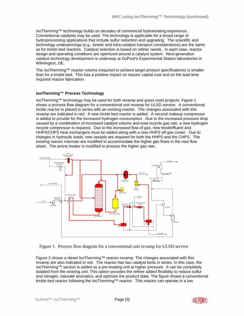
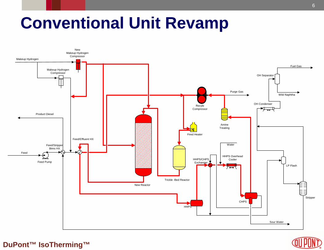
IsoTherming™ technology may be used for both revamp and grass roots projects. Figure 1 shows a process flow diagram for a conventional unit revamp for ULSD service. A conventional trickle reactor is placed in series with an existing reactor. The changes associated with this revamp are indicated in red. A new trickle bed reactor is added. A second makeup compressor is added to provide for the increased hydrogen consumption. Due to the increased pressure drop caused by a combination of increased catalyst volume and total recycle gas rate, a new hydrogen recycle compressor is required. Due to the increased flow of gas, new feed/effluent and HHPS/CHPS heat exchangers must be added along with a new HHPS off gas cooler. Due to changes in hydraulic loads, new vessels are required for both the HHPS and the CHPS. The existing reactor internals are modified to accommodate the higher gas flows in the new flow sheet. The amine treater is modified to process the higher gas rate.
Trickle -Bed Reactor
RecyleCompressor
New Reactor
Feed Pump
Feed/StripperBtms HX
Feed/Effluent HX
Fired Heater
OH Separator
OH Condenser
LP Flash
Stripper
Makeup HydrogenCompressor
Sour Water
Water
AmineTreating
Product Diesel
HHPS
CHPS
Feed
NewMakeup Hydrogen
Compressor
Fuel Gas
Wild Naphtha
HHPS/CHPSExchanger
HHPS OverheadCooler
Makeup Hydrogen
Purge Gas
Figure 1. Process flow diagram for a conventional unit revamp for ULSD service
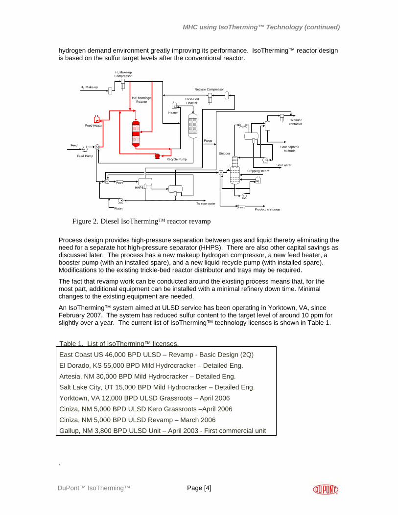
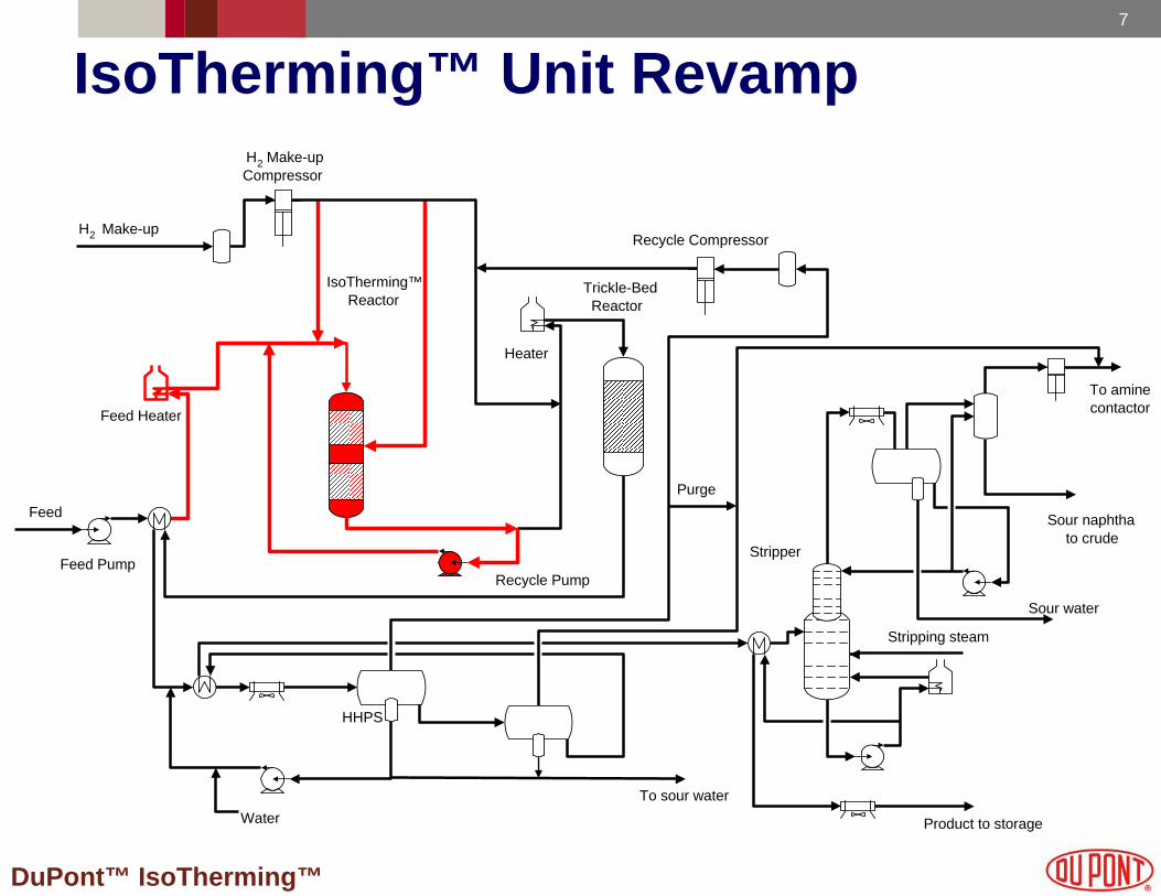
Figure 2 shows a diesel IsoTherming™ reactor revamp. The changes associated with this revamp are also indicated in red. The reactor has two catalyst beds in series. In this case, the IsoTherming™ section is added as a pre-treating unit at higher pressure. It can be completely isolated from the existing unit. This option provides the refiner added flexibility to reduce sulfur and nitrogen, saturate aromatics, and optimize the product slate. The figure shows a conventional trickle bed reactor following the IsoTherming™ reactor. This reactor can operate in a low
Page [3] DuPont™ IsoTherming™
MHC using IsoTherming™ Technology (continued)
hydrogen demand environment greatly improving its performance. IsoTherming™ reactor design is based on the sulfur target levels after the conventional reactor.
Feed Pump
Feed Heater
H2 Make-upCompressor
IsoTherming®Reactor
Recycle Pump
HHPS
Heater
Tricle-BedReactor
Recycle Compressor
Stripper
Feed
To sour waterWater
Stripping steam
Product to storage
To aminecontactor
Sour water
Sour naphthato crude
Purge
H2 Make-up
Figure 2. Diesel IsoTherming™ reactor revamp
Process design provides high-pressure separation between gas and liquid thereby eliminating the need for a separate hot high-pressure separator (HHPS). There are also other capital savings as discussed later. The process has a new makeup hydrogen compressor, a new feed heater, a booster pump (with an installed spare), and a new liquid recycle pump (with installed spare). Modifications to the existing trickle-bed reactor distributor and trays may be required.
The fact that revamp work can be conducted around the existing process means that, for the most part, additional equipment can be installed with a minimal refinery down time. Minimal changes to the existing equipment are needed.
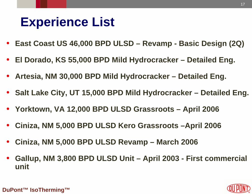
An IsoTherming™ system aimed at ULSD service has been operating in Yorktown, VA, since February 2007. The system has reduced sulfur content to the target level of around 10 ppm for slightly over a year. The current list of IsoTherming™ technology licenses is shown in Table 1.
Table 1. List of IsoTherming™ licenses.East Coast US 46,000 BPD ULSD – Revamp - Basic Design (2Q)El Dorado, KS 55,000 BPD Mild Hydrocracker – Detailed Eng.Artesia, NM 30,000 BPD Mild Hydrocracker – Detailed Eng.Salt Lake City, UT 15,000 BPD Mild Hydrocracker – Detailed Eng.Yorktown, VA 12,000 BPD ULSD Grassroots – April 2006Ciniza, NM 5,000 BPD ULSD Kero Grassroots –April 2006Ciniza, NM 5,000 BPD ULSD Revamp – March 2006Gallup, NM 3,800 BPD ULSD Unit – April 2003 - First commercial unit
.
Page [4] DuPont™ IsoTherming™

MHC using IsoTherming™ Technology (continued)
IsoTherming™ Process Technology for Mild Hydrocracking (MHC)
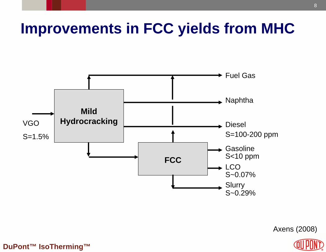
The benefits of hydrotreating Fluid Catalytic Cracking (FCC) unit feed are well known in the industry. Figure 3 illustrates a role for MHC in FCC feed pretreatment [2]. MHC reduces feed nitrogen and sulfur and provides conversion.
Mild
Hydrocracking
FCC
VGO
S=1.5%
Fuel Gas
Naphtha
DieselS=100-200 ppm
GasolineS<10 ppmLCOS~0.07%SlurryS~0.29%
Figure 3. Benefits of MHC in FCC feed pretreatment
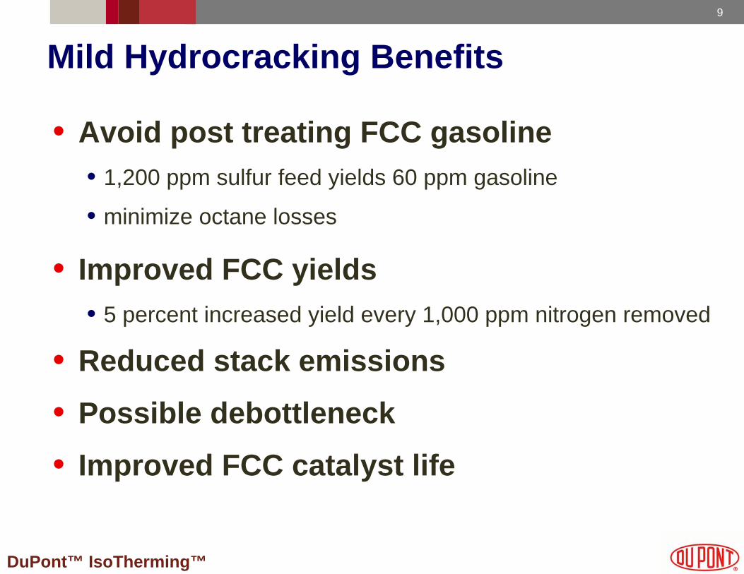
A reduction in sulfur content translates to lower sulfur levels in the FCC gasoline. For example, a 1,200 ppm sulfur concentration in the FCC feed translates to approximately 60 ppm sulfur content in FCC gasoline. Proper MHC process design may obviate the need for further hydrotreating to reduce fuel sulfur content and minimize octane losses associated with saturating olefins.
The lower basic nitrogen content of the pretreated feed increases catalytic cracking activity and improves FCC gasoline yield. A reduction in FCC feed metals content translates into improved life of the FCC catalyst. The MHC pre-treatment option provides the refiner with an opportunity to de-bottleneck the refinery. Heavier product from MHC may be sent to the FCC along with additional FCC feed, thereby increasing capacity. The lower sulfur content of the FCC feed translates to lower SOx emissions from the FCC regenerator.
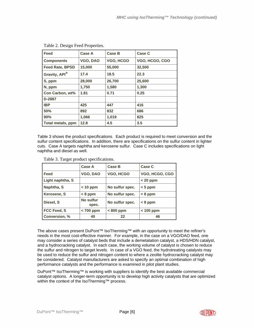
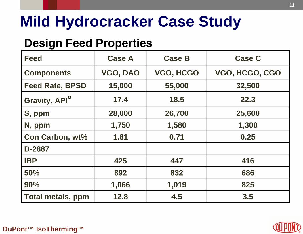
Table 2 presents three case studies of IsoTherming™ technology for MHC where the heavy product is sent to the FCC. The feed in Case A is a combination of Vacuum Gas Oil (VGO) and De-Asphalted Oil (DAO). Case B is a feed containing VGO and Heavy Coker Gas Oil (HCGO), while Case C has VGO, HCGO, and some Coker Gas Oil (CGO) blended in. In each case, the feed has around 2.5% sulfur, over 1,300 ppm of total nitrogen, 0.25 to 1.8% CCR, and 3 to 13 ppm metals.
Page [5] DuPont™ IsoTherming™
MHC using IsoTherming™ Technology (continued)
3.54.512.8Total metals, ppm8251,0191,06690%68683289250%416447425IBP
D-28870.250.711.81Con Carbon, wt%
1,58026,700
18.5
55,000VGO, HCGO
Case B
1,3001,750N, ppm25,60028,000S, ppm
22.317.4Gravity, API°32,50015,000Feed Rate, BPSDVGO, HCGO, CGOVGO, DAOComponents
Case CCase AFeed
Table 2. Design Feed Properties.
Table 3 shows the product specifications. Each product is required to meet conversion and the sulfur content specifications. In addition, there are specifications on the sulfur content in lighter cuts. Case A targets naphtha and kerosene sulfur. Case C includes specifications on light naphtha and diesel as well.
462240Conversion, %< 100 ppm< 800 ppm< 700 ppmFCC Feed, S
No sulfur spec.
No sulfur spec.
No sulfur spec.
VGO, HCGO
Case B
< 8 ppmNo sulfurspec.Diesel, S
< 8 ppm< 8 ppmKerosene, S
< 5 ppm< 10 ppmNaphtha, S
< 20 ppmLight naphtha, SVGO, HCGO, CGOVGO, DAOFeed
Case CCase A
Table 3. Target product specifications.
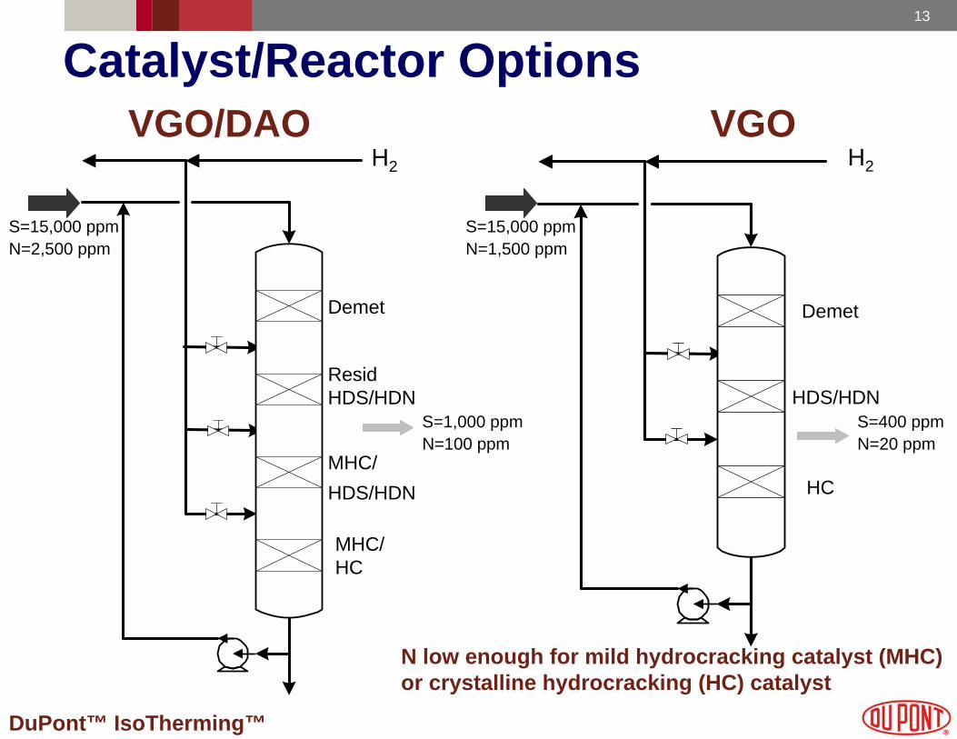
The above cases present DuPont™ IsoTherming™ with an opportunity to meet the refiner's needs in the most cost-effective manner. For example, in the case on a VGO/DAO feed, one may consider a series of catalyst beds that include a demetalation catalyst, a HDS/HDN catalyst, and a hydrocracking catalyst. In each case, the working volume of catalyst is chosen to reduce the sulfur and nitrogen to target levels. In case of a VGO feed, the hydrotreating catalysts may be used to reduce the sulfur and nitrogen content to where a zeolite hydrocracking catalyst may be considered. Catalyst manufacturers are asked to specify an optimal combination of high performance catalysts and the performance is examined in pilot plant studies.
DuPont™ IsoTherming™ is working with suppliers to identify the best available commercial catalyst options. A longer-term opportunity is to develop high activity catalysts that are optimized within the context of the IsoTherming™ process.
Page [6] DuPont™ IsoTherming™
MHC using IsoTherming™ Technology (continued)
Page [7]
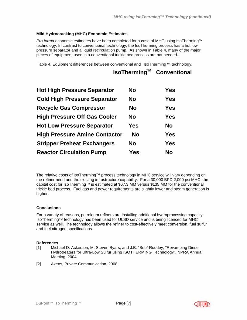
Mild Hydrocracking (MHC) Economic Estimates
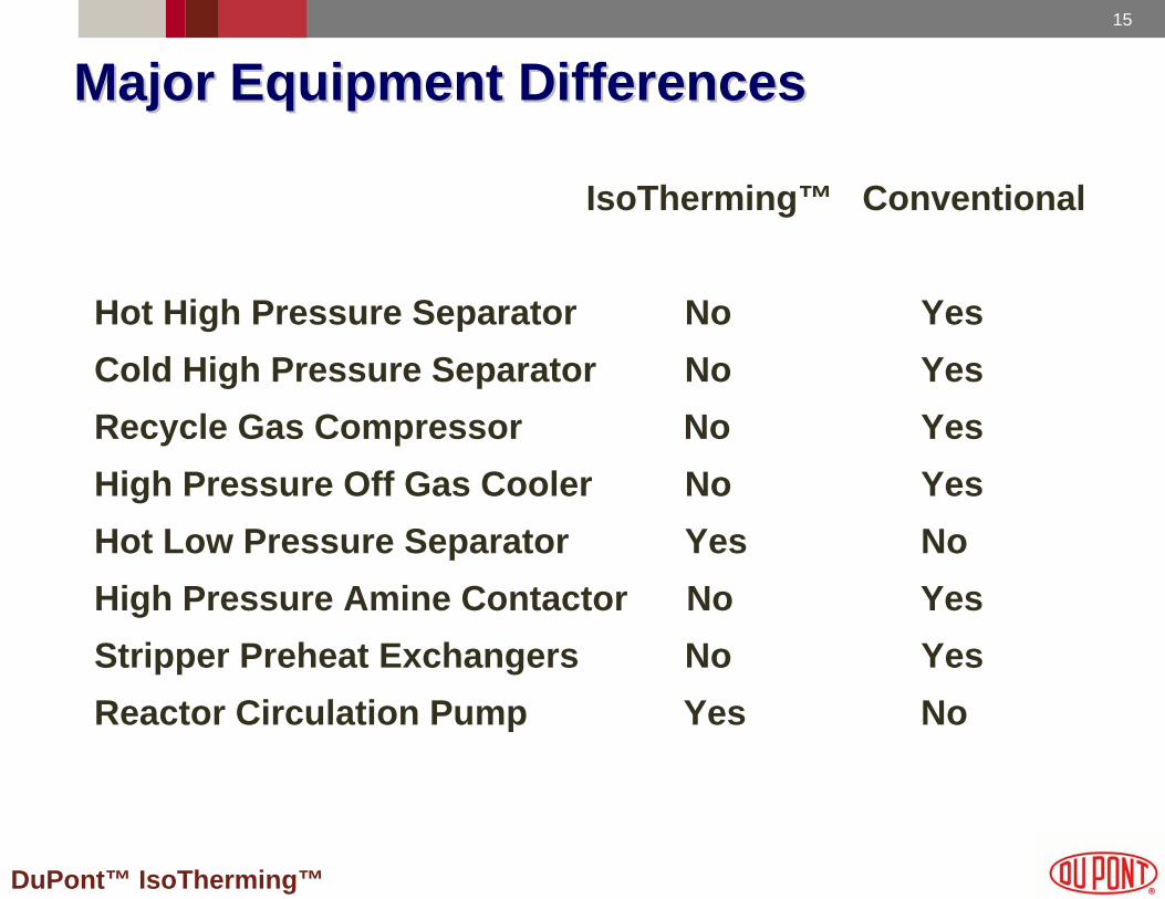
Pro forma economic estimates have been completed for a case of MHC using IsoTherming™ technology. In contrast to conventional technology, the IsoTherming process has a hot low pressure separator and a liquid recirculation pump. As shown in Table 4, many of the major pieces of equipment used in a conventional trickle bed process are not needed.
Table 4. Equipment differences between conventional and IsoTherming™ technology.
IsoThermingTM Conventional
Hot High Pressure Separator No YesCold High Pressure Separator No YesRecycle Gas Compressor No YesHigh Pressure Off Gas Cooler No YesHot Low Pressure Separator Yes NoHigh Pressure Amine Contactor No YesStripper Preheat Exchangers No YesReactor Circulation Pump Yes No
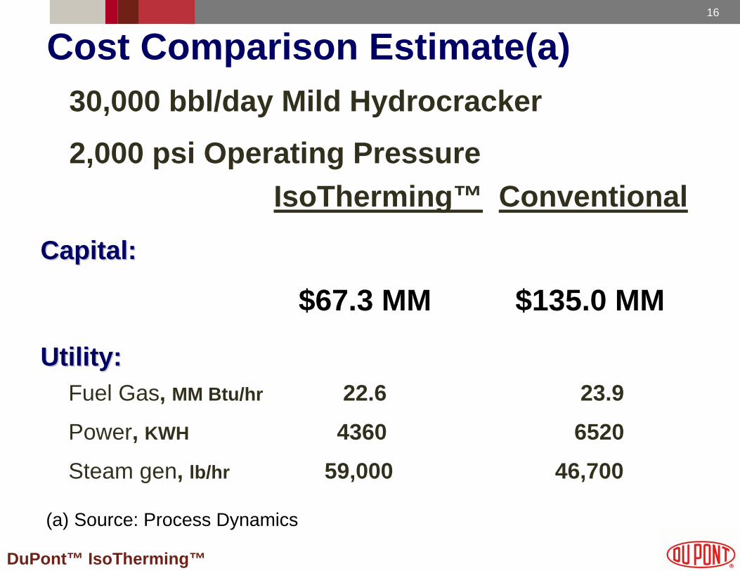
The relative costs of IsoTherming™ process technology in MHC service will vary depending on the refiner need and the existing infrastructure capability. For a 30,000 BPD 2,000 psi MHC, the capital cost for IsoTherming™ is estimated at $67.3 MM versus $135 MM for the conventional trickle bed process. Fuel gas and power requirements are slightly lower and steam generation is higher.
Conclusions
For a variety of reasons, petroleum refiners are installing additional hydroprocessing capacity. IsoTherming™ technology has been used for ULSD service and is being licenced for MHC service as well. The technology allows the refiner to cost-effectively meet conversion, fuel sulfur and fuel nitrogen specifications.
References [1] Michael D. Ackerson, M. Steven Byars, and J.B. “Bob” Roddey, "Revamping Diesel
Hydrotreaters for Ultra-Low Sulfur using ISOTHERMING Technology", NPRA Annual Meeting, 2004.
[2] Axens, Private Communication, 2008.
DuPont™ IsoTherming™
DuPont™ IsoTherming™
Carmo J. Pereira, Ph.D.DuPont Engineering Technology
Luis E. Murillo, Ph.D.Wayne B. ElyMichael J. Hennessy, Ph.D.DuPont Chemical Solutions Enterprise
Scott L. WebsterGlenn C. LioliosDuPontTM IsoTherming™ Clean Fuel Technologies
Michael D. Ackerson, Ph.D.M. Steven Byars, Ph.D.Process Dynamics, Inc.
Presented at the 2008 Annual Meeting of the NPRA, San Diego, CA
Mild Hydrocracking using IsoTherming™ Technology
2
DuPont™ IsoTherming™
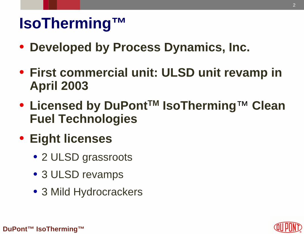
IsoTherming™• Developed by Process Dynamics, Inc.
• First commercial unit: ULSD unit revamp in April 2003
• Licensed by DuPontTM IsoTherming™ Clean Fuel Technologies
• Eight licenses• 2 ULSD grassroots • 3 ULSD revamps• 3 Mild Hydrocrackers
3
DuPont™ IsoTherming™
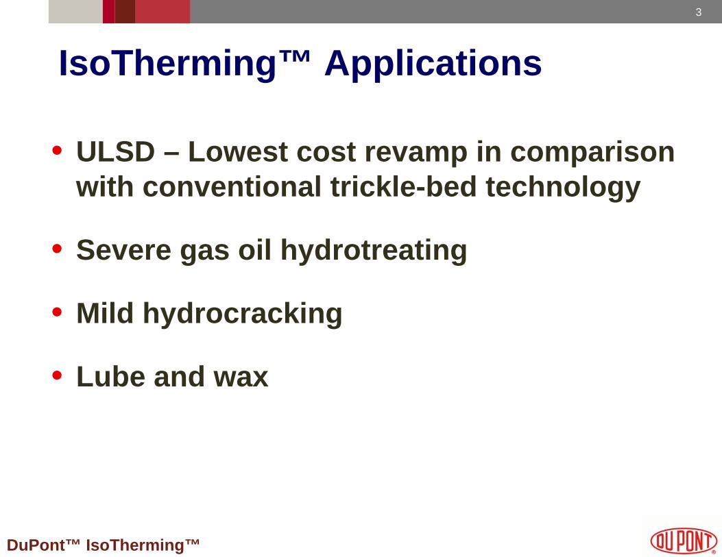
IsoTherming™ Applications
• ULSD – Lowest cost revamp in comparison with conventional trickle-bed technology
• Severe gas oil hydrotreating
• Mild hydrocracking
• Lube and wax
4
DuPont™ IsoTherming™
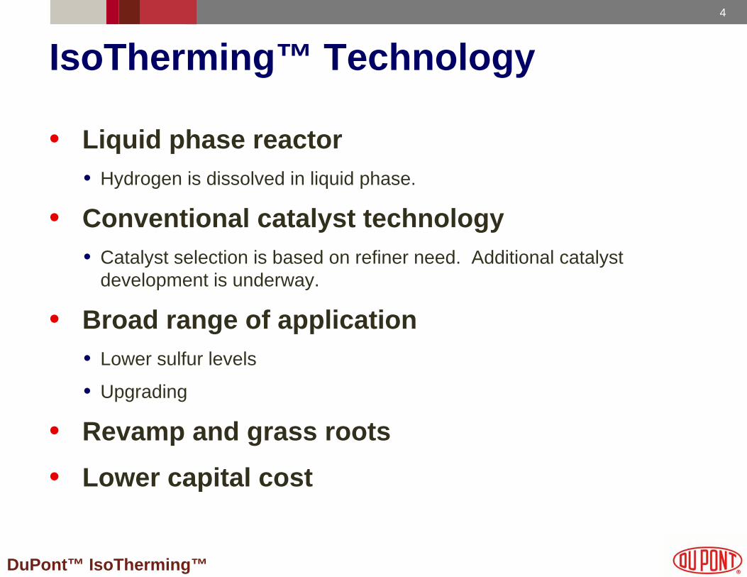
IsoTherming™ Technology
• Liquid phase reactor• Hydrogen is dissolved in liquid phase.
• Conventional catalyst technology• Catalyst selection is based on refiner need. Additional catalyst
development is underway.
• Broad range of application • Lower sulfur levels
• Upgrading
• Revamp and grass roots
• Lower capital cost
5
DuPont™ IsoTherming™
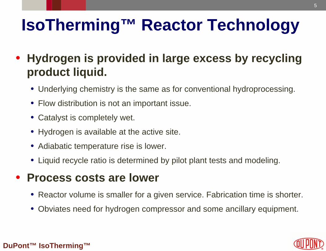
• Hydrogen is provided in large excess by recycling product liquid.• Underlying chemistry is the same as for conventional hydroprocessing.
• Flow distribution is not an important issue.
• Catalyst is completely wet.
• Hydrogen is available at the active site.
• Adiabatic temperature rise is lower.
• Liquid recycle ratio is determined by pilot plant tests and modeling.
• Process costs are lower• Reactor volume is smaller for a given service. Fabrication time is shorter.
• Obviates need for hydrogen compressor and some ancillary equipment.
IsoTherming™ Reactor Technology
6
DuPont™ IsoTherming™
Conventional Unit Revamp
Trickle -Bed Reactor
RecyleCompressor
New Reactor
Feed Pump
Feed/StripperBtms HX
Feed/Effluent HX
Fired Heater
OH Separator
OH Condenser
LP Flash
Stripper
Makeup HydrogenCompressor
Sour Water
Water
AmineTreating
Product Diesel
HHPS
CHPS
Feed
NewMakeup Hydrogen
Compressor
Fuel Gas
Wild Naphtha
HHPS/CHPSExchanger
HHPS OverheadCooler
Makeup Hydrogen
Purge Gas
7
DuPont™ IsoTherming™
IsoTherming™ Unit Revamp
Feed Pump
Feed Heater
H2 Make-upCompressor
IsoTherming™Reactor
Recycle Pump
HHPS
Heater
Trickle-BedReactor
Recycle Compressor
Stripper
Feed
To sour waterWater
Stripping steam
Product to storage
To aminecontactor
Sour water
Sour naphthato crude
Purge
H2 Make-up
8
DuPont™ IsoTherming™
Improvements in FCC yields from MHC
Mild Hydrocracking
FCC
VGO
S=1.5%
Fuel Gas
Naphtha
DieselS=100-200 ppm
GasolineS<10 ppmLCOS~0.07%SlurryS~0.29%
Axens (2008)
9
DuPont™ IsoTherming™
Mild Hydrocracking Benefits
• Avoid post treating FCC gasoline• 1,200 ppm sulfur feed yields 60 ppm gasoline
• minimize octane losses
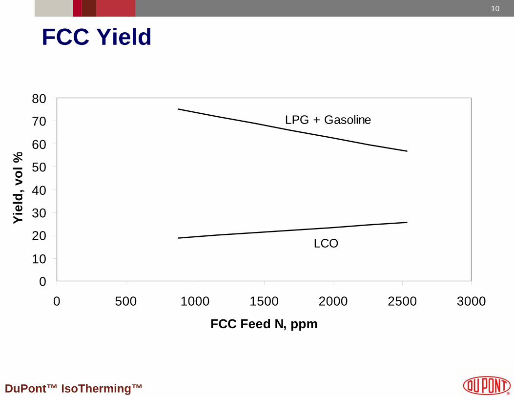
• Improved FCC yields• 5 percent increased yield every 1,000 ppm nitrogen removed
• Reduced stack emissions
• Possible debottleneck
• Improved FCC catalyst life
10
DuPont™ IsoTherming™
FCC Yield
0
10
20
30
40
50
60
70
80
0 500 1000 1500 2000 2500 3000
FCC Feed N, ppm
Yiel
d, v
ol %
LPG + Gasoline
LCO
11
DuPont™ IsoTherming™
Mild Hydrocracker Case Study
Feed Case A Case B Case C
Components VGO, DAO VGO, HCGO VGO, HCGO, CGOFeed Rate, BPSD 15,000 55,000 32,500
Gravity, API° 17.4 18.5 22.3
S, ppm 28,000 26,700 25,600N, ppm 1,750 1,580 1,300Con Carbon, wt% 1.81 0.71 0.25D-2887IBP 425 447 41650% 892 832 68690% 1,066 1,019 825Total metals, ppm 12.8 4.5 3.5
Design Feed Properties

12
DuPont™ IsoTherming™
Mild Hydrocracker Case Study
Case A Case B Case C
Feed VGO, DAO VGO, HCGO VGO, HCGO, CGOLight naphtha, S < 20 ppm
Naphtha, S < 10 ppm No sulfur spec. < 5 ppm
Kerosene, S < 8 ppm No sulfur spec. < 8 ppm
Diesel, S No sulfur spec. No sulfur spec. < 8 ppm
FCC Feed, S < 700 ppm < 800 ppm < 100 ppmConversion, % 40 22 46
Design Products
13
DuPont™ IsoTherming™
VGO/DAO VGOH2
Demet
ResidHDS/HDN
MHC/HDS/HDN
MHC/HC
S=15,000 ppmN=2,500 ppm
S=1,000 ppmN=100 ppm
S=15,000 ppmN=1,500 ppm
Demet
HDS/HDN
HC
S=400 ppmN=20 ppm
H2
Catalyst/Reactor Options
N low enough for mild hydrocracking catalyst (MHC) or crystalline hydrocracking (HC) catalyst
14
DuPont™ IsoTherming™
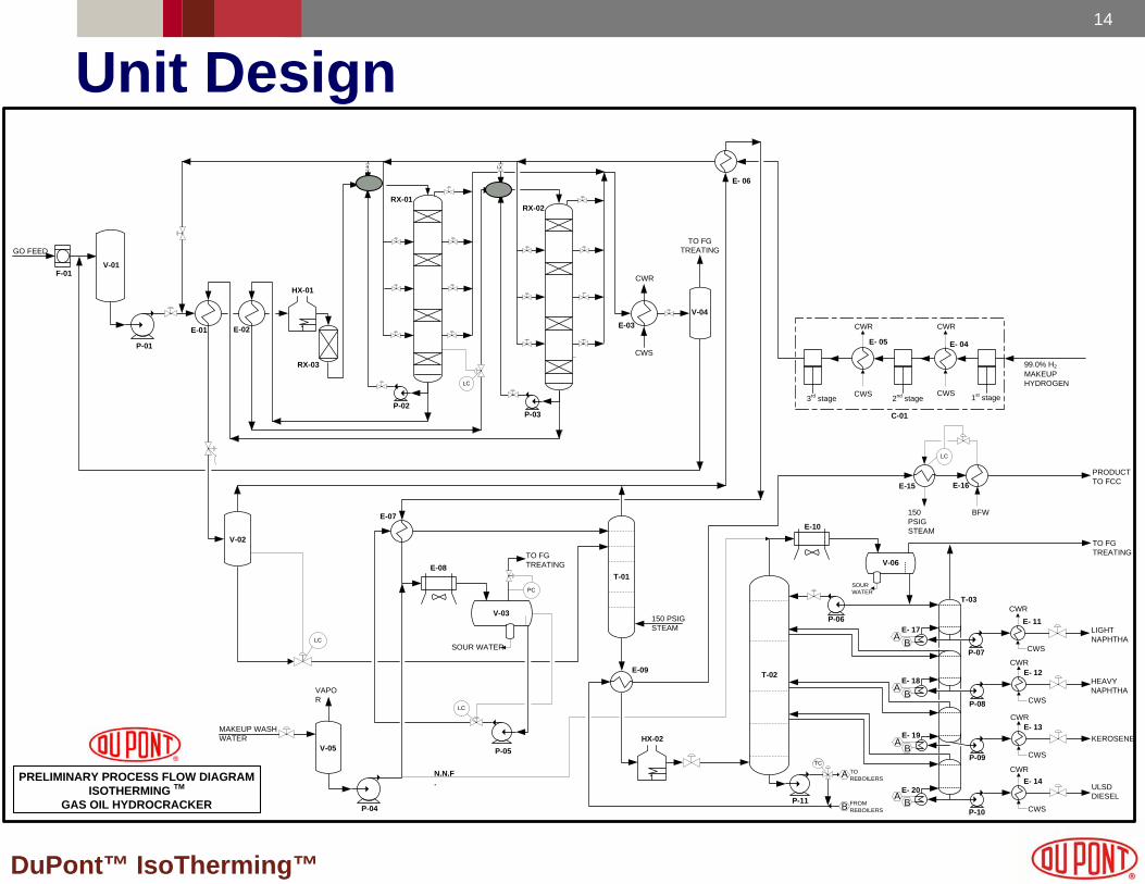
Unit Design
CWS
E- 14
P-10
CWS
E- 13
P-09
CWS
E- 12CWR
P-08
HEAVY NAPHTHA
E- 11
CWS
CWR
P-03
SOUR WATER
MAKEUP WASH WATER
E-08
V-03
GO FEED
V-01
P-01
E-01
HX-01
P-02
E-03
MAKEUP HYDROGEN
99.0% H2
E- 04
C-01
150 PSIGSTEAM
T-01
PRELIMINARY PROCESS FLOW DIAGRAMISOTHERMING TM
GAS OIL HYDROCRACKER
E-15
150 PSIGSTEAM
BFW
V-02
1st stage2nd stage
RX-03
CWS
CWR
CWS
CWR
V-04
E-16
E- 06
TO FGTREATING
TO FGTREATING
V-05
P-04
VAPOR
F-01
LC
LC
LC
E- 05
CWS
CWR
3rd stage
PC
LC
M-01
HX-02
E-09 T-02
P-11
E-10
V-06
P-06
SOUR WATER
P-05
E-07
N.N.F.
LC
M-02
RX-01
RX-02
TO FGTREATING
TC
P-07
LIGHTNAPHTHA
KEROSENE
ULSDDIESEL
CWR
PRODUCTTO FCC
CWR
RX-01
E-02
A
A
B
B
AB
AB
A
B
E- 17
TOREBOILERS
FROMREBOILERS
T-03
E- 18
E- 19
E- 20
15
DuPont™ IsoTherming™
Major Equipment DifferencesMajor Equipment Differences
IsoTherming™ Conventional
Hot High Pressure Separator No YesCold High Pressure Separator No YesRecycle Gas Compressor No YesHigh Pressure Off Gas Cooler No YesHot Low Pressure Separator Yes NoHigh Pressure Amine Contactor No YesStripper Preheat Exchangers No YesReactor Circulation Pump Yes No
16
DuPont™ IsoTherming™
Cost Comparison Estimate(a)
Capital:Capital:
IsoTherming™ Conventional
$67.3 MM $135.0 MM
30,000 bbl/day Mild Hydrocracker
2,000 psi Operating Pressure
Fuel Gas, MM Btu/hr 22.6 23.9
Power, KWH 4360 6520
Steam gen, lb/hr 59,000 46,700
Utility:Utility:
(a) Source: Process Dynamics
17
DuPont™ IsoTherming™
Experience List• East Coast US 46,000 BPD ULSD – Revamp - Basic Design (2Q)
• El Dorado, KS 55,000 BPD Mild Hydrocracker – Detailed Eng.
• Artesia, NM 30,000 BPD Mild Hydrocracker – Detailed Eng.
• Salt Lake City, UT 15,000 BPD Mild Hydrocracker – Detailed Eng.
• Yorktown, VA 12,000 BPD ULSD Grassroots – April 2006
• Ciniza, NM 5,000 BPD ULSD Kero Grassroots –April 2006
• Ciniza, NM 5,000 BPD ULSD Revamp – March 2006
• Gallup, NM 3,800 BPD ULSD Unit – April 2003 - First commercial unit

18
DuPont™ IsoTherming™
Summary
• Mild hydrocracking may be effectively used for upgrading, e.g., pre-treating FCC feed.
• IsoTherming™ technology may be designed or retrofitted for ULSD and mild hydrocracking service.
• The technology allows the refiner to simultaneously meet conversion, fuel sulfur and fuel nitrogen specifications.
• Capital and operating costs are lower than conventional hydroprocessing technology.
19
DuPont™ IsoTherming™