Embed Size (px)
Citation preview
MikroTik™ V2.0 Router SoftwareTechnical Reference Manual
Manual’s Revision 2000-05-05
© Mikrotikls SIA 1999

Page 2 of 72
Mikrotikls SIA
No part of this document may be reproduced or transmitted in any means, electronic or mechanical, forany purpose, without the written permission of Mikrotikls. Information in this document is subject tochange without notice. Mikrotikls makes no representation or warranties with respect to the contents ofthis manual and specifically disclaims any express or implied warranties of merchantability or fitness forany particular purpose.
© 1999 Mikrotikls SIA.All rights reserved.
Printed in Latvia
MikroTik™ and Mikrotikls are trademarks of Mikrotikls SIA, Riga, Latvia.
Other trademarks used are properties of their respective owners.
Portions of this software may fall under the following copyrights:Copyright © 1991 D.L.S. AssociatesGateDaemon - Copyright © 1995, 1996, 1997, 1998 The Regents of the University of Michigan. Allrights reserved. GateDaemon was originated and developed through release 3.0 by Cornell Universityand its collaborators.Id.so - Copyright © 1988 Regents of the University of California. All rights reserved. Id.so software wasdeveloped by the University of California, Berkeleycmu snmp - Copyright © 1988, 1989, by Carnegie Mellon University. All rights reserved. Permission touse, copy, modify and distribute this software and its documentation for any perpose and without fee isgranted, provided that the above copyright notice appear in all copies and that copyright notice and thispermission notice appear in the supporting documentation.PPP - Copyright © 1993 The Australian National Universitynetkit, telnet - Copyright © 1983, 1991 The Regents of the University of California. This product includessoftware developed by the University of California, Berkeley and its contributors. This software isprovided by the regents and contributors “as is” and any express or implied warranties, including, but notlimited to, the implied warranties of merchantability and fitness for a particular purpose are disclaimed.bash, boa, dialog, e2fsprogs, fileutils, getty_ps, gzip, modutils, mount, net-tools, procps, shellutils,sysklogd, sysvinit, tar, textutils, updated, util-linux - For the above GPL licensed programs in accordancewith the GPL license, Mikrotikls offers to organize a copy of the source code or it can be found on moststandard Linux distributions. Write [email protected] for more information.glibc, libstdc++, ncurses, termcap - For the above LGPL licensed programs in accordance with theLGPL license, Mikrotikls offers to organize a copy of the source code or it can be found on moststandard Linux distributions. Write [email protected] for more information.

Page 3 of 72
TABLE OF CONTENTS
PREFACE............................................................................................................................ 7
DOCUMENT ORGANIZATION ................................................................................................7DOCUMENT CONVENTIONS ..................................................................................................7
1. STARTUP GUIDE ........................................................................................................ 8
1-1 BEFORE YOU START ...............................................................................................81-2 HARDWARE REQUIREMENTS AND BIOS SETTINGS .................................................81-3 INSTALLING THE SOFTWARE ...................................................................................91-4 CONFIGURING THE ROUTER..................................................................................10
2 USER INTERCONNECTION DESCRIPTION ......................................................... 12
2.1 JAVA INTERCONNECTION DESCRIPTION ................................................................122.1-1 GENERAL INFORMATION ....................................................................................122.1-2 HOW TO ............................................................................................................122.2 CONSOLE INTERCONNECTION DESCRIPTION.........................................................142.2-1 HOW TO ............................................................................................................152.2-2 IMPORT AND EXPORT.........................................................................................16
3 DEVICE DRIVER MANAGEMENT.......................................................................... 17
3-1 MANAGING DEVICE DRIVERS FROM JAVA.............................................................173-2 MANAGING DEVICE DRIVERS FROM CONSOLE......................................................173-3 DEVICE DRIVER PARAMETERS..............................................................................173-4 SUPPORTED INTERFACES.......................................................................................18
4 NETWORK INTERFACE MANAGEMENT ............................................................. 21
4.1 INTRODUCTION.......................................................................................................214.1-1 MANAGING NETWORK INTERFACES FROM JAVA ................................................214.1-2 MANAGING NETWORK INTERFACES FROM CONSOLE..........................................214.1-3 BASIC INTERFACE PARAMETER DESCRIPTION ....................................................224.2 ETHERNET INTERFACES .........................................................................................224.2-1 MANAGING ETHERNET INTERFACES FROM JAVA ................................................224.2-2 MANAGING ETHERNET INTERFACES FROM CONSOLE .........................................224.3 ARLAN IC2200 INTERFACES ..................................................................................234.3-1 MANAGING ARLAN IC2200 INTERFACES FROM JAVA .........................................234.3-2 MANAGING ARLAN IC2200 INTERFACES FROM CONSOLE ..................................234.3-3 ARLAN IC2200 PARAMETER DESCRIPTION.........................................................234.4 LMC SYNC INTERFACES ........................................................................................244.4-1 MANAGING LMC SYNC INTERFACES FROM JAVA...............................................244.4-2 MANAGING LMC SYNC INTERFACES FROM CONSOLE ........................................244.4-3 LMC SYNC INTERFACE PARAMETER DESCRIPTION ............................................244.5 PPP INTERFACES....................................................................................................25

Page 4 of 72
4.5-1 MANAGING PPP INTERFACES FROM JAVA ..........................................................254.5-2 MANAGING PPP INTERFACES FROM CONSOLE ...................................................254.5-3 PPP INTERFACE PARAMETERS ...........................................................................264.6 IPSEC TUNNELS......................................................................................................264.6-1 MANAGING IPSEC TUNNELS FROM JAVA ...........................................................264.6-2 MANAGING IPSEC TUNNELS FROM CONSOLE.....................................................274.6-3 IPSEC TUNNEL PARAMETERS.............................................................................274.7 RADIOLAN INTERFACES........................................................................................284.7-1 MANAGING RADIOLAN INTERFACES FROM JAVA ..............................................284.7-2 MANAGING RADIOLAN INTERFACES FROM CONSOLE .......................................284.7-3 RADIOLAN INTERFACE PARAMETERS ...............................................................294.8 MOXA SYNC INTERFACES.......................................................................................294.8-1 MANAGING MOXA SYNC INTERFACES FROM JAVA .............................................294.8-2 MANAGING MOXA SYNC INTERFACES FROM CONSOLE ......................................294.8-3 MOXA SYNC INTERFACE PARAMETERS ..............................................................304.9 AIRONET 35/45/4800 INTERFACES .........................................................................304.9-1 MANAGING AIRONET 35/45/4800 INTERFACES FROM JAVA ................................314.9-2 MANAGING AIRONET 35/45/4800 INTERFACES FROM CONSOLE .........................314.9-3 AIRONET 35/45/4800 INTERFACE PARAMETERS .................................................324.10 WAVELAN INTERFACES BASE CONFIGURATION.................................................324.10-1 MANAGING WAVELAN INTERFACES FROM CONSOLE ......................................334.10-2 WAVELAN INTERFACE PARAMETERS ..............................................................33
5 BRIDGE CONFIGURATION ..................................................................................... 34
5-1 CONFIGURING BRIDGE FROM JAVA .......................................................................345-2 CONFIGURING BRIDGE FROM CONSOLE ................................................................345-3 BRIDGE CONFIGURATION PARAMETERS................................................................34
6 INTERNET PROTOCOL MANAGEMENT .............................................................. 35
6.1 ADDRESSES .............................................................................................................356.1-1 MANAGING ADDRESSES FROM JAVA ..................................................................356.1-2 MANAGING ADDRESSES FROM CONSOLE ...........................................................356.1-3 GENERAL ADDRESS PARAMETERS .....................................................................366.2 ROUTES...................................................................................................................366.2-1 MANAGING ROUTES FROM JAVA........................................................................366.2-2 MANAGING ROUTES FROM CONSOLE .................................................................366.2-3 GENERAL ROUTES PARAMETERS .......................................................................376.3 ARP ........................................................................................................................376.3-1 MANAGING ARP FROM JAVA .............................................................................376.3-2 MANAGING ARP FROM CONSOLE ......................................................................376.3-3 GENERAL ARP PARAMETERS ............................................................................386.4 PPP .........................................................................................................................386.4-1 MANAGING PPP FROM JAVA ..............................................................................386.4-2 MANAGING PPP FROM CONSOLE .......................................................................386.4-3 GENERAL PPP PARAMETERS..............................................................................396.5 DHCP .....................................................................................................................396.5-1 MANAGING DHCP FROM JAVA ..........................................................................406.5-2 MANAGING DHCP FROM CONSOLE ...................................................................406.5-3 GENERAL DHCP PARAMETERS..........................................................................406.6 FIREWALL...............................................................................................................416.6-1 MANAGING FIREWALL FUNCTIONS FROM JAVA..................................................426.6-2 MANAGING FIREWALL FUNCTIONS FROM CONSOLE ...........................................42

Page 5 of 72
6.6-3 GENERAL FIREWALL PARAMETERS ....................................................................436.7 NAT ........................................................................................................................446.7-1 MANAGING NAT FROM JAVA ............................................................................446.7-2 MANAGING NAT FROM CONSOLE......................................................................456.7-3 GENERAL NAT PARAMETERS ............................................................................456.8 DNS ........................................................................................................................466.8-1 MANAGING DNS FROM JAVA.............................................................................466.8-2 MANAGING DNS FROM CONSOLE ......................................................................466.8-3 GENERAL DNS PARAMETERS ............................................................................47
7 SNMP SERVICE CONFIGURATION ....................................................................... 48
7-1 CONFIGURING SNMP FROM JAVA.........................................................................487-2 CONFIGURING SNMP FROM CONSOLE..................................................................487-3 SNMP CONFIGURATION PARAMETERS .................................................................48
8 QUEUES MANAGEMENT ......................................................................................... 49
8-1 MANAGING QUEUING FROM JAVA ........................................................................498-2 MANAGING QUEUING FROM CONSOLE..................................................................498-3 GENERAL QUEUING PARAMETERS ........................................................................49
9 ADVANCED ROUTING MANAGEMENT ............................................................... 52
9.1 ROUTING INFORMATION PROTOCOL .....................................................................529.1-1 MANAGING RIP FROM JAVA ..............................................................................529.1-2 MANAGING RIP FROM CONSOLE........................................................................529.1-3 GENERAL RIP PARAMETERS ..............................................................................539.2 OPEN SHORTEST PATH FIRST.................................................................................539.2-1 MANAGING OSPF FROM JAVA ...........................................................................539.2-2 MANAGING OSPF FROM CONSOLE ....................................................................539.2-3 GENERAL OSPF PARAMETERS...........................................................................55
10 SYSTEM CONFIGURATION .................................................................................. 57
10.1 TERMINAL SETUP AND BASIC SYSTEM SETUP......................................................5710.1-1 BASIC SYSTEM SETUP ......................................................................................5710.1-2 BASIC ROUTER SETUP......................................................................................5710.1-3 SET TERMINAL TYPE........................................................................................5810.2 PACKAGES.............................................................................................................5810.2-1 VIEWING PACKAGES FROM JAVA......................................................................5810.2-2 VIEWING PACKAGES FROM CONSOLE ...............................................................5910.2-3 PACKAGES PARAMETERS .................................................................................5910.3 SYSTEM HISTORY .................................................................................................6010.3-1 VIEWING SYSTEM HISTORY FROM JAVA ...........................................................6010.3-2 VIEWING SYSTEM HISTORY FROM CONSOLE ....................................................6010.3-3 SYSTEM HISTORY PARAMETERS.......................................................................6010.4 USER MANAGEMENT ............................................................................................6010.4-1 USER MANAGEMENT FROM JAVA .....................................................................6010.4-2 USER MANAGEMENT FROM CONSOLE ..............................................................6110.4-3 USER PARAMETERS..........................................................................................6110.5 CHANGE PASSWORD .............................................................................................62
Page 6 of 72
10.5-1 HOW TO CHANGE PASSWORD USING JAVA ......................................................6210.5-2 HOW TO CHANGE PASSWORD USING CONSOLE ................................................6210.6 SYSTEM RESOURCES.............................................................................................6310.6-1 VIEWING SYSTEM RESOURCES FROM JAVA ......................................................6310.6-2 VIEWING SYSTEM RESOURCES FROM CONSOLE................................................6310.6-3 SYSTEM RESOURCES PARAMETERS ..................................................................6310.7 SYSTEM SHUTDOWN .............................................................................................6410.7-1 SYSTEM SHUTDOWN FROM JAVA......................................................................6410.7-2 SYSTEM SHUTDOWN FROM CONSOLE ...............................................................6410.8 SYSTEM IDENTITY.................................................................................................6510.8-1 SETTING SYSTEM IDENTITY FROM JAVA ...........................................................6510.8-2 SETTING SYSTEM IDENTITY FROM CONSOLE ....................................................6510.8-3 SYSTEM IDENTITY PARAMETERS ......................................................................6510.9 SYSTEM DATE AND TIME ......................................................................................6510.9-1 SETTING DATE AND TIME FROM JAVA ..............................................................6510.9-2 SETTING DATE AND TIME FROM CONSOLE .......................................................6510.9-3 DATE AND TIME PARAMETERS .........................................................................6610.10 SYSTEM LOGS MANAGEMENT ............................................................................6610.10-1 MANAGING SYSTEM LOGS FROM JAVA ...........................................................6610.10-2 MANAGING SYSTEM LOGS FROM CONSOLE ....................................................6610.10-3 SYSTEM LOGS PARAMETERS ..........................................................................6710.11 LICENSE ..............................................................................................................68
11 TOOLS ....................................................................................................................... 69
11.1 PING ......................................................................................................................6911.1-1 LAUNCHING PING UTILITY FROM JAVA ............................................................6911.1-2 LAUNCHING PING UTILITY FROM CONSOLE......................................................6911.1-3 PING UTILITY PARAMETER DESCRIPTION .........................................................6911.2 TRACEROUTE........................................................................................................7011.2-1 LAUNCHING TRACEROUTE UTILITY FROM JAVA ...............................................7011.2-2 LAUNCHING TRACEROUTE UTILITY FROM CONSOLE ........................................7011.2-3 GENERAL TRACEROUTE UTILITY PARAMETERS................................................7011.3 BANDWIDTH TEST.................................................................................................7011.3-1 TEST BANDWIDTH FROM JAVA .........................................................................7111.3-2 TEST BANDWIDTH FROM CONSOLE ..................................................................7111.3-3 BANDWIDTH TEST PARAMETERS......................................................................7111.4 PING FLOOD..........................................................................................................7211.4-1 LAUNCHING PING FLOOD FROM JAVA ..............................................................7211.4-2 LAUNCHING PING FLOOD FROM CONSOLE........................................................7211.4-3 PING FLOOD UTILITY PARAMETERS: ................................................................72

Page 7 of 72
Preface
Document Organization
The document consists of 11 main parts. Parts can be divided further intosections. Each section (or a part if it doesn’t consist of sections) of thisdocument is divided into three subsections. In the first subsectionmanagement from the Java Console is described. Management from theConsole is described in the second subsection. The third subsection isdevoted to description of the parameters. However some sections are notdivided if it is not necessary.
Document Conventions
In this publication, the following conventions are used:
§ All console related settings: commands, arguments, parameters, examplesand keywords are marked out with the Courier New font;
§ The following conventions are used in the command syntax description:
- In the place where something is written in between of “<” and “>”you need to enter a value, e.g. <address>;
- Optional parameters are enclosed in brackets, e.g.[interface <name>];
- The vertical line “I” means “OR”;

Page 8 of 72
1. Startup Guide
1-1 Before You Start
To make a PC based router running MikroTik™ Router Software, it isnecessary to:• Prepare the PC hardware to be dedicated router – no other programs can
be held on the HDD or run on the PC except the MikroTik™ RouterSoftware
• Prepare to obtain an installation archive from “Mikrotikls” SIA – the file isapproximately 5.5MB
• Prepare four 3.5” 1.44 MB blank, formatted floppy disks. Make sure thatthey are not write – protected or damaged. Disks will be used to make fourinstallation floppy disks from the installation archive for installing the PCrouter software.
After the preparations have been done• Download the installation archive from www.mikrotik.com. The standard
MikroTik™ Router Software installation is distributed as self – extractingarchive.
• Run the archive file on a Win95/98/NT computer, and press the ‘Setup’button to automatically launch the “MikroTik™ Disk Maker”. Follow thescreen instructions to create four installation floppy disks. Insert the disksin the FDD as prompted. Put a label on each disk to avoid later confusion.When the “MT Disk Maker” ends its work, you will have a set of MikroTik™Router Software installation disks ready.
• Install the MikroTik™ Router Software using the four installation floppydisks as described below.
• Obtain the license for your installation of the MikroTik™ Router Software.
1-2 Hardware Requirements and BIOS Settings
The MikroTik™ Router Software installs on a standard PC system with a harddisk or flash disk. Hardware requirements are as follows:
Processor – DX486 or higher CPU with math co-proccessor. Pentium (AMD,Cyrix, IDT WinChip or Intel) 100 or higher suggested;RAM – at least 16 MB;Video – Color or Monochrome VGA video card or on-board VGA port;HDD controller – IDE hard drive controller;HDD – Hard disk or flash disk (20 MB or more);FDD – 1,44 MB Floppy Drive. This is not needed after installation, and can be safelyremoved;Keyboard – may be also removed after the software installation, if BIOSallows the PC to boot without a keyboard.
Page 9 of 72
Monitor – may be removed after installation. You should keep the keyboardand monitor attached if you want to administer the system locally from theconsole.Network Interface – NE2000 or compatible NIC. For more supported networkcards and devices, please see ‘Supported Hardware’ section.
Check the BIOS settings of your router. Make sure that the boot sequence is‘A: C:’, and ‘Floppy drive seek at boot’ is enabled.
Check that the BIOS settings for PNP OS are disabled and PCI and ISAallocation of IRQs correspond to your interface installation plans. Disable theparalell port to free resources. Check the IO and IRQ assignments for SerialInterfaces, which should be as follows:
COM1 – IO 0x3f8 and IRQ 4COM2 – IO 0x2f8 and IRQ 3
If you use 20MB SanDisk 3.5” FlashDrive as the target HDD for your routerinstallation, use the recommended BIOS settings for it:
Cylinders 612, Heads 2, Sectors 32, Mode NORMAL
1-3 Installing the software
Put ‘Disk #1’ in the floppy drive, and boot up your router. The installation willbe looking for hard drives. You will see something like this:
Found harddrive on IDE primary master (disk C)To install software properly, it needs to be reformatted.
Format it? [y/n]:
Press yes to format you HDD.
Note that the primary hard disk of your router will be overwritten, and anyexisting data on it will be destroyed.
You will be asked to insert all next three installation floppies:
Please insert 2nd installation floppy.Press ENTER when ready
and so on until the last floppy drive will be inserted and you will be asked toreboot your computer:Software installed.Press ENTER to reboot
Remove the installation disk from the floppy disk drive and press ENTER.
Page 10 of 72
While booting up the router for the first time you will see your software ID, andyou will be asked to enter your software key. This key is unique depending onseveral variables including the particular data carrier (flash disk or hard drive)and information from your MikroTik registered account. Please enter thesoftware key obtained from MikroTik – www.mikrotik.com.
The software installation is complete.
Log on to your PC router running MikroTik™ Router Software for the first timeusing login name ‘root’ and password ‘root’. Please change the root’spassword later for security reasons to avoid unauthorized access to yourrouter.NOTE: There is no way to replace a lost password, so be careful!
1-4 Configuring the Router
A connection via console port is established using an RS-232 null modemcable. Standard PCs have a 9 pin male serial port built-in. Use any VT100terminal emulation program on your PC or Laptop. The requiredcommunication settings are:
9600 bps, 8 bit, No parity, 1 stop bit
For PC with Windows running, set the COM port to your corresponding serialport. Usually it is COM2.
After logging on to your PC router, you should go to the “ interface”submenu to see the installed interfaces. Use the following command for that:
interface> print
If the device driver for the installed network interface card is loadedautomatically (for example, most PCI NIC’s), the interface should already belisted. Select the desired interface and type and enable it:
interface>set up <interface name>
If the device driver could not be loaded automatically, load the driver for theinstalled NIC using the “driver” submenu. Use the load command andsupply the required parameters. For example, a NE2000 ISA card configuredto use IO 0x300 and IRQ 5 requires following line to be entered:
driver>load name ne2k-isa io 0x300
Do not forget to enable the interface from the “interface” submenu asdescribed above!
Go to the “ip address” submenu to assign an IP address to the router, forexample:

Page 11 of 72
ip address>add local 192.168.0.2 mask 255.255.255.224interface ether1
(If not supplied, the network prefix 192.168.0.0 and broadcast address192.168.0.31 will be calculated automatically in this case.)
Last thing to configure, before the router can be accessed remotely, is defaultgateway. Go to the ‘Routes’ menu and enter
ip route>add gateway 192.168.0.1 interface ether1
This will add the default route, i.e., to the destination 0.0.0.0 with networkmask 0.0.0.0, using host 192.168.0.1 as a gateway, which can be reachedusing interface ether1.
Try to ping some host on your network to test the initial configuration, forexample:
ip route>/ping 192.168.0.1
If you get responses from the host, your network connection works properly,andyou should be able to access the router remotely via network.
Please read appropriate sections of this manual for more detailed descriptionof configuration options.
Page 12 of 72
2 User Interconnection Description
2.1 Java Interconnection Description
MikroTik Java Console requires Java 2 browser plug-in.
In the Web Browser open the page with the addresshttp://<IPAddressOfTheRouter>. Then start the applet.
2.1-1 General Information
When you type your login name and password you are logged in the routervia Java Console.
All operations are performed via the main menu that is situated on the left ofthe main window. It consists of ten items. If menu item has an arrow sign thanit contains submenu. Each of them is described in the User Manual in thecorresponding chapter, excluding “Help”. The table below describes thecorrelation.
Menu item Chapter NameInterfaces Network Interface ManagementIP Internet Protocol ManagementRouting Advanced Routing ManagementQueues Queues ManagementBridge Bridge ConfigurationDrivers Device Driver ManagementSNMP SNMP Service ConfigurationSystem System ConfigurationTools ToolsPassword System Configuration
2.1-2 How To
Here are the most common actions that you perform on the entries:
Action DescriptionOpen To open the required window simply click on the corresponding
menu item.Add To add a new entry you should click on the “+” icon in the
corresponding window.Remove To remove an existing entry click on the “-“ icon.Edit There can edit an existing entry in two ways. The first one is to
click twice on the icon on the left of each line. Then in theappeared window you can edit the required parameters. Click
Page 13 of 72
“OK” to accept changes or “Cancel” to discard them.The other way is to edit entry parameters directly in the mailwindow where all the entries are displayed. To accept yourchanges click on the appeared “Star Sign” in the right column andchoose “Accept”. If you want to discard the changes that hasbeen made choose “Cancel”.
Refresh Click on the “Refresh” icon in the corresponding window.Undo Click on the “Undo” icon above the main menu.Redo Click on the “Redo” icon above the main menu.Logout Click on the “Logout” icon above the main menu.
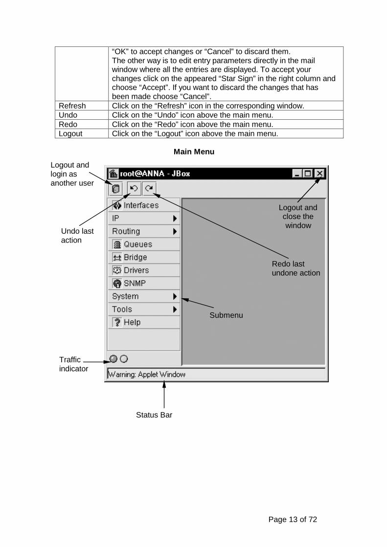
Main Menu
Redo lastundone action
Undo lastaction
Logout andlogin asanother user
Logout andclose thewindow
Status Bar
Trafficindicator
Submenu
Page 14 of 72
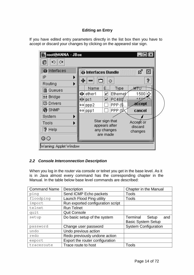
Editing an Entry
If you have edited entry parameters directly in the list box then you have toaccept or discard your changes by clicking on the appeared star sign.
2.2 Console Interconnection Description
When you log in the router via console or telnet you get in the base level. As itis in Java almost every command has the corresponding chapter in theManual. In the table below base level commands are described:
Command Name Description Chapter in the Manualping Send ICMP Echo packets Toolsfloodping Launch Flood Ping utility Toolsimport Run exported configuration scripttelnet Run Telnetquit Quit Consolesetup Do basic setup of the system Terminal Setup and
Basic System Setuppassword Change user password System Configurationundo Undo previous actionredo Redo previously undone actionexport Export the router configurationtraceroute Trace route to host Tools
Star sign thatappears afterany changes
are made
Accept ordiscard
changes

Page 15 of 72
btest Run bandwidth test to remotehost
Tools
interface/ Interface configuration Network InterfaceManagement
driver/ Driver management Device DriverManagement
sys/ System Configurationbridge/ Bridge Configurationsnmp/ SNMP configuration SMNP Service
Configurationterminal/ Set terminal type Terminal Setup and
Basic System Setupip/ IPv4 specific settings Internet Protocol
Managementrouting/ Routing protocol settings Advanced Routing
Management
The slash in the end of the command means that this command leads to thesubmenu.
2.2-1 How To
The table below describes how you can execute commands, move throughthe levels in the console, etc.
Command Actioncommand [Enter] Execute the command[?] Show the list of all available commandscommand [?] Display help on the command and the list of
argumentscommand argument [?] Display help on the command’s a[Tab] Complete the command/word. If the input is
ambiguous, a second [Tab] gives possible options/ Move up to the base level/command Execute the base level command.. Move up one level“” Enter an empty string“word1 word2” Enter space between words
You can abbreviate names of levels, commands and arguments.

Page 16 of 72
2.2-2 Import and Export
There is a possibility to export/import router configuration to/from the files, i.e.to create a new file or to add chosen configuration to an existing file either toimport configuration from a file to the router. These files are stored in the ftpaccess area of the router. That is where you can get by connecting to therouter via ftp using login and password of the user root.
Command export has the following parameters:
Parameter Name Description<filename> Export configuration to the file with
this nameappend Append configuration to a specified
file
Command import has only one parameter:
Parameter Name Description<filename> Import router configuration from a
specified file. File is taken from routerftp access area
Command export can be found in every level of the command tree. Byexecuting it you can export the configuration of a specified level. For exampleif you execute this command in “ip address” level you will get theinformation about IP addresses settings. But if you execute it in “ ip” level youwill get the information about all IP settings: NAT, Firewall, DHCP, etc.
To view the configuration as it will look like in the export file simply enter thecommand export without any parameter.
For example you want to make a file that consists of Firewall settings andNAT settings. The file name is test. Then you have to execute the followingcommands:
[MikroTik]> ip firewall export test[MikroTik]> ip nat export test append
The file can be accessed now by ftp (only user root can do that). Also theseconfigurations are ready to be imported any time:
[MikroTik]> import test

Page 17 of 72
3 Device Driver Management
Device drivers represent the software interface part of installed networkdevices. For example, the MikroTik system includes device drivers forNE2000 compatible Ethernet cards and other network devices. If you need adevice driver for a device, which is not on the list, please suggest it at oursuggestion page on our website.
Most device drivers are loaded automatically. For instructions on specificdevice drivers see the chart below.
Unloading of device driver is useful when changing network devices – this canbe useful in avoiding loading drivers for devices, which have been removedfrom the system. This may be done automatically by removing the card andrebooting before inserting the new network device. The device drivers can beremoved only if the appropriate interface has been disabled first.
3-1 Managing Device Drivers from Java
Select the “Drivers” menu to display the currently installed drivers. Newdrivers can be installed by selecting the “+”. Existing drivers can be removedby selecting the “-“ as long as their status is ‘disabled’ (set in the Interfacemenu). PCI drivers cannot be removed.
3-2 Managing Device Drivers from Console
Driver management commands are located in the “driver” menu.
Command syntax Descriptionload <driver name> [irq <IRQ>][io <IO range start>][mem <shared memory>]
Load driver
unload <number> Unload driverprint Show loaded drivers
Where <number> is number of a loaded driver, which can be viewed in thelist, generated by the “print” command.
3-3 Device Driver Parameters
Name in console Name in JAVA Descriptionname Driver Name of driver to install*irq IRQ Interrupt Request Number. Can be
omitted if device does not use IRQ.For IRQ probing enter 0 in Java Box.
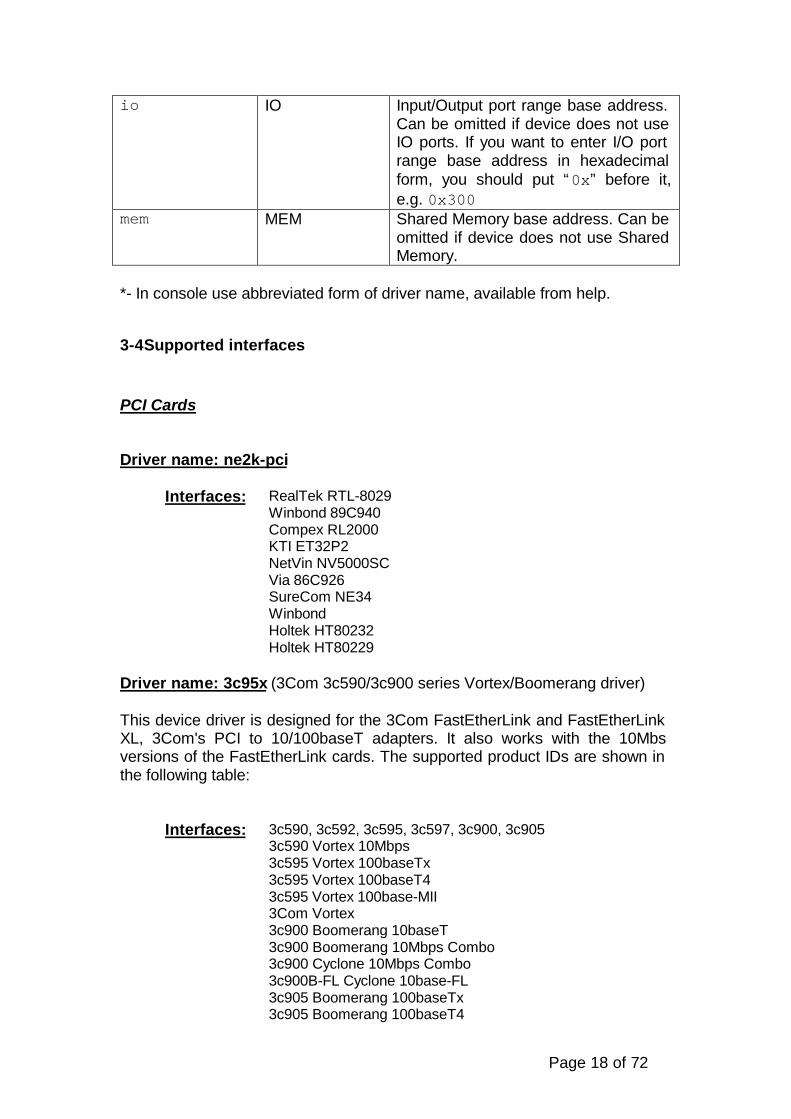
Page 18 of 72
io IO Input/Output port range base address.Can be omitted if device does not useIO ports. If you want to enter I/O portrange base address in hexadecimalform, you should put “0x” before it,e.g. 0x300
mem MEM Shared Memory base address. Can beomitted if device does not use SharedMemory.
*- In console use abbreviated form of driver name, available from help.
3-4 Supported interfaces
PCI Cards
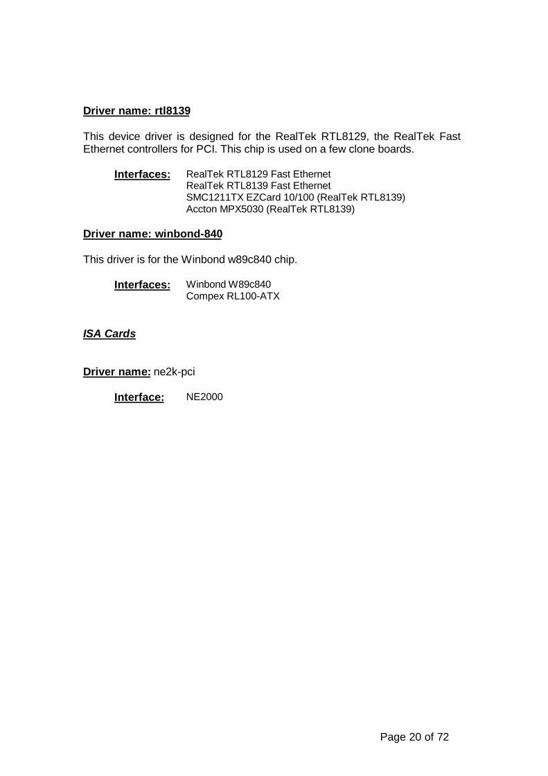
Driver name: ne2k-pci
Interfaces: RealTek RTL-8029Winbond 89C940Compex RL2000KTI ET32P2NetVin NV5000SCVia 86C926SureCom NE34WinbondHoltek HT80232Holtek HT80229
Driver name: 3c95x (3Com 3c590/3c900 series Vortex/Boomerang driver)
This device driver is designed for the 3Com FastEtherLink and FastEtherLinkXL, 3Com's PCI to 10/100baseT adapters. It also works with the 10Mbsversions of the FastEtherLink cards. The supported product IDs are shown inthe following table:
Interfaces: 3c590, 3c592, 3c595, 3c597, 3c900, 3c9053c590 Vortex 10Mbps3c595 Vortex 100baseTx3c595 Vortex 100baseT43c595 Vortex 100base-MII3Com Vortex3c900 Boomerang 10baseT3c900 Boomerang 10Mbps Combo3c900 Cyclone 10Mbps Combo3c900B-FL Cyclone 10base-FL3c905 Boomerang 100baseTx3c905 Boomerang 100baseT4

Page 19 of 72
3c905B Cyclone 100baseTx3c905B Cyclone 10/100/BNC3c905B-FX Cyclone 100baseFx3c905C Tornado3c980 Cyclone3cSOHO100-TX Hurricane3c555 Laptop Hurricane3c575 Boomerang CardBus3CCFE575 Cyclone CardBus3CCFE656 Cyclone CardBus3c575 series CardBus (unknown version)3Com Boomerang (unknown version)
Driver name: lmc
Interfaces: LanMedia LMC5200LanMedia LMC5245LanMedia LMC1000
Driver name: eepro100 (Intel i82557/i82558 PCI EtherExpressPro driver)
This device driver is designed for the Intel i82557 "Speedo3" chip, Intel'ssingle-chip fast Ethernet controller for PCI, as used on theIntelEtherExpressPro 100 adapter.
Driver name: tulip
This device driver is designed for the DECchip "Tulip", Digital'ssingle-chip ethernet controllers for PCI. Supported members of the familyare the 21040, 21041, 21140, 21140A, 21142, and 21143. Similar work-alikechips from Lite-On, Macronics, ASIX, Compex and other listed below are alsosupported.
Interfaces: Digital DC21040 TulipDigital DC21041 TulipDigital DS21140 TulipDigital DS21143 TulipLite-On 82c168 PNICMacronix 98713 PMACMacronix 98715 PMACMacronix 98725 PMACASIX AX88140Lite-On LC82C115 PNIC-IIADMtek AN981 CometCompex RL100-TXIntel 21145 TulipXircom Tulip clone
Page 20 of 72
Driver name: rtl8139
This device driver is designed for the RealTek RTL8129, the RealTek FastEthernet controllers for PCI. This chip is used on a few clone boards.
Interfaces: RealTek RTL8129 Fast EthernetRealTek RTL8139 Fast EthernetSMC1211TX EZCard 10/100 (RealTek RTL8139)Accton MPX5030 (RealTek RTL8139)
Driver name: winbond-840
This driver is for the Winbond w89c840 chip.
Interfaces: Winbond W89c840Compex RL100-ATX
ISA Cards
Driver name: ne2k-pci
Interface: NE2000

Page 21 of 72
4 Network Interface Management
4.1 Introduction
An Interface is physical or virtual device which provides a connection to anexternal network. Network interfaces are created automatically when theNetwork Interface Card driver is loaded. Virtual (software) interfaces can becreated manually.
4.1-1 Managing Network Interfaces from Java
Select the “Interfaces” menu to open the interface list window. The interfaceslist displays basic interface parameters. Interface type specific parameterscan be changed from interface details windows (opened by double clicking onicon to the left from interface name). The Interface details window has astandard “Traffic” tab which displays traffic that enters and leaves routerthrough the interface. It can also contain other tabs with interface type specificparameters.
The Interfaces list window also contains a “blink” button. Selecting this buttoncauses traffic to be generated on the highlighted interface and therefore blinkthe LEDs (light emitting diodes) on the card so that an administrator candetermine which Interface name corresponds to the actual interface (whenthere are multiple interfaces of the same type). Note that not all interfacessupport this function.
4.1-2 Managing Network Interfaces from Console
Network interface commands and submenus are located in “interface”menu. It contains several commands that are common to all interfaces:
Command syntax Descriptionprint Show interface summaryset <interface> [up] [down][name <new name>] [mtu <MTU>]
Change basic interfaceproperties
traffic <interface> Monitor traffic on interface
Where <interface> is interface name or number obtained from “print”command.
The “interface” menu also contains device type specific submenus withdevice type specific commands. The following device type submenus can beavailable, depending on what features are licensed for a particular installation:

Page 22 of 72
Submenu Descriptionether Ethernet interfaceslmc LMC Sync interfacesppp Async PPP interfacesipsec IPSec tunnelsradiolan RadioLAN interfacesarlan Arlan IC2200 interfacessync Moxa Sync interfacespc Aironet 35/45/4800 interfaceswavelan WaveLAN interfaces
4.1-3 Basic Interface Parameter Description
Name in console Name in Java Descriptionname Name Human friendly name for the interface.
Maximum 31 character.up Enabled (yes) Enable interfacedown Enabled (no) Disable interfacemtu MTU Maximum Transfer Unit (in bytes)
Enabled Enable or disable interface
4.2 Ethernet Interfaces
Ethernet interfaces include standard 10/100 Mbit Ethernet network interface.Ethernet interfaces do not have any device type dependent parameters. EachEthernet interface has its MAC-address (Media Access Control).
4.2-1 Managing Ethernet Interfaces from Java
Ethernet interface parameters can be changed from interface list window orfrom interface details window “General” tab.
4.2-2 Managing Ethernet Interfaces from Console
Ethernet interface management is done in submenu “interface ether”.
Command syntax Descriptionprint [<interface>] Show interface(s) informationset <interface> [up] [down][name <new name>] [mtu <MTU>]
Change interface properties
blink <interface> Generate traffic to blink LEDs
Where <interface> is interface name or number obtained from “print“command.
Page 23 of 72
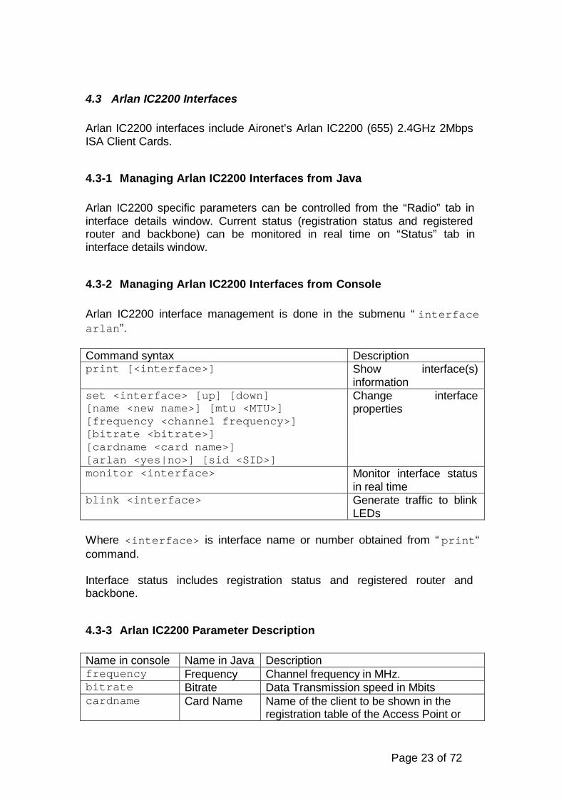
4.3 Arlan IC2200 Interfaces
Arlan IC2200 interfaces include Aironet’s Arlan IC2200 (655) 2.4GHz 2MbpsISA Client Cards.
4.3-1 Managing Arlan IC2200 Interfaces from Java
Arlan IC2200 specific parameters can be controlled from the “Radio” tab ininterface details window. Current status (registration status and registeredrouter and backbone) can be monitored in real time on “Status” tab ininterface details window.
4.3-2 Managing Arlan IC2200 Interfaces from Console
Arlan IC2200 interface management is done in the submenu “interfacearlan”.
Command syntax Descriptionprint [<interface>] Show interface(s)
informationset <interface> [up] [down][name <new name>] [mtu <MTU>][frequency <channel frequency>][bitrate <bitrate>][cardname <card name>][arlan <yes|no>] [sid <SID>]
Change interfaceproperties
monitor <interface> Monitor interface statusin real time
blink <interface> Generate traffic to blinkLEDs
Where <interface> is interface name or number obtained from “print“command.
Interface status includes registration status and registered router andbackbone.
4.3-3 Arlan IC2200 Parameter Description
Name in console Name in Java Descriptionfrequency Frequency Channel frequency in MHz.bitrate Bitrate Data Transmission speed in Mbitscardname Card Name Name of the client to be shown in the
registration table of the Access Point or
Page 24 of 72
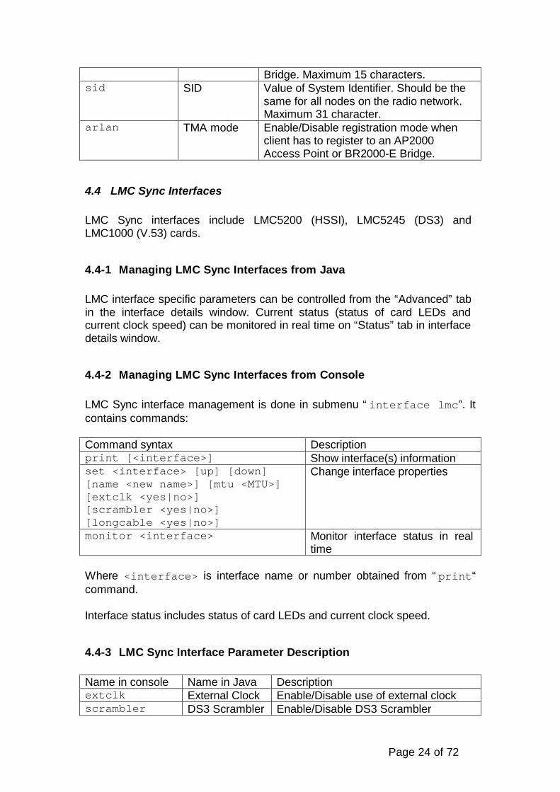
Bridge. Maximum 15 characters.sid SID Value of System Identifier. Should be the
same for all nodes on the radio network.Maximum 31 character.
arlan TMA mode Enable/Disable registration mode whenclient has to register to an AP2000Access Point or BR2000-E Bridge.
4.4 LMC Sync Interfaces
LMC Sync interfaces include LMC5200 (HSSI), LMC5245 (DS3) andLMC1000 (V.53) cards.
4.4-1 Managing LMC Sync Interfaces from Java
LMC interface specific parameters can be controlled from the “Advanced” tabin the interface details window. Current status (status of card LEDs andcurrent clock speed) can be monitored in real time on “Status” tab in interfacedetails window.
4.4-2 Managing LMC Sync Interfaces from Console
LMC Sync interface management is done in submenu “interface lmc”. Itcontains commands:
Command syntax Descriptionprint [<interface>] Show interface(s) informationset <interface> [up] [down][name <new name>] [mtu <MTU>][extclk <yes|no>][scrambler <yes|no>][longcable <yes|no>]
Change interface properties
monitor <interface> Monitor interface status in realtime
Where <interface> is interface name or number obtained from “print“command.
Interface status includes status of card LEDs and current clock speed.
4.4-3 LMC Sync Interface Parameter Description
Name in console Name in Java Descriptionextclk External Clock Enable/Disable use of external clockscrambler DS3 Scrambler Enable/Disable DS3 Scrambler
Page 25 of 72
longcable Long DS3Cable
Enable/Disable long DS3 cable
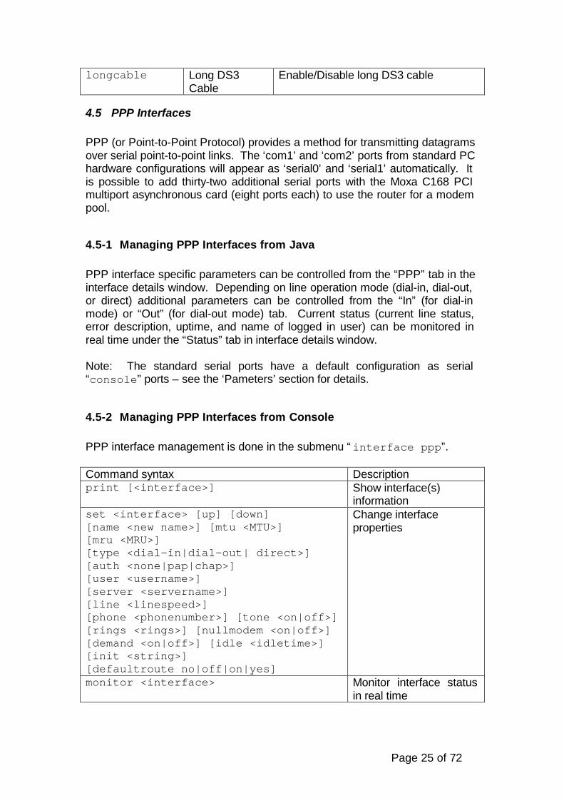
4.5 PPP Interfaces
PPP (or Point-to-Point Protocol) provides a method for transmitting datagramsover serial point-to-point links. The ‘com1’ and ‘com2’ ports from standard PChardware configurations will appear as ‘serial0’ and ‘serial1’ automatically. Itis possible to add thirty-two additional serial ports with the Moxa C168 PCImultiport asynchronous card (eight ports each) to use the router for a modempool.
4.5-1 Managing PPP Interfaces from Java
PPP interface specific parameters can be controlled from the “PPP” tab in theinterface details window. Depending on line operation mode (dial-in, dial-out,or direct) additional parameters can be controlled from the “In” (for dial-inmode) or “Out” (for dial-out mode) tab. Current status (current line status,error description, uptime, and name of logged in user) can be monitored inreal time under the “Status” tab in interface details window.
Note: The standard serial ports have a default configuration as serial“console” ports – see the ‘Pameters’ section for details.
4.5-2 Managing PPP Interfaces from Console
PPP interface management is done in the submenu “interface ppp”.
Command syntax Descriptionprint [<interface>] Show interface(s)
informationset <interface> [up] [down][name <new name>] [mtu <MTU>][mru <MRU>][type <dial-in|dial-out| direct>][auth <none|pap|chap>][user <username>][server <servername>][line <linespeed>][phone <phonenumber>] [tone <on|off>][rings <rings>] [nullmodem <on|off>][demand <on|off>] [idle <idletime>][init <string>][defaultroute no|off|on|yes]
Change interfaceproperties
monitor <interface> Monitor interface statusin real time
Page 26 of 72
Where <interface> is interface name or number obtained from “print“command.
Interface status includes current line status, error description (if any), uptimeand name of logged in user.
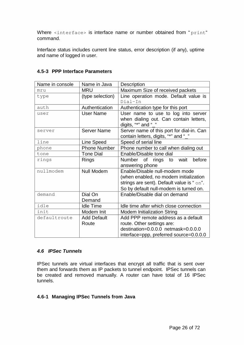
4.5-3 PPP Interface Parameters
Name in console Name in Java Descriptionmru MRU Maximum Size of received packetstype (type selection) Line operation mode. Default value is
Dial-Inauth Authentication Authentication type for this portuser User Name User name to use to log into server
when dialing out. Can contain letters,digits, “*” and “_”
server Server Name Server name of this port for dial-in. Cancontain letters, digits, “*” and “_”
line Line Speed Speed of serial linephone Phone Number Phone number to call when dialing outtone Tone Dial Enable/Disable tone dialrings Rings Number of rings to wait before
answering phonenullmodem Null Modem Enable/Disable null-modem mode
(when enabled, no modem initializationstrings are sent). Default value is “on”.So by default null-modem is turned on.
demand Dial OnDemand
Enable/Disable dial on demand
idle Idle Time Idle time after which close connectioninit Modem Init Modem Initialization Stringdefaultroute Add Default
RouteAdd PPP remote address as a defaultroute. Other settings are:destination=0.0.0.0 netmask=0.0.0.0interface=ppp, preferred source=0.0.0.0
4.6 IPSec Tunnels
IPSec tunnels are virtual interfaces that encrypt all traffic that is sent overthem and forwards them as IP packets to tunnel endpoint. IPSec tunnels canbe created and removed manually. A router can have total of 16 IPSectunnels.
4.6-1 Managing IPSec Tunnels from Java

Page 27 of 72
IPSec specific parameters can be controlled from the “IPsec” tab in interfacedetails window. New IPSec tunnels can be created by selecting the “Add”button in interface list window. IPSec interfaces can be removed by selectingthe “Remove” [-] button in interface list window.
4.6-2 Managing IPSec Tunnels from Console
IPSec tunnel management is done in the submenu “interface ipsec”.
Command syntax Descriptionprint [<interface>] Show interface(s)
informationadd <interface> [up] [down][name <new name>] [mtu <MTU>]remote <remote IP> spibase <spibase>mode <MD5-3DES|MD5-DES> ahkey <ahkey>espkey <espkey> [myside <left|right>]
Add IPSec tunnel
set <interface> [up] [down][name <new name>] [mtu <MTU>][remote <remote IP>][spibase <spibase>][mode <MD5-3DES|MD5-DES>][ahkey <ahkey>] [espkey <espkey>][myside <left|right>]
Change interfaceproperties
monitor <interface> Monitor interface statusin real time
remove <interface> Remove IPSec tunnel
Where <interface> is interface name or number obtained from “print“command.
Interface status includes registration status and registered router andbackbone.
4.6-3 IPSec Tunnel Parameters
Name in console Name in Java Descriptionremote Remote
AddressIP address of remote endpoint oftunnel
spibase SPI Base SPI Basemode Encryption
modeEncryption mode to use to encryptpackets
ahkey AH Key Authentication Header Keyespkey ESP Key ESP Keymyside Side Side of tunnel. Must be different for
each end of tunnel.

Page 28 of 72
4.7 RadioLAN Interfaces
RadioLAN interface supports the RadioLAN ISA CardLINK – Model 10110Mbit radio card.
4.7-1 Managing RadioLAN Interfaces from Java
RadioLAN specific parameters can be controlled from the “Radio” tab ininterface details window. Current status (current default destination) can bemonitored in real time on “Status” tab in interface details window.
RadioLAN interfaces have an additional capability of low level radioconnection testing. Test can be started and results monitored in real time onunder the “Ping” tab.
4.7-2 Managing RadioLAN Interfaces from Console
RadioLAN interface management is done in submenu “interfaceradiolan”.
Command syntax Descriptionprint [<interface>] Show interface(s)
informationset <interface> [up] [down][name <new name>] [mtu <MTU>][distance <distance>][txdiv <on|off>][rxdiv <on|off>][mode<alone|ap|cfg|firstap|firstclient>][maxretr <maxretries>] [sid <SID>][clientname <clientname>][cfgdst <destination>]
Change interfaceproperties
monitor <interface> Monitor interface statusin real time
table <interface> Show neighbor tabletest <interface>address <MAC address>[total <total>] [size <size>]
Test link to remoteRadioLAN host
blink <interface> Generate traffic to blinkLEDs
Where <interface> is an interface name or number obtained from “print“command. Interface status includes current default destination.

Page 29 of 72
4.7-3 RadioLAN Interface Parameters
Name in console Name in Java Descriptiondistance Distance Distance to remote end of point to
point linktxdiv Tx Diversity Enable/Disable transmit diversityrxdiv Rx Diversity Enable/Disable receive diversitymode Default destination Operation modemaxretr Maximum Retries Maximum retries to use when
sendingsid SID System Identifier (4 chars max)clientname Name Client name string. 15 characters
maximum.cfgdst (Default destination
string)Configured destination. Used onlyin operation mode when defaultdestination is configured.
Test utility parameters:
Name in console Name in Java Descriptionaddress Ping To MAC address of host to test link tototal Packets Total number of packets to use in testsize Packet Size Size of test packets
4.8 Moxa Sync Interfaces
Moxa Sync interfaces supports the Moxa C101 Sync adapters.
4.8-1 Managing Moxa Sync Interfaces from Java
Moxa Sync specific parameters can be controlled from “Synchronous” tab ininterface details window. Current status (status of modem control lines, timesince last keepalive and sequence number difference) can be monitored inreal time under the “Status” tab in interface details window.
4.8-2 Managing Moxa Sync Interfaces from Console
Moxa Sync interface management is done in submenu “interface sync”.
Command syntax Descriptionprint [<interface>] Show interface(s)
informationset <interface> [up] [down][name <new name>] [mtu <MTU>][keepalive <keepalive>][speed <speed>]
Change interfaceproperties
Page 30 of 72
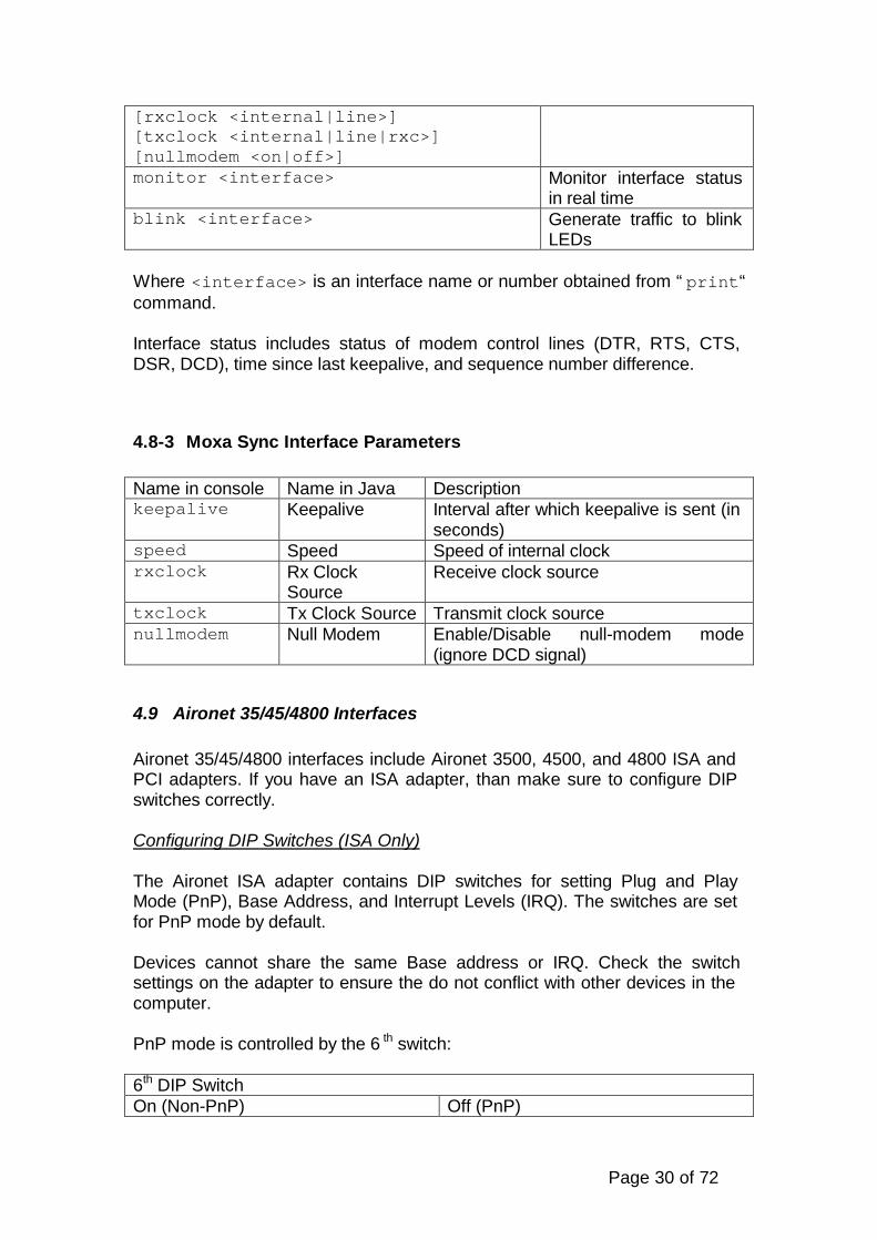
[rxclock <internal|line>][txclock <internal|line|rxc>][nullmodem <on|off>]monitor <interface> Monitor interface status
in real timeblink <interface> Generate traffic to blink
LEDs
Where <interface> is an interface name or number obtained from “print“command.
Interface status includes status of modem control lines (DTR, RTS, CTS,DSR, DCD), time since last keepalive, and sequence number difference.
4.8-3 Moxa Sync Interface Parameters
Name in console Name in Java Descriptionkeepalive Keepalive Interval after which keepalive is sent (in
seconds)speed Speed Speed of internal clockrxclock Rx Clock
SourceReceive clock source
txclock Tx Clock Source Transmit clock sourcenullmodem Null Modem Enable/Disable null-modem mode
(ignore DCD signal)
4.9 Aironet 35/45/4800 Interfaces
Aironet 35/45/4800 interfaces include Aironet 3500, 4500, and 4800 ISA andPCI adapters. If you have an ISA adapter, than make sure to configure DIPswitches correctly.
Configuring DIP Switches (ISA Only)
The Aironet ISA adapter contains DIP switches for setting Plug and PlayMode (PnP), Base Address, and Interrupt Levels (IRQ). The switches are setfor PnP mode by default.
Devices cannot share the same Base address or IRQ. Check the switchsettings on the adapter to ensure the do not conflict with other devices in thecomputer.
PnP mode is controlled by the 6 th switch:
6th DIP SwitchOn (Non-PnP) Off (PnP)

Page 31 of 72
If you set PnP mode on then all other settings are not taken into account. Ifyou still want to use PnP mode make sure that the default IRQ and BaseAddress do not conflict with the other devices. The default are:
Base Address IRQ Level140 5
If you want to configure other IRQ and Base Address values, make sure PnPmode is turned off, i.e. 6 th switch is On.
4.9-1 Managing Aironet 35/45/4800 Interfaces from Java
Aironet 35/45/4800 specific parameters can be controlled from “General”, “RFNetwork,” and “Advanced” tabs in interface details window. Current status(current signal quality, channel frequency, synchronization and associationstatus, name of Access Point, and MAC address of Access Point) can bemonitored in real time under the “Status” tab in interface details window.
4.9-2 Managing Aironet 35/45/4800 Interfaces from Console
Aironet 35/45/4800 interface management is done in the submenu“interface pc“.
Command syntax Descriptionprint [<interface>] Show interface(s)
informationset <interface> [up] [down][name <new name>] [mtu <MTU>][type <ad-hoc|infrastructure>][rtsthres <RTSthres>][fragthres <fragthres>][txpower <power>][rxdiv <default|both|left|right>][txdiv <default|both|left|right>][longretr <longretr>][shortretr <shortretr>][channel <channel>] [rate <rate>][ap1 <AP1>] [ap2 <AP2>] [ap3 <AP3>][ap1 <AP4>] [ssid1 <ssid1>][ssid2 <ssid2>] [ssid3 <ssid3>][modulation <CCK|MBOK|default>][clientname <client name>][bperiod <bperiod>]
Change interfaceproperties
monitor <interface> Monitor interface statusin real time
Where <interface> is interface name or number obtained from “print“command.

Page 32 of 72
Interface status includes current signal quality, channel frequency,synchronization, association, name of Access Point, and MAC address ofAccess Point.
4.9-3 Aironet 35/45/4800 Interface Parameters
Name in console Name in Java Descriptiontype Infrastructure Mode Operation mode of card (ad hoc or
infrastructure). Default value is“infrastructure”
rtsthres RTS threshold RTS Thresholdfragthres Fragmentation
thresholdFragmentation threshold
power Transmit Power Transmit powerrxdiv Receive Antenna Receive diversitytxdiv Transmit Antenna Transmit diversitylongretr Long Retries Long retry limitshortretr Short Retries Short retry limitchannel Channel Channel frequencyrate Data Rate Data rateap1 Access Point 1 Access Point 1 (MAC Address)ap2 Access Point 1 Access Point 2 (MAC Address)ap3 Access Point 1 Access Point 3 (MAC Address)ap4 Access Point 1 Access Point 4 (MAC Address)ssid1 SSID1 Service Set Identifier 1ssid2 SSID2 Service Set Identifier 2ssid3 SSID3 Service Set Identifier 3modulation Modulation Modulation modeclientname Client name Client namebperiod Beacon period Beacon period
Read the User Guide for details how to connect to the Access Point.
4.10 WaveLAN Interfaces Base Configuration
WaveLAN interfaces support 802.11 standard, i.e. it works with Aironetaccess points and works at 11Mbps rate. Tx power: 35 mW.
This interfaces needs the same license, as for Aironet 4800 interfaces. Thedriver is loaded automatically, when you boot up the router with the PCMCIAWaveLAN Network Adapter.

Page 33 of 72
4.10-1 Managing WaveLAN Interfaces from Console
WaveLAN interface management is done in the submenu “interfacewavelan“.
Command syntax Descriptionprint [<interface>] Show interface(s)
informationset <interface> [up] [down][nick <new nickname>] [mtu <MTU>][mode <ad-hoc|infrastructure>][rts <RTSthres>][frag <fragthres>][txpower <power>][freq <frequency>][rate <rate>][essid <essid>]
Change interfaceproperties
exportblinkmonitor <interface> Monitor interface status
in real time
Where <interface> is interface name or number obtained from “print“command.
4.10-2 WaveLAN Interface Parameters
Name in console Name in Java Descriptionmode Infrastructure Mode Operation mode of card (ad hoc or
infrastructure). Default value is“infrastructure”
rts RTS threshold RTS Threshold. Value can be from0 till 2347
frag Fragmentationthreshold
Fragmentation threshold. Valuescan be from 256 till 2346
freq Frequency Frequency for a network in Ad-Hocmode.
rate Data Rate Data rate. Can be 1, 2, 5.5, 11 orauto.
essid SSID Network name. You should write inAccess Point ssid. If not define,can connect to any AP
nick Nickname Card nickname

Page 34 of 72
5 Bridge Configuration
Bridging is used to pass MAC layer packets between interfaces without anyrouting. When the routers are used in bridging mode, Spanning Tree Protocolis used to avoid bridging loops and to communicate information betweenrouters/bridges. Bridging works only for Ethernet and RadioLan interfaces.You can bridge between Ethernet and RadioLan networks, only the routershould be a default destination (on MAC level) for others clients of the radionetwork. Also you can bridge Ethernet networks through RadioLan network(point-to-point).
5-1 Configuring Bridge from Java
Select the Bridge menu. Various protocols can be enabled or disabled.
5-2 Configuring Bridge from Console
Bridge configuration commands are located in “bridge” menu.
Command syntax DescriptionPrint Show bridge
configurationset [bridge <on|off>] [ip <on|off>][ipx <on|off>] [ipv6 <on|off>][atalk <on|off>]
Change bridgeconfiguration
5-3 Bridge Configuration Parameters
Name in console Name in Java Descriptionbridge Enabled Enable/disable bridgeip IP Enable/disable bridging of IP protocolipx IPX Enable/disable bridging of IPX protocolipv6 IPv6 Enable/disable bridging of IPv6
protocolatalk AppleTalk Enable/disable bridging of AppleTalk
protocol
Page 35 of 72
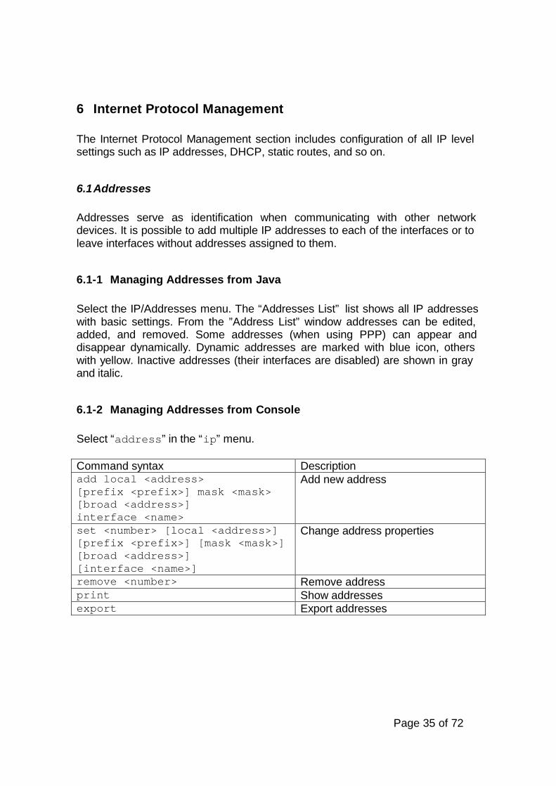
6 Internet Protocol Management
The Internet Protocol Management section includes configuration of all IP levelsettings such as IP addresses, DHCP, static routes, and so on.
6.1 Addresses
Addresses serve as identification when communicating with other networkdevices. It is possible to add multiple IP addresses to each of the interfaces or toleave interfaces without addresses assigned to them.
6.1-1 Managing Addresses from Java
Select the IP/Addresses menu. The “Addresses List” list shows all IP addresseswith basic settings. From the ”Address List” window addresses can be edited,added, and removed. Some addresses (when using PPP) can appear anddisappear dynamically. Dynamic addresses are marked with blue icon, otherswith yellow. Inactive addresses (their interfaces are disabled) are shown in grayand italic.
6.1-2 Managing Addresses from Console
Select “address” in the “ip” menu.
Command syntax Descriptionadd local <address>[prefix <prefix>] mask <mask>[broad <address>]interface <name>
Add new address
set <number> [local <address>][prefix <prefix>] [mask <mask>][broad <address>][interface <name>]
Change address properties
remove <number> Remove addressprint Show addressesexport Export addresses

Page 36 of 72
6.1-3 General Address Parameters
Name in Console Name in Java Descriptioninterface Interface Name of interface the address will be used
withlocal Local Address Local IP address for the interface.mask Network Mask Network Mask to be used with the prefix.prefix Prefix (optional) Network Prefix to be used with
the address. It shows what network can bereached through the interface with thegiven IP address. If not specified, will becalculated from Local Address andNetwork Mask.
broad BroadcastAddress
(optional) Broadcast Address to be usedwith the address. If not specified, will becalculated from Local Address andNetwork Mask.
6.2 Routes
Routes are needed for communicating with networks that are not directlyattainable via the router’s local interfaces. Routes to locally connected interfacesand networks are created automatically based on the IP address assigned tolocal interfaces. Static routes, including the default route, are set in theIP/Routes menu. Other automatic routes are created by routing daemons, suchas RIP and OSPF, which can be found in the Routing menu from the base level.Dynamic routes are shown in IP/Routes, too.
6.2-1 Managing Routes from Java
Select the “Routes” menu under the “IP” menu. The “Routes List” shows currentroutes settings which can be edited, added, and deleted. Disabled routes(interface they are using is disabled) are shown in gray and italic. Dynamic routesare marked with blue icon, others with red.
6.2-2 Managing Routes from Console
Select th submenu “ip route”.
Command syntax Descriptionadd interface <name>[gw <address>][dst<address>][mask <mask>]
Add new route

Page 37 of 72
[prefsrc <address>]set <number> [dst <address>][mask <mask>] [gw <address>][prefsrc <address>][interface <name>]
Change route properties
Remove <number> Remove routeprint Show routesexport Export routes
6.2-3 General Routes Parameters
Name in console Name in Java Descriptiondst Dst. Address Destination IP address of a host or networkmask Netmask Network Mask of the destinationgw Gateway Next gateway to the destinationinterface Interface Interface to be usedprefsrc Pref. Source (optional) Source Address of packets
leaving the router via this route
6.3 ARP
ARP (Address Resolution Protocol) displays IP addresses and respective MACaddresses of interfaces which are physically connected to local interface. TheARP table entries appear automatically as it sends broadcast messages to allinterfaces physically connected to the local interfaces. It is possible to manuallyassign static ARP entries.
6.3-1 Managing ARP from Java
Select the ‘ARP’ menu under the ‘IP’ menu. The ‘ARP List’ displays IPaddresses, MAC addresses, and interface names and allows to edit, add, andremove ARP entries. Inactive entries are shown in gray color and italic font.Permanent entries are marked with red icon.
6.3-2 Managing ARP from Console
Select the located in “address” menu that is in the “ip” menu.
Command syntax Descriptionadd interface <name>ip <address> mac <address>
Add static ARP entry
set <number> Change ARP entry

Page 38 of 72
[interface <name>][ip <address>][mac <address>]remove <number> Remove ARP entryprint Show ARP entriesexport Export ARP entries
6.3-3 General ARP Parameters
Name in console Name in Java Descriptonip IP Address IP addressmac Hardware Address MAC addressinterface Interface Interface name
6.4 PPP
Here you can setup PPP IP related settings: addresses, RADIUS and DNS whichwill be imparted to PPP clients.
6.4-1 Managing PPP from Java
Select the IP/Addresses menu. The “PPP IP Settings” list allows configuration oflocal address and remote address. To edit DNS and RADIUS server settings,select the details box located next to the refresh icon.
6.4-2 Managing PPP from Console
Management of PPP is done in the “ip ppp”. The following commands can beexecuted there:
Command syntax Descriptionprint Show interfacesdns PPP DNS settings menuradius PPP RADIUS settings menuset <interface>[local <address>][remote <address>]
Change IP address settings
export Export IP address settings
Page 39 of 72
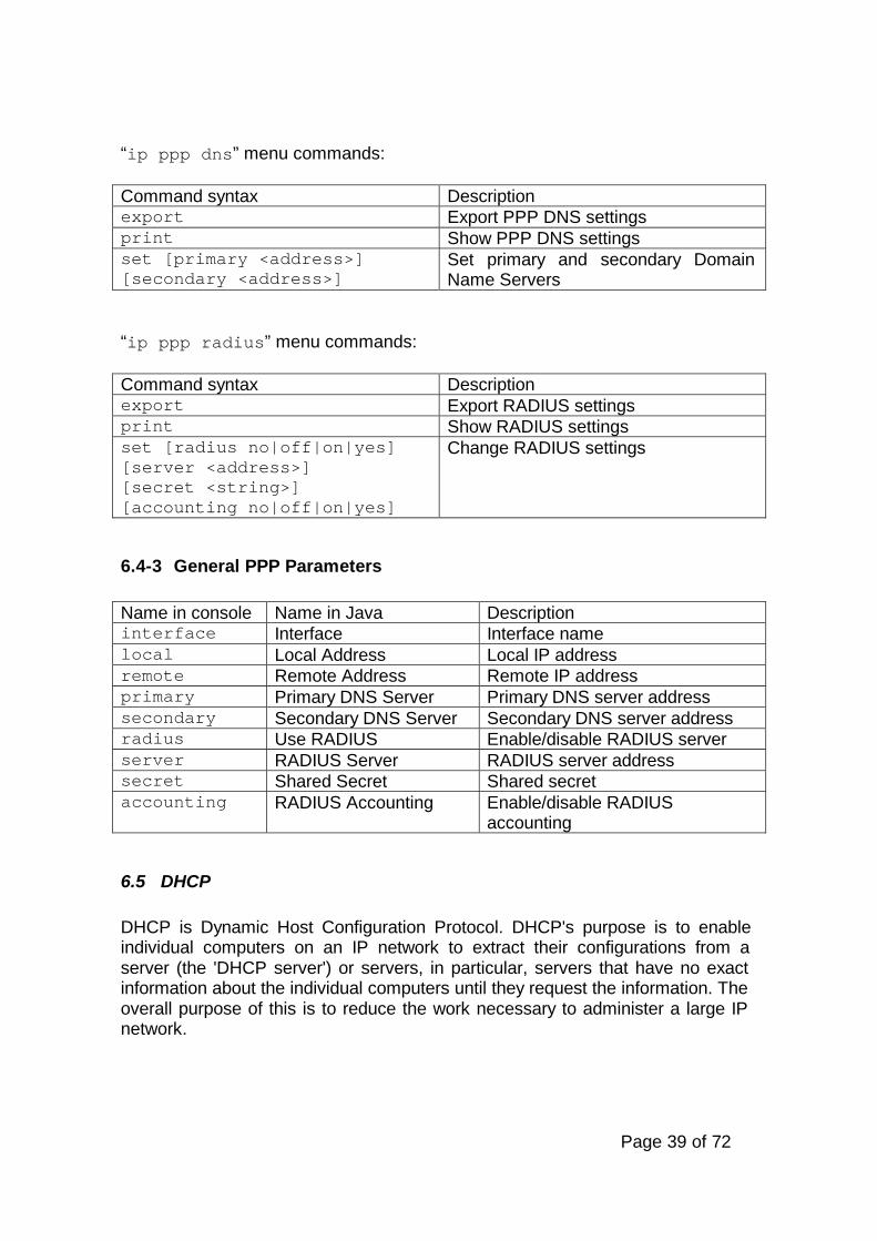
“ip ppp dns” menu commands:
Command syntax Descriptionexport Export PPP DNS settingsprint Show PPP DNS settingsset [primary <address>][secondary <address>]
Set primary and secondary DomainName Servers
“ip ppp radius” menu commands:
Command syntax Descriptionexport Export RADIUS settingsprint Show RADIUS settingsset [radius no|off|on|yes][server <address>][secret <string>][accounting no|off|on|yes]
Change RADIUS settings
6.4-3 General PPP Parameters
Name in console Name in Java Descriptioninterface Interface Interface namelocal Local Address Local IP addressremote Remote Address Remote IP addressprimary Primary DNS Server Primary DNS server addresssecondary Secondary DNS Server Secondary DNS server addressradius Use RADIUS Enable/disable RADIUS serverserver RADIUS Server RADIUS server addresssecret Shared Secret Shared secretaccounting RADIUS Accounting Enable/disable RADIUS
accounting
6.5 DHCP
DHCP is Dynamic Host Configuration Protocol. DHCP's purpose is to enableindividual computers on an IP network to extract their configurations from aserver (the 'DHCP server') or servers, in particular, servers that have no exactinformation about the individual computers until they request the information. Theoverall purpose of this is to reduce the work necessary to administer a large IPnetwork.

Page 40 of 72
6.5-1 Managing DHCP from Java
Select the “DHCP” menu under the ”IP” menu.
6.5-2 Managing DHCP from Console
DHCP management can is controlled from the “dhcp” menu under the “ip”menu. The “dhcp” menu “lease” option shows all current DHCP leases.“ip dhcp” menu commands:
Command syntax Descriptionlease DHCP leases menuprint Show DHCP interfacesexport Export DHCP settingsset <interface> [dhcp on|off][from <address>] [to <address>][lease <hh:mm:ss>][srcaddr <address>][mask <mask>][gateway <gateway>][domain <name>] [dns <address>]
Set DHCP interface properties
“ip dhcp lease” menu commands:
Command syntax Descriptionprint Show current DHCP leases
6.5-3 General DHCP Parameters
Name in console Name in Java Descriptioninterface Interface Interface namedhcp Enabled Enable/disable DHCPfromto
AddressFromTo
The range of IP addresses that can begiven to the clients.
lease Lease Time Time in hh:mm:ss the lease will be givenout.
srcaddr Src. Address Source address of the router’s DHCPinterface to be used by the client whencontacting the router.
mask Netmask Network mask to be used with the IPaddress.
gateway Gateway Default gateway to be used by the client.domain Domain Name Domain name assigned to the client.

Page 41 of 72
dns DNS ServerAddress
DNS server address to be used by theclient for address resolution.
Lease parameters (read only):
Name in console Name in Java DescriptionInterface Interface Interface nameIP address IP Address Client IP addressMAC address Hw. Address Client MAC addressLease time Lease Time Lease time. Value should be
hh:mm:ss, where hh is hours,mm is minutes and ss isseconds.
6.6 Firewall
Firewall supports filtering and security functions that are used to manage dataflows to the router and through it. Along with the Network Address Translationthey serve as security tools for preventing unauthorized access to networks.
Filtering rules organized together in chains do packet filtering. Each chain can beconsidered as a set of rules. There are three default chains, which cannot bedeleted. More chains can be added for grouping together filtering rules. Whenprocessing a chain, rules are taken from the chain in the order they are listedfrom the top to the bottom.
Packets entering the router through one of the interfaces are first matchedagainst the filtering rules of the Input chain. If the packet is not dropped orrejected, and it is for the router itself, the packet is delivered locally. If the packetis not dropped or rejected, but it has to be delivered outside the router, then thepacket is processed according to the routing table. If the processing issuccessful, then the packet is matched to the filtering rules of the forward chain.After that, packet is passed to the output interface and processed according tothe rules of output chain.
Packets originated from the router are processed according to the output chainonly.
The firewall also has a packet “mark” feature which is used to mark packet flowsfor the standard queuing process and bandwidth allocation.
Page 42 of 72
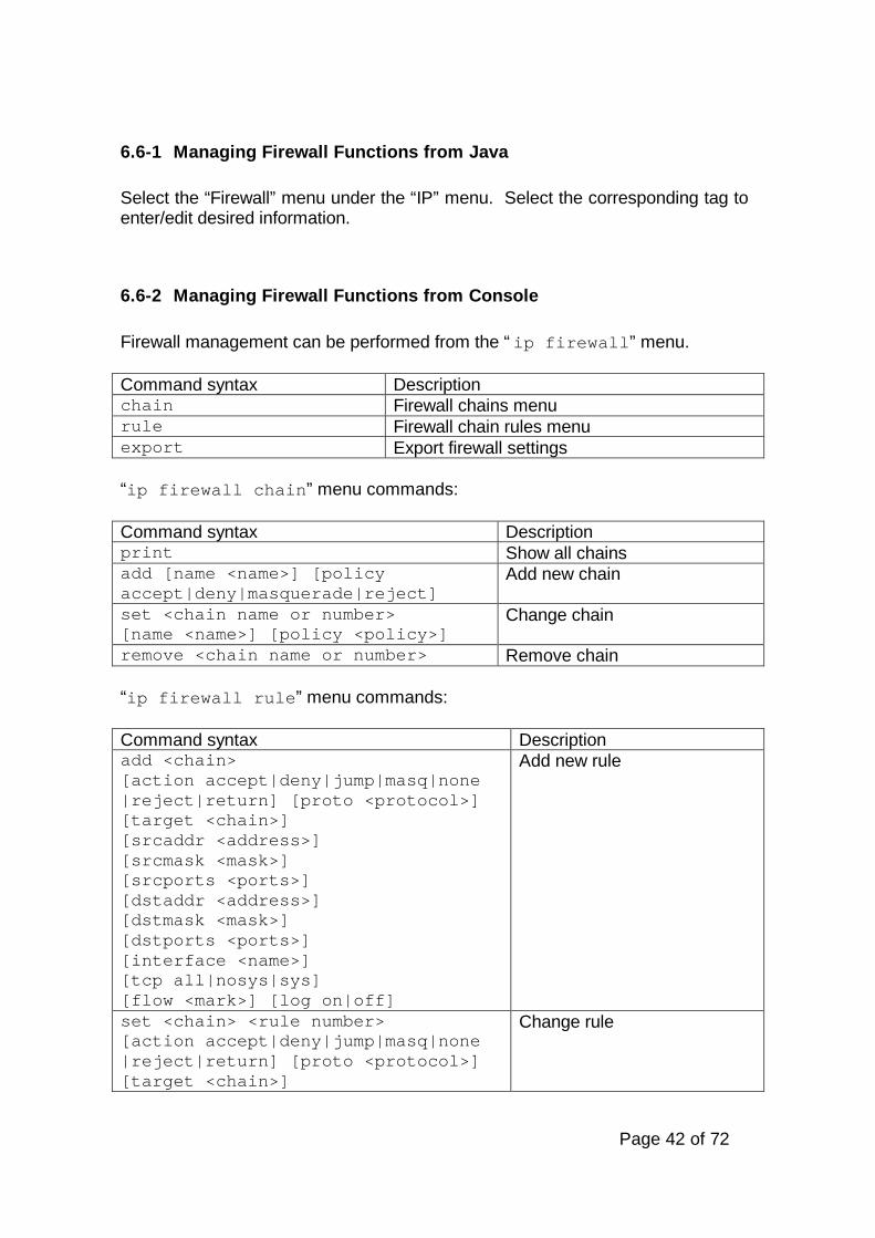
6.6-1 Managing Firewall Functions from Java
Select the “Firewall” menu under the “IP” menu. Select the corresponding tag toenter/edit desired information.
6.6-2 Managing Firewall Functions from Console
Firewall management can be performed from the “ip firewall” menu.
Command syntax Descriptionchain Firewall chains menurule Firewall chain rules menuexport Export firewall settings
“ip firewall chain” menu commands:
Command syntax Descriptionprint Show all chainsadd [name <name>] [policyaccept|deny|masquerade|reject]
Add new chain
set <chain name or number>[name <name>] [policy <policy>]
Change chain
remove <chain name or number> Remove chain
“ip firewall rule” menu commands:
Command syntax Descriptionadd <chain>[action accept|deny|jump|masq|none|reject|return] [proto <protocol>][target <chain>][srcaddr <address>][srcmask <mask>][srcports <ports>][dstaddr <address>][dstmask <mask>][dstports <ports>][interface <name>][tcp all|nosys|sys][flow <mark>] [log on|off]
Add new rule
set <chain> <rule number>[action accept|deny|jump|masq|none|reject|return] [proto <protocol>][target <chain>]
Change rule

Page 43 of 72
[srcaddr <address>][srcmask <mask>][srcports <ports>][dstaddr <address>][dstmask <mask>][dstports <ports>][interface <name>|all][tcp all|nosys|sys][flow <mark>][log on|off]remove <chain name or number><rule number>
Remove rule
move <chain> <source> <destination> Move rule in this chain fromsource number to destinationnumber
print <chain name or number> Show rules
6.6-3 General Firewall Parameters
Rule parameters:
Name in console Name in Java Descriptionaction Action Action to performlog Log Turns on or off logs writing option.srcaddrsrcmasksrcports
SourceAddressMaskPort
Source address, mask, and port of thepacket.Default port 0 means all ports 1-65535. ForICMP packets, port parameter means ICMPpacket type.
dstaddrdstmaskdstports
Destination AddressMaskPort
Destination address, mask, and port of thepacketDefault port 0 means all ports 1-65535. ForICMP packets, port parameter means ICMPpacket code.
proto Protocol Protocol name of the packet:all, icmp, tcp, udp etc.
interface Interface Interface name or all for any interfacetcp TCP Options Can be specified only if tcp is selected.target Target Chain Can be specified if action is ‘jump’flow Flow Mark Mark for the packet to be used in further
actions (queuing). Flow mark is used onlyinside the router, and it is lost when thepacket exits the router. If there are severalrules for marking the packet, the packet ismarked with the flow mark from the lastapplied rule.

Page 44 of 72
Actions to perform on rules:
Action name in console Action name in Java Descriptionaccept Accept Accept everythingreject Reject Reject everything and send
ICMP reject messagedeny Deny Silently drop the packet (without
sending the ICMP rejectmessage)
masq Masq Use masqueradingreturn Return Return to the chain from which
this rule has been invokedjump Jump Jump to another chain
Chain parameters:
Name in console Name in Java Descriptionname Name Chain namepolicy Policy Chain policy
6.7 NAT
NAT (Network Address Translation) is the translation of an IP address usedwithin one network to a different IP address known within another network. Onenetwork is designated the inside network and the other is the outside. Typically,an administrator maps the local inside network addresses to one or more globaloutside IP addresses and unmaps the global IP addresses on incoming packetsback into local IP addresses. This helps ensure security since each outgoing orincoming request must go through a translation process that also offers theopportunity to qualify or authenticate the request or match it to a previousrequest. NAT also conserves the number of global IP addresses and it lets thewhole network use a single IP address in its communication with the world.
6.7-1 Managing NAT from Java
Select the “NAT” menu under the “IP”. The “NAT” list allows editing, adding, andremoving NAT entries.

Page 45 of 72
6.7-2 Managing NAT from Console
Network Address Translation management is performed in the “ip nat” menu.
Command syntax Descriptionprint Show NAT rulesexport Export NAT rulesmove <source number><destination number>
Move NAT rule fromsource number todestination number
remove <rule number> Remove NAT ruleadd [interface <name>] [scr <address>][smask <mask>] [dst <address>][dmask <mask>] [rotocol <protocol>][spots <port range>][dports <port range>][nat-src <address>][nat-dst <address>] [nat-smask <mask>][nat-dmask <mask>] [nat-sport <potr>][nat-dport <port>] [translate on|off][direction in|out]
Add NAT rule
set <number> [interface <name>][scr <address>] [smask <mask>][dst <address>] [dmask <mask>][rotocol <protocol>][spots <port range>][dports <port range>][nat-src address>][nat-dst <address>] [nat-smask <mask>][nat-dmask <mask>] [nat-sport <potr>][nat-dport <port>] [translate on|off][direction in|out]
Change NAT rule
6.7-3 General NAT Parameters
Name in console Name in Java Descriptiondirectionin|out
Direction The direction of the packet, where in meansfrom the interface into the router, and outmeans from the router to the interface.
srcsmasksports
SourceAddr:Mask:Port:
Source address, mask, and port of thepacket(default port 0 means all ports 1-65535)
dstdmaskdports
DestinationAddr:Mask:
Destination address, mask, and port of thepacket(default port 0 means all ports 1-65535)

Page 46 of 72
Port:interface Interface Name of the interface the packet is passing
throughprotocol Protocol Protocol name of the packet:
all, icmp, tcp, etc.translate Translate Designates the action to perform on packet –
translate or leave unchangednat-srcnat-smasknat-sport
SourceAddr:Mask:Port:
New source address, mask, and port of thepacket(port 0 and address 0.0.0.0 mean: leaveunchanged)
nat-dstnat-dmasknat-dport
DestinationAddr:Mask:Port:
New destination address, mask, and port ofthe packet(port 0 and address 0.0.0.0 mean: leaveunchanged)
6.8 DNS
By using a DNS server, router administrators can use hostnames instead of IPaddresses when setting up routes, filters, and other places where a numbered IPaddress is not required.
6.8-1 Managing DNS from Java
Select the “DNS” menu under the “IP” menu. The “DNS” box can be configuredwith the primary DNS and secondary DNS by selecting the DNS settings icon.
6.8-2 Managing DNS from Console
“ip dns” menu commands:
Command syntax Descriptionexport Export DNS configuration and entriesstatic Static DNS entries management menuset [primary <address>][secondary <address>]
Change DNS settings
print Show DNS settings

Page 47 of 72
“ip dns static” menu commands:
Command syntax Descriptionprint Show static DNS entriesexport Export static DNS entriesadd name <hostname>address <address>
Add static DNS entry
remove <entry number> Remove static DNS entryset <number>[name <hostname>][address <address>]
Change static DNS entry
6.8-3 General DNS Parameters
Name in console Name in Java Descriptionname Name Host nameaddress IP Address Host IP addressprimary Primary DNS Server Primary DNS server
addresssecondary Secondary DNS Server Secondary DNS server
address

Page 48 of 72
7 SNMP Service Configuration
The MikroTik router currently supports a limited implementation of the SNMPprotocol. Currently SNMP can only be used to remotely monitor the networkand collect statistics. The current MikroTik SNMP agent provides informationabout traffic on network interfaces and system information (name, location,contact, routes, addresses, interfaces, ARPs, and TCP connections).MikroTik router has only one community (others are not supported) of thetype “public” and it is read-only. I.e. the router cannot be configured usingSNMP management programs. It is possible only to set location and contactinformation parameters from the Console or the Java Console.
7-1 Configuring SNMP from Java
Select the SNMP menu to enabled or disabled and set SNMP serviceinformation.
7-2 Configuring SNMP from Console
SNMP configuration commands are located in “routing/snmp” menu. Itcontains following commands:
Command syntax Descriptionprint Show SNMP service
configurationset [status <on|off>][location <router location>][contact <contact information>]
Change SNMP serviceconfiguration
7-3 SNMP Configuration Parameters
Name in console Name in Java Descriptionstatus Enabled Enable/disable SNMP servicelocation Location Router location. Maximum 255
characterscontact Contact Info Administrator contact information.
Maximum 255 characters
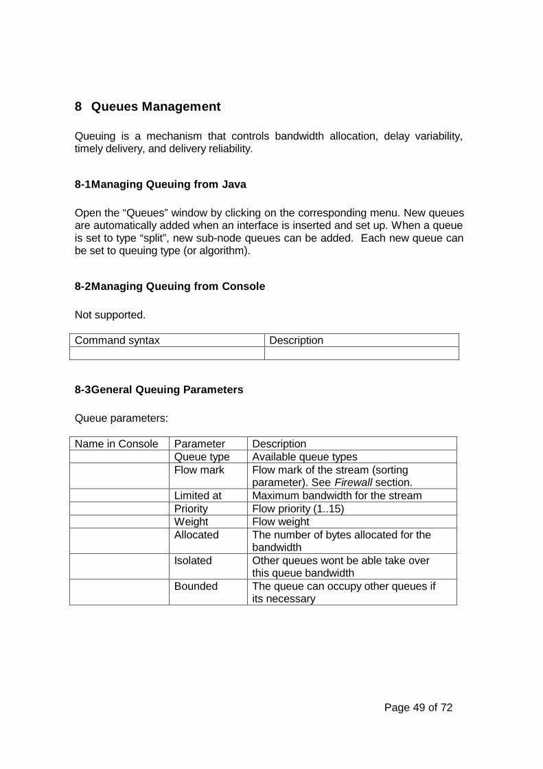
Page 49 of 72
8 Queues Management
Queuing is a mechanism that controls bandwidth allocation, delay variability,timely delivery, and delivery reliability.
8-1 Managing Queuing from Java
Open the “Queues” window by clicking on the corresponding menu. New queuesare automatically added when an interface is inserted and set up. When a queueis set to type “split”, new sub-node queues can be added. Each new queue canbe set to queuing type (or algorithm).
8-2 Managing Queuing from Console
Not supported.
Command syntax Description
8-3 General Queuing Parameters
Queue parameters:
Name in Console Parameter DescriptionQueue type Available queue typesFlow mark Flow mark of the stream (sorting
parameter). See Firewall section.Limited at Maximum bandwidth for the streamPriority Flow priority (1..15)Weight Flow weightAllocated The number of bytes allocated for the
bandwidthIsolated Other queues wont be able take over
this queue bandwidthBounded The queue can occupy other queues if
its necessary

Page 50 of 72
Queue type CharacteristicsPFIFO Packet First-In First-Out – is the simplest queuing algorithm.
The packets are served in the same order as they are receivedBFIFO The same as PFIFO, except that this algorithm is byte-based
but not packet-basedRED Random Early Detection – an algorithm for congestion
avoidance in packet-switched networksSplit This type allows the packets to be sorted by flow mark and
specify the parameters for each such sub-node separately.Each sub-node can be of type PFIFO or BFIFO. It cannot besplit further
RED queue parameters:
Name in console Name in Java DescriptionQueue Type Queue typeBandwidth Queue bandwidth (in bytes/sec)Min Threshold Before this value is achieved no packets
will be thrown awayMax Threshold When this value is achieved the queue
will throw away the packets usingmaximum probability, where thisprobability is a function of the averagequeue size1.
Queue Size Queue size in bytesBurst Number of packets allowed for an
occasional bursts of packets in thequeue
PFIFO queue parameters:
Name in console Name in Java DescriptionQueue Type Queue typeBandwidth Queue bandwidth (in bytes/sec)Queue Size(in packets)
Maximum packet number that queue canhold
1 If probability is denoted by p then consider the following: min <= p <= max, where minis p when average queue size = minimum queue size (p=0%) and min is p, whenaverage queue size = maximum queue size (p=2%).
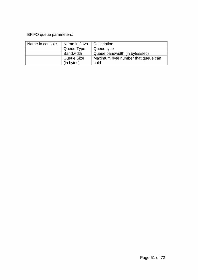
Page 51 of 72
BFIFO queue parameters:
Name in console Name in Java DescriptionQueue Type Queue typeBandwidth Queue bandwidth (in bytes/sec)Queue Size(in bytes)
Maximum byte number that queue canhold

Page 52 of 72
9 Advanced Routing Management
Standard kernel routes are created when adding an address to the router andstatic routes are added by the user. A third type of route is created by softwaredaemons such GateD routing. For exchanging the routing information betweenthe routers, MikroTik™ Router Software supports two interior routing protocols:the Routing Information Protocol (RIP) [Version 1 and Version 2] and the OpenShortest Path First (OSPF) protocol.
9.1 Routing Information Protocol
RIP selects the route with the lowest metric as the best route. The metric is a hopcount representing the number of gateways through which data must passthrough to reach its destination. To enable the exchange of routing informationbetween two routers connected to the same network both routers should haveRIP enabled on the interfaces to the network which connects them. Onlyinformation about kernel routes and routes learned using RIP is exchangedbetween the routers.
9.1-1 Managing RIP from Java
Select the “Routing” menu and the “RIP” menu. Select the icon of the desiredinterface to change its RIP settings.
9.1-2 Managing RIP from Console
Go to the “routing” menu by executing the command with the correspondingname from the base level. Then go to the “rip” menu.
Command syntax Descriptionprint Show RIP settingsexport Export RIP settingsset <interface>[in none|rip1-2][out none|rip1|rip1-comp|rip2][auth MD5|none|simple][metric <value>][passwd <passwd>]
Change RIP settings

Page 53 of 72
9.1-3 General RIP Parameters
Name in console Name in Java Descriptioninterface Interface Interface namein In Incoming RIP modeout Out Outgoing RIP modeauth Authentication Authentication modepasswd Password Password stringmetric Metric Metric used both outgoing
and incoming routes (thismetric is added to existingmetric of route). Positivenumbers greater than 0.
9.2 Open Shortest Path First
OSPF is a shortest path first or link-state protocol. OSPF is an interior gatewayprotocol that distributes routing information between routers in a singleautonomous system. OSPF chooses the least cost path as the best path. OSPFis better suited than RIP for complex networks with many routers. OSPF providesequal cost multipath routing where packets to a single destination can be sent viamore than one interface simultaneously.
9.2-1 Managing OSPF from Java
Select the “Routing” menu and then the “OSPF” menu. Four tabs can be used forconfiguration: “Interfaces”, “Areas”, “Stub Hosts,” and “Virtual Links”.
9.2-2 Managing OSPF from Console
Go to the “routing ospf” menu.
Command syntax Descriptioninterface OSPF interfaces menuarea OSPF areas menushost OSPF stub hosts menuvlink OSPF virtual links menuset routerid <address> Change router ID (if this value is not
set than the router will choose any ofassigned IP addresses)
print Show router IDexport Export OSPF settings

Page 54 of 72
OSPF interfaces menu commands:
Command syntax Descriptionprint [detail] Show OSPF interfaces (you can use
detailed form)export [<filename> append] Export OSPF interface settings (You can
export in a file or append to an existingfile)
set <interface> [up][down] [area <name>][cost <value>][prio <value>][passwd <password>][retr <value>][delay <value>][hello <value>][dead <value>]
Change OSPF interface settings
OSPF areas menu commands:
Command syntax Descriptionprint Show OSPF areasexport [<filename> append] Export OSPF areasset <area> [name <name>][cost <value>][auth none|simple][stub on|off]
Change OSPF areas
add name <name>id <address>[cost <value>][auth none|simple>][stub on|off]
Add new OSPF area
remove <area name or number> Remove area
OSPF stub hosts menu commands:
Command syntax Descriptionprint Show OSPF hostsexport [<filename> append] Export OSPF hostsset <host> [area <name>][cost <value>][host <address>]
Change stub host properties
add area <name> cost <value>host <address>
Add stub host
remove <host number> Remove stub host

Page 55 of 72
OSPF virtual links menu commands:
Command syntax Descriptionprint [detail] Show virtual links (you can do it in
detailed form)export [<filename> append] Export OSPF virtual linksset Change virtual link propertiesadd area <name>neighbor <address>[prio <value>][passwd <password>][retr <value>][delay <value>][hello <value>][dead <value>]
Add virtual link
remove <link number> Remove virtual link
9.2-3 General OSPF Parameters
Interfaces parameters:
Name in console Name in Java Descriptioninterface Interface Interface namearea Area Areaupdown
Enabled Enable/Disable OSPF
cost Cost Cost. Positive number greater than0
prio Priority Priority. Number from 0 till 255passwd Password Passwordretr Retransmit Interval Retransmit Interval. Greater than 0.
Default value is 5.delay Transit Delay Transit Delay. Greater than 0.
Default value is 1.hello Hello Interval Hello Interval. Greater than 0.
Default value is 10.dead Router Dead Interval Router dead interval. If the router
doesn’t receive an answer from theneighbor router during that time itwill regard it as not functioning.Greater than 0. Default value is 40.
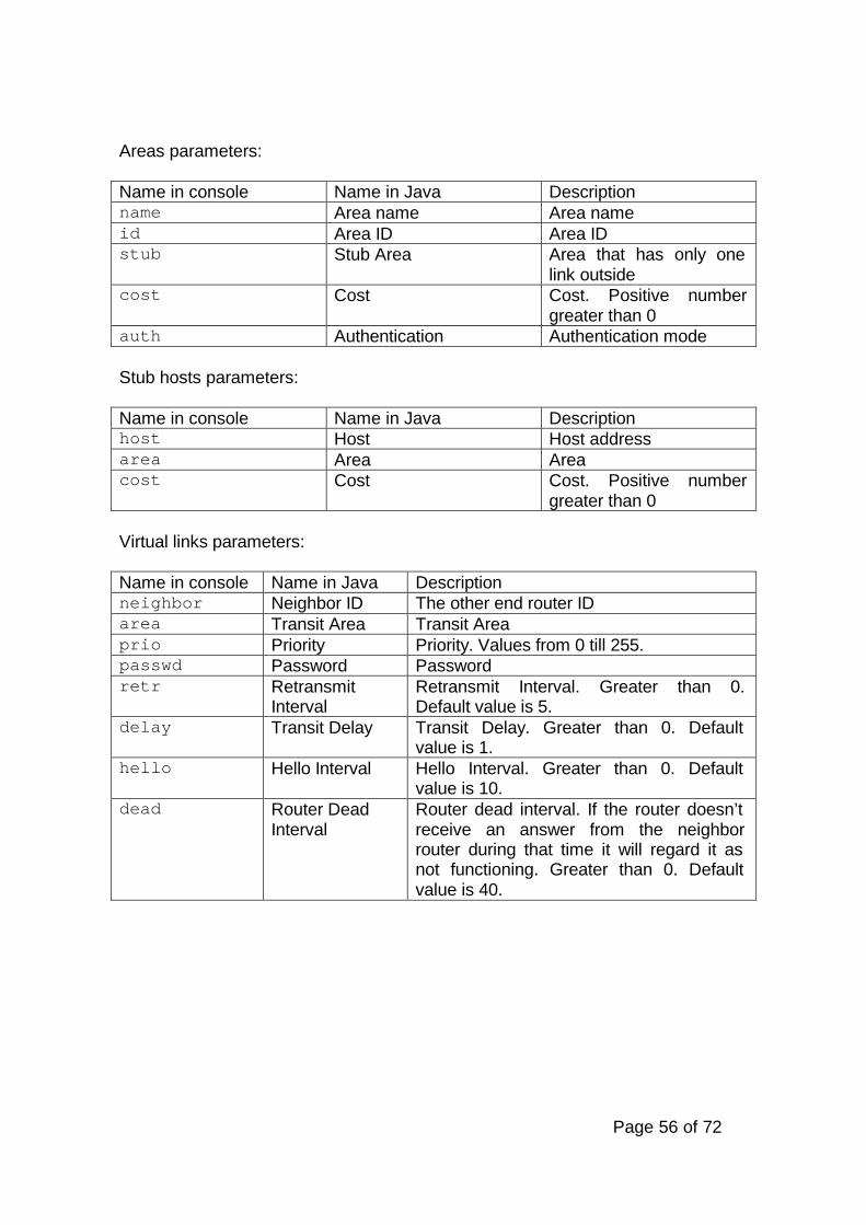
Page 56 of 72
Areas parameters:
Name in console Name in Java Descriptionname Area name Area nameid Area ID Area IDstub Stub Area Area that has only one
link outsidecost Cost Cost. Positive number
greater than 0auth Authentication Authentication mode
Stub hosts parameters:
Name in console Name in Java Descriptionhost Host Host addressarea Area Areacost Cost Cost. Positive number
greater than 0
Virtual links parameters:
Name in console Name in Java Descriptionneighbor Neighbor ID The other end router IDarea Transit Area Transit Areaprio Priority Priority. Values from 0 till 255.passwd Password Passwordretr Retransmit
IntervalRetransmit Interval. Greater than 0.Default value is 5.
delay Transit Delay Transit Delay. Greater than 0. Defaultvalue is 1.
hello Hello Interval Hello Interval. Greater than 0. Defaultvalue is 10.
dead Router DeadInterval
Router dead interval. If the router doesn’treceive an answer from the neighborrouter during that time it will regard it asnot functioning. Greater than 0. Defaultvalue is 40.
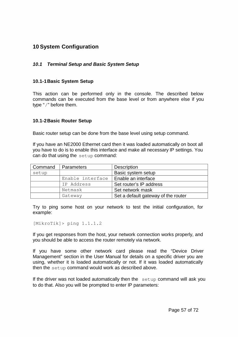
Page 57 of 72
10 System Configuration
10.1 Terminal Setup and Basic System Setup
10.1-1 Basic System Setup
This action can be performed only in the console. The described belowcommands can be executed from the base level or from anywhere else if youtype “/” before them.
10.1-2 Basic Router Setup
Basic router setup can be done from the base level using setup command.
If you have an NE2000 Ethernet card then it was loaded automatically on boot allyou have to do is to enable this interface and make all necessary IP settings. Youcan do that using the setup command:
Command Parameters Descriptionsetup Basic system setup
Enable interface Enable an interfaceIP Address Set router’s IP addressNetmask Set network maskGateway Set a default gateway of the router
Try to ping some host on your network to test the initial configuration, forexample:
[MikroTik]> ping 1.1.1.2
If you get responses from the host, your network connection works properly, andyou should be able to access the router remotely via network.
If you have some other network card please read the “Device DriverManagement” section in the User Manual for details on a specific driver you areusing, whether it is loaded automatically or not. If it was loaded automaticallythen the setup command would work as described above.
If the driver was not loaded automatically then the setup command will ask youto do that. Also you will be prompted to enter IP parameters:

Page 58 of 72
Command Parameters Descriptionsetup Basic system setup
Load driver Load network device driver. You can chooseone of the following: arlan, moxa, ne2k-isa, pc-isa, radiolan
driver io Set input/output port range base address.Can be omitted if device does not use IOports
driver irq Set Interrupt Request Number. Can beomitted if device does not use IRQ. For IRQprobing enter 0
IP Address Set router’s IP addressNetmask Set network maskGateway Set a default gateway of the router
Use ping command as described above to check your settings.
10.1-3 Set Terminal Type
Command syntax Descriptionset [ansi | linux | rxvt-m |vt100 | vt220 | xterm |dumb | rxvt | sun | vt102vt52]
Set terminal type
print Show current terminal typereset Reset previous terminal type
10.2 Packages
Packages are used to upgrade the router or add features. Packages should beobtained from the Mikrotik website. Packages can be FTPed to the router onlyby user “root”. After rebooting the router, the packages will be installed.
10.2-1 Viewing Packages from Java
Select the “System” menu and then the “Packages” menu. Name, version, andbuild numbers of the installed packages are shown under the “Installed” tab.Name, version, and upload time are shown of the uploaded packages under the“Uploaded” tab.

Page 59 of 72
10.2-2 Viewing Packages from Console
In the console installed and uploaded packages information can be viewed in the“sys package” menu by executing the following command:
Command syntax Descriptioninstalled Installed packages menuuploaded Uploaded packages menu
“sys package installed” menu commands:
Command syntax Descriptionset <number>[uninstall no|off|yes|on]
Uninstall package
print Show installed packages
“sys package uploaded” menu commands:
Command syntax Descriptionremove <number> Remove an uploaded packageprint Show uploaded packages
10.2-3 Packages Parameters
Installed packages parameters:
Name in console Name in Java Descriptionname Name Name of the packageversion Version Version number of the packagebuild Build Number Build Numberuninstall Uninstall Will uninstall after next reboot
Uploaded packages parameters:
Name in console Name in Java Descriptionname Name Name of the packageversion Version Version number of the packagebuild Build Number Build Number
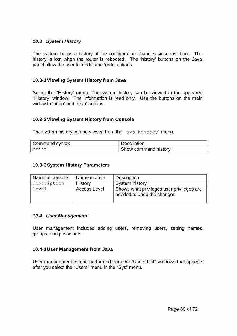
Page 60 of 72
10.3 System History
The system keeps a history of the configuration changes since last boot. Thehistory is lost when the router is rebooted. The ‘history’ buttons on the Javapanel allow the user to ‘undo’ and ‘redo’ actions.
10.3-1 Viewing System History from Java
Select the “History” menu. The system history can be viewed in the appeared“History” window. The information is read only. Use the buttons on the mainwidow to ‘undo’ and ‘redo’ actions.
10.3-2 Viewing System History from Console
The system history can be viewed from the “sys history” menu.
Command syntax Descriptionprint Show command history
10.3-3 System History Parameters
Name in console Name in Java Descriptiondescription History System historylevel Access Level Shows what privileges user privileges are
needed to undo the changes
10.4 User Management
User management includes adding users, removing users, setting names,groups, and passwords.
10.4-1 User Management from Java
User management can be performed from the “Users List” windows that appearsafter you select the “Users” menu in the “Sys” menu.

Page 61 of 72
10.4-2 User Management from Console
Go to the “sys user” menu.
Command syntax Descriptionadd name <name>password <password>group full|ppp|read|write[ppp on|off][desc <description>][server <name>][addr <address>]
Add new user
set <user number>[name <name>][desc <description>][ppp on|off>][group full|ppp|read|write>][password <password>][addr <address>][server <name>]
Change user properties
remove <user number> Remove userprint Show user(s)export Export PPP users
10.4-3 User Parameters
Name in console Name in Java Descriptionname Name Login name - this value cannot be
changed for existing users. Can containletters, digits, “*” and “_”
group Group Indicates the access group the userbelongs to. See the table below foravailable values
desc Description Description for the userpassword Password List box used to change the password
for current user. It conforms to standardUnix characteristics of passwords. Cancontain letters, digits, “*” and “_”
Confirm For password confirmationppp Allow to use PPP Enable to allow dial in use or use the
user name and password forauthentication at the remote host whendialing out
server Server Name Authentication Server Name (empty fieldmeans any server name) for the PPP-

Page 62 of 72
usersaddr Preferred IP
AddressIP address to be assigned to the user’sdial-in client when logged in using PPP.If the remote address is specified in PPPinterface settings then this addressshould match the specified address inorder to enable client to log in
Note: user “*” will be used for PPP as any user
Groups parameters:
Group name in console Group name in Java Descriptionppp PPP Designed for PPP accounts.
Provides only PPP access tothe router
read Read Can only view theconfiguration, but not changeit
write Write The same as “Full”, butwithout permission to add,delete, or change users
full Full Full control
10.5 Change Password
You can easily change password using this special command.
10.5-1 How To Change Password Using Java
In the main menu there is an item “Password”. You will be prompted to enter yourold password and enter new password twice. When you logout and login for thenext time, you must enter the new password. The old password is lost forever.
10.5-2 How To Change Password Using Console
Go to the base level and execute the following command:
Command syntax Descriptionpassword Change user password.

Page 63 of 72
You will be prompted to enter your old password and enter new password twice.When you logout and login for the next time, you must enter the new password.The old password is lost forever.
10.6 System Resources
System’s uptime, total memory, HDD/Flash drive size, CPU type, and CPUfrequency are displayed.
10.6-1 Viewing System Resources from Java
Select the “System” menu and the “Resources” menu. Java gives you expandedpossibilities in viewing the system resources. Under the ‘Monitor’ tab a windowshows the utilization of system’s CPU and memory usage in graphical form.Under the ‘IRQ’ tab, the system’s hardware IRQ’s and their usage are shown.Under ‘IO’ tab, the system’s IO memory ranges used by various devices areshown.
10.6-2 Viewing System Resources from Console
In the console, system resources can be viewed in the “sys resource” menu.There are three submenu there.
Command syntax Descriptioninfo General system informationio I/O port range informationirq Interrupt request information
Submenu commands:
Submenu Command Descriptioninfo print Show system informationio print Show I/O port informationirq print Show IRQ information
10.6-3 System Resources Parameters
General parameters:
Name in console Name in Java Descriptionuptime Uptime Time passed from the last restarttotal memory Total Memory RAM the router is using
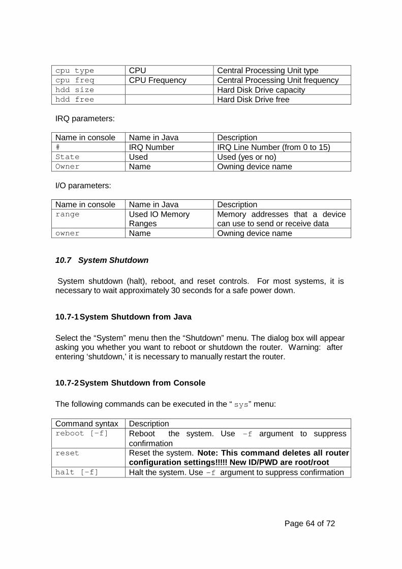
Page 64 of 72
cpu type CPU Central Processing Unit typecpu freq CPU Frequency Central Processing Unit frequencyhdd size Hard Disk Drive capacityhdd free Hard Disk Drive free
IRQ parameters:
Name in console Name in Java Description# IRQ Number IRQ Line Number (from 0 to 15)State Used Used (yes or no)Owner Name Owning device name
I/O parameters:
Name in console Name in Java Descriptionrange Used IO Memory
RangesMemory addresses that a devicecan use to send or receive data
owner Name Owning device name
10.7 System Shutdown
System shutdown (halt), reboot, and reset controls. For most systems, it isnecessary to wait approximately 30 seconds for a safe power down.
10.7-1 System Shutdown from Java
Select the “System” menu then the “Shutdown” menu. The dialog box will appearasking you whether you want to reboot or shutdown the router. Warning: afterentering ‘shutdown,’ it is necessary to manually restart the router.
10.7-2 System Shutdown from Console
The following commands can be executed in the “sys” menu:
Command syntax Descriptionreboot [-f] Reboot the system. Use –f argument to suppress
confirmationreset Reset the system. Note: This command deletes all router
configuration settings!!!!! New ID/PWD are root/roothalt [-f] Halt the system. Use –f argument to suppress confirmation

Page 65 of 72
10.8 System Identity
Set the identification name of the router.
10.8-1 Setting System Identity from Java
Select “System” menu and then “Identity” and enter the router name.
10.8-2 Setting System Identity from Console
Go to the “sys” menu.
Command syntax Descriptionidentity set <name> Set system identity
10.8-3 System Identity Parameters
Name in console Name in Java Description<name> Router Name System identity string is used as human
friendly name for router and also in SNMPqueries. Maximum is 16 characters.
10.9 System Date and Time
View and change the system date and time settings.
10.9-1 Setting Date and Time from Java
Select the “System” menu and the “Date & Time” menu. Changes will bediscarded when the router is restarted.
10.9-2 Setting Date and Time from Console
In the system console date and time settings can be change in two differentmenus. These commands can be executed from the “sys date” menu:
Command syntax Descriptionset time [HH:MM:SS] Set system timeset date Set system date
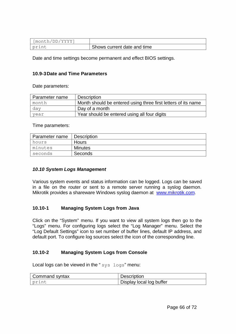
Page 66 of 72
[month/DD/YYYY]print Shows current date and time
Date and time settings become permanent and effect BIOS settings.
10.9-3 Date and Time Parameters
Date parameters:
Parameter name Descriptionmonth Month should be entered using three first letters of its nameday Day of a monthyear Year should be entered using all four digits
Time parameters:
Parameter name Descriptionhours Hoursminutes Minutesseconds Seconds
10.10 System Logs Management
Various system events and status information can be logged. Logs can be savedin a file on the router or sent to a remote server running a syslog daemon.Mikrotik provides a shareware Windows syslog daemon at www.mikrotik.com.
10.10-1 Managing System Logs from Java
Click on the “System” menu. If you want to view all system logs then go to the“Logs” menu. For configuring logs select the “Log Manager” menu. Select the“Log Default Settings” icon to set number of buffer lines, default IP address, anddefault port. To configure log sources select the icon of the corresponding line.
10.10-2 Managing System Logs from Console
Local logs can be viewed in the “sys logs” menu:
Command syntax Descriptionprint Display local log buffer

Page 67 of 72
Global logging management is performed in the “sys logger” menu.
“sys logger” menu commands:
Command syntax Descriptionprint Show global logging configurationset [address <address>][port <number>][lines <number>]
Change global logging configuration
sources/ Log sources configuration menu
“sources” submenu commands:
Command syntax Descriptionprint Show configuration of log
sourcesset <number>[type local|none|remote][address <address>][port <number>][prefix <prefix>][interval <interval>]
Change configuration of logsources
10.10-3 System Logs Parameters
Log sources configuration parameters:
Name in console Name in Java Descriptiongroup Group (Read-only) Name of the log grouptype Logging Type of logging.prefix Prefix Local log prefix is used when local logging is
enabled. Each line coming from this sourceis preceded by a prefix
address RemoteAddress
Remote log server IP address. Used whenlogging type is remote. If not set, default logserver IP address is used
port Remote Port Remote log server UDP port. Used whenlogging type is remote. If not set, default logserver UDP port is used
interval Interval Traffic logs dump interval. Used only forTraffic-Account source. Tells how oftentraffic logs should be dumped

Page 68 of 72
Types of logging:
Type Descriptionlocal When type "local" is used, logs are
stored in local log buffernone When type "none" is used, logs from
this source are discardedremote When type "remote" is used, logs are
sent to remote log server
Global logging parameters:
Name in console Name in Java Descriptionlines Number of Buffer
LinesNumber of lines kept in local buffer. Whennumber of lines in local log buffer isexceeded, lines from the beginning ofbuffer are deleted.
address Default IPAddress
Remote log server IP address. Usedwhen remote logging is enabled but no IPaddress of the remote server is specified(IP=0.0.0.0)
port Default RemotePort
Remote log server UDP port. Used whenremote logging is enabled but no UDPport of the remote server is specified(UDP=0)
10.11 License
You can view and set Software ID Number by executing command “license” inthe “sys” menu in console.
Command syntax Descriptionset <key> Set software keyprint Show software ID number

Page 69 of 72
11 Tools
MikroTik tools include standard TCP/IP tools such as ping and trace-route andalso custom made tools. MikroTik custom tools are designed to assist you inverifying the quality of links – stability and bandwidth. If you have anysuggestion for improving these tools, please suggest it at our suggestion pageon our website.
11.1 Ping
Ping uses Internet Control Message Protocol (ICMP) Echo messages todetermine if a remote host is active or inactive and to determine the round-tripdelay when communicating with it.
11.1-1 Launching Ping Utility from Java
Select the “Ping” submenu in the “Tools” menu. The Ping utility sends fourping messages and displays them in real time in the Ping list box.
11.1-2 Launching Ping Utility from Console
From local console enter the command ping from the base level or us/ping from any location in the console.
Command syntax Descriptionping <address> [psize <packet size>][interval <interval>]
Send ICMP Requests
Ping utility shows Time To Live value of the received packet (ttl) andRoundtrip time (time) in ms.
The console Ping session may be stopped when the Ctrl + C is pressed.
11.1-3 Ping Utility Parameter Description
Name in console Name in Java Description<address> Address IP address for the host you want to
ping.psize Packet Size (optional) Size of each ICMP packet
(in bytes).interval Interval (optional) Delay between messages
(in seconds). Default is 1 second.

Page 70 of 72
11.2 Traceroute
Traceroute is a TCP/IP protocol-based utility, which allows the user todetermine how packets are being routed to a particular host. Tracerouteworks by increasing the time-to-live value of packets and seeing how far theyget until they reach the given destination; thus, a lengthening trail of hostspassed through is built up.
11.2-1 Launching Traceroute Utility from Java
Select the “Traceroute” window in the “Tools” menu. When the trace iscomplete, the output indicates total number of hops to the host andcorresponding TTL values per hop.
11.2-2 Launching Traceroute Utility from Console
Execute the command traceroute from the base level:
Command syntax Descriptiontraceroute <address> [timeout <timeout>][psize <psize>]
Trace route to a host
Traceroute shows the number of hops to the given host address of everypassed gateway. Traceroute utility sends packets three times to each passedgateway so it shows three timeout values for each gateway in ms.
11.2-3 General Traceroute Utility Parameters
Name in console Name in Java Description<address> Trace To IP address of the host you are tracing
route to.timeout Timeout (optional) Response waiting timeout,
i.e. delay between messages(10..1500, default 64).
psize Packet Size (optional) Packet size in bytes (1..5,default is 1).
11.3 Bandwidth Test
The Bandwidth Tester can be used to monitor the throughput to a remoteMikrotik router (either wired or wireless) and thereby help to discover network‘bottlenecks’.
The TCP test uses the standard TCP protocol with acknowledgments andfollows the TCP algorithm on how many packets to send according to latency,
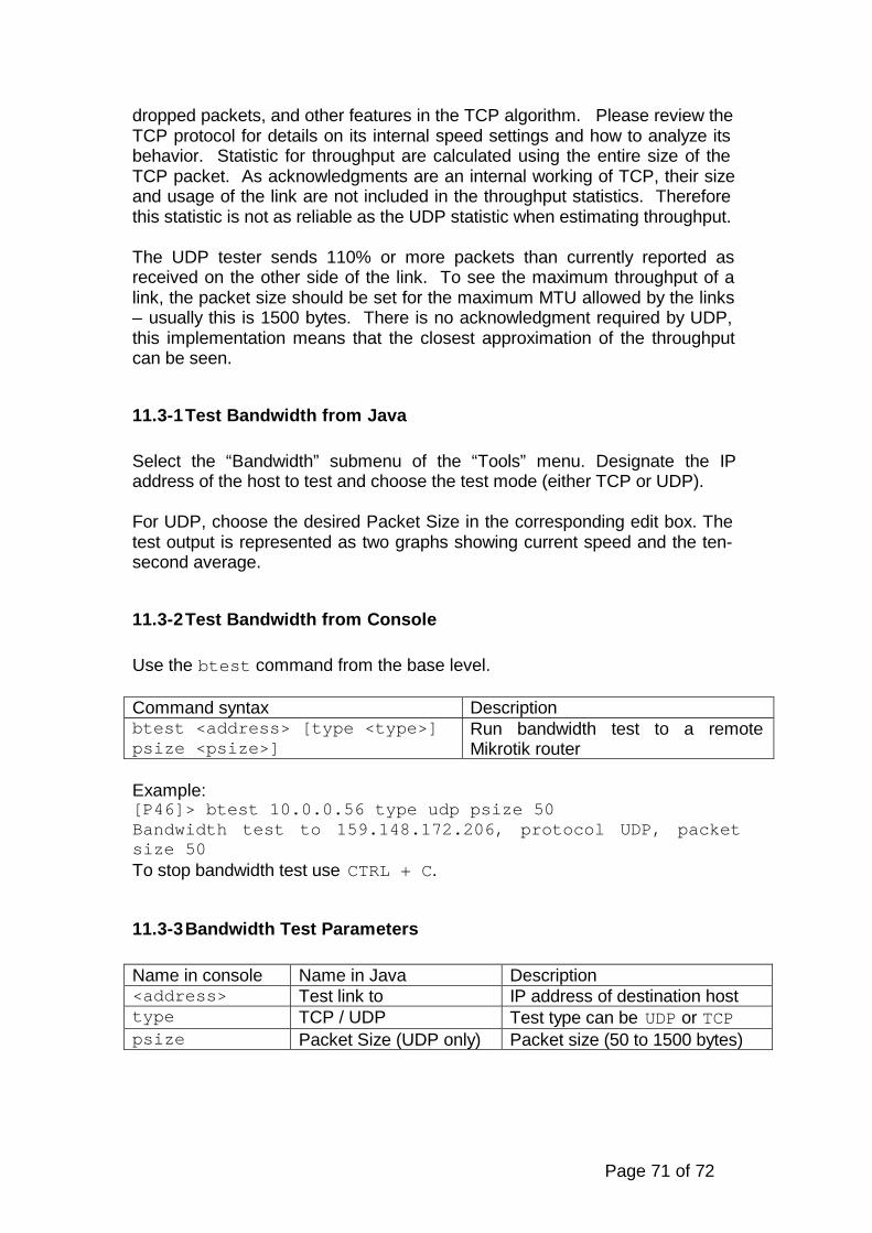
Page 71 of 72
dropped packets, and other features in the TCP algorithm. Please review theTCP protocol for details on its internal speed settings and how to analyze itsbehavior. Statistic for throughput are calculated using the entire size of theTCP packet. As acknowledgments are an internal working of TCP, their sizeand usage of the link are not included in the throughput statistics. Thereforethis statistic is not as reliable as the UDP statistic when estimating throughput.
The UDP tester sends 110% or more packets than currently reported asreceived on the other side of the link. To see the maximum throughput of alink, the packet size should be set for the maximum MTU allowed by the links– usually this is 1500 bytes. There is no acknowledgment required by UDP,this implementation means that the closest approximation of the throughputcan be seen.
11.3-1 Test Bandwidth from Java
Select the “Bandwidth” submenu of the “Tools” menu. Designate the IPaddress of the host to test and choose the test mode (either TCP or UDP).
For UDP, choose the desired Packet Size in the corresponding edit box. Thetest output is represented as two graphs showing current speed and the ten-second average.
11.3-2 Test Bandwidth from Console
Use the btest command from the base level.
Command syntax Descriptionbtest <address> [type <type>]psize <psize>]
Run bandwidth test to a remoteMikrotik router
Example:[P46]> btest 10.0.0.56 type udp psize 50Bandwidth test to 159.148.172.206, protocol UDP, packetsize 50To stop bandwidth test use CTRL + C.
11.3-3 Bandwidth Test Parameters
Name in console Name in Java Description<address> Test link to IP address of destination hosttype TCP / UDP Test type can be UDP or TCPpsize Packet Size (UDP only) Packet size (50 to 1500 bytes)

Page 72 of 72
11.4 Ping Flood
Ping flood sends ICMP (Internet Control Message Protocol) echo requests toa remote host in the same manner as the ping utility but it sends the nextrequest as soon as it receives a reply.
11.4-1 Launching Ping Flood from Java
Select the “Flood Ping” submenu in “Tools” menu. Flood ping shows sentpackets percentage (from the given number), received packages percentage,minimum, average and maximal Roundtrip Time of the packages.
11.4-2 Launching Ping Flood from Console
Command floodping should be executed from the base level with thefollowing parameters:
Command syntax Descriptionfloodping <address>[psize <size>][timeout <time>][total <number>]
Launch flood ping
11.4-3 Ping Flood Utility Parameters:
Name in console Name in Java Description<address> Ping to IP address of destination hostpsize Packet Size Size of each ICMP packet (in bytes)total Number of
PacketsNumber of ICMP packets
timeout Timeout Time after which in the packet isconsidered lost in case of no response(in ms)


![MikroTik™ V2.0 Router Software Technical Reference Manual · [MikroTik]> ip firewall export test [MikroTik]> ip nat export test append The file can be accessed now by ftp (only](https://img.dokumen.tips/doc/110x75/5c8f570409d3f2a2628c20fb/mikrotik-v20-router-software-technical-reference-manual-mikrotik-ip-firewall.jpg)


![Router [Mikrotik]](https://img.dokumen.tips/doc/110x75/558e43221a28ab8e668b45ff/router-mikrotik.jpg)