Embed Size (px)
Citation preview
(.
FOR THE
MIDGET AND SPRITE948 e,c,
--
- --- I-----~-,------,
~~ --, - .".
" .• •
Iss ued by:
BRITiSH LEYLAND SPECIAL TU NING DEPART MENT
ABINGDDN -DN -THAMES • BER KSHI RE· ENGLAND
C- AKD 1D21C
ENGI~~ NO PREFIX 9C geG
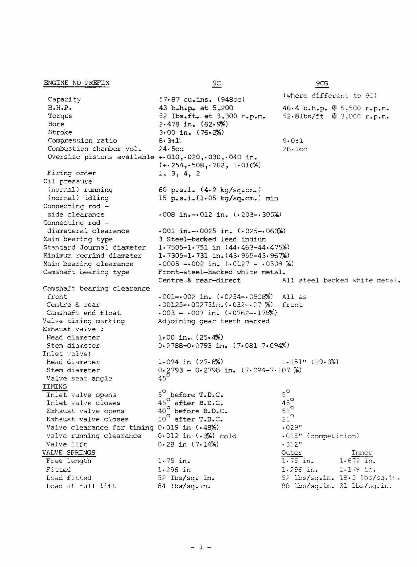
·001 in.-·0025 in. (.025-.063%)3 Steel-bac::ked Lead. indium1·7505-1·751 in (44.463-44.47~)
1·7305-1·731 in.(43.955-43.96~)
·0005 -.-002 in. (·.0127 - .0508 %)Front-steel-backed white metal.Centre & rear-direct All steel backed wru te me t c ;,
·008 in.-·012 in. (.2C3-.30~)
CapacityB.H.P.TorqueBoreStrokeCompression ratioCombustion chamber vol.Oversize pistons available
Firing orderOil pressure
(normal) running(normal) idling
Connecting rod -side clearance
Connecting rod diameteral clearance
Main bearing typeStandard Journal diameterMinimum regrind diameterMain bea~ing clearanceCamshaft bearing type
57·87 cu. ins. (948cc)43 b.h..p. at 5,,20052 Ibs.ft. at 3,300 rvpvn,2·478 in. (62·~1
3·00 in. (76.2%"8·3,;].24·5ee+.010,·020,.030,.040 in.(+.254".508,.762.1.016%)1,3,4,2
60 p.s.i. (4.2 kg/sq.cm.)15 p.s_.i. (l.05 kg/sq.cm.) min
(where differc~t to
46·4 b.h.p. ® 5,50052·81bs/ft ® 3,000
9·0:126·1cc
r.p.m.r.p.m.
1·00 ino< (25.4%10·2788-0·2793 in. (7.C81-7.094~)
1bs/sa.in.
, - ~~ ."- • J. ';' IT.•
Inner1·E72 in.
(compeLi:.io:;)
All asf ront.
1· 75 in.1· 296 Lr, ,52 1bs/sq.ir.. 13·': Ibs!sq.i:,.88 Ibs/sq.i~. 31
_0,45°-5,1"
n°·029"• C15". 312"Outer
1·151"(7.094-7.107 %1
1·094 in (27.~)
0-2793 - 0.2798 in.45
0
1·75 J.n.
o5 before T.D.C.45
0 after 8.D.C.o
40 before B.D.C.100 after T.D.C.0.019 in (.41l)l10·012 in (.3,%) cold0·28 in (7.14"''')
.001--002 in. (.0254-.0SJ~)
• 00125-· 00275in. (·032-· 07 %)·003 - .007 Ln , (,0762-· 178%0)Adjoining gear teeth marked
1·296 in52 Ibs/sq. J.n.84 Lbsv'eq s Ln,
Lead fittedLoad at full lift
Exhaus-t va.lve opens
Cent:::.-e & rearCamshaft end float
Valve ti~ing markingExhaust vAlve:
Head c.iameterstem diameter
Ln l e-; veIve .Head diameterStem diameterValve seat angle
THlINGInlet valve opensInlet valve closes
Camshaft bearing clearancefront
Exh3list valve closes,Valve clearance for timingvalve runrU-~g clearanceValve lift
VALVE SPRINGSFr-ee ler.gth
- 1 -
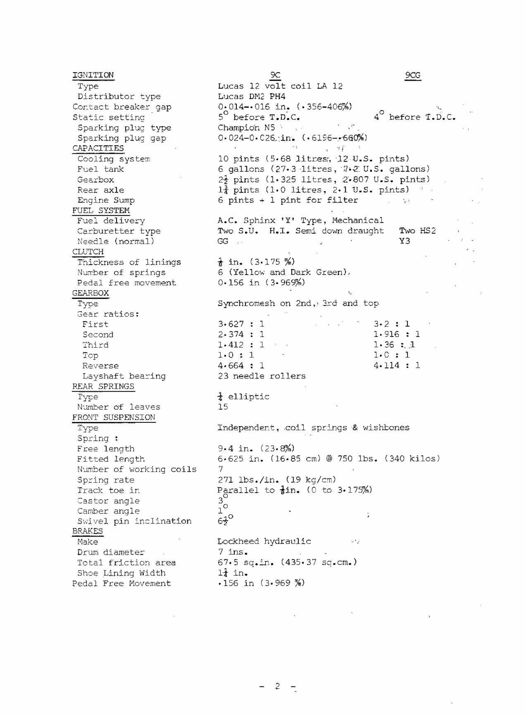
10 pints (5· 68 j.Lt.cesr, '12 U.5. pints)6 gallons (27-3 -Lt t res , -rz-.·z U.S. gallons)2t pints (1·325 litres, 2"·B07 uvs , pints)Ii pints (1·0 litres, 2.1 u.s. pints)6 pints + 1 pint for filter ', '
3·627 , 1 3- 2 • 1-2·374 - 1 1·916 • 1• -1· 412 , 1 1·36 :. ,11·0 , 1 1.G - 1-4·664 • 1 40114 • 1- •
23 needle rollers
Synchromesh on 2nd" 3rd and top
A.C. Sphinx 'Y' Type, Mechani c a lTwo S.U. H.I. Semi down draughtGG
T. D. C.
Two HS2Y3
9CG
40 Defore
-, i
9CLucas 12 volt coil LA 12Lucas DM2 PH40·014-·016 in. (·356-40$%)° -5 before T.D.C.Champidn N50.024-0.C2Q:in. (.6196-.n6~)
tin. (3-175 %)6 (YellO'...· and Dark Green),0·156 in (3.969%)
-t elliptic15
ReeL" axleEYlgine Sump
FUEL SYSTEMFuel deliveryCerburetter typeNeedle (norrna'l )
CLUTCHThickness of liningsNUTber of springsPedcl free ITovement
GEA...l:t.BOX
TypeGear ratios:FirstSecond'l'birdTopReverseLayshaft bearing
REAR SPRINGSI'ypeN~er of leaves
FRONT SUSPENSION
IGNITIONTypeDistributor ~ype
Co~tact breaker gapStatic settincSparking plug typeSparking plug gap
CA?ACITIESCooling s ys t.emF'ue I tankGec.rbox
fndependent , .ccd.I spr.mqs & wishbonesSpring :Free lenathFit.tec lengtr,N~Tber of working coilsSpring rateTrack toe in- ~ 1-~2S ror ang eCamber angleS,d vel pin inclination
BRA..KES
nakeDrum diameterTotal friction areaShoe Lining width
Pedal Free Movement
9·4 in. (23.8',%)
6·625 in. (16.85 cm) @ 750 Ibs. (340 kilos)7271 Ibs.!in. (19 kg!e~)
Parallel to iin. (0 to 3.17P~)
3°1°
6+°Lockheed hydraulic .','7 ins.67.5 sqc Ln, (435· 37 sq. em. )It in.·156 in (3.969~)
2
9C- <KG
Bet r e r v typeGen e re tor' • • -<=- - ~
Cut ting in s peedMa x i ;1"'.lm ou t pu tSta ~ t i ~g motor : y peCor-t r o l box type
WHEE: · ;''':-./0 TYRE DATA
BT 7A , 1 2 v o ltLucas C39 OV2 wi t h t acho dr i ve1 , 050 to 1 , 200 r . p. m.13· 5 vo l t s 19 amps .Lucas M35 GlLuc a s RB 106 2
~ · 20 - 13 Tube les s2
: 8 Ibs./sq . ~n . (1 - 27 kg . ::m2 )~ O Ibs . / sq . ~n . ( 1 ·41 k g · e m )1 3 x 3. 5D s t ee l d i s c , 4 s tud f ixi ng
11 ft . 51-i n . (3·49 m)
5 f t . 9 in . ( 2 ·03 m)
5 .i.n , (0 · 1 3 rr.)
4 f t . 5 in . (1 · 35 m)3 ft . 9i i n . ( 1· 16 m)3 ~t . at i~ ( 1· 14 m)31 f t . 6 in (9 . 60 m)
we ight 1 3 c ....-t , ( 6EC k g ) .
re e. :::-f ron tPr-e s sure s :
Ty ... .:. <:.; 'C.&'>-- _....~-
Wh e '2 1 -; ypeTORQUE S!?ANNER DATACylinde~ he ad st~d nuts 40 lb/ f t . (5·5 k g/m)Cop~ect ing rod ~ig end bolts 35 lb/ f t . (4 · 8 kg/m )Mai~ bea r i ng s e t s c r e ws 60 Ib/ f t . (8·3 kg / m)F l y .·!he e l set s c r s v....s 40 I b/f L (5 . 5 kg/m)Rockc ~ bracke t nuts 25 Ib/f t . ( 3· 4 kg/ m)Gud~ec~ Pi n C la~p scr ews 2S Ib/ft . (3 . 4 kg/ ml
GENERAL DI~SIONS
Overa ll l eng t hWhee l=.:=.seMin~~~m ground c l ear anceOve r a l l "oJid t hTr- eck ( f r ont )'rr-ecc :: rea r)'rurruno circl eAocr c x i ma c e ke r b s .roe~ ..._ ... . . _ ...<0"". _ _L-
WARNI:~G
These car s have had a consider able amount of use b y now a~d i t i s i~~crtant
t o en5~re tha t ~he ~hDle of t he car i s in safe anc sati s f actor y conditio~ Cc£o rp.carryi ng cut a~y ~uning .
F~ll informction on t he corr ect maintenance a nd repa~r of t hese ccr s i s c ont.at r.ed a.r: wor k shop Manual Part No. AKD 4884 01k. . I Sprit e! 1 o r AKD 4021)) (:. 1).; .
I I / II I Spr i t e ) ~r. j Mk . I / I I Mi dg et) .
- 3 -
Introduced in 1958 with t.wa.n Ii" s.u. Ce.rburet.t.er-s the Sprite Mk.Iutilised compon~nts from the then current A35 and was identified by theengine prefix 9C.
In 1961 the body wa s restyled and commonised with an MG Midget series(Sprite ?&.II - VQdget Mk.IJ. The power unit was uprated in this application ~ith a slightly better camshaft (AEA 630) using three camshaft bearings,flat top pistons and larger inlet valves in an improved cylinder head. TwinIi" s.u. carburetters were standard. The gearbox was also improved wi t hcloser ratios and gears on needle rollers in place of bushes, all identifiedby the englne prefix 9CG.
ENGINE TUNING 9C UNITS
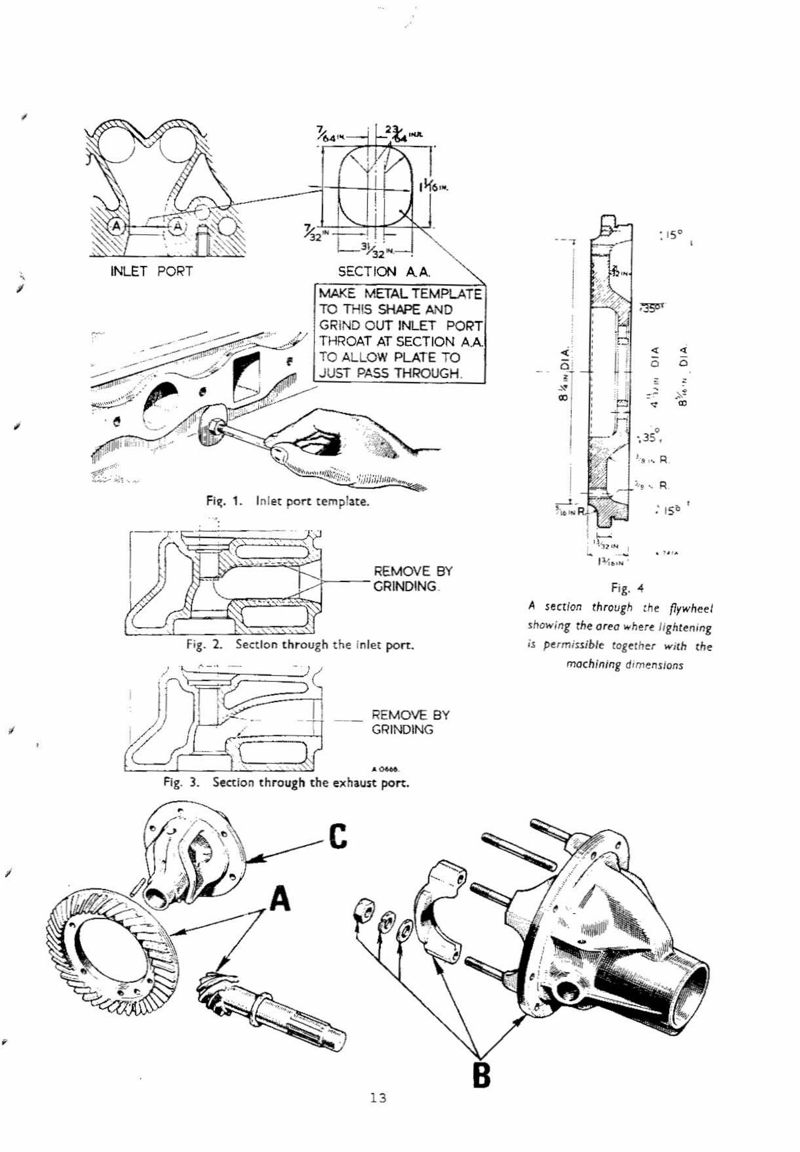
An increase of some 2 B.H.P. can be obtained by general attention tothe cylinder head and port polishing. Lightly grind and polish the exhaustand inlet ports throughout. They should not be ground out S0 heavily thatthe shape or' valve choke diameters are impaired.
Match up the exhaust rraDifold ports with the cylinder head ports byqri.no i.r.o , Grine. out the inlet bore 0= the rnandfc Lc to It" diameter atthe c yl Lnder- head face by g.:-inding out right through to this diameter tomatch the carburetter bore, and then polish.
Do not grinc out the co~bustion spaces as these are already quite cleanand partly machined! but remove any frazes and lightly polish all over. A~y
enlarge~ent araunG the combustion walls nay cause the cylinder head gasket tooveLlap and destroy the efficiency of the seal. Also the compression retiawill be lowercd and the tuninc will be ineffective.
A further increase can be obtained by alteration to the irclet/exhaustports. Grind cut and enlarge at the inlet port neck.
Make up a sheet-metal terrplate to the dimensions given in Fig. 1 andfQstc~ it to a long bolt so that it may be used as a gauge when grindingout the inlet ports.
Be very careful to grin6 the inlet port throat central,be~~een the pushrod holes, as the waLl. left is only ·086" thick. Ease off the port by gri::1cr.nq at the valve guide boss 2.Ld the opposite port 'd2.11 bend as depicted ir. Fig.2.
Erl2.rge the ek~aust ports at the ber.ds by grinclng at the valve guideboss aDa the opposite port ~all as sho~~ in Fig. 3.
WarD2-liO When carrying out aj t.er-atd.ons to the shape of the valve ports, t.t:eresponsibility for any damage that may occur must rest with the owner or theperson authorising the alteration.
A~ternatively a polished and modified cylinder head can be purchasedincludir.g the above modifications, under Part No. C-AHT 87. This head ~ill
also increase the compressicr: ratio to 9:1, and atreecy r t t tec wt th new ve rvesand """'1-·-','" spr-Inos,-", ."_.' - ,,' . ,-'
car-bure t t s rB.T.D .C.
needles C3G, or Gr,) v.t thout
- 4 -
ai::- crearner-s ,
Flat t op pi s tons 12Ahead modi f i ed as above.
187 wil l give 9· 3 : 1 coocpression ~~th t he s ta~c =~d
Se t i gni t i on t o 30 B.T . D. C.
vmen fit t ed wit h t he modi f ied head C- AHT 87 t he compr ess ion r a t i o ~i1 1
incr eas e t o 10· 6 : 1 . Set i gni t i on approximat e l y 2° B. T. D. C.
A polis hed and modifi ed ve rsi on of t he l a rger va l ve 9CG head C- AHT 90coul d be f itted wi t h the f la t top pi s tons , compres s i on would be 9· 7: 1.Ig~ition and car bur e t t e r need l es as above .
Af t e r car r ying out thE e ar lier stages of tune, edditio~al irnprove~e~ts
c an be ob t ainec by f i tti ng the f o l l owi ng parts :-
Par t Nc . ~-2 7H 7766
i rres pect i ve of c yl i nder
Va l ve s prings 8 of fCamsha f t
oTimi ng , I n l et; opens 16 B. T.D .C . , c l oseso
Ex..l)au~ t opens 51 B.B. D.C " c losesVa l ve l i f t - · 312 i n. ( 7· 94%)Di s t r i bu tor (us e with c amshaf t BSG 229 )
Ret a in the s t a tic ig~ition at 10 B. T. D. C.head .
Par t No .Part No .
56° A.B . D. C21° A. T . D. C
C- 2ASSG
(Ri c her )
Ca r bur e t ter needles GG Part No . AUD 1211 vri ~h air c lea~er5
GM Par t No . AUD 1217 less a i r clEa~er 5
Over 9· 5: 1 compr es sion use t he r i cher nee d l e ~8 Part No. AUD 1149.
If t he i n l et manifold i s po l i s hed out t o acce~t t he It" H5 2 carbuc~ -::t e J::'s
(Std . on 9CG) ~he ne edles ~ould be
V3 Pa r t No. AUD l ~l l
V2 Pa r t No . ADD 141J
USE cyl incer he ad ga ske t C- AEA 64 7 in a l l c a s e s of raisec compress~o~
ex=ep~ wi t h r ace cyl inde r ~ead C- AHT 222 on whi ch gaske t C-F~~ 188 shou l dbe used .
ENGI~E TUNI NG :JCG
This power ~~it has 2 cylinder head wi t h i nc r e ased inl e t va l ve di~~ete~
and port sizes .
C- AHT 90 i s a po l i s hen and modi f i ed versio~ ~vai lable f o r immedi at e r e placement , ~nich again i s compl e te wi th va l ves , spr~r.g s ar~ ccl l e t s e t c .
As the fl :l:' topi nc r ecs ed to 9· 7 : 1 .needles .
pis t onsS t a tic
are s tanda rd t o t hi s ~odel corrpres s i on wi ~ l bei gnition should be 2° 3 . T.D .C. ~ith sta~d2rd
As t his rrode l has AEA 311 and AEA 401 va l ve spr i ngs as s t anda rd ~r.~ r eVr~~e is grea t e r than 9C uni t s (SEE SPECIAL ITE~5 Val ve Spr ings ), L~e ca~shaft
i s AEP. 630 wi t h i ncre ased l i f t and e xhaus t va l ve Fe r i od (Se e Da t a ) .
Camsha f t SSG 229 and Distribut or C- 27H 7766 (de t a i l s cDCve ) wi l l pr ovi dei r.cr eased po~e~ and r . p . m.
AT THIS POI]\,T THE ENGINE SPECI FI CP.TION BECOnES SI MI U .R
~~UST SYSTEM
A special tuned exhaus t sys tem is avai l ab l e whi ch wil l ,g i ve an incre2s eof scme 2 t o 3 B.H.P . acc o r di ng t o the tuni ng condi tion i t i s u~ed wi t h . I tmay be lised with any t uning condi tion .
The system consists of :F~ont Manifold (inc l uce s c l i p C- k4A 5450)E~~aust pipeSi l enc e r a s s e mbl y (includi ng c l ip AHA 5450 )
Pa r t No .e- AHA 5448C-~. 5449C- ARA ' 135
Fo" =ac i ng a ppl ications us i ng l a r ge c a rbur e t t e r s , l a r ge valve heads , e tc .the ms xi mum ext r ac t o r man i fo l d C-AHT 11 should be fi t t ed .
VALVE SPRINGS
(a) The 9C uni t wi t h s t andar d camsha f t and s t anda r d va l ve s prings wil l haveva l ve -c r a sh occur at 6 , 100/6 ,300 r .p .m.
(b ) ,men us i ng t he compe t i tion c amsha f t Pa r t No . SeG 229 and special va lves pr i ng C- 2A 950, valve bounce will a l so occur ~t a pproximate ly 6 ,100~o 6,300 r . p .m .
(c ) The competi~ion camsha~t Part No. SSG 229 can also be used with t hes tanda r d va l ve springs , when valve bounce wi l l oc cur at 6 , 300 t o 6 ,400 .
(d) The va l ve Sear and dri,e e r e saf e ly stres s ed t o mai ntain t he above~orrdi tions ( a) , (b ) a nc (c ) . I f : howeve r , f o r very special competitionp~poses . i t i s desi~ed to r ais e t he valve bo~~ce pos i t i or. t o 6 ,700 r . p. m.i t can be done b y us i ng outer va l ve s pri ngs Pa r t No . C- 2A ~50 and f i t t i nge xt r a i nne = va l ve s pring s Pa r t No . AEA 401 . New t o p and bo t t om spr i ngcel l ars AEA ~0 2 and C- AEA 4 32 mus t be f i t ted f or t h i s cond i t i on . Tcfi t the bo~tom co l l ar C-AEA 432 i t will be ne ce s s ary t o spot f ace thes 8 a l l c a s t rec e s s e s on the top of t he cyl i nde r head , a round the valveg~ides t o a diamete r of ·8 75 m. ( 2 2. 22 %) in or de r tha t t he co l l ar s~i l l drop in and s ea t s~~arely. The dep t h of t he s pot f ace shoul d be3/ 32 i n . (2 ·38 %) belo~ t he ou t e r va l ve spr i ng f ace .
(e ) The va lve bounce pos iti on can be f urthe r r aise= t o 7,OCO =. p. m. i f t hee xt ra i nne = valve s pric,gs and colla rs f itted as explai nee i n ' d' wi tht he standa rd outer va lve spr i ng A~~ 311.
This arra ngement using bo~tom co l l : r AEA 403 (not C- AEA 432) i s thestanc~rd 9CG ar r angement .
I t is advi sed t hat t he 2c~ve va l ve spring re-ar rangements be used onlyf o r s pec i a l compe ti t ion pur?~ses , i f used for 2verydcy c onditions the e~gi~e
part s rea y ha ve a s ho r t e r se~~ice l i f t. The valve s prings wi l l no t neces s cri lygi ve ~, i ncreas e in brake-h~r5e-power , c ut will extend t he sa~e horse-po~er
up to ~ highe~ =. p. m. Thi3 i s someti~es useful irr enabling a l owe r r ear axler a t i o t o be reta i ned , and still main t ain t he same ~aximum speed . wit h i nc r e a s e dpower of acce l er a t i o n.
Standar d or competit iG~ c amshaf t s may be us e d , the valve gear s t r e s sesbei~g least wi t~ t he compe t i t i on c ams haft s .
- 6 -
VA.: ;vt. GEAR
wn en pr e pa r i ng units f o r competi t i o n t he i deal rocke r g e a r t o use isf ~c~ t he Coope ~ ' 5' s e r i es . Rocker ] 2G 1221 i~ ligh t e r wi t h gr e e t er s t rengttbe t. requ i r e s new adjus t L"1g s c r ew AD; 16 7 and Iockr.u t; n ,iN 6CS: . Sf-ef t AEG 399has t he loca~ ing hol e ~~ved i n one pillar requi=ing a dri l l ed p i l la r fo~ theo i l ~cy.disFense fti t h one ~ tar.dard pi l l a r . The l o c a ting scr ew 12G 1926 pi l la r$ho~ lc ~e I.cv eC to coi nc i de ~ith t he ~~aft locat~on . The r ockers s hould bes paced by us ing dis t ance t ubes C- AEG 392 i n place o f t he co i l s prings .
EXHA.lJST VALVE
whe-n r ep l aci r.g va l ve s in s t anda r d 9C and 9CG he ad o r C- AHT 87 and C-AHT 90cy l i~c cr he ~d s , us e ONLY AEA 400, KE 965 ' S t e l l i t e ' f ac ed .
DUP LEX 'l'I MIKG GEARS
The increased s t r e s s es c r ea t ed by higher l i f t c ams , s t ronge r val ves pr i ngs p t e • . r educe s the wo~k ing l ife of t he standard s ing: e r ow timL~g
ch~ i" . Fo ~ e l l compe t i t ion o r hi~hly t uned ~~~ ts the Dupl ex cha~~ s r.ouldbe fi t t ed us i ng Kit C- AJJ 3325, ~hich cont a i ns a l l necess a ry pa rts a nefi ~~ing inst~c tions _
CRANKSHAFTS
CcrnDet~~ ion crapk5~ofts ~ave been avail~le previo~sly C- AEA 4C6 i~
t~tter mater~c l and C- AEA 461 Nit r i ded .
C-AEA 461 had eight s~~d ~l~n~e an d rec~i~ed t he c ent r e mUkn ~ccP~~r.q
to c l ea r the webs . St ocks of these type s a r e now e xha us ted .
The Le t e s t, c ompe t .L c i .cr, c r- enkahef t; C- AEA 792 i s i n i mproved mate r i a l andTc; f t r-i ded , it is a di r ec t r ep l ac emen t of the stand ar d ":ypes or C- AEA 406 .
BALANCI NG
Whe r e un ::' t s ar e prepa r ed f o r ma xi mum output; i t is ess ent i a l t hat ther ote t inq ess err.okLes a r e f u l l y ba l anced i.e. c r anks har t , f Lywhe.e I and c lutchc5s~~~ly . Standar d c r~rkshafts c~~ t hen s a =e ~o 6 ,5CO cFm the C-A~. 7S2may exc e ed 7 ,~OO r pm while the F/ J C- AEA 461 ha s e xc eeded 8 , 500 rpm. Re~ ~ound c rar~sh~:ts a re cot recow~e~~ec fo r f~rf~~nce wo~k . but if :'0
e l ternativ~ i~ dvai 1a~le t he =r arkshart ~st be =e-ba l a nced afte~arc $ .
Ni t r Ldod a h a f t,o may accept · 010" u nde r oLze a nd t uf t rided · 0 20" unce r s I ze~~lhcut prc=~s sir. ~ ugain . but THIS CAJ~ NEVER BE DEFI NITE.
The crenk shej t alene does no t limi t rpm (as suming s u i t abl e cam , val veso=i ng , carbc~e tter ar r cr,gement s . et=.) . The s t a ndard c la~p bo l t t y pecop~ecting r e ds are ~r.sui table fo~ sE riou~ co~petition ~ork . whe r e f~l ~y
floa ting gudg~on pins ar~ rods a r e ~ch be t t e r .
"- , -
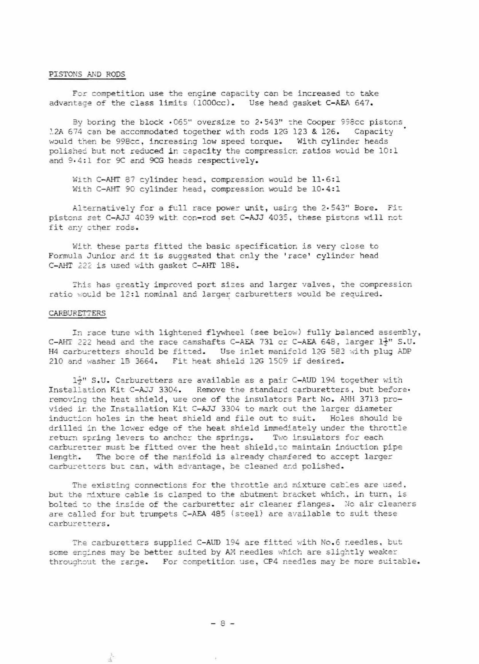
PISTONS ~JD RODS
For competi t i on use t he engine capacity can be i ncr eas ed t o t akeadva~toge of t he c lass l i mit s ( l OOOcc) . Us e head gaske t C-AEA 647 .
By boring the block · 06 5" o ver s i z e to 2 · 54 3" t he Coope r 998cc pis t ol' s .;.2A 6 74 can be ac commoda t e d together with r ods l 2G 12 3 & 126. Capac i t yw~uld t hen be 998c c , incr eas ing low s peed torque . Wi t h cyli nde r headspolish~c bu t no t reduced i n c epac i t y t he compr ess i cr. r a t i os ~~uld be 10 : 1and 9 ·4 :1 fo r 9C and 9CG heads r espective l y.
Wi~h C- AHT 87 cyl inde r he3d , compression would be 11 · 6: 1With C- AHT 90 cyl inder he ad , compression would be 10·4 : 1
Aice r netuve r y f or a f e l l race powe r unit , usir.g the 2 · 54 3" Bore . F"i tpistons set C- fJJ 4039 wi tt c on- r od set C- AJ J 4035 . t he s e pis t ons wi l l notf i t any ct~er rods .
Wit~ t he s E parts f itted t he bas i c s pec i f i c a t i on i s very c lose t oFormula J uni or a~c it i s s~gge s ted tha t onl y the ' r ac e ' cylincer he adC- AHT 222 i s used wi t h gaske t C- AHT 188.
ThiE has g r e a t ly improved port s i zes a nd l a r ge r va l ves , ~he compr es s i onrat io ~o~ld be 1 2 : 1 nominal 2nd la rge~ carburette~ s woul d be ceoui red .
CAF.BURET?ERS
I n r ece t une wi t .hc - xsrr 222 he ad and t heH4 carb~ :-e tters s hoe l d210 an d was he r 23 3664 .
l i gh t e ned flywhee l ( s ee belo~ ) f ully ba l anc ed ass errb l y ,r ace c ams haf t s C- P-.EP. 731 c s: C- AEA 648 , l a r ge r I t " s .U.be fitted . Us e i~let mani=c l d l2G 5E3 ~i th pl ug ADP
Fit he a t shi e ld l 2G 1 509 i f des i r ed .
1-1" S . U. Carburet t ers ar e availab l e as a pa i r C- AUD 194 t oge ther wi t bInstal ~ a tion Kit C-AJ J 3304 . Remove t he standar d carbur e t t e rs . but be r ors ·remov~ng t he hea t shi e l d , us e one of t he insulat o r s Part No . AHH 3713 pr ovide d i ~ t he I ns t a l l a tion Ki t C- AJJ 3304 t o mark out t he large~ di ame t e rinduct~on holes i n t he heat s hi eld a nd f i l e out t o suit . Holes s hould b edr i l l e d in t he lo~e~ edge of t~e heat shield i rnme di c t e l y under t he thro~ tle
retu~ spr i ng l eve rs t o anchcr the s prir.gs . T~o i~sulator~ f or eachcarburet ':er mus t be f itted ove r t he heat shie1d , ~o maint ai n i nduc t i on pi pelengt~ . The bc~e of t he nanifold i s already chamfered t o ac cept large~
carbu~et ~ers b u t c an, with advantage , ~e c l e aned a~d po l ished .
The e xisting connection~ f or t he t hrot t l e ar.d mixt ure cat: e s are us ed .but the ~xture cabl e is cla~ped t o the abut men t bracket Which , i n turn , i sbal tee ~o t he ir.s ~ je of t he car burette = a i r cleaner f langes . ;~c ai r cleaner sar e cal l ed f or but t rumpe t s C- AEA 485 ( s~ee l ) a r e avai l abl e t o suit t hes ec a r bur c t ters .
T~e car bur e t t er s s uppliec C- AUD 194 a r e f i t t ed ~ith No .6 r.eedles , b~t
some er.g~nes may be be t t er s~ited by ~~ r.eedl es which a r e s lig~':ly weak2~
throug~o~t the rar.ge . Fo r conpet i t ion us e , CP4 need l e s may be mor e s~i~able .
- 8 -
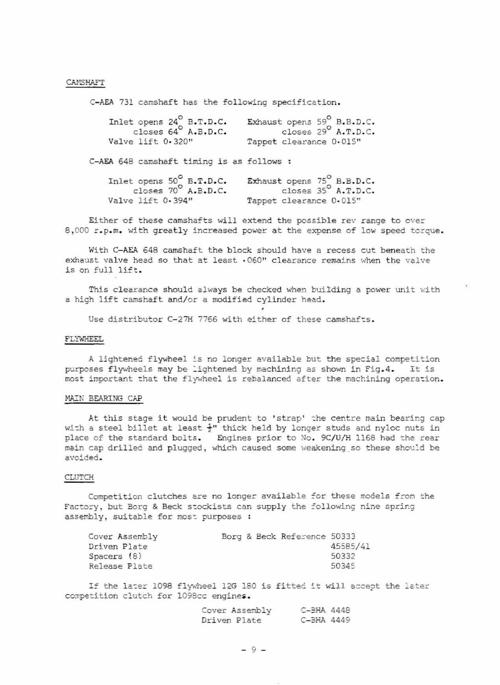
CAHSHAFT
C- AEA 731 camshaf t has t he f o l l owing s pecifi cation .
I nl et opens 240 E.T. D. C.o
c l os e s 64 A.B .D. C.Valve l if t O· 320"
oExhaus t opens 59 B. B. D. C.clos es 29° A. T. O. C.
Tappet c l earance 0 ·01 5 "
C- AEA 648 c a ms ha f t t i ming i s as f ol l ows :
oI nlet opens SO B.T. D.C.oc l oses 70 A. B. D. C.
Valve l ift 0· 394 "
oExhaust opens 75 B. B.D. C.oc loses 35 A.T. D. C.
Tappet clearance 0· 015"
Ei t he r o f these camshafts wi l l extend the possibl e r e v r ange t o over8 , 000 r .p.rn. wi t h gr ea t l y inc r eased power a t t he e xpens e of low s peed torque .
Wi t h C- AEA 648 camshaft t he bloc~ should have a r ecess cut bene ath t heexhaus t; val ve head so t ha t at l eas t · 060" c l ea r ance r ema i ns when the va l veis on full lif t .
This clea~ance shoul d always be c hecked when bui l di ng a power unit ~ith
a high l ift camshaf t and/ o r a modi fied c yl i nder head ••
Use di stributor C- 27H 7766 wi t h e~ther of t hese camshaf~ s .
FLYW"HEEL
A 2i ghtenea fl ywheel i s no l onger availabl e bu t. t h e spe =ial competitionpurpos es f l ywhee l s may be : i gh t ene d b y mac hi ni ng as s hown in Fig . 4 . I t i srrQst i mpor tant ~hat t he f lywhee l i s rebalanced aft er t he mac r.i ning opera~ion .
M.A "T!" BEARING CAP
At t hi s s t age it wou l d be pr uden t t o ' s t r a p ' ~he centr e ma i n bearing capwi - h a s tee l billet at least -!" thick held b y l onge r studs and nyl oc nu t s i npIece of the standa r d bol ts . Engi nes pri o r t o No . 9C/ U/H 1168 had the r earmedn cap drilled and pl ugged , which caus ed some weake ntnq so ehes e s hou Ld beavoi ded ..
CUJTG{
Compe t i t i cn clutches are no l onge r ava i lab l eFact o r y , but Bor g & Beck s~ockists can suppl y t heassembl y . sui t able f or mcs~ purpos es :
=or these:'o l l owinc-
models f .::.-oi.l t henine s pr i ng
Cover Assemb l yDriven PlateSpace r s (8 )Release P l -3 t e
Bor g & Beck Ref e .::.-ence 5033345585/ 41503325034 5
1= the la~er 1098 fly~heel l 2G 180 i s f i t t ec ~ t wi l l a =ceJt t he la t ercc~pe~it1on c l u t c h f or 1098cc engine• •
Cove r As s e::lblyDr-i ven Pl a te
- 9 -
C- 3HA 4448C- 3HA 4449
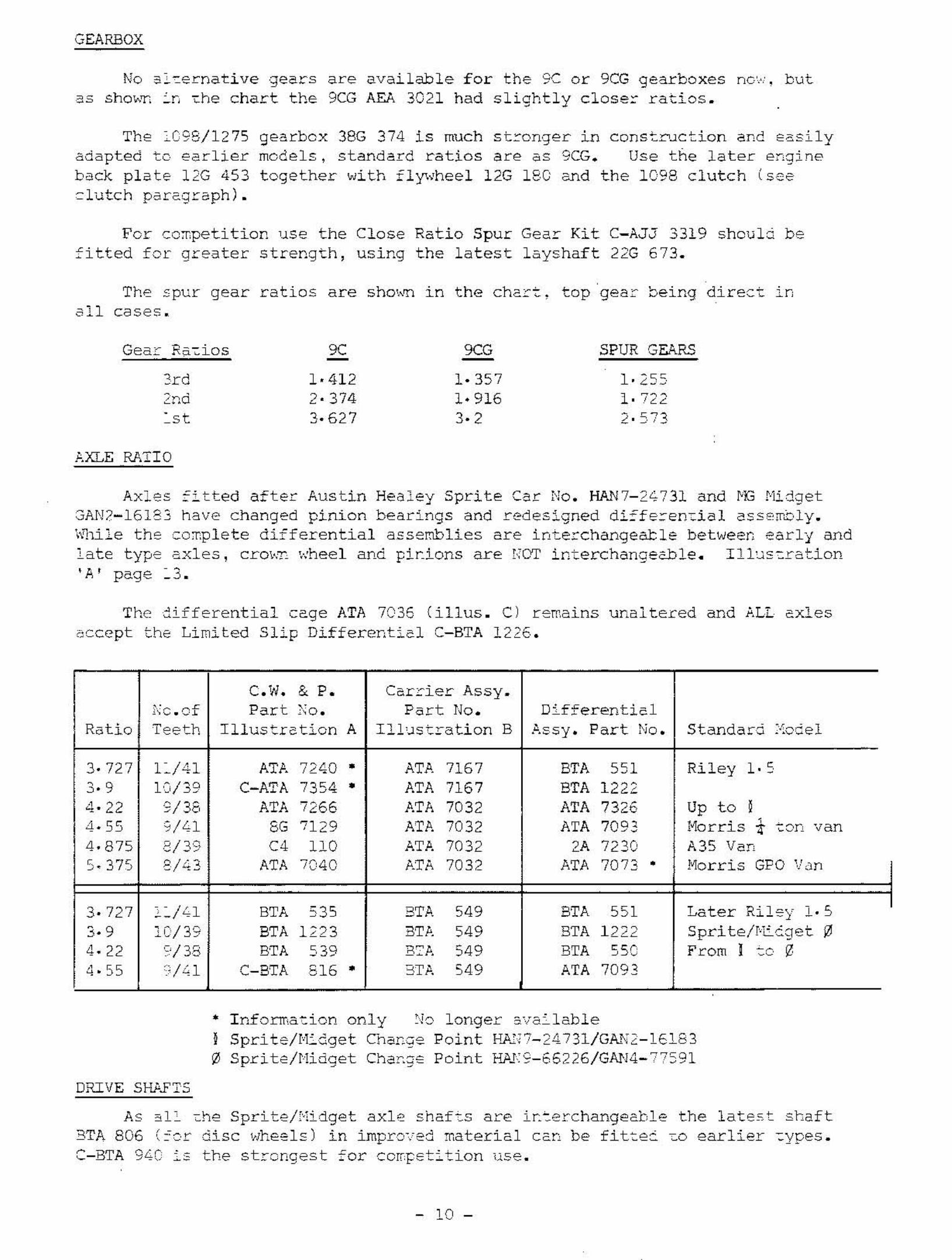
GEARBOX
No 3~~ernative gears are available for the 9C or 9CG gearboxes nc~:. butas sho~~ ~n ~he chart the 9CG AEA 3021 had slightly c1ose~ ratios.
The ~CS8/1275 gearbox 38G 374 is much stronger in const~~ction and easilyadapted to earlier models, standard ratios are as 9CG. Use the later engineback plate 12G 453 together with f1~vhee1 12G 180 and the 1098 clutch (seeclutch paragraph).
For co~petition use the Close Ratio Spur Gear Kit C-AJJ 3319 should befitted for greater strength, uSlng the latest layshaft 22G 673.
The spur gear ratios are sho~~ ln the chart, top gear being direct lDall cases.
Gear Rst Los 9C 9CG SPUR SURS
Src 1· 412 1·357 1·2552nd 2· 374 1·916 1· ~o,l "- "-
"s t 3·627 3· 2 ).r;,<.- -"-
;:.XLE RATIO
Axles fitted after Austin Healey Sprite Car No. HAN7-2473l and ~~ MidgetGAN?-161S3 have changed pinion bearings and redesigned di=fe~en~ia1 asse~~ly.
wlll1e the co~p1ete differential assemblies are interchangeable between early andlate type axles, c.rowr whee I and par-Loris are r:ar Lnter-chenoeebLe, Lj Lus t r at.jon'A' page ~3.
The differential cage ATA 7035 (iI1us. C) remolns unaltered and ALL axlesaccept the Limited Slip Differential C-BTA 1226.
C.W. & P. Carrier Assy.'.' L Part " Part No. Differentic 1.vcc or "0.
Ratio Teeth Il1ustrction A LjLus t r at.i.on B ~csy Part No. Standard :I,,'-; e 1..~. . .."'.....
3· 727 L/41 ATA ~~LO • AT!'. 7167 BTA 551 Riley 1· o.I "- •
3· 9 10::)/39 C-ATA 7354 • ATA 7167 BTA 12224- 22 9/36 ATA 7266 ATA 7032 ATA 7326 Up to I4·55 9/41 8G 7129 ATA 7032 ATA 7093 f-lo r-r-Ls
,
"' ~on van4·875 ,P/ <. c C4 no ATA 7032 2A 7230 A35 Van" ,,'S. 375 'I"~ ATA 7040 ATA 7032 ATA 7073 • Morris GPO veris· "<.:'>
3·727 "/Ll BTA 535 BTA 549 BTA 551 Later Ri Le'y 1. 5
3· 9 lC/39 BTA 1223 BTP. 549 BTA 1222 Spr-L te!!"': coer. 04_ 22 ':'/33 BTA o'q B:A 549 BTA "sr. From I ::0 0~' 5~ c "
4· 55 ,/Ll C-BTA 516 • 3TA 549 ATA 7093
• Information only ~o longer available} Sprite/Midget Cha~~e Point B~11~-24731/Gk~2-l6183
o Sprite/Midget Cha~ge Point By§S-65226/GAN4-77S91
DRIVE SHP.FTS
As 31~ ~he Sprite/Midget axle shafts are i~terchange2b1e the latest shaft3TA 806 (~or disc wheels) in impro~ed material can be fitte~ ~o earlier ~ypes.
C-BTA 94C is the strongest for ccn.pe td t i.on use.
- 10 -
DEEP SUMP
Wner~ oi l ser ge i s e xperienced caus~ng loss of oi l press~re momer.~ari l y ,
t he de~F sump s e t ki t shou l d be ins t a lled , C-AJ~ 3324A.
Thi s i s compl e t e with a l l necessary ~oints a~d an extended oi l pick uppipe .
OI L PC;·1P
I n a ll cases .che r e t he powe r unit is s t r i pped the oi l pu mp s ho ul d bec l os e ly examined and i f repl ~cEmen t is ne ce s s a ry use on l y 12G 79 3.
The Cooper ' 5 ' otl p~~p caP~ot be f~tted t o these models unl e s s t~~
s ha f t ~ s shor t e nec , which ~ocld weaken the shaf t a nd c aus e prema t ur ef ai l ur e .
COOLn;G SYSTEM
W~Ere sust ained maxi mun s pee ds a r e ~equired . ~he engi n e tne~ste = =anbe repl =c ed ' wi t h ~~ ou t l et blaL~ing sleeve k i t C- AJ J 4012 t o ens ure the ~2xi
mum f lo~ o f coo l a nt to the er.g~ne a t a l l t imes . Do not run ~ithout eitherthermost~t or sle eve .
ROAD WHEEL BALANCE
Th~ or i gina l degre e of ~heel ba l anc e may be affec t ed by tyre wear , cove rand t ub e r e pa i r s or t yr e r emova l and damage t o the r oad wheel . BalancE na yrequir~ re-checkin~ stat i c al ly and dyn3mica l ly eve=y few thou~and miles depender. ~ ~ntirely u;on t he cond i t ions unce~ which t he c a r ha s been opera~ ir.g .
usc t he tyres i r: the best condi t ion o r chos e wit...'L an even t r e ed wear on thef ront 0= =ar . Balanc ing a t yre havi ng f l a t s o r uneven we ar is not uS~2 1 1y
very s~~=essful .
,h en f i t t i ng ~~y non-star.~ard whee:s ~r tyres , it is essential to c heckt ha t ~~e t yre car~Q~ touch t~e br ake hose unde r ar.y condi tior:s . I t is ~0rth
mak in~ occasiona l checks th~ ~ no thing he 5 cha nged ~hich ma y pe~mit t he h~se t obecome ::hafcd .
~NHEELS
For compe t i t i on us e , s tre~gthened ~heels AR~ 645 5 shoul d be f itteci , whi chm~y be i den t i f ied by lack of v en t i l ati ng hol e s .
SHOCK :1.BSORBERS
Fc~ impr oved ~and ling s ~i f fer shock absorber s C- AHA 6451 R.H. a nd C-~HA
6452 L .~ . a re av~ilable f o r the f r ont of al l models . Adjustcble types 3reav ai lao:e f or the ~ear C-AP~ 7906 R. B. 3~C C- AHA 790 7 L. H. 2~ter chass~5
AN'J- 4 33 ;·.
'rhe-se requi r e a pla t e 5/ 32" ( 3. 9'.-') be t ween che shock a bs.c r be r- a nd bodv ,s ha pe 2~~ measureIe~ts a re deta i l ed wit~ ~he s hock ~bsorbers . The droplink: (6") s hou l d be replace d by t he s eender d 4~- " t ype of the e xisting C2r .
ROAD SP~INGS - R~2~
Jo. h e a vy dut y rea r road s. p r i.nq AHA ~, 4 6 8 ( 2whi c h ,~qui res lo~ger f i xi ng bol t s HBZ C624 ( 4als o aVa~lable t o ar.g l e t he spr i ngs up or downheight . Far t No . A_~ 64 56 ( 2 of f ) .
- 11 -
off: i s-f'at , .
t o 51,;i t
s t i l l avai labl e ,A taper pack i ng i st he requ i r ed r i de
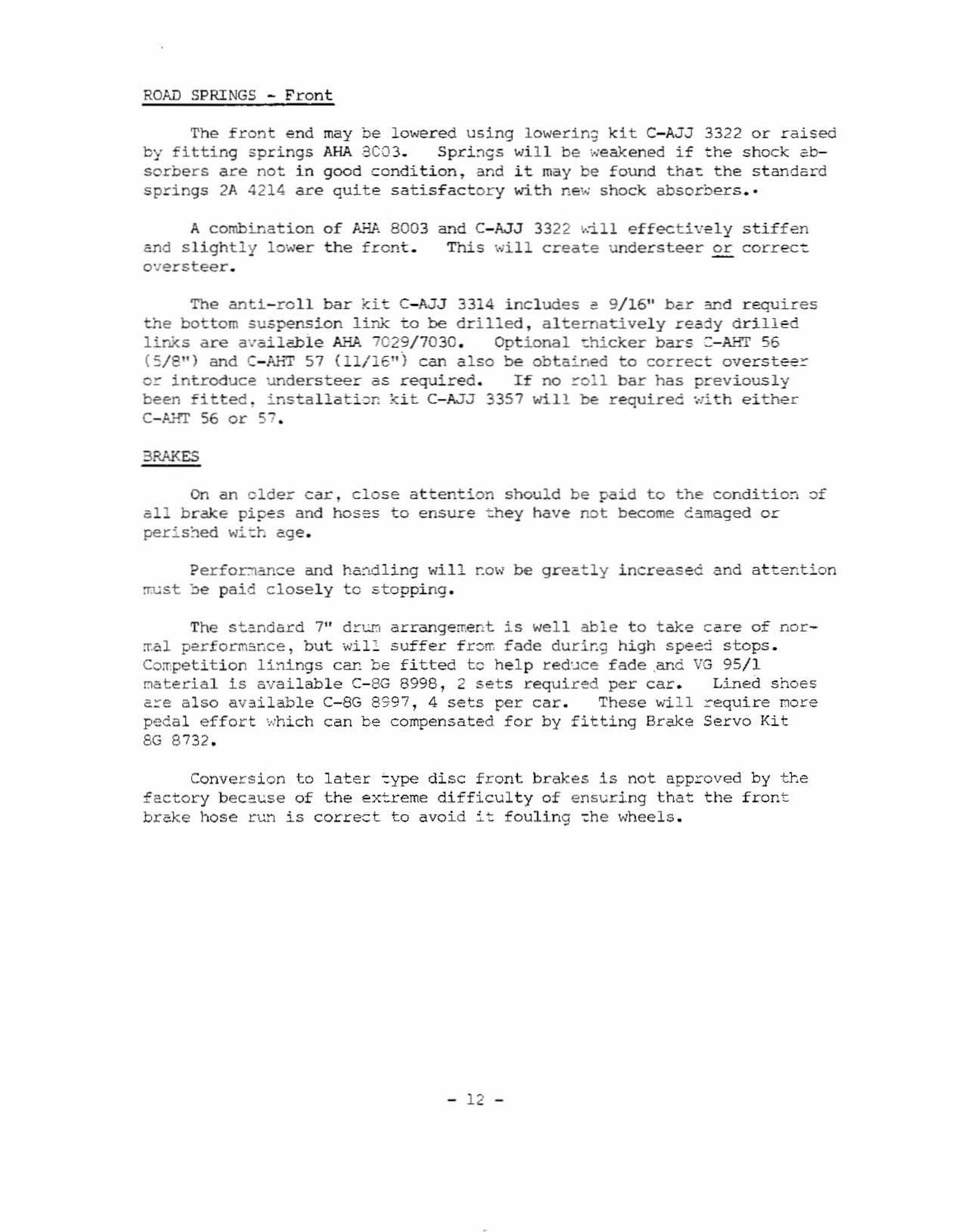
ROAD SPRINGS - Fr on t
The f r ont end may be lower ed using l owerin; k i t C- AJJ 3322 or r a i s edby fi tting spr i ngs AHA a C03. Spri~gs wi l l be ~eakened i f t he s hock absorbers are no t i n good condi t i on , and it may be f ound tha ~ the s tanda rds pr i ngs 2A 4214 are quit e satisfac t or y with ne~ s hock absor~ers • •
A combinat ion o f kYA 8003and s l i ght l y lowe r t he f r ont .over s t ee r •
and C- AJJ 3322 '~:i ll effec tivelyThis wi l l c reat e unders tee r o r
s t i ffencorrect
The ant.Le.rcLf bar ki t C-AJJ 3314 inc l udes e 9/ 16" bar 311d r equi r esthe bot tom suspensi on link t o be drilled , a l t ernativel y r eady d r il l edl inks a r e a~ai l~le AHA 702?/ 70 30 . Opt i onal ~hicker bars : -AHT 56( 5/ 8 1' ) and C-AHT 57 01/1 6" ) can a l so be obtained t o cor r ect ove r a t .ee ror i ntroduce under s t ee r a s r equi r ed . I f no r oll bar has previous lybeen fitted , Lns t.a Ll at. Lcr- kLt; C- AJJ 3357 will be r equir ed ·.·.'i th e i t he rC- Ai-IT 56 or 57.
3RAKES
On a n ol de r ca r , c l ose a ttention s hould be paid to the conditio~ ofa l l br ake pipes and hoses t o e ns ure ~hey have not become c~maged orperis~ed wi~h age .
Perfo~ance and hc~~ling will now be gr eatly i ncreas ed cnd a ttent i onrr.u s t he pai d c l os e l y t o 5t opping .
The s t andard 7" d'::-WO"I a r ranqerreot; is wel l able t o t ak e c are of nor~al perform5Dce , but wi l : s uffer f r offi fade during hi gh s peed s tops .Competiti on l i ni ngs can b e f i t t ed t c he l p red~ce fade .and VG 95/ 1~ate cial is ava i l ab l e C- 8G 8998 , 2 sets r equir ed per ca r . Lined s hoesa=e also aV3i l ab l e C-8G 899 7 , 4 s e t s pe r car . These wi ll ~equire Dorepeda l eff or t ~hich can be compens a t ed f or by f it t ing Br ake Ser vo Ki t8G 8 732.
Conver s ion t o lat e r ~ype dis c f r ont br akes 1s not approved by thef ac t ory beca~se of t he ex~reme diff i cu l t y of ensur i ng t hat the f rontbr ak e hose r un is correc t t o avoi d i~ f oul ing ~he whee ls .
- 12 -
. ",.
• 'So. ' 0
• ">: .'.••..-" .,.• """.'!HD
• I < •0_ ~ 0 0
.~I '. , ~,
":j , . '
"' i - -OJ " 00,0
', 35 •
'--~ , ~ •l,. '- •
,ISb•
Fig. -4
A secno» through tne flywheel
showing the area where lightening
is puminlble lOgelher with th e
machining dImensions
REMOVE BYGRINDING
REMOVE BY~--GRINDING
J<
Inlet port tem plate.
_ _ ~I!itt-I , l(·..·
Seetton through t he inlet port.
F i ~ . 1.
Fig. 2.
INLET PORT
-r
•
I
,
Fig. 3. Sect ion thro ugh the exhaust port.
I
B1 3


![[LOTNICTWO]Aerodata International Nr 005 - Hawker Hurricane Mk.I](https://img.dokumen.tips/doc/110x75/55cf9aa8550346d033a2c4c6/lotnictwoaerodata-international-nr-005-hawker-hurricane-mki.jpg)