Embed Size (px)
Citation preview
This Microgeneration Product Certification Standard is the property of Department of Energy and Climate Change (DECC), 3 Whitehall Place, London,SW1A 2HH.
© DECC 2013
Microgeneration Certification Scheme: MCS 007
Product Certification Scheme Requirements: Heat Pumps
Issue 3.0
Issue: 3.0 PRODUCT CERTIFICATION SCHEME REQUIREMENTS: HEAT PUMPS
MCS: 007
Date: 21/11/2014 Page 2 of 41
This Standard has been approved by the Steering Group of the Microgeneration Certification Scheme.
This document has been prepared by the MCS Working Group 6 ‘Heat Pumps’.
REVISION OF MICROGENERATION PRODUCT CERTIFICATION STANDARDS
Microgeneration Product Certification Standards will be revised by issue of revised editions or amendments. Details will be posted on the website at www.microgenerationcertification.org
Technical or other changes which affect the requirements for the approval or certification of the product or service will result in a new issue. Minor or administrative changes (e.g. corrections of spelling and typographical errors, changes to address and copyright details, the addition of notes for clarification etc.) may be made as amendments.
The issue number will be given in decimal format with the integer part giving the issue number and the fractional part giving the number of amendments (e.g. Issue 3.2 indicates that the document is at Issue 3 with 2 amendments).
Users of this Standard should ensure that they possess the latest issue and all amendments.
Issue: 3.0 PRODUCT CERTIFICATION SCHEME REQUIREMENTS: HEAT PUMPS
MCS: 007
Date: 21/11/2014 Page 3 of 41
TABLE OF CONTENTS
FOREWORD ................................................................................................................... 4
1. INTRODUCTION ............................................................................................... 5
2. SCOPE .............................................................................................................. 5
3. APPLICATIONS TO JOIN THE SCHEME ......................................................... 6
4. MANAGEMENT SYSTEMS CERTIFICATION ................................................... 6
5. CERTIFICATION AND APPROVAL ................................................................... 6
6. TECHNICAL DOCUMENTATION ...................................................................... 8
7. PERFORMANCE AND TESTING CRITERIA .................................................... 9
8. MAINTENANCE OF CERTIFICATION AND LISTING ..................................... 16
9. CERTIFICATION MARK AND LABELLING ..................................................... 17
Issue: 3.0 PRODUCT CERTIFICATION SCHEME REQUIREMENTS: HEAT PUMPS
MCS: 007
Date: 21/11/2014 Page 4 of 41
FOREWORD
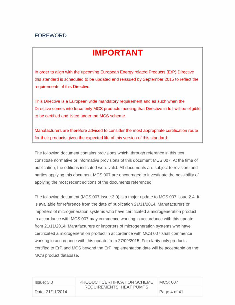
IMPORTANT
In order to align with the upcoming European Energy related Products (ErP) Directive
this standard is scheduled to be updated and reissued by September 2015 to reflect the
requirements of this Directive.
This Directive is a European wide mandatory requirement and as such when the
Directive comes into force only MCS products meeting that Directive in full will be eligible
to be certified and listed under the MCS scheme.
Manufacturers are therefore advised to consider the most appropriate certification route
for their products given the expected life of this version of this standard.
The following document contains provisions which, through reference in this text,
constitute normative or informative provisions of this document MCS 007. At the time of
publication, the editions indicated were valid. All documents are subject to revision, and
parties applying this document MCS 007 are encouraged to investigate the possibility of
applying the most recent editions of the documents referenced.
The following document (MCS 007 Issue 3.0) is a major update to MCS 007 issue 2.4. It
is available for reference from the date of publication 21/11/2014. Manufacturers or
importers of microgeneration systems who have certificated a microgeneration product
in accordance with MCS 007 may commence working in accordance with this update
from 21/11/2014. Manufacturers or importers of microgeneration systems who have
certificated a microgeneration product in accordance with MCS 007 shall commence
working in accordance with this update from 27/09/2015. For clarity only products
certified to ErP and MCS beyond the ErP implementation date will be acceptable on the
MCS product database.
Issue: 3.0 PRODUCT CERTIFICATION SCHEME REQUIREMENTS: HEAT PUMPS
MCS: 007
Date: 21/11/2014 Page 5 of 41
1. INTRODUCTION
This Scheme document identifies the evaluation and assessment requirements and
practices for the purposes of certification and listing of heat pumps. Certification and
listing of products is based on evidence acceptable to the Certification Body:-
that the product meets the Standard; and,
that the manufacturer has staff, processes and systems in place to ensure that
the product delivered meets the Standard.
And on:
periodic audits of the manufacturer including testing as appropriate; and,
compliance with the contract with the Certification Body for listing and approval
including agreement to rectify faults as appropriate.
2. SCOPE
This Scheme provides ongoing independent, third party assessment and approval of
companies who wish to demonstrate that their heat pump meets and continues to meet
the requirements of:
The appropriate Standard:
o EN 14511:2011 Parts 1 – 4 Air conditioners, liquid chilling packages and
heat pumps with electrically driven compressors for space heating and
cooling;
o EN 12309:2000 Parts 1 - 2 Gas-fired absorption and adsorption heat
pump appliances with a net heat input not exceeding 70 kW; or
o EN 16147:2011 “Heat pumps with electrically driven compressors.
Testing and requirements for marking of domestic hot water units.
The performance and testing criteria detailed in Section 7
The scope of this MCS product certification scheme document is limited to single heat
pumps up to a 45 kWth output, under the type test conditions specified in this Standard.
Issue: 3.0 PRODUCT CERTIFICATION SCHEME REQUIREMENTS: HEAT PUMPS
MCS: 007
Date: 21/11/2014 Page 6 of 41
Products used for the extraction of heat from loft spaces are excluded from this
Standard.
Heat pumps with electrically driven compressors designed to provide space heating and
domestic hot water shall be tested using the standard EN 14511.
In the case of electrically driven heat pumps which use CO2 as a refrigerant, the test
conditions stated in this standard shall apply.
Heat pumps with electrically driven compressors designed to provide domestic hot water
only shall be tested using the standard EN 16147 and Annex A of MCS 007.
Solar assisted heat pumps designed to provide domestic hot water only shall be tested
using the standard EN 16147, Annex A and Annex B of MCS 007.
3. APPLICATIONS TO JOIN THE SCHEME
Applications should be made to an accredited certification body operating this Scheme,
who will provide the appropriate application form and details of the applicable fees.
4. MANAGEMENT SYSTEMS CERTIFICATION
Manufacturers shall operate a certified documented manufacturing quality control
system, in accordance with the requirements of MCS 010 Generic Factory Production
Control Requirements.
5. CERTIFICATION AND APPROVAL
Certification and approval is based on the following:
a) Evidence of compliance with:
o BS EN14511:2011 Parts 1 – 4 of ‘Air conditioners, liquid chilling packages
and heat pumps with electrically driven compressors for space heating
and cooling’;
Issue: 3.0 PRODUCT CERTIFICATION SCHEME REQUIREMENTS: HEAT PUMPS
MCS: 007
Date: 21/11/2014 Page 7 of 41
o BS EN 12309:2000 Parts 1 - 2 ‘Gas-fired absorption and adsorption air-
conditioning and/or heat pump appliances with a net heat input not
exceeding 70 kW ‘; or
o EN 16147:2011 “Heat pumps with electrically driven compressors.
Testing and requirements for marking of domestic hot water units.”
Evidence of compliance is generally accepted as independent third party testing
by a UKAS (or equivalent) accredited test laboratory and based on the
performance and testing criteria outlined at Section 7. However, other evidence
of compliance may be considered at the discretion of the Certification Body (see
document MCS 011 Testing Acceptance Criteria);
b) Verification of the establishment and maintenance of the manufacturing
company’s quality management system in accordance with the Factory
Production Control requirements (FPC); and,
c) Review of the technical documentation relating to the material or product.
Applications for a range of common products (product families) will be dealt with on a case
by case basis. For example, where one or more characteristics are the same for products
with similar design, construction and functionality then the results of tests for these
characteristics on one product may be applied to other similar products.
A certificate is awarded following demonstration of satisfactory compliance with the
appropriate standard and this Scheme document, taking into account any limitations
imposed by the Standard and other appropriate guidelines, and satisfactory
verification/assessment of the manufacturer’s Factory Production Control and technical
documentation.
Certificates contain the name and address of the manufacturer, model and reference
number of the heat pump, a unique certificate reference number, the issue number, and
date.
Certificates are valid from the date of issue, and are maintained and held in force subject
to satisfactory completion of the requirements for maintenance of certification (see item
8), but remain the property of the issuing Certification Body.
Issue: 3.0 PRODUCT CERTIFICATION SCHEME REQUIREMENTS: HEAT PUMPS
MCS: 007
Date: 21/11/2014 Page 8 of 41
Details of the manufacturer and the certificated product(s) are listed at
www.microgenerationcertification.org
6. TECHNICAL DOCUMENTATION
Technical documentation for the product must be submitted for review. This
documentation shall be presented in English, and shall be such that it can be assured
that the products submitted for test are equivalent to those that are to be manufactured
for normal production. The documentation must consist of the following as a minimum;
a) Details of intended use, application and classifications (if any) required;
b) Manufacturing drawings and/or specifications including tolerances, issue and
revision numbers;
c) The revision number of the product;
d) Raw material and components specifications;
e) Details of the quality plan applied during manufacture to ensure ongoing
compliance;
f) Where historical test data is requested to be considered for the application, full
test report and details of any existing approvals (Note: each application will be
dealt with on a case by case basis and further information about the acceptance
of previous testing is available on request);
g) Weather compensation settings; and
h) Installation, use and maintenance instructions.
Issue: 3.0 PRODUCT CERTIFICATION SCHEME REQUIREMENTS: HEAT PUMPS
MCS: 007
Date: 21/11/2014 Page 9 of 41
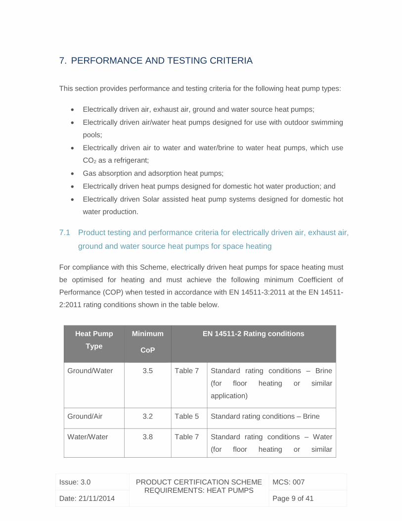
7. PERFORMANCE AND TESTING CRITERIA
This section provides performance and testing criteria for the following heat pump types:
Electrically driven air, exhaust air, ground and water source heat pumps;
Electrically driven air/water heat pumps designed for use with outdoor swimming
pools;
Electrically driven air to water and water/brine to water heat pumps, which use
CO2 as a refrigerant;
Gas absorption and adsorption heat pumps;
Electrically driven heat pumps designed for domestic hot water production; and
Electrically driven Solar assisted heat pump systems designed for domestic hot
water production.
7.1 Product testing and performance criteria for electrically driven air, exhaust air,
ground and water source heat pumps for space heating
For compliance with this Scheme, electrically driven heat pumps for space heating must
be optimised for heating and must achieve the following minimum Coefficient of
Performance (COP) when tested in accordance with EN 14511-3:2011 at the EN 14511-
2:2011 rating conditions shown in the table below.
Heat Pump
Type
Minimum
CoP
EN 14511-2 Rating conditions
Ground/Water 3.5 Table 7 Standard rating conditions – Brine
(for floor heating or similar
application)
Ground/Air 3.2 Table 5 Standard rating conditions – Brine
Water/Water 3.8 Table 7 Standard rating conditions – Water
(for floor heating or similar
Issue: 3.0 PRODUCT CERTIFICATION SCHEME REQUIREMENTS: HEAT PUMPS
MCS: 007
Date: 21/11/2014 Page 10 of 41
application)
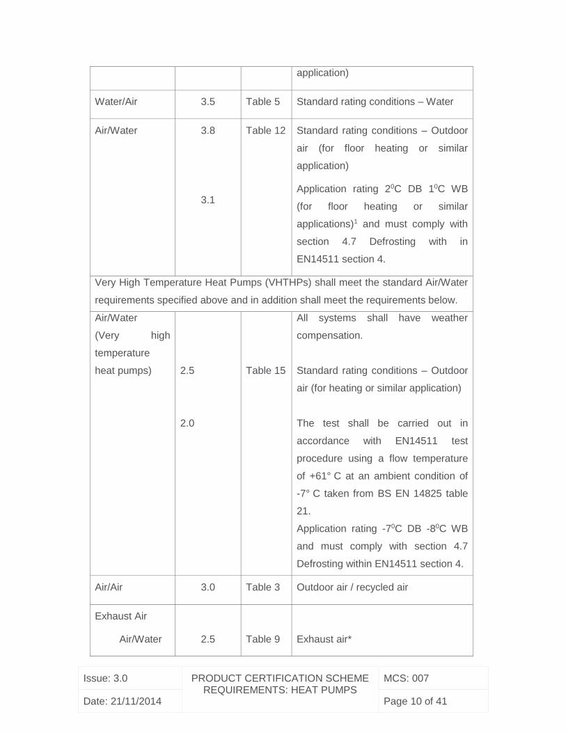
Water/Air 3.5 Table 5 Standard rating conditions – Water
Air/Water 3.8
3.1
Table 12 Standard rating conditions – Outdoor
air (for floor heating or similar
application)
Application rating 20C DB 10C WB
(for floor heating or similar
applications)1 and must comply with
section 4.7 Defrosting with in
EN14511 section 4.
Very High Temperature Heat Pumps (VHTHPs) shall meet the standard Air/Water
requirements specified above and in addition shall meet the requirements below.
Air/Water
(Very high
temperature
heat pumps)
2.5
2.0
Table 15
All systems shall have weather
compensation.
Standard rating conditions – Outdoor
air (for heating or similar application)
The test shall be carried out in
accordance with EN14511 test
procedure using a flow temperature
of +61° C at an ambient condition of
-7° C taken from BS EN 14825 table
21.
Application rating -70C DB -80C WB
and must comply with section 4.7
Defrosting within EN14511 section 4.
Air/Air 3.0 Table 3 Outdoor air / recycled air
Exhaust Air
Air/Water
2.5
Table 9
Exhaust air*
Issue: 3.0 PRODUCT CERTIFICATION SCHEME REQUIREMENTS: HEAT PUMPS
MCS: 007
Date: 21/11/2014 Page 11 of 41
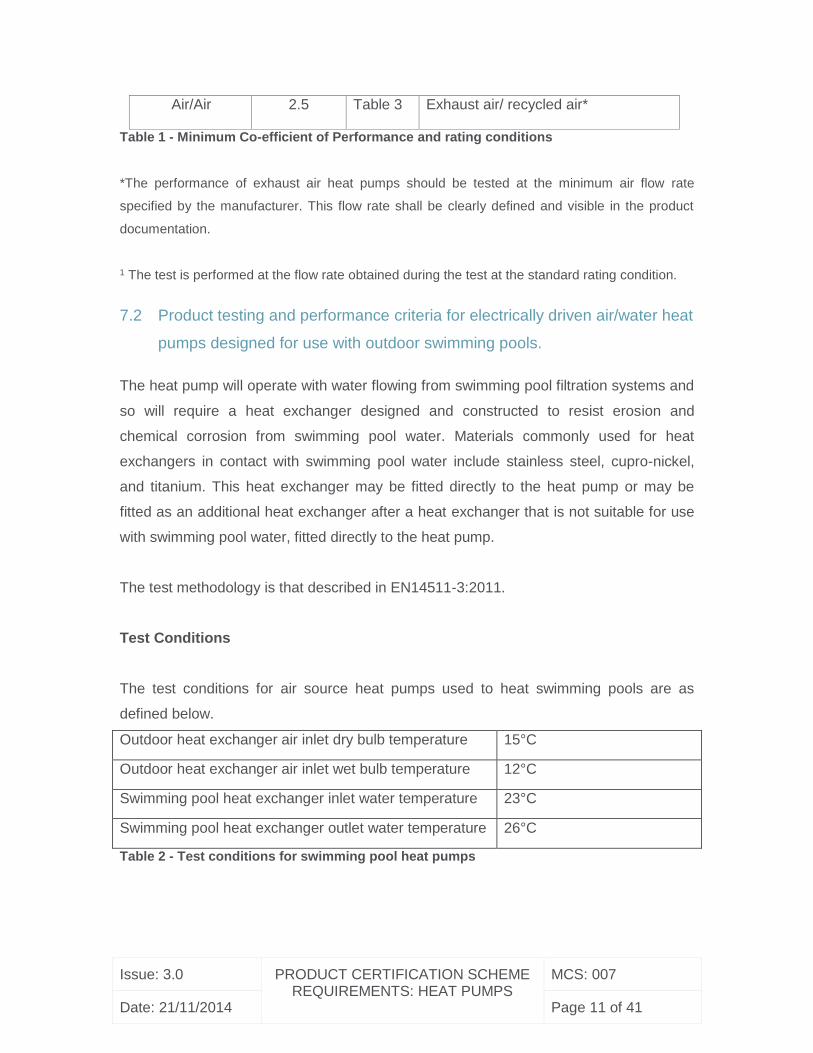
Air/Air 2.5 Table 3 Exhaust air/ recycled air*
Table 1 - Minimum Co-efficient of Performance and rating conditions
*The performance of exhaust air heat pumps should be tested at the minimum air flow rate
specified by the manufacturer. This flow rate shall be clearly defined and visible in the product
documentation.
1 The test is performed at the flow rate obtained during the test at the standard rating condition.
7.2 Product testing and performance criteria for electrically driven air/water heat
pumps designed for use with outdoor swimming pools.
The heat pump will operate with water flowing from swimming pool filtration systems and
so will require a heat exchanger designed and constructed to resist erosion and
chemical corrosion from swimming pool water. Materials commonly used for heat
exchangers in contact with swimming pool water include stainless steel, cupro-nickel,
and titanium. This heat exchanger may be fitted directly to the heat pump or may be
fitted as an additional heat exchanger after a heat exchanger that is not suitable for use
with swimming pool water, fitted directly to the heat pump.
The test methodology is that described in EN14511-3:2011.
Test Conditions
The test conditions for air source heat pumps used to heat swimming pools are as
defined below.
Outdoor heat exchanger air inlet dry bulb temperature 15°C
Outdoor heat exchanger air inlet wet bulb temperature 12°C
Swimming pool heat exchanger inlet water temperature 23°C
Swimming pool heat exchanger outlet water temperature 26°C
Table 2 - Test conditions for swimming pool heat pumps
Issue: 3.0 PRODUCT CERTIFICATION SCHEME REQUIREMENTS: HEAT PUMPS
MCS: 007
Date: 21/11/2014 Page 12 of 41
Measurement of the outlet water temperature should be performed as follows:
a. For heat pumps fitted with a heat exchanger suitable for use with swimming pool
water, the heat exchanger water outlet temperature should be measured directly.
b. For heat pumps that require an additional heat exchanger after the heat pump heat
exchanger, the outlet water temperature to the swimming pool should be measured at
the outlet of the additional heat exchanger.
Performance Requirement
When tested under the above conditions air source heat pumps used for heating
swimming pools must achieve a minimum COP of 3.6.
7.3 Product testing and performance criteria for electrically driven air to water and
water/brine to water heat pumps, which use CO2 as a refrigerant.
This document only applies to units using transcritical cycles, and self-sealed units.
Test Conditions and performance requirements – Water/brine to water heat pumps
Outdoor heat exchanger Indoor heat exchanger
Source
Inlet
temperature
(°C)
Outlet
temperature
(°C)
Inlet
temperature
(°C)
Outlet
temperature
(°C)
Minimum COP
Under floor
heating
Water 10 7 25 35 3.8
Brine 0 -3 25 35 3.6
Low
temperature
hot water
Water 10 7 30 50 3.5
Brine 0 -3 30 50 3.2
Domestic hot
water
Water 10 7 15 65 3.8
Brine 0 -3 15 65 3.6
Table 3 - Test conditions for water / brine heat pumps using CO2 as a refrigerant.
Issue: 3.0 PRODUCT CERTIFICATION SCHEME REQUIREMENTS: HEAT PUMPS
MCS: 007
Date: 21/11/2014 Page 13 of 41
Test Conditions and performance requirements – Air to water heat pumps
Outdoor heat exchanger Indoor heat exchanger
Air on dry
bulb
temperature
(°C)
Air on wet
bulb
temperature
(°C)
Inlet
temperature
(°C)
Outlet
temperature
(°C)
Minimum COP
Under floor
heating 7 6 25 35 3.5
Low
temperature
hot water
7 6 30 50 3.2
Domestic hot
water 7 6 15 65 3.2
Table 4 - Test conditions for air to water heat pumps using CO2 as a refrigerant.
The test methodology is that described in EN14511-3:2011
7.4 Product testing and performance criteria for gas absorption and adsorption heat
pumps
For compliance with this scheme, gas absorption or adsorption heat pumps must
achieve the following minimum Gas Utilisation Efficiency (GUEmcs) when tested in
accordance with EN 12309:2000 rating conditions shown in Table 5 using the Gross
Calorific Value for gas input:
Issue: 3.0 PRODUCT CERTIFICATION SCHEME REQUIREMENTS: HEAT PUMPS
MCS: 007
Date: 21/11/2014 Page 14 of 41
Heat Pump Type Minimum GUEmcs
Ground/Water 1.15
Water/Water 1.15
Air/Water 1.15
Table 5 - Minimum Gas Utilisation Efficiency (GUEmcs)
The calculation of GUEmcs should be performed as follows:
1. Calculate the electrical consumption using the default values of 3% for air source
heat pumps and 1.5% for ground source heat pumps (% of thermal output).
Example: a 40kWth air source appliance with a gross thermal input of 29 kWth, electrical
consumption will be estimated in 1.2 kWel)
2. Translate this value into primary energy with a co-efficient of 2.5 for energy
efficiency. Example : 1.2 kWel multiplied by 2.5 results in 3 kW of primary energy
input)
3. Calculate the total energy input by adding the gas input to the electrical input in
primary energy
Example: Total energy input will be 29 (thermal input) + 3 (primary energy input) = 32
kW)
4. Divide the output (from BS EN 12309) by the total input to obtain the Gas Utilisation
Efficiency. This figure shall then be compared to the thresholds outlined in Table 5.
Example: 40 kWth (output) / 32 kWth (total input) = 1.25 GUEmcs.)
Note: The above calculation uses gross calorific values (gcv) for gas input and then adds
the primary energy of any parasitical electrical load. EN 12309:2000 does not currently
require a calculation for GUEgcv nor parasitic load, however these may be included in
future versions of the standard. Therefore care is required when using data from
manufacturer’s literature published in accordance with EN 12309:2000.
Issue: 3.0 PRODUCT CERTIFICATION SCHEME REQUIREMENTS: HEAT PUMPS
MCS: 007
Date: 21/11/2014 Page 15 of 41
7.5 Product testing and performance criteria for electrically driven heat pumps
designed for domestic hot water production
The testing and performance requirements for electrically driven heat pumps designed
for domestic hot water production can be found at ‘Annex A - Product testing and criteria
for electrically driven heat pumps designed for domestic hot water production.’
7.6 Product testing and performance criteria for electrically driven solar assisted heat
pumps designed for domestic hot water production
The testing and performance requirements for solar assisted heat pumps designed for
domestic hot water production can be found at ‘Annex A - Product testing and criteria for
electrically driven heat pumps designed for domestic hot water production and Annex B
– Solar assisted heat pump solar test specification’
The manufacturer’s installation instruction document shall state clearly and explicitly the
maximum size of Domestic hot water storage cylinder to which the heat pump product
may be fitted. The maximum size of the cylinder specified in the manufacturer’s
installation manual shall comply with the requirements of the EN 16147:2011 or Lot 2
Tapping Cycle test that would be used to demonstrate that the solar assisted heat pump
product meets the performance requirements set out in MCS 007 for products of this
type.
The manufacturer’s installation manual shall clearly specify the number of panel(s) to be
used in association with the product including the domestic hot water cylinder size and
this must be in accordance with the test carried out under EN16147:2011.
Note: For example, if the solar assisted heat pump product is tested with a 200 litre
cylinder (with a large tapping cycle pattern) to qualify under MCS then the solar assisted
heat pump product should be certified for retrofitting to cylinder sizes of 200 litres or
below.
Issue: 3.0 PRODUCT CERTIFICATION SCHEME REQUIREMENTS: HEAT PUMPS
MCS: 007
Date: 21/11/2014 Page 16 of 41
8. MAINTENANCE OF CERTIFICATION AND LISTING
Certificates and listing are maintained and held in force subject to satisfactory
completion of the following requirements for maintenance of certification:
8.1 Factory Audits
Certification is maintained through annual FPC quality system audits, which shall include
a detailed check that the product being manufactured is to the same specification as the
product tested.
8.2 Product Audits
Product audits will be conducted as follows:
8.2.1 Review of the product technical data files including materials;
8.2.2 Review of end of line tests in accordance with the manufacturer’s quality plan;
and,
8.2.3 Repeat testing of elements from the product standard as appropriate to confirm
that the product continues to meet the requirements for certification and listing.
8.3 Product Data
8.3.1 Manufacturers shall make available to Installers and the Certification Body the
completed heat pump Distribution Network Operator (DNO) connection forms with all
relevant product data.
Issue: 3.0 PRODUCT CERTIFICATION SCHEME REQUIREMENTS: HEAT PUMPS
MCS: 007
Date: 21/11/2014 Page 17 of 41
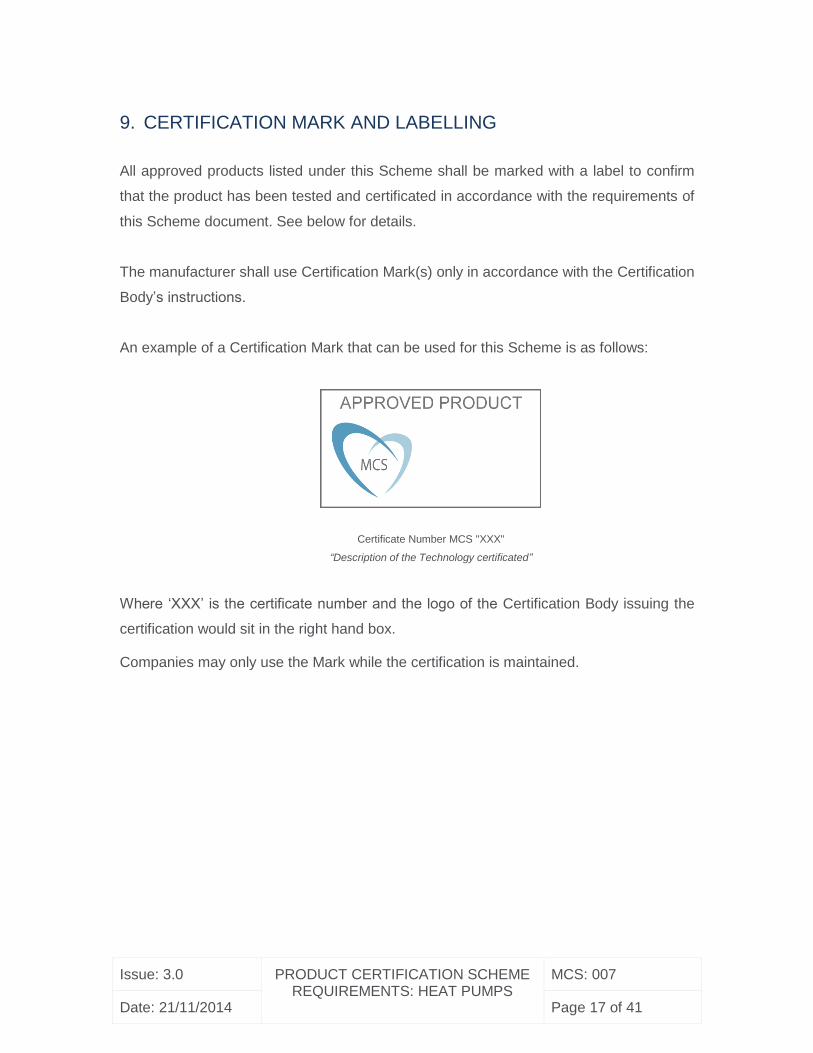
9. CERTIFICATION MARK AND LABELLING
All approved products listed under this Scheme shall be marked with a label to confirm
that the product has been tested and certificated in accordance with the requirements of
this Scheme document. See below for details.
The manufacturer shall use Certification Mark(s) only in accordance with the Certification
Body’s instructions.
An example of a Certification Mark that can be used for this Scheme is as follows:
Certificate Number MCS "XXX"
“Description of the Technology certificated”
Where ‘XXX’ is the certificate number and the logo of the Certification Body issuing the
certification would sit in the right hand box.
Companies may only use the Mark while the certification is maintained.
Issue: 3.0 PRODUCT CERTIFICATION SCHEME REQUIREMENTS: HEAT PUMPS
MCS: 007
Date: 21/11/2014 Page 18 of 41
REVISION OF MICROGENERATION CERTIFICATION SCHEME (MCS)
REQUIREMENTS
Microgeneration Certification Scheme (MCS) scheme requirements will be revised by
issue of revised editions or amendments. Details will be posted on our website at
www.microgenerationcertification.org
Technical or other changes which affect the requirements for the approval or certification
of the product or service will result in a new issue. Minor or administrative changes (e.g.
corrections of spelling and typographical errors, changes to address and copyright
details, the addition of notes for clarification etc.) may be made as amendments.
The issue number will be given in decimal format with the integer part giving the issue
number and the fractional part giving the number of amendments (e.g. Issue 3.2
indicates that the document is at Issue 3 with 2 amendments).
Users of this Standard should ensure that they possess the latest issue and all amendments.
Issue: 3.0 PRODUCT CERTIFICATION SCHEME REQUIREMENTS: HEAT PUMPS
MCS: 007
Date: 21/11/2014 Page 19 of 41
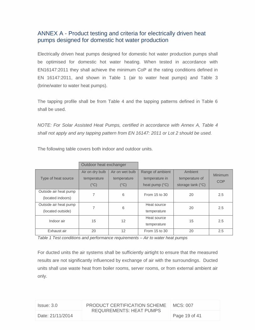
ANNEX A - Product testing and criteria for electrically driven heat pumps designed for domestic hot water production
Electrically driven heat pumps designed for domestic hot water production pumps shall
be optimised for domestic hot water heating. When tested in accordance with
EN16147:2011 they shall achieve the minimum CoP at the rating conditions defined in
EN 16147:2011, and shown in Table 1 (air to water heat pumps) and Table 3
(brine/water to water heat pumps).
The tapping profile shall be from Table 4 and the tapping patterns defined in Table 6
shall be used.
NOTE: For Solar Assisted Heat Pumps, certified in accordance with Annex A, Table 4
shall not apply and any tapping pattern from EN 16147: 2011 or Lot 2 should be used.
The following table covers both indoor and outdoor units.
Outdoor heat exchanger
Type of heat source
Air on dry bulb
temperature
(°C)
Air on wet bulb
temperature
(°C)
Range of ambient
temperature in
heat pump (°C)
Ambient
temperature of
storage tank (°C)
Minimum
COP
Outside air heat pump
(located indoors) 7 6 From 15 to 30 20 2.5
Outside air heat pump
(located outside) 7 6
Heat source
temperature 20 2.5
Indoor air 15 12 Heat source
temperature 15 2.5
Exhaust air 20 12 From 15 to 30 20 2.5
Table 1 Test conditions and performance requirements – Air to water heat pumps
For ducted units the air systems shall be sufficiently airtight to ensure that the measured
results are not significantly influenced by exchange of air with the surroundings. Ducted
units shall use waste heat from boiler rooms, server rooms, or from external ambient air
only.
Issue: 3.0 PRODUCT CERTIFICATION SCHEME REQUIREMENTS: HEAT PUMPS
MCS: 007
Date: 21/11/2014 Page 20 of 41
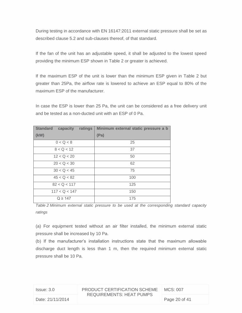
During testing in accordance with EN 16147:2011 external static pressure shall be set as
described clause 5.2 and sub-clauses thereof, of that standard.
If the fan of the unit has an adjustable speed, it shall be adjusted to the lowest speed
providing the minimum ESP shown in Table 2 or greater is achieved.
If the maximum ESP of the unit is lower than the minimum ESP given in Table 2 but
greater than 25Pa, the airflow rate is lowered to achieve an ESP equal to 80% of the
maximum ESP of the manufacturer.
In case the ESP is lower than 25 Pa, the unit can be considered as a free delivery unit
and be tested as a non-ducted unit with an ESP of 0 Pa.
Standard capacity ratings
(kW)
Minimum external static pressure a b
(Pa)
0 < Q < 8 25
8 < Q < 12 37
12 < Q < 20 50
20 < Q < 30 62
30 < Q < 45 75
45 < Q < 82 100
82 < Q < 117 125
117 < Q < 147 150
Q ≥ 147 175
Table 2 Minimum external static pressure to be used at the corresponding standard capacity
ratings
(a) For equipment tested without an air filter installed, the minimum external static
pressure shall be increased by 10 Pa.
(b) If the manufacturer’s installation instructions state that the maximum allowable
discharge duct length is less than 1 m, then the required minimum external static
pressure shall be 10 Pa.
Issue: 3.0 PRODUCT CERTIFICATION SCHEME REQUIREMENTS: HEAT PUMPS
MCS: 007
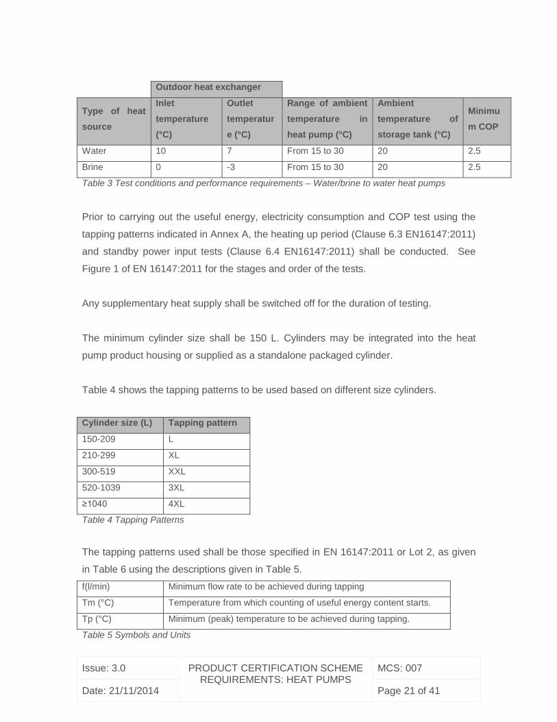
Date: 21/11/2014 Page 21 of 41
Outdoor heat exchanger
Type of heat
source
Inlet
temperature
(°C)
Outlet
temperatur
e (°C)
Range of ambient
temperature in
heat pump (°C)
Ambient
temperature of
storage tank (°C)
Minimu
m COP
Water 10 7 From 15 to 30 20 2.5
Brine 0 -3 From 15 to 30 20 2.5
Table 3 Test conditions and performance requirements – Water/brine to water heat pumps
Prior to carrying out the useful energy, electricity consumption and COP test using the
tapping patterns indicated in Annex A, the heating up period (Clause 6.3 EN16147:2011)
and standby power input tests (Clause 6.4 EN16147:2011) shall be conducted. See
Figure 1 of EN 16147:2011 for the stages and order of the tests.
Any supplementary heat supply shall be switched off for the duration of testing.
The minimum cylinder size shall be 150 L. Cylinders may be integrated into the heat
pump product housing or supplied as a standalone packaged cylinder.
Table 4 shows the tapping patterns to be used based on different size cylinders.
Cylinder size (L) Tapping pattern
150-209 L
210-299 XL
300-519 XXL
520-1039 3XL
≥1040 4XL
Table 4 Tapping Patterns
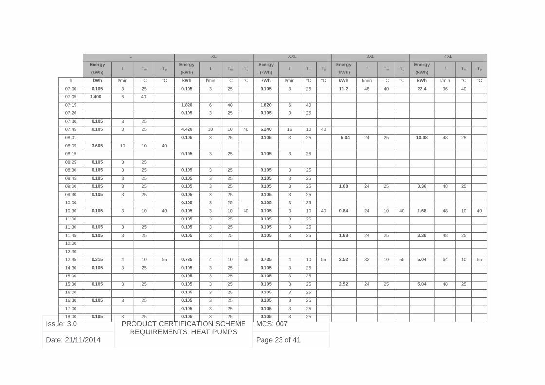
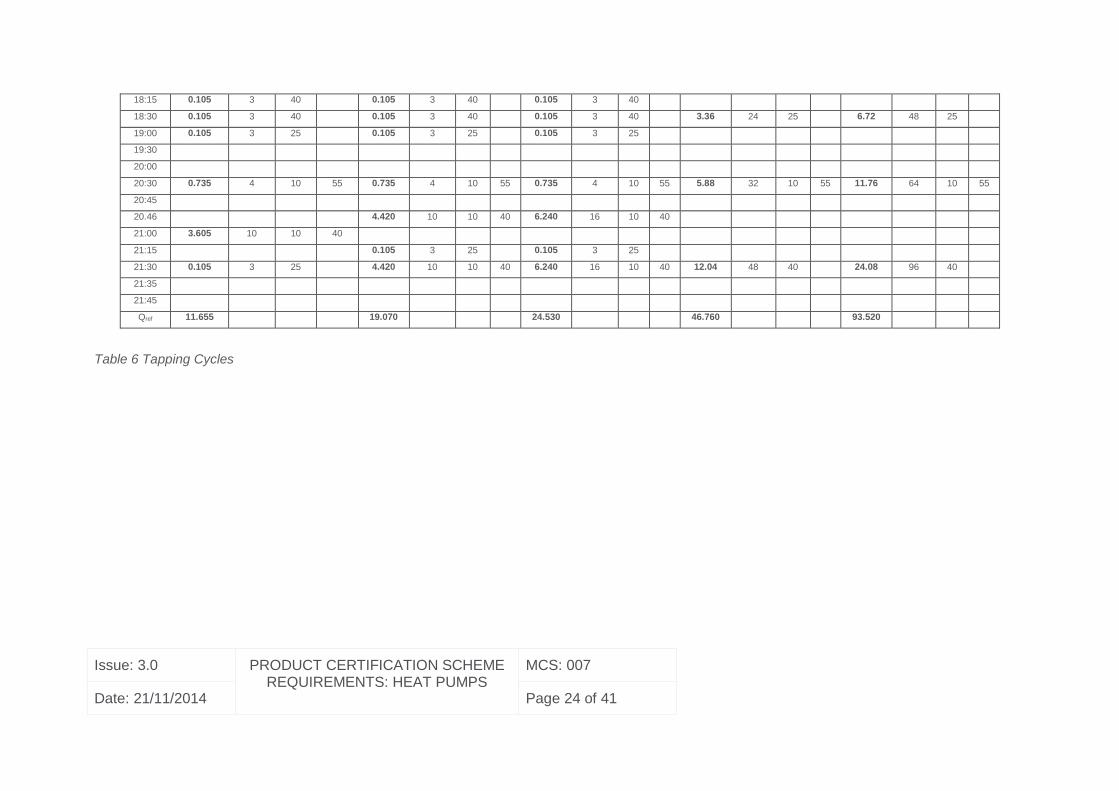
The tapping patterns used shall be those specified in EN 16147:2011 or Lot 2, as given
in Table 6 using the descriptions given in Table 5.
f(l/min) Minimum flow rate to be achieved during tapping
Tm (°C) Temperature from which counting of useful energy content starts.
Tp (°C) Minimum (peak) temperature to be achieved during tapping.
Table 5 Symbols and Units
Issue: 3.0 PRODUCT CERTIFICATION SCHEME REQUIREMENTS: HEAT PUMPS
MCS: 007
Date: 21/11/2014 Page 22 of 41
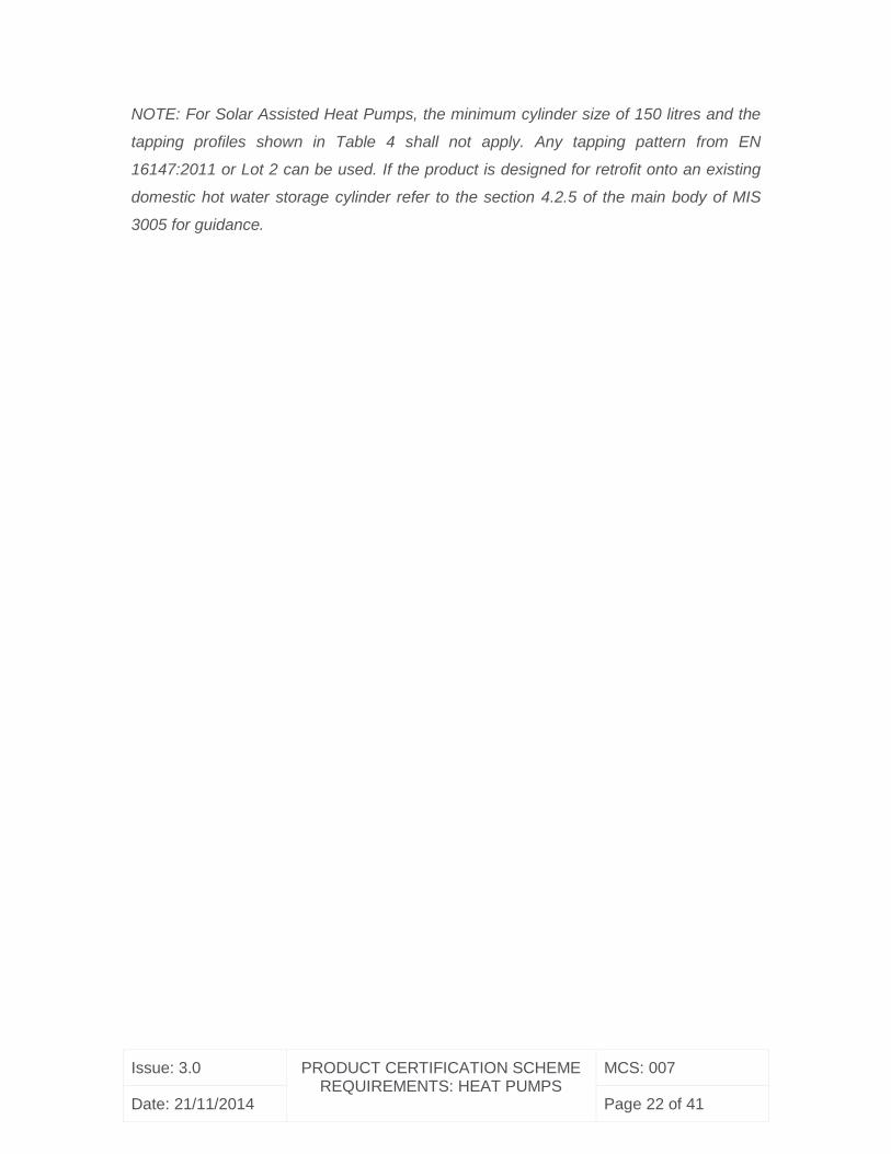
NOTE: For Solar Assisted Heat Pumps, the minimum cylinder size of 150 litres and the
tapping profiles shown in Table 4 shall not apply. Any tapping pattern from EN
16147:2011 or Lot 2 can be used. If the product is designed for retrofit onto an existing
domestic hot water storage cylinder refer to the section 4.2.5 of the main body of MIS
3005 for guidance.
Issue: 3.0 PRODUCT CERTIFICATION SCHEME REQUIREMENTS: HEAT PUMPS
MCS: 007
Date: 21/11/2014 Page 23 of 41
L XL XXL 3XL 4XL
Energy
(kWh)
f Tm Tp
Energy
(kWh)
f Tm Tp
Energy
(kWh)
f Tm Tp
Energy
(kWh)
f Tm Tp
Energy
(kWh)
f Tm Tp
h kWh l/min °C °C kWh l/min °C °C kWh l/min °C °C kWh l/min °C °C kWh l/min °C °C
07:00 0.105 3 25 0.105 3 25 0.105 3 25 11.2 48 40 22.4 96 40
07:05 1.400 6 40
07:15 1.820 6 40 1.820 6 40
07:26 0.105 3 25 0.105 3 25
07:30 0.105 3 25
07:45 0.105 3 25 4.420 10 10 40 6.240 16 10 40
08:01 0.105 3 25 0.105 3 25 5.04 24 25 10.08 48 25
08:05 3.605 10 10 40
08:15 0.105 3 25 0.105 3 25
08:25 0.105 3 25
08:30 0.105 3 25 0.105 3 25 0.105 3 25
08:45 0.105 3 25 0.105 3 25 0.105 3 25
09:00 0.105 3 25 0.105 3 25 0.105 3 25 1.68 24 25 3.36 48 25
09:30 0.105 3 25 0.105 3 25 0.105 3 25
10:00 0.105 3 25 0.105 3 25
10:30 0.105 3 10 40 0.105 3 10 40 0.105 3 10 40 0.84 24 10 40 1.68 48 10 40
11:00 0.105 3 25 0.105 3 25
11:30 0.105 3 25 0.105 3 25 0.105 3 25
11:45 0.105 3 25 0.105 3 25 0.105 3 25 1.68 24 25 3.36 48 25
12:00
12:30
12:45 0.315 4 10 55 0.735 4 10 55 0.735 4 10 55 2.52 32 10 55 5.04 64 10 55
14:30 0.105 3 25 0.105 3 25 0.105 3 25
15:00 0.105 3 25 0.105 3 25
15:30 0.105 3 25 0.105 3 25 0.105 3 25 2.52 24 25 5.04 48 25
16:00 0.105 3 25 0.105 3 25
16:30 0.105 3 25 0.105 3 25 0.105 3 25
17:00 0.105 3 25 0.105 3 25
18:00 0.105 3 25 0.105 3 25 0.105 3 25
Issue: 3.0 PRODUCT CERTIFICATION SCHEME REQUIREMENTS: HEAT PUMPS
MCS: 007
Date: 21/11/2014 Page 24 of 41
Table 6 Tapping Cycles
18:15 0.105 3 40 0.105 3 40 0.105 3 40
18:30 0.105 3 40 0.105 3 40 0.105 3 40 3.36 24 25 6.72 48 25
19:00 0.105 3 25 0.105 3 25 0.105 3 25
19:30
20:00
20:30 0.735 4 10 55 0.735 4 10 55 0.735 4 10 55 5.88 32 10 55 11.76 64 10 55
20:45
20.46 4.420 10 10 40 6.240 16 10 40
21:00 3.605 10 10 40
21:15 0.105 3 25 0.105 3 25
21:30 0.105 3 25 4.420 10 10 40 6.240 16 10 40 12.04 48 40 24.08 96 40
21:35
21:45
Qref 11.655 19.070 24.530 46.760 93.520
Issue: 3.0 PRODUCT CERTIFICATION SCHEME REQUIREMENTS: HEAT PUMPS
MCS: 007
Date: 21/11/2014 Page 25 of 41
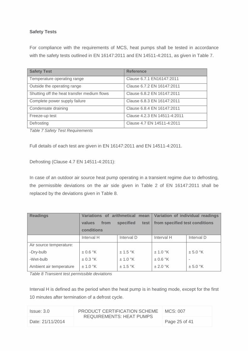
Safety Tests
For compliance with the requirements of MCS, heat pumps shall be tested in accordance
with the safety tests outlined in EN 16147:2011 and EN 14511-4:2011, as given in Table 7.
Safety Test Reference
Temperature operating range Clause 6.7.1 EN16147:2011
Outside the operating range Clause 6.7.2 EN 16147:2011
Shutting off the heat transfer medium flows Clause 6.8.2 EN 16147:2011
Complete power supply failure Clause 6.8.3 EN 16147:2011
Condensate draining Clause 6.8.4 EN 16147:2011
Freeze-up test Clause 4.2.3 EN 14511-4:2011
Defrosting Clause 4.7 EN 14511-4:2011
Table 7 Safety Test Requirements
Full details of each test are given in EN 16147:2011 and EN 14511-4:2011.
Defrosting (Clause 4.7 EN 14511-4:2011):
In case of an outdoor air source heat pump operating in a transient regime due to defrosting,
the permissible deviations on the air side given in Table 2 of EN 16147:2011 shall be
replaced by the deviations given in Table 8.
Readings Variations of arithmetical mean
values from specified test
conditions
Variation of individual readings
from specified test conditions
Interval H Interval D Interval H Interval D
Air source temperature:
-Dry-bulb
-Wet-bulb
Ambient air temperature
± 0.6 °K
± 0.3 °K
± 1.0 °K
± 1.5 °K
± 1.0 °K
± 1.5 °K
± 1.0 °K
± 0.6 °K
± 2.0 °K
± 5.0 °K
-
± 5.0 °K
Table 8 Transient test permissible deviations
Interval H is defined as the period when the heat pump is in heating mode, except for the first
10 minutes after termination of a defrost cycle.
Issue: 3.0 PRODUCT CERTIFICATION SCHEME REQUIREMENTS: HEAT PUMPS
MCS: 007
Date: 21/11/2014 Page 26 of 41
Interval D is defined as the period including a defrost cycle and the first 10 minutes after the
termination of a defrost cycle when the heat pump is back operating in the heating mode.
Table 8 is used in EN 14511 for heat pumps using outdoor air as the heat source.
Sound characteristic test
The purpose of the sound characteristic test is to determine the maximum sound power level
of the heat pump during a heating up period.
For compliance with this scheme, a sound characteristic test shall be performed using the
following methodology:
1. The sound power level of the heat pump shall be determined using a Class A
methodology as described in EN 12102.
2. The settings and test conditions shall be the same as the thermal performance tests
(see Table 5 EN 16147:2011). The water outlet temperature set point shall be set to
maximum.
3. The heating up period (Clause 6.3 of EN 16147:2011) shall be carried out and the
water outlet temperature shall be checked by regularly carrying out small draw-offs.
4. The first sound measurement (T0) shall be carried out immediately after a draw-off,
providing the water outlet temperature has reached 45°C ±2°C (See figure below).
5. A second draw-off followed by a sound measurement shall be carried out 10 minutes
after T0, and shall be repeated every 10 minutes thereafter.
6. The final sound measurement shall be carried out after 30 minutes have elapsed, or if
the water outlet temperature reaches 55°C ±2°C.
7. If less than four sound measurements are carried out then the test shall be repeated
until four sound measurements in total have been performed.
8. The four sound measurements shall be used to determine the sound power level of
the heat pump. The maximum determined sound power level shall be used to declare
the sound power level of the unit.
9. If there is a wide variation in the determined overall A-weighted sound power levels (>
2dB) then four more sound measurements shall be carried out. If there is still a wide
variation in the determined sound power levels, and it can be shown that the testing
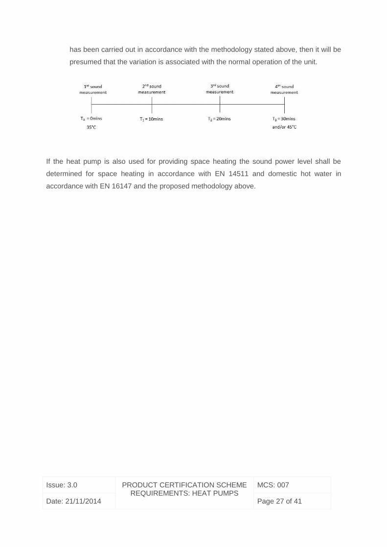
Issue: 3.0 PRODUCT CERTIFICATION SCHEME REQUIREMENTS: HEAT PUMPS
MCS: 007
Date: 21/11/2014 Page 27 of 41
has been carried out in accordance with the methodology stated above, then it will be
presumed that the variation is associated with the normal operation of the unit.
If the heat pump is also used for providing space heating the sound power level shall be
determined for space heating in accordance with EN 14511 and domestic hot water in
accordance with EN 16147 and the proposed methodology above.
Issue: 3.0 PRODUCT CERTIFICATION SCHEME REQUIREMENTS: HEAT PUMPS
MCS: 007
Date: 21/11/2014 Page 28 of 41
Annex B – Product testing and performance criteria for solar assisted heat
pumps designed for domestic hot water production
1. Scope
This annex specifies tests to be performed on solar assisted heat pump systems for
domestic hot water production, of durability (including mechanical strength), reliability and
safety of the external absorbers they incorporate. These requirements are in addition to the
requirements of EN16147. This annex also includes provision for the evaluation of conformity
to these additional requirements.
An EN12975 test report would meet the requirements of the tests 6, 7, 8, 9, 10 and 11. For
the avoidance of doubt, the thermal performance requirements of EN12975 are not included
within the requirements of this Annex.
2. Normative references
The following documents, in whole or in part, are normatively referenced in this document
and are indispensable for its application. For dated references, only the edition cited applies.
For undated references, the latest edition of the referenced document (including any
amendments) applies.
EN ISO 9488, Solar energy - Vocabulary (ISO 9488:1999)
EN ISO 9806:2013, Solar energy - Solar Thermal collectors - Test methods
EN 12975:2006, Thermal solar systems and components – Solar collectors
EN 16147:2011, Heat pumps with electrically driven compressors - Testing and requirements
for marking of domestic hot water units
3. Terms and definitions
For the purposes of this document, the symbols and units given in EN ISO 9488 apply.
Issue: 3.0 PRODUCT CERTIFICATION SCHEME REQUIREMENTS: HEAT PUMPS
MCS: 007
Date: 21/11/2014 Page 29 of 41
External absorber - A panel which performs the function of an evaporator in a
thermodynamic solar assisted heat pump system. This device is remote from the compressor
and is usually mounted externally.
4. Symbols and units
For the purposes of this document, the symbols and units given in EN ISO 9488 and EN
12975-2 apply.
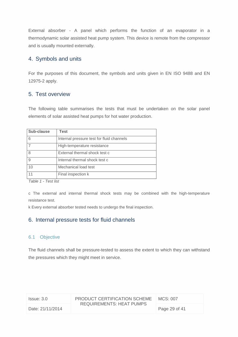
5. Test overview
The following table summarises the tests that must be undertaken on the solar panel
elements of solar assisted heat pumps for hot water production.
Sub-clause Test
6 Internal pressure test for fluid channels
7 High-temperature resistance
8 External thermal shock test c
9 Internal thermal shock test c
10 Mechanical load test
11 Final inspection k
Table 1 - Test list
c The external and internal thermal shock tests may be combined with the high-temperature
resistance test.
k Every external absorber tested needs to undergo the final inspection.
6. Internal pressure tests for fluid channels
6.1 Objective
The fluid channels shall be pressure-tested to assess the extent to which they can withstand
the pressures which they might meet in service.
Issue: 3.0 PRODUCT CERTIFICATION SCHEME REQUIREMENTS: HEAT PUMPS
MCS: 007
Date: 21/11/2014 Page 30 of 41
6.2 Apparatus and procedure
The apparatus consists of a hydraulic pressure source (electrical pump or hand pump), a
safety valve, an air-bleed valve and a pressure gauge with a standard uncertainty better than
5%. The air-bleed valve shall be used to empty the fluid channels of air before
pressurization. The fluid channels shall be filled with nitrogen and pressurized to the test
pressure for the test period. This pressure shall be maintained while the fluid channels are
inspected for swelling, distortion or ruptures.
6.3 Test conditions
Fluid channels shall be pressure-tested at ambient temperature within the range 5 °C to 40
°C, shielded from light. The test pressure shall be 1,5 times the maximum external absorber
operating pressure specified by the manufacturer. The test pressure shall be maintained (±5
%) for 15 min.
6.4 Results
The external absorber shall be inspected for leakage, swelling and distortion. Leakage can
be assumed if pressure loss ΔP > 5 % of the test pressure or 17 kPa, whichever is greater.
The results of this inspection shall be reported together with the values of pressure and
temperature used and the duration of the test.
7. High-temperature resistance test
7.1 Objective
This test is intended to assess rapidly whether an external absorber can withstand high
temperature and irradiance levels without failures such as significant deposits on the external
absorber cover from outgassing of external absorber material or any other effect that
possibly could lead to reduced performance, lifetime, safety or distorted visual appearance of
the external absorber.
7.2 Apparatus and procedure
The external absorber shall be tested outdoors, or in a solar irradiance simulator. The
characteristics of the solar irradiance simulator to be used for the high-temperature
Issue: 3.0 PRODUCT CERTIFICATION SCHEME REQUIREMENTS: HEAT PUMPS
MCS: 007
Date: 21/11/2014 Page 31 of 41
resistance test shall be those of the solar irradiance simulator used for efficiency testing of
fluid heating external absorbers.
The external absorbers shall be mounted outdoors or in a solar simulator. Liquid heating
external absorbers shall not be filled with fluid. All of the fluid pipes except for one shall be
sealed to prevent cooling by natural circulation of air.
A temperature sensor shall be attached to the absorber to monitor its temperature during the
test. The sensor shall be positioned in the hottest region of the external absorber. The
location shall be reported with the results. In case of liquid flat plate external absorbers the
hottest region can be assumed at two-thirds of the absorber height and half the absorber
width. It shall be fixed firmly in a position to ensure good thermal contact with the absorber.
The sensor shall be shielded from solar radiation.
The test shall be performed for a minimum of 1 h after steady-state conditions have been
established (steady-state conditions can be assumed for absorber temperatures changes of
less than ± 5 K for 30 minutes), and the external absorber shall be subsequently inspected
for signs of damage.
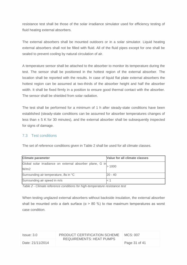
7.3 Test conditions
The set of reference conditions given in Table 2 shall be used for all climate classes.
Climate parameter Value for all climate classes
Global solar irradiance on external absorber plane, G in
W/m2 > 1000
Surrounding air temperature, ϑa in °C 20 - 40
Surrounding air speed in m/s < 1
Table 2 - Climate reference conditions for high-temperature resistance test
When testing unglazed external absorbers without backside insulation, the external absorber
shall be mounted onto a dark surface (α > 80 %) to rise maximum temperatures as worst
case condition.
Issue: 3.0 PRODUCT CERTIFICATION SCHEME REQUIREMENTS: HEAT PUMPS
MCS: 007
Date: 21/11/2014 Page 32 of 41
7.4 Results
The external absorber shall be inspected for degradation, shrinkage, outgassing and
distortion.
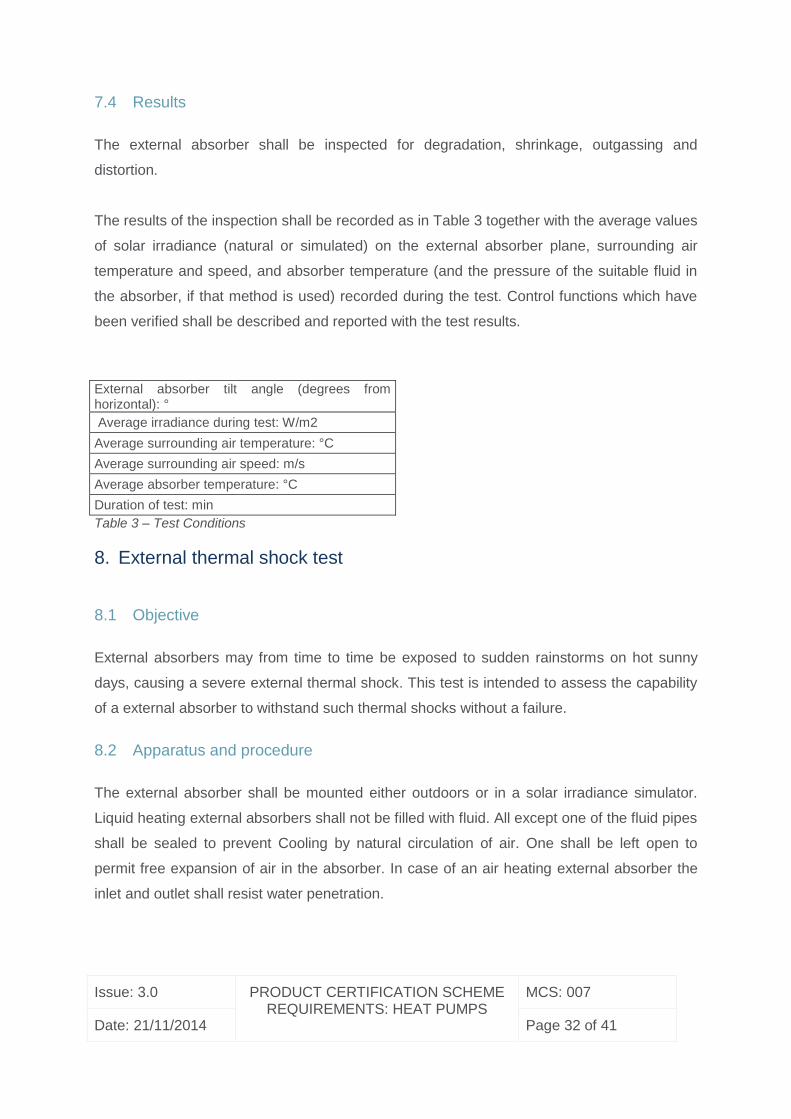
The results of the inspection shall be recorded as in Table 3 together with the average values
of solar irradiance (natural or simulated) on the external absorber plane, surrounding air
temperature and speed, and absorber temperature (and the pressure of the suitable fluid in
the absorber, if that method is used) recorded during the test. Control functions which have
been verified shall be described and reported with the test results.
External absorber tilt angle (degrees from horizontal): °
Average irradiance during test: W/m2
Average surrounding air temperature: °C
Average surrounding air speed: m/s
Average absorber temperature: °C
Duration of test: min
Table 3 – Test Conditions
8. External thermal shock test
8.1 Objective
External absorbers may from time to time be exposed to sudden rainstorms on hot sunny
days, causing a severe external thermal shock. This test is intended to assess the capability
of a external absorber to withstand such thermal shocks without a failure.
8.2 Apparatus and procedure
The external absorber shall be mounted either outdoors or in a solar irradiance simulator.
Liquid heating external absorbers shall not be filled with fluid. All except one of the fluid pipes
shall be sealed to prevent Cooling by natural circulation of air. One shall be left open to
permit free expansion of air in the absorber. In case of an air heating external absorber the
inlet and outlet shall resist water penetration.
Issue: 3.0 PRODUCT CERTIFICATION SCHEME REQUIREMENTS: HEAT PUMPS
MCS: 007
Date: 21/11/2014 Page 33 of 41
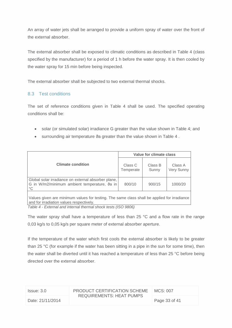
An array of water jets shall be arranged to provide a uniform spray of water over the front of
the external absorber.
The external absorber shall be exposed to climatic conditions as described in Table 4 (class
specified by the manufacturer) for a period of 1 h before the water spray. It is then cooled by
the water spray for 15 min before being inspected.
The external absorber shall be subjected to two external thermal shocks.
8.3 Test conditions
The set of reference conditions given in Table 4 shall be used. The specified operating
conditions shall be:
solar (or simulated solar) irradiance G greater than the value shown in Table 4; and
surrounding air temperature ϑa greater than the value shown in Table 4 .
Climate condition
Value for climate class
Class C Temperate
Class B Sunny
Class A Very Sunny
Global solar irradiance on external absorber plane, G in W/m2/minimum ambient temperature, ϑa in °C
800/10 900/15 1000/20
Values given are minimum values for testing. The same class shall be applied for irradiance and for irradiation values respectively.
Table 4 - External and internal thermal shock tests (ISO 9806)
The water spray shall have a temperature of less than 25 °C and a flow rate in the range
0,03 kg/s to 0,05 kg/s per square meter of external absorber aperture.
If the temperature of the water which first cools the external absorber is likely to be greater
than 25 °C (for example if the water has been sitting in a pipe in the sun for some time), then
the water shall be diverted until it has reached a temperature of less than 25 °C before being
directed over the external absorber.
Issue: 3.0 PRODUCT CERTIFICATION SCHEME REQUIREMENTS: HEAT PUMPS
MCS: 007
Date: 21/11/2014 Page 34 of 41
8.4 Results
The external absorber shall be inspected for any cracking, distortion, water penetration or
loss of vacuum. The results of the inspection shall be reported. The measured values of solar
irradiance, surrounding air temperature, fluid channel temperature (if measured), water
temperature and water flow rate shall also be reported.
9. Internal thermal shock test
9.1 Objective
External absorbers may from time to time be exposed to a sudden intake of cold heat
transfer fluid on hot sunny days, causing a severe internal thermal shock, for example, after
a period of shutdown, when the installation is brought back into operation while the external
absorber is at a elevated temperature. This test is intended to assess the capability of a
external absorber to withstand such thermal shocks without failure.
9.2 Apparatus and procedure
The external absorber shall be mounted either outdoors or in a solar irradiance simulator.
Liquid heating external absorbers shall not be filled with fluid. One of its fluid pipes shall be
connected via a shutoff valve to the heat transfer fluid source and the other shall be left open
initially to permit the free expansion of air in the absorber and also to permit the heat transfer
fluid to leave the absorber (and be collected). If the external absorber has more than two fluid
pipes, the remaining openings shall be sealed in a way that ensures the designed flow
pattern within the external absorber.
The external absorber shall be exposed to climatic conditions as described in Table 4 (class
specified by the manufacturer) for a period of 1 h before it is cooled by supplying it with heat
transfer fluid for at least 5 min.
The external absorber shall be subjected to two internal thermal shocks.
This test is not applicable to those parts of the external absorber which are factory sealed. It
is not applicable to those external absorbers in which heat transfer fluid is continuously
Issue: 3.0 PRODUCT CERTIFICATION SCHEME REQUIREMENTS: HEAT PUMPS
MCS: 007
Date: 21/11/2014 Page 35 of 41
flowing for protection purposes. In that case control(s) used to manage a no-flow condition
shall be validated to be functional in such a way that any failure can be detected.
9.3 Test conditions
Table 4 shall be used.
The specified operating conditions shall be:
solar (or simulated solar) irradiance G greater than the value shown in Table 4 -
ambient air temperature ϑa greater than the value shown in Table 4 .
In case of a liquid heating external absorber the heat transfer fluid shall have a temperature
of less than 25 °C. The fluid flow rate shall be the maximum flow rate of the thermal
performance test, at least 0,02 kg/s per square meter of external absorber aperture (unless
otherwise specified by the manufacturer). The flow rate shall be the maximum recommended
flow rate specified by the manufacturer.
9.4 Results
The external absorber shall be inspected for any cracking, distortion, deformation, water
penetration or loss of vacuum. The results of the inspection shall be reported. The measured
values of solar irradiance, ambient air temperature, fluid channel temperature before starting
the test (if measured), inlet heat transfer fluid temperature and heat transfer fluid flow rate
shall also be reported. Control functions which have been verified shall be described and
reported with the test results.
10. Mechanical load test with positive or negative pressure
10.1 Objectives
The mechanical load test with positive pressure is intended to assess the extent to which the
solar assisted heat pump external absorber is able to resist the positive pressure load due to
the effect of wind and snow.
Issue: 3.0 PRODUCT CERTIFICATION SCHEME REQUIREMENTS: HEAT PUMPS
MCS: 007
Date: 21/11/2014 Page 36 of 41
The mechanical load test with negative pressure is intended to assess the deformation and
the extent to which the external absorber and the fixings between the external absorber
cover and external absorber mounting are able to resist uplift forces caused by the wind.
10.2 Apparatus and procedure
10.2.1 Mechanical load test with positive pressure
For the mechanical load test with positive pressure the external absorber shall be fixed on a
stiff even ground using the manufacturers original equipment for mounting. Different
methodologies may be used to apply load to the external absorber. If weight of material is
used the external absorber shall be placed horizontally.
NOTE: The external absorber mounting comprises the equipment to connect the external
absorber fixings with the supporting framework (e.g. roof anchor, roof hook). The external
absorber fixing comprises the equipment to connect the external absorber box/frame with the
external absorber mounting equipment (e.g. clamps, bolts).
Using a foil and gravel or water:
On the external absorber a foil shall be laid and on the external absorber frame a wooden or
metallic frame shall be placed, high enough to contain the required amount of gravel or
similar material. The gravel, preferably type 2-32 mm, shall be weighed in portions and
distributed in the frame so that everywhere the same load is created (If glazed pay attention
to the bending of the glass), until the desired height is reached.
Using suction cups:
The test can also be carried out using suction cups. The suction cups shall be distributed as
even as possible on the external absorbers surface. The suction cups shall not hinder the
movement of the external absorber cover caused by the mechanical load.
Using air pressure on the external absorber cover:
Where additional seals are required for the test, such seals shall not hinder the movement
induced by the applied air pressure in any way.
Issue: 3.0 PRODUCT CERTIFICATION SCHEME REQUIREMENTS: HEAT PUMPS
MCS: 007
Date: 21/11/2014 Page 37 of 41
10.3 Mechanical load test with negative pressure
For the mechanical load test with negative pressure the external absorber can be placed
horizontally and the manufacturers’ original equipment for mounting shall be used. Different
methodologies may be used to apply load to the external absorber.
A lifting force which is equivalent to the specified negative pressure load shall be applied
evenly over the external absorber or cover if applicable. If the cover has not been loosened,
or any other failure which could be defined as major, at the final pressure, then the pressure
may be stepped up until failure occurs. The time between each pressure step shall be the
time needed for the pressure to stabilize.
Method (a): The load may be applied to the external absorber cover by means of a
uniformly distributed set of suction cups.
Method (b): For external absorbers which have an almost airtight external absorber
box, the following procedure may be used to create a negative pressure on the cover.
Two holes are made through the external absorber box into the air gap between the
external absorber cover and absorber, and an air source and pressure gauge are
connected to the external absorber air gap through these holes. A negative pressure
on the cover is created by pressurizing the external absorber box. For safety reasons
the external absorber shall be encased in a transparent box to protect personnel in
the event of failure during this test.
Where flashings or sealing kits that are an integral part of the external absorber provide any
uplift resistance, they should be included in the test.
10.4 Test conditions
The test pressure shall be 2400 Pa (positive and negative), 5400 Pa (positive) or as specified
by the manufacturer. The reference area to be used is the gross area of the external
absorber.
A permanent deformation should be assigned to a load value, while it is completely relieved
after every load increment and the distortion is measured compared to the beginning of the
test sequence.
Issue: 3.0 PRODUCT CERTIFICATION SCHEME REQUIREMENTS: HEAT PUMPS
MCS: 007
Date: 21/11/2014 Page 38 of 41
10.5 Results
A failure can be the permanent deformation of the external absorber or the fixings. The
pressure at which any failure of the external absorber cover or the box or fixings occurs shall
be reported together with details of the failure according. If no failure occurs, then the
maximum pressure which the external absorber sustained shall be reported. Control
functions which have been verified shall be described and reported with the test results.
11. Final inspection
When the tests have been completed, and the same external absorber is not going to be
used for the performance test, the external absorber used for the test shall be dismantled
and inspected. All abnormalities shall be documented and accompanied by photographs.
The external absorber and all of its components shall be described and be photographed
(including glazing, absorber, absorber coating, insulation, housing, inlet and outlet ports,
glazing supports and retainers, seals, gaskets, back sheet, etc. where applicable).
Specific assessment criteria for each of the tests listed in Table 1 of 5.1 are listed in the
respective test paragraphs. The term “no major failure”, denotes that none of the following
occurs:
Fluid channel leakage (in case of liquid heating external absorbers only) or such
deformation that permanent contact between absorber and cover is established;
Breaking or permanent deformation of cover or cover fixing;
Breaking or permanent deformation of external absorber fixing points or external
absorber box;
Accumulation of humidity in form of condensate on the inside of the transparent cover
of the external absorber exceeding 10 % of the aperture area. In case of an open
loop air heating external absorber for limited periods of time this criterion maybe
exceeded.
Any other abnormality resulting in a significant reduction of performance or service
life time.
Issue: 3.0 PRODUCT CERTIFICATION SCHEME REQUIREMENTS: HEAT PUMPS
MCS: 007
Date: 21/11/2014 Page 39 of 41
12. Test Reports
Test reports shall be issued in accordance to ISO/IEC 17025.Test reports may be issued on
single tests or complete test sequences.
For the external absorber, and whenever is applicable, the Annex from ISO 9886 shall be
used.
13. Tank-less solar assisted heat pump solar systems for DHW
On tank-less solar assisted heat pump solar systems a regular DHW cylinder shall be used
to perform the tests. The manufactures instructions will make clear what size cylinder the
solar assisted heat pump has been tested with. The manufactures instructions shall stipulate
that the solar assisted heat pump MUST NOT be fitted with a cylinder with a greater capacity
than which it was tested with.
Issue: 3.0 PRODUCT CERTIFICATION SCHEME REQUIREMENTS: HEAT PUMPS
MCS: 007
Date: 21/11/2014 Page 40 of 41
.
AMENDMENTS ISSUED SINCE PUBLICATION
DOCUMENT NO. AMENDMENT DETAILS DATE
1.1 ‘UK’ removed from Scheme name;
‘Department of Trade and Industry’
MCS Mark replaced by ’BERR ‘
MCS Mark
11/01/2008
1.2 Revision details added; BRE
Certification Limited mark replaced
by BRE Global mark.
25/02/2008
1.3 Gemserv details added as
Licensee.
Document reformatted to reflect
brand update.
References to BERR updated to
DECC, MCS logo updated
accordingly.
Website and email addresses
updated to reflect new name.
01/12/2008
1.4 Quality review 10/01/2009
1.5 New MCS logo added 15/02/2009
2.0 Assessment and performance
criteria for exhaust air and
swimming pool heat pumps added
Version of EN 14511 updated to
2007 (from 2004)
15/12/2009
Issue: 3.0 PRODUCT CERTIFICATION SCHEME REQUIREMENTS: HEAT PUMPS
MCS: 007
Date: 21/11/2014 Page 41 of 41
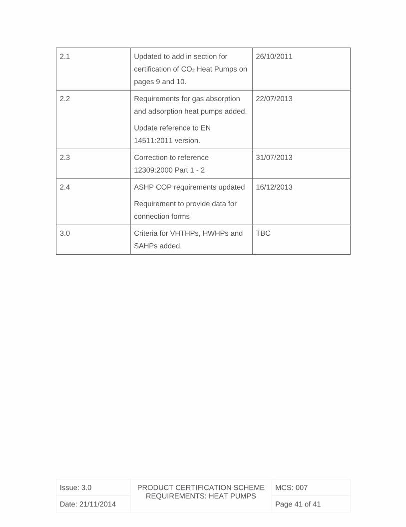
2.1 Updated to add in section for
certification of CO2 Heat Pumps on
pages 9 and 10.
26/10/2011
2.2 Requirements for gas absorption
and adsorption heat pumps added.
Update reference to EN
14511:2011 version.
22/07/2013
2.3 Correction to reference
12309:2000 Part 1 - 2
31/07/2013
2.4 ASHP COP requirements updated
Requirement to provide data for
connection forms
16/12/2013
3.0 Criteria for VHTHPs, HWHPs and
SAHPs added.
TBC