Embed Size (px)
Citation preview

GRUNDFOS INSTRUCTIONS
MGE model FService instructions, extended
s
Preface
These service instructions describe fault finding and correction of pumps with Grundfos motors, type MGE model F (hereafter called MGE-F).The service instructions are aimed at specially trained staff who are familiar with the service of electrotechnical products.The use of these service instructions presupposes knowledge of these documents:• Installation and operating instructions for MGE 160, MGE 180, advanced I/O• Installation and operating instructions for the pump system incorporating the motor.
These service instructions are published and updated in the Grundfos GTI database.
Symbols used in this document
NoteThese service instructions include only MGE-F and its user interfaces (control panel, R100 and PC Tool E-products). If the application includes other Grundfos products or systems, please refer to the service instructions of these products.
WarningIf these safety instructions are not observed, it may result in personal injury.
WarningIf these instructions are not observed, it may lead to electric shock with consequent risk of serious personal injury or death.
WarningOne or more components may be so hot that it may cause personal injury.
CautionIf these safety instructions are not observed, it may result in malfunction or damage to the equipment.
Note Notes or instructions that make the job easier and ensure safe operation.
2 / 61
Contents
1. Identification ............................................................................................................................... 41.1 Nameplates................................................................................................................................................. 41.2 Type key ..................................................................................................................................................... 51.3 Configuration .............................................................................................................................................. 52. General description.................................................................................................................... 62.1 Wiring diagrams and signal terminals......................................................................................................... 62.2 Control panel .............................................................................................................................................. 72.3 Indicator lights............................................................................................................................................. 82.4 Setting using the R100 remote control ....................................................................................................... 82.5 R100 menu structure .................................................................................................................................. 92.6 Alarms and warnings ................................................................................................................................ 102.7 Alarm overview ......................................................................................................................................... 103. Fault correction......................................................................................................................... 113.1 Safety instructions .................................................................................................................................... 113.2 Fault correction procedure........................................................................................................................ 113.3 The R100 as service tool .......................................................................................................................... 113.4 PC Tool E-products as service tool .......................................................................................................... 143.5 Operating conditions................................................................................................................................. 183.6 Fault correction using the indicator lights on the control panel................................................................. 193.7 Fault correction using alarm and warning codes ...................................................................................... 244. Checking the printed-circuit boards ....................................................................................... 284.1 Safety check of discharged intermediate circuit ....................................................................................... 284.2 Indicator lights on the control board.......................................................................................................... 294.3 Mains supply............................................................................................................................................. 324.4 Intermediate-circuit voltage....................................................................................................................... 324.5 Rectifier..................................................................................................................................................... 334.6 Insulation resistance (megging)................................................................................................................ 344.7 Winding resistance ................................................................................................................................... 345. Replacement of modules ......................................................................................................... 355.1 Replacement of varistor............................................................................................................................ 365.2 Replacement of control board................................................................................................................... 375.3 Replacement of rectifier board.................................................................................................................. 385.4 Replacement of inverter board ................................................................................................................. 415.5 Replacement of terminal box.................................................................................................................... 435.6 Calibration of terminal box ........................................................................................................................ 465.7 Configuration of terminal box.................................................................................................................... 476. Maintenance.............................................................................................................................. 486.1 Lubrication of motor bearings ................................................................................................................... 486.2 Replacement of motor bearings................................................................................................................ 497. Emergency operation (bypass) ............................................................................................... 517.1 Establishing emergency operation............................................................................................................ 517.2 Re-establishment of frequency converter operation ................................................................................. 528. Drawings and diagrams ........................................................................................................... 539. Winding resistances................................................................................................................. 5810. Tightening torques and lubrication ........................................................................................ 5910.1 Tightening torques.................................................................................................................................... 5910.2 Lubricating intervals and grease............................................................................................................... 5911. Service tools ............................................................................................................................. 60
3 / 61
1. Identification
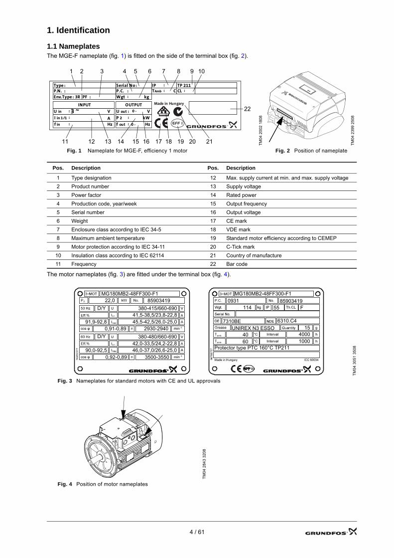
1.1 NameplatesThe MGE-F nameplate (fig. 1) is fitted on the side of the terminal box (fig. 2).
The motor nameplates (fig. 3) are fitted under the terminal box (fig. 4).
TM04
200
2 18
08
TM04
239
9 25
08
Fig. 1 Nameplate for MGE-F, efficiency 1 motor Fig. 2 Position of nameplate
Pos. Description Pos. Description
1 Type designation 12 Max. supply current at min. and max. supply voltage2 Product number 13 Supply voltage3 Power factor 14 Rated power4 Production code, year/week 15 Output frequency5 Serial number 16 Output voltage6 Weight 17 CE mark7 Enclosure class according to IEC 34-5 18 VDE mark8 Maximum ambient temperature 19 Standard motor efficiency according to CEMEP9 Motor protection according to IEC 34-11 20 C-Tick mark
10 Insulation class according to IEC 62114 21 Country of manufacture11 Frequency 22 Bar code
TM04
305
1 35
08
Fig. 3 Nameplates for standard motors with CE and UL approvals
TM04
284
3 32
08
Fig. 4 Position of motor nameplates
963 4
8 83
1
Type
Env.Type : 3RP.N.
Serial No :P.C.
PF :
U in
I in 1/1
f in
OUTPUT
U out
P 2
f out
Wgt
V
kW
V
AHz
: 0 -
: kg
3 ~
:
Made in HungaryINPUT
::
Hz
:
:
:
:
:
CLTP 211
TAmb
IP: C:
:
0 -
1 2 3 4 5 6 7 8 9 10
11 12 13 14 15 16 17 19 20 21
22
18
MG180MB2-48FF300-F122,0 85903419
D/Y 380-415/660-69041,5-38,5/23,8-22,8
91,9-92,8 45,5-42,5/26,0-25,00,91-0,89 2930-2940
D/Y 380-480/660-69042,0-33,5/24,2-22,846,0-37,0/26,6-25,0
3500-355090,0-92,5
0,92-0,89
MG180MB2-48FF300-F1
4000
85903419
10004060
UNIREX N3 ESSO6310.C47310BE
15
Protector type PTC 160°C TP211
114 55 F0931
4 / 61
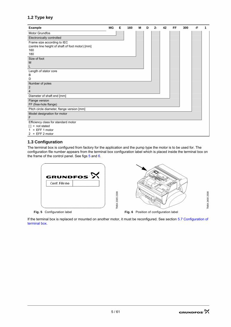
1.2 Type key
1.3 ConfigurationThe terminal box is configured from factory for the application and the pump type the motor is to be used for. The configuration file number appears from the terminal box configuration label which is placed inside the terminal box on the frame of the control panel. See figs 5 and 6.
If the terminal box is replaced or mounted on another motor, it must be reconfigured. See section 5.7 Configuration of terminal box.
Example MG E 160 M D 2- 42 FF 300 -F 1
Motor GrundfosElectronically controlledFrame size according to IEC(centre line height of shaft of foot motor) [mm]160180Size of footMLLength of stator coreBDNumber of poles24Diameter of shaft end [mm]Flange versionFF (free-hole flange)Pitch circle diameter, flange version [mm]Model designation for motorFEfficiency class for standard motor[ ] = not stated1 = EFF 1 motor2 = EFF 2 motor
TM04
230
5 23
08
TM04
240
0 25
08
Fig. 5 Configuration label Fig. 6 Position of configuration label
5 / 61
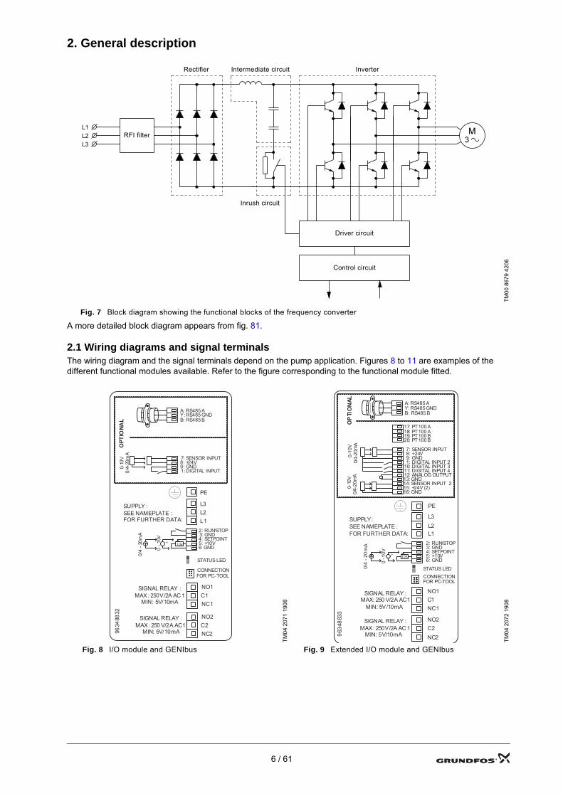
2. General description
Fig. 7 Block diagram showing the functional blocks of the frequency converter
A more detailed block diagram appears from fig. 81.
2.1 Wiring diagrams and signal terminalsThe wiring diagram and the signal terminals depend on the pump application. Figures 8 to 11 are examples of the different functional modules available. Refer to the figure corresponding to the functional module fitted.
TM00
867
9 42
06
TM04
207
1 19
08
TM04
207
2 19
08
Fig. 8 I/O module and GENIbus Fig. 9 Extended I/O module and GENIbus
Inrush circuit
RFI filter
Rectifier Intermediate circuit Inverter
Driver circuit
Control circuit
9634
8832
NC1C1NO1SIGNAL RELAY :
MAX: 250V/2A AC 1MIN: 5V/10mA
CONNECTIONFOR PC-TOOL
NC2C2NO2SIGNAL RELAY :
MAX: 250 V/2A AC1MIN: 5V/10mA
STATUS LED
OPTIONAL
7: SENSOR INPUT8: +24V9: GND1: DIGITAL INPUT
0-10
V 0/
4-20
mA
A: RS485 AY: RS485 GNDB: RS485 B
0 -1
0V+
2: RUN/STOP3: GND4: SETPOINT5: +10V6: GND
10k
0/4
-20m
A
SUPPLY :SEE NAMEPLATE :FOR FURTHER DATA: L1
L2L3
PE
OPTIONAL
9634
8833
CONNECTIONFOR PC-TOOL
NC1C1NO1SIGNAL RELAY :
MAX: 250 V/2A AC1MIN: 5V/10mA
NC2C2NO2SIGNAL RELAY :
MAX: 250V/2A AC 1MIN: 5V/10mA
L3L2L1
SUPPLY:SEE NAMEPLATE :FOR FURTHER DATA:
17: PT100 A18: PT100 A19: PT100 B20: PT100 B
STATUS LED
7: SENSOR INPUT8: +24V9: GND0-
10V
0/4-
20m
A
1: DIGITAL INPUT 210: DIGITAL INPUT 311: DIGITAL INPUT 412: ANALOG OUTPUT13: GND14: SENSOR INPUT 215: +24V (2)16: GND
0-10
V0/
4-20
mA
A: RS485 AY: RS485 GNDB: RS485 B
+
0- 1
0V
0/4
-20
mA 2: RUN/STOP
3: GND4: SETPOINT5: +10V6: GND
10k
PE
6 / 61

2.2 Control panel
2.2.1 OperationThe motor control panel has the following buttons and indicator lights:• Buttons and for setting of setpoint.• Light fields, yellow, for indication of setpoint.• Indicator lights, green (operation) and red (fault).Switch control mode by pressing in this sequence:• constant pressure, • proportional pressure, .Set the pump head by pressing or .The light fields of the control panel will indicate the set head (setpoint).
TM04
207
3 19
08
TM04
207
4 19
08
Fig. 10 TPED module Fig. 11 Multi-E module
TM02
851
3 03
04
TM03
012
6 41
04
Fig. 12 CRE and TPE, TPED Fig. 13 TPE, TPED Series 2000
9634
8945
NC1C1NO1SIGNAL RELAY :
MAX: 250 V/2A AC1MIN: 5V/10mA
CONNECTIONFOR PC-TOOL
NC2C2NO2SIGNAL RELAY :
MAX: 250V/2A AC 1MIN: 5V/10mA
TPED
0 -1
0V+
2: RUN/STOP3: GND4: SETPOINT5: +10V6: GND
10k
0/4
-20m
A
SUPPLY :SEE NAMEPLATEFOR FURTHER DATA L1
L2L3
PE
A: RS485AY: RS485 GNDB: RS485B
7: SENSOR INPUT8: +24V9: GND1: DIGITAL INPUT 1
0-10
V
0/4-
20m
A
CONNECTION FORTWIN PUMP
TWIN PUMP SWITCH
STATUS LED
9634
8946
NC1C1NO1SIGNAL RELAY :
MAX: 250 V/2A AC1MIN: 5V/10mA
CONNECTIONFOR PC-TOOL
NC2C2NO2SIGNAL RELAY :
MAX: 250 V/2A AC1MIN: 5V/10mA
Multi-E
0 -1
0V+
2: RUN/STOP3: GND4: SETPOINT5: +10V6: GND
10k
0/4
-20m
A
SUPPLY :SEE NAMEPLATEFOR FURTHER DATA L1
L2L3
PE
A: RS485A (ext. bus)Y: RS485 GND (ext. bus)B: RS485B (ext. bus)
A1: RS485A (int. bus)Y: RS485 GND (int. bus)
B1: RS485B (int. bus)
7: SENSOR INPUT8: +24V9: GND1: DIGITAL INPUT 1
0-10
V 0/
4-20
mA
STATUS LED
7 / 61
2.3 Indicator lights
2.3.1 Indicator lights on the control panelThe indicator lights on the control panel show the MGE-F motor's operating and alarm condition.
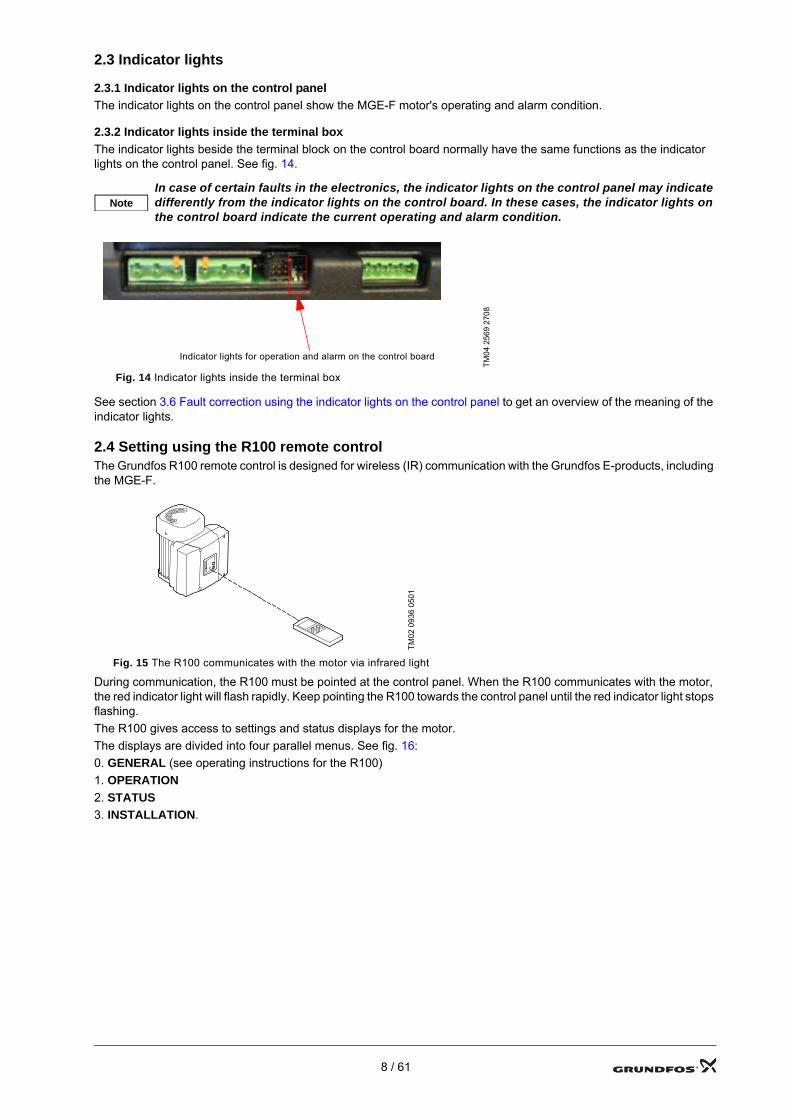
2.3.2 Indicator lights inside the terminal boxThe indicator lights beside the terminal block on the control board normally have the same functions as the indicator lights on the control panel. See fig. 14.
See section 3.6 Fault correction using the indicator lights on the control panel to get an overview of the meaning of the indicator lights.
2.4 Setting using the R100 remote controlThe Grundfos R100 remote control is designed for wireless (IR) communication with the Grundfos E-products, including the MGE-F.
Fig. 15 The R100 communicates with the motor via infrared light
During communication, the R100 must be pointed at the control panel. When the R100 communicates with the motor, the red indicator light will flash rapidly. Keep pointing the R100 towards the control panel until the red indicator light stops flashing.The R100 gives access to settings and status displays for the motor.The displays are divided into four parallel menus. See fig. 16:0. GENERAL (see operating instructions for the R100)1. OPERATION2. STATUS3. INSTALLATION.
NoteIn case of certain faults in the electronics, the indicator lights on the control panel may indicate differently from the indicator lights on the control board. In these cases, the indicator lights on the control board indicate the current operating and alarm condition.
TM04
256
9 27
08
Fig. 14 Indicator lights inside the terminal box
TM02
093
6 05
01
Indicator lights for operation and alarm on the control board
8 / 61
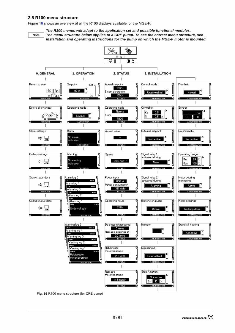
2.5 R100 menu structureFigure 16 shows an overview of all the R100 displays available for the MGE-F.
NoteThe R100 menus will adapt to the application set and possible functional modules.The menu structure below applies to a CRE pump. To see the correct menu structure, see installation and operating instructions for the pump on which the MGE-F motor is mounted.
0. GENERAL 1. OPERATION 2. STATUS 3. INSTALLATION
Fig. 16 R100 menu structure (for CRE pump)
9 / 61
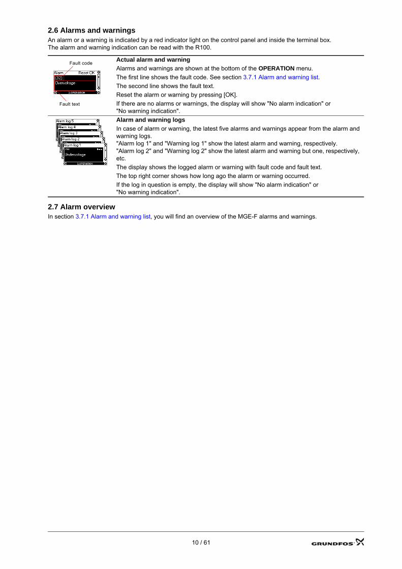
2.6 Alarms and warningsAn alarm or a warning is indicated by a red indicator light on the control panel and inside the terminal box. The alarm and warning indication can be read with the R100.
2.7 Alarm overviewIn section 3.7.1 Alarm and warning list, you will find an overview of the MGE-F alarms and warnings.
Actual alarm and warningAlarms and warnings are shown at the bottom of the OPERATION menu.The first line shows the fault code. See section 3.7.1 Alarm and warning list.The second line shows the fault text.Reset the alarm or warning by pressing [OK].If there are no alarms or warnings, the display will show "No alarm indication" or "No warning indication".Alarm and warning logsIn case of alarm or warning, the latest five alarms and warnings appear from the alarm and warning logs. "Alarm log 1" and "Warning log 1" show the latest alarm and warning, respectively."Alarm log 2" and "Warning log 2" show the latest alarm and warning but one, respectively, etc.The display shows the logged alarm or warning with fault code and fault text.The top right corner shows how long ago the alarm or warning occurred.If the log in question is empty, the display will show "No alarm indication" or "No warning indication".
Fault code
Fault text
10 / 61
3. Fault correction
3.1 Safety instructions
3.2 Fault correction procedureFault correction is based on these sections in this order:• 3.5 Operating conditions• 3.6 Fault correction using the indicator lights on the control panel• 3.7 Fault correction using alarm and warning codes• 10. Tightening torques and lubrication.The necessary tools for the fault correction can be seen in section 11. Service tools.
3.3 The R100 as service toolWhen set to "Service mode", the R100 can be used for service purposes on the product in question.
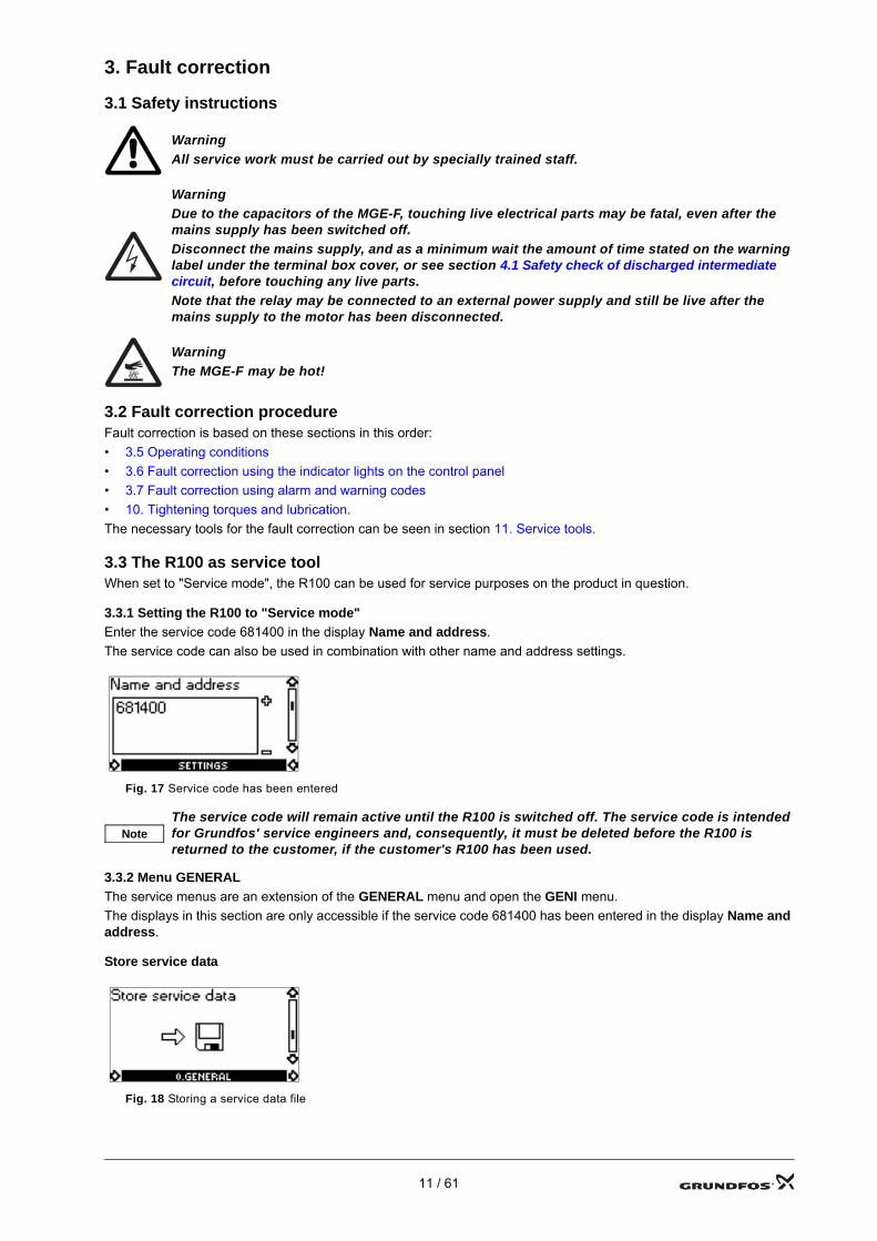
3.3.1 Setting the R100 to "Service mode"Enter the service code 681400 in the display Name and address.The service code can also be used in combination with other name and address settings.
Fig. 17 Service code has been entered
3.3.2 Menu GENERALThe service menus are an extension of the GENERAL menu and open the GENI menu.The displays in this section are only accessible if the service code 681400 has been entered in the display Name and address.
Store service data
Fig. 18 Storing a service data file
WarningAll service work must be carried out by specially trained staff.
WarningDue to the capacitors of the MGE-F, touching live electrical parts may be fatal, even after the mains supply has been switched off.Disconnect the mains supply, and as a minimum wait the amount of time stated on the warning label under the terminal box cover, or see section 4.1 Safety check of discharged intermediate circuit, before touching any live parts.Note that the relay may be connected to an external power supply and still be live after the mains supply to the motor has been disconnected.
WarningThe MGE-F may be hot!
NoteThe service code will remain active until the R100 is switched off. The service code is intended for Grundfos' service engineers and, consequently, it must be deleted before the R100 is returned to the customer, if the customer's R100 has been used.
11 / 61
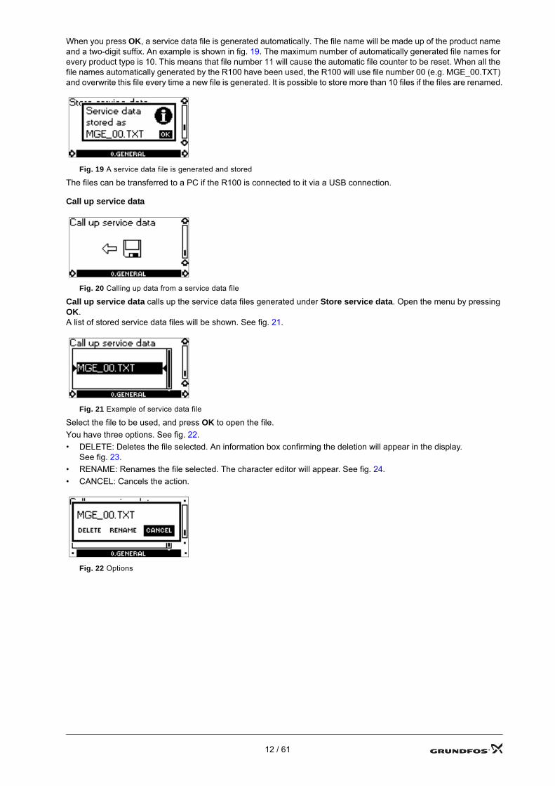
When you press OK, a service data file is generated automatically. The file name will be made up of the product name and a two-digit suffix. An example is shown in fig. 19. The maximum number of automatically generated file names for every product type is 10. This means that file number 11 will cause the automatic file counter to be reset. When all the file names automatically generated by the R100 have been used, the R100 will use file number 00 (e.g. MGE_00.TXT) and overwrite this file every time a new file is generated. It is possible to store more than 10 files if the files are renamed.
Fig. 19 A service data file is generated and stored
The files can be transferred to a PC if the R100 is connected to it via a USB connection.
Call up service data
Fig. 20 Calling up data from a service data file
Call up service data calls up the service data files generated under Store service data. Open the menu by pressing OK.A list of stored service data files will be shown. See fig. 21.
Fig. 21 Example of service data file
Select the file to be used, and press OK to open the file.You have three options. See fig. 22.• DELETE: Deletes the file selected. An information box confirming the deletion will appear in the display.
See fig. 23.• RENAME: Renames the file selected. The character editor will appear. See fig. 24.• CANCEL: Cancels the action.
Fig. 22 Options
12 / 61
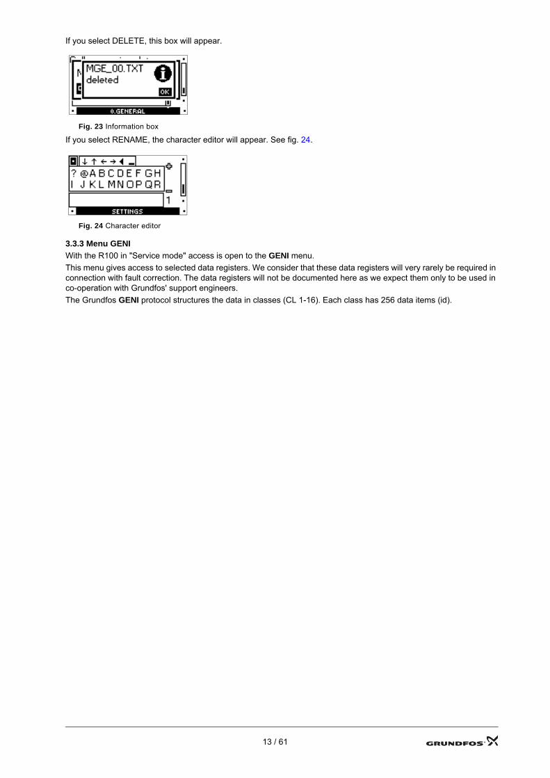
If you select DELETE, this box will appear.
Fig. 23 Information box
If you select RENAME, the character editor will appear. See fig. 24.
Fig. 24 Character editor
3.3.3 Menu GENIWith the R100 in "Service mode" access is open to the GENI menu.This menu gives access to selected data registers. We consider that these data registers will very rarely be required in connection with fault correction. The data registers will not be documented here as we expect them only to be used in co-operation with Grundfos' support engineers.The Grundfos GENI protocol structures the data in classes (CL 1-16). Each class has 256 data items (id).
13 / 61

3.4 PC Tool E-products as service tool
3.4.1 PC Tool E-productsThe PC Tool E-products is a software tool which enables communication with GENIbus products from a PC using Microsoft Windows.The PC Tool E-products can be used for fault correction of E-products, including the MGE-F.
3.4.2 Acquisition of PC Tool E-productsThe PC Tool E-products can be acquired via GTI, which is a Lotus® Notes® database.
3.4.3 Connecting the PC to the MGE-FA Grundfos PC Tool Link is used for the physical connection between the PC and the MGE-F. The PC Tool Link converts RS-485 used by the MGE-F to RS-232 or USB used by the PC. The PC Tool Link also provides galvanic separation between the MGE-F and the PC.
Connect the TTL cable to the service plug in the MGE-F. See fig. 26.
3.4.4 Using the PC Tool E-products on pumps running duty/standbyThe MGE-F enables the connection of PC Tool E-products to a pump running duty/standby without having to deactivate the function temporarily. This was not possible in previous versions of MGE.
Fig. 25 Example of connection of a PC to the MGE-F using a RS-232 cableTM
04 2
569
2708
Fig. 26 Plug for connection of PC Tool Link
5 V cable
RS-232 null modem
PC Tool Link TTL cable
Plug for connection of PC Tool Link
14 / 61
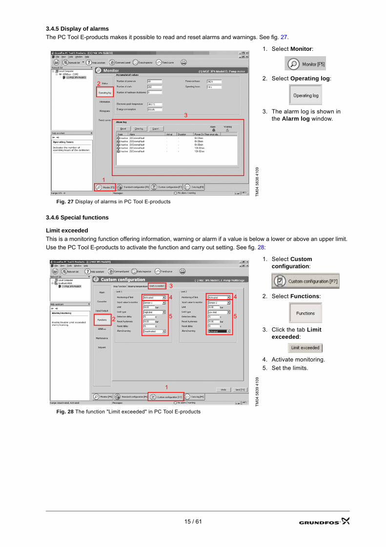
3.4.5 Display of alarmsThe PC Tool E-products makes it possible to read and reset alarms and warnings. See fig. 27.
3.4.6 Special functions
Limit exceededThis is a monitoring function offering information, warning or alarm if a value is below a lower or above an upper limit.Use the PC Tool E-products to activate the function and carry out setting. See fig. 28:
TM04
583
8 41
09
1. Select Monitor:
2. Select Operating log:
3. The alarm log is shown in the Alarm log window.
Fig. 27 Display of alarms in PC Tool E-products
TM04
583
9 41
091. Select Custom
configuration:
2. Select Functions:
3. Click the tab Limit exceeded:
4. Activate monitoring.5. Set the limits.
Fig. 28 The function "Limit exceeded" in PC Tool E-products
1
2
3
1
2
3
4
5
4
5
15 / 61
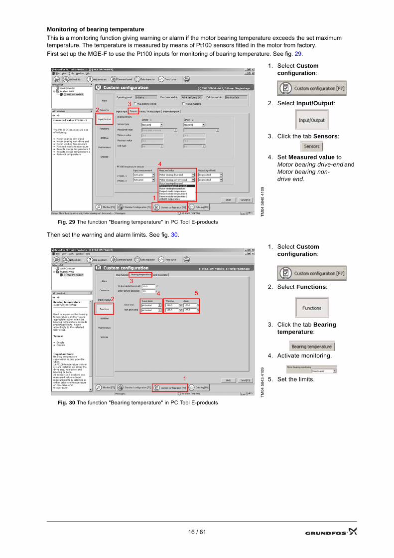
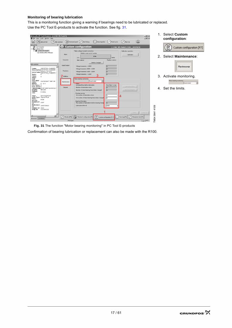
Monitoring of bearing temperatureThis is a monitoring function giving warning or alarm if the motor bearing temperature exceeds the set maximum temperature. The temperature is measured by means of Pt100 sensors fitted in the motor from factory.First set up the MGE-F to use the Pt100 inputs for monitoring of bearing temperature. See fig. 29.
Then set the warning and alarm limits. See fig. 30.
TM04
584
0 41
09
1. Select Custom configuration:
2. Select Input/Output:
3. Click the tab Sensors:
4. Set Measured value to Motor bearing drive-end and Motor bearing non-drive end.
Fig. 29 The function "Bearing temperature" in PC Tool E-products
TM04
584
3 41
09
1. Select Custom configuration:
2. Select Functions:
3. Click the tab Bearing temperature:
4. Activate monitoring.
5. Set the limits.
Fig. 30 The function "Bearing temperature" in PC Tool E-products
1
23
4
1
2
3
54
16 / 61
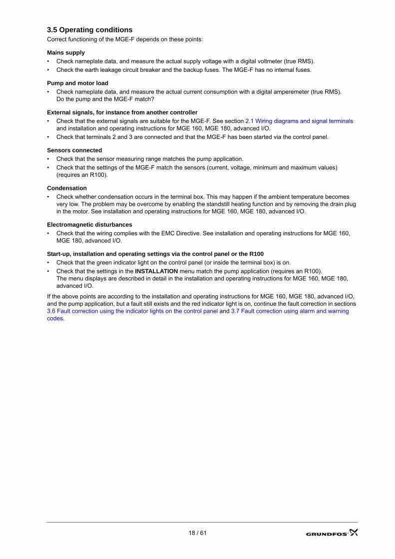
Monitoring of bearing lubricationThis is a monitoring function giving a warning if bearings need to be lubricated or replaced.Use the PC Tool E-products to activate the function. See fig. 31.
Confirmation of bearing lubrication or replacement can also be made with the R100.
TM04
584
1 41
09
1. Select Custom configuration:
2. Select Maintenance:
3. Activate monitoring.
4. Set the limits.
Fig. 31 The function "Motor bearing monitoring" in PC Tool E-products
1
2 3
4
17 / 61
3.5 Operating conditionsCorrect functioning of the MGE-F depends on these points:
Mains supply• Check nameplate data, and measure the actual supply voltage with a digital voltmeter (true RMS).• Check the earth leakage circuit breaker and the backup fuses. The MGE-F has no internal fuses.
Pump and motor load• Check nameplate data, and measure the actual current consumption with a digital amperemeter (true RMS).
Do the pump and the MGE-F match?
External signals, for instance from another controller• Check that the external signals are suitable for the MGE-F. See section 2.1 Wiring diagrams and signal terminals
and installation and operating instructions for MGE 160, MGE 180, advanced I/O.• Check that terminals 2 and 3 are connected and that the MGE-F has been started via the control panel.
Sensors connected• Check that the sensor measuring range matches the pump application.• Check that the settings of the MGE-F match the sensors (current, voltage, minimum and maximum values)
(requires an R100).
Condensation• Check whether condensation occurs in the terminal box. This may happen if the ambient temperature becomes
very low. The problem may be overcome by enabling the standstill heating function and by removing the drain plug in the motor. See installation and operating instructions for MGE 160, MGE 180, advanced I/O.
Electromagnetic disturbances• Check that the wiring complies with the EMC Directive. See installation and operating instructions for MGE 160,
MGE 180, advanced I/O.
Start-up, installation and operating settings via the control panel or the R100• Check that the green indicator light on the control panel (or inside the terminal box) is on.• Check that the settings in the INSTALLATION menu match the pump application (requires an R100).
The menu displays are described in detail in the installation and operating instructions for MGE 160, MGE 180, advanced I/O.
If the above points are according to the installation and operating instructions for MGE 160, MGE 180, advanced I/O, and the pump application, but a fault still exists and the red indicator light is on, continue the fault correction in sections 3.6 Fault correction using the indicator lights on the control panel and 3.7 Fault correction using alarm and warning codes.
18 / 61
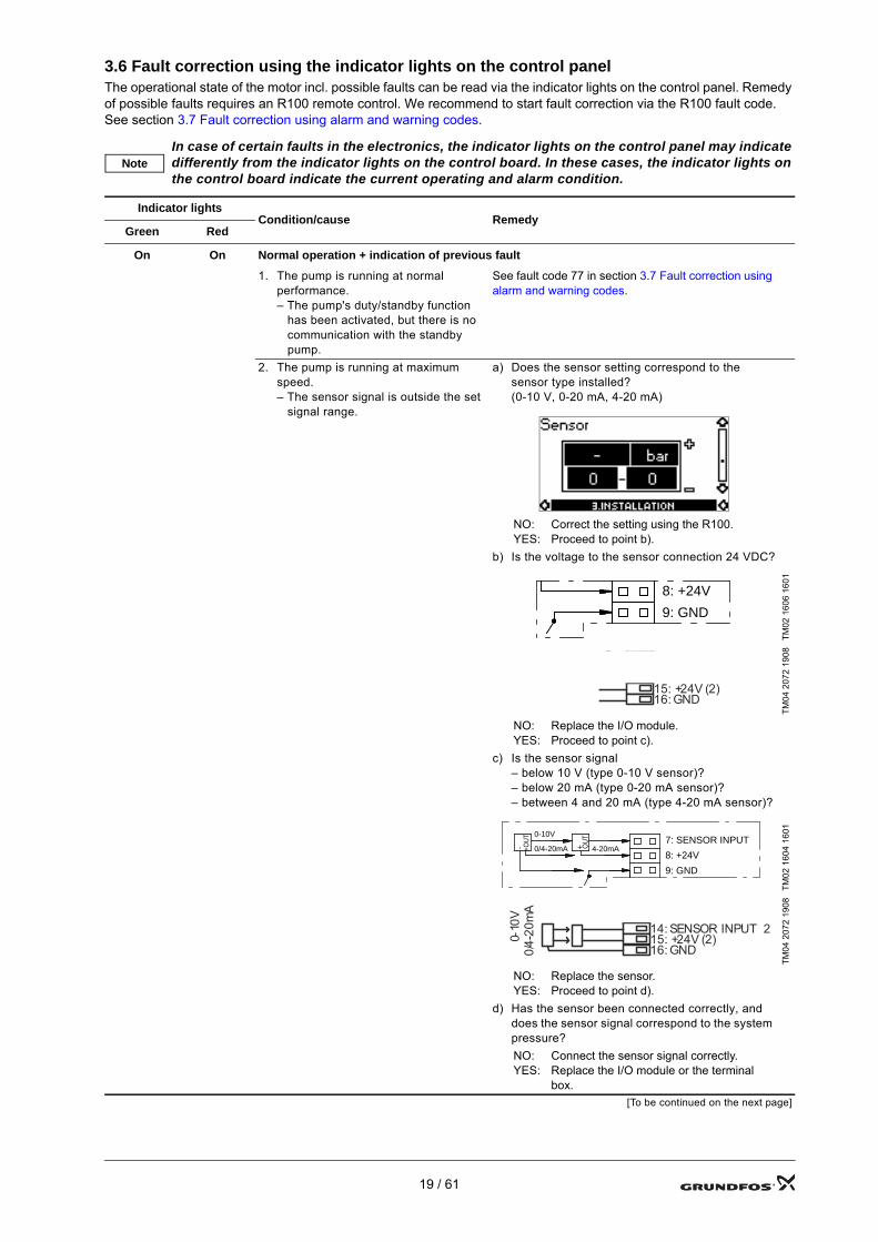
3.6 Fault correction using the indicator lights on the control panelThe operational state of the motor incl. possible faults can be read via the indicator lights on the control panel. Remedy of possible faults requires an R100 remote control. We recommend to start fault correction via the R100 fault code. See section 3.7 Fault correction using alarm and warning codes.
NoteIn case of certain faults in the electronics, the indicator lights on the control panel may indicate differently from the indicator lights on the control board. In these cases, the indicator lights on the control board indicate the current operating and alarm condition.
Indicator lightsCondition/cause Remedy
Green Red
On On Normal operation + indication of previous fault
1. The pump is running at normal performance.– The pump's duty/standby function
has been activated, but there is no communication with the standby pump.
See fault code 77 in section 3.7 Fault correction using alarm and warning codes.
2. The pump is running at maximum speed.– The sensor signal is outside the set
signal range.
a) Does the sensor setting correspond to the sensor type installed?(0-10 V, 0-20 mA, 4-20 mA)
NO:YES:
Correct the setting using the R100.Proceed to point b).
b) Is the voltage to the sensor connection 24 VDC?
TM02
160
6 16
01TM
04 2
072
1908
NO:YES:
Replace the I/O module.Proceed to point c).
c) Is the sensor signal– below 10 V (type 0-10 V sensor)?– below 20 mA (type 0-20 mA sensor)?– between 4 and 20 mA (type 4-20 mA sensor)?
TM02
160
4 16
01TM
04 2
072
1908
NO:YES:
Replace the sensor.Proceed to point d).
d) Has the sensor been connected correctly, and does the sensor signal correspond to the system pressure?NO:YES:
Connect the sensor signal correctly.Replace the I/O module or the terminal box.
[To be continued on the next page]
8: +24V
9: GND
12: ANALOG OUTPUT13: GND14: SENSOR INPUT 215: +24V (2)16: GND
0-10
V0/
4-20
mA
7: SENSOR INPUT
8: +24V
9: GND
4-20mA+ OU
T0-10V
0/4-20mA - +OU
T
G U12: ANALOG OUTPUT13: GND14: SENSOR INPUT 215: +24V (2)16: GND
0-10
V0/
4-20
mA
19 / 61
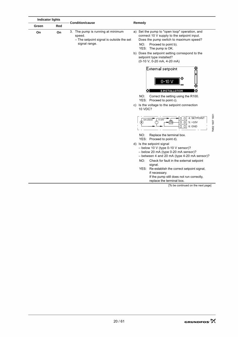
On On 3. The pump is running at minimum speed.– The setpoint signal is outside the set
signal range.
a) Set the pump to "open loop" operation, and connect 10 V supply to the setpoint input.Does the pump switch to maximum speed?NO:YES:
Proceed to point b).The pump is OK.
b) Does the setpoint setting correspond to the setpoint type installed?(0-10 V, 0-20 mA, 4-20 mA)
NO:YES:
Correct the setting using the R100.Proceed to point c).
c) Is the voltage to the setpoint connection 10 VDC?
TM02
160
7 16
01
NO:YES:
Replace the terminal box.Proceed to point d).
d) Is the setpoint signal– below 10 V (type 0-10 V sensor)?– below 20 mA (type 0-20 mA sensor)?– between 4 and 20 mA (type 4-20 mA sensor)?NO:
YES:
Check for fault in the external setpoint signal. Re-establish the correct setpoint signal, if necessary.If the pump still does not run correctly, replace the terminal box.
[To be continued on the next page]
Indicator lightsCondition/cause Remedy
Green Red
0-10V+-
0/4-20mA10K
4: SETPOINT
5: +10V
6: GND
20 / 61
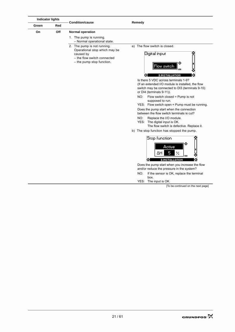
On Off Normal operation
1. The pump is running.– Normal operational state.
2. The pump is not running.Operational stop which may be caused by– the flow switch connected– the pump stop function.
a) The flow switch is closed.
Is there 5 VDC across terminals 1-9? (If an extended I/O module is installed, the flow switch may be connected to DI3 (terminals 9-10) or DI4 (terminals 9-11)).NO:
YES:
Flow switch closed = Pump is not supposed to run.Flow switch open = Pump must be running.
Does the pump start when the connection between the flow switch terminals is cut?NO:YES:
Replace the I/O module.The digital input is OK. The flow switch is defective. Replace it.
b) The stop function has stopped the pump.
Does the pump start when you increase the flow and/or reduce the pressure in the system?NO:
YES:
If the sensor is OK, replace the terminal box.The input is OK.
[To be continued on the next page]
Indicator lightsCondition/cause Remedy
Green Red
21 / 61
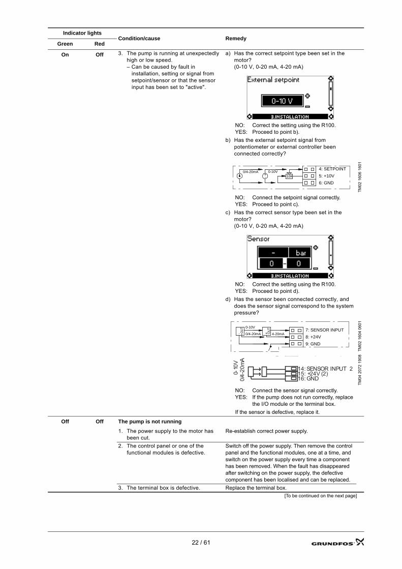
On Off 3. The pump is running at unexpectedly high or low speed.– Can be caused by fault in
installation, setting or signal from setpoint/sensor or that the sensor input has been set to "active".
a) Has the correct setpoint type been set in the motor? (0-10 V, 0-20 mA, 4-20 mA)
NO:YES:
Correct the setting using the R100.Proceed to point b).
b) Has the external setpoint signal from potentiometer or external controller been connected correctly?
TM02
160
6 16
01
NO:YES:
Connect the setpoint signal correctly.Proceed to point c).
c) Has the correct sensor type been set in the motor?(0-10 V, 0-20 mA, 4-20 mA)
NO:YES:
Correct the setting using the R100.Proceed to point d).
d) Has the sensor been connected correctly, and does the sensor signal correspond to the system pressure?
TM02
160
4 06
01TM
04 2
072
1908
NO:YES:
Connect the sensor signal correctly.If the pump does not run correctly, replace the I/O module or the terminal box.
If the sensor is defective, replace it.
Off Off The pump is not running
1. The power supply to the motor has been cut.
Re-establish correct power supply.
2. The control panel or one of the functional modules is defective.
Switch off the power supply. Then remove the control panel and the functional modules, one at a time, and switch on the power supply every time a component has been removed. When the fault has disappeared after switching on the power supply, the defective component has been localised and can be replaced.
3. The terminal box is defective. Replace the terminal box. [To be continued on the next page]
Indicator lightsCondition/cause Remedy
Green Red
0-10V+-
0/4-20mA10K
4: SETPOINT
5: +10V
6: GND
7: SENSOR INPUT
8: +24V
9: GND
4-20mA+ OU
T0-10V
0/4-20mA - +OU
T
G U12: ANALOG OUTPUT13: GND14: SENSOR INPUT 215: +24V (2)16: GND
0-10
V0/
4-20
mA
22 / 61
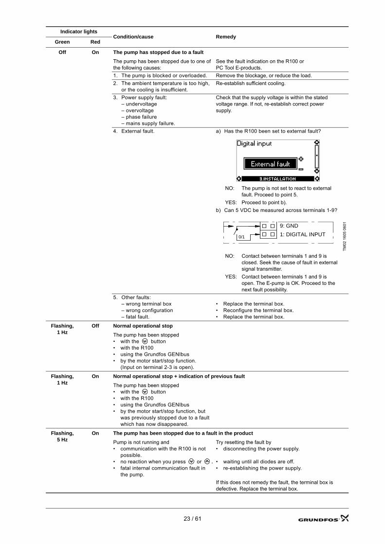
Off On The pump has stopped due to a fault
The pump has been stopped due to one of the following causes:
See the fault indication on the R100 or PC Tool E-products.
1. The pump is blocked or overloaded. Remove the blockage, or reduce the load.2. The ambient temperature is too high,
or the cooling is insufficient.Re-establish sufficient cooling.
3. Power supply fault:– undervoltage– overvoltage– phase failure– mains supply failure.
Check that the supply voltage is within the stated voltage range. If not, re-establish correct power supply.
4. External fault. a) Has the R100 been set to external fault?
NO: The pump is not set to react to external fault. Proceed to point 5.
YES: Proceed to point b).b) Can 5 VDC be measured across terminals 1-9?
TM02
160
5 06
01
NO: Contact between terminals 1 and 9 is closed. Seek the cause of fault in external signal transmitter.
YES: Contact between terminals 1 and 9 is open. The E-pump is OK. Proceed to the next fault possibility.
5. Other faults:– wrong terminal box– wrong configuration– fatal fault.
• Replace the terminal box.• Reconfigure the terminal box.• Replace the terminal box.
Flashing, 1 Hz
Off Normal operational stop
The pump has been stopped• with the button• with the R100• using the Grundfos GENIbus• by the motor start/stop function.
(Input on terminal 2-3 is open).
Flashing, 1 Hz
On Normal operational stop + indication of previous fault
The pump has been stopped• with the button• with the R100• using the Grundfos GENIbus• by the motor start/stop function, but
was previously stopped due to a fault which has now disappeared.
Flashing, 5 Hz
On The pump has been stopped due to a fault in the product
Pump is not running and• communication with the R100 is not
possible.• no reaction when you press or .• fatal internal communication fault in
the pump.
Try resetting the fault by• disconnecting the power supply.
• waiting until all diodes are off.• re-establishing the power supply.
If this does not remedy the fault, the terminal box is defective. Replace the terminal box.
Indicator lightsCondition/cause Remedy
Green Red
9: GND
1: DIGITAL INPUT0/1
23 / 61
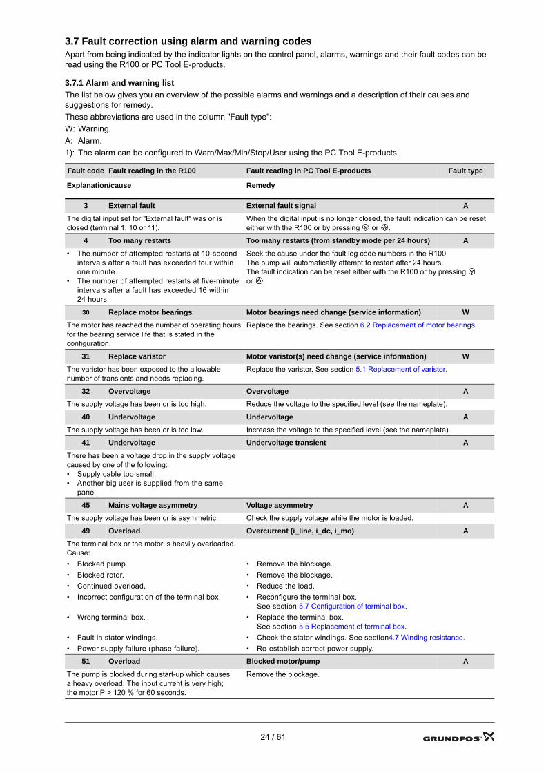
3.7 Fault correction using alarm and warning codesApart from being indicated by the indicator lights on the control panel, alarms, warnings and their fault codes can be read using the R100 or PC Tool E-products.
3.7.1 Alarm and warning listThe list below gives you an overview of the possible alarms and warnings and a description of their causes and suggestions for remedy.These abbreviations are used in the column "Fault type":W: Warning.A: Alarm.1): The alarm can be configured to Warn/Max/Min/Stop/User using the PC Tool E-products.
Fault code Fault reading in the R100 Fault reading in PC Tool E-products Fault type
Explanation/cause Remedy
3 External fault External fault signal A
The digital input set for "External fault" was or is closed (terminal 1, 10 or 11).
When the digital input is no longer closed, the fault indication can be reset either with the R100 or by pressing or .
4 Too many restarts Too many restarts (from standby mode per 24 hours) A
• The number of attempted restarts at 10-second intervals after a fault has exceeded four within one minute.
• The number of attempted restarts at five-minute intervals after a fault has exceeded 16 within 24 hours.
Seek the cause under the fault log code numbers in the R100.The pump will automatically attempt to restart after 24 hours.The fault indication can be reset either with the R100 or by pressing or .
30 Replace motor bearings Motor bearings need change (service information) W
The motor has reached the number of operating hours for the bearing service life that is stated in the configuration.
Replace the bearings. See section 6.2 Replacement of motor bearings.
31 Replace varistor Motor varistor(s) need change (service information) W
The varistor has been exposed to the allowable number of transients and needs replacing.
Replace the varistor. See section 5.1 Replacement of varistor.
32 Overvoltage Overvoltage A
The supply voltage has been or is too high. Reduce the voltage to the specified level (see the nameplate).
40 Undervoltage Undervoltage A
The supply voltage has been or is too low. Increase the voltage to the specified level (see the nameplate).
41 Undervoltage Undervoltage transient A
There has been a voltage drop in the supply voltage caused by one of the following:• Supply cable too small.• Another big user is supplied from the same
panel.
45 Mains voltage asymmetry Voltage asymmetry A
The supply voltage has been or is asymmetric. Check the supply voltage while the motor is loaded.
49 Overload Overcurrent (i_line, i_dc, i_mo) A
The terminal box or the motor is heavily overloaded.Cause:• Blocked pump. • Remove the blockage.• Blocked rotor. • Remove the blockage.• Continued overload. • Reduce the load.• Incorrect configuration of the terminal box. • Reconfigure the terminal box.
See section 5.7 Configuration of terminal box.• Wrong terminal box. • Replace the terminal box.
See section 5.5 Replacement of terminal box.• Fault in stator windings. • Check the stator windings. See section4.7 Winding resistance.• Power supply failure (phase failure). • Re-establish correct power supply.
51 Overload Blocked motor/pump A
The pump is blocked during start-up which causes a heavy overload. The input current is very high; the motor P > 120 % for 60 seconds.
Remove the blockage.
24 / 61
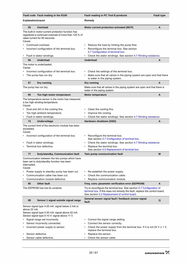
55 Overload Motor current protection activated (MCP) A
The built-in motor-current protection function has registered a continued overload of more than 125 % of rated current for 60 seconds.Cause:• Continued overload. • Reduce the load by limiting the pump flow.• Incorrect configuration of the terminal box. • Reconfigure the terminal box. See section
5.7 Configuration of terminal box.• Fault in stator windings. • Check the stator windings. See section 4.7 Winding resistance.
56 Underload Underload A
The motor is underloaded.Cause:• Incorrect configuration of the terminal box. • Check the settings of the terminal box.• The pump has run dry. • Make sure that all valves in the piping system are open and that there
is water in the piping system.
57 Dry running Dry running A
The pump has run dry. Make sure that all valves in the piping system are open and that there is water in the piping system.
65 Too high motor temperature Motor temperature A
The temperature sensor in the motor has measured a too high winding temperature.Cause:• Dust and dirt in the cooling fins. • Clean the cooling fins.• Too high ambient temperature. • Improve the cooling.• Fault in stator windings. • Check the stator windings. See section 4.7 Winding resistance.
73 Undervoltage Hardware shutdown (HSD) A
The current limit of the electronic module has been exceeded.Cause:• Incorrect configuration of the terminal box. • Reconfigure the terminal box.
See section 5.7 Configuration of terminal box.• Fault in stator windings. • Check the stator windings. See section 4.7 Winding resistance.• Terminal box defective. • Replace the terminal box.
See section 5.5 Replacement of terminal box.
77 Duty/standby, Communication fault Twin pump communication fault W
Communication between the two pumps which have been set to duty/standby function has been interrupted.Cause:• Power supply to standby pump has been cut. • Re-establish the power supply.• Communication cable has been cut. • Check the communication cable.• Communication module defective. • Replace communication module.
85 Other fault Freq. conv. parameter verification error (EEPROM) A
The EEPROM has lost its contents. Try to reconfigure the terminal box. See section 5.7 Configuration of terminal box. If this does not remedy the fault, replace the control board. See section 5.2 Replacement of control board.
88 Sensor 1 signal outside signal range General sensor signal fault / feedback sensor signal fault 1)
Sensor signal type 4-20 mA: signal below 2 mA or above 22 mA.Sensor signal type 0-20 mA: signal above 22 mA.Sensor signal type 0-10 V: signal above 11 V.• Signal range set incorrectly. • Correct the signal range setting.• Sensor incorrectly connected. • Connect the sensor correctly.• Incorrect power supply to sensor. • Check the power supply from the terminal box. If it is not 24 V ± 1 V,
replace the terminal box.• Sensor defective. • Replace the sensor.• Sensor cable defective. • Check the sensor cable.
Fault code Fault reading in the R100 Fault reading in PC Tool E-products Fault type
Explanation/cause Remedy
25 / 61
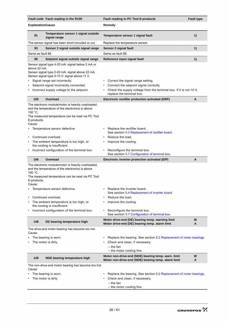
91 Temperature sensor 1 signal outside signal range Temperature sensor 1 signal fault 1)
The sensor signal has been short-circuited or cut. Replace the temperature sensor.
93 Sensor 2 signal outside signal range Sensor 2 signal fault 1)
Same as fault 88. Same as fault 88.
96 Setpoint signal outside signal range Reference input signal fault 1)
Sensor signal type 4-20 mA: signal below 2 mA or above 22 mA.Sensor signal type 0-20 mA: signal above 22 mA.Sensor signal type 0-10 V: signal above 11 V.• Signal range set incorrectly. • Correct the signal range setting.• Setpoint signal incorrectly connected. • Connect the setpoint signal correctly.• Incorrect supply voltage to the setpoint. • Check the supply voltage from the terminal box. If it is not 10 V,
replace the terminal box.
105 Overload Electronic rectifier protection activated (ERP) A
The electronic module/motor is heavily overloaded, and the temperature of the electronics is above 100 °C. The measured temperature can be read via PC Tool E-products.Cause:• Temperature sensor defective. • Replace the rectifier board.
See section 5.3 Replacement of rectifier board.• Continued overload. • Reduce the load.• The ambient temperature is too high, or
the cooling is insufficient.• Improve the cooling.
• Incorrect configuration of the terminal box. • Reconfigure the terminal box. See section 5.7 Configuration of terminal box.
106 Overload Electronic inverter protection activated (EIP) A
The electronic module/motor is heavily overloaded, and the temperature of the electronics is above 100 °C. The measured temperature can be read via PC Tool E-products.Cause:• Temperature sensor defective. • Replace the inverter board.
See section 5.4 Replacement of inverter board.• Continued overload. • Reduce the load.• The ambient temperature is too high, or
the cooling is insufficient.• Improve the cooling.
• Incorrect configuration of the terminal box. • Reconfigure the terminal box. See section 5.7 Configuration of terminal box.
148 DE bearing temperature high Motor drive-end (DE) bearing temp. warning limitMotor drive-end (DE) bearing temp. alarm limit
WA
The drive-end motor bearing has become too hot.Cause:• The bearing is worn. • Replace the bearing. See section 6.2 Replacement of motor bearings.• The motor is dirty. • Check and clean, if necessary,
– the fan– the motor cooling fins.
149 NDE bearing temperature high Motor non-drive-end (NDE) bearing temp. warn. limitMotor non-drive-end (NDE) bearing temp. alarm limit
WA
The non-drive-end motor bearing has become too hot.Cause:• The bearing is worn. • Replace the bearing. See section 6.2 Replacement of motor bearings.• The motor is dirty. • Check and clean, if necessary,
– the fan– the motor cooling fins.
Fault code Fault reading in the R100 Fault reading in PC Tool E-products Fault type
Explanation/cause Remedy
26 / 61
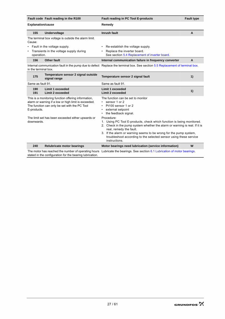
155 Undervoltage Inrush fault A
The terminal box voltage is outside the alarm limit.Cause:• Fault in the voltage supply. • Re-establish the voltage supply.• Transients in the voltage supply during
operation.• Replace the inverter board.
See section 5.4 Replacement of inverter board.
156 Other fault Internal communication failure in frequency converter A
Internal communication fault in the pump due to defect in the terminal box.
Replace the terminal box. See section 5.5 Replacement of terminal box.
175 Temperature sensor 2 signal outside signal range Temperature sensor 2 signal fault 1)
Same as fault 91. Same as fault 91.
190191
Limit 1 exceededLimit 2 exceeded
Limit 1 exceededLimit 2 exceeded 1)
This is a monitoring function offering information, alarm or warning if a low or high limit is exceeded.The function can only be set with the PC Tool E-products.
The function can be set to monitor• sensor 1 or 2• Pt100 sensor 1 or 2• external setpoint• the feedback signal.
The limit set has been exceeded either upwards or downwards.
Procedure:1. Using PC Tool E-products, check which function is being monitored.2. Check in the pump system whether the alarm or warning is real. If it is
real, remedy the fault.3. If the alarm or warning seems to be wrong for the pump system,
troubleshoot according to the selected sensor using these service instructions.
240 Relubricate motor bearings Motor bearings need lubrication (service information) W
The motor has reached the number of operating hours stated in the configuration for the bearing lubrication.
Lubricate the bearings. See section 6.1 Lubrication of motor bearings.
Fault code Fault reading in the R100 Fault reading in PC Tool E-products Fault type
Explanation/cause Remedy
27 / 61
4. Checking the printed-circuit boards
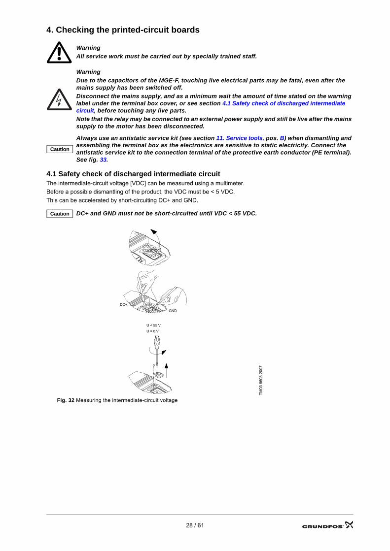
4.1 Safety check of discharged intermediate circuitThe intermediate-circuit voltage [VDC] can be measured using a multimeter.Before a possible dismantling of the product, the VDC must be < 5 VDC. This can be accelerated by short-circuiting DC+ and GND.
WarningAll service work must be carried out by specially trained staff.
WarningDue to the capacitors of the MGE-F, touching live electrical parts may be fatal, even after the mains supply has been switched off.Disconnect the mains supply, and as a minimum wait the amount of time stated on the warning label under the terminal box cover, or see section 4.1 Safety check of discharged intermediate circuit, before touching any live parts.Note that the relay may be connected to an external power supply and still be live after the mains supply to the motor has been disconnected.
Caution
Always use an antistatic service kit (see section 11. Service tools, pos. B) when dismantling and assembling the terminal box as the electronics are sensitive to static electricity. Connect the antistatic service kit to the connection terminal of the protective earth conductor (PE terminal). See fig. 33.
Caution DC+ and GND must not be short-circuited until VDC < 55 VDC.
TM03
860
3 20
07
Fig. 32 Measuring the intermediate-circuit voltage
DC + Test
DC + Test
DC+
U = 0 VU < 55 V
GND
28 / 61
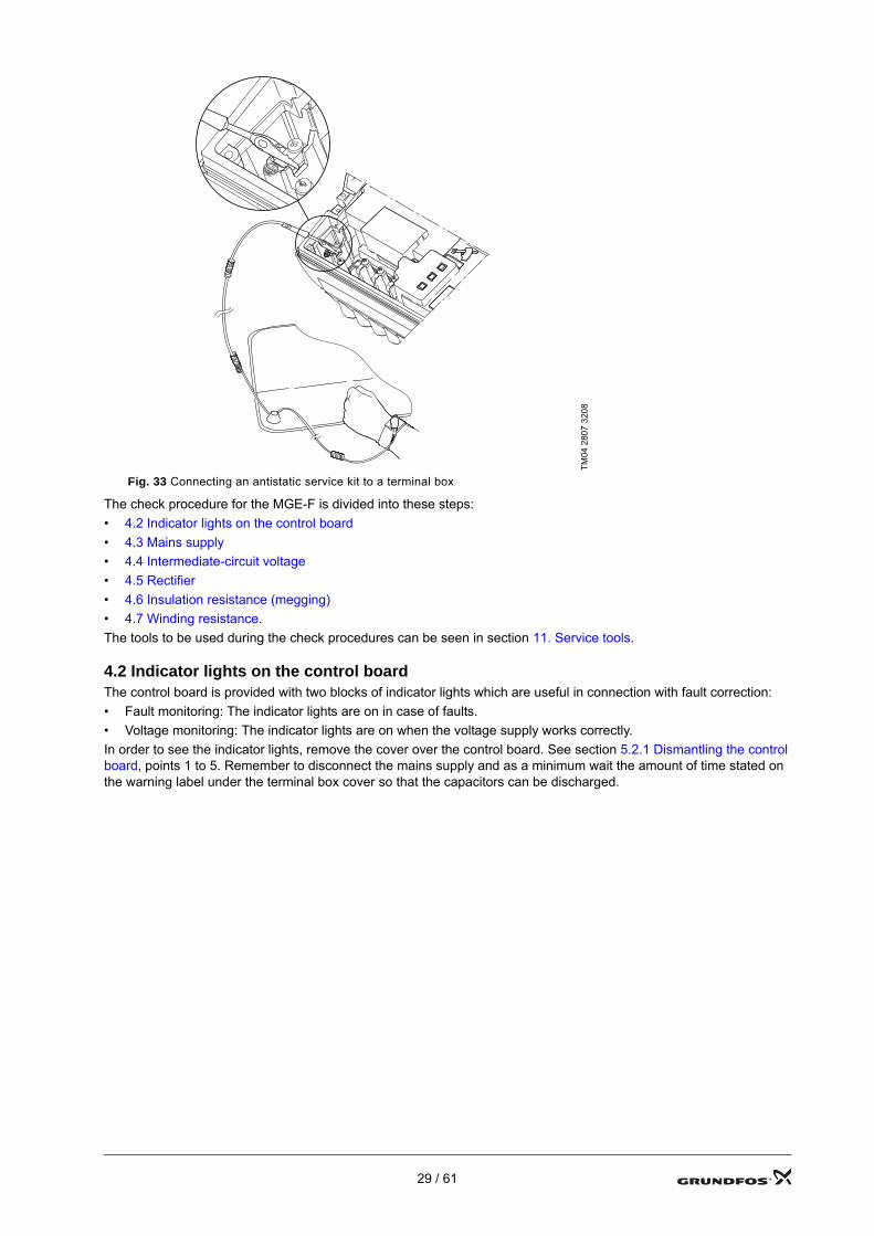
The check procedure for the MGE-F is divided into these steps:• 4.2 Indicator lights on the control board• 4.3 Mains supply• 4.4 Intermediate-circuit voltage• 4.5 Rectifier• 4.6 Insulation resistance (megging)• 4.7 Winding resistance.The tools to be used during the check procedures can be seen in section 11. Service tools.
4.2 Indicator lights on the control boardThe control board is provided with two blocks of indicator lights which are useful in connection with fault correction:• Fault monitoring: The indicator lights are on in case of faults.• Voltage monitoring: The indicator lights are on when the voltage supply works correctly.In order to see the indicator lights, remove the cover over the control board. See section 5.2.1 Dismantling the control board, points 1 to 5. Remember to disconnect the mains supply and as a minimum wait the amount of time stated on the warning label under the terminal box cover so that the capacitors can be discharged.
TM04
280
7 32
08
Fig. 33 Connecting an antistatic service kit to a terminal box
29 / 61
4.2.1 Fault monitoring
TM04
257
0 27
08
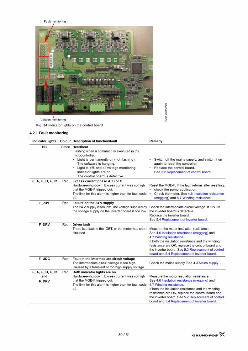
Fig. 34 Indicator lights on the control board
Indicator lights Colour Description of function/fault Remedy
HB Green HeartbeatFlashing when a command is executed in the microcontroller.• Light is permanently on (not flashing):
The software is hanging.• Light is off, and all voltage monitoring
indicator lights are on: The control board is defective.
• Switch off the mains supply, and switch it on again to reset the controller.
• Replace the control board. See 5.2 Replacement of control board.
F_IA, F_IB, F_IC Red Excess current phase A, B or CHardware-shutdown. Excess current was so high that the MGE-F tripped out.The limit for this alarm is higher than for fault code 49.
Reset the MGE-F. If the fault returns after resetting,• check the pump application.• Check the motor. See 4.6 Insulation resistance
(megging) and 4.7 Winding resistance.F_24V Red Failure on the 24 V supply
The 24 V supply is too low. The voltage supplied by the voltage supply on the inverter board is too low.
Check the intermediate-circuit voltage. If it is OK, the inverter board is defective.Replace the inverter board. See 5.4 Replacement of inverter board.
F_DRV Red Driver faultThere is a fault in the IGBT, or the motor has short-circuited.
Measure the motor insulation resistance. See 4.6 Insulation resistance (megging) and 4.7 Winding resistance.If both the insulation resistance and the winding resistance are OK, replace the control board and the inverter board. See 5.2 Replacement of control board and 5.4 Replacement of inverter board.
F_UDC Red Fault in the intermediate-circuit voltageThe intermediate-circuit voltage is too high. Caused by a transient or too high supply voltage.
Check the mains supply. See 4.3 Mains supply.
F_IA, F_IB, F_IC and
F_DRV
Red Both indicator lights are onHardware-shutdown. Excess current was so high that the MGE-F tripped out.The limit for this alarm is higher than for fault code 49.
Measure the motor insulation resistance. See 4.6 Insulation resistance (megging) and 4.7 Winding resistance.If both the insulation resistance and the winding resistance are OK, replace the control board and the inverter board. See 5.2 Replacement of control board and 5.4 Replacement of inverter board.
Fault monitoring
Voltage monitoring
30 / 61
4.2.2 Voltage monitoring
Indicator lights Colour Description of function/fault Remedy
24V Green 24 V supplySupplied from the voltage supply on the inverter board.The indicator light is off.
Check the intermediate-circuit voltage. See 4.4 Intermediate-circuit voltage.• If the intermediate-circuit voltage is missing,
the rectifier board is defective. Replace the rectifier board. See 5.3 Replacement of rectifier board.
• If the intermediate-circuit voltage is OK, the inverter board is defective. Replace the inverter board. See 5.4 Replacement of inverter board.
15V Green 15 V supplyThe voltage comes from the control board.The indicator light is off, and the 24 V light is on. The control board is defective.
Replace the control board. See 5.2 Replacement of control board.
7V Green 7 V supplyThe voltage comes from the control board.The indicator light is off, and the 24 V and the 15 V lights are on. The control board is defective.
Replace the control board. See 5.2 Replacement of control board.
5V Green 5 V supplyThe voltage comes from the control board.The indicator light is off, and the 24 V light is on.The 5 V supply has been cut due to overload.
Switch off the mains supply, remove the functional modules, and switch on the mains supply again.• If the fault has disappeared, one of the
functional modules is defective. Replace one of the functional modules.
• If the fault is not in the functional modules, the control board is defective. Replace the control board. See 5.2 Replacement of control board.
3V5 Green 3.5 V supplyThe voltage comes from the control board.The indicator light is off, and the 24 V and the 5 V lights are on. The control board is defective.
Replace the control board. See 5.2 Replacement of control board.
–6V Green –6 V supplySupplied from the voltage supply on the inverter board.The indicator light is off.
Check the intermediate-circuit voltage. See 4.4 Intermediate-circuit voltage.• If the intermediate-circuit voltage is missing,
the rectifier board is defective. Replace the rectifier board. See 5.3 Replacement of rectifier board.
• If the intermediate-circuit voltage is OK, the inverter board is defective. Replace the inverter board. See 5.4 Replacement of inverter board.
28VS Green 28 V supply on the safe side of the boardSupplied from the voltage supply on the inverter board.The indicator light is off.
Check the intermediate-circuit voltage. See 4.4 Intermediate-circuit voltage.• If the intermediate-circuit voltage is missing,
the rectifier board is defective. Replace the rectifier board. See 5.3 Replacement of rectifier board.
• If the intermediate-circuit voltage is OK, the inverter board is defective. Replace the inverter board. See 5.4 Replacement of inverter board.
5VS Green 5 V supply on the safe side of the boardThe voltage comes from the control board.The indicator light is off, and the 28 V light is on. The control board is defective.
Replace the control board. See 5.2 Replacement of control board.
31 / 61
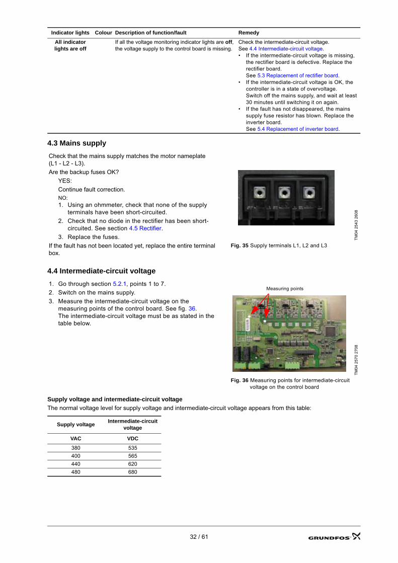
4.3 Mains supply
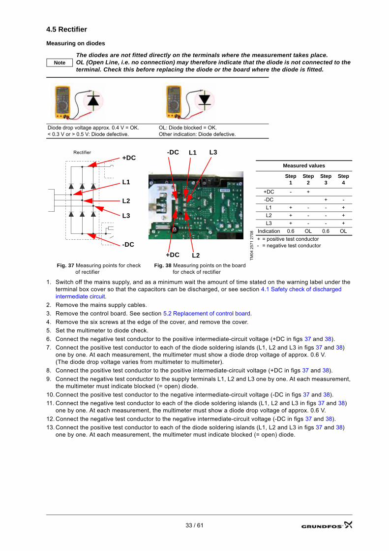
4.4 Intermediate-circuit voltage
Supply voltage and intermediate-circuit voltageThe normal voltage level for supply voltage and intermediate-circuit voltage appears from this table:
All indicator lights are off
If all the voltage monitoring indicator lights are off, the voltage supply to the control board is missing.
Check the intermediate-circuit voltage. See 4.4 Intermediate-circuit voltage.• If the intermediate-circuit voltage is missing,
the rectifier board is defective. Replace the rectifier board. See 5.3 Replacement of rectifier board.
• If the intermediate-circuit voltage is OK, the controller is in a state of overvoltage. Switch off the mains supply, and wait at least 30 minutes until switching it on again.
• If the fault has not disappeared, the mains supply fuse resistor has blown. Replace the inverter board. See 5.4 Replacement of inverter board.
Check that the mains supply matches the motor nameplate (L1 - L2 - L3).
TM04
254
3 26
08
Are the backup fuses OK?YES:Continue fault correction.NO:1. Using an ohmmeter, check that none of the supply
terminals have been short-circuited.2. Check that no diode in the rectifier has been short-
circuited. See section 4.5 Rectifier.3. Replace the fuses.
If the fault has not been located yet, replace the entire terminal box.
Fig. 35 Supply terminals L1, L2 and L3
1. Go through section 5.2.1, points 1 to 7.2. Switch on the mains supply.3. Measure the intermediate-circuit voltage on the
measuring points of the control board. See fig. 36.The intermediate-circuit voltage must be as stated in the table below.
TM04
257
0 27
08
Fig. 36 Measuring points for intermediate-circuit voltage on the control board
Supply voltage Intermediate-circuit voltage
VAC VDC
380 535400 565440 620480 680
Indicator lights Colour Description of function/fault Remedy
Measuring points
32 / 61
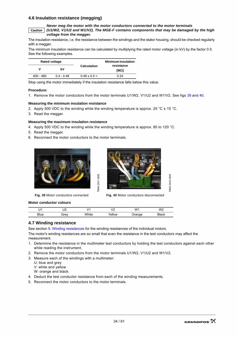
4.5 Rectifier
Measuring on diodes
1. Switch off the mains supply, and as a minimum wait the amount of time stated on the warning label under the terminal box cover so that the capacitors can be discharged, or see section 4.1 Safety check of discharged intermediate circuit.
2. Remove the mains supply cables.3. Remove the control board. See section 5.2 Replacement of control board.4. Remove the six screws at the edge of the cover, and remove the cover.5. Set the multimeter to diode check.6. Connect the negative test conductor to the positive intermediate-circuit voltage (+DC in figs 37 and 38).7. Connect the positive test conductor to each of the diode soldering islands (L1, L2 and L3 in figs 37 and 38)
one by one. At each measurement, the multimeter must show a diode drop voltage of approx. 0.6 V. (The diode drop voltage varies from multimeter to multimeter).
8. Connect the positive test conductor to the positive intermediate-circuit voltage (+DC in figs 37 and 38).9. Connect the negative test conductor to the supply terminals L1, L2 and L3 one by one. At each measurement,
the multimeter must indicate blocked (= open) diode.10. Connect the positive test conductor to the negative intermediate-circuit voltage (-DC in figs 37 and 38).11. Connect the negative test conductor to each of the diode soldering islands (L1, L2 and L3 in figs 37 and 38)
one by one. At each measurement, the multimeter must show a diode drop voltage of approx. 0.6 V.12. Connect the negative test conductor to the negative intermediate-circuit voltage (-DC in figs 37 and 38).13. Connect the positive test conductor to each of the diode soldering islands (L1, L2 and L3 in figs 37 and 38)
one by one. At each measurement, the multimeter must indicate blocked (= open) diode.
NoteThe diodes are not fitted directly on the terminals where the measurement takes place. OL (Open Line, i.e. no connection) may therefore indicate that the diode is not connected to the terminal. Check this before replacing the diode or the board where the diode is fitted.
Diode drop voltage approx. 0.4 V = OK.< 0.3 V or > 0.5 V: Diode defective.
OL: Diode blocked = OK.Other indication: Diode defective.
TM04
257
1 27
08
Measured values
Step 1
Step 2
Step 3
Step 4
+DC - +-DC + -L1 + - - +L2 + - - +L3 + - - +
Indication 0.6 OL 0.6 OL+ = positive test conductor- = negative test conductor
Fig. 37 Measuring points for check of rectifier
Fig. 38 Measuring points on the board for check of rectifier
Rectifier
-DC
+DC
L1
L2
L3
+DC
-DC L1 L3
L2
33 / 61
4.6 Insulation resistance (megging)
The insulation resistance, i.e. the resistance between the windings and the stator housing, should be checked regularly with a megger.The minimum insulation resistance can be calculated by multiplying the rated motor voltage (in kV) by the factor 0.5. See the following examples.
Stop using the motor immediately if the insulation resistance falls below this value.
Procedure:1. Remove the motor conductors from the motor terminals U1/W2, V1/U2 and W1/V2. See figs 39 and 40.
Measuring the minimum insulation resistance2. Apply 500 VDC to the winding while the winding temperature is approx. 25 °C ± 15 °C.3. Read the megger.
Measuring the maximum insulation resistance4. Apply 500 VDC to the winding while the winding temperature is approx. 80 to 120 °C.5. Read the megger.6. Reconnect the motor conductors to the motor terminals.
Motor conductor colours
4.7 Winding resistanceSee section 9. Winding resistances for the winding resistances of the individual motors.The motor's winding resistances are so small that even the resistance in the test conductors may affect the measurement.1. Determine the resistance in the multimeter test conductors by holding the test conductors against each other
while reading the instrument.2. Remove the motor conductors from the motor terminals U1/W2, V1/U2 and W1/V2.3. Measure each of the windings with a multimeter:
U: blue and greyV: white and yellowW: orange and black.
4. Deduct the test conductor resistance from each of the winding measurements.5. Reconnect the motor conductors to the motor terminals.
CautionNever meg the motor with the motor conductors connected to the motor terminals (U1/W2, V1/U2 and W1/V2). The MGE-F contains components that may be damaged by the high voltage from the megger.
Rated voltageCalculation
Minimum insulation resistance
[MΩ]V kV
400 - 480 0.4 - 0.48 0.48 x 0.5 = 0.24
TM04
254
1 26
08
TM04
254
2 26
08
Fig. 39 Motor conductors connected Fig. 40 Motor conductors disconnected
U1 U2 V1 V2 W1 W2Blue Grey White Yellow Orange Black
34 / 61
5. Replacement of modules
Replacement of the modules in the terminal box covers various procedures that are all described in the following sections.Follow these instructions if it is necessary to dismantle the motor or the terminal box to replace components.Position numbers of components (numbers in brackets) refer to section 8. Drawings and diagrams. Position letters of tools (letters in brackets) refer to section 11. Service tools.
Prior to dismantlingDisconnect the mains supply in accordance with local regulations.
During assemblyTighten screws and nuts to the correct torque. See section 10.1 Tightening torques.
WarningAll service work must be carried out by specially trained staff.
WarningDue to the capacitors of the MGE-F, touching live electrical parts may be fatal, even after the mains supply has been switched off.Disconnect the mains supply, and as a minimum wait the amount of time stated on the warning label under the terminal box cover, or see section 4.1 Safety check of discharged intermediate circuit, before touching any live parts.Note that the relay may be connected to an external power supply and still be live after the mains supply to the motor has been disconnected.
WarningThe MGE-F may be hot!
Caution
Always use an antistatic service kit (see section 11. Service tools, pos. B) when dismantling and assembling the terminal box as the electronics are sensitive to static electricity. Connect the antistatic service kit to the connection terminal of the protective earth conductor (PE terminal). See fig. 33.
35 / 61
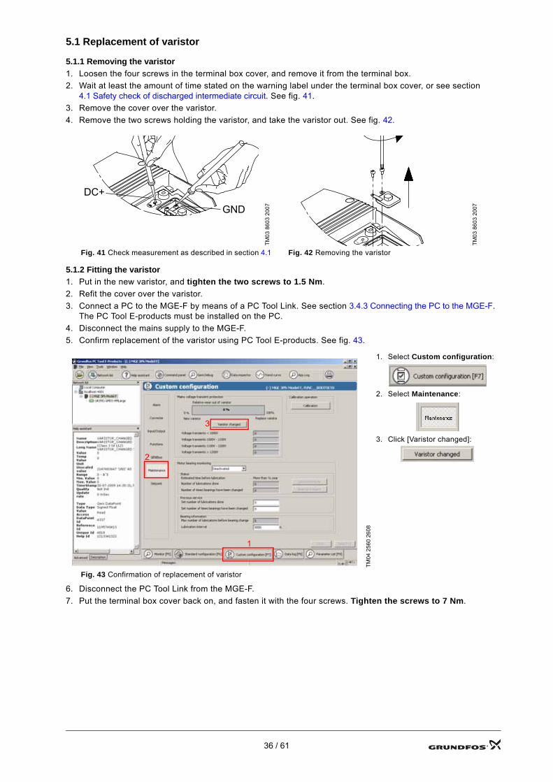
5.1 Replacement of varistor
5.1.1 Removing the varistor1. Loosen the four screws in the terminal box cover, and remove it from the terminal box.2. Wait at least the amount of time stated on the warning label under the terminal box cover, or see section
4.1 Safety check of discharged intermediate circuit. See fig. 41.3. Remove the cover over the varistor.4. Remove the two screws holding the varistor, and take the varistor out. See fig. 42.
5.1.2 Fitting the varistor1. Put in the new varistor, and tighten the two screws to 1.5 Nm.2. Refit the cover over the varistor.3. Connect a PC to the MGE-F by means of a PC Tool Link. See section 3.4.3 Connecting the PC to the MGE-F.
The PC Tool E-products must be installed on the PC.4. Disconnect the mains supply to the MGE-F.5. Confirm replacement of the varistor using PC Tool E-products. See fig. 43.
6. Disconnect the PC Tool Link from the MGE-F.7. Put the terminal box cover back on, and fasten it with the four screws. Tighten the screws to 7 Nm.
TM03
860
3 20
07
TM03
860
3 20
07
Fig. 41 Check measurement as described in section 4.1 Fig. 42 Removing the varistor
TM04
256
0 26
08
1. Select Custom configuration:
2. Select Maintenance:
3. Click [Varistor changed]:
Fig. 43 Confirmation of replacement of varistor
DC+
GND
DC + Test
DC + Test
1
2
3
36 / 61
5.2 Replacement of control board
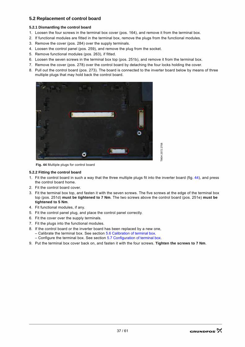
5.2.1 Dismantling the control board1. Loosen the four screws in the terminal box cover (pos. 164), and remove it from the terminal box.2. If functional modules are fitted in the terminal box, remove the plugs from the functional modules.3. Remove the cover (pos. 284) over the supply terminals.4. Loosen the control panel (pos. 259), and remove the plug from the socket.5. Remove functional modules (pos. 263), if fitted.6. Loosen the seven screws in the terminal box top (pos. 251b), and remove it from the terminal box.7. Remove the cover (pos. 278) over the control board by detaching the four locks holding the cover.8. Pull out the control board (pos. 273). The board is connected to the inverter board below by means of three
multiple plugs that may hold back the control board.
5.2.2 Fitting the control board1. Fit the control board in such a way that the three multiple plugs fit into the inverter board (fig. 44), and press
the control board home.2. Fit the control board cover.3. Fit the terminal box top, and fasten it with the seven screws. The five screws at the edge of the terminal box
top (pos. 251d) must be tightened to 7 Nm. The two screws above the control board (pos. 251e) must be tightened to 5 Nm.
4. Fit functional modules, if any.5. Fit the control panel plug, and place the control panel correctly.6. Fit the cover over the supply terminals.7. Fit the plugs into the functional modules.8. If the control board or the inverter board has been replaced by a new one,
– Calibrate the terminal box. See section 5.6 Calibration of terminal box.– Configure the terminal box. See section 5.7 Configuration of terminal box.
9. Put the terminal box cover back on, and fasten it with the four screws. Tighten the screws to 7 Nm.
TM04
257
2 27
08Fig. 44 Multiple plugs for control board
37 / 61
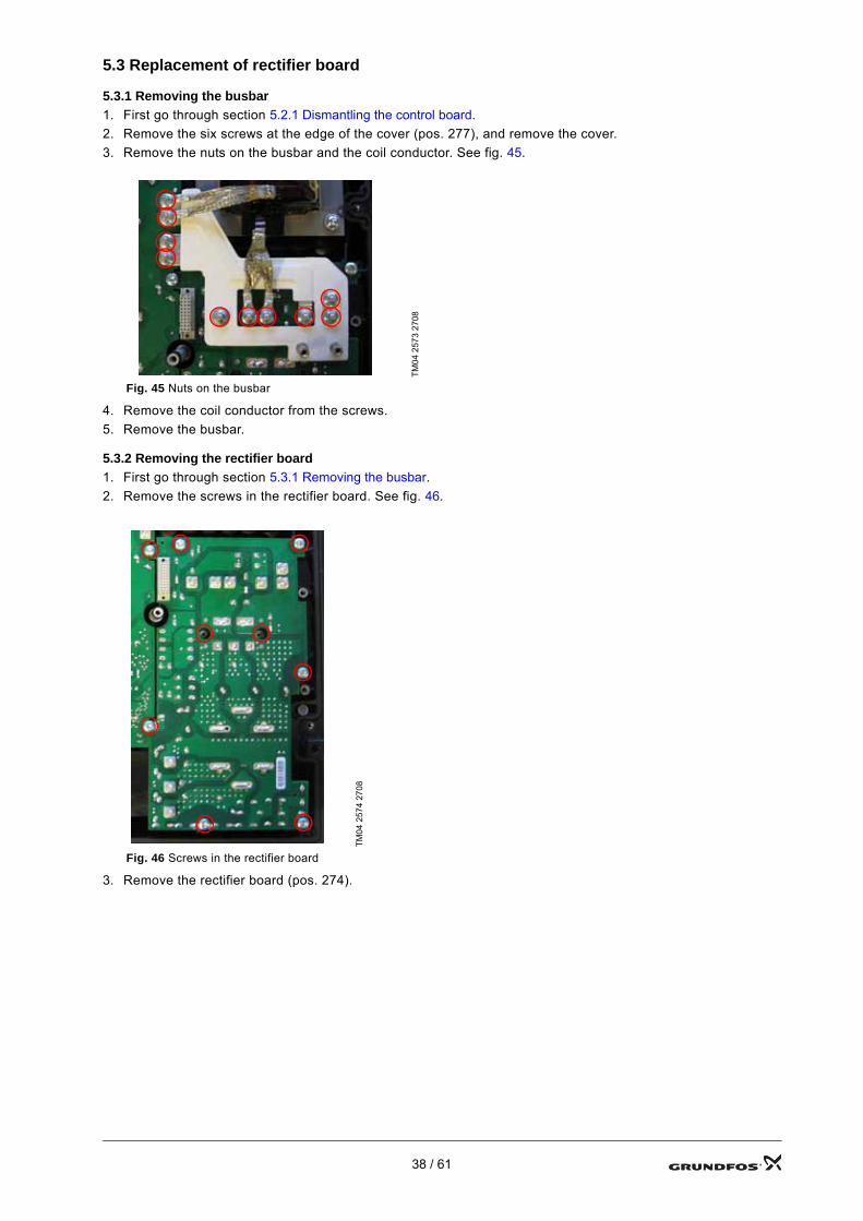
5.3 Replacement of rectifier board
5.3.1 Removing the busbar1. First go through section 5.2.1 Dismantling the control board.2. Remove the six screws at the edge of the cover (pos. 277), and remove the cover.3. Remove the nuts on the busbar and the coil conductor. See fig. 45.
4. Remove the coil conductor from the screws.5. Remove the busbar.
5.3.2 Removing the rectifier board1. First go through section 5.3.1 Removing the busbar.2. Remove the screws in the rectifier board. See fig. 46.
3. Remove the rectifier board (pos. 274).
TM04
257
3 27
08
Fig. 45 Nuts on the busbar
TM04
257
4 27
08
Fig. 46 Screws in the rectifier board
38 / 61
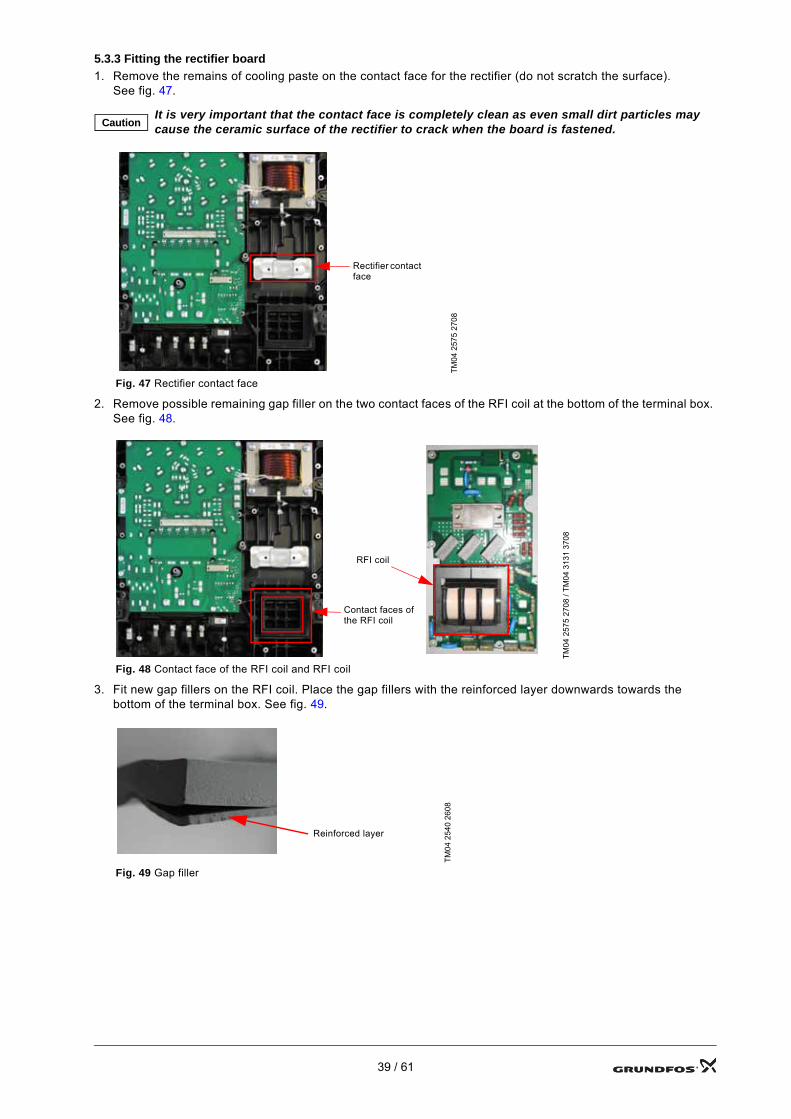
5.3.3 Fitting the rectifier board1. Remove the remains of cooling paste on the contact face for the rectifier (do not scratch the surface).
See fig. 47.
2. Remove possible remaining gap filler on the two contact faces of the RFI coil at the bottom of the terminal box. See fig. 48.
3. Fit new gap fillers on the RFI coil. Place the gap fillers with the reinforced layer downwards towards the bottom of the terminal box. See fig. 49.
CautionIt is very important that the contact face is completely clean as even small dirt particles may cause the ceramic surface of the rectifier to crack when the board is fastened.
TM04
257
5 27
08
Fig. 47 Rectifier contact face
TM04
257
5 27
08 /
TM04
313
1 37
08
Fig. 48 Contact face of the RFI coil and RFI coil
TM04
254
0 26
08
Fig. 49 Gap filler
Rectifier contact face
Contact faces of the RFI coil
RFI coil
Reinforced layer
39 / 61
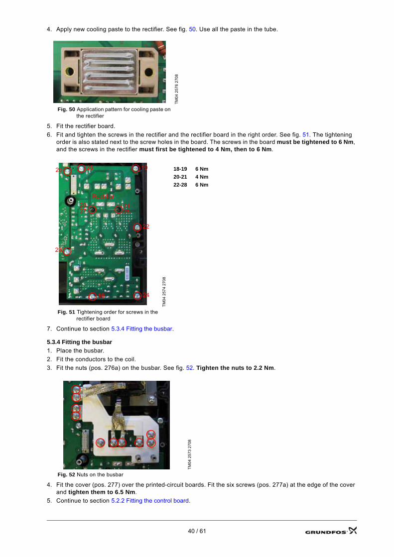
4. Apply new cooling paste to the rectifier. See fig. 50. Use all the paste in the tube.
5. Fit the rectifier board.6. Fit and tighten the screws in the rectifier and the rectifier board in the right order. See fig. 51. The tightening
order is also stated next to the screw holes in the board. The screws in the board must be tightened to 6 Nm, and the screws in the rectifier must first be tightened to 4 Nm, then to 6 Nm.
7. Continue to section 5.3.4 Fitting the busbar.
5.3.4 Fitting the busbar1. Place the busbar.2. Fit the conductors to the coil.3. Fit the nuts (pos. 276a) on the busbar. See fig. 52. Tighten the nuts to 2.2 Nm.
4. Fit the cover (pos. 277) over the printed-circuit boards. Fit the six screws (pos. 277a) at the edge of the cover and tighten them to 6.5 Nm.
5. Continue to section 5.2.2 Fitting the control board.
TM04
257
6 27
08
Fig. 50 Application pattern for cooling paste on the rectifier
TM04
257
4 27
0818-19 6 Nm20-21 4 Nm22-28 6 Nm
Fig. 51 Tightening order for screws in the rectifier board
TM04
257
3 27
08
Fig. 52 Nuts on the busbar
Rectifier2027
18
19
22
24
2526
23
2128
40 / 61
5.4 Replacement of inverter board
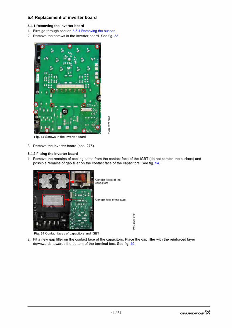
5.4.1 Removing the inverter board1. First go through section 5.3.1 Removing the busbar.2. Remove the screws in the inverter board. See fig. 53.
3. Remove the inverter board (pos. 275).
5.4.2 Fitting the inverter board1. Remove the remains of cooling paste from the contact face of the IGBT (do not scratch the surface) and
possible remains of gap filler on the contact face of the capacitors. See fig. 54.
2. Fit a new gap filler on the contact face of the capacitors. Place the gap filler with the reinforced layer downwards towards the bottom of the terminal box. See fig. 49.
TM04
257
7 27
08
Fig. 53 Screws in the inverter boardTM
04 2
578
2708
Fig. 54 Contact faces of capacitors and IGBT
Contact face of the IGBT
Contact faces of the capacitors
41 / 61
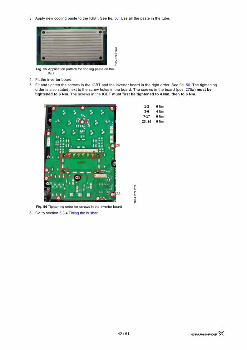
3. Apply new cooling paste to the IGBT. See fig. 50. Use all the paste in the tube.
4. Fit the inverter board.5. Fit and tighten the screws in the IGBT and the inverter board in the right order. See fig. 56. The tightening
order is also stated next to the screw holes in the board. The screws in the board (pos. 275a) must be tightened to 6 Nm. The screws in the IGBT must first be tightened to 4 Nm, then to 6 Nm.
6. Go to section 5.3.4 Fitting the busbar.
TM04
257
9 27
08
Fig. 55 Application pattern for cooling paste on the IGBT
TM04
257
7 27
08
1-2 6 Nm3-6 4 Nm
7-17 6 Nm23, 26 6 Nm
Fig. 56 Tightening order for screws in the inverter board
2
1
7
89
10
11
12
1323
26
314
516
617
415
IGBT
42 / 61
5.5 Replacement of terminal box
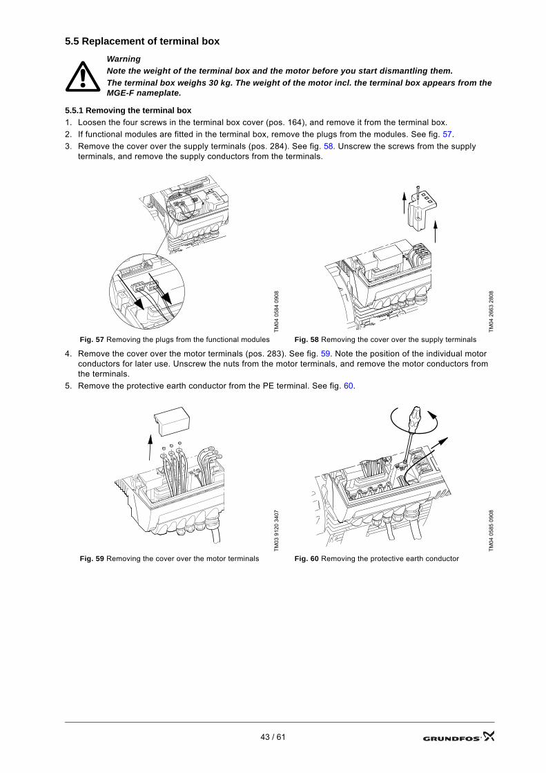
5.5.1 Removing the terminal box1. Loosen the four screws in the terminal box cover (pos. 164), and remove it from the terminal box.2. If functional modules are fitted in the terminal box, remove the plugs from the modules. See fig. 57.3. Remove the cover over the supply terminals (pos. 284). See fig. 58. Unscrew the screws from the supply
terminals, and remove the supply conductors from the terminals.
4. Remove the cover over the motor terminals (pos. 283). See fig. 59. Note the position of the individual motor conductors for later use. Unscrew the nuts from the motor terminals, and remove the motor conductors from the terminals.
5. Remove the protective earth conductor from the PE terminal. See fig. 60.
WarningNote the weight of the terminal box and the motor before you start dismantling them.The terminal box weighs 30 kg. The weight of the motor incl. the terminal box appears from the MGE-F nameplate.
TM04
058
4 09
08
TM04
266
3 28
08
Fig. 57 Removing the plugs from the functional modules Fig. 58 Removing the cover over the supply terminals
TM03
912
0 34
07
TM04
058
5 09
08
Fig. 59 Removing the cover over the motor terminals Fig. 60 Removing the protective earth conductor
43 / 61
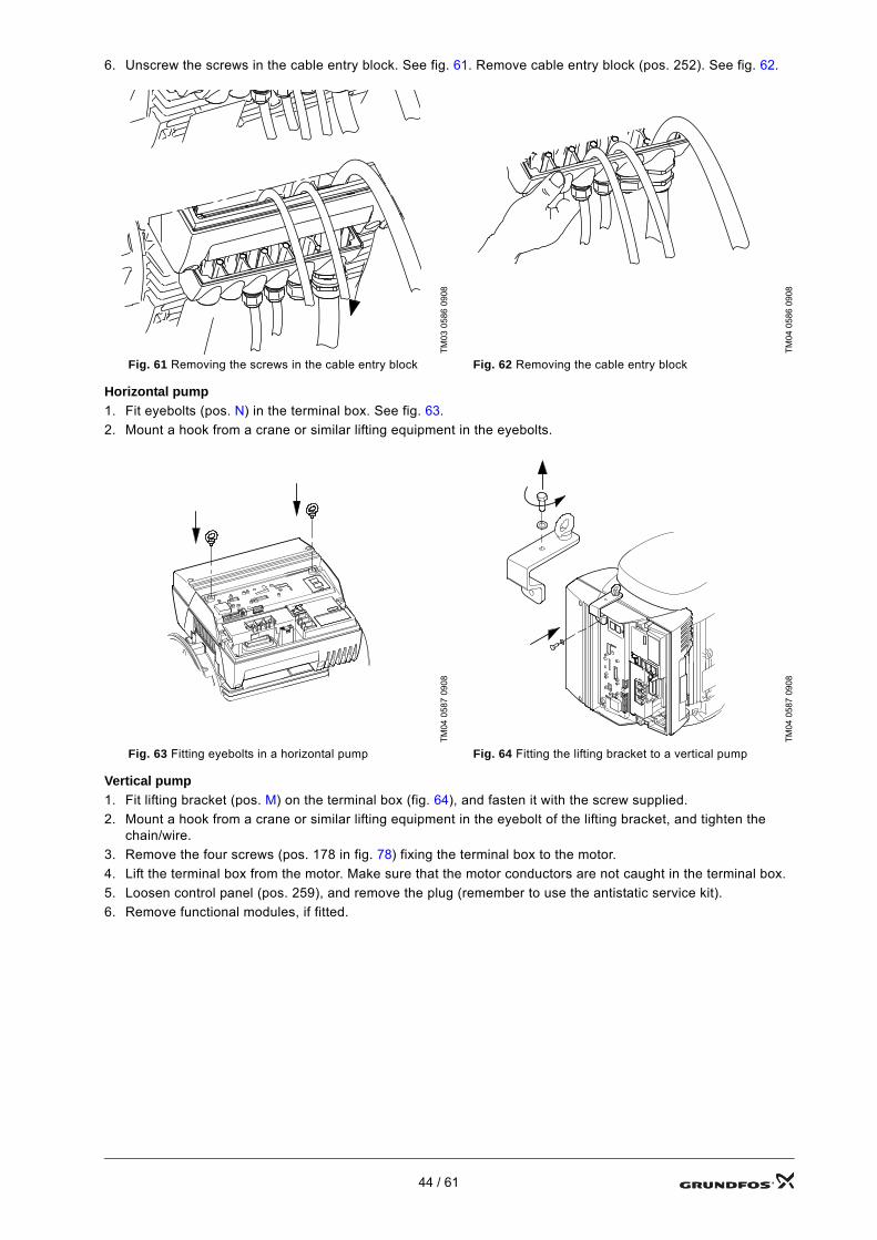
6. Unscrew the screws in the cable entry block. See fig. 61. Remove cable entry block (pos. 252). See fig. 62.
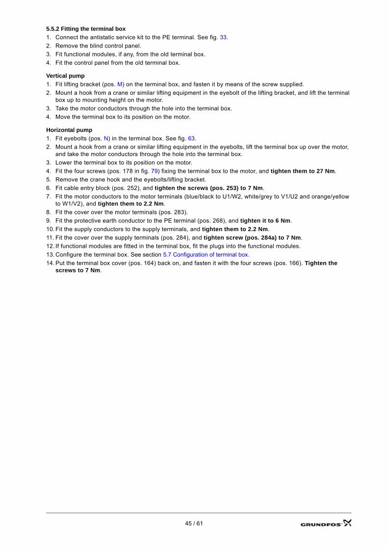
Horizontal pump1. Fit eyebolts (pos. N) in the terminal box. See fig. 63.2. Mount a hook from a crane or similar lifting equipment in the eyebolts.
Vertical pump1. Fit lifting bracket (pos. M) on the terminal box (fig. 64), and fasten it with the screw supplied.2. Mount a hook from a crane or similar lifting equipment in the eyebolt of the lifting bracket, and tighten the
chain/wire.3. Remove the four screws (pos. 178 in fig. 78) fixing the terminal box to the motor.4. Lift the terminal box from the motor. Make sure that the motor conductors are not caught in the terminal box.5. Loosen control panel (pos. 259), and remove the plug (remember to use the antistatic service kit).6. Remove functional modules, if fitted.
TM03
058
6 09
08
TM04
058
6 09
08
Fig. 61 Removing the screws in the cable entry block Fig. 62 Removing the cable entry block
TM04
058
7 09
08
TM04
058
7 09
08
Fig. 63 Fitting eyebolts in a horizontal pump Fig. 64 Fitting the lifting bracket to a vertical pump
44 / 61
5.5.2 Fitting the terminal box1. Connect the antistatic service kit to the PE terminal. See fig. 33.2. Remove the blind control panel.3. Fit functional modules, if any, from the old terminal box.4. Fit the control panel from the old terminal box.
Vertical pump1. Fit lifting bracket (pos. M) on the terminal box, and fasten it by means of the screw supplied.2. Mount a hook from a crane or similar lifting equipment in the eyebolt of the lifting bracket, and lift the terminal
box up to mounting height on the motor.3. Take the motor conductors through the hole into the terminal box.4. Move the terminal box to its position on the motor.
Horizontal pump1. Fit eyebolts (pos. N) in the terminal box. See fig. 63.2. Mount a hook from a crane or similar lifting equipment in the eyebolts, lift the terminal box up over the motor,
and take the motor conductors through the hole into the terminal box.3. Lower the terminal box to its position on the motor.4. Fit the four screws (pos. 178 in fig. 79) fixing the terminal box to the motor, and tighten them to 27 Nm.5. Remove the crane hook and the eyebolts/lifting bracket.6. Fit cable entry block (pos. 252), and tighten the screws (pos. 253) to 7 Nm.7. Fit the motor conductors to the motor terminals (blue/black to U1/W2, white/grey to V1/U2 and orange/yellow
to W1/V2), and tighten them to 2.2 Nm.8. Fit the cover over the motor terminals (pos. 283).9. Fit the protective earth conductor to the PE terminal (pos. 268), and tighten it to 6 Nm.10. Fit the supply conductors to the supply terminals, and tighten them to 2.2 Nm.11. Fit the cover over the supply terminals (pos. 284), and tighten screw (pos. 284a) to 7 Nm.12. If functional modules are fitted in the terminal box, fit the plugs into the functional modules.13. Configure the terminal box. See section 5.7 Configuration of terminal box.14. Put the terminal box cover (pos. 164) back on, and fasten it with the four screws (pos. 166). Tighten the
screws to 7 Nm.
45 / 61
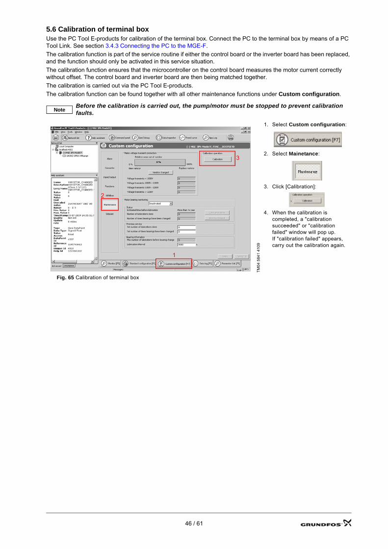
5.6 Calibration of terminal boxUse the PC Tool E-products for calibration of the terminal box. Connect the PC to the terminal box by means of a PC Tool Link. See section 3.4.3 Connecting the PC to the MGE-F.The calibration function is part of the service routine if either the control board or the inverter board has been replaced, and the function should only be activated in this service situation.The calibration function ensures that the microcontroller on the control board measures the motor current correctly without offset. The control board and inverter board are then being matched together.The calibration is carried out via the PC Tool E-products.The calibration function can be found together with all other maintenance functions under Custom configuration.
NoteBefore the calibration is carried out, the pump/motor must be stopped to prevent calibration faults.
TM04
584
1 41
09
1. Select Custom configuration:
2. Select Mainetance:
3. Click [Calibration]:
4. When the calibration is completed, a "calibration succeeded" or "calibration failed" window will pop up. If "calibration failed" appears, carry out the calibration again.
Fig. 65 Calibration of terminal box
1
2
3
46 / 61
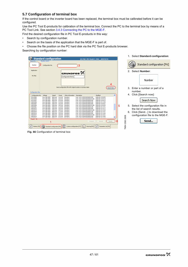
5.7 Configuration of terminal boxIf the control board or the inverter board has been replaced, the terminal box must be calibrated before it can be configured.Use the PC Tool E-products for calibration of the terminal box. Connect the PC to the terminal box by means of a PC Tool Link. See section 3.4.3 Connecting the PC to the MGE-F.Find the desired configuration file in PC Tool E-products in this way:• Search by configuration number.• Search on the basis of the application that the MGE-F is part of.• Choose the file position on the PC hard disk via the PC Tool E-products browser.Searching by configuration number:
TM04
256
3 26
08
1. Select Standard configuration:
2. Select Number:
3. Enter a number or part of a number.
4. Click [Search now]:
5. Select the configuration file in the list of search results.
6. Click [Send...] to download the configuration file to the MGE-F.
Fig. 66 Configuration of terminal box
4
1
2 3
5
6
47 / 61
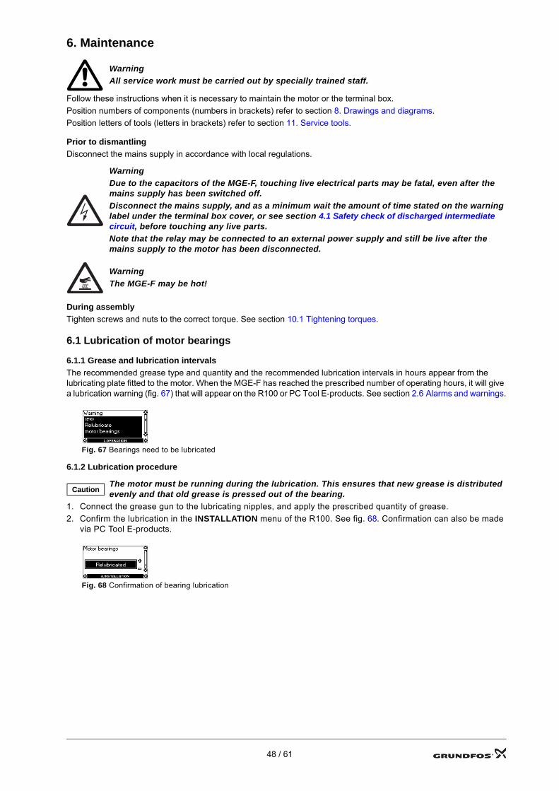
6. Maintenance
Follow these instructions when it is necessary to maintain the motor or the terminal box.Position numbers of components (numbers in brackets) refer to section 8. Drawings and diagrams. Position letters of tools (letters in brackets) refer to section 11. Service tools.
Prior to dismantlingDisconnect the mains supply in accordance with local regulations.
During assemblyTighten screws and nuts to the correct torque. See section 10.1 Tightening torques.
6.1 Lubrication of motor bearings
6.1.1 Grease and lubrication intervalsThe recommended grease type and quantity and the recommended lubrication intervals in hours appear from the lubricating plate fitted to the motor. When the MGE-F has reached the prescribed number of operating hours, it will give a lubrication warning (fig. 67) that will appear on the R100 or PC Tool E-products. See section 2.6 Alarms and warnings.
6.1.2 Lubrication procedure
1. Connect the grease gun to the lubricating nipples, and apply the prescribed quantity of grease.2. Confirm the lubrication in the INSTALLATION menu of the R100. See fig. 68. Confirmation can also be made
via PC Tool E-products.
WarningAll service work must be carried out by specially trained staff.
WarningDue to the capacitors of the MGE-F, touching live electrical parts may be fatal, even after the mains supply has been switched off.Disconnect the mains supply, and as a minimum wait the amount of time stated on the warning label under the terminal box cover, or see section 4.1 Safety check of discharged intermediate circuit, before touching any live parts.Note that the relay may be connected to an external power supply and still be live after the mains supply to the motor has been disconnected.
WarningThe MGE-F may be hot!
Fig. 67 Bearings need to be lubricated
CautionThe motor must be running during the lubrication. This ensures that new grease is distributed evenly and that old grease is pressed out of the bearing.
Fig. 68 Confirmation of bearing lubrication
48 / 61
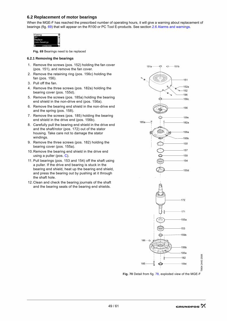
6.2 Replacement of motor bearingsWhen the MGE-F has reached the prescribed number of operating hours, it will give a warning about replacement of bearings (fig. 69) that will appear on the R100 or PC Tool E-products. See section 2.6 Alarms and warnings.
6.2.1 Removing the bearings
Fig. 69 Bearings need to be replaced
1. Remove the screws (pos. 152) holding the fan cover (pos. 151), and remove the fan cover.
2. Remove the retaining ring (pos. 156c) holding the fan (pos. 156).
3. Pull off the fan.4. Remove the three screws (pos. 182a) holding the
bearing cover (pos. 155d).5. Remove the screws (pos. 185a) holding the bearing
end shield in the non-drive end (pos. 156a).6. Remove the bearing end shield in the non-drive end
and the spring (pos. 158).7. Remove the screws (pos. 185) holding the bearing
end shield in the drive end (pos. 156b).8. Carefully pull the bearing end shield in the drive end
and the shaft/rotor (pos. 172) out of the stator housing. Take care not to damage the stator windings.
9. Remove the three screws (pos. 182) holding the bearing cover (pos. 155a).
10. Remove the bearing end shield in the drive end using a puller (pos. C).
11. Pull bearings (pos. 153 and 154) off the shaft using a puller. If the drive end bearing is stuck in the bearing end shield, heat up the bearing end shield, and press the bearing out by pushing at it through the shaft hole.
12. Clean and check the bearing journals of the shaft and the bearing seats of the bearing end shields.
TM04
244
3 25
08
Fig. 70 Detail from fig. 78, exploded view of the MGE-F
49 / 61
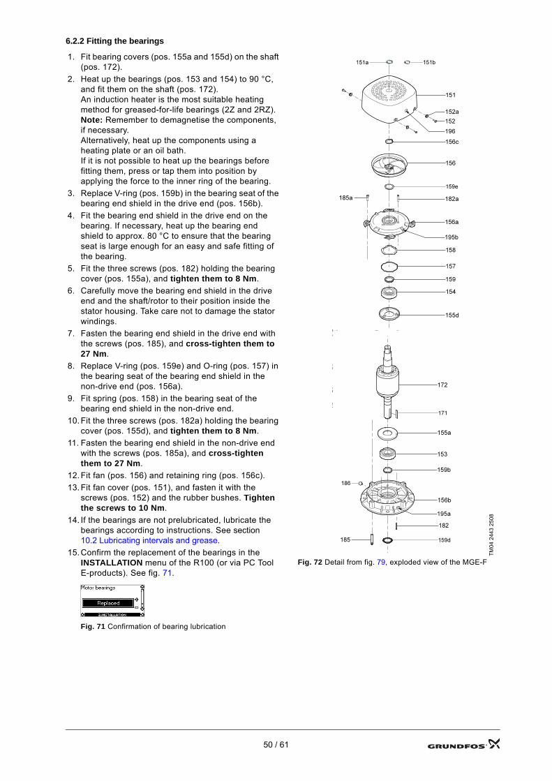
6.2.2 Fitting the bearings
1. Fit bearing covers (pos. 155a and 155d) on the shaft (pos. 172).
2. Heat up the bearings (pos. 153 and 154) to 90 °C, and fit them on the shaft (pos. 172).An induction heater is the most suitable heating method for greased-for-life bearings (2Z and 2RZ).Note: Remember to demagnetise the components, if necessary.Alternatively, heat up the components using a heating plate or an oil bath.If it is not possible to heat up the bearings before fitting them, press or tap them into position by applying the force to the inner ring of the bearing.
3. Replace V-ring (pos. 159b) in the bearing seat of the bearing end shield in the drive end (pos. 156b).
4. Fit the bearing end shield in the drive end on the bearing. If necessary, heat up the bearing end shield to approx. 80 °C to ensure that the bearing seat is large enough for an easy and safe fitting of the bearing.
5. Fit the three screws (pos. 182) holding the bearing cover (pos. 155a), and tighten them to 8 Nm.
6. Carefully move the bearing end shield in the drive end and the shaft/rotor to their position inside the stator housing. Take care not to damage the stator windings.
7. Fasten the bearing end shield in the drive end with the screws (pos. 185), and cross-tighten them to 27 Nm.
8. Replace V-ring (pos. 159e) and O-ring (pos. 157) in the bearing seat of the bearing end shield in the non-drive end (pos. 156a).
9. Fit spring (pos. 158) in the bearing seat of the bearing end shield in the non-drive end.
10. Fit the three screws (pos. 182a) holding the bearing cover (pos. 155d), and tighten them to 8 Nm.
11. Fasten the bearing end shield in the non-drive end with the screws (pos. 185a), and cross-tighten them to 27 Nm.
12. Fit fan (pos. 156) and retaining ring (pos. 156c).13. Fit fan cover (pos. 151), and fasten it with the
screws (pos. 152) and the rubber bushes. Tighten the screws to 10 Nm.
14. If the bearings are not prelubricated, lubricate the bearings according to instructions. See section 10.2 Lubricating intervals and grease.
15. Confirm the replacement of the bearings in the INSTALLATION menu of the R100 (or via PC Tool E-products). See fig. 71.
Fig. 71 Confirmation of bearing lubrication
TM04
244
3 25
08
Fig. 72 Detail from fig. 79, exploded view of the MGE-F
50 / 61
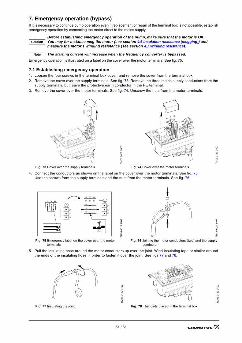
7. Emergency operation (bypass)If it is necessary to continue pump operation even if replacement or repair of the terminal box is not possible, establish emergency operation by connecting the motor direct to the mains supply.
Emergency operation is illustrated on a label on the cover over the motor terminals. See fig. 75.
7.1 Establishing emergency operation1. Loosen the four screws in the terminal box cover, and remove the cover from the terminal box.2. Remove the cover over the supply terminals. See fig. 73. Remove the three mains supply conductors from the
supply terminals, but leave the protective earth conductor in the PE terminal.3. Remove the cover over the motor terminals. See fig. 74. Unscrew the nuts from the motor terminals.
4. Connect the conductors as shown on the label on the cover over the motor terminals. See fig. 75.Use the screws from the supply terminals and the nuts from the motor terminals. See fig. 76.
5. Pull the insulating hose around the motor conductors up over the joint. Wind insulating tape or similar around the ends of the insulating hose in order to fasten it over the joint. See figs 77 and 78.
CautionBefore establishing emergency operation of the pump, make sure that the motor is OK. You may for instance meg the motor (see section 4.6 Insulation resistance (megging)) and measure the motor's winding resistance (see section 4.7 Winding resistance).
Note The starting current will increase when the frequency converter is bypassed.
TM03
860
7 20
07
TM03
912
0 34
07
Fig. 73 Cover over the supply terminals Fig. 74 Cover over the motor terminals
TM04
001
8 48
07
TM03
912
1 34
07
Fig. 75 Emergency label on the cover over the motor terminals
Fig. 76 Joining the motor conductors (two) and the supply conductor
TM03
912
2 34
07
TM03
912
3 34
07
Fig. 77 Insulating the joint Fig. 78 The joints placed in the terminal box
51 / 61
6. Briefly start the motor, and observe the direction of rotation.
7. If the motor's direction of rotation is wrong, interchange two of the supply conductors (phases).8. Put the terminal box cover (pos. 164) back on, and fasten it with the four screws (pos. 166).
Tighten the screws to 7 Nm.
7.2 Re-establishment of frequency converter operation1. Loosen the four screws in the terminal box cover, and remove the cover from the terminal box.2. Remove the insulating tape, and separate one of the joints of motor conductors and supply conductor.
Push the insulating hose down over the motor conductors again.3. Fit the motor conductors on the correct motor terminal: Blue/black to U1/W2, white/grey to V1/U2 and orange/
yellow to W1/V2. Tighten them to 2.2 Nm.4. Fit the supply conductor to one of the supply terminals, and tighten it to 2.2 Nm.5. Repeat steps 2 to 4 for the remaining two joints.6. Fit the cover over the motor terminals.7. Fit the cover over the supply terminals (pos. 284), and tighten the screw to 7 Nm.8. Put the terminal box cover (pos. 164) back on, and fasten it with the four screws (pos. 166).
Tighten the screws to 7 Nm.
NoteIt is important to check (and change, if necessary) the motor's direction of rotation in order to ensure that the pump is not running backwards.
52 / 61
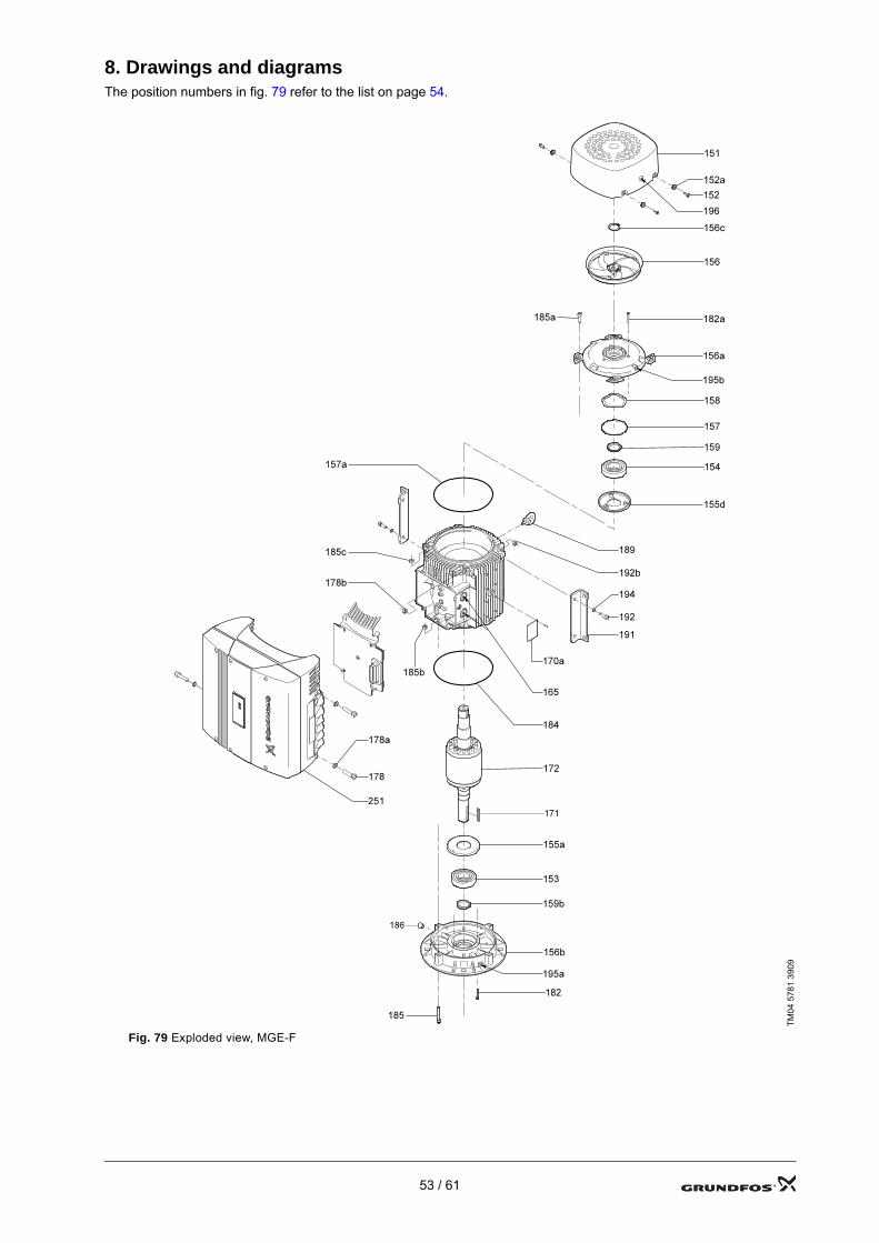
8. Drawings and diagramsThe position numbers in fig. 79 refer to the list on page 54.
TM04
578
1 39
09
Fig. 79 Exploded view, MGE-F
53 / 61
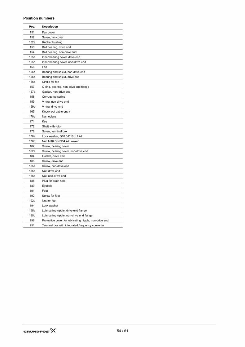
Position numbers
Pos. Description
151 Fan cover
152 Screw, fan cover
152a Rubber bushing
153 Ball bearing, drive end
154 Ball bearing, non-drive end
155a Inner bearing cover, drive end
155d Inner bearing cover, non-drive end
156 Fan
156a Bearing end shield, non-drive end
156b Bearing end shield, drive end
156c Circlip for fan
157 O-ring, bearing, non-drive end flange
157a Gasket, non-drive end
158 Corrugated spring
159 V-ring, non-drive end
159b V-ring, drive end
165 Knock-out cable entry
170a Nameplate
171 Key
172 Shaft with rotor
178 Screw, terminal box
178a Lock washer, D10.5/D16 x 1 A2
178b Nut, M10 DIN 934 A2, waxed
182 Screw, bearing cover
182a Screw, bearing cover, non-drive end
184 Gasket, drive end
185 Screw, drive end
185a Screw, non-drive end
185b Nut, drive end
185c Nut, non-drive end
186 Plug for drain hole
189 Eyebolt
191 Foot
192 Screw for foot
192b Nut for foot
194 Lock washer
195a Lubricating nipple, drive end flange
195b Lubricating nipple, non-drive end flange
196 Protective cover for lubricating nipple, non-drive end
251 Terminal box with integrated frequency converter
54 / 61
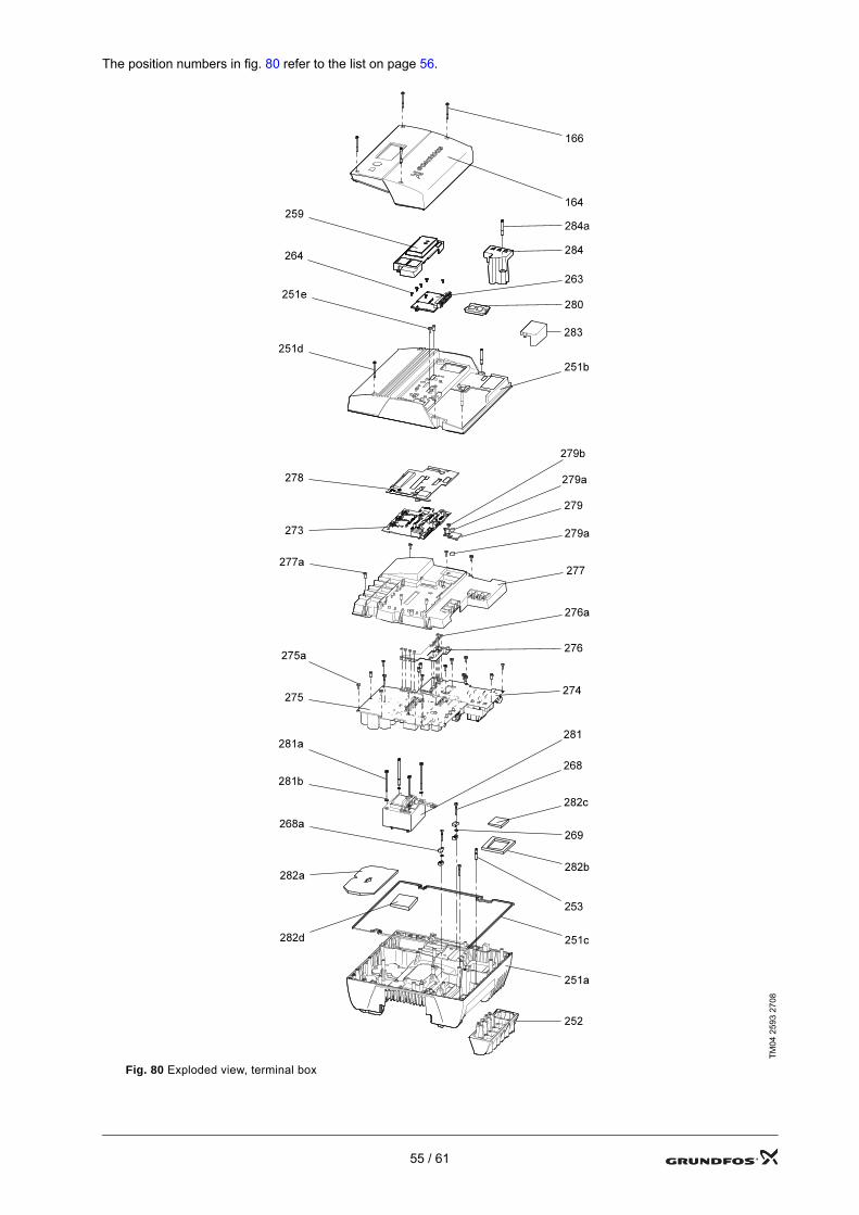
The position numbers in fig. 80 refer to the list on page 56.
TM04
259
3 27
08
Fig. 80 Exploded view, terminal box
55 / 61
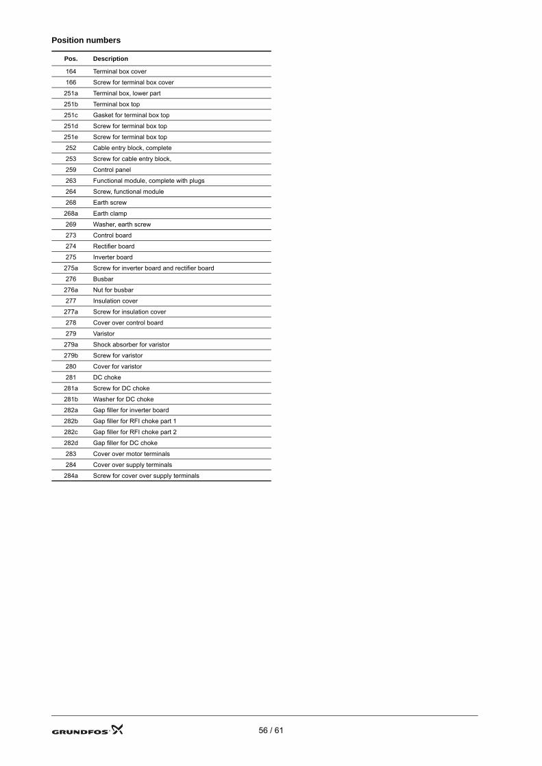
Position numbers
Pos. Description
164 Terminal box cover
166 Screw for terminal box cover
251a Terminal box, lower part
251b Terminal box top
251c Gasket for terminal box top
251d Screw for terminal box top
251e Screw for terminal box top
252 Cable entry block, complete
253 Screw for cable entry block,
259 Control panel
263 Functional module, complete with plugs
264 Screw, functional module
268 Earth screw
268a Earth clamp
269 Washer, earth screw
273 Control board
274 Rectifier board
275 Inverter board
275a Screw for inverter board and rectifier board
276 Busbar
276a Nut for busbar
277 Insulation cover
277a Screw for insulation cover
278 Cover over control board
279 Varistor
279a Shock absorber for varistor
279b Screw for varistor
280 Cover for varistor
281 DC choke
281a Screw for DC choke
281b Washer for DC choke
282a Gap filler for inverter board
282b Gap filler for RFI choke part 1
282c Gap filler for RFI choke part 2
282d Gap filler for DC choke
283 Cover over motor terminals
284 Cover over supply terminals
284a Screw for cover over supply terminals
56 / 61

TM04
216
9 21
08
Fig. 81 Block diagram
Tem
p.
Con
trol b
oard
VD
E 16
0pr
otec
tion
L1 L2 L3
Earth
A B CM
G L
arge
Mot
or
11-2
2Kw
H/L
Gat
e D
river
BE
Mic
ro
”V85
0”
REF
4.7
5V
+24V
+15V
+5V
-6V
+5V
Cur
rent
Sens
or
x 3
FE M
icro
NTC
Faul
t D
etec
tion
+24V
+5V
+5V
S
+28V
S
LDC
Ala
rm
rela
y x2
230V
ac
I/OA
dd o
nJ11
Con
trol
Boa
rd
Inve
rter
Boa
rdR
ecti
fier
boa
rd
PTC
MM
I ad
d on
J7
Com
. A
dd o
nJ10
EEPR
OM
Inru
sh
Res
etci
rcui
t
+28V
S+5
VS
+28V
S+5
VS
+7V+5V
+5V
+3.5
V
+5V
Fiel
d B
usR
XD
IR TX +5V
S
Dig
ital_
IN_1
GN
DS
Setp
oint
10V
SG
ND
S
Bas
icus
e
RX
D28
VS
Serv
ice_
5V
SB
lock
TXD
GN
DS
Serv
ice
port
Tem
p. re
ctifi
erN
TC
NET
_IN
_mea
sure
Wat
ch d
ocR
eset
NTC
Tem
p.
Inve
rter
Com
. FE/
BE
RX
.TX
.
+5V
S
Earth
Net
Inpu
t
Udc
. Mea
sure
Step
Dow
n V
olta
ge
+ 3.5V+ 5V
+5V
+5V
+5V
S
Step
Dow
n V
olta
geIcSM
PS
+24V
-6V+28
VS
+ 5VS R
EF. 4
.1V
2.2R
_
8mm
cre
pag
e (S
ELV
)
PCB
GN
DS
GN
D
Supp
ly o
ut
Supp
ly in
10 V
S
Vol
tage
Reg
ulat
or
+7V
+3.5
V+5
v+1
5v
Step
Dow
n V
olta
geSt
ep D
own
Vol
tage
57 / 61
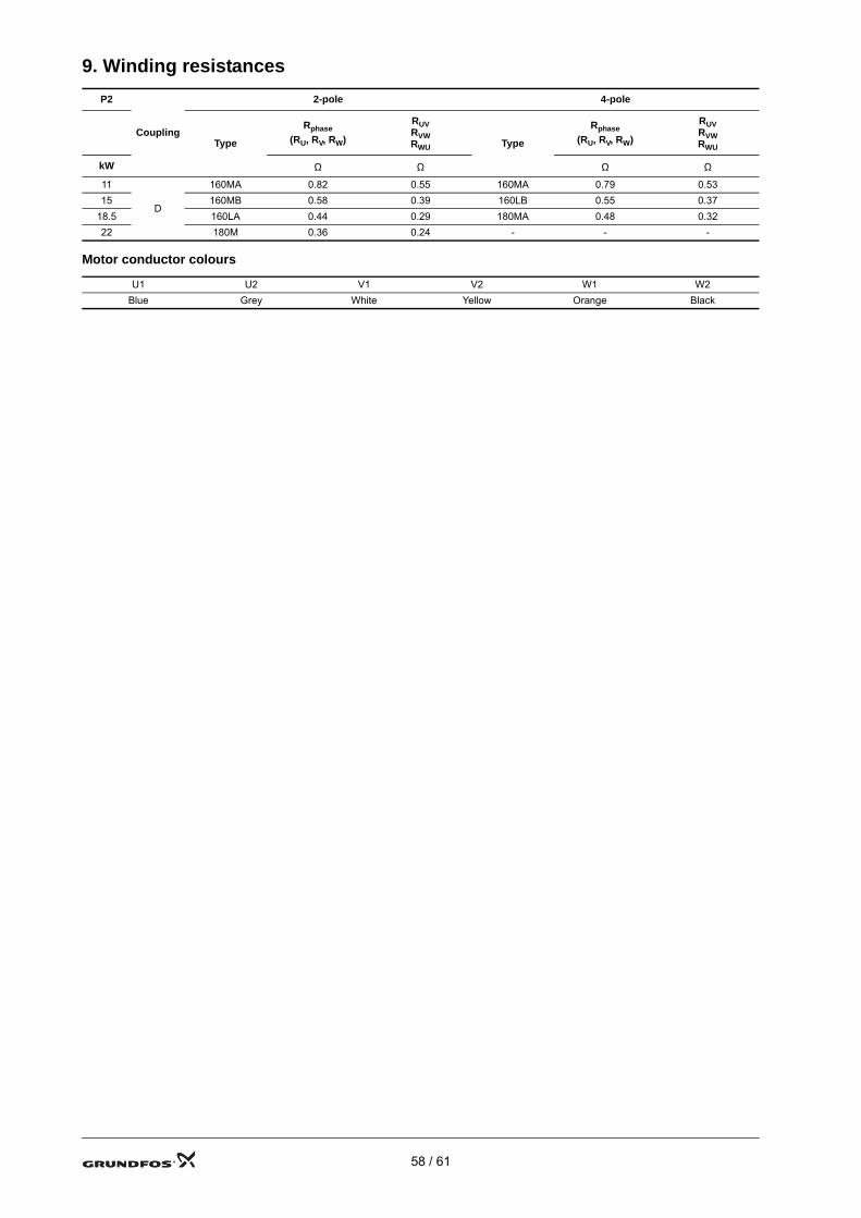
9. Winding resistances
Motor conductor colours
P2
Coupling
2-pole 4-pole
Type
Rphase(RU, RV, RW)
RUV RVW RWU Type
Rphase(RU, RV, RW)
RUV RVW RWU
kW Ω Ω Ω Ω11
D
160MA 0.82 0.55 160MA 0.79 0.5315 160MB 0.58 0.39 160LB 0.55 0.37
18.5 160LA 0.44 0.29 180MA 0.48 0.3222 180M 0.36 0.24 - - -
U1 U2 V1 V2 W1 W2Blue Grey White Yellow Orange Black
58 / 61
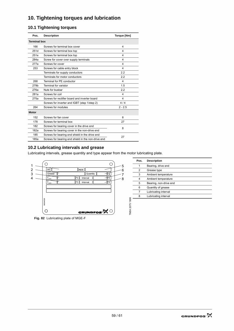
10. Tightening torques and lubrication
10.1 Tightening torques
10.2 Lubricating intervals and greaseLubricating intervals, grease quantity and type appear from the motor lubricating plate.
Pos. Description Torque [Nm]
Terminal box
166 Screws for terminal box cover 4251d Screws for terminal box top 4251e Screws for terminal box top 4284a Screw for cover over supply terminals 4277a Screws for cover 4253 Screws for cable entry block 4
Terminals for supply conductors 2.2Terminals for motor conductors 2.2
268 Terminal for PE conductor 4279b Terminal for varistor 1.5276a Nuts for busbar 2.2281a Screws for coil 4275a Screws for rectifier board and inverter board 4
Screws for inverter and IGBT (step 1/step 2) 4 / 4264 Screws for modules 2 - 2.5
Motor
152 Screws for fan cover 8178 Screws for terminal box 27182 Screws for bearing cover in the drive end
8182a Screws for bearing cover in the non-drive end185 Screws for bearing end shield in the drive end
27185a Screws for bearing end shield in the non-drive end
TM04
207
5 19
08
Pos. Description
1 Bearing, drive end2 Grease type3 Ambient temperature4 Ambient temperature5 Bearing, non-drive end6 Quantity of grease7 Lubricating interval8 Lubricating interval
Fig. 82 Lubricating plate of MGE-F
1234
5678
59 / 61
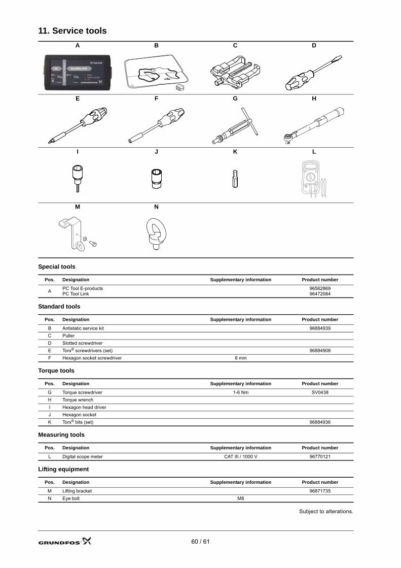
11. Service tools
Special tools
Standard tools
Torque tools
Measuring tools
Lifting equipment
A B C D
E F G H
I J K L
M N
Pos. Designation Supplementary information Product number
A PC Tool E-productsPC Tool Link
9656286996472084
Pos. Designation Supplementary information Product number
B Antistatic service kit 96884939C PullerD Slotted screwdriverE Torx® screwdrivers (set) 96884908F Hexagon socket screwdriver 8 mm
Pos. Designation Supplementary information Product number
G Torque screwdriver 1-6 Nm SV0438H Torque wrenchI Hexagon head driverJ Hexagon socketK Torx® bits (set) 96884936
Pos. Designation Supplementary information Product number
L Digital scope meter CAT III / 1000 V 96770121
Pos. Designation Supplementary information Product number
M Lifting bracket 96871735N Eye bolt M8
Subject to alterations.
60 / 61

61 / 6196810157 1209 GB 61
ArgentinaBombas GRUNDFOS de Argentina S.A.Ruta Panamericana km. 37.500 Lote 34A1619 - GarinPcia. de Buenos AiresPhone: +54-3327 414 444Telefax: +54-3327 411 111
AustraliaGRUNDFOS Pumps Pty. Ltd. P.O. Box 2040 Regency Park South Australia 5942 Phone: +61-8-8461-4611 Telefax: +61-8-8340 0155
AustriaGRUNDFOS Pumpen Vertrieb Ges.m.b.H.Grundfosstraße 2 A-5082 Grödig/Salzburg Tel.: +43-6246-883-0 Telefax: +43-6246-883-30
BelgiumN.V. GRUNDFOS Bellux S.A. Boomsesteenweg 81-83 B-2630 Aartselaar Tél.: +32-3-870 7300 Télécopie: +32-3-870 7301
BelorussiaПредставительство ГРУНДФОС в Минске220123, Минск,ул. В. Хоружей, 22, оф. 1105 Тел.: +(37517) 233 97 65, Факс: +(37517) 233 97 69E-mail: [email protected]
Bosnia/HerzegovinaGRUNDFOS SarajevoTrg Heroja 16,BiH-71000 SarajevoPhone: +387 33 713 290Telefax: +387 33 659 079e-mail: [email protected]
BrazilMark GRUNDFOS Ltda.Av. Humberto de Alencar Castelo Branco, 630CEP 09850 - 300São Bernardo do Campo - SPPhone: +55-11 4393 5533Telefax: +55-11 4343 5015
BulgariaGRUNDFOS Pumpen VertriebRepresentative Office - BulgariaBulgaria, 1421 SofiaLozenetz District105-107 Arsenalski blvd. Phone: +359 2963 3820, 2963 5653Telefax: +359 2963 1305
CanadaGRUNDFOS Canada Inc. 2941 Brighton Road Oakville, Ontario L6H 6C9 Phone: +1-905 829 9533 Telefax: +1-905 829 9512
ChinaGRUNDFOS Pumps (Shanghai) Co. Ltd.51 Floor, Raffles CityNo. 268 Xi Zang Road. (M)Shanghai 200001PRCPhone: +86-021-612 252 22Telefax: +86-021-612 253 33
CroatiaGRUNDFOS CROATIA d.o.o.Cebini 37, BuzinHR-10010 ZagrebPhone: +385 1 6595 400 Telefax: +385 1 6595 499www.grundfos.hr
Czech RepublicGRUNDFOS s.r.o.Čajkovského 21779 00 OlomoucPhone: +420-585-716 111Telefax: +420-585-716 299
DenmarkGRUNDFOS DK A/S Martin Bachs Vej 3 DK-8850 Bjerringbro Tlf.: +45-87 50 50 50 Telefax: +45-87 50 51 51 E-mail: [email protected]/DK
EstoniaGRUNDFOS Pumps Eesti OÜPeterburi tee 92G11415 TallinnTel: + 372 606 1690Fax: + 372 606 1691
FinlandOY GRUNDFOS Pumput AB Mestarintie 11 FIN-01730 Vantaa Phone: +358-3066 5650 Telefax: +358-3066 56550
FrancePompes GRUNDFOS Distribution S.A. Parc d’Activités de Chesnes 57, rue de Malacombe F-38290 St. Quentin Fallavier (Lyon) Tél.: +33-4 74 82 15 15 Télécopie: +33-4 74 94 10 51
GermanyGRUNDFOS GMBHSchlüterstr. 3340699 ErkrathTel.: +49-(0) 211 929 69-0 Telefax: +49-(0) 211 929 69-3799e-mail: [email protected] in Deutschland:e-mail: [email protected]
GreeceGRUNDFOS Hellas A.E.B.E. 20th km. Athinon-Markopoulou Av. P.O. Box 71 GR-19002 Peania Phone: +0030-210-66 83 400 Telefax: +0030-210-66 46 273
Hong KongGRUNDFOS Pumps (Hong Kong) Ltd. Unit 1, Ground floor Siu Wai Industrial Centre 29-33 Wing Hong Street & 68 King Lam Street, Cheung Sha Wan Kowloon Phone: +852-27861706 / 27861741 Telefax: +852-27858664
HungaryGRUNDFOS Hungária Kft.Park u. 8H-2045 Törökbálint, Phone: +36-23 511 110Telefax: +36-23 511 111
IndiaGRUNDFOS Pumps India Private Limited118 Old Mahabalipuram RoadThoraipakkamChennai 600 096Phone: +91-44 2496 6800
IndonesiaPT GRUNDFOS Pompa Jl. Rawa Sumur III, Blok III / CC-1 Kawasan Industri, Pulogadung Jakarta 13930 Phone: +62-21-460 6909 Telefax: +62-21-460 6910 / 460 6901
IrelandGRUNDFOS (Ireland) Ltd. Unit A, Merrywell Business ParkBallymount Road LowerDublin 12 Phone: +353-1-4089 800 Telefax: +353-1-4089 830
ItalyGRUNDFOS Pompe Italia S.r.l. Via Gran Sasso 4I-20060 Truccazzano (Milano)Tel.: +39-02-95838112 Telefax: +39-02-95309290 / 95838461
JapanGRUNDFOS Pumps K.K.Gotanda Metalion Bldg., 5F, 5-21-15, Higashi-gotandaShiagawa-ku, Tokyo141-0022 JapanPhone: +81 35 448 1391Telefax: +81 35 448 9619
KoreaGRUNDFOS Pumps Korea Ltd.6th Floor, Aju Building 679-5Yeoksam-dong, Kangnam-ku, 135-916Seoul, KoreaPhone: +82-2-5317 600Telefax: +82-2-5633 725
LatviaSIA GRUNDFOS Pumps Latvia Deglava biznesa centrsAugusta Deglava ielā 60, LV-1035, Rīga,Tālr.: + 371 714 9640, 7 149 641Fakss: + 371 914 9646
LithuaniaGRUNDFOS Pumps UABSmolensko g. 6LT-03201 VilniusTel: + 370 52 395 430Fax: + 370 52 395 431
MalaysiaGRUNDFOS Pumps Sdn. Bhd.7 Jalan Peguam U1/25Glenmarie Industrial Park40150 Shah AlamSelangor Phone: +60-3-5569 2922Telefax: +60-3-5569 2866
MéxicoBombas GRUNDFOS de México S.A. de C.V. Boulevard TLC No. 15Parque Industrial Stiva AeropuertoApodaca, N.L. 66600Phone: +52-81-8144 4000 Telefax: +52-81-8144 4010
NetherlandsGRUNDFOS NetherlandsVeluwezoom 351326 AE AlmerePostbus 220151302 CA ALMERE Tel.: +31-88-478 6336 Telefax: +31-88-478 6332e-mail: [email protected]
New ZealandGRUNDFOS Pumps NZ Ltd.17 Beatrice Tinsley CrescentNorth Harbour Industrial EstateAlbany, AucklandPhone: +64-9-415 3240Telefax: +64-9-415 3250
NorwayGRUNDFOS Pumper A/S Strømsveien 344 Postboks 235, Leirdal N-1011 Oslo Tlf.: +47-22 90 47 00 Telefax: +47-22 32 21 50
PolandGRUNDFOS Pompy Sp. z o.o.ul. Klonowa 23Baranowo k. PoznaniaPL-62-081 PrzeźmierowoTel: (+48-61) 650 13 00Fax: (+48-61) 650 13 50
PortugalBombas GRUNDFOS Portugal, S.A. Rua Calvet de Magalhães, 241Apartado 1079P-2770-153 Paço de ArcosTel.: +351-21-440 76 00Telefax: +351-21-440 76 90
RomâniaGRUNDFOS Pompe România SRLBd. Biruintei, nr 103 Pantelimon county IlfovPhone: +40 21 200 4100Telefax: +40 21 200 4101E-mail: [email protected]
RussiaООО ГрундфосРоссия, 109544 Москва, ул. Школьная 39Тел. (+7) 495 737 30 00, 564 88 00Факс (+7) 495 737 75 36, 564 88 11E-mail [email protected]
Serbia GRUNDFOS Predstavništvo BeogradDr. Milutina Ivkovića 2a/29YU-11000 Beograd Phone: +381 11 26 47 877 / 11 26 47 496Telefax: +381 11 26 48 340
SingaporeGRUNDFOS (Singapore) Pte. Ltd. 24 Tuas West Road Jurong Town Singapore 638381 Phone: +65-6865 1222 Telefax: +65-6861 8402
SloveniaGRUNDFOS PUMPEN VERTRIEB Ges.m.b.H.,Podružnica LjubljanaŠlandrova 8b, SI-1231 Ljubljana-ČrnučePhone: +386 1 568 0610Telefax: +386 1 568 0619E-mail: [email protected]
SpainBombas GRUNDFOS España S.A. Camino de la Fuentecilla, s/n E-28110 Algete (Madrid) Tel.: +34-91-848 8800 Telefax: +34-91-628 0465
SwedenGRUNDFOS AB Box 333 (Lunnagårdsgatan 6) 431 24 Mölndal Tel.: +46(0)771-32 23 00 Telefax: +46(0)31-331 94 60
SwitzerlandGRUNDFOS Pumpen AG Bruggacherstrasse 10 CH-8117 Fällanden/ZH Tel.: +41-1-806 8111 Telefax: +41-1-806 8115
TaiwanGRUNDFOS Pumps (Taiwan) Ltd. 7 Floor, 219 Min-Chuan Road Taichung, Taiwan, R.O.C. Phone: +886-4-2305 0868Telefax: +886-4-2305 0878
ThailandGRUNDFOS (Thailand) Ltd. 92 Chaloem Phrakiat Rama 9 Road,Dokmai, Pravej, Bangkok 10250Phone: +66-2-725 8999Telefax: +66-2-725 8998
TurkeyGRUNDFOS POMPA San. ve Tic. Ltd. Sti.Gebze Organize Sanayi Bölgesi Ihsan dede Caddesi,2. yol 200. Sokak No. 20441490 Gebze/ KocaeliPhone: +90 - 262-679 7979Telefax: +90 - 262-679 7905E-mail: [email protected]
UkraineТОВ ГРУНДФОС УКРАЇНА 01010 Київ, Вул. Московська 8б, Тел.:(+38 044) 390 40 50 Фах.: (+38 044) 390 40 59E-mail: [email protected]
United Arab EmiratesGRUNDFOS Gulf DistributionP.O. Box 16768Jebel Ali Free ZoneDubaiPhone: +971-4- 8815 166Telefax: +971-4-8815 136
United KingdomGRUNDFOS Pumps Ltd. Grovebury Road Leighton Buzzard/Beds. LU7 8TL Phone: +44-1525-850000 Telefax: +44-1525-850011
U.S.A.GRUNDFOS Pumps Corporation 17100 West 118th TerraceOlathe, Kansas 66061Phone: +1-913-227-3400 Telefax: +1-913-227-3500
UsbekistanПредставительство ГРУНДФОС в Ташкенте700000 Ташкент ул.Усмана Носира 1-й тупик 5Телефон: (3712) 55-68-15Факс: (3712) 53-36-35
Addresses revised 15.06.2009