Embed Size (px)
Citation preview

Metrology for additive manufacturing
Professor Richard Leach Chair in Metrology Manufacturing Metrology Team, Faculty of Engineering www.nottingham.ac.uk/research/manufacturing-metrology
What is today about?
• To inform the community about the research at Nottingham – including the results of recent reviews
• To highlight research at University of Huddersfield, NPL and MTC
• To get feedback on our approach
The fellowship
• EPSRC Manufacturing Fellowship
• March 2015 to March 2020
• Total of £1.5m funding + leverage (£4.2m)
• Supports fellow (60%), 2 research fellows, equipment and impact activities
• Faculty support for 1 research fellow (2 years), 1 lecturer, 7 PhD students
• Letters of support from 5 academics, 3 research institutes and 14 industrials
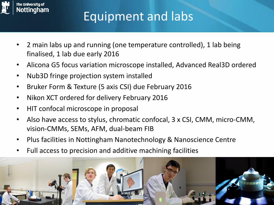
Equipment and labs
• 2 main labs up and running (one temperature controlled), 1 lab being finalised, 1 lab due early 2016
• Alicona G5 focus variation microscope installed, Advanced Real3D ordered
• Nub3D fringe projection system installed
• Bruker Form & Texture (5 axis CSI) due February 2016
• Nikon XCT ordered for delivery February 2016
• HIT confocal microscope in proposal
• Also have access to stylus, chromatic confocal, 3 x CSI, CMM, micro-CMM, vision-CMMs, SEMs, AFM, dual-beam FIB
• Plus facilities in Nottingham Nanotechnology & Nanoscience Centre
• Full access to precision and additive machining facilities
Plans
• Develop the next-generation of techniques for measuring complex form of AM parts
• Develop techniques for measuring surface texture of AM parts and move towards a mapping of process variables to texture
• Develop x-ray computed tomography for the measurement of internal form and texture of AM parts
• Develop in-process/in-line techniques for dimensional and defect measurement (existing work = OCT, SRAS, fringe projection, plastic & metal)
• Develop a calibration and performance verification infrastructure for the techniques above, including uncertainty estimation
Early outputs
• Stavroulakis P, Leach R K 2016 Review of post-process optical form metrology for industrial-grade metal additive manufactured components Rev. Sci. Instrum. under review
• Everton S K, Hirsch M, Stavroulakis P, Leach R K, Clare A T 2016 Review of in-situ process monitoring and in-situ metrology for additive manufacturing Materials and Design under review
• Thompson A, Maskery I, Leach R K 2016 X-ray computed tomography for additive manufacture: a review Meas. Sci. Technol. to be submitted by Christmas
• Townsend A, Senin N, Blunt L A, Leach R K, Taylor J 2016 Review of surface texture measurement for additive manufacturing, to be submitted by Christmas
How can you engage?
• Support PhD research (so far NPL, MTC, 3T RPD, Nikon, Bruker, RAL, Alicona)
• Support research fellows • Supply equipment • Allow access to equipment (metrology and
manufacturing) • Industrial internships, including KTPs • Feedback metrology requirements • Provide case studies (especially components to
be measured or in-line scenarios) • Get involved in the research (especially towards
joint publications)
Agenda
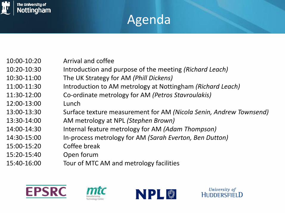
10:00-10:20 Arrival and coffee 10:20-10:30 Introduction and purpose of the meeting (Richard Leach) 10:30-11:00 The UK Strategy for AM (Phill Dickens) 11:00-11:30 Introduction to AM metrology at Nottingham (Richard Leach) 11:30-12:00 Co-ordinate metrology for AM (Petros Stavroulakis) 12:00-13:00 Lunch 13:00-13:30 Surface texture measurement for AM (Nicola Senin, Andrew Townsend) 13:30-14:00 AM metrology at NPL (Stephen Brown) 14:00-14:30 Internal feature metrology for AM (Adam Thompson) 14:30-15:00 In-process metrology for AM (Sarah Everton, Ben Dutton) 15:00-15:20 Coffee break 15:20-15:40 Open forum 15:40-16:00 Tour of MTC AM and metrology facilities
Metrology for additive manufacturing
Professor Richard Leach Chair in Metrology Manufacturing Metrology Team, Faculty of Engineering www.nottingham.ac.uk/research/manufacturing-metrology
Something missing?
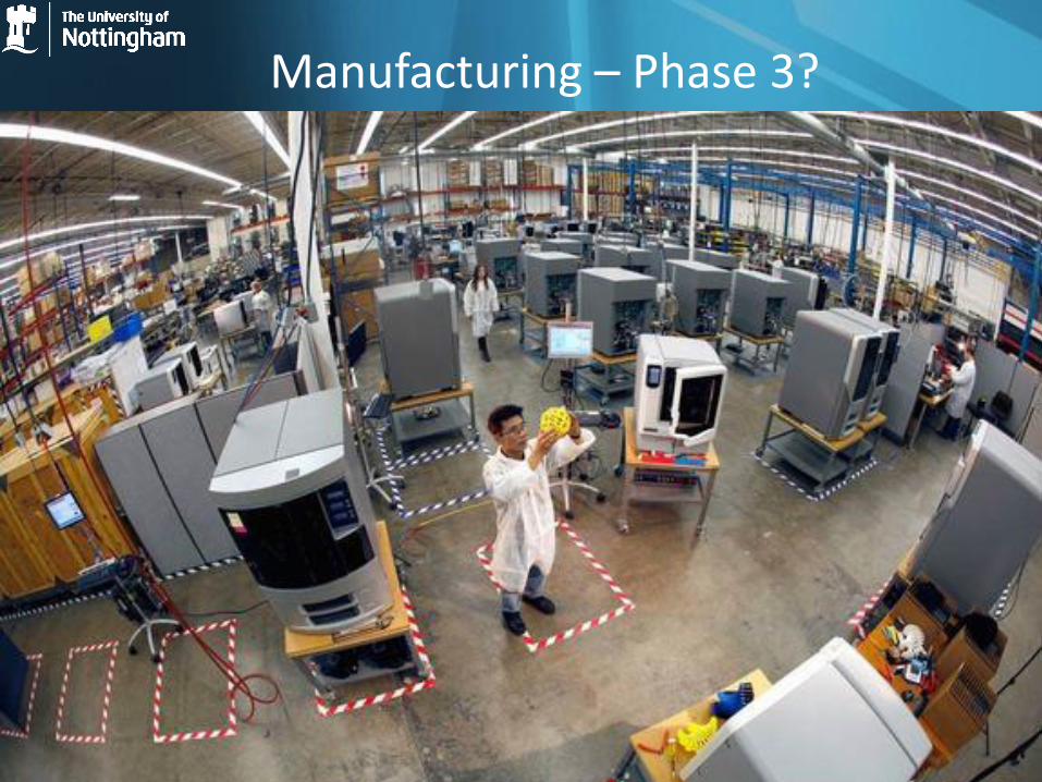
• With AM we can make some highly-complex components and even assemblies
• But what about QUALITY?
• So far, most people involved in AM have never heard of the word TOLERANCE
• All mature production processes have suitable quality systems in place
• Why should this be different for AM?
Why measure?
• To know whether a part is fit-for-purpose – tolerances and functionality
• To allow assembly of complex components
• To allow control of a manufacturing process
• To avoid unnecessary scrap material and redundant processing time - cost, environment
• To improve energy-efficiency
• To give “customers” confidence in a product
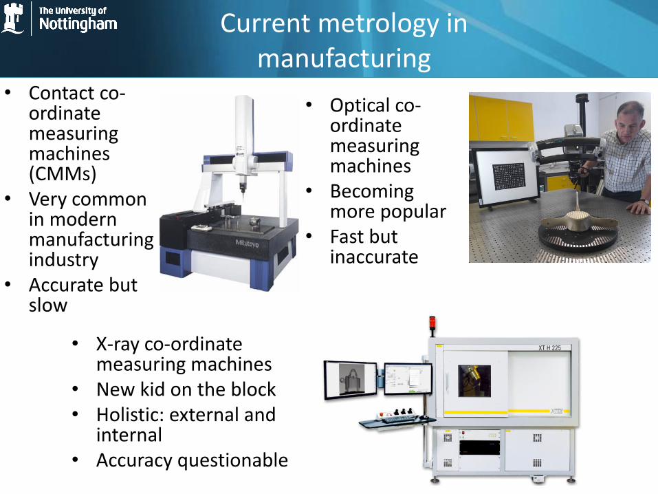
Current metrology in manufacturing
• Contact co-ordinate measuring machines (CMMs)
• Very common in modern manufacturing industry
• Accurate but slow
• Optical co-ordinate measuring machines
• Becoming more popular
• Fast but inaccurate
• X-ray co-ordinate measuring machines
• New kid on the block • Holistic: external and
internal • Accuracy questionable
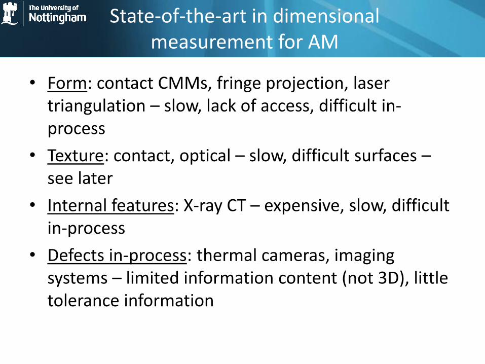
State-of-the-art in dimensional measurement for AM
• Form: contact CMMs, fringe projection, laser triangulation – slow, lack of access, difficult in-process
• Texture: contact, optical – slow, difficult surfaces – see later
• Internal features: X-ray CT – expensive, slow, difficult in-process
• Defects in-process: thermal cameras, imaging systems – limited information content (not 3D), little tolerance information
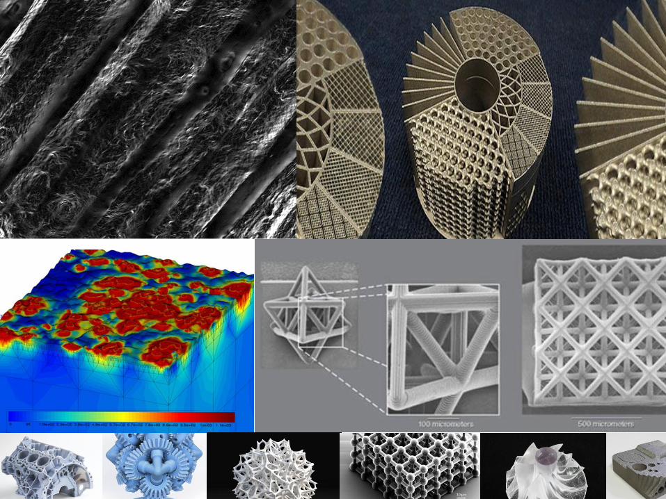
Why is AM an issue for metrology?
• With almost infinite design freedom, comes almost infinitely complex shapes to measure!
• Complex surface texture – very high slope angles
• Huge range of materials – plastics, metals, ceramics, … growing daily
• The need for speed!
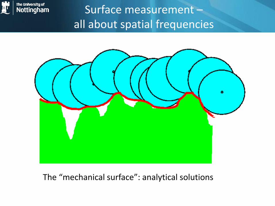
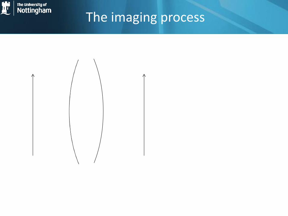
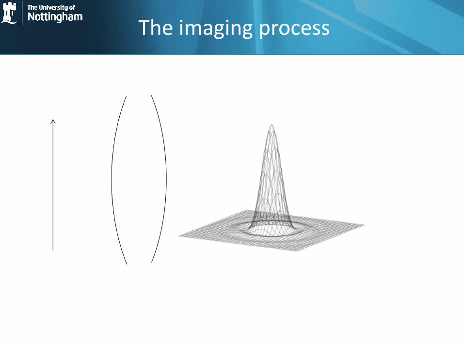
Surface measurement – all about spatial frequencies
The “mechanical surface”: analytical solutions
Why use optical and not contact?
• Contact always causes damage, although this is often over-emphasised
• Optical can be much faster – in-line solutions become practical
• For coordinate metrology, optical systems give a large set of point cloud data rather than a few carefully-chosen points
• Optical instruments can be easier to use – this is a critical point – see next slide
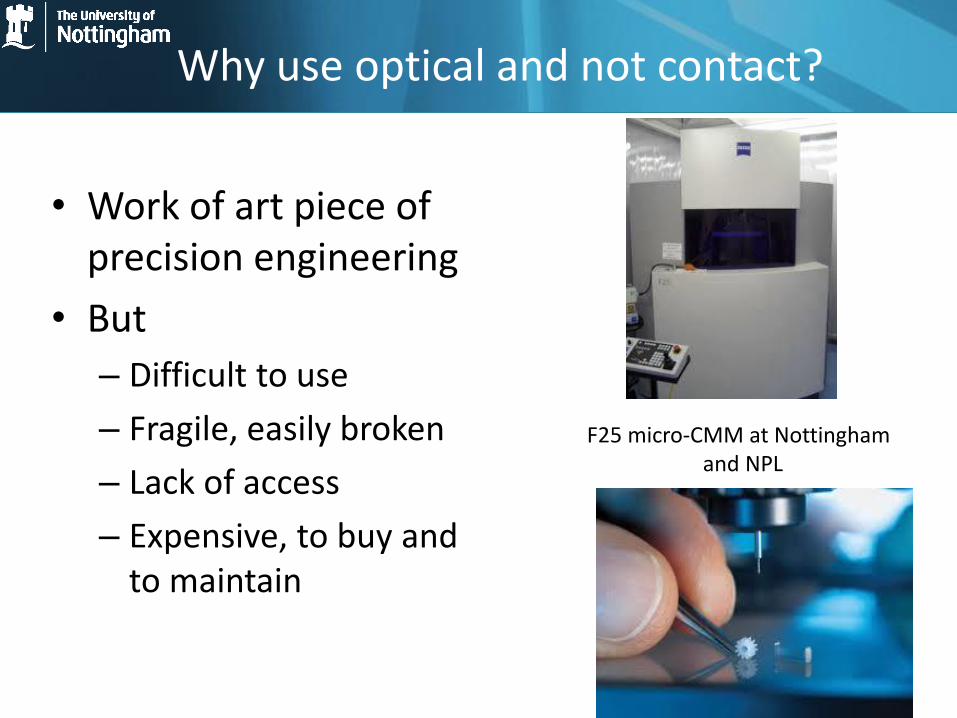
Why use optical and not contact?
• Work of art piece of precision engineering
• But
– Difficult to use
– Fragile, easily broken
– Lack of access
– Expensive, to buy and to maintain
F25 micro-CMM at Nottingham and NPL

Optical instruments - basics
• Light reflected from a surface and the returned amplitude (and phase) data interrogated
• Can vary depending on:
– Incident angle (spatial bandwidth)
– Source spectrum (temporal bandwidth)
– Degree of coherence
– Polarisation state
Optical instruments - limitations
• Finite spatial frequency bandwidth due to diffraction limit and/or pixel size/density
• Finite range due to imaging and detection apertures
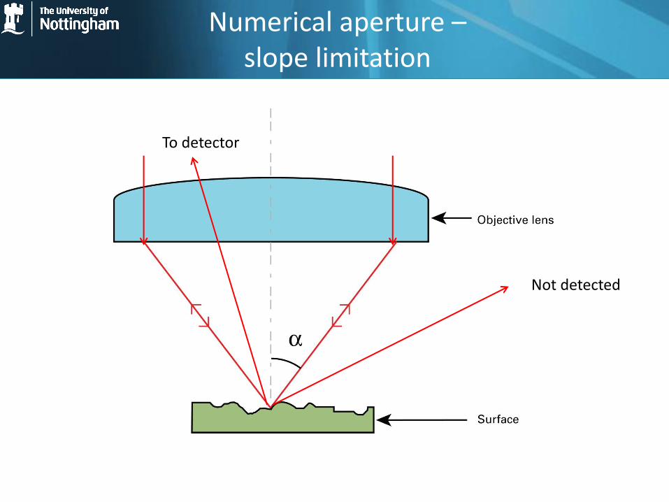
• Slope limitation due to finite angular collection system
• Aberrations in the optics leading to “optical artefacts” – these are often due to non-linear affects and difficult to predict and/or correct
• Speed issues due to need for scanning (mechanical or wavelength)
• Big data!
• Lack of standardisation
• ….
“Information-rich metrology” (IRM)
IRM = Rigorous models of the instrument-surface interaction, often including all the nasty non-linear parts + Information about the object being measured, e.g. CAD data, course measurements, manufacturing specifications, …
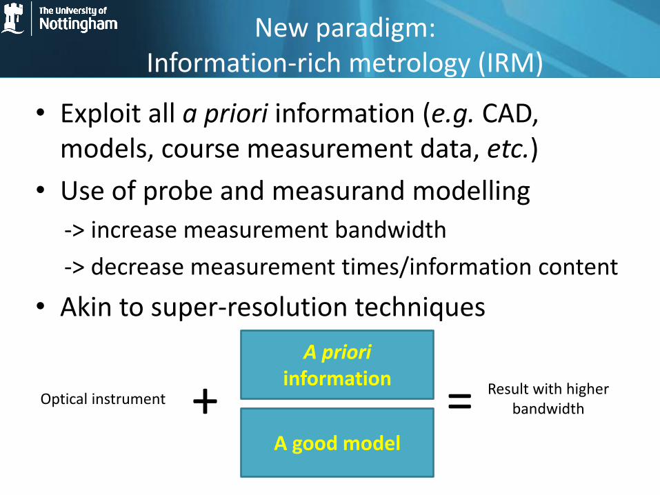
New paradigm: Information-rich metrology (IRM)
• Exploit all a priori information (e.g. CAD, models, course measurement data, etc.)
• Use of probe and measurand modelling
-> increase measurement bandwidth
-> decrease measurement times/information content
• Akin to super-resolution techniques
A priori information
Optical instrument + = A good model
Result with higher bandwidth
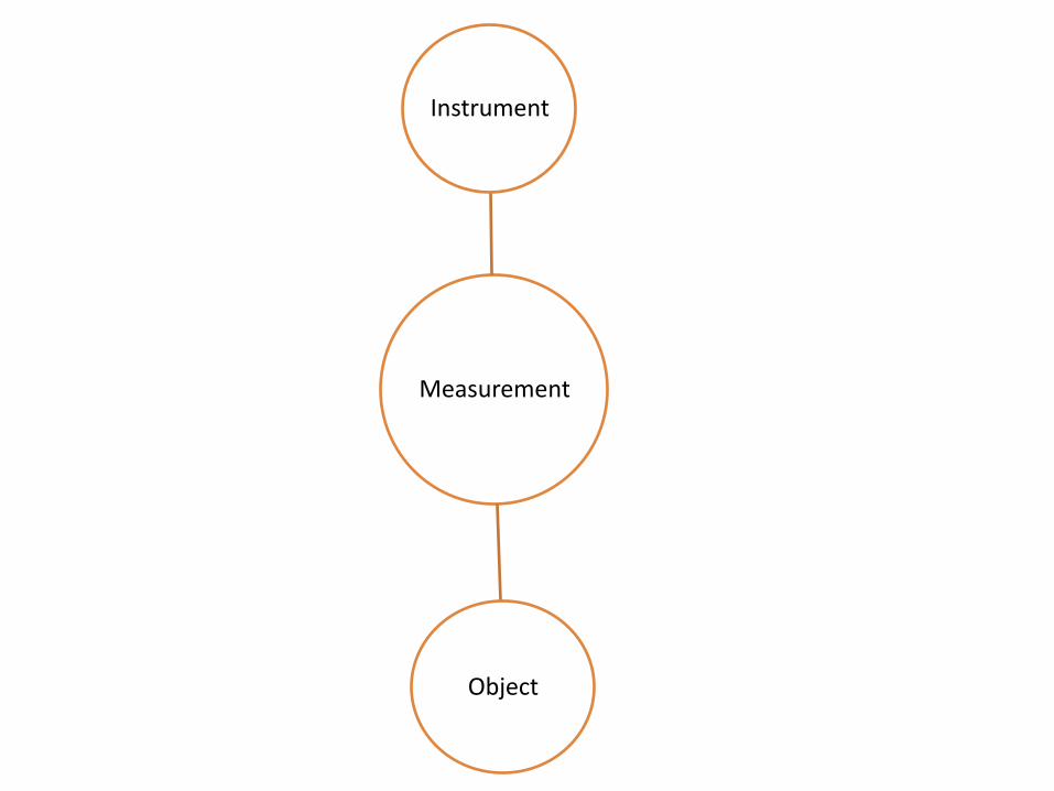
Measurement
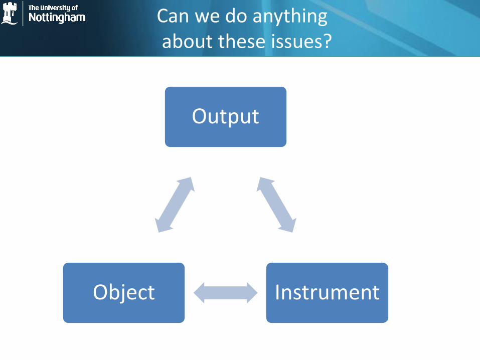
Instrument
Object
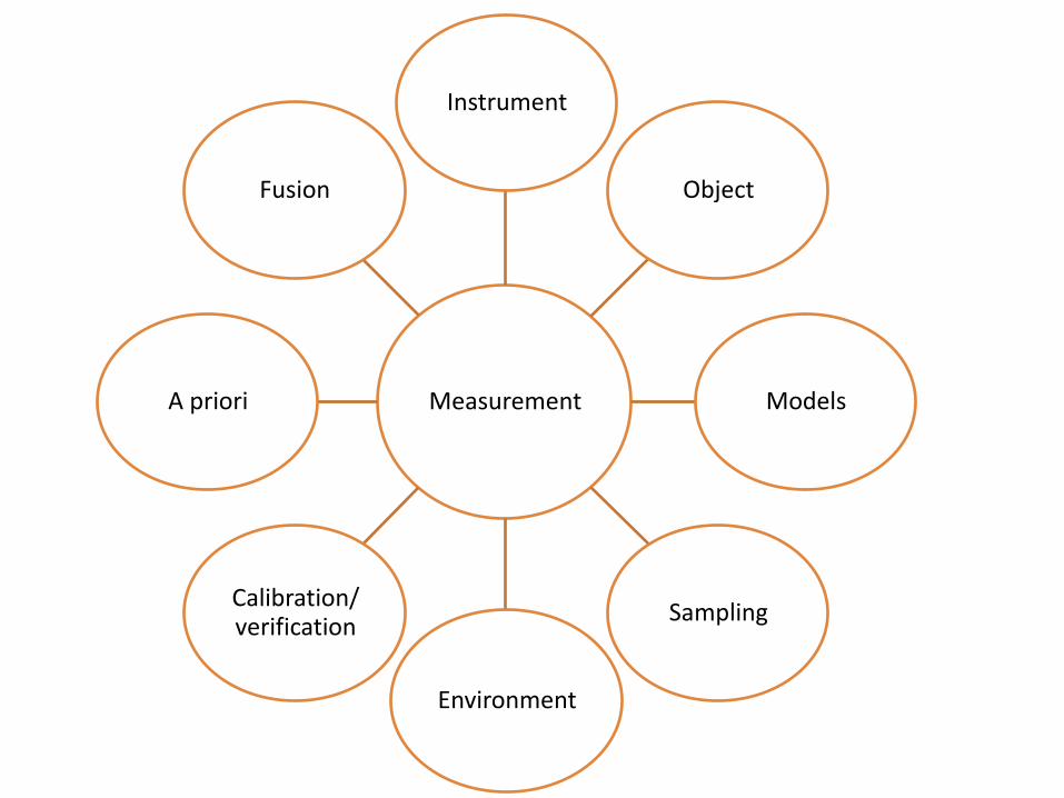
Measurement
Instrument
Object
Models
Sampling
Environment
Calibration/ verification
A priori
Fusion
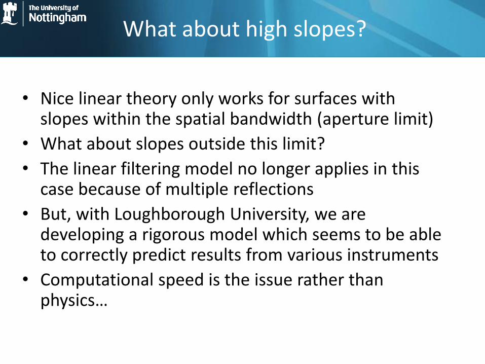
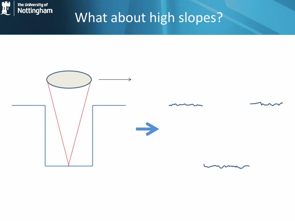
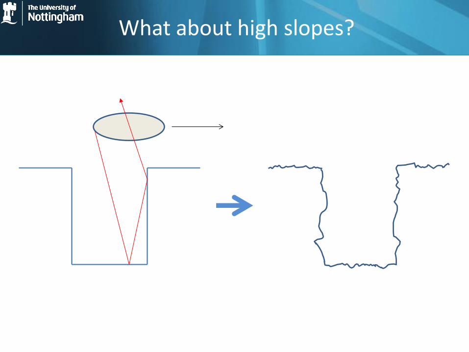
What about high slopes?
• Nice linear theory only works for surfaces with slopes within the spatial bandwidth (aperture limit)
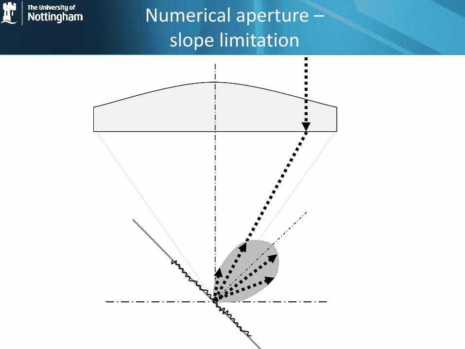
• What about slopes outside this limit?
• The linear filtering model no longer applies in this case because of multiple reflections
• But, with Loughborough University, we are developing a rigorous model which seems to be able to correctly predict results from various instruments
• Computational speed is the issue rather than physics…
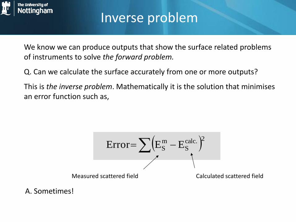
We know we can produce outputs that show the surface related problems of instruments to solve the forward problem.
Q. Can we calculate the surface accurately from one or more outputs?
This is the inverse problem. Mathematically it is the solution that minimises an error function such as,
2.calc
SmS EEError
Measured scattered field Calculated scattered field
A. Sometimes!
Inverse problem

Object: 15 m step with a 5 m
x 1 m groove. Illumination
from the top.
New object calculated from
CSI data using updated
model shows the profile of
the “vertical wall”
CSI results: top
and bottom
surfaces are found
Optical trickery?
“It's never too late to start over!”
• The use of a priori manufacturing data gives us a wealth of information to exploit
• Combine this with rigorous modelling and we can significantly enhance measurements
• Often this involves non-linear optimization and 3D solvers -> need to look at fast approaches
• IRM will form the focus to build a world-leading, game-changing team at Nottingham
Questions
• Are we taking the right approach?
• Have we got the appropriate team and partners?
• Have we missed anything critical?
• What about the materials metrology?
• Is the UK appropriately embedded in the standards infrastructure?
• Should we do something like this regularly? If yes, how regularly?