Embed Size (px)
Citation preview

VGP MStmt Ver2014(Jan) Page 1
METHOD STATEMENT
FOR
ELMICH GREEN WALL
VERSIWALL® GP (VGP) TRAY PLANTER
PREPARED BY ELMICH PTE LTD
VGP MStmt Ver2014(Jan) Page 2
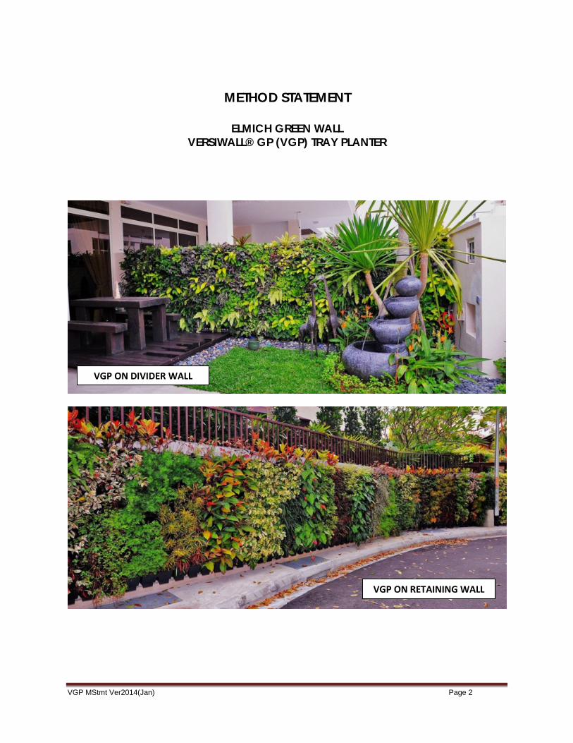
METHOD STATEMENT
ELMICH GREEN WALL VERSIWALL® GP (VGP) TRAY PLANTER
VGP ON DIVIDER WALL
VGP ON RETAINING WALL
VGP MStmt Ver2014(Jan) Page 3
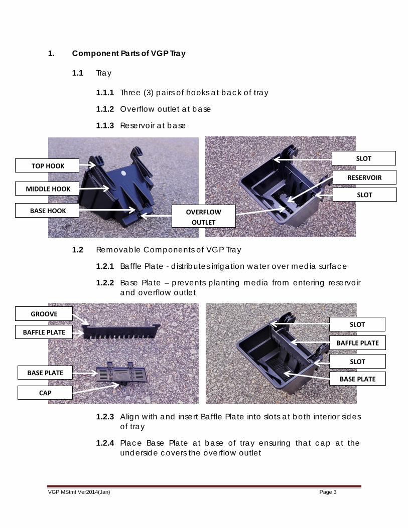
1. Component Parts of VGP Tray 1.1 Tray
1.1.1 Three (3) pairs of hooks at back of tray
1.1.2 Overflow outlet at base
1.1.3 Reservoir at base
1.2 Removable Components of VGP Tray
1.2.1 Baffle Plate - distributes irrigation water over media surface
1.2.2 Base Plate – prevents planting media from entering reservoir and overflow outlet
1.2.3 Align with and insert Baffle Plate into slots at both interior sides of tray
1.2.4 Place Base Plate at base of tray ensuring that cap at the underside covers the overflow outlet
BAFFLE PLATE
BASE PLATE BASE PLATE
BAFFLE PLATE
SLOT
OVERFLOW OUTLET
TOP HOOK
CAP
RESERVOIR MIDDLE HOOK
BASE HOOK
SLOT
SLOT
SLOT
GROOVE

VGP MStmt Ver2014(Jan) Page 4
2. Mounting Options 2.1 Proprietary Mounting Panel
2.1.1 Configured to precisely match mounting hooks of tray 2.1.2 Precise and secure anchorage at all 6 hook points
2.2 Welded Mesh
2.2.2 Vertical members 50mm apart and horizontal members 75mm or 150mm apart
2.3 Rods
2.3.1 Horizontal members 75mm apart
3. Wall or Mounting Frame/Stand for VGP Installation
3.1 Prime RC wall and/or construct framework (including waterproofing, painting, welding, etc) based on mounting option selected according to project requirements; or
3.2 Construct free-standing mounting frame/stand based on mounting
option selected according to project requirements
PROPRIETARY PANEL WELDED MESH RODS

VGP MStmt Ver2014(Jan) Page 5
3.3 Install Proprietary Mounting Panel 3.3.1 Pluck out C-Washer found at either end of Mounting Panel 3.3.2 Insert C-Washer where adjacent panels overlap to prevent
corner of top overlapping panel from collapsing downwards when bolt is tightened
3.4 Install Welded Mesh
3.4.1 Leave gap of 50mm between mesh and wall surface
C-WASHER BETWEEN OVERLAPPING PANELS
C-WASHER
MOUNTING PANEL
TOP OVERLAPPING PANEL COLLAPSES DOWNWARD
WITHOUT C-WASHER

VGP MStmt Ver2014(Jan) Page 6
4. Irrigation System (optional or according to project requirements)
4.1 Use a maximum of 8 trays per panel this will ensure a sufficient gap to accommodate the horizontal irrigation line.
4.2 Main irrigation tubes run vertically between trays and horizontal branch tubes run above each row. Each tray supplied by one emitter (dripper).
4.3 Secure tubes with cable ties (holes provided on panels)
4.4 Position tube connected to emitters at centre of Baffle Plate for water to be evenly distributed throughout media surface
4.5 Install controller for automated irrigation water and fertilizer release
5. Planting
5.1 Regular free draining planting soil may be used
5.2 Select appropriate indoor or outdoor plants according to design and project requirements
5.3 Planting may be in-situ or off-site
CENTRE OF BAFFLE PLATE
BETWEEN TRAYS
EMITTER
CABLE TIE
ABOVE TRAYS
VGP MStmt Ver2014(Jan) Page 7
5.4 Use basket/carton box or rack system if trays are planted off-site to facilitate easy transportation to site
6. Mounting
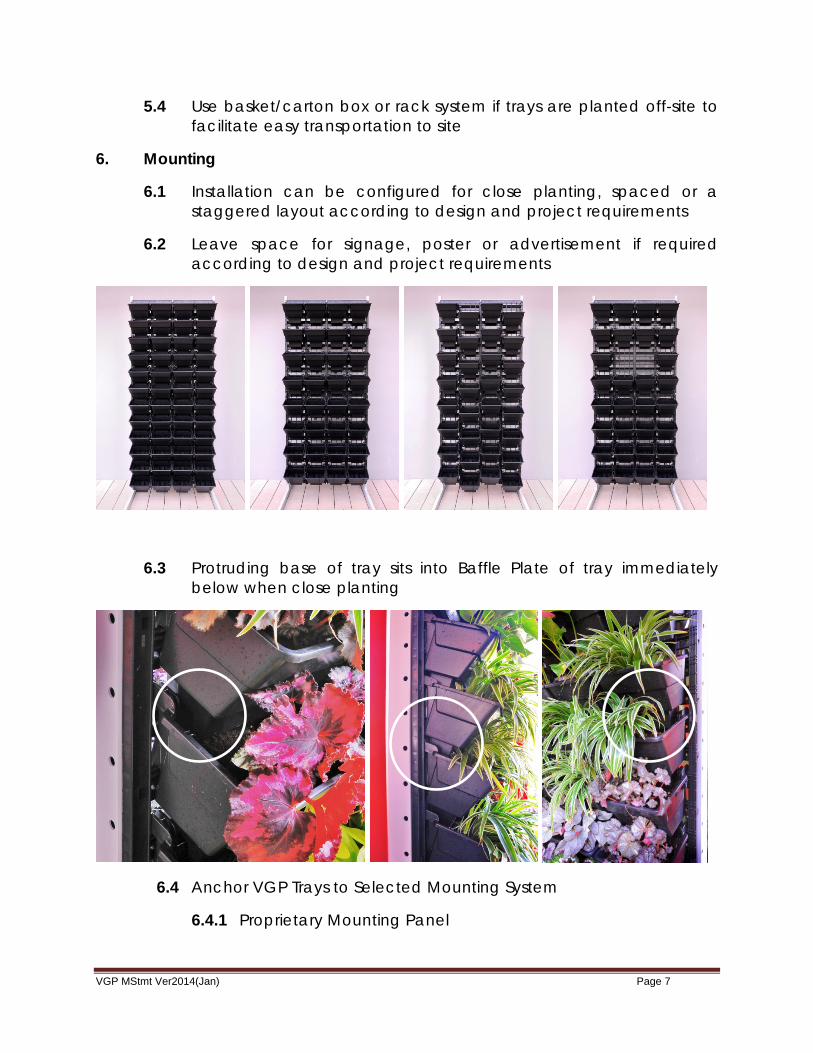
6.1 Installation can be configured for close planting, spaced or a staggered layout according to design and project requirements
6.2 Leave space for signage, poster or advertisement if required according to design and project requirements
6.3 Protruding base of tray sits into Baffle Plate of tray immediately below when close planting
6.4 Anchor VGP Trays to Selected Mounting System
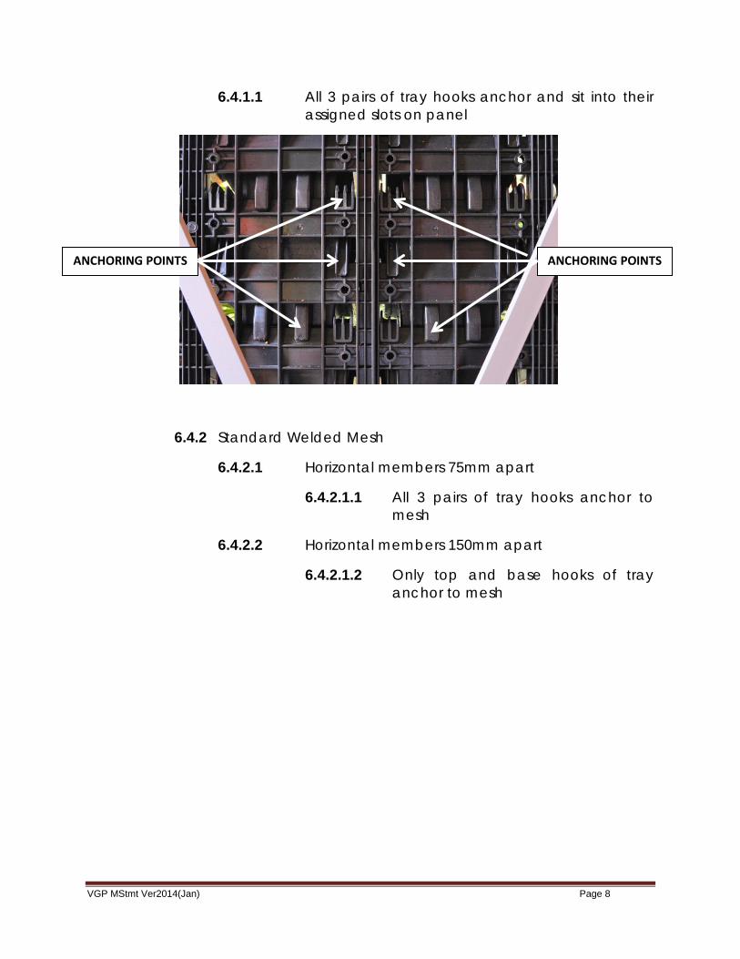
6.4.1 Proprietary Mounting Panel
VGP MStmt Ver2014(Jan) Page 8
6.4.1.1 All 3 pairs of tray hooks anchor and sit into their assigned slots on panel
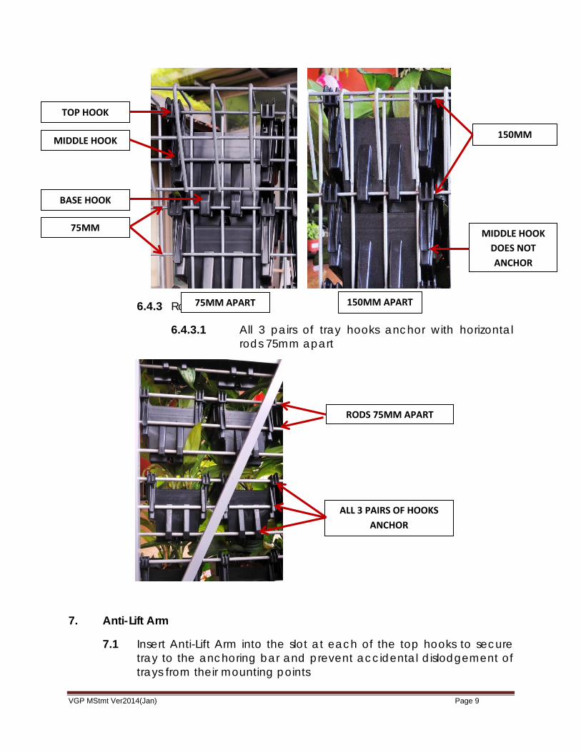
6.4.2 Standard Welded Mesh
6.4.2.1 Horizontal members 75mm apart
6.4.2.1.1 All 3 pairs of tray hooks anchor to mesh
6.4.2.2 Horizontal members 150mm apart
6.4.2.1.2 Only top and base hooks of tray anchor to mesh
ANCHORING POINTS ANCHORING POINTS
VGP MStmt Ver2014(Jan) Page 9
6.4.3 Rods
6.4.3.1 All 3 pairs of tray hooks anchor with horizontal rods 75mm apart
7. Anti-Lift Arm
7.1 Insert Anti-Lift Arm into the slot at each of the top hooks to secure tray to the anchoring bar and prevent accidental dislodgement of trays from their mounting points
RODS 75MM APART
ALL 3 PAIRS OF HOOKS ANCHOR
150MM
75MM MIDDLE HOOK DOES NOT ANCHOR
TOP HOOK
BASE HOOK
MIDDLE HOOK
75MM APART 150MM APART

VGP MStmt Ver2014(Jan) Page 10
7.2 Tuck finger-grip of Anti-Lift Arm into groove at Baffle Plate
8. Drainage
ANTI-LIFT ARM
INSERT ANTI-LIFT ARM INTO SLOT AT TOP HOOK
GROOVE AT BAFFLE PLATE
GROOVE AT BAFFLE PLATE
SLOT AT TOP HOOK
VGP MStmt Ver2014(Jan) Page 11
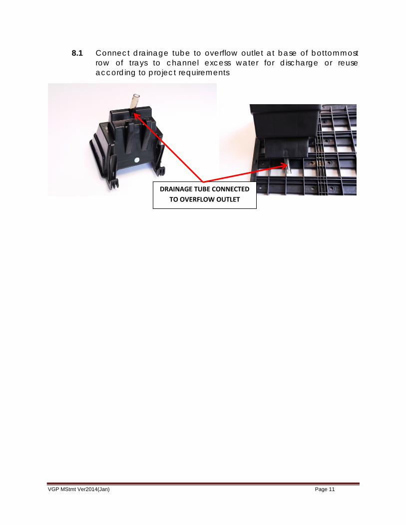
8.1 Connect drainage tube to overflow outlet at base of bottommost row of trays to channel excess water for discharge or reuse according to project requirements
DRAINAGE TUBE CONNECTED TO OVERFLOW OUTLET
VGP MStmt Ver2014(Jan) Page 12
8.2 A short length of tubing may also be connected to the overflow outlets to prevent excess water exiting the outlet of upper trays from splashing when it strikes the Baffle Plate of the lower trays in loose planting.
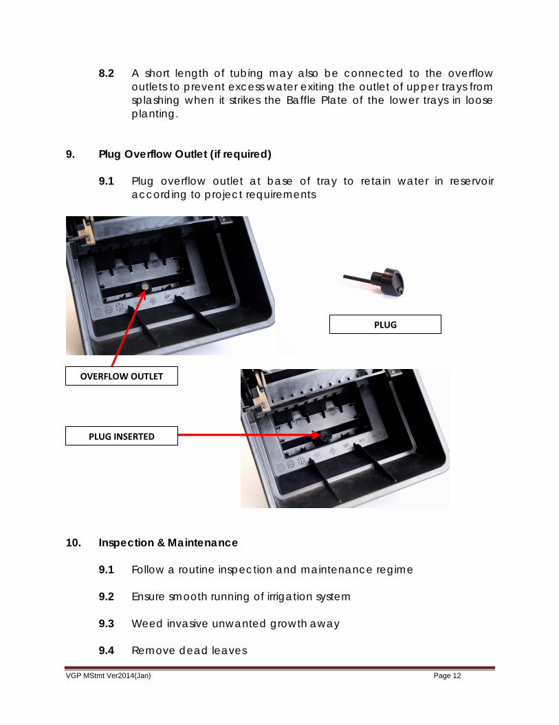
9. Plug Overflow Outlet (if required)
9.1 Plug overflow outlet at base of tray to retain water in reservoir according to project requirements
10. Inspection & Maintenance 9.1 Follow a routine inspection and maintenance regime 9.2 Ensure smooth running of irrigation system
9.3 Weed invasive unwanted growth away
9.4 Remove dead leaves
PLUG
OVERFLOW OUTLET
PLUG INSERTED
VGP MStmt Ver2014(Jan) Page 13
9.5 Trim or prune plants that have become overgrown 9.6 Replace plants/trays if necessary
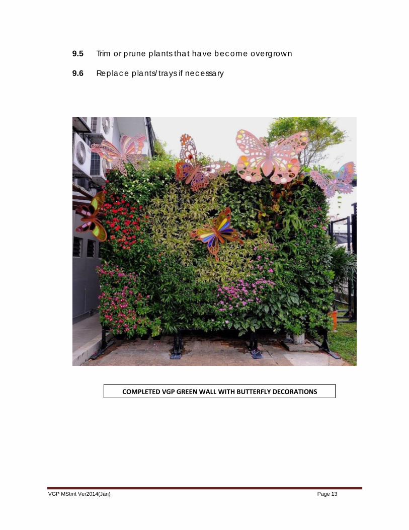
COMPLETED VGP GREEN WALL WITH BUTTERFLY DECORATIONS