Embed Size (px)
DESCRIPTION
Metallographic Handbook
Citation preview
1
2
Copyright 2010by
PACE Technologies
No part of this manual may be reproduced, stored in a retrieval system, or transmitted, inany form or by any means, electronic, mechanical, photocopying, recording, or otherwise,without the written permission of the copyright owner.
First printing, 2010
Great care is taken in the compilation and production of this book, but it should be madeclear that NO WARRANTIES, EXPRESS OR IMPLIED, INCLUDING, WITHOUTLIMITATION, WARRANTIES OF MERCHANTABILITY OR FITNESS FOR APARTICULAR PURPOSE, ARE GIVEN IN CONNECTION WITH THISPUBLICATION. Although this information is believed to be accurate by PACETechnologies, PACE Technologies cannot guarantee that favorable results will beobtained from the use of this publication alone. This publication is intended for use bypersons having technical skill, at their sole discretion and risk. Since the conditions ofproduct or material use are outside of PACE Technologies control, PACE Technologiesassumes no liability or obligation in connection with any use of this information. Noclaim of any kind, whether as to products or information in this publication, and whetheror not based on negligence, shall be greater in amount than the purchase price of thisproduct or publication in respect of which damages are claimed. THE REMEDYHEREBY PROVIDED SHALL BE THE EXCLUSIVE AND SOLE REMEDY ORBUYER, AND IN NO EVENT SHALL EITHER PARTY BE LIABLE FOR SPECIAL,INDIRECT OR CONSEQUENTIAL DAMAGES WHETHER OR NOT CAUSED BYOR RESULTING FROM THE NEGLIGENCE OF SUCH PARTY. As with any material,evaluation of the material under end use conditions prior to specifications is essential.Therefore, specific testing under actual conditions is recommended.
Nothing contained in this book shall be construed as a grant of any right of manufacture,sale, use, or reproduction in connection with any method, process, apparatus, product,composition, or system, whether or not covered by letter paten, copyright, or trademark,and noting contained in this book shall be construed as a defense against any allegedinfringement of letters paten, copyright, or trademark, or as a defense against liability forsuch infringement.
Comments, criticism, and suggestions are invited, and should be forwarded to PACETechnologies staff who worked on this project included Don Zipperian, Vice President ofTechnology.
PACE Technologies3601 E. 34th St.
Tucson, AZ
Printed in China
3
Table of ContentsCHAPTER 1
Introduction to Metallography ................................................................ 9Grain Size ......................................................................................................... 10Twin Boundaries .............................................................................................. 10Porosity and Voids ........................................................................................... 11Cracks .............................................................................................................. 11Phases .............................................................................................................. 12Dendrites .......................................................................................................... 13Corrosion ......................................................................................................... 13Intergranular Attack ........................................................................................ 14Coating Thickness ........................................................................................... 15Inclusions ......................................................................................................... 16Weld Analysis ................................................................................................... 17Solder Joint Integrity ....................................................................................... 19Composites ....................................................................................................... 19Graphite Nodularity ......................................................................................... 20Recast ............................................................................................................... 21Carburizing ...................................................................................................... 22Decarburization ............................................................................................... 23Nitriding ........................................................................................................... 23Intergranular Fracture ................................................................................... 24Weld Sensitization ............................................................................................ 24Flow Line Stress .............................................................................................. 25
CHAPTER 2Abrasive Sectioning ................................................................................ 26
2.0 ABRASIVE SECTIONING ..................................................................... 262.1 ABRASIVE BLADE SELECTION GUIDELINES .............................. 272.2 ABRASIVE CUTTING PROCESS DESCRIPTION ............................ 292.3 RECOMMENDED CUTTING PROCEDURES ................................... 302.4 CUTTING FLUIDS .................................................................................. 302.5 ABRASIVE SECTIONING TROUBLESHOOTING ........................... 31
CHAPTER 3Precision Wafer Sectioning .................................................................... 32
4
3.0 PRECISION WAFER SECTIONING .................................................... 323.1 WAFERING BLADE CHARACTERISTICS........................................ 333.2 CUTTING PARAMETERS ..................................................................... 39
CHAPTER 4Specimen Mounting ................................................................................ 41
4.0 SPECIMEN MOUNTING ...................................................................... 414.1 CASTABLE MOUNTING ..................................................................... 414.1.2 Acrylic Castable Resins ......................................................................... 444.1.3 Polyester Castable Resins ...................................................................... 464.2 CASTABLE MOUNTING PROCEDURES ......................................... 474.2.1 Vacuum/Pressure Mounting ................................................................. 484.3 CASTABLE MOUNTING MISCELLANEOUS .................................. 494.4 CASTABLE MOUNTING TROUBLESHOOTING ............................ 514.5 COMPRESSION MOUNTING ............................................................. 524.6 COMPRESSION MOUNTING RESIN PROPERTIES ...................... 554.6.1 Phenolics ................................................................................................ 584.6.2 Acrylics ................................................................................................... 584.6.3 Epoxies / Diallyl Phthalates .................................................................. 604.6.4 Specialized Compression Mounting Resins ......................................... 614.7 COMPRESSION MOUNTING PROCEDURES ................................. 614.8 COMPRESSION MOUNTING TROUBLESHOOTING ................... 62
CHAPTER 5Abrasive Grinding .................................................................................. 63
5.0 ABRASIVE GRINDING ......................................................................... 635.1.1 Silicon Carbide ....................................................................................... 645.1.2 Alumina ................................................................................................... 715.1.3 Diamond .................................................................................................. 715.1.4 Zircon ...................................................................................................... 755.2 ABRASIVE BONDING .......................................................................... 755.2.1 Fixed Abrasive Grinding ........................................................................ 755.2.2 Free Abrasive Grinding .......................................................................... 765.2.3 Semi-fixed Abrasive Grinding ................................................................ 765.3 ROUGH GRINDING PARAMETERS ................................................. 785.3.1 Grinding Pressure .................................................................................. 785.3.2 Relative Velocity ...................................................................................... 795.4 PLANAR GRINDING (ROUGH GRINDING) .................................... 835.4.1 Soft Nonferrous Metals .......................................................................... 835.4.2 Soft Ferrous Metals ................................................................................ 83
5
5.4.3 Hard Ferrous Metals .............................................................................. 835.4.4 Super Alloys and Hard Nonferrous Alloys ............................................ 835.4.5 Ceramics ................................................................................................. 845.4.6 Composites .............................................................................................. 845.5 PLANAR GRINDING TROUBLESHOOTING .................................. 845.6 PRECISION GRINDING WITH LAPPING FILMS .......................... 855.6.1 Diamond Lapping Films ........................................................................ 855.6.2 Silicon Carbide Lapping Films .............................................................. 865.6.3 Alumina Lapping Films ......................................................................... 875.7 LAPPING FILM TROUBLESHOOTING ........................................... 885.8 ROUGH POLISHING ............................................................................ 885.8.1 Rough Polishing Abrasives .................................................................... 895.8.2 Rough Polishing Pads ............................................................................ 895.8.3 Rough Polish Lapping Films ................................................................. 915.8.4 Automated Rough Polishing .................................................................. 925.8.5 CMP (Chemical Mechanical Polishing) ................................................ 92
CHAPTER 6Final Polishing ........................................................................................ 97
6.0 FINAL POLISHING ............................................................................... 976.1 FINAL POLISHING ABRASIVES........................................................ 986.1.1 Polycrystalline Alumina ......................................................................... 986.1.2 Calcined Alumina Polishing Abrasives ............................................... 1036.1.3 Colloidal Silica Polishing Abrasives .................................................... 1046.2 ALTERNATIVE POLISHING TECHNIQUES ................................. 1076.2.1 Electrolytic Polishing ........................................................................... 1076.2.2 Attack polishing .................................................................................... 1076.2.3 Vibratory polishing ............................................................................... 1086.3 FINAL POLISHING TROUBLESHOOTING ................................... 1106.3.1 Scratches ............................................................................................... 1126.3.2 Smearing ............................................................................................... 1136.3.3 Recrystallization ................................................................................... 1146.3.4 Comet Tails ........................................................................................... 1156.3.5 Embedded Abrasives ............................................................................. 1166.3.6 Edge Rounding ..................................................................................... 1176.3.7 Polishing Relief ................................................................................... 1186.3.8 Pull-out ................................................................................................ 1196.3.9 Gaps and Staining ................................................................................. 120
6
6.3.10 Porosity and cracks ............................................................................ 121
CHAPTER 7Electrolytic Polishing ............................................................................ 122
7.0 ELECTROLYTIC POLISHING ......................................................... 1227.1 SPECIMEN PREPARATION .............................................................. 1227.2 SAFETY PRECAUTIONS ................................................................... 1237.2.1 Perchloric Acid (HClO4) Electrolyte Precautions .............................. 1237.3 ELECTROLYTIC EQUIPMENT ....................................................... 1247.4 ELECTROLYTE SOLUTIONS ........................................................... 125
CHAPTER 8Metallographic Etching ....................................................................... 132
8.0 ETCHING .............................................................................................. 1328.1 CHEMICAL ETCHING ....................................................................... 1338.2 ELECTROLYTIC ETCHING ............................................................. 1338.3 MOLTEN SALT ETCHING ................................................................. 1348.4 THERMAL ETCHING ......................................................................... 134
CHAPTER 9Microscopy and Image Analysis .......................................................... 136
9.0 MICROSCOPY ..................................................................................... 1369.0.1 Definitions ............................................................................................. 1379.0.2 Resolution and Numerical Aperture (N.A.) ......................................... 1379.0.3 Optical Filters ....................................................................................... 1389.1 BRIGHTFIELD ..................................................................................... 1389.2 DARKFIELD ......................................................................................... 1399.3 DIFFERENTIAL INTERFERENCE CONTRAST ........................... 1409.4 METALLOGRAPHIC IMAGE ANALYSIS ...................................... 1409.4.1 Grain size (ASTM E112, E930, E1181) .............................................. 1419.4.2 Phase Analysis (ASTM E566, 1245) ................................................... 1439.4.3 Nodularity (ASTM A247) ..................................................................... 1459.4.4 Porosity (ASTM 276) ........................................................................... 1509.4.5 Inclusion rating (ASTM E454) ........................................................... 1529.4.6 Decarburization (ASTM E1077) ......................................................... 1539.4.7 Coating thickness (ASTM B487) ........................................................ 1559.4.8 Weld analysis ........................................................................................ 157
CHAPTER 10Hardness Testing ................................................................................... 159
7
10.0 HARDNESS ......................................................................................... 15910.1 ROCKWELL HARDNESS ................................................................ 16110.2 BRINELL HARDNESS ...................................................................... 16110.3 VICKERS HARDNESS ...................................................................... 16110.4 MICROHARDNESS ........................................................................... 162
CHAPTER 11Metallographic Specimen Preparation ............................................... 164
11.0 PROCEDURES / ETCHANTS .......................................................... 16411.1 CLASS 1 - DUCTILE MATERIALS ................................................. 16811.1.1 Aluminum and Aluminum Alloys ...................................................... 16911.1.2 Copper ................................................................................................. 17311.1.3 Brass .................................................................................................... 17911.1.4 Bronze ................................................................................................. 18111.1.5 Tin and Tin Alloys ............................................................................... 18311.1.6 Lead and Lead Alloys ......................................................................... 18711.1.7 Zinc and Zinc Alloys ........................................................................... 19011.1.8 Carbon-Carbon PMC Composites ..................................................... 19411.2 CLASS 2 - VERY SOFT, LOW DUCTILITY MATERIALS.......... 19711.2.1 Refractory Materials (Rhenium, Niobium, Tungsten) ...................... 19811.2.2 Rare Earth - Neodymium ................................................................... 20211.2.3 Tungsten .............................................................................................. 20511.2.4 Precious Metals (Gold, Silver, Platinum) .......................................... 20811.3 CLASS 3 - LOWER DUCTILITY METALS ................................... 21211.3.1 Sintered Iron - Powder Metallurgy .................................................... 21311.3.2 Cast Irons ............................................................................................ 21411.3.3 White Irons .......................................................................................... 21711.4 CLASS 4 - SOFT, BRITTLE NONMETALS (Electronics) ............. 22211.4.1 Multilayer Ceramic Capacitors .......................................................... 22211.4.2 Electronic Die Packages (Silicon, Plastic, Solder Joints, Ceramics) 22511.4.3 MEMS (Microelectromechanical System) Devices ........................... 22811.4.4 PZT (piezoelectric) Devices ................................................................ 23011.4.5 Electronic Metallized Ceramics (Alumina, BeO, AlN) ..................... 23211.4.6 Magnetic Ceramics (Ferrite) .............................................................. 23411.5 CLASS 5 - MEDIUM HARD, DUCTILE METALS ........................ 23811.5.1 Soft to Medium Hard Steels ................................................................ 23911.5.2 Stainless Steel ...................................................................................... 24411.6 CLASS 6 - TOUGH, HARD NON-FERROUS METALS ............... 24811.6.1 Superalloys .......................................................................................... 24911.6.2 Titanium and Titanium Alloys (Conventional Polishing) ................. 256
8
11.6.3 Titanium Alloy - Attack Polishing ...................................................... 25911.7 CLASS 7 - THERMAL SPRAY MATERIALS ................................. 26411.7.1 Thermal Spray Coatings ..................................................................... 26611.8 CLASS 8 - HARDENED STEELS ..................................................... 26811.8.1 Tool Steels ............................................................................................ 26911.8.2 Nitrided Steel ....................................................................................... 27111.9 CLASS 9 - METAL MATRIX COMPOSITES ................................. 27511.9.1 Metal Matrix Composites ................................................................... 27611.9.2 Metal Matrix Composite - Metal Injection Molding (MIM) ............. 27911.10 CLASS 10 - ENGINEERED CERAMICS ...................................... 28111.10.1 Engineered Ceramics - ZrO2, SiALON, Si3N4 ............................... 28211.10.2 Engineered Ceramics - Alumina ...................................................... 28411.10.3 Engineered Ceramics - ALON ......................................................... 28611.10.4 Engineered Ceramics - SiSiC .......................................................... 289
Index .............................................................................................................. 294
9
CHAPTER 1Introduction to Metallography
Metallography has been described as both a science and an art. Traditionally,metallography has been the study of the microscopic structure of metals andalloys using optical metallographs, electron microscopes or other surfaceanalysis equipment. More recently, as materials have evolved, metallographyhas expanded to incorporate materials ranging from electronics to sportinggood composites. By analyzing a material’s microstructure, its performanceand reliability can be better understood. Thus metallography is used inmaterials development, incoming inspection, production and manufacturingcontrol, and for failure analysis; in other words, product reliability.
Metallography or microstructural analysis includes, but is not limited to, thefollowing types of analysis:
• Grain size• Porosity and voids• Phase analysis• Dendritic growth• Cracks and other defects• Corrosion analysis• Intergranular attack (IGA)• Coating thickness and integrity• Inclusion size, shape and distribution• Weld and heat-affected zones (HAZ)• Distribution and orientation of composite fillers• Graphite nodularity• Recast• Carburizing thickness• Decarburization• Nitriding thickness• Intergranular fracturing• HAZ Sensitization• Flow-line Stress
10
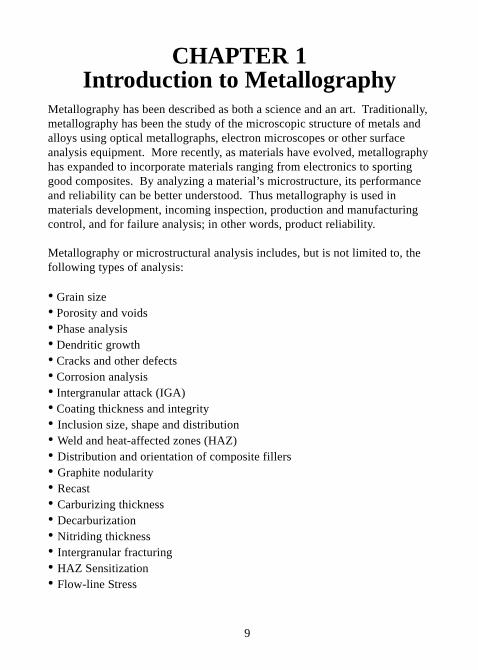
Grain Size
For metals and ceramics, grain size is perhaps the most significantmetallographic measurement because it can be directly related to themechanical properties of the material. Although grain size is actually a 3-dimensional property, it is measured from a 2-dimensional cross section of thematerial. Common grain size measurements include grains per unit area/volume, average diameter or grain size number. Determination of the grainsize number can be calculated or compared to standardized grain size charts.Modern image analysis algorithms are very useful for determining grain size.
Figure 1-1 Grain size- anodized aluminum. Figure 1-2 Rhenium grain size.(photo courtesy of Clemex Technologies)
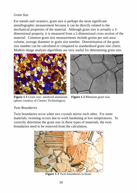
Twin Boundaries
Twin boundaries occur when two crystals mirror each other. For somematerials, twinning occurs due to work hardening at low temperatures. Tocorrectly determine the grain size in these types of materials, the twinboundaries need to be removed from the calculation.
Figure 1-3 Twin boundaries in brass.
11
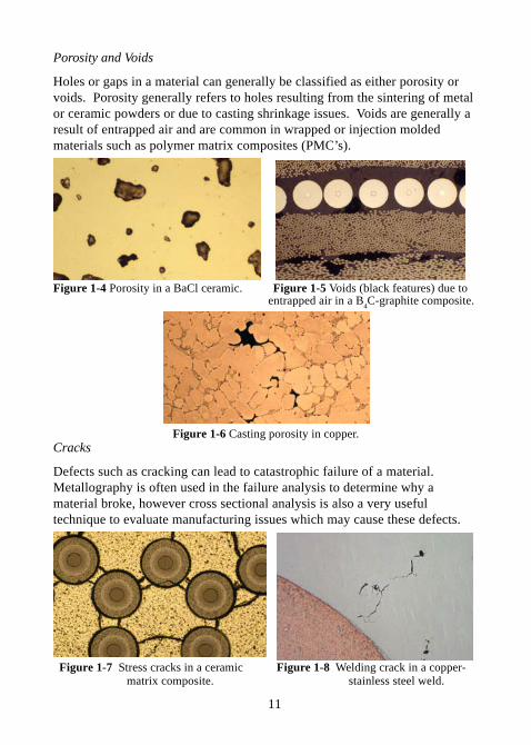
Porosity and Voids
Holes or gaps in a material can generally be classified as either porosity orvoids. Porosity generally refers to holes resulting from the sintering of metalor ceramic powders or due to casting shrinkage issues. Voids are generally aresult of entrapped air and are common in wrapped or injection moldedmaterials such as polymer matrix composites (PMC’s).
Figure 1-4 Porosity in a BaCl ceramic. Figure 1-5 Voids (black features) due to entrapped air in a B
4C-graphite composite.
Figure 1-6 Casting porosity in copper.Cracks
Defects such as cracking can lead to catastrophic failure of a material.Metallography is often used in the failure analysis to determine why amaterial broke, however cross sectional analysis is also a very usefultechnique to evaluate manufacturing issues which may cause these defects.
Figure 1-7 Stress cracks in a ceramic Figure 1-8 Welding crack in a copper- matrix composite. stainless steel weld.
12
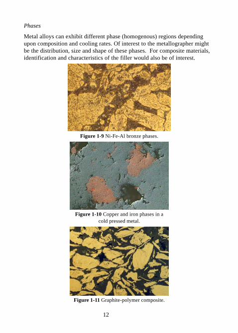
Phases
Metal alloys can exhibit different phase (homogenous) regions dependingupon composition and cooling rates. Of interest to the metallographer mightbe the distribution, size and shape of these phases. For composite materials,identification and characteristics of the filler would also be of interest.
Figure 1-9 Ni-Fe-Al bronze phases.
Figure 1-10 Copper and iron phases in acold pressed metal.
Figure 1-11 Graphite-polymer composite.
13
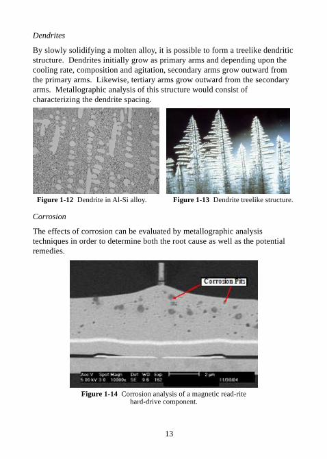
Dendrites
By slowly solidifying a molten alloy, it is possible to form a treelike dendriticstructure. Dendrites initially grow as primary arms and depending upon thecooling rate, composition and agitation, secondary arms grow outward fromthe primary arms. Likewise, tertiary arms grow outward from the secondaryarms. Metallographic analysis of this structure would consist ofcharacterizing the dendrite spacing.
Figure 1-12 Dendrite in Al-Si alloy. Figure 1-13 Dendrite treelike structure.
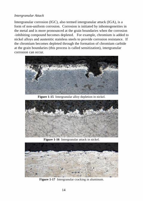
Corrosion
The effects of corrosion can be evaluated by metallographic analysistechniques in order to determine both the root cause as well as the potentialremedies.
Figure 1-14 Corrosion analysis of a magnetic read-ritehard-drive component.
14
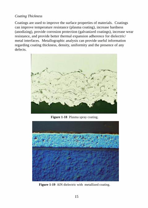
Intergranular Attack
Intergranular corrosion (IGC), also termed intergranular attack (IGA), is aform of non-uniform corrosion. Corrosion is initiated by inhomogeneities inthe metal and is more pronounced at the grain boundaries when the corrosion-inhibiting compound becomes depleted. For example, chromium is added tonickel alloys and austenitic stainless steels to provide corrosion resistance. Ifthe chromium becomes depleted through the formation of chromium carbideat the grain boundaries (this process is called sensitization), intergranularcorrosion can occur.
Figure 1-15 Intergranular alloy depletion in nickel.
Figure 1-16 Intergranular attack in nickel.
Figure 1-17 Intergranular cracking in aluminum.
15
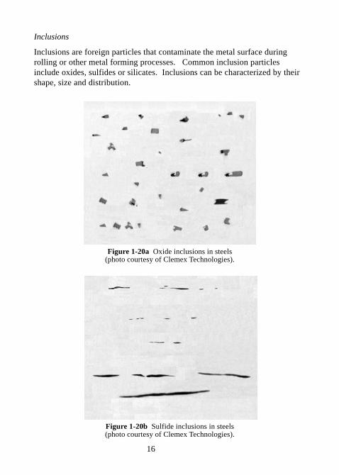
Coating Thickness
Coatings are used to improve the surface properties of materials. Coatingscan improve temperature resistance (plasma coating), increase hardness(anodizing), provide corrosion protection (galvanized coatings), increase wearresistance, and provide better thermal expansion adherence for dielectric/metal interfaces. Metallographic analysis can provide useful informationregarding coating thickness, density, uniformity and the presence of anydefects.
Figure 1-18 Plasma spray coating.
Figure 1-19 AlN dielectric with metallized coating.
16
Inclusions
Inclusions are foreign particles that contaminate the metal surface duringrolling or other metal forming processes. Common inclusion particlesinclude oxides, sulfides or silicates. Inclusions can be characterized by theirshape, size and distribution.
Figure 1-20a Oxide inclusions in steels(photo courtesy of Clemex Technologies).
Figure 1-20b Sulfide inclusions in steels(photo courtesy of Clemex Technologies).
17
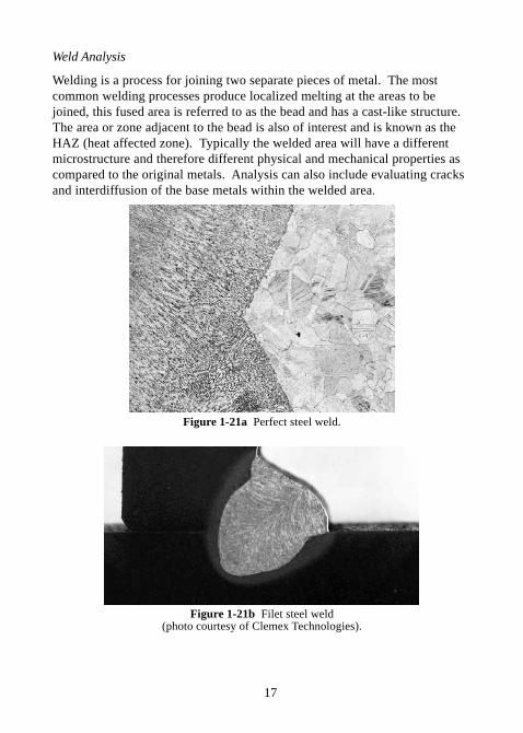
Weld Analysis
Welding is a process for joining two separate pieces of metal. The mostcommon welding processes produce localized melting at the areas to bejoined, this fused area is referred to as the bead and has a cast-like structure.The area or zone adjacent to the bead is also of interest and is known as theHAZ (heat affected zone). Typically the welded area will have a differentmicrostructure and therefore different physical and mechanical properties ascompared to the original metals. Analysis can also include evaluating cracksand interdiffusion of the base metals within the welded area.
Figure 1-21a Perfect steel weld.
Figure 1-21b Filet steel weld(photo courtesy of Clemex Technologies).
18
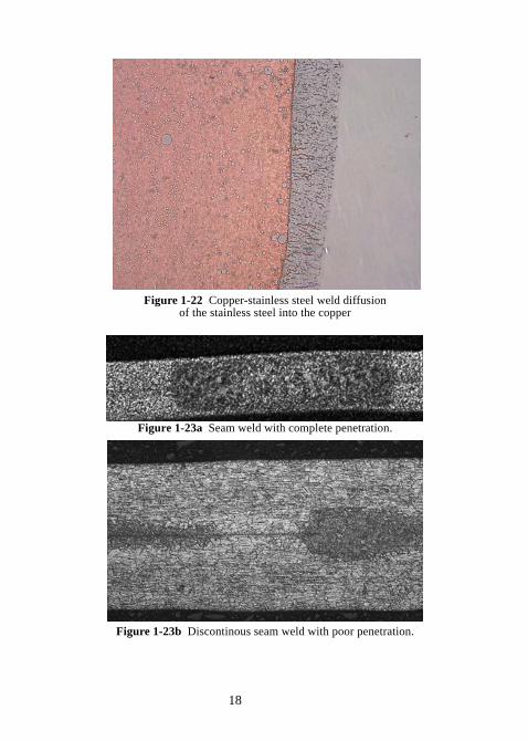
Figure 1-22 Copper-stainless steel weld diffusionof the stainless steel into the copper
Figure 1-23a Seam weld with complete penetration.
Figure 1-23b Discontinous seam weld with poor penetration.
19
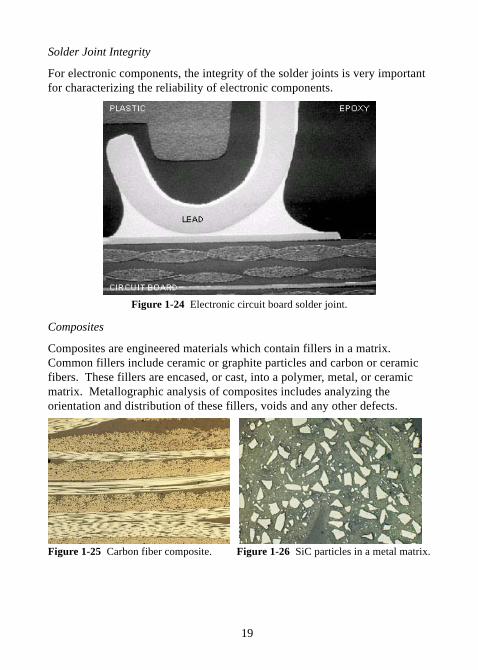
Solder Joint Integrity
For electronic components, the integrity of the solder joints is very importantfor characterizing the reliability of electronic components.
Figure 1-24 Electronic circuit board solder joint.
Composites
Composites are engineered materials which contain fillers in a matrix.Common fillers include ceramic or graphite particles and carbon or ceramicfibers. These fillers are encased, or cast, into a polymer, metal, or ceramicmatrix. Metallographic analysis of composites includes analyzing theorientation and distribution of these fillers, voids and any other defects.
Figure 1-25 Carbon fiber composite. Figure 1-26 SiC particles in a metal matrix.
20
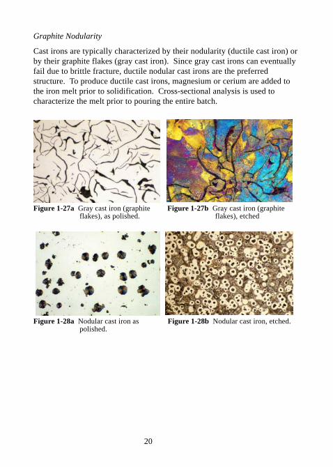
Graphite Nodularity
Cast irons are typically characterized by their nodularity (ductile cast iron) orby their graphite flakes (gray cast iron). Since gray cast irons can eventuallyfail due to brittle fracture, ductile nodular cast irons are the preferredstructure. To produce ductile cast irons, magnesium or cerium are added tothe iron melt prior to solidification. Cross-sectional analysis is used tocharacterize the melt prior to pouring the entire batch.
Figure 1-27a Gray cast iron (graphite Figure 1-27b Gray cast iron (graphite flakes), as polished. flakes), etched
Figure 1-28a Nodular cast iron as Figure 1-28b Nodular cast iron, etched. polished.
21
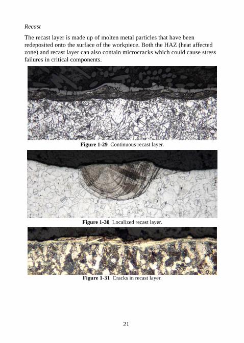
Recast
The recast layer is made up of molten metal particles that have beenredeposited onto the surface of the workpiece. Both the HAZ (heat affectedzone) and recast layer can also contain microcracks which could cause stressfailures in critical components.
Figure 1-29 Continuous recast layer.
Figure 1-30 Localized recast layer.
Figure 1-31 Cracks in recast layer.
22
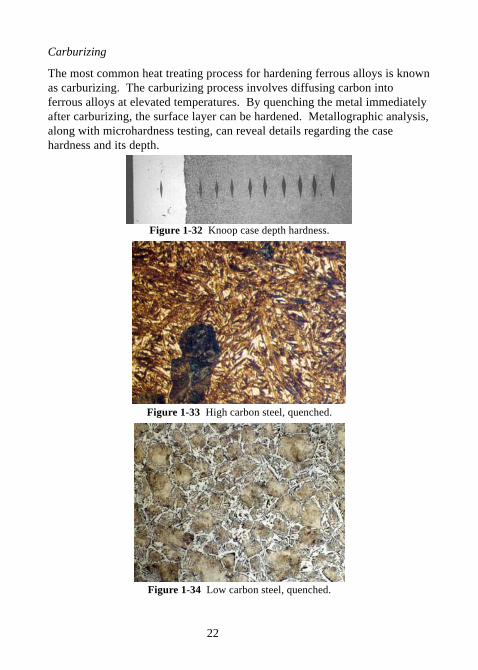
Carburizing
The most common heat treating process for hardening ferrous alloys is knownas carburizing. The carburizing process involves diffusing carbon intoferrous alloys at elevated temperatures. By quenching the metal immediatelyafter carburizing, the surface layer can be hardened. Metallographic analysis,along with microhardness testing, can reveal details regarding the casehardness and its depth.
Figure 1-32 Knoop case depth hardness.
Figure 1-33 High carbon steel, quenched.
Figure 1-34 Low carbon steel, quenched.
23
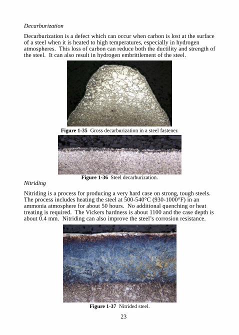
Decarburization
Decarburization is a defect which can occur when carbon is lost at the surfaceof a steel when it is heated to high temperatures, especially in hydrogenatmospheres. This loss of carbon can reduce both the ductility and strength ofthe steel. It can also result in hydrogen embrittlement of the steel.
Figure 1-35 Gross decarburization in a steel fastener.
Figure 1-36 Steel decarburization.Nitriding
Nitriding is a process for producing a very hard case on strong, tough steels.The process includes heating the steel at 500-540°C (930-1000°F) in anammonia atmosphere for about 50 hours. No additional quenching or heattreating is required. The Vickers hardness is about 1100 and the case depth isabout 0.4 mm. Nitriding can also improve the steel’s corrosion resistance.
Figure 1-37 Nitrided steel.
24
Intergranular Fracture
Intergranular cracking or fracturing is a fracture that occurs along the grainboundaries of a material. An intergranular fracture can result from improperheat treating, inclusions or second-phase particles located at grain boundaries,and high cyclic loading.
Figure 1-38 Intergranular fracturing forimproperly heat treated 17-7PH, 1000X.
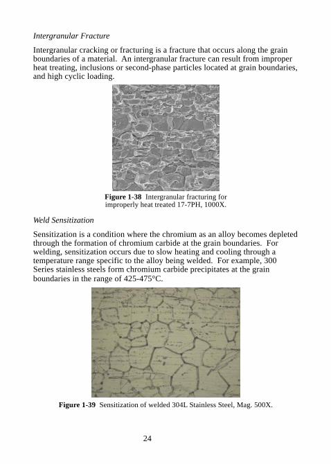
Weld Sensitization
Sensitization is a condition where the chromium as an alloy becomes depletedthrough the formation of chromium carbide at the grain boundaries. Forwelding, sensitization occurs due to slow heating and cooling through atemperature range specific to the alloy being welded. For example, 300Series stainless steels form chromium carbide precipitates at the grainboundaries in the range of 425-475°C.
Figure 1-39 Sensitization of welded 304L Stainless Steel, Mag. 500X.
25
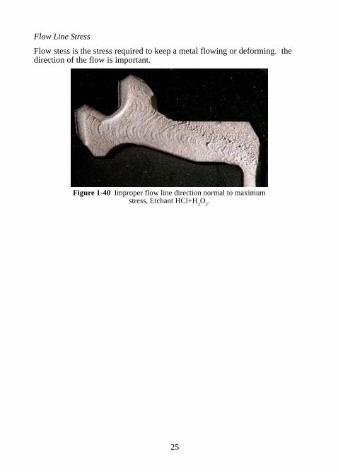
Flow Line Stress
Flow stess is the stress required to keep a metal flowing or deforming. thedirection of the flow is important.
Figure 1-40 Improper flow line direction normal to maximumstress, Etchant HCl+H
2O
2.
26
CHAPTER 2Abrasive Sectioning
2.0 ABRASIVE SECTIONING
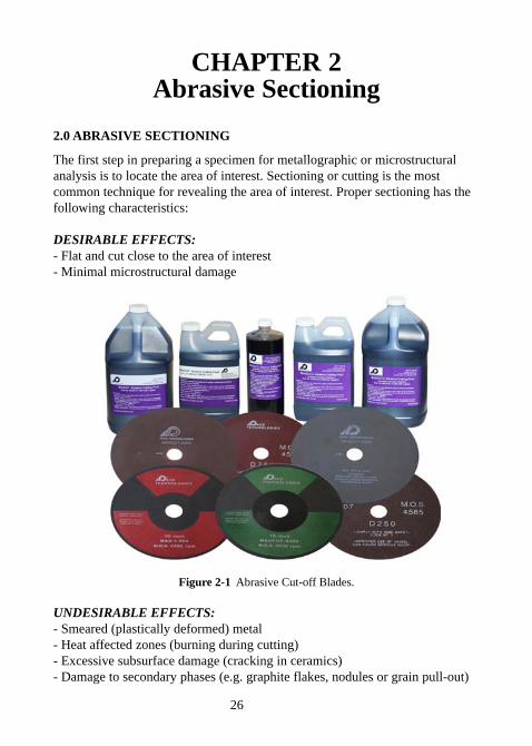
The first step in preparing a specimen for metallographic or microstructuralanalysis is to locate the area of interest. Sectioning or cutting is the mostcommon technique for revealing the area of interest. Proper sectioning has thefollowing characteristics:
DESIRABLE EFFECTS:- Flat and cut close to the area of interest- Minimal microstructural damage
Figure 2-1 Abrasive Cut-off Blades.
UNDESIRABLE EFFECTS:- Smeared (plastically deformed) metal- Heat affected zones (burning during cutting)- Excessive subsurface damage (cracking in ceramics)- Damage to secondary phases (e.g. graphite flakes, nodules or grain pull-out)
27
The goal of any cutting operation is to maximize the desirable effects, whileminimizing the undesirable effects.
Sectioning can be categorized as either abrasive cutting and precision wafercutting. abrasive cutting is generally used for metal specimens and isaccomplished with silicon carbide or alumina abrasives in either a resin orresin-rubber bond. Proper blade selection is required to minimize burning andheat generation during cutting, which degrades both the specimen surface aswell as the abrasive blades cutting efficiency. Wafer cutting is achieved withvery thin precision blades. The most common wafering blades are rim-pressedabrasive blades, in which the abrasive is located along the edge or rim of theblade. Precision wafering blades most commonly use diamond abrasives,however cubic boron nitride (CBN) is also used for cutting samples that reactto dull diamond (e.g. high carbon, heat treated steels cut more effectively withCBN as compared to diamond). Wafer cutting is especially useful for cuttingelectronic materials, ceramics and minerals, bone, composites and even somemetallic materials.
2.1 ABRASIVE BLADE SELECTION GUIDELINES
Selecting the correct abrasive blade is dependent upon the design of the cut-offmachine and, to a large extent, the operator preference. Abrasive blades aregenerally characterized by their abrasive type, bond type and hardness.Determining the correct blade is dependent upon the material or metal hardnessand whether it is a ferrous or a nonferrous metal. In practice, it often comesdown to odor and blade life. Resin/rubber blades smell more because therubber will burn slightly during cutting, however resin/rubber blades do notwear as fast and therefore last longer. On the other hand, resin blades are moreversatile and do not produce a burnt rubber odor, but they do break downfaster. Resin blades also provide a modestly better cut because the cuttingabrasive is continually renewed and thus produces a cleaner cut.
Also note that the traditional “older” technology for producing abrasive bladesresulted in very specialized resin/rubber blades. Finding the proper resin/rubber hardness, abrasive size, and blade thickness to match the sampleproperties and the cutting machine parameter required a lot of testing andexperimentation. Thus, in the past, resin/rubber blades had been more popularin the US market; however, in more recent years as resins have improved, therehas been more of a trend towards resin bonded abrasives. Conversely, resinbonded blades have typically been more widely used in the European and
28
Asian markets for quite some time.
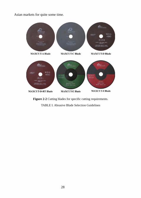
Figure 2-2 Cutting blades for specific cutting requirements.
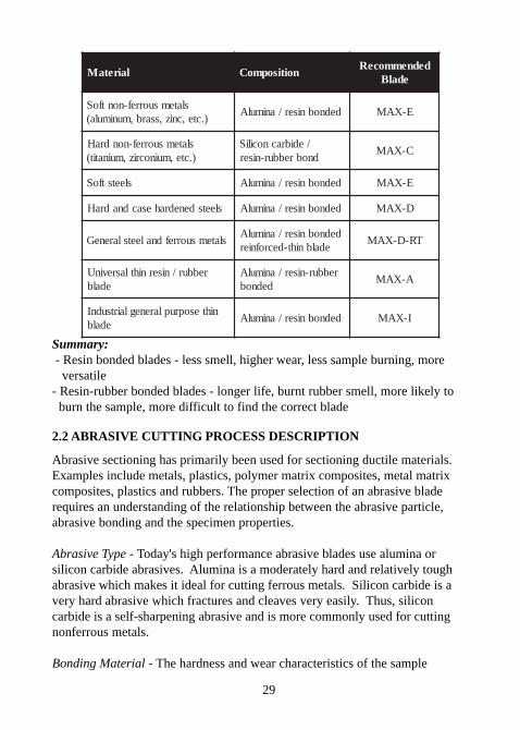
TABLE I. Abrasive Blade Selection Guidelines
29
lairetaM noitisopmoCdednemmoceR
edalB
slatemsuorref-nontfoS).cte,cniz,ssarb,munimula(
dednobniser/animulA E-XAM
slatemsuorref-nondraH).cte,muinocriz,muinatit(
/edibracnociliSdnobrebbur-niser
C-XAM
sleetstfoS dednobniser/animulA E-XAM
sleetsdenedrahesacdnadraH dednobniser/animulA D-XAM
slatemsuorrefdnaleetslareneGdednobniser/animulA
edalbniht-decrofnierTR-D-XAM
rebbur/nisernihtlasrevinUedalb
rebbur-niser/animulAdednob
A-XAM
nihtesopruplareneglairtsudnIedalb
dednobniser/animulA I-XAM
Summary: - Resin bonded blades - less smell, higher wear, less sample burning, more versatile- Resin-rubber bonded blades - longer life, burnt rubber smell, more likely to burn the sample, more difficult to find the correct blade
2.2 ABRASIVE CUTTING PROCESS DESCRIPTION
Abrasive sectioning has primarily been used for sectioning ductile materials.Examples include metals, plastics, polymer matrix composites, metal matrixcomposites, plastics and rubbers. The proper selection of an abrasive bladerequires an understanding of the relationship between the abrasive particle,abrasive bonding and the specimen properties.
Abrasive Type - Today's high performance abrasive blades use alumina orsilicon carbide abrasives. Alumina is a moderately hard and relatively toughabrasive which makes it ideal for cutting ferrous metals. Silicon carbide is avery hard abrasive which fractures and cleaves very easily. Thus, siliconcarbide is a self-sharpening abrasive and is more commonly used for cuttingnonferrous metals.
Bonding Material - The hardness and wear characteristics of the sample
30
determine which resin system is the best-suited for abrasive cutting. Ingeneral, the optimum bonding material is one that breaks down at the same rateas the abrasive dulls; thus, exposing new abrasives for the most efficient andeffective cutting operation.
2.3 RECOMMENDED CUTTING PROCEDURES
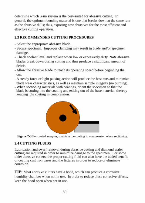
- Select the appropriate abrasive blade.- Secure specimen. Improper clamping may result in blade and/or specimen damage.- Check coolant level and replace when low or excessively dirty. Note abrasive blades break down during cutting and thus produce a significant amount of debris.- Allow the abrasive blade to reach its operating speed before beginning the cut.- A steady force or light pulsing action will produce the best cuts and minimize blade wear characteristics, as well as maintain sample integrity (no burning).- When sectioning materials with coatings, orient the specimen so that the blade is cutting into the coating and exiting out of the base material, thereby keeping the coating in compression.
Figure 2-3 For coated samples, maintain the coating in compression when sectioning.
2.4 CUTTING FLUIDS
Lubrication and swarf removal during abrasive cutting and diamond wafercutting are required in order to minimize damage to the specimen. For someolder abrasive cutters, the proper cutting fluid can also have the added benefitof coating cast iron bases and the fixtures in order to reduce or eliminatecorrosion.
TIP: Most abrasive cutters have a hood, which can produce a corrosivehumidity chamber when not in use. In order to reduce these corrosive effects,keep the hood open when not in use.
31
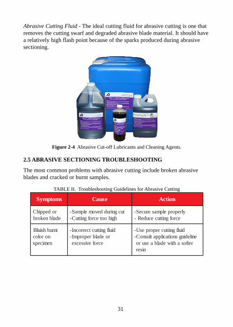
Abrasive Cutting Fluid - The ideal cutting fluid for abrasive cutting is one thatremoves the cutting swarf and degraded abrasive blade material. It should havea relatively high flash point because of the sparks produced during abrasivesectioning.
Figure 2-4 Abrasive Cut-off Lubricants and Cleaning Agents.
2.5 ABRASIVE SECTIONING TROUBLESHOOTING
The most common problems with abrasive cutting include broken abrasiveblades and cracked or burnt samples.
TABLE II. Troubleshooting Guidelines for Abrasive Cutting
smotpmyS esuaC noitcA
rodeppihCedalbnekorb
tucgniruddevomelpmaS-hgihootecrofgnittuC-
ylreporpelpmaseruceS-ecrofgnittucecudeR-
tnrubhsiulBnorolocnemiceps
diulfgnittuctcerrocnI-roedalbreporpmI-
ecrofevissecxe
diulfgnittucreporpesU-enilediugsnoitacilppatlusnoC-
retfosahtiwedalbaesuroniser
32
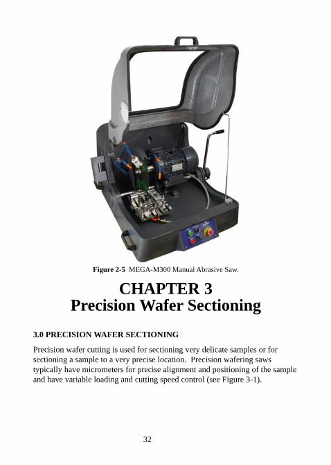
Figure 2-5 MEGA-M300 Manual Abrasive Saw.
CHAPTER 3Precision Wafer Sectioning
3.0 PRECISION WAFER SECTIONING
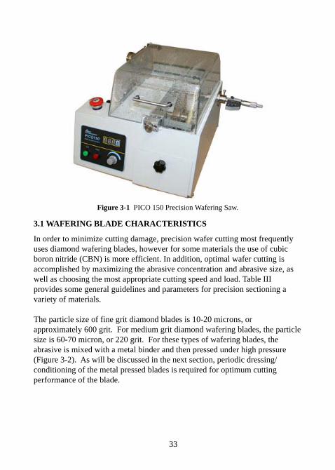
Precision wafer cutting is used for sectioning very delicate samples or forsectioning a sample to a very precise location. Precision wafering sawstypically have micrometers for precise alignment and positioning of the sampleand have variable loading and cutting speed control (see Figure 3-1).
33
Figure 3-1 PICO 150 Precision Wafering Saw.
3.1 WAFERING BLADE CHARACTERISTICS
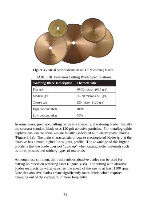
In order to minimize cutting damage, precision wafer cutting most frequentlyuses diamond wafering blades, however for some materials the use of cubicboron nitride (CBN) is more efficient. In addition, optimal wafer cutting isaccomplished by maximizing the abrasive concentration and abrasive size, aswell as choosing the most appropriate cutting speed and load. Table IIIprovides some general guidelines and parameters for precision sectioning avariety of materials.
The particle size of fine grit diamond blades is 10-20 microns, orapproximately 600 grit. For medium grit diamond wafering blades, the particlesize is 60-70 micron, or 220 grit. For these types of wafering blades, theabrasive is mixed with a metal binder and then pressed under high pressure(Figure 3-2). As will be discussed in the next section, periodic dressing/conditioning of the metal pressed blades is required for optimum cuttingperformance of the blade.
34
Figure 3-2 Metal pressed diamond and CBN wafering blades.
TABLE III. Precision Cutting Blade Specifications
noitpircseDedalBgnirefaW citsiretcarahC
tirgeniF )tirg006(norcim02-01
tirgmuideM )tirg022(norcim07-06
tirgesraoC )tirg021(norcim021
noitartnecnochgiH %001
noitartnecnocwoL %05
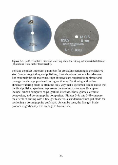
In some cases, precision cutting requires a coarser grit wafering blade. Usuallythe coarsest standard blade uses 120 grit abrasive particles. For metallographicapplications, coarse abrasives are mostly associated with electroplated blades(Figure 3-3a). The main characteristic of coarse electroplated blades is that theabrasive has a much higher, or rougher, profile. The advantage of this higherprofile is that the blade does not “gum up” when cutting softer materials suchas bone, plastics and rubbery types of materials.
Although less common, thin resin-rubber abrasive blades can be used forcutting on precision wafering saws (Figure 3-3b). For cutting with abrasiveblades on precision wafer saws, set the speed of the saw to at least 1500 rpm.Note that abrasive blades create significantly more debris which requireschanging out of the cutting fluid more frequently.
35
Figure 3-3 (a) Electroplated diamond wafering blade for cutting soft materials (left) and(b) alumina resin-rubber blade (right).
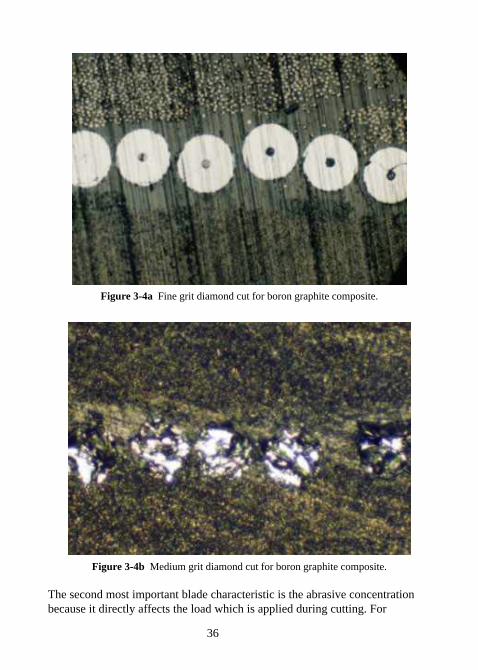
Perhaps the most important parameter for precision sectioning is the abrasivesize. Similar to grinding and polishing, finer abrasives produce less damage.For extremely brittle materials, finer abrasives are required to minimize andmanage the damage produced during sectioning. Sectioning with a fineabrasive wafering blade is often the only way that a specimen can be cut so thatthe final polished specimen represents the true microstructure. Examplesinclude: silicon computer chips, gallium arsenide, brittle glasses, ceramiccomposites, and boron-graphite composites. Figures 3-4a and 3-4b comparethe effects of cutting with a fine grit blade vs. a standard medium grit blade forsectioning a boron graphite golf shaft. As can be seen, the fine grit bladeproduces significantly less damage to boron fibers.
36
Figure 3-4a Fine grit diamond cut for boron graphite composite.
Figure 3-4b Medium grit diamond cut for boron graphite composite.
The second most important blade characteristic is the abrasive concentrationbecause it directly affects the load which is applied during cutting. For
37
example, brittle materials such as ceramics require higher effective loads toefficiently section; whereas, ductile materials such as metals require a higherabrasive concentration in order to have more cutting points. The result is thatlow concentration blades are recommended for sectioning hard brittle materialssuch as ceramics and high concentration blades are recommended for ductilematerials containing a large fraction of metal or plastic.
TIP: Minimizing the amount of damage created during sectioning cansignificantly reduce the amount of time required for grinding and polishing.
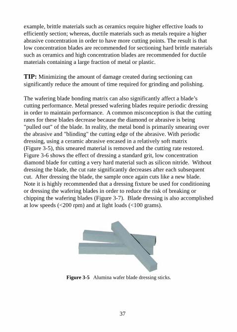
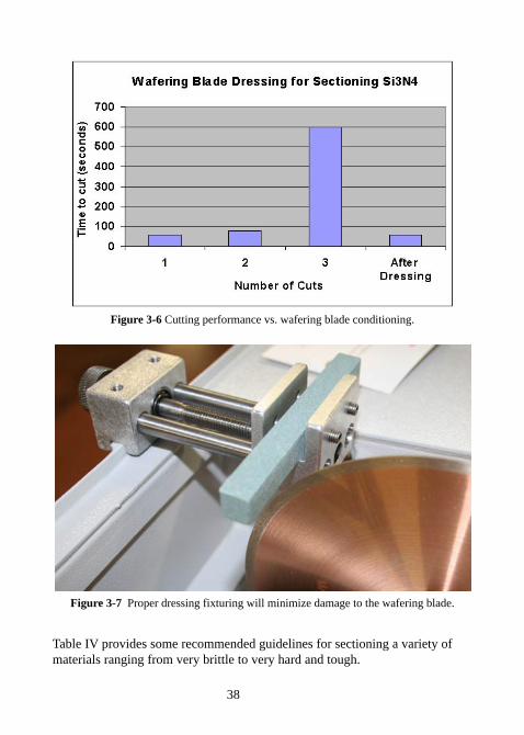
The wafering blade bonding matrix can also significantly affect a blade’scutting performance. Metal pressed wafering blades require periodic dressingin order to maintain performance. A common misconception is that the cuttingrates for these blades decrease because the diamond or abrasive is being"pulled out" of the blade. In reality, the metal bond is primarily smearing overthe abrasive and "blinding" the cutting edge of the abrasive. With periodicdressing, using a ceramic abrasive encased in a relatively soft matrix(Figure 3-5), this smeared material is removed and the cutting rate restored.Figure 3-6 shows the effect of dressing a standard grit, low concentrationdiamond blade for cutting a very hard material such as silicon nitride. Withoutdressing the blade, the cut rate significantly decreases after each subsequentcut. After dressing the blade, the sample once again cuts like a new blade.Note it is highly recommended that a dressing fixture be used for conditioningor dressing the wafering blades in order to reduce the risk of breaking orchipping the wafering blades (Figure 3-7). Blade dressing is also accomplishedat low speeds (<200 rpm) and at light loads (<100 grams).
Figure 3-5 Alumina wafer blade dressing sticks.
38
Figure 3-6 Cutting performance vs. wafering blade conditioning.
Figure 3-7 Proper dressing fixturing will minimize damage to the wafering blade.
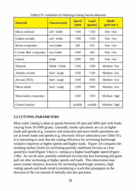
Table IV provides some recommended guidelines for sectioning a variety ofmaterials ranging from very brittle to very hard and tough.
39
TABLE IV. Guidelines for Wafering Cutting Various Materials
lairetaM citsiretcarahCdeepS)mpr(
daoL)smarg(
edalB).cnoc/tirg(
etartsbusnociliS elttirb/tfos 003< 001< wol/eniF
edinesramuillaG elttirb/tfos 002< 001< wol/eniF
setisopmocnoroB elttirbyrev 005 052 wol/eniF
setisopmocrebifcimareC elttirbyrev 0001 005 wol/eniF
sessalG elttirb 0001 005 wol/eniF
slareniM elttirb/elbairf 0051 005> wol/muideM
cimarecanimulA hguot/drah 0051 005> wol/muideM
)ZSP(ainocriZ hguot/drah 0051 008> wol/muideM
edirtinnociliS hguot/drah 0051 008> wol/muideM
setisopmocxirtamlateM 0051 005> hgih/muideM
esopruplareneG elbairav elbairav hgih/muideM
3.2 CUTTING PARAMETERS
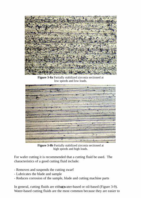
Most wafer cutting is done at speeds between 50 rpm and 5000 rpm with loadsvarying from 10-1000 grams. Generally, harder specimens are cut at higherloads and speeds (e.g. ceramics and minerals) and more brittle specimens arecut at lower loads and speeds (e.g. electronic silicon substrates) (see Table IV).It is interesting to note that the cutting efficiency for sectioning hard/toughceramics improves at higher speeds and higher loads. Figure 3.8 compares theresulting surface finish for sectioning partially stabilized zirconia at a lowspeed/low load (Figure 3-8a) vs. cutting at a higher load/higher speed (Figure3-8b). As can be seen, partially stabilized zirconia has less fracturing and grainpull out after sectioning at higher speeds and loads. This observation mayseem counter intuitive, however for sectioning hard/tough ceramics, highcutting speeds and loads result in producing a crack that propagates in thedirection of the cut instead of laterally into the specimen.
40
Figure 3-8a Partially stabilized zirconia sectioned atlow speeds and low loads.
Figure 3-8b Partially stabilized zirconia sectioned athigh speeds and high loads.
For wafer cutting it is recommended that a cutting fluid be used. Thecharacteristics of a good cutting fluid include:
- Removes and suspends the cutting swarf- Lubricates the blade and sample- Reduces corrosion of the sample, blade and cutting machine parts
In general, cutting fluids are either water-based or oil-based (Figure 3-9).Water-based cutting fluids are the most common because they are easier to
41
CHAPTER 4Specimen Mounting
4.0 SPECIMEN MOUNTING
The primary reasons for specimen mounting are to better hold the part to beground and polished, and to provide protection to the edges of the specimen.Secondarily, mounted specimens are easier to fixture into automated machinesor to hold manually. The orientation of the specimen can also be more easilycontrolled by fixturing it and then setting it in place via mounting.Metallographic mounting is accomplished by casting the specimen into acastable plastic material or by compression mounting the plastic under pressureand temperature.
4.1 CASTABLE MOUNTING
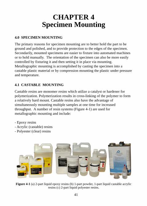
Castable resins are monomer resins which utilize a catalyst or hardener forpolymerization. Polymerization results in cross-linking of the polymer to forma relatively hard mount. Castable resins also have the advantage ofsimultaneously mounting multiple samples at one time for increasedthroughput. A number of resin systems (Figure 4-1) are used formetallographic mounting and include:
- Epoxy resins- Acrylic (castable) resins- Polyester (clear) resins
Figure 4-1 (a) 2-part liquid epoxy resins (b) 1-part powder, 1-part liquid castable acrylicresins (c) 2-part liquid polyester resins.
42
Table VI lists the common properties of epoxy, acrylic and polyester resins.
TABLE VI. Castable Mounting Properties
YTREPORP YXOPE CILYRCA NISERRETSEYLOP
kaePerutarepmeT
F°573-001 F°051 F°001
DerohSssendraH
28 08 67
emiTeruCotsetunim03
sruoh8setunim8-5 sruoh8-6
stnemmoC,ssendrahetaredoM
,egaknirhswoltnerapsnart
,eructsafyreV,tneculsnart
egaknirhsemosraelcretaw,tnerapsnarT
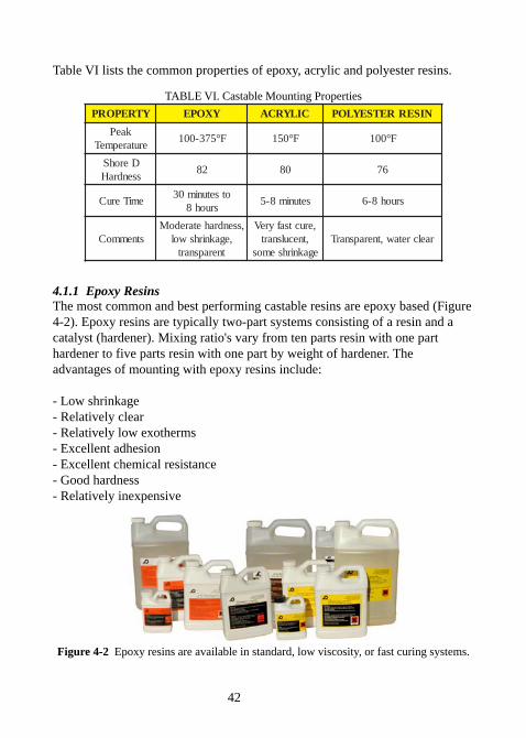
4.1.1 Epoxy ResinsThe most common and best performing castable resins are epoxy based (Figure4-2). Epoxy resins are typically two-part systems consisting of a resin and acatalyst (hardener). Mixing ratio's vary from ten parts resin with one parthardener to five parts resin with one part by weight of hardener. Theadvantages of mounting with epoxy resins include:
- Low shrinkage- Relatively clear- Relatively low exotherms- Excellent adhesion- Excellent chemical resistance- Good hardness- Relatively inexpensive
Figure 4-2 Epoxy resins are available in standard, low viscosity, or fast curing systems.
43
Epoxy curing times are dependent upon a number of variables including:- Volume of mounting resin (larger mounts cure faster).- Thermal mass of specimen (larger specimens absorb heat and therefore require longer curing time).- Specimen material properties.- Initial resin temperature (higher temperatures cure faster).- Ambient temperature (higher temperatures cure faster).- Relative humidity and shelf life (absorption of water degrades resin and shortens shelf life).- Mounting mold (plastic, phenolic rings, rubber absorb heat differently).
As a general rule, curing times can vary from 30-45 minutes for fast curingepoxies up to 24 hours for slower curing epoxies. For metallographic epoxiesto grind properly, the hardness needs to be at least a Shore D80. Note thatepoxy resins typically will continue to harden over a longer period of time(maximum hardness, Shore D90).
In some cases, the curing time and temperature may need to be controlled tocompensate for the above variables. For example, an 8-hour resin system canbe cured in 30-45 minutes by preheating the resin to approximately 120°F(50°C) prior to mixing and then curing at room temperature. This procedureinitiates the catalytic reaction sooner; however, this may also increase themaximum exotherm temperature.
TIP: Preheat the specimen to initiate the epoxy resin at the surface of themount and thus have the epoxy shrink towards the sample for better edgeretention.
Conversely, the resin curing cycle can be slowed or reduced by decreasing thecuring temperature by forcing air over the curing mounts (fume hood or fan),placing the mounts into a water bath, or curing in a refrigerator. In these cases,care must be taken to not stop the reaction; however if this does occur or theresin is too soft after curing, heating it to 100-120°F for several hours shouldpush the reaction to completion and the mount should be hard after cooling toroom temperature.
Table VII lists the relative properties for several metallographic epoxy resinsystems.
44
TABLE VII. Castable Epoxy Mounting Properties
YXOPEdradnatS
yxopEgnitnuoMkciuQ
yxopEytisocsiVwoL
yxopE
scitsiretcarahC tsocrewoL eructsaF
,ytisocsivrewoLrewol,reraelc
l,mrehtoxeegaknirhswo
emiTeruC sruoh5-1 setunim03 sruoh2
oitargnixiM)thgiew(
)renedrah:niser(1:5 1:01 1:01
mrehtoxEkaePsmarg02smarg03
F°003F°003
F°053F°573
F°021F°051
roloCthgilsotraelC
tnitwolleytnitwolleythgilS raelC
ytisocsiV muideM muideM woL
egaknirhS etaredoM hgiH woL
4.1.2 Acrylic Castable Resins
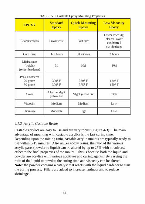
Castable acrylics are easy to use and are very robust (Figure 4-3). The mainadvantage of mounting with castable acrylics is the fast curing time.Depending upon the mixing ratio, castable acrylic mounts are typically ready touse within 8-15 minutes. Also unlike epoxy resins, the ratio of the variousacrylic parts (powder to liquid) can be altered by up to 25% with no adverseeffect to the final properties of the mount. This is because both the liquid andpowder are acrylics with various additives and curing agents. By varying theratio of the liquid to powder, the curing time and viscosity can be altered.Note: the powder contains a catalyst that reacts with the liquid hardener to startthe curing process. Fillers are added to increase hardness and to reduceshrinkage.
45
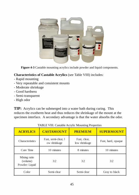
Figure 4-3 Castable mounting acrylics include powder and liquid components.
Characteristics of Castable Acrylics (see Table VIII) includes:- Rapid mounting- Very repeatable and consistent mounts- Moderate shrinkage- Good hardness- Semi-transparent- High odor
TIP: Acrylics can be submerged into a water bath during curing. Thisreduces the exotherm heat and thus reduces the shrinkage of the mount at thespecimen interface. A secondary advantage is that the water absorbs the odor.
TABLE VIII. Castable Acrylic Mounting Properties
SCILYRCA TNUOMATSAC MUIMERP TNUOMREPUS
scitsiretcarahCl,raelc-imes,tsaF
egaknirhswo,raelc,tsaFegaknirhswol
euqapo,drah,tsaF
emiTeruC setunim01 setunim8 setunim01
oitargnixiM)emulov(
diuqiL:redwoP2:3 2:3 2:3
roloC raelc-imeS raelc-imeS kcalbotyarG
46
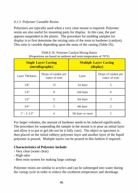
4.1.3 Polyester Castable Resins
Polyesters are typically used when a very clear mount is required. Polyesterresins are also useful for mounting parts for display. In this case, the partappears suspended in the plastic. The procedure for molding samples fordisplay is to first determine the mixing ratio of the resin to hardener (catalyst).This ratio is variable depending upon the mass of the casting (Table IX).
TABLE IX. Polyester Catalyst Mixing Ratios(Proportions are based on ambient and resin temperature of 70°F)
gnitsaCreyaLelgniS)cihpargollatem(
gnitsaCreyaLelpitluM)yalpsid(
ssenkcihTreyaLreptsylatacfosporD
niserfoecnuoreyaL
reptsylatacfosporDniserfoecnuo
"8/1 51 reyalts1 5
"4/1 8 reyaldn2 4
"2/1 6 reyaldr3 3
"4/3 5 reyalht4 2
"2/1-1-"1 4 eromroreyalht5 2
For larger volumes, the amount of hardener needs to be reduced significantly.The procedure for suspending the sample in the mount is to pour an initial layerand allow it to pot or gel (do not let it fully cure). The object or specimen isthen placed on the initial rubbery polyester layer and another layer of the liquidpolyester is poured. Multiple layers can be poured in this fashion if required.
Characteristics of Polyester include:- Very clear (water clear)- High odor- Best resin system for making large castings
Polyester resins are similar to acrylics and can be submerged into water duringthe curing cycle in order to reduce the exotherm temperature and shrinkage.
47
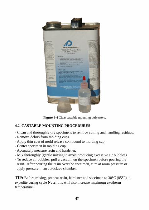
Figure 4-4 Clear castable mounting polyesters.
4.2 CASTABLE MOUNTING PROCEDURES
- Clean and thoroughly dry specimens to remove cutting and handling residues.- Remove debris from molding cups.- Apply thin coat of mold release compound to molding cup.- Center specimen in molding cup.- Accurately measure resin and hardener.- Mix thoroughly (gentle mixing to avoid producing excessive air bubbles).- To reduce air bubbles, pull a vacuum on the specimen before pouring the resin. After pouring the resin over the specimen, cure at room pressure or apply pressure in an autoclave chamber.
TIP: Before mixing, preheat resin, hardener and specimen to 30°C (85°F) toexpedite curing cycle Note: this will also increase maximum exothermtemperature.
48
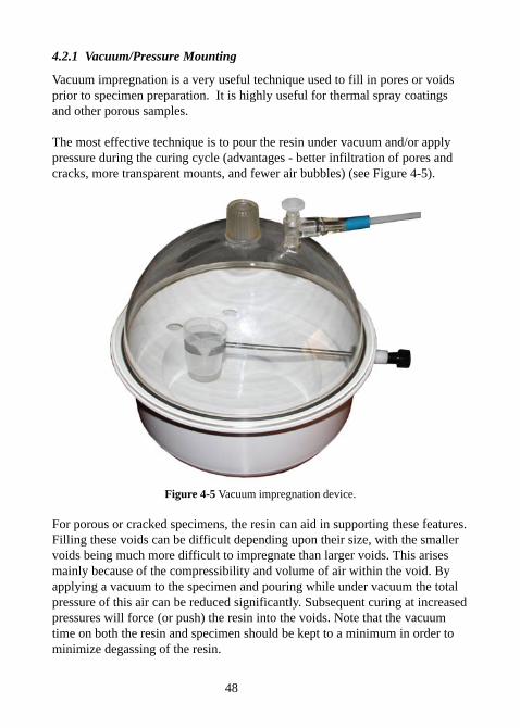
4.2.1 Vacuum/Pressure Mounting
Vacuum impregnation is a very useful technique used to fill in pores or voidsprior to specimen preparation. It is highly useful for thermal spray coatingsand other porous samples.
The most effective technique is to pour the resin under vacuum and/or applypressure during the curing cycle (advantages - better infiltration of pores andcracks, more transparent mounts, and fewer air bubbles) (see Figure 4-5).
Figure 4-5 Vacuum impregnation device.
For porous or cracked specimens, the resin can aid in supporting these features.Filling these voids can be difficult depending upon their size, with the smallervoids being much more difficult to impregnate than larger voids. This arisesmainly because of the compressibility and volume of air within the void. Byapplying a vacuum to the specimen and pouring while under vacuum the totalpressure of this air can be reduced significantly. Subsequent curing at increasedpressures will force (or push) the resin into the voids. Note that the vacuumtime on both the resin and specimen should be kept to a minimum in order tominimize degassing of the resin.
49
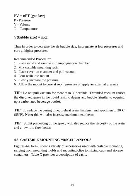
PV = nRT (gas law)P - PressureV - VolumeT - Temperature
V(bubble size) = nRT PThus in order to decrease the air bubble size, impregnate at low pressures andcure at higher pressures.
Recommended Procedure:1. Place mold and sample into impregnation chamber2. Mix castable mounting resin3. Place cover on chamber and pull vacuum4. Pour resin into mount5. Slowly increase the pressure6. Allow the mount to cure at room pressure or apply an external pressure.
TIP: Do not pull vacuum for more than 60 seconds. Extended vacuum causesthe dissolved gases in the liquid resin to degass and bubble (similar to openingup a carbonated beverage bottle).
TIP: To reduce the curing time, preheat resin, hardener and specimen to 30°C(85°F). Note: this will also increase maximum exotherm.
TIP: Slight preheating of the epoxy will also reduce the viscosity of the resinand allow it to flow better.
4.3 CASTABLE MOUNTING MISCELLANEOUS
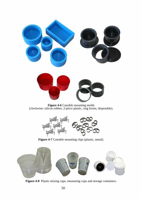
Figures 4-6 to 4-8 show a variety of accessories used with castable mounting,ranging from mounting molds and mounting clips to mixing cups and storagecontainers. Table X provides a description of each..
50
Figure 4-6 Castable mounting molds(clockwise: silicon rubber, 2-piece plastic, ring forms, disposable).
Figure 4-7 Castable mounting clips (plastic, metal).
Figure 4-8 Plastic mixing cups, measuring cups and storage containers.
51
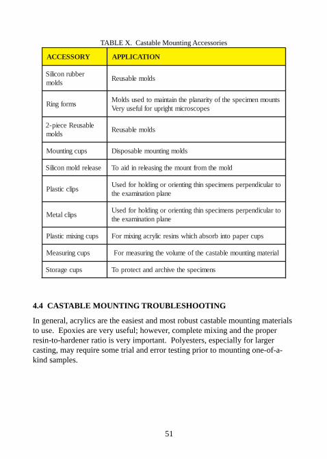
TABLE X. Castable Mounting Accessories
YROSSECCA NOITACILPPA
rebburnociliSsdlom
sdlomelbasueR
smrofgniRstnuomnemicepsehtfoytiranalpehtniatniamotdesusdloM
sepocsorcimthgirpuroflufesuyreV
elbasueReceip-2sdlom
sdlomelbasueR
spucgnitnuoM sdlomgnitnuomelbasopsiD
esaelerdlomnociliS dlomehtmorftnuomehtgnisaelernidiaoT
spilccitsalPotralucidneprepsnemicepsnihtgnitneirorognidlohrofdesU
enalpnoitanimaxeeht
spilclateMotralucidneprepsnemicepsnihtgnitneirorognidlohrofdesU
enalpnoitanimaxeeht
spucgniximcitsalP spucrepapotnibrosbahcihwsnisercilyrcagniximroF
spucgnirusaeM lairetamgnitnuomelbatsacehtfoemulovehtgnirusaemroF
spucegarotS snemicepsehtevihcradnatcetorpoT
4.4 CASTABLE MOUNTING TROUBLESHOOTING
In general, acrylics are the easiest and most robust castable mounting materialsto use. Epoxies are very useful; however, complete mixing and the properresin-to-hardener ratio is very important. Polyesters, especially for largercasting, may require some trial and error testing prior to mounting one-of-a-kind samples.
52
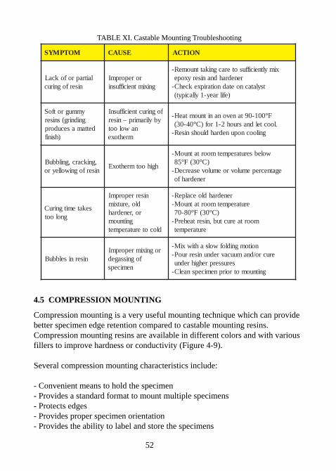
TABLE XI. Castable Mounting Troubleshooting
MOTPMYS ESUAC NOITCA
laitraprofokcaLniserfogniruc
roreporpmIgniximtneiciffusni
ximyltneiciffusoteracgnikattnuomeR-renedrahdnaniseryxope
tsylatacnoetadnoitaripxekcehC-)efilraey-1yllacipyt(
ymmugrotfoSgnidnirg(sniser
dettamasecudorp)hsinif
fogniructneiciffusnIybyliramirp–niser
nawolootmrehtoxe
01-09tanevonanitnuomtaeH- 0 F°4-03( 0 .loocteldnasruoh2-1rof)C°
gniloocnopunedrahdluohsniseR-
,gnikcarc,gnilbbuBniserfogniwolleyro
hgihootmrehtoxE
wolebserutarepmetmoortatnuoM-58 ° 3(F 0 )C°
egatnecrepemulovroemulovesaerceD-renedrahfo
sekatemitgniruCgnoloot
niserreporpmIdlo,erutximro,renedrah
gnitnuomdlocoterutarepmet
renedrahdloecalpeR-erutarepmetmoortatnuoM-
8-07 0 03(F° ° )Cmoortaeructub,nisertaeherP-
erutarepmet
niserniselbbuBrogniximreporpmI
fognissagednemiceps
noitomgnidlofwolsahtiwxiM-erucro/dnamuucavrednuniserruoP-
serusserprehgihrednugnitnuomotroirpnemicepsnaelC-
4.5 COMPRESSION MOUNTING
Compression mounting is a very useful mounting technique which can providebetter specimen edge retention compared to castable mounting resins.Compression mounting resins are available in different colors and with variousfillers to improve hardness or conductivity (Figure 4-9).
Several compression mounting characteristics include:
- Convenient means to hold the specimen- Provides a standard format to mount multiple specimens- Protects edges- Provides proper specimen orientation- Provides the ability to label and store the specimens
53
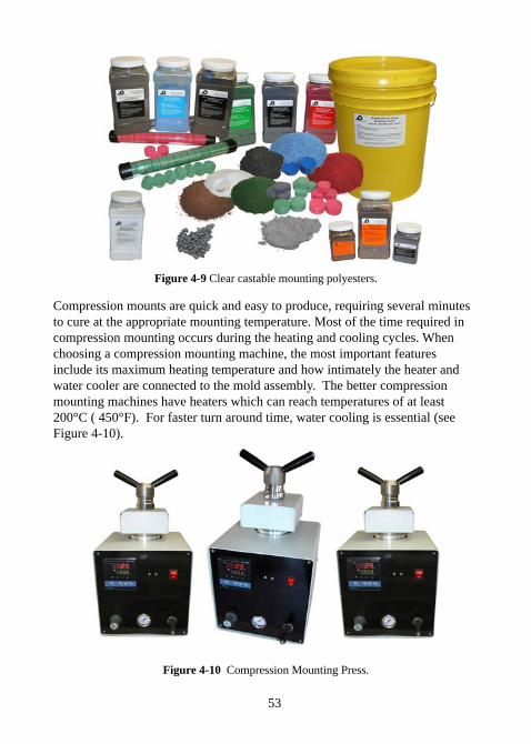
Figure 4-9 Clear castable mounting polyesters.
Compression mounts are quick and easy to produce, requiring several minutesto cure at the appropriate mounting temperature. Most of the time required incompression mounting occurs during the heating and cooling cycles. Whenchoosing a compression mounting machine, the most important featuresinclude its maximum heating temperature and how intimately the heater andwater cooler are connected to the mold assembly. The better compressionmounting machines have heaters which can reach temperatures of at least200°C ( 450°F). For faster turn around time, water cooling is essential (seeFigure 4-10).
Figure 4-10 Compression Mounting Press.
54
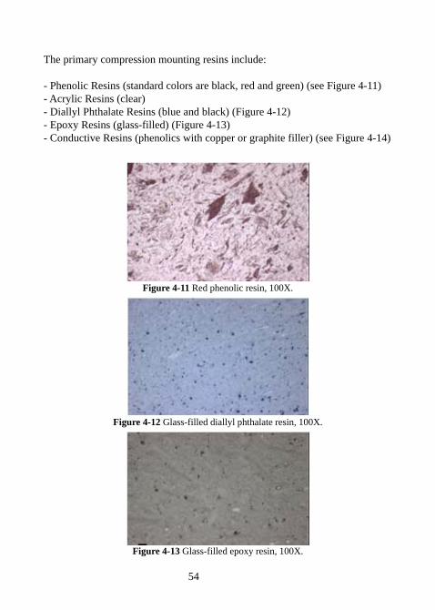
The primary compression mounting resins include:
- Phenolic Resins (standard colors are black, red and green) (see Figure 4-11)- Acrylic Resins (clear)- Diallyl Phthalate Resins (blue and black) (Figure 4-12)- Epoxy Resins (glass-filled) (Figure 4-13)- Conductive Resins (phenolics with copper or graphite filler) (see Figure 4-14)
Figure 4-11 Red phenolic resin, 100X.
Figure 4-12 Glass-filled diallyl phthalate resin, 100X.
Figure 4-13 Glass-filled epoxy resin, 100X.
55
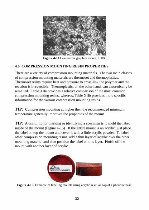
Figure 4-14 Conductive graphite mount, 100X.
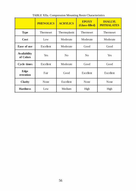
4.6 COMPRESSION MOUNTING RESIN PROPERTIES
There are a variety of compression mounting materials. The two main classesof compression mounting materials are thermoset and thermoplastics.Thermoset resins require heat and pressure to cross-link the polymer and thereaction is irreversible. Thermoplastic, on the other hand, can theoretically beremelted. Table XIIa provides a relative comparison of the most commoncompression mounting resins, whereas, Table XIIb provides more specificinformation for the various compression mounting resins.
TIP: Compression mounting at higher then the recommended minimumtemperature generally improves the properties of the mount.
TIP: A useful tip for marking or identifying a specimen is to mold the labelinside of the mount (Figure 4-15). If the entire mount is an acrylic, just placethe label on top the mount and cover it with a little acrylic powder. To labelother compression mounting resins, add a thin layer of acrylic over the othermounting material and then position the label on this layer. Finish off themount with another layer of acrylic.
Figure 4-15. Example of labeling mounts using acrylic resin on top of a phenolic base.
56
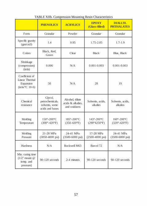
TABLE XIIa. Compression Mounting Resin Characteristics
SCILONEHP SCILYRCAYXOPE
)dellif-ssalG(LYLLAID
SETALAHTHP
epyT tesomrehT citsalpomrehT tesomrehT tesomrehT
tsoC woL etaredoM etaredoM etaredoM
esufoesaE tnellecxE etaredoM dooG dooG
ytilibaliavAsroloCfo
seY oN oN seY
semitelcyC tnellecxE etaredoM dooG dooG
egdEnoitneter
riaF dooG tnellecxE tnellecxE
ytiralC enoN tnellecxE enoN enoN
ssendraH woL muideM hgiH hgiH
57
TABLE XIIb. Compression Mounting Resin Characteristics
SCILONEHP SCILYRCAYXOPE
)dellif-ssalG(LYLLAID
SETALAHTHP
mroF ralunarG redwoP ralunarG ralunarG
ytivargcificepS)3mc/mg(
4.1 59.0 50.2-57.1 9.1-7.1
sroloC,deR,kcalB
neerGraelC kcalB kcalB,eulB
egaknirhS)noisserpmoc(
)ni/ni(600.0 A/N 300.0-100.0 300.0-100.0
fotneiciffeoClamrehTraeniL
noisnapxE)6-01C°/ni/ni(
05 A/N 82 91
lacimehCecnatsiser
,locylG,slacimehcortep
emos,stnevlossesabdnasdica
etulid,lohoclA,seilakla&sdica
srezidixodna
,sdica,stnevloSseilakla
,sdica,stnevloSseilakla
gnidloMerutarepmeT
C°002-°051)F°024-°003(
C°002-°581)F°024-053(
C°002-°341)F°0524°092(
C°002-°061)F°024-°023(
gnidloMerusserP
aPM82-12)isp0004-0503(
aPM14-42)isp0006-0053(
aPM82-71)isp0004-0052(
aPM14-42)isp0006-0053(
ssendraH A/N 36MllewkcoR 27locraB A/N
emitgniruc.niM@tnuom"2/1(
dna.pmet)erusserp
sdnoces021-09 setunim4-2 sdnoces021-09 sdnoces021-09
58
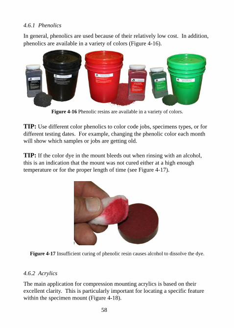
4.6.1 Phenolics
In general, phenolics are used because of their relatively low cost. In addition,phenolics are available in a variety of colors (Figure 4-16).
Figure 4-16 Phenolic resins are available in a variety of colors.
TIP: Use different color phenolics to color code jobs, specimens types, or fordifferent testing dates. For example, changing the phenolic color each monthwill show which samples or jobs are getting old.
TIP: If the color dye in the mount bleeds out when rinsing with an alcohol,this is an indication that the mount was not cured either at a high enoughtemperature or for the proper length of time (see Figure 4-17).
Figure 4-17 Insufficient curing of phenolic resin causes alcohol to dissolve the dye.
4.6.2 Acrylics
The main application for compression mounting acrylics is based on theirexcellent clarity. This is particularly important for locating a specific featurewithin the specimen mount (Figure 4-18).
59
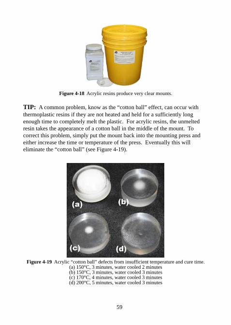
Figure 4-18 Acrylic resins produce very clear mounts.
TIP: A common problem, know as the “cotton ball” effect, can occur withthermoplastic resins if they are not heated and held for a sufficiently longenough time to completely melt the plastic. For acrylic resins, the unmeltedresin takes the appearance of a cotton ball in the middle of the mount. Tocorrect this problem, simply put the mount back into the mounting press andeither increase the time or temperature of the press. Eventually this willeliminate the “cotton ball” (see Figure 4-19).
Figure 4-19 Acrylic “cotton ball” defects from insufficient temperature and cure time.(a) 150°C, 3 minutes, water cooled 2 minutes(b) 150°C, 3 minutes, water cooled 3 minutes(c) 170°C, 4 minutes, water cooled 3 minutes(d) 200°C, 5 minutes, water cooled 3 minutes
60
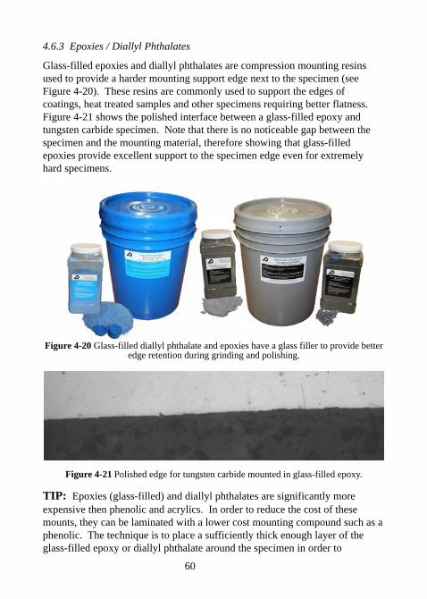
4.6.3 Epoxies / Diallyl Phthalates
Glass-filled epoxies and diallyl phthalates are compression mounting resinsused to provide a harder mounting support edge next to the specimen (seeFigure 4-20). These resins are commonly used to support the edges ofcoatings, heat treated samples and other specimens requiring better flatness.Figure 4-21 shows the polished interface between a glass-filled epoxy andtungsten carbide specimen. Note that there is no noticeable gap between thespecimen and the mounting material, therefore showing that glass-filledepoxies provide excellent support to the specimen edge even for extremelyhard specimens.
Figure 4-20 Glass-filled diallyl phthalate and epoxies have a glass filler to provide betteredge retention during grinding and polishing.
Figure 4-21 Polished edge for tungsten carbide mounted in glass-filled epoxy.
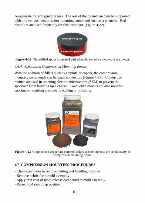
TIP: Epoxies (glass-filled) and diallyl phthalates are significantly moreexpensive then phenolic and acrylics. In order to reduce the cost of thesemounts, they can be laminated with a lower cost mounting compound such as aphenolic. The technique is to place a sufficiently thick enough layer of theglass-filled epoxy or diallyl phthalate around the specimen in order to
61
compensate for any grinding loss. The rest of the mount can then be supportedwith a lower cost compression mounting compound such as a phenolic. Redphenolics are used frequently for this technique (Figure 4-22).
Figure 4-22 Glass-filled epoxy laminated with phenolic to reduce the cost of the mount.
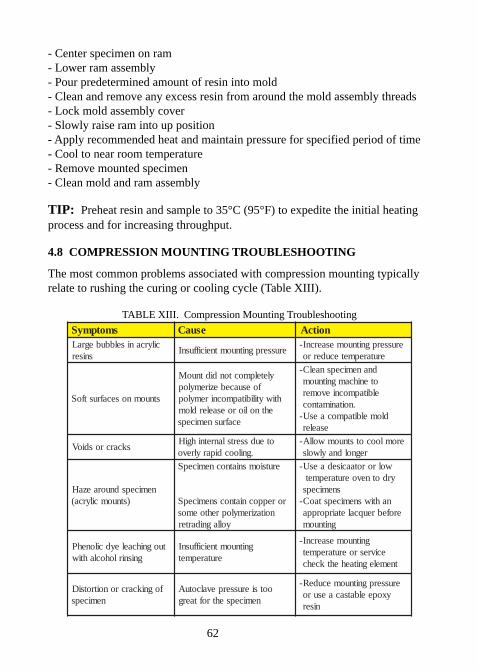
4.6.4 Specialized Compression Mounting Resins
With the addition of fillers such as graphite or copper, the compressionmounting compounds can be made conductive (Figure 4-23). Conductivemounts are used in scanning electron microscopes (SEM) to prevent thespecimen from building up a charge. Conductive mounts are also used forspecimens requiring electrolytic etching or polishing.
Figure 4-23 Graphite and copper are common fillers used to increase the conductivity ofcompression mounting resins.
4.7 COMPRESSION MOUNTING PROCEDURES
- Clean specimens to remove cutting and handling residues- Remove debris from mold assembly- Apply thin coat of mold release compound to mold assembly- Raise mold ram to up position
62
- Center specimen on ram- Lower ram assembly- Pour predetermined amount of resin into mold- Clean and remove any excess resin from around the mold assembly threads- Lock mold assembly cover- Slowly raise ram into up position- Apply recommended heat and maintain pressure for specified period of time- Cool to near room temperature- Remove mounted specimen- Clean mold and ram assembly
TIP: Preheat resin and sample to 35°C (95°F) to expedite the initial heatingprocess and for increasing throughput.
4.8 COMPRESSION MOUNTING TROUBLESHOOTING
The most common problems associated with compression mounting typicallyrelate to rushing the curing or cooling cycle (Table XIII).
TABLE XIII. Compression Mounting Troubleshooting
smotpmyS esuaC noitcAcilyrcaniselbbubegraL
snisererusserpgnitnuomtneiciffusnI
erusserpgnitnuomesaercnI-erutarepmetecuderro
stnuomnosecafrustfoS
yletelpmoctondidtnuoMfoesuacebeziremylop
htiwytilibitapmocniremylopehtnolioroesaelerdlom
ecafrusnemiceps
dnanemicepsnaelC-otenihcamgnitnuomelbitapmocnievomer
.noitanimatnocdlomelbitapmocaesU-
esaeler
skcarcrosdioVoteudssertslanretnihgiH
.gniloocdiparylrevoeromloocotstnuomwollA-
regnoldnaylwols
nemicepsdnuoraezaH)stnuomcilyrca(
erutsiomsniatnocnemicepS
roreppocniatnocsnemicepSnoitaziremyloprehtoemos
yollagnidarter
wolrorotaacisedaesU-yrdotnevoerutarepmet
snemicepsnahtiwsnemicepstaoC-
erofebreuqcaletairporppagnitnuom
tuognihcaeleydcilonehPgnisnirlohoclahtiw
gnitnuomtneiciffusnIerutarepmet
gnitnuomesaercnI-ecivresroerutarepmet
tnemelegnitaehehtkcehc
fognikcarcronoitrotsiDnemiceps
ootsierusserpevalcotuAnemicepsehtroftaerg
erusserpgnitnuomecudeR-yxopeelbatsacaesuro
niser
63
CHAPTER 5Abrasive Grinding
5.0 ABRASIVE GRINDING
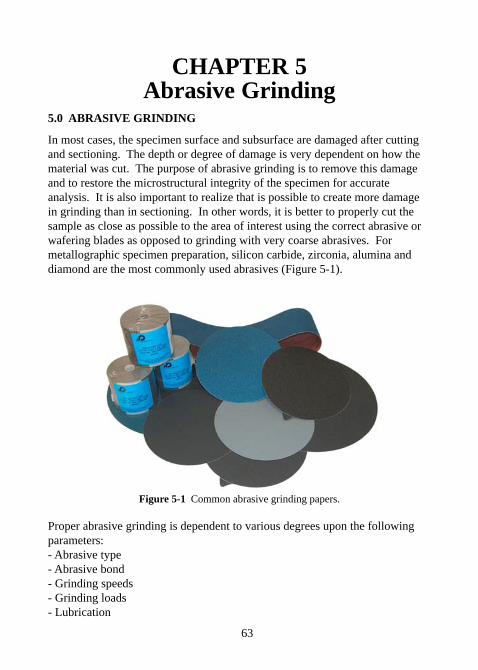
In most cases, the specimen surface and subsurface are damaged after cuttingand sectioning. The depth or degree of damage is very dependent on how thematerial was cut. The purpose of abrasive grinding is to remove this damageand to restore the microstructural integrity of the specimen for accurateanalysis. It is also important to realize that is possible to create more damagein grinding than in sectioning. In other words, it is better to properly cut thesample as close as possible to the area of interest using the correct abrasive orwafering blades as opposed to grinding with very coarse abrasives. Formetallographic specimen preparation, silicon carbide, zirconia, alumina anddiamond are the most commonly used abrasives (Figure 5-1).
Figure 5-1 Common abrasive grinding papers.
Proper abrasive grinding is dependent to various degrees upon the followingparameters:- Abrasive type- Abrasive bond- Grinding speeds- Grinding loads- Lubrication
64
5.1 ABRASIVES USED FOR GRINDINGThe following description offers a more detailed explanation of these abrasivegrinding variables. Perhaps the most significant variable is the abrasive andhow it interacts with the specimen. The properties of the more commonly usedabrasives for metallographic cutting, grinding and polishing are shown in TableXIV.
TABLE XIV. Common Metallographic Abrasives
evisarbA ssendraH)KH-poonK(
ssendraH)shoM(
erutcurtSlatsyrC
aciliS 028 7-6 lanogairt-lanogaxeH
animulA 0512 9-8 lardehobmohr-lanogaxeH)sesahpammagroahpla(
edibraCnociliS 0842 5.9-1.9 lardehobmohr-lanogaxeH
edibraCnoroB 0572 01-9 lardehobmohR
nocriZ 0051 8-5.7 lanogarteT
dnomaiD 0008 01 lanogaxeh-cibuC
5.1.1 Silicon Carbide
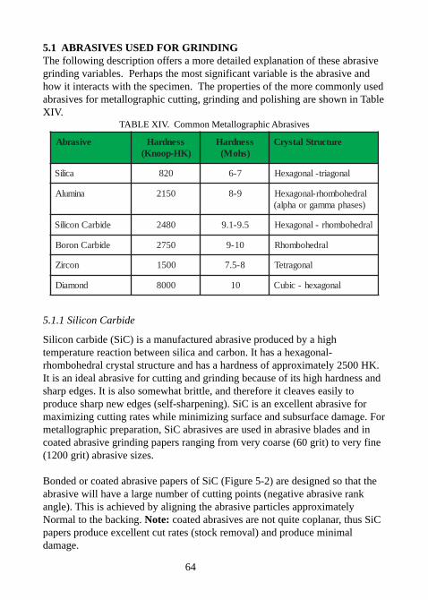
Silicon carbide (SiC) is a manufactured abrasive produced by a hightemperature reaction between silica and carbon. It has a hexagonal-rhombohedral crystal structure and has a hardness of approximately 2500 HK.It is an ideal abrasive for cutting and grinding because of its high hardness andsharp edges. It is also somewhat brittle, and therefore it cleaves easily toproduce sharp new edges (self-sharpening). SiC is an excellent abrasive formaximizing cutting rates while minimizing surface and subsurface damage. Formetallographic preparation, SiC abrasives are used in abrasive blades and incoated abrasive grinding papers ranging from very coarse (60 grit) to very fine(1200 grit) abrasive sizes.
Bonded or coated abrasive papers of SiC (Figure 5-2) are designed so that theabrasive will have a large number of cutting points (negative abrasive rankangle). This is achieved by aligning the abrasive particles approximatelyNormal to the backing. Note: coated abrasives are not quite coplanar, thus SiCpapers produce excellent cut rates (stock removal) and produce minimaldamage.
65
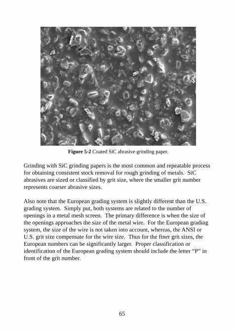
Figure 5-2 Coated SiC abrasive grinding paper.
Grinding with SiC grinding papers is the most common and repeatable processfor obtaining consistent stock removal for rough grinding of metals. SiCabrasives are sized or classified by grit size, where the smaller grit numberrepresents coarser abrasive sizes.
Also note that the European grading system is slightly different than the U.S.grading system. Simply put, both systems are related to the number ofopenings in a metal mesh screen. The primary difference is when the size ofthe openings approaches the size of the metal wire. For the European gradingsystem, the size of the wire is not taken into account, whereas, the ANSI orU.S. grit size compensate for the wire size. Thus for the finer grit sizes, theEuropean numbers can be significantly larger. Proper classification oridentification of the European grading system should include the letter “P” infront of the grit number.
66
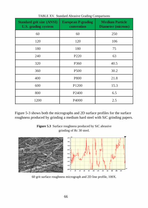
TABLE XV. Standard Abrasive Grading Comparisons
)ISNA(ezistirgdradnatSmetsysgnidarg.S.U
gnidarg-PnaeporuEnoitnevnoc
elcitraPmuideM)snorcim(retemaiD
06 06 052
021 021 601
081 081 57
042 022P 36
023 063P 5.04
063 005P 2.03
004 008P 8.12
006 0021P 3.51
008 0042P 5.6
0021 0004P 5.2
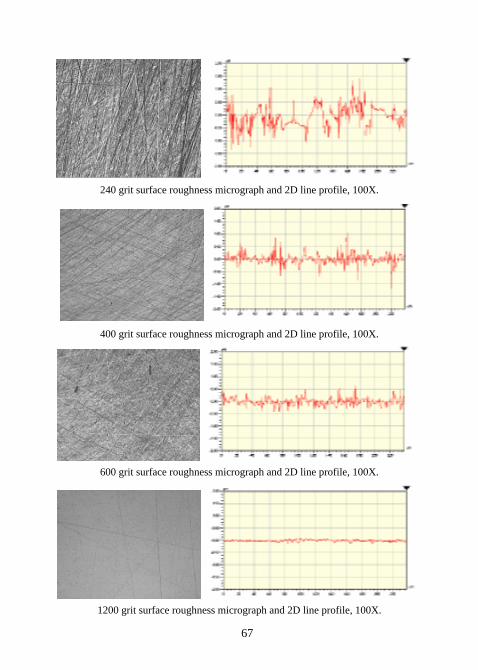
Figure 5-3 shows both the micrographs and 2D surface profiles for the surfaceroughness produced by grinding a medium hard steel with SiC grinding papers.
Figure 5.3 Surface roughness produced by SiC abrasivegrinding of Rc 30 steel.
60 grit surface roughness micrograph and 2D line profile, 100X.
67
240 grit surface roughness micrograph and 2D line profile, 100X.
400 grit surface roughness micrograph and 2D line profile, 100X.
600 grit surface roughness micrograph and 2D line profile, 100X.
1200 grit surface roughness micrograph and 2D line profile, 100X.
68
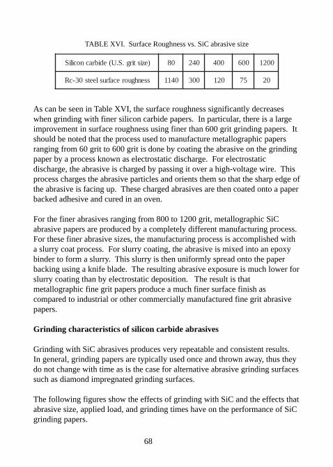
TABLE XVI. Surface Roughness vs. SiC abrasive size
)ezistirg.S.U(edibracnociliS 08 042 004 006 0021
ssenhguorecafrusleets03-cR 0411 003 021 57 02
As can be seen in Table XVI, the surface roughness significantly decreaseswhen grinding with finer silicon carbide papers. In particular, there is a largeimprovement in surface roughness using finer than 600 grit grinding papers. Itshould be noted that the process used to manufacture metallographic papersranging from 60 grit to 600 grit is done by coating the abrasive on the grindingpaper by a process known as electrostatic discharge. For electrostaticdischarge, the abrasive is charged by passing it over a high-voltage wire. Thisprocess charges the abrasive particles and orients them so that the sharp edge ofthe abrasive is facing up. These charged abrasives are then coated onto a paperbacked adhesive and cured in an oven.
For the finer abrasives ranging from 800 to 1200 grit, metallographic SiCabrasive papers are produced by a completely different manufacturing process.For these finer abrasive sizes, the manufacturing process is accomplished witha slurry coat process. For slurry coating, the abrasive is mixed into an epoxybinder to form a slurry. This slurry is then uniformly spread onto the paperbacking using a knife blade. The resulting abrasive exposure is much lower forslurry coating than by electrostatic deposition. The result is thatmetallographic fine grit papers produce a much finer surface finish ascompared to industrial or other commercially manufactured fine grit abrasivepapers.
Grinding characteristics of silicon carbide abrasives
Grinding with SiC abrasives produces very repeatable and consistent results.In general, grinding papers are typically used once and thrown away, thus theydo not change with time as is the case for alternative abrasive grinding surfacessuch as diamond impregnated grinding surfaces.
The following figures show the effects of grinding with SiC and the effects thatabrasive size, applied load, and grinding times have on the performance of SiCgrinding papers.
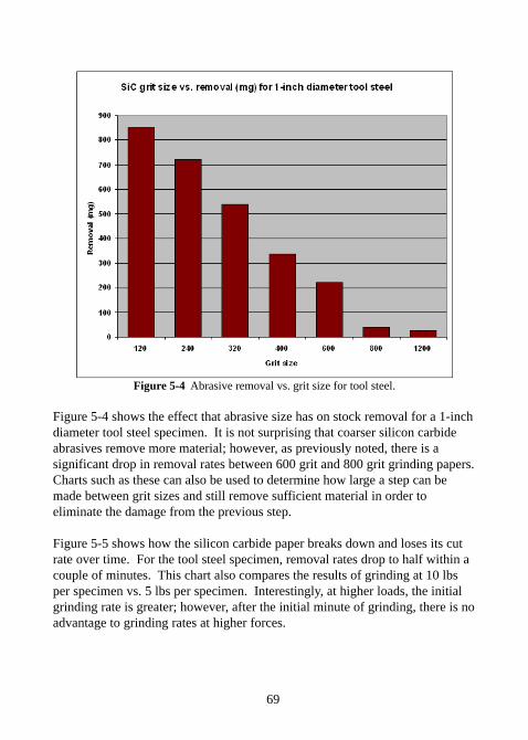
69
Figure 5-4 Abrasive removal vs. grit size for tool steel.
Figure 5-4 shows the effect that abrasive size has on stock removal for a 1-inchdiameter tool steel specimen. It is not surprising that coarser silicon carbideabrasives remove more material; however, as previously noted, there is asignificant drop in removal rates between 600 grit and 800 grit grinding papers.Charts such as these can also be used to determine how large a step can bemade between grit sizes and still remove sufficient material in order toeliminate the damage from the previous step.
Figure 5-5 shows how the silicon carbide paper breaks down and loses its cutrate over time. For the tool steel specimen, removal rates drop to half within acouple of minutes. This chart also compares the results of grinding at 10 lbsper specimen vs. 5 lbs per specimen. Interestingly, at higher loads, the initialgrinding rate is greater; however, after the initial minute of grinding, there is noadvantage to grinding rates at higher forces.
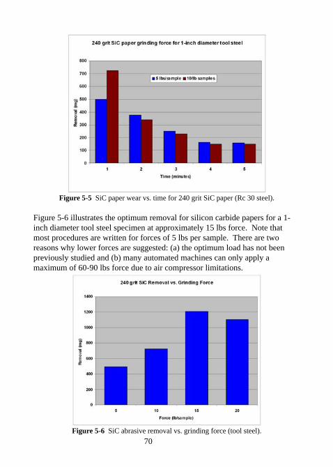
70
Figure 5-5 SiC paper wear vs. time for 240 grit SiC paper (Rc 30 steel).
Figure 5-6 illustrates the optimum removal for silicon carbide papers for a 1-inch diameter tool steel specimen at approximately 15 lbs force. Note thatmost procedures are written for forces of 5 lbs per sample. There are tworeasons why lower forces are suggested: (a) the optimum load has not beenpreviously studied and (b) many automated machines can only apply amaximum of 60-90 lbs force due to air compressor limitations.
Figure 5-6 SiC abrasive removal vs. grinding force (tool steel).
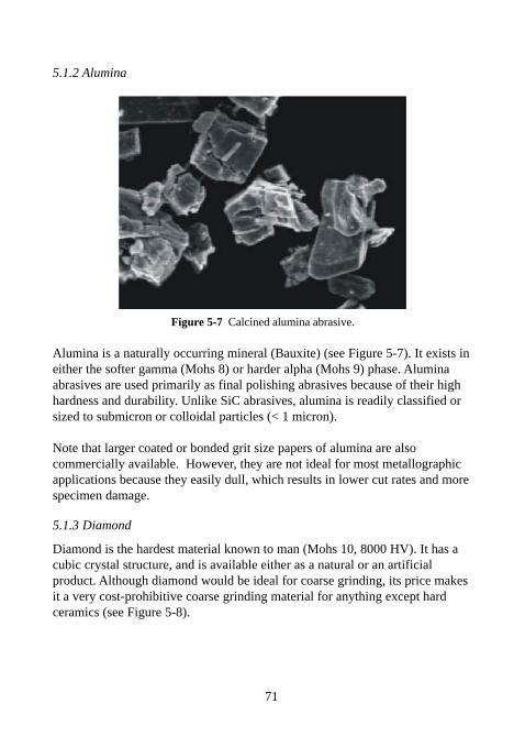
71
5.1.2 Alumina
Figure 5-7 Calcined alumina abrasive.
Alumina is a naturally occurring mineral (Bauxite) (see Figure 5-7). It exists ineither the softer gamma (Mohs 8) or harder alpha (Mohs 9) phase. Aluminaabrasives are used primarily as final polishing abrasives because of their highhardness and durability. Unlike SiC abrasives, alumina is readily classified orsized to submicron or colloidal particles (< 1 micron).
Note that larger coated or bonded grit size papers of alumina are alsocommercially available. However, they are not ideal for most metallographicapplications because they easily dull, which results in lower cut rates and morespecimen damage.
5.1.3 Diamond
Diamond is the hardest material known to man (Mohs 10, 8000 HV). It has acubic crystal structure, and is available either as a natural or an artificialproduct. Although diamond would be ideal for coarse grinding, its price makesit a very cost-prohibitive coarse grinding material for anything except hardceramics (see Figure 5-8).
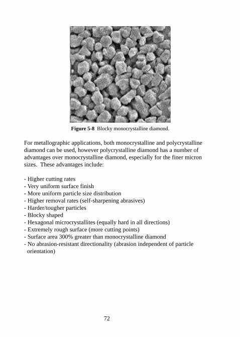
72
Figure 5-8 Blocky monocrystalline diamond.
For metallographic applications, both monocrystalline and polycrystallinediamond can be used, however polycrystalline diamond has a number ofadvantages over monocrystalline diamond, especially for the finer micronsizes. These advantages include:
- Higher cutting rates- Very uniform surface finish- More uniform particle size distribution- Higher removal rates (self-sharpening abrasives)- Harder/tougher particles- Blocky shaped- Hexagonal microcrystallites (equally hard in all directions)- Extremely rough surface (more cutting points)- Surface area 300% greater than monocrystalline diamond- No abrasion-resistant directionality (abrasion independent of particle orientation)
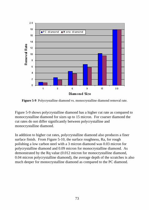
73
Figure 5-9 Polycrystalline diamond vs. monocrystalline diamond removal rate.
Figure 5-9 shows polycrystalline diamond has a higher cut rate as compared tomonocrystalline diamond for sizes up to 15 micron. For coarser diamond thecut rates do not differ significantly between polycrystalline andmonocrystalline diamond.
In addition to higher cut rates, polycrystalline diamond also produces a finersurface finish. From Figure 5-10, the surface roughness, Ra, for roughpolishing a low carbon steel with a 3 micron diamond was 0.03 micron forpolycrystalline diamond and 0.09 micron for monocrystalline diamond. Asdemonstrated by the Rq value (0.012 micron for monocrystalline diamond,0.04 micron polycrystalline diamond), the average depth of the scratches is alsomuch deeper for monocrystalline diamond as compared to the PC diamond.
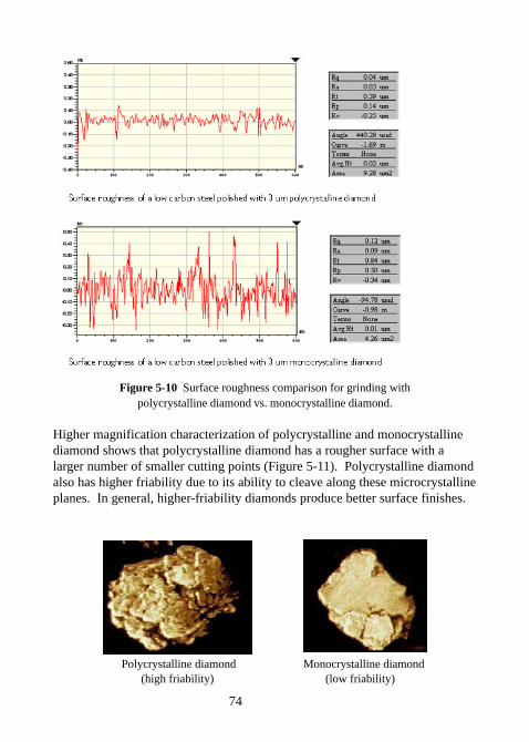
74
Figure 5-10 Surface roughness comparison for grinding withpolycrystalline diamond vs. monocrystalline diamond.
Higher magnification characterization of polycrystalline and monocrystallinediamond shows that polycrystalline diamond has a rougher surface with alarger number of smaller cutting points (Figure 5-11). Polycrystalline diamondalso has higher friability due to its ability to cleave along these microcrystallineplanes. In general, higher-friability diamonds produce better surface finishes.
Polycrystalline diamond Monocrystalline diamond (high friability) (low friability)
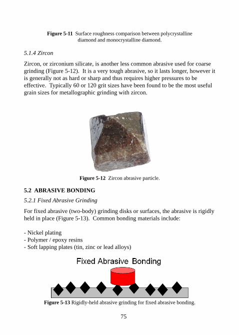
75
Figure 5-11 Surface roughness comparison between polycrystallinediamond and monocrystalline diamond.
5.1.4 Zircon
Zircon, or zirconium silicate, is another less common abrasive used for coarsegrinding (Figure 5-12). It is a very tough abrasive, so it lasts longer, however itis generally not as hard or sharp and thus requires higher pressures to beeffective. Typically 60 or 120 grit sizes have been found to be the most usefulgrain sizes for metallographic grinding with zircon.
Figure 5-12 Zircon abrasive particle.
5.2 ABRASIVE BONDING
5.2.1 Fixed Abrasive Grinding
For fixed abrasive (two-body) grinding disks or surfaces, the abrasive is rigidlyheld in place (Figure 5-13). Common bonding materials include:
- Nickel plating- Polymer / epoxy resins- Soft lapping plates (tin, zinc or lead alloys)
Figure 5-13 Rigidly-held abrasive grinding for fixed abrasive bonding.
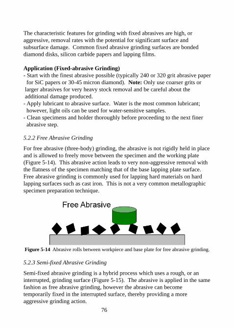
76
The characteristic features for grinding with fixed abrasives are high, oraggressive, removal rates with the potential for significant surface andsubsurface damage. Common fixed abrasive grinding surfaces are bondeddiamond disks, silicon carbide papers and lapping films.
Application (Fixed-abrasive Grinding)- Start with the finest abrasive possible (typically 240 or 320 grit abrasive paper for SiC papers or 30-45 micron diamond). Note: Only use coarser grits or larger abrasives for very heavy stock removal and be careful about the additional damage produced.- Apply lubricant to abrasive surface. Water is the most common lubricant; however, light oils can be used for water-sensitive samples.- Clean specimens and holder thoroughly before proceeding to the next finer abrasive step.
5.2.2 Free Abrasive Grinding
For free abrasive (three-body) grinding, the abrasive is not rigidly held in placeand is allowed to freely move between the specimen and the working plate(Figure 5-14). This abrasive action leads to very non-aggressive removal withthe flatness of the specimen matching that of the base lapping plate surface.Free abrasive grinding is commonly used for lapping hard materials on hardlapping surfaces such as cast iron. This is not a very common metallographicspecimen preparation technique.
Figure 5-14 Abrasive rolls between workpiece and base plate for free abrasive grinding.
5.2.3 Semi-fixed Abrasive Grinding
Semi-fixed abrasive grinding is a hybrid process which uses a rough, or aninterrupted, grinding surface (Figure 5-15). The abrasive is applied in the samefashion as free abrasive grinding, however the abrasive can becometemporarily fixed in the interrupted surface, thereby providing a moreaggressive grinding action.
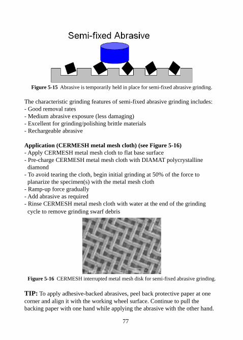
77
Figure 5-15 Abrasive is temporarily held in place for semi-fixed abrasive grinding.
The characteristic grinding features of semi-fixed abrasive grinding includes:- Good removal rates- Medium abrasive exposure (less damaging)- Excellent for grinding/polishing brittle materials- Rechargeable abrasive
Application (CERMESH metal mesh cloth) (see Figure 5-16)- Apply CERMESH metal mesh cloth to flat base surface- Pre-charge CERMESH metal mesh cloth with DIAMAT polycrystalline diamond- To avoid tearing the cloth, begin initial grinding at 50% of the force to planarize the specimen(s) with the metal mesh cloth- Ramp-up force gradually- Add abrasive as required- Rinse CERMESH metal mesh cloth with water at the end of the grinding cycle to remove grinding swarf debris
Figure 5-16 CERMESH interrupted metal mesh disk for semi-fixed abrasive grinding.
TIP: To apply adhesive-backed abrasives, peel back protective paper at onecorner and align it with the working wheel surface. Continue to pull thebacking paper with one hand while applying the abrasive with the other hand.
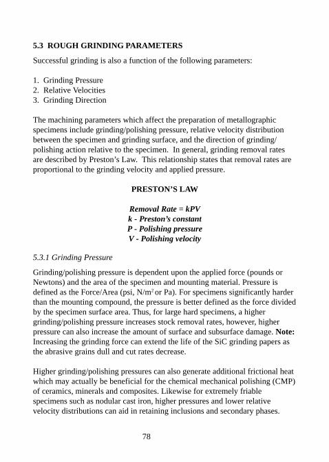
78
5.3 ROUGH GRINDING PARAMETERS
Successful grinding is also a function of the following parameters:
1. Grinding Pressure2. Relative Velocities3. Grinding Direction
The machining parameters which affect the preparation of metallographicspecimens include grinding/polishing pressure, relative velocity distributionbetween the specimen and grinding surface, and the direction of grinding/polishing action relative to the specimen. In general, grinding removal ratesare described by Preston’s Law. This relationship states that removal rates areproportional to the grinding velocity and applied pressure.
PRESTON’S LAW
Removal Rate = kPVk - Preston’s constantP - Polishing pressureV - Polishing velocity
5.3.1 Grinding Pressure
Grinding/polishing pressure is dependent upon the applied force (pounds orNewtons) and the area of the specimen and mounting material. Pressure isdefined as the Force/Area (psi, N/m2 or Pa). For specimens significantly harderthan the mounting compound, the pressure is better defined as the force dividedby the specimen surface area. Thus, for large hard specimens, a highergrinding/polishing pressure increases stock removal rates, however, higherpressure can also increase the amount of surface and subsurface damage. Note:Increasing the grinding force can extend the life of the SiC grinding papers asthe abrasive grains dull and cut rates decrease.
Higher grinding/polishing pressures can also generate additional frictional heatwhich may actually be beneficial for the chemical mechanical polishing (CMP)of ceramics, minerals and composites. Likewise for extremely friablespecimens such as nodular cast iron, higher pressures and lower relativevelocity distributions can aid in retaining inclusions and secondary phases.
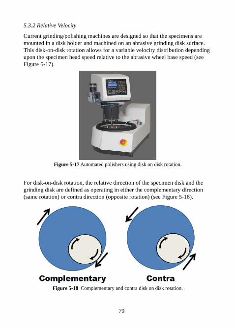
79
5.3.2 Relative Velocity
Current grinding/polishing machines are designed so that the specimens aremounted in a disk holder and machined on an abrasive grinding disk surface.This disk-on-disk rotation allows for a variable velocity distribution dependingupon the specimen head speed relative to the abrasive wheel base speed (seeFigure 5-17).
Figure 5-17 Automated polishers using disk on disk rotation.
For disk-on-disk rotation, the relative direction of the specimen disk and thegrinding disk are defined as operating in either the complementary direction(same rotation) or contra direction (opposite rotation) (see Figure 5-18).
Figure 5-18 Complementary and contra disk on disk rotation.
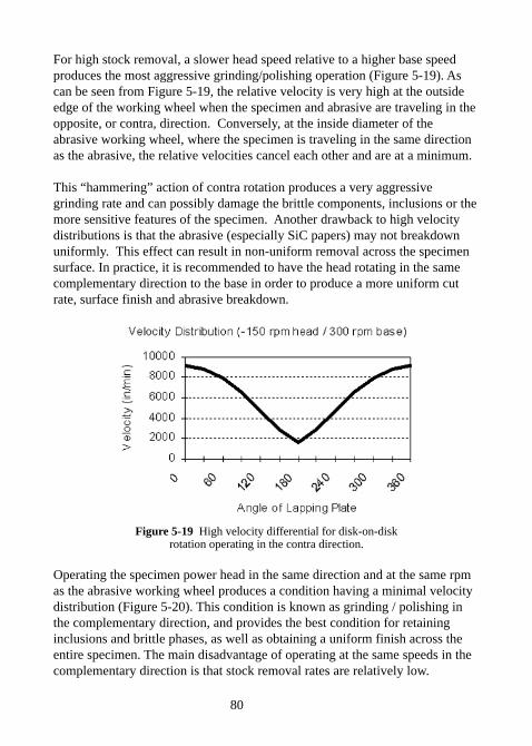
80
For high stock removal, a slower head speed relative to a higher base speedproduces the most aggressive grinding/polishing operation (Figure 5-19). Ascan be seen from Figure 5-19, the relative velocity is very high at the outsideedge of the working wheel when the specimen and abrasive are traveling in theopposite, or contra, direction. Conversely, at the inside diameter of theabrasive working wheel, where the specimen is traveling in the same directionas the abrasive, the relative velocities cancel each other and are at a minimum.
This “hammering” action of contra rotation produces a very aggressivegrinding rate and can possibly damage the brittle components, inclusions or themore sensitive features of the specimen. Another drawback to high velocitydistributions is that the abrasive (especially SiC papers) may not breakdownuniformly. This effect can result in non-uniform removal across the specimensurface. In practice, it is recommended to have the head rotating in the samecomplementary direction to the base in order to produce a more uniform cutrate, surface finish and abrasive breakdown.
Figure 5-19 High velocity differential for disk-on-diskrotation operating in the contra direction.
Operating the specimen power head in the same direction and at the same rpmas the abrasive working wheel produces a condition having a minimal velocitydistribution (Figure 5-20). This condition is known as grinding / polishing inthe complementary direction, and provides the best condition for retaininginclusions and brittle phases, as well as obtaining a uniform finish across theentire specimen. The main disadvantage of operating at the same speeds in thecomplementary direction is that stock removal rates are relatively low.
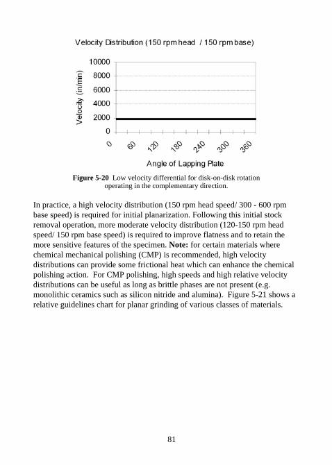
81
Figure 5-20 Low velocity differential for disk-on-disk rotationoperating in the complementary direction.
In practice, a high velocity distribution (150 rpm head speed/ 300 - 600 rpmbase speed) is required for initial planarization. Following this initial stockremoval operation, more moderate velocity distribution (120-150 rpm headspeed/ 150 rpm base speed) is required to improve flatness and to retain themore sensitive features of the specimen. Note: for certain materials wherechemical mechanical polishing (CMP) is recommended, high velocitydistributions can provide some frictional heat which can enhance the chemicalpolishing action. For CMP polishing, high speeds and high relative velocitydistributions can be useful as long as brittle phases are not present (e.g.monolithic ceramics such as silicon nitride and alumina). Figure 5-21 shows arelative guidelines chart for planar grinding of various classes of materials.
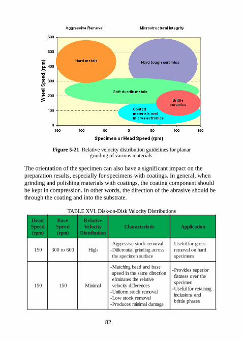
82
Figure 5-21 Relative velocity distribution guidelines for planargrinding of various materials.
The orientation of the specimen can also have a significant impact on thepreparation results, especially for specimens with coatings. In general, whengrinding and polishing materials with coatings, the coating component shouldbe kept in compression. In other words, the direction of the abrasive should bethrough the coating and into the substrate.
TABLE XVI. Disk-on-Disk Velocity Distributions
daeHdeepS)mpr(
esaBdeepS)mpr(
evitaleRyticoleV
noitubirtsiDcitsiretcarahC noitacilppA
051 006ot003 hgiHlavomerkcotsevisserggA-ssorcagnidnirglaitnereffiD-
ecafrusnemicepseht
ssorgroflufesU-drahnolavomer
snemiceps
051 051 laminiM
esabdnadaehgnihctaM-noitceridemasehtnideeps
evitalerehtsetanimilesecnereffidyticolev
lavomerkcotsmrofinU-lavomerkcotswoL-
egamadlaminimsecudorP-
roirepussedivorP-ehtrevossentalf
nemicepsgniniaterroflufesU-
dnasnoisulcnisesahpelttirb
83
5.4 PLANAR GRINDING (ROUGH GRINDING)
The best time-tested method for rough grinding metals, plastics, rubber andsofter composite materials is using SiC abrasive grinding papers. Othertechniques have been used; however, they typically are very expensive andrequire too much maintenance for these types of materials. SiC abrasive papersfit into a class of grinding known as fixed abrasive grinding.
5.4.1 Soft Nonferrous Metals
It is recommended that the initial grinding of soft nonferrous metals be donewith 320 grit SiC abrasive paper followed by 400, 600, 800 and 1200 grit SiCpapers. Since these materials are relatively soft, they do not easily break downthe SiC paper; therefore, initial grinding with 320 grit is generally sufficient forminimizing initial deformation while maintaining good removal rates. Forextremely soft, low recrystallization metals such as tin, lead and zinc, it is alsorecommended that alumina papers or lapping films be used to reduce thetendency of the abrasive from getting embedded into the soft specimen. This isbecause alumina abrasives are tougher then SiC abrasives and therefore do notfracture as easily.
5.4.2 Soft Ferrous Metals
Soft ferrous metals are relatively easy to grind with the depth of deformationbeing a major consideration. Using 240 grit SiC abrasives provides a goodinitial start, with the subsequent use of 320, 400, 600, 800 and 1200 grit SiCpapers.
5.4.3 Hard Ferrous Metals
Harder ferrous metals require more aggressive abrasives to achieve adequatematerial removal. Thus, coarse SiC abrasives (120 or 180 grit) arerecommended for stock removal requirements. Once planarity and the area ofinterest are obtained, a standard 240, 320, 400 and 600 grit series isrecommended.
5.4.4 Super Alloys and Hard Nonferrous Alloys
Hard nonferrous metals such as titanium are relatively easy to grind with SiCpapers. Depending upon the initial condition of the specimen, grinding with240, 320, 400, 600, 800 and 1200 grit papers will produce excellent results.
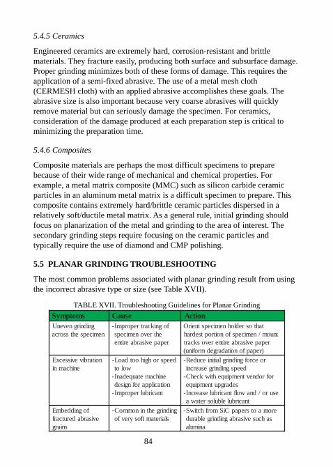
84
5.4.5 Ceramics
Engineered ceramics are extremely hard, corrosion-resistant and brittlematerials. They fracture easily, producing both surface and subsurface damage.Proper grinding minimizes both of these forms of damage. This requires theapplication of a semi-fixed abrasive. The use of a metal mesh cloth(CERMESH cloth) with an applied abrasive accomplishes these goals. Theabrasive size is also important because very coarse abrasives will quicklyremove material but can seriously damage the specimen. For ceramics,consideration of the damage produced at each preparation step is critical tominimizing the preparation time.
5.4.6 Composites
Composite materials are perhaps the most difficult specimens to preparebecause of their wide range of mechanical and chemical properties. Forexample, a metal matrix composite (MMC) such as silicon carbide ceramicparticles in an aluminum metal matrix is a difficult specimen to prepare. Thiscomposite contains extremely hard/brittle ceramic particles dispersed in arelatively soft/ductile metal matrix. As a general rule, initial grinding shouldfocus on planarization of the metal and grinding to the area of interest. Thesecondary grinding steps require focusing on the ceramic particles andtypically require the use of diamond and CMP polishing.
5.5 PLANAR GRINDING TROUBLESHOOTING
The most common problems associated with planar grinding result from usingthe incorrect abrasive type or size (see Table XVII).
TABLE XVII. Troubleshooting Guidelines for Planar Grinding
smotpmyS esuaC noitcAgnidnirgnevenU
nemicepsehtssorcafognikcartreporpmI-
ehtrevonemicepsrepapevisarbaeritne
tahtosredlohnemicepstneirOtnuom/nemicepsfonoitroptsedrah
repapevisarbaeritnerevoskcart)repapfonoitadargedmrofinu(
noitarbivevissecxEenihcamni
deepsrohgihootdaoL-wolot
enihcametauqedanI-noitacilpparofngised
tnacirbulreporpmI-
roecrofgnidnirglaitiniecudeR-deepsgnidnirgesaercni
rofrodnevtnempiuqehtiwkcehC-sedargputnempiuqe
esuro/dnawolftnacirbulesaercnI-tnacirbulelbulosretawa
fogniddebmEevisarbaderutcarf
sniarg
gnidnirgehtninommoC-slairetamtfosyrevfo
eromaotsrepapCiSmorfhctiwS-sahcusevisarbagnidnirgelbarud
animula
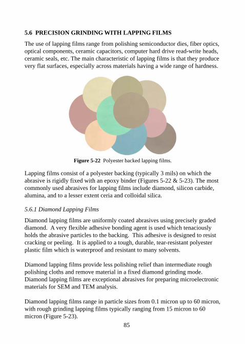
85
5.6 PRECISION GRINDING WITH LAPPING FILMS
The use of lapping films range from polishing semiconductor dies, fiber optics,optical components, ceramic capacitors, computer hard drive read-write heads,ceramic seals, etc. The main characteristic of lapping films is that they producevery flat surfaces, especially across materials having a wide range of hardness.
Figure 5-22 Polyester backed lapping films.
Lapping films consist of a polyester backing (typically 3 mils) on which theabrasive is rigidly fixed with an epoxy binder (Figures 5-22 & 5-23). The mostcommonly used abrasives for lapping films include diamond, silicon carbide,alumina, and to a lesser extent ceria and colloidal silica.
5.6.1 Diamond Lapping Films
Diamond lapping films are uniformly coated abrasives using precisely gradeddiamond. A very flexible adhesive bonding agent is used which tenaciouslyholds the abrasive particles to the backing. This adhesive is designed to resistcracking or peeling. It is applied to a tough, durable, tear-resistant polyesterplastic film which is waterproof and resistant to many solvents.
Diamond lapping films provide less polishing relief than intermediate roughpolishing cloths and remove material in a fixed diamond grinding mode.Diamond lapping films are exceptional abrasives for preparing microelectronicmaterials for SEM and TEM analysis.
Diamond lapping films range in particle sizes from 0.1 micron up to 60 micron,with rough grinding lapping films typically ranging from 15 micron to 60micron (Figure 5-23).
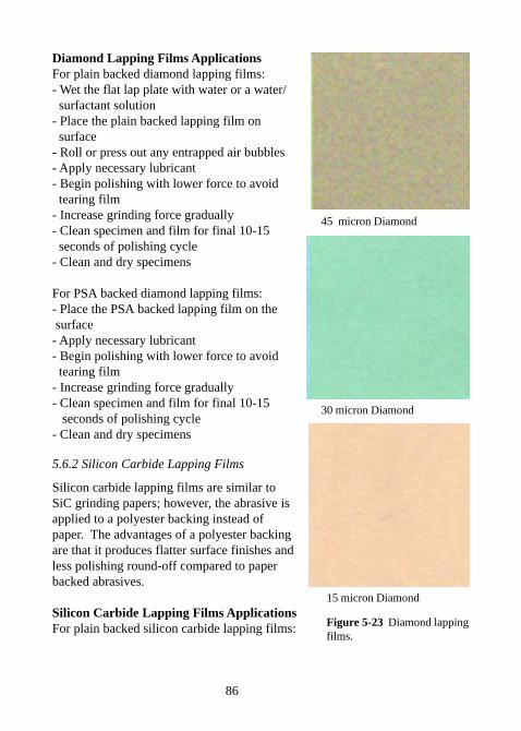
86
15 micron Diamond
Figure 5-23 Diamond lappingfilms.
30 micron Diamond
45 micron Diamond
Diamond Lapping Films ApplicationsFor plain backed diamond lapping films:- Wet the flat lap plate with water or a water/ surfactant solution- Place the plain backed lapping film on surface- Roll or press out any entrapped air bubbles- Apply necessary lubricant- Begin polishing with lower force to avoid tearing film- Increase grinding force gradually- Clean specimen and film for final 10-15 seconds of polishing cycle- Clean and dry specimens
For PSA backed diamond lapping films:- Place the PSA backed lapping film on the surface- Apply necessary lubricant- Begin polishing with lower force to avoid tearing film- Increase grinding force gradually- Clean specimen and film for final 10-15 seconds of polishing cycle- Clean and dry specimens
5.6.2 Silicon Carbide Lapping Films
Silicon carbide lapping films are similar toSiC grinding papers; however, the abrasive isapplied to a polyester backing instead ofpaper. The advantages of a polyester backingare that it produces flatter surface finishes andless polishing round-off compared to paperbacked abrasives.
Silicon Carbide Lapping Films ApplicationsFor plain backed silicon carbide lapping films:
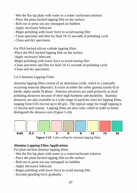
87
- Wet the flat lap plate with water or a water/ surfactant solution- Place the plain backed lapping film on the surface- Roll out or press out any entrapped air bubbles- Apply necessary lubricant- Begin polishing with lower force to avoid tearing film- Clean specimen and film for final 10-15 seconds of polishing cycle- Clean and dry specimens
For PSA backed silicon carbide lapping films-Place the PSA backed lapping film on the surface-Apply necessary lubricant-Begin polishing with lower force to avoid tearing film-Clean specimen and film for final 10-15 seconds of polishing cycle-Clean and dry specimens
5.6.3 Alumina Lapping Films
Alumina lapping films consist of an aluminum oxide, which is a naturallyoccurring material (Bauxite). It exists in either the softer gamma (mohs 8) orharder alpha (mohs 9) phase. Alumina abrasives are used primarily as finalpolishing abrasives because of their high hardness and durability. Aluminaabrasives are also available in a wide range of particles sizes for lapping films,ranging from 0.05 micron up to 60 grit. The typical range for rough lapping is12 micron and coarser. Lapping films are also color coded in order to betterdistinguish the abrasive size (Figure 5-24).
Figure 5-24 Color coding for alumina lapping films.
Alumina Lapping Films ApplicationsFor plain backed alumina lapping films:- Wet the flat lap plate with water or a water/surfactant solution- Place the plain backed lapping film on the surface- Roll out or press out any entrapped air bubbles- Apply necessary lubricant- Begin polishing with lower force to avoid tearing film- Increase grinding force gradually
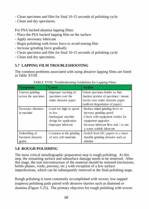
88
- Clean specimen and film for final 10-15 seconds of polishing cycle- Clean and dry specimens.
For PSA backed alumina lapping films:- Place the PSA backed lapping film on the surface- Apply necessary lubricant- Begin polishing with lower force to avoid tearing film- Increase grinding force gradually- Clean specimen and film for final 10-15 seconds of polishing cycle- Clean and dry specimens.
5.7 LAPPING FILM TROUBLESHOOTING
The common problems associated with using abrasive lapping films are listedin Table XVIII.
TABLE XVIII. Troubleshooting Guidelines for Lapping Films
smotpmyS esuaC noitcAgnidnirgnevenU
nemicepsehtssorcafognikcartreporpmI-
ehtrevonemicepsrepapevisarbaeritne
tahtosredlohnemicepstneirOtnuom/nemicepsfonoitroptsedrah
repapevisarbaeritnerevoskcart)repapfonoitadargedmrofinu(
noitarbivevissecxEenihcamni
deepsrohgihootdaoL-wolot
enihcametauqedanI-noitacilpparofngised
tnacirbulreporpmI-
roecrofgnidnirglaitiniecudeR-deepsgnidnirgesaercni
rofrodnevtnempiuqehtiwkcehC-sedargputnempiuqe
esuro/dnawolftnacirbulesaercnI-tnacirbulelbulosretawa
fogniddebmEevisarbaderutcarf
sniarg
gnidnirgehtninommoC-slairetamtfosyrevfo
eromaotsrepapCiSmorfhctiwS-sahcusevisarbagnidnirgelbarud
animula
5.8 ROUGH POLISHING
The most critical metallographic preparation step is rough polishing. At thisstep, the remaining surface and subsurface damage needs to be removed. Afterthis stage, the true microstructure of the material should be restored (inclusions,brittle phases, voids, porosity, etc.) with exception of a few surfaceimperfections, which can be subsequently removed at the final polishing stage.
Rough polishing is most commonly accomplished with woven, low napped(napless) polishing pads paired with abrasive slurries such as diamond oralumina (Figure 5-25). The primary objective for rough polishing with woven
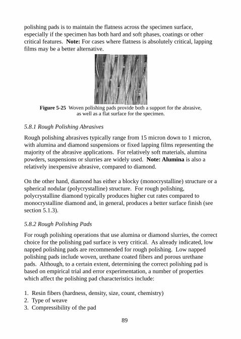
89
polishing pads is to maintain the flatness across the specimen surface,especially if the specimen has both hard and soft phases, coatings or othercritical features. Note: For cases where flatness is absolutely critical, lappingfilms may be a better alternative.
Figure 5-25 Woven polishing pads provide both a support for the abrasive,as well as a flat surface for the specimen.
5.8.1 Rough Polishing Abrasives
Rough polishing abrasives typically range from 15 micron down to 1 micron,with alumina and diamond suspensions or fixed lapping films representing themajority of the abrasive applications. For relatively soft materials, aluminapowders, suspensions or slurries are widely used. Note: Alumina is also arelatively inexpensive abrasive, compared to diamond.
On the other hand, diamond has either a blocky (monocrystalline) structure or aspherical nodular (polycrystalline) structure. For rough polishing,polycrystalline diamond typically produces higher cut rates compared tomonocrystalline diamond and, in general, produces a better surface finish (seesection 5.1.3).
5.8.2 Rough Polishing Pads
For rough polishing operations that use alumina or diamond slurries, the correctchoice for the polishing pad surface is very critical. As already indicated, lownapped polishing pads are recommended for rough polishing. Low nappedpolishing pads include woven, urethane coated fibers and porous urethanepads. Although, to a certain extent, determining the correct polishing pad isbased on empirical trial and error experimentation, a number of propertieswhich affect the polishing pad characteristics include:
1. Resin fibers (hardness, density, size, count, chemistry)2. Type of weave3. Compressibility of the pad
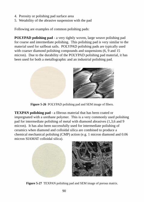
90
4. Porosity or polishing pad surface area5. Wetability of the abrasive suspension with the pad
Following are examples of common polishing pads:
POLYPAD polishing pad - a very tightly woven, large weave polishing padfor coarse and intermediate polishing. This polishing pad is very similar to thematerial used for sailboat sails. POLYPAD polishing pads are typically usedwith coarser diamond polishing compounds and suspensions (6, 9 and 15micron). Due to the durability of the POLYPAD polishing pad material, it hasbeen used for both a metallographic and an industrial polishing pad.
Figure 5-26 POLYPAD polishing pad and SEM image of fibers.
TEXPAN polishing pad - a fibrous material that has been coated orimpregnated with a urethane polymer. This is a very commonly used polishingpad for intermediate polishing of metal with diamond abrasives (1,3,6 and 9micron). It has also been successfully used for intermediate polishing ofceramics when diamond and colloidal silica are combined to produce achemical mechanical polishing (CMP) action (e.g. 1 micron diamond and 0.06micron SIAMAT colloidal silica).
Figure 5-27 TEXPAN polishing pad and SEM image of porous matrix.
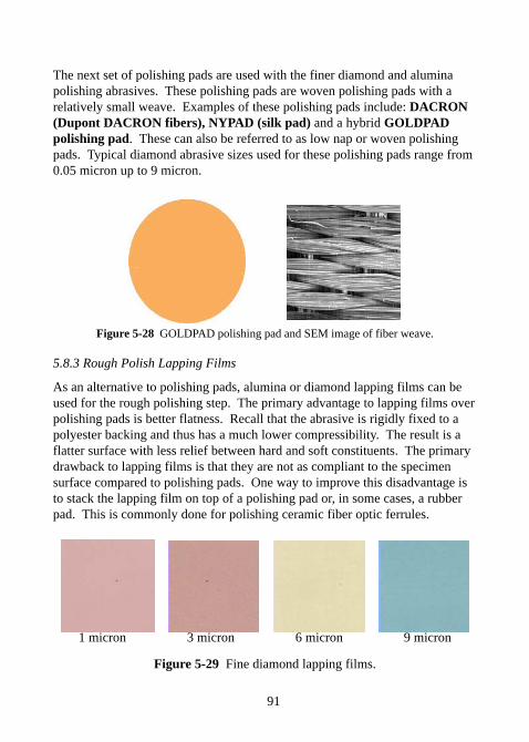
91
The next set of polishing pads are used with the finer diamond and aluminapolishing abrasives. These polishing pads are woven polishing pads with arelatively small weave. Examples of these polishing pads include: DACRON(Dupont DACRON fibers), NYPAD (silk pad) and a hybrid GOLDPADpolishing pad. These can also be referred to as low nap or woven polishingpads. Typical diamond abrasive sizes used for these polishing pads range from0.05 micron up to 9 micron.
Figure 5-28 GOLDPAD polishing pad and SEM image of fiber weave.
5.8.3 Rough Polish Lapping Films
As an alternative to polishing pads, alumina or diamond lapping films can beused for the rough polishing step. The primary advantage to lapping films overpolishing pads is better flatness. Recall that the abrasive is rigidly fixed to apolyester backing and thus has a much lower compressibility. The result is aflatter surface with less relief between hard and soft constituents. The primarydrawback to lapping films is that they are not as compliant to the specimensurface compared to polishing pads. One way to improve this disadvantage isto stack the lapping film on top of a polishing pad or, in some cases, a rubberpad. This is commonly done for polishing ceramic fiber optic ferrules.
1 micron 3 micron 6 micron 9 micron
Figure 5-29 Fine diamond lapping films.
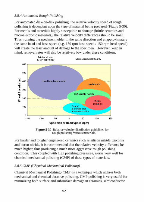
92
5.8.4 Automated Rough Polishing
For automated disk-on-disk polishing, the relative velocity speed of roughpolishing is dependent upon the type of material being prepared (Figure 5-30).For metals and materials highly susceptible to damage (brittle ceramics andmicroelectronic materials), the relative velocity differences should be small.Thus, running the specimen holder in the same direction and at approximatelythe same head and base speed (e.g. 150 rpm base speed / 150 rpm head speed)will create the least amount of damage to the specimen. However, keep inmind, removal rates will also be relatively low under these conditions.
Figure 5-30 Relative velocity distribution guidelines for rough polishing various materials.
For harder and tougher engineered ceramics such as silicon nitride, zirconiaand boron nitride, it is recommended that the relative velocity difference bemuch higher, thus producing a much more aggressive rough polishingcondition. This coupled with high polishing pressures, works very well forchemical mechanical polishing (CMP) of these types of materials.
5.8.5 CMP (Chemical Mechanical Polishing)
Chemical Mechanical Polishing (CMP) is a technique which utilizes bothmechanical and chemical abrasive polishing. CMP polishing is very useful forminimizing both surface and subsurface damage in ceramics, semiconductor
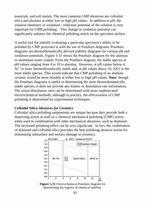
93
materials, and soft metals. The most common CMP abrasives are colloidalsilica and alumina at either low or high pH values. In addition to pH, thesolution chemistry or oxidation / reduction potential of the solution is veryimportant for CMP polishing. This change in oxidation potential cansignificantly enhance the chemical polishing attack on the specimen surface.
A useful tool for initially evaluating a particular specimen’s ability to bepolished by CMP processes is with the use of Pourbaix diagrams. Pourbaixdiagrams are thermodynamically derived stability diagrams for various pH andoxidation potentials. Figure 5-31 shows the Pourbaix diagram for the aluminaor aluminum-water system. From the Pourbaix diagram, the stable species atpH values ranging from 4 to 10 is alumina. However, at pH values below 4,Al+3 is more thermodynamically stable and, at pH values above 10, AlO2- is themost stable species. This would indicate that CMP polishing of an aluminaceramic would be more feasible at either low or high pH values. Note: thoughthe Pourbaix diagrams is useful in determining the most thermodynamicallystable species, it does not provide any kinetic or dissolution rate information.The actual dissolution rates can be determined with more sophisticatedelectrochemical methods, although in practice, the effectiveness of CMPpolishing is determined by experimental techniques.
Colloidal Silica Abrasives for CeramicsColloidal silica polishing suspensions are unique because they provide both adispersing action as well as a chemical mechanical polishing (CMP) actionwhen used in combination with other mechanical abrasives, such as diamond.The increased polishing effect can be very significant. In fact, the combinationof diamond and colloidal silica provides the best polishing abrasive action foreliminating subsurface and surface damage in ceramics.
Figure 5-31 Electrochemical Pourbaix diagram fordetermining the regions of chemical stability.
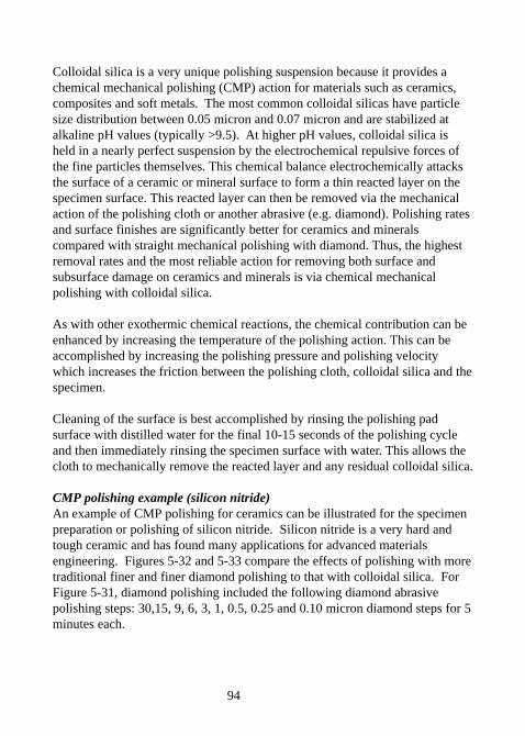
94
Colloidal silica is a very unique polishing suspension because it provides achemical mechanical polishing (CMP) action for materials such as ceramics,composites and soft metals. The most common colloidal silicas have particlesize distribution between 0.05 micron and 0.07 micron and are stabilized atalkaline pH values (typically >9.5). At higher pH values, colloidal silica isheld in a nearly perfect suspension by the electrochemical repulsive forces ofthe fine particles themselves. This chemical balance electrochemically attacksthe surface of a ceramic or mineral surface to form a thin reacted layer on thespecimen surface. This reacted layer can then be removed via the mechanicalaction of the polishing cloth or another abrasive (e.g. diamond). Polishing ratesand surface finishes are significantly better for ceramics and mineralscompared with straight mechanical polishing with diamond. Thus, the highestremoval rates and the most reliable action for removing both surface andsubsurface damage on ceramics and minerals is via chemical mechanicalpolishing with colloidal silica.
As with other exothermic chemical reactions, the chemical contribution can beenhanced by increasing the temperature of the polishing action. This can beaccomplished by increasing the polishing pressure and polishing velocitywhich increases the friction between the polishing cloth, colloidal silica and thespecimen.
Cleaning of the surface is best accomplished by rinsing the polishing padsurface with distilled water for the final 10-15 seconds of the polishing cycleand then immediately rinsing the specimen surface with water. This allows thecloth to mechanically remove the reacted layer and any residual colloidal silica.
CMP polishing example (silicon nitride)An example of CMP polishing for ceramics can be illustrated for the specimenpreparation or polishing of silicon nitride. Silicon nitride is a very hard andtough ceramic and has found many applications for advanced materialsengineering. Figures 5-32 and 5-33 compare the effects of polishing with moretraditional finer and finer diamond polishing to that with colloidal silica. ForFigure 5-31, diamond polishing included the following diamond abrasivepolishing steps: 30,15, 9, 6, 3, 1, 0.5, 0.25 and 0.10 micron diamond steps for 5minutes each.
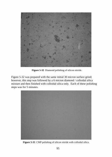
95
Figure 5-32 Diamond polishing of silicon nitride.
Figure 5-32 was prepared with the same initial 30 micron surface grind;however, this step was followed by a 6 micron diamond / colloidal silicamixture and then finished with colloidal silica only. Each of these polishingsteps was for 5 minutes.
Figure 5-33 CMP polishing of silicon nitride with colloidal silica.

96
As can be clearly observed, the use of colloidal silica significantly reduced thesubsurface and surface damage to the silicon nitride surface, whereas thediamond steps clearly did not remove the existing damage and only appears tohave propagated the initial damage.
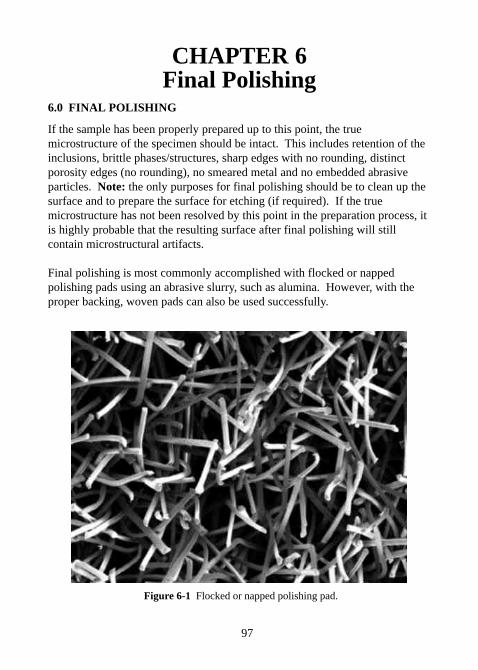
97
CHAPTER 6Final Polishing
6.0 FINAL POLISHING
If the sample has been properly prepared up to this point, the truemicrostructure of the specimen should be intact. This includes retention of theinclusions, brittle phases/structures, sharp edges with no rounding, distinctporosity edges (no rounding), no smeared metal and no embedded abrasiveparticles. Note: the only purposes for final polishing should be to clean up thesurface and to prepare the surface for etching (if required). If the truemicrostructure has not been resolved by this point in the preparation process, itis highly probable that the resulting surface after final polishing will stillcontain microstructural artifacts.
Final polishing is most commonly accomplished with flocked or nappedpolishing pads using an abrasive slurry, such as alumina. However, with theproper backing, woven pads can also be used successfully.
Figure 6-1 Flocked or napped polishing pad.
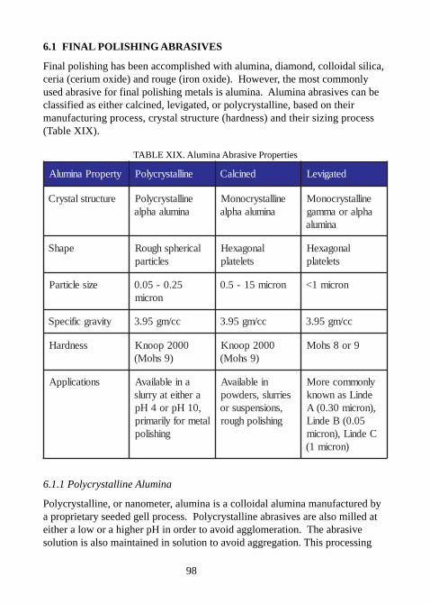
98
6.1 FINAL POLISHING ABRASIVES
Final polishing has been accomplished with alumina, diamond, colloidal silica,ceria (cerium oxide) and rouge (iron oxide). However, the most commonlyused abrasive for final polishing metals is alumina. Alumina abrasives can beclassified as either calcined, levigated, or polycrystalline, based on theirmanufacturing process, crystal structure (hardness) and their sizing process(Table XIX).
TABLE XIX. Alumina Abrasive Properties
ytreporPanimulA enillatsyrcyloP deniclaC detagiveL
erutcurtslatsyrC enillatsyrcyloPanimulaahpla
enillatsyrconoManimulaahpla
enillatsyrconoMahplaroammag
animula
epahS lacirehpshguoRselcitrap
lanogaxeHsteletalp
lanogaxeHsteletalp
eziselcitraP 52.0-50.0norcim
norcim51-5.0 norcim1<
ytivargcificepS cc/mg59.3 cc/mg59.3 cc/mg59.3
ssendraH 0002poonK)9shoM(
0002poonK)9shoM(
9ro8shoM
snoitacilppA anielbaliavAarehtietayrruls,01Hpro4Hp
latemrofyliramirpgnihsilop
nielbaliavAseirruls,sredwop
,snoisnepsusrognihsilophguor
ylnommoceroMedniLsanwonk
,)norcim03.0(A50.0(BedniL
CedniL,)norcim)norcim1(
6.1.1 Polycrystalline Alumina
Polycrystalline, or nanometer, alumina is a colloidal alumina manufactured bya proprietary seeded gell process. Polycrystalline abrasives are also milled ateither a low or a higher pH in order to avoid agglomeration. The abrasivesolution is also maintained in solution to avoid aggregation. This processing
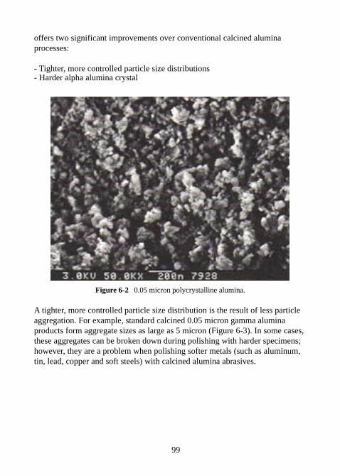
99
offers two significant improvements over conventional calcined aluminaprocesses:
- Tighter, more controlled particle size distributions- Harder alpha alumina crystal
Figure 6-2 0.05 micron polycrystalline alumina.
A tighter, more controlled particle size distribution is the result of less particleaggregation. For example, standard calcined 0.05 micron gamma aluminaproducts form aggregate sizes as large as 5 micron (Figure 6-3). In some cases,these aggregates can be broken down during polishing with harder specimens;however, they are a problem when polishing softer metals (such as aluminum,tin, lead, copper and soft steels) with calcined alumina abrasives.
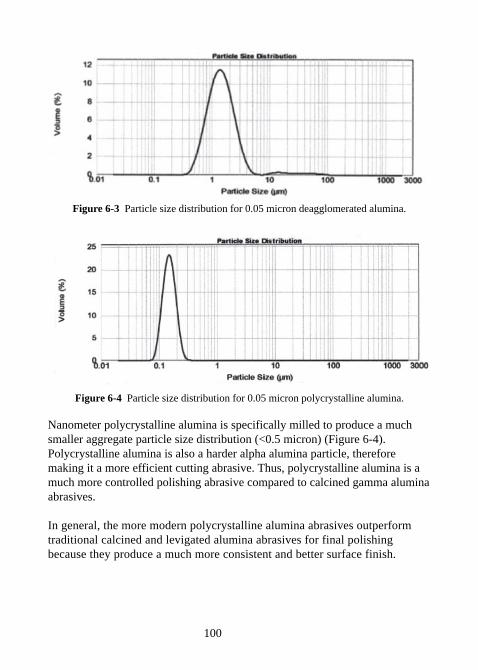
100
Figure 6-3 Particle size distribution for 0.05 micron deagglomerated alumina.
Figure 6-4 Particle size distribution for 0.05 micron polycrystalline alumina.
Nanometer polycrystalline alumina is specifically milled to produce a muchsmaller aggregate particle size distribution (<0.5 micron) (Figure 6-4).Polycrystalline alumina is also a harder alpha alumina particle, thereforemaking it a more efficient cutting abrasive. Thus, polycrystalline alumina is amuch more controlled polishing abrasive compared to calcined gamma aluminaabrasives.
In general, the more modern polycrystalline alumina abrasives outperformtraditional calcined and levigated alumina abrasives for final polishingbecause they produce a much more consistent and better surface finish.
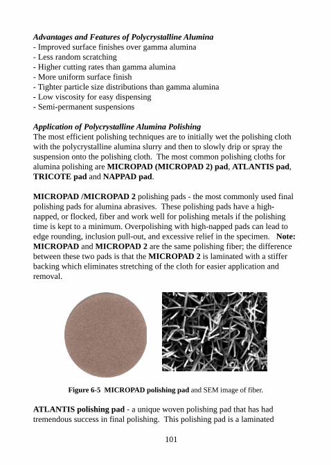
101
Advantages and Features of Polycrystalline Alumina- Improved surface finishes over gamma alumina- Less random scratching- Higher cutting rates than gamma alumina- More uniform surface finish- Tighter particle size distributions than gamma alumina- Low viscosity for easy dispensing- Semi-permanent suspensions
Application of Polycrystalline Alumina PolishingThe most efficient polishing techniques are to initially wet the polishing clothwith the polycrystalline alumina slurry and then to slowly drip or spray thesuspension onto the polishing cloth. The most common polishing cloths foralumina polishing are MICROPAD (MICROPAD 2) pad, ATLANTIS pad,TRICOTE pad and NAPPAD pad.
MICROPAD /MICROPAD 2 polishing pads - the most commonly used finalpolishing pads for alumina abrasives. These polishing pads have a high-napped, or flocked, fiber and work well for polishing metals if the polishingtime is kept to a minimum. Overpolishing with high-napped pads can lead toedge rounding, inclusion pull-out, and excessive relief in the specimen. Note:MICROPAD and MICROPAD 2 are the same polishing fiber; the differencebetween these two pads is that the MICROPAD 2 is laminated with a stifferbacking which eliminates stretching of the cloth for easier application andremoval.
Figure 6-5 MICROPAD polishing pad and SEM image of fiber.
ATLANTIS polishing pad - a unique woven polishing pad that has hadtremendous success in final polishing. This polishing pad is a laminated
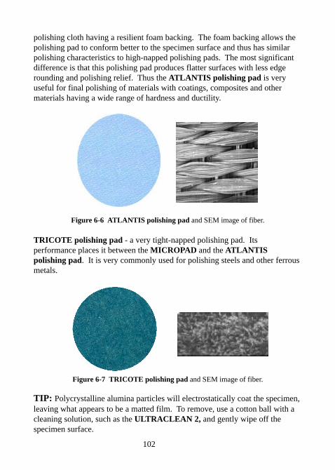
102
polishing cloth having a resilient foam backing. The foam backing allows thepolishing pad to conform better to the specimen surface and thus has similarpolishing characteristics to high-napped polishing pads. The most significantdifference is that this polishing pad produces flatter surfaces with less edgerounding and polishing relief. Thus the ATLANTIS polishing pad is veryuseful for final polishing of materials with coatings, composites and othermaterials having a wide range of hardness and ductility.
Figure 6-6 ATLANTIS polishing pad and SEM image of fiber.
TRICOTE polishing pad - a very tight-napped polishing pad. Itsperformance places it between the MICROPAD and the ATLANTISpolishing pad. It is very commonly used for polishing steels and other ferrousmetals.
Figure 6-7 TRICOTE polishing pad and SEM image of fiber.
TIP: Polycrystalline alumina particles will electrostatically coat the specimen,leaving what appears to be a matted film. To remove, use a cotton ball with acleaning solution, such as the ULTRACLEAN 2, and gently wipe off thespecimen surface.

103
6.1.2 Calcined Alumina Polishing Abrasives
Although polycrystalline alumina is the premium alumina polishing abrasive,calcined alumina abrasives have been used for many years for polishing a widerange of materials, and are still the most commonly used alumina polishingabrasives. The primary advantage of polishing with calcined alumina abrasivesover polycrystalline abrasives is cost. Typically, calcined abrasives are lessexpensive then polycrystalline abrasives and can be purchased in either apowder or slurry form.
Calcined alumina’s typically have a plate-like (platey) structure and areavailable in either the harder alpha or softer gamma crystal structure. Often,the very fine calcined products ( typically 1 micron or less) are jet milled toform a deagglomerated alumina powder. In general, deagglomerated calcinedalumina powders have a very high bulk density and are very “fluffy.”
Figure 6-8 Calcined alumina particles.
Application of Calcined Alumina PolishingCalcined alumina polishes are typically used on the same polishing pads aspolycrystalline alumina, e.g. MICROPAD, NAPPAD, ATLANTIS andTRICOTE. However, they are also commonly used with the MOLTEC 2polishing pad which is a very soft, canvas type of polishing pad. Likewise,MOLTEC 2 pad is a staple of the industry and is still a commonly usedpolishing pad with calcined alumina abrasives up to 5 microns in size.
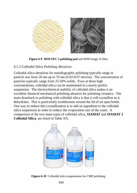
104
Figure 6-9 MOLTEC 2 polishing pad and SEM image of fiber.
6.1.3 Colloidal Silica Polishing Abrasives
Colloidal silica abrasives for metallographic polishing typically range inparticle size from 20 nm up to 70 nm (0.02-0.07 micron). The concentration ofparticles typically range from 25-50% solids. Even at these highconcentrations, colloidal silica can be maintained in a nearly perfectsuspension. The electrochemical stability of colloidal silica makes it anexcellent chemical mechanical polishing abrasive for polishing ceramics. Themain drawback to polishing with colloidal silica is that it will crystallize as itdehydrates. This is particularly troublesome around the lid of an open bottle.One way to reduce this crystallization is to add an ingredient to the colloidalsilica suspension in order to reduce the evaporation rate of the water. Acomparison of the two main types of colloidal silica, SIAMAT and SIAMAT 2Colloidal Silica, are listed in Table XX.
Figure 6-10 Colloidal silica suspensions for CMP polishing.
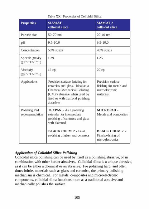
105
Table XX. Properties of Colloidal Silica
seitreporP TAMAISacilisladiolloc
2TAMAISacilisladiolloc
eziselcitraP mn07-05 mn04-02
Hp 0.01-5.9 0.01-5.9
noitartnecnoC sdilos%05 sdilos%04
ytivargcificepS)C°52/F°77@(
93.1 52.1
ytisocsiV)C°52/F°77@(
pc51 pc02
snoitacilppA rofgnihsinifecafrusnoisicerPasalaedI.ssalgdnascimarecgnihsiloPlacinahceMlacimehCybdesunehwevisarba)PMC(gnihsilopdnomaidhtiwroflesti
sevisarba
ecafrusnoisicerPdnaslatemrofgnihsinif
cinortceleorcimslairetam
daPgnihsiloPnoitadnemmocer
NAPXET gnihsilopasA-etaidemretnirofrednetxe
ssalgdnascimarecfognihsilopdnomaidhtiw
2MEHCKCALB laniF-scimarecdnassalgfognihsilop
DAPORCIM -setisopmocdnaslateM
2MEHCKCALB -fognihsiloplaniF
scinortceleorcim
Application of Colloidal Silica PolishingColloidal silica polishing can be used by itself as a polishing abrasive, or incombination with other harder abrasives. Colloidal silica is a unique abrasive,as it can be either a chemical or an abrasive. For polishing hard, and oftentimes brittle, materials such as glass and ceramics, the primary polishingmechanism is chemical. For metals, composites and microelectroniccomponents, colloidal silica functions more as a traditional abrasive andmechanically polishes the surface.
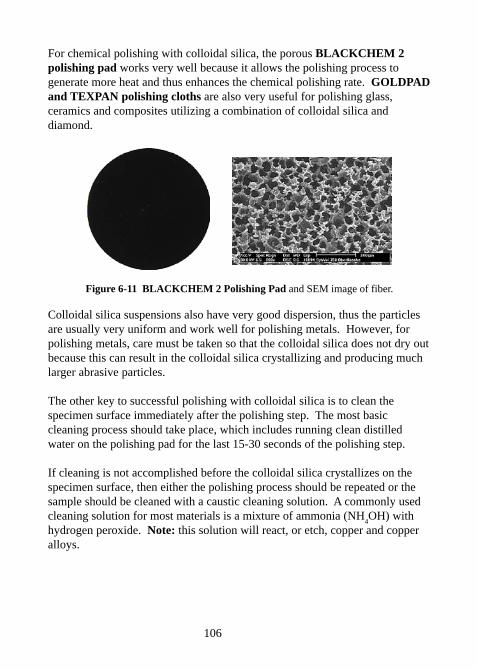
106
For chemical polishing with colloidal silica, the porous BLACKCHEM 2polishing pad works very well because it allows the polishing process togenerate more heat and thus enhances the chemical polishing rate. GOLDPADand TEXPAN polishing cloths are also very useful for polishing glass,ceramics and composites utilizing a combination of colloidal silica anddiamond.
Figure 6-11 BLACKCHEM 2 Polishing Pad and SEM image of fiber.
Colloidal silica suspensions also have very good dispersion, thus the particlesare usually very uniform and work well for polishing metals. However, forpolishing metals, care must be taken so that the colloidal silica does not dry outbecause this can result in the colloidal silica crystallizing and producing muchlarger abrasive particles.
The other key to successful polishing with colloidal silica is to clean thespecimen surface immediately after the polishing step. The most basiccleaning process should take place, which includes running clean distilledwater on the polishing pad for the last 15-30 seconds of the polishing step.
If cleaning is not accomplished before the colloidal silica crystallizes on thespecimen surface, then either the polishing process should be repeated or thesample should be cleaned with a caustic cleaning solution. A commonly usedcleaning solution for most materials is a mixture of ammonia (NH
4OH) with
hydrogen peroxide. Note: this solution will react, or etch, copper and copperalloys.
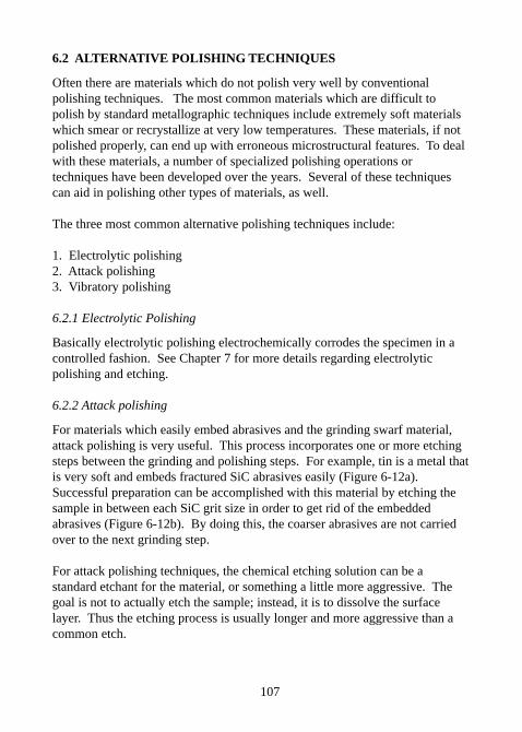
107
6.2 ALTERNATIVE POLISHING TECHNIQUES
Often there are materials which do not polish very well by conventionalpolishing techniques. The most common materials which are difficult topolish by standard metallographic techniques include extremely soft materialswhich smear or recrystallize at very low temperatures. These materials, if notpolished properly, can end up with erroneous microstructural features. To dealwith these materials, a number of specialized polishing operations ortechniques have been developed over the years. Several of these techniquescan aid in polishing other types of materials, as well.
The three most common alternative polishing techniques include:
1. Electrolytic polishing2. Attack polishing3. Vibratory polishing
6.2.1 Electrolytic Polishing
Basically electrolytic polishing electrochemically corrodes the specimen in acontrolled fashion. See Chapter 7 for more details regarding electrolyticpolishing and etching.
6.2.2 Attack polishing
For materials which easily embed abrasives and the grinding swarf material,attack polishing is very useful. This process incorporates one or more etchingsteps between the grinding and polishing steps. For example, tin is a metal thatis very soft and embeds fractured SiC abrasives easily (Figure 6-12a).Successful preparation can be accomplished with this material by etching thesample in between each SiC grit size in order to get rid of the embeddedabrasives (Figure 6-12b). By doing this, the coarser abrasives are not carriedover to the next grinding step.
For attack polishing techniques, the chemical etching solution can be astandard etchant for the material, or something a little more aggressive. Thegoal is not to actually etch the sample; instead, it is to dissolve the surfacelayer. Thus the etching process is usually longer and more aggressive than acommon etch.
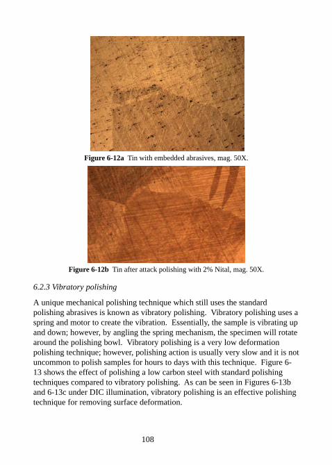
108
Figure 6-12a Tin with embedded abrasives, mag. 50X.
Figure 6-12b Tin after attack polishing with 2% Nital, mag. 50X.
6.2.3 Vibratory polishing
A unique mechanical polishing technique which still uses the standardpolishing abrasives is known as vibratory polishing. Vibratory polishing uses aspring and motor to create the vibration. Essentially, the sample is vibrating upand down; however, by angling the spring mechanism, the specimen will rotatearound the polishing bowl. Vibratory polishing is a very low deformationpolishing technique; however, polishing action is usually very slow and it is notuncommon to polish samples for hours to days with this technique. Figure 6-13 shows the effect of polishing a low carbon steel with standard polishingtechniques compared to vibratory polishing. As can be seen in Figures 6-13band 6-13c under DIC illumination, vibratory polishing is an effective polishingtechnique for removing surface deformation.
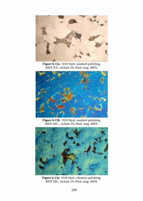
109
Figure 6-13a 1018 Steel, standard polishing,400X B.F., etchant 2% Nital, mag. 400X.
Figure 6-13b 1018 Steel, standard polishing,400X DIC., etchant 2% Nital, mag. 400X.
Figure 6-13a 1018 Steel, vibratory polishing,400X DIC, etchant 2% Nital, mag. 400X.
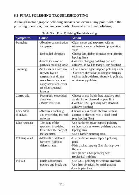
110
6.3 FINAL POLISHING TROUBLESHOOTING
Although metallographic polishing artifacts can occur at any point within thepolishing operation, they are commonly observed after final polishing.
Table XXI. Final Polishing Troubleshooting
smotpmyS esuaC noitcAsehctarcS noitanimatnocevisarbA-
revo-yrrac
sevisarbadeddebmE-
ronoisulcnielbairF-esoolgnikaerbselcitrap
nahtiwnemicepsdnatnuomnaelC-noitaraperpneewtebnirenaelccinosartlu
spetsanimula.g.e(sevisarbaelbairfsselesoohC-
)smlifgnippaldnadapgnihsilopgnignahcredisnoC-
gnihsilopPMCgniyrtsallewsa,evisarbagniraemS wolhtiwslairetamtfoS-
noitazillatsyrcertonodserutarepmetnacdnanedrahkrow
revocdnaraemsylisaelarutcurtsorcimpu
serutaef
htolcgnihsilopdeppanrehgihretfosaesU-seuqinhcetgnihsilopevitanretlaredisnoC-
gnihsilopcitylortcele,gnihsilop-hctesahcusgnihsilopyrotarbivro
sliattemoC deddebme/derutcarF-sevisarba
snoisulcnielttirB-
hcusevisarbadexifelbairfsselaesoohC-smlifgnippaldnomaidroanimulasa
dradnatshtiwgnihsilopPMCenibmoC-gnihsilopevisarba
deddebmEsevisarba
gnirutcarfsevisarbA-tfosotnigniddebmedna
slairetam
sahcusevisarbaelbairfsselaesoohC-dnobdexifahtiwdnomaidroanimula
)smlifgnippal.g.e(gnidnuoregdE ehtfoegdeehT-
dehsilopsinemicepsfoydobehtnehtretsaf
nemicepseht
gnihsilopdeppan-rewolroredrahesU-rosdapgnihsilopnevowsahcussecafrus
smlifgnippalnisergnitnuomredrahaesU-
feilergnihsiloP tnereffidfoslairetaM-tahsilop'ssendrah
setartnereffid
gnihsilopdeppan-rewolroredrahesU-sdap
evorpmioslasmlifgnippaldekcabnialP-ssentalf
htiwgnihsilopPMCetaroprocnI-gnihsiloplacinahcem
tuo-lluP stneutitsnocelttirB-tuokaerbdnaerutcarf
slairetamcimarecrofgnihsilopPMCesU-gnidnirglaitinirofsevisarbarenifesU-
smlifgnippalesU-
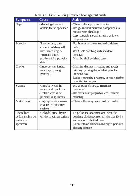
111
Table XXI. Final Polishing Trouble Shooting (continued)
smotpmyS esuaC noitcAspaG tonseodgnitnuoM-
nemicepsehtoterehdagnitnuomotroirpecafrusnaelC-
otsdnuopmocgnitnuomdellif-ssalgesU-egaknirhsniserecuder
rewoltasnisergnitnuomelbatsaceruC-serutarepmet
ytisoroP retfaytisoropeurT-lliwgnihsiloptcerroc
.segdeprahsevahsegdedednuoR
ytisoropeslafecudorpatad
gnihsilopdeppan-rewolroredrahesU-sdap
dradnatshtiwgnihsilopPMCesU-sevisarba
emitgnihsiloplanifeziminiM-
skcarC ,gninoitcesreporpmI-hguorrognitnuom
gnidnirg
hguordnagnittuctaegamadeziminiM-elbissoptsellamsehtgnisuybgnidnirg
ezisevisarbaelbatsacesuro,erusserpgnitnuomecudeR-
seuqinhcetgnitnuomgniniatS ehtneewtebspaG-
nemicepsdnatnuomroskcarcdellifnU-
nemicepsniytisorop
gnitnuomegaknirhsrewolaesU-dnuopmoc
elbatsacdnanoitangerpmimuucavesU-gnitnuom
hsinifdettaM animulaenillatsyrcyloP-nemicepsehtgnitaoc
ecafrus
llabnottocdnaretawypaoshtiwnaelC-
dezillatsyrCnoacilisladiolloc
foecafrusnemiceps
gniyrdacilisladiolloC-ecafrusnemicepsehtno
ehtnaelcdnanemicepsehthsilop-eR-03-51tsalehtrofnemiceps/htolcgnihsilop
retawdellitsidhtiwsdnocesedixorepnegordyh/ainommanahtiwnaelC-
noitulosgninaelc
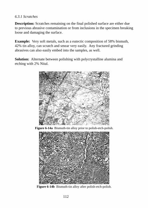
112
6.3.1 Scratches
Description: Scratches remaining on the final polished surface are either dueto previous abrasive contamination or from inclusions in the specimen breakingloose and damaging the surface.
Example: Very soft metals, such as a eutectic composition of 58% bismuth,42% tin alloy, can scratch and smear very easily. Any fractured grindingabrasives can also easily embed into the samples, as well.
Solution: Alternate between polishing with polycrystalline alumina andetching with 2% Nital.
Figure 6-14a Bismuth-tin alloy prior to polish-etch-polish.
Figure 6-14b Bismuth-tin alloy after polish-etch-polish.
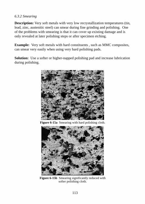
113
6.3.2 Smearing
Description: Very soft metals with very low recrystallization temperatures (tin,lead, zinc, austenitic steel) can smear during fine grinding and polishing. Oneof the problems with smearing is that it can cover up existing damage and isonly revealed at later polishing steps or after specimen etching.
Example: Very soft metals with hard constituents , such as MMC composites,can smear very easily when using very hard polishing pads.
Solution: Use a softer or higher-napped polishing pad and increase lubricationduring polishing.
Figure 6-15a Smearing with hard polishing cloth.
Figure 6-15b Smearing significantly reduced withsofter polishing cloth.
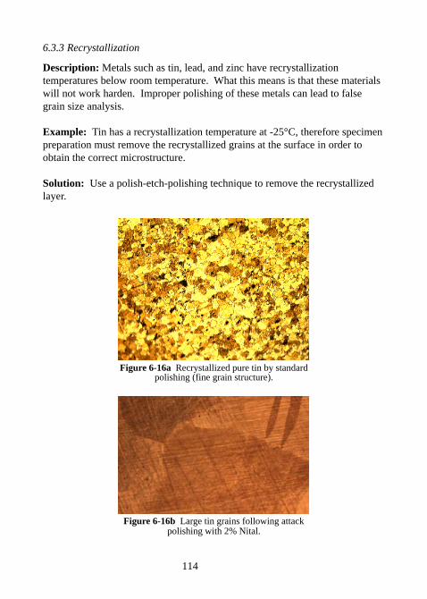
114
6.3.3 Recrystallization
Description: Metals such as tin, lead, and zinc have recrystallizationtemperatures below room temperature. What this means is that these materialswill not work harden. Improper polishing of these metals can lead to falsegrain size analysis.
Example: Tin has a recrystallization temperature at -25°C, therefore specimenpreparation must remove the recrystallized grains at the surface in order toobtain the correct microstructure.
Solution: Use a polish-etch-polishing technique to remove the recrystallizedlayer.
Figure 6-16a Recrystallized pure tin by standardpolishing (fine grain structure).
Figure 6-16b Large tin grains following attackpolishing with 2% Nital.
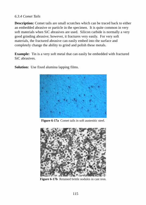
115
6.3.4 Comet Tails
Description: Comet tails are small scratches which can be traced back to eitheran embedded abrasive or particle in the specimen. It is quite common in verysoft materials when SiC abrasives are used. Silicon carbide is normally a verygood grinding abrasive; however, it fractures very easily. For very softmaterials, the fractured abrasive can easily embed into the surface andcompletely change the ability to grind and polish these metals.
Example: Tin is a very soft metal that can easily be embedded with fracturedSiC abrasives.
Solution: Use fixed alumina lapping films.
Figure 6-17a Comet tails in soft austenitic steel.
Figure 6-17b Retained brittle nodules in cast iron.
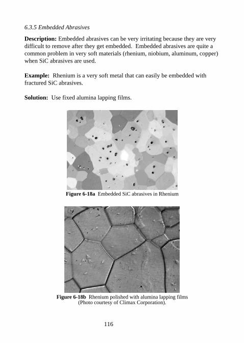
116
6.3.5 Embedded Abrasives
Description: Embedded abrasives can be very irritating because they are verydifficult to remove after they get embedded. Embedded abrasives are quite acommon problem in very soft materials (rhenium, niobium, aluminum, copper)when SiC abrasives are used.
Example: Rhenium is a very soft metal that can easily be embedded withfractured SiC abrasives.
Solution: Use fixed alumina lapping films.
Figure 6-18a Embedded SiC abrasives in Rhenium
Figure 6-18b Rhenium polished with alumina lapping films(Photo courtesy of Climax Corporation).
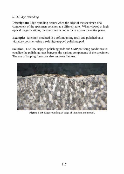
117
6.3.6 Edge Rounding
Description: Edge rounding occurs when the edge of the specimen or acomponent of the specimen polishes at a different rate. When viewed at highoptical magnifications, the specimen is not in focus across the entire plane.
Example: Rhenium mounted in a soft mounting resin and polished on avibratory polisher using a soft high-napped polishing pad.
Solution: Use low-napped polishing pads and CMP polishing conditions toequalize the polishing rates between the various components of the specimen.The use of lapping films can also improve flatness.
Figure 6-19 Edge rounding at edge of titanium and mount.
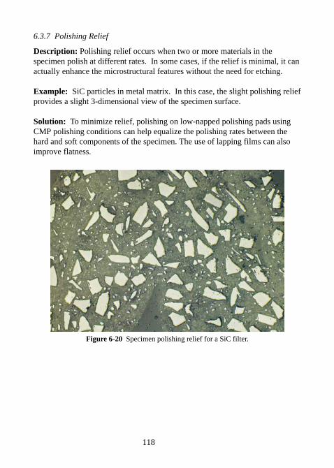
118
6.3.7 Polishing Relief
Description: Polishing relief occurs when two or more materials in thespecimen polish at different rates. In some cases, if the relief is minimal, it canactually enhance the microstructural features without the need for etching.
Example: SiC particles in metal matrix. In this case, the slight polishing reliefprovides a slight 3-dimensional view of the specimen surface.
Solution: To minimize relief, polishing on low-napped polishing pads usingCMP polishing conditions can help equalize the polishing rates between thehard and soft components of the specimen. The use of lapping films can alsoimprove flatness.
Figure 6-20 Specimen polishing relief for a SiC filter.
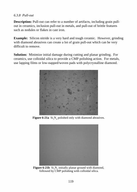
119
6.3.8 Pull-out
Description: Pull-out can refer to a number of artifacts, including grain pull-out in ceramics, inclusion pull-out in metals, and pull-out of brittle featuressuch as nodules or flakes in cast iron.
Example: Silicon nitride is a very hard and tough ceramic. However, grindingwith diamond abrasives can create a lot of grain pull-out which can be verydifficult to remove.
Solution: Minimize initial damage during cutting and planar grinding. Forceramics, use colloidal silica to provide a CMP polishing action. For metals,use lapping films or low-napped/woven pads with polycrystalline diamond.
Figure 6-21a Si3N
4 polished only with diamond abrasives.
Figure 6-21b Si3N
4 initially planar ground with diamond,
followed by CMP polishing with colloidal silica.
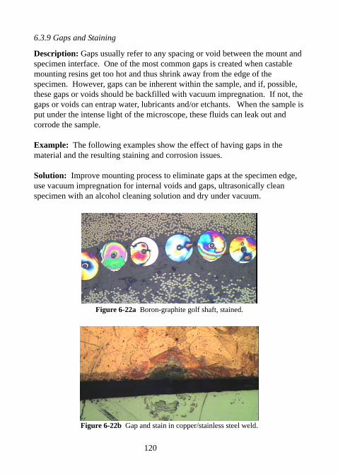
120
6.3.9 Gaps and Staining
Description: Gaps usually refer to any spacing or void between the mount andspecimen interface. One of the most common gaps is created when castablemounting resins get too hot and thus shrink away from the edge of thespecimen. However, gaps can be inherent within the sample, and if, possible,these gaps or voids should be backfilled with vacuum impregnation. If not, thegaps or voids can entrap water, lubricants and/or etchants. When the sample isput under the intense light of the microscope, these fluids can leak out andcorrode the sample.
Example: The following examples show the effect of having gaps in thematerial and the resulting staining and corrosion issues.
Solution: Improve mounting process to eliminate gaps at the specimen edge,use vacuum impregnation for internal voids and gaps, ultrasonically cleanspecimen with an alcohol cleaning solution and dry under vacuum.
Figure 6-22a Boron-graphite golf shaft, stained.
Figure 6-22b Gap and stain in copper/stainless steel weld.
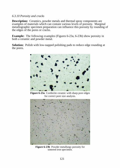
121
6.3.10 Porosity and cracks
Description: Ceramics, powder metals and thermal spray components areexamples of materials which can contain various levels of porosity. Marginalmetallographic specimen preparation can influence this porosity by rounding ofthe edges of the pores or cracks.
Example: The following examples (Figures 6-23a, 6-23b) show porosity inboth a ceramic and powder metal.
Solution: Polish with low-napped polishing pads to reduce edge rounding atthe pores.
Figure 6-23a Cordierite ceramic with sharp pore edgesfor correct pore size analysis.
Figure 6-23b Powder metallurgy porosity forsintered iron specimen.
122
CHAPTER 7Electrolytic Polishing
7.0 ELECTROLYTIC POLISHING
A less commonly used polishing technique is electrolytic polishing.Electrolytic polishing/etching, commonly known as anodic dissolution, isperhaps the best way to polish very soft materials which are prone tosmearing and deformation. Materials that work well for electropolishing oretching include soft austenitic stainless steels, aluminum and aluminumalloys, copper and copper alloys, among others. The primary requirement forelectropolishing is that the specimen be conductive.
Electrolytic polishing/etching essentially dissolves the higher surface energysites associated with rough surfaces by smoothing the rough ridges or peaks.This is accomplished by making the specimen surface the anode in anelectrolytic cell.
The voltage-current density plot shown in Figure 7-1 represents themechanism by which electrolytic etching and polishing occurs. In Zone I, theprimary mechanism is the direct dissolution of the metal. In this region,etching occurs. Zone II represents the voltage-current density conditionswhere the metal begins to form a passivation layer. In Zone III, thepassivation layer is stable and dissolution of the metal is primarily bydiffusion through the passivated layer. In this region, the higher surface areapeaks dissolve preferentially to the lower surface area valleys, thus providinga polishing, or smoothing, effect to the surface. By increasing the voltageinto Zone IV, the passivation layer breaks down as the oxygen evolutionoccurs at the surface. In this zone, the metal will begin to pit.
7.1 SPECIMEN PREPARATION
It is recommended that the specimen be rough polished down to a 600 or1200 grit SiC surface finish. The specimen/mount must be conductive and incontact with the electrolyte, as well as the anode connection.
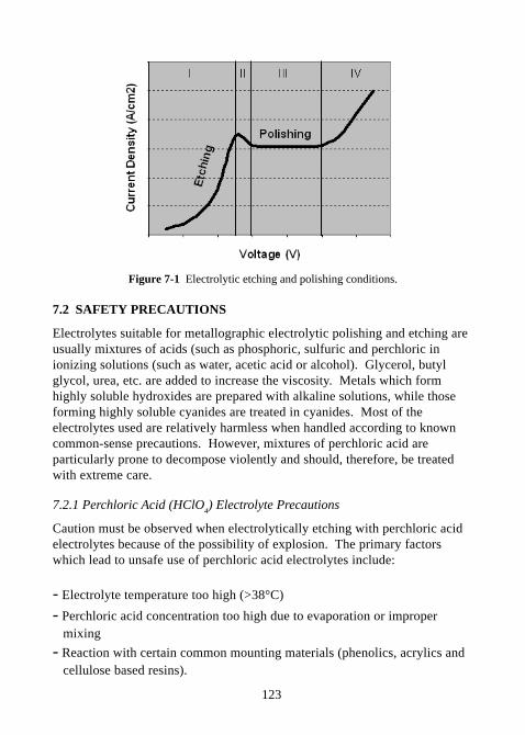
123
Figure 7-1 Electrolytic etching and polishing conditions.
7.2 SAFETY PRECAUTIONS
Electrolytes suitable for metallographic electrolytic polishing and etching areusually mixtures of acids (such as phosphoric, sulfuric and perchloric inionizing solutions (such as water, acetic acid or alcohol). Glycerol, butylglycol, urea, etc. are added to increase the viscosity. Metals which formhighly soluble hydroxides are prepared with alkaline solutions, while thoseforming highly soluble cyanides are treated in cyanides. Most of theelectrolytes used are relatively harmless when handled according to knowncommon-sense precautions. However, mixtures of perchloric acid areparticularly prone to decompose violently and should, therefore, be treatedwith extreme care.
7.2.1 Perchloric Acid (HClO4) Electrolyte Precautions
Caution must be observed when electrolytically etching with perchloric acidelectrolytes because of the possibility of explosion. The primary factorswhich lead to unsafe use of perchloric acid electrolytes include:
- Electrolyte temperature too high (>38°C)
- Perchloric acid concentration too high due to evaporation or improper mixing
- Reaction with certain common mounting materials (phenolics, acrylics and cellulose based resins).
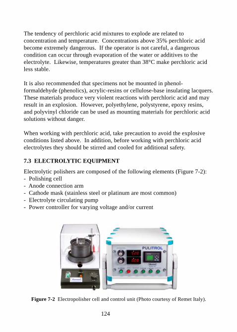
124
The tendency of perchloric acid mixtures to explode are related toconcentration and temperature. Concentrations above 35% perchloric acidbecome extremely dangerous. If the operator is not careful, a dangerouscondition can occur through evaporation of the water or additives to theelectrolyte. Likewise, temperatures greater than 38°C make perchloric acidless stable.
It is also recommended that specimens not be mounted in phenol-formaldehyde (phenolics), acrylic-resins or cellulose-base insulating lacquers.These materials produce very violent reactions with perchloric acid and mayresult in an explosion. However, polyethylene, polystyrene, epoxy resins,and polyvinyl chloride can be used as mounting materials for perchloric acidsolutions without danger.
When working with perchloric acid, take precaution to avoid the explosiveconditions listed above. In addition, before working with perchloric acidelectrolytes they should be stirred and cooled for additional safety.
7.3 ELECTROLYTIC EQUIPMENT
Electrolytic polishers are composed of the following elements (Figure 7-2):- Polishing cell- Anode connection arm- Cathode mask (stainless steel or platinum are most common)- Electrolyte circulating pump- Power controller for varying voltage and/or current
Figure 7-2 Electropolisher cell and control unit (Photo courtesy of Remet Italy).
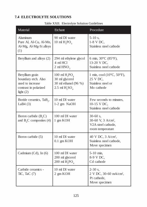
125
7.4 ELECTROLYTE SOLUTIONS
Table XXII. Electrolyte Solution Guidelines
lairetaM tnahctE erudecorP
munimulA,nM-lA,uC-lA,lAeruPsyollaiS-gM-lA,gM-lA
)1(
retawIDlm09Hlm01
3OP
4
,s01-5,CDV8-1
edohtacleetssselniatS
)2(syolladnamuillyreB locylgenelyhtelm492lCHlm4ONHlm2
3
,)F°58(C°03,nim6,CDV02-31
edohtacleetssselniatS
niargmuillyreBoslA.hcteyradnuob
esaercniotdesudeziralopnitsartnoc
)2(thgil
Hlm0013
OP4
lorecylglm03)%69(lonahtelm03
Hlm5.22
OS4
,)F°05,C°01(looc,nim1,CDV52
roleetssselniatSedohtacoM
BaT,scimarecediroB2,
)3(4BaLretawIDlm01
HOaNmg2-1,setunimotsdnocesweF
,CDV51-01edohtacleetssselniatS
B(edibracnoroB4
)CBdna
4)4(setisopmocC
retawIDlm001HOKmg1
,s06-03mc/A3,V06-03 2,
,edohtacleetsA2Verutarepmetmoor
)5(edibracnoroB retawIDlm01HOKmg1.0
mc/A3,CDV04 2,,edohtacleetssselniatS
nemicepsevoM
)6(nI,)dC(muimdaC retawIDlm001lorecylglm002
Hlm0023
OP4
,nim01-5,CDV9-8edohtacdC
-scimarecedibraC)7(CaT,CiT
retawIDlm01HOKmg2
,s03-2mc/Am06-03,CDV2 2,
,edohtactPnemicepsevoM
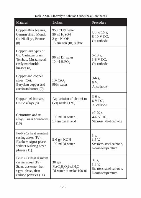
126
Table XXII. Electrolyte Solution Guidelines (Continued)
lairetaM tnahctE erudecorP
,sessarbateB-reppoC,lenoM,revlisnamreG
eznorB,syollaiN-uC.)8(
retawIDlm059Hlm05
24OS
HOaNmg2etaflus)III(norimg51
,s51otpU,CDV01-8
edohtacuC
fosepytllA-reppoC.ssarbegdirtraC.uC
,latemztnuM.cabmoTelbanihcamylisae
)8(sessarb
retawIDlm09Hlm01
3OP
4
,s01-5,CDV8-1edohtacuC
reppocdnareppoC,)uC(syolla
dnareppocmuillyreB)9(eznorbmunimula
OrC%13
retaw%99
,s6-3,V6
edohtaclA
,seznorblA-reppoC)8(syollaeB-uC
muimorhcfonoitulos.qA)%1(edixo)IV(
,s6-3,CDV6
edohtaclA
stidnamuinamreGseiradnuobniarG.syolla
)01(
retawIDlm001dicacilaxomg01
,s02-01,CDV6-4
edohtacleetssselniatS
tnatsisertaehrC-iN-eF.)eF(syollagnitsac
esahpamgissnekcalBrehtogniniltuotuohtiw
.)11(sesahp
HOKmg6-5retawIDlm001
,s1,V5.1
,edohtacleetssselniatSerutarepmetmooR
tnatsisertaehrC-iN-eF.)eF(syollagnitsac
neht,etinetsuasniatSneht,esahpamgis
)11(selcitrapedibrac
mg83C(bP
2H
2O
2)2 H3x
2O
lm001ekamotretawID
,s03,V5.1
,edohtacleetssselniatSerutarepmetmooR
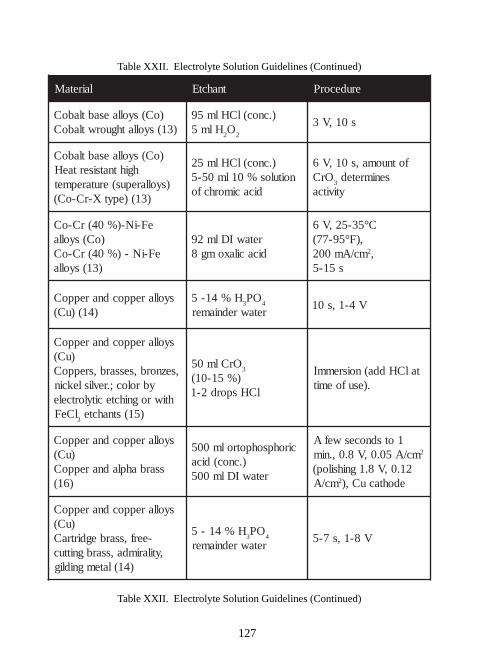
127
Table XXII. Electrolyte Solution Guidelines (Continued)
lairetaM tnahctE erudecorP
)oC(syollaesabtlaboC)31(syollathguorwtlaboC
).cnoc(lCHlm59Hlm5
2O
2
s01,V3
)oC(syollaesabtlaboChgihtnatsisertaeH
)syollarepus(erutarepmet)31()epytX-rC-oC(
).cnoc(lCHlm52noitulos%01lm05-5
dicacimorhcfo
fotnuoma,s01,V6OrC
3senimreted
ytivitca
eF-iN-)%04(rC-oC)oC(syolla
eF-iN-)%04(rC-oC)31(syolla
retawIDlm29dicacilaxomg8
C°53-52,V6,)F°59-77(mc/Am002 2,
s51-5
syollareppocdnareppoC)41()uC(
H%41-53
OP4
retawredniamerV4-1,s01
syollareppocdnareppoC)uC(
,seznorb,sessarb,sreppoCybroloc;.revlislekcin
htiwrognihctecitylortcelelCeF3
)51(stnahcte
OrClm053
)%51-01(lCHspord2-1
talCHdda(noisremmI.)esufoemit
syollareppocdnareppoC)uC(
ssarbahpladnareppoC)61(
cirohpsohpotrolm005).cnoc(dica
retawIDlm005
1otsdnoceswefAmc/A50.0,V8.0,.nim 2
21.0,V8.1gnihsilop(mc/A 2 edohtacuC,)
syollareppocdnareppoC)uC(
-eerf,ssarbegdirtraC,ytilarimda,ssarbgnittuc
)41(latemgnidlig
H%41-53
OP4
retawredniamerV8-1,s7-5
Table XXII. Electrolyte Solution Guidelines (Continued)
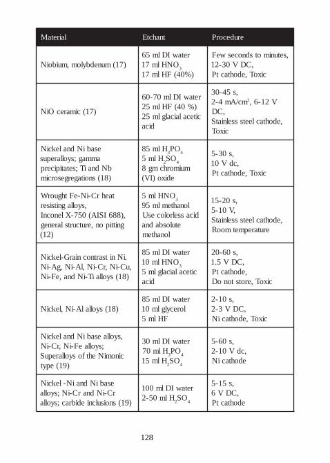
128
lairetaM tnahctE erudecorP
)71(munedbylom,muiboiNretawIDlm56
ONHlm713
)%04(FHlm71
,setunimotsdnocesweF,CDV03-21
cixoT,edohtactP
)71(cimarecOiN
retawIDlm07-06)%04(FHlm52citecalaicalglm52
dica
,s54-03mc/Am4-2 2 V21-6,
,CD,edohtacleetssselniatS
cixoT
esabiNdnalekciNammag;syollarepus
bNdnaiT;setatipicerp)81(snoitagergesorcim
Hlm583
OP4
Hlm52
OS4
muimorhcmg8edixo)IV(
,s03-5,cdV01
cixoT,edohtactP
taehrC-iN-eFthguorW,syollagnitsiser
,)886ISIA(057-XlenocnIgnittipon,erutcurtslareneg
)21(
ONHlm53
lonahtemlm59dicasselrolocesU
etulosbadnalonahtem
,s02-51,V01-5
,edohtacleetssselniatSerutarepmetmooR
.iNnitsartnocniarG-lekciN,uC-iN,rC-iN,lA-iN,gA-iN
)81(syollaiT-iNdna,eF-iN
retawIDlm58ONHlm01
3
citecalaicalglm5dica
,s06-02,CDV5.1,edohtactP
cixoT,erotstonoD
)81(syollalA-iN,lekciNretawIDlm58
lorecylglm01FHlm5
,s01-2,CDV3-2
cixoT,edohtaciN
,syollaesabiNdnalekciN;syollaeF-iN,rC-iN
cinomiNehtfosyollarepuS)91(epyt
retawIDlm03Hlm07
3OP
4
Hlm512
OS4
,s06-5,cdV01-2edohtaciN
esabiNdnaiN-lekciNrC-iNdnarC-iN;syolla
)91(snoisulcniedibrac;syolla
retawIDlm001Hlm05-2
2OS
4
,s51-5,CDV6
edohtactP
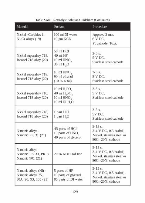
129
Table XXII. Electrolyte Solution Guidelines (Continued)
lairetaM tnahctE erudecorP
nisedibraC-lekciN)91(syollarC-iN
retawIDlm001NCKmg01
,nim3.xorppA,CDV6
cixoT,edohtactP
,817yollarepuslekciN)02(yolla817lenocnI
lCHlm05FHlm04
ONHlm013
Hlm032O
,s5-3,CDV5
edohtacleetssselniatS
,817yollarepuslekciN)02(yolla817lenocnI
ONHlm013
lonahtelm09)latiN%01(
,s5-3,CDV5
edohtacleetssselniatS
,817yollarepuslekciN)02(yolla817lenocnI
Hlm013
OP4
Hlm042
OS4
ONHlm013
HIDlm012O
,s5-3,CDV5
edohtacleetssselniatS
,817yollarepuslekciN)02(yolla817lenocnI
lCHtrap1Htrap1
2O
,s5-3,CDV5
edohtacleetssselniatS
-syollacinomiN)12(13KPcinomiN
lCHfostrap54ONHfostrap51
3
lorecylgfostrap04
,s51-5md/A5.0,CDV4-2 2,
roleetssselniats,lekciNedohtaciN02-rC08
-syollacinomiN05KP,33KPcinomiN
)12(109cinomiNnoitulosHOK%02
,s51-5md/A5.0,CDV4-2 2,
roleetssselniats,lekciNedohtaciN02-rC08
-)iN(syollacinomiN,57syollacinomiN
)12(501,39,09,A08
FHfostrap5lorecylgfostrap01retawIDfostrap58
,s51-5md/A5.0,CDV4-2 2,
roleetssselniats,lekciNedohtaciN02-rC08
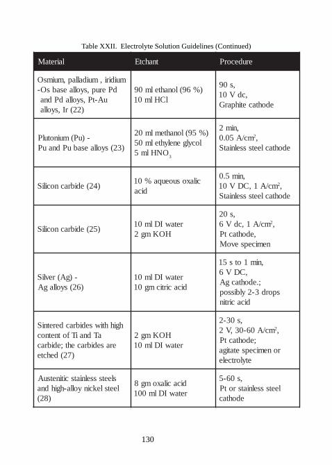
130
Table XXII. Electrolyte Solution Guidelines (Continued)
lairetaM tnahctE erudecorP
muidiri,muidallap,muimsOdPerup,syollaesabsO-
uA-tP,syolladPdna)22(rI,syolla
)%69(lonahtelm09lCHlm01
,s09,cdV01
edohtacetihparG
-)uP(muinotulP)32(syollaesabuPdnauP
)%59(lonahtemlm02locylgenelyhtelm05
ONHlm53
,nim2mc/A50.0 2,
edohtacleetssselniatS
)42(edibracnociliScilaxosuoeuqa%01
dica
,nim5.0mc/A1,CDV01 2,
edohtacleetssselniatS
)52(edibracnociliSretawIDlm01
HOKmg2
,s02mc/A1,cdV6 2,
,edohtactPnemicepsevoM
-)gA(revliS)62(syollagA
retawIDlm01dicacirticmg01
,nim1ots51,CDV6
;.edohtacgAspord3-2ylbissop
dicacirtin
hgihhtiwsedibracderetniSaTdnaiTfotnetnoc
erasedibraceht;edibrac)72(dehcte
HOKmg2retawIDlm01
,s03-2mc/A06-03,V2 2,
;edohtactPronemicepsetatiga
etylortcele
sleetssselniatscitinetsuAleetslekcinyolla-hgihdna
)82(
dicacilaxomg8retawIDlm001
,s06-5leetssselniatsrotP
edohtac
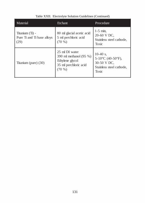
131
Table XXII. Electrolyte Solution Guidelines (Continued)
lairetaM tnahctE erudecorP
-)iT(muinatiTsyollaesabiTdnaiTeruP
)92(
dicacitecalaicalglm08dicacirolhcreplm5
)%07(
,nim5-1,CDV06-02
,edohtacleetssselniatScixoT
)03()erup(muinatiT
retawIDlm52)%59(lonahtemlm093
locylgenelyhtEdicacirolhcreplm53
)%07(
,s04-01,)F°05-04(C°01-5
,CDV05-03,edohtacleetssselniatS
cixoT
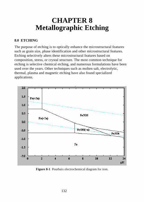
132
CHAPTER 8Metallographic Etching
8.0 ETCHING
The purpose of etching is to optically enhance the microstructural featuressuch as grain size, phase identification and other microstructural features.Etching selectively alters these microstructural features based oncomposition, stress, or crystal structure. The most common technique foretching is selective chemical etching, and numerous formulations have beenused over the years. Other techniques such as molten salt, electrolytic,thermal, plasma and magnetic etching have also found specializedapplications.
Figure 8-1 Pourbaix electrochemical diagram for iron.
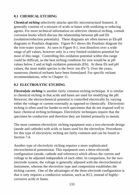
133
8.1 CHEMICAL ETCHING
Chemical etching selectively attacks specific microstructural features. Itgenerally consists of a mixture of acids or bases with oxidizing or reducingagents. For more technical information on selective chemical etching, consultcorrosion books which discuss the relationship between pH and Eh(oxidation/reduction potentials). These diagrams are often known as Eh-pHdiagrams or Pourbaix diagrams. Figure 8-1 shows the Pourbaix diagram forthe iron-water system. As seen in Figure 8-1, iron dissolves over a widerange of pH values, however only in a very limited oxidation potential formost of this range. Controlling this oxidation potential within this rangecould be difficult, so the best etching condition for iron would be at pHvalues below 2 and at high oxidation potentials (Eh). At these Eh and pHvalues, the most stable species is the ferric ion (Fe+3). Over the years,numerous chemical etchants have been formulated. For specific etchantrecommendations, refer to Chapter 11.
8.2 ELECTROLYTIC ETCHING
Electrolytic etching is another fairly common etching technique. It is similarto chemical etching in that acids and bases are used for modifying the pH.However, the electrochemical potential is controlled electrically by varyingeither the voltage or current externally as opposed to chemically. Electrolyticetching is often used for harder-to-etch specimens that do not respond well tobasic chemical etching techniques. Electrolytic techniques require that thespecimen be conductive and therefore they are limited primarily to metals.
The most common electrolytic etching equipment uses a two-electrode design(anode and cathode) with acids or bases used for the electrolyte. Proceduresfor this type of electrolytic etching are fairly common and can be found inSection 7.4.
Another type of electrolytic etching requires a more sophisticatedelectrochemical potentiostat. This equipment uses a three-electrodeconfiguration (anode, cathode and reference) which allows the current andvoltage to be adjusted independent of each other. In comparison, for the two-electrode system, the voltage is generally adjusted with the electrochemicalinstrument, whereas the electrolyte type and composition establishes theetching current. One of the advantages of the three-electrode configuration isthat it only requires a conductive solution, such as KCl, instead of highly-corrosive acids or bases.
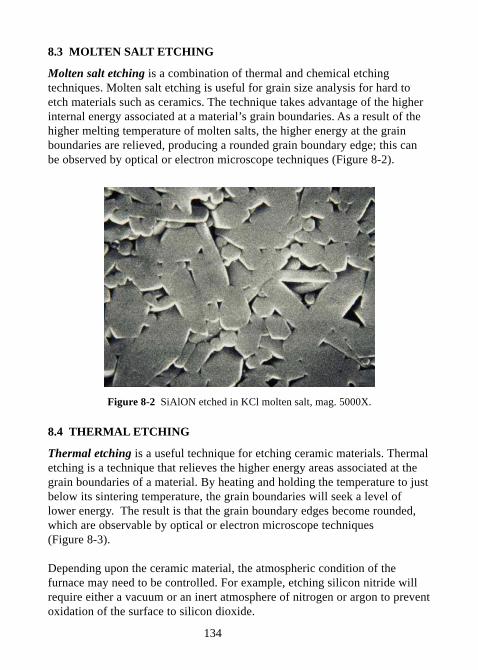
134
8.3 MOLTEN SALT ETCHING
Molten salt etching is a combination of thermal and chemical etchingtechniques. Molten salt etching is useful for grain size analysis for hard toetch materials such as ceramics. The technique takes advantage of the higherinternal energy associated at a material’s grain boundaries. As a result of thehigher melting temperature of molten salts, the higher energy at the grainboundaries are relieved, producing a rounded grain boundary edge; this canbe observed by optical or electron microscope techniques (Figure 8-2).
Figure 8-2 SiAlON etched in KCl molten salt, mag. 5000X.
8.4 THERMAL ETCHING
Thermal etching is a useful technique for etching ceramic materials. Thermaletching is a technique that relieves the higher energy areas associated at thegrain boundaries of a material. By heating and holding the temperature to justbelow its sintering temperature, the grain boundaries will seek a level oflower energy. The result is that the grain boundary edges become rounded,which are observable by optical or electron microscope techniques(Figure 8-3).
Depending upon the ceramic material, the atmospheric condition of thefurnace may need to be controlled. For example, etching silicon nitride willrequire either a vacuum or an inert atmosphere of nitrogen or argon to preventoxidation of the surface to silicon dioxide.
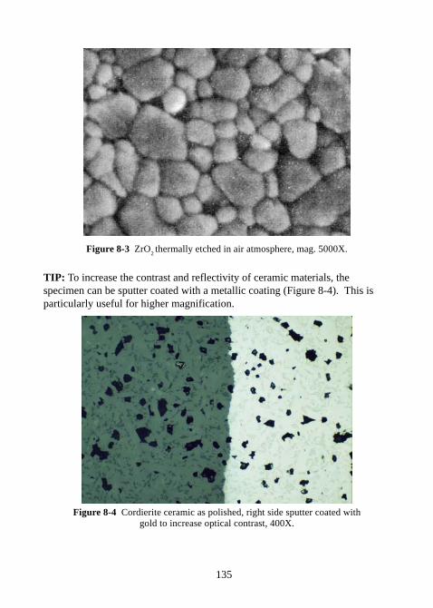
135
Figure 8-3 ZrO2 thermally etched in air atmosphere, mag. 5000X.
TIP: To increase the contrast and reflectivity of ceramic materials, thespecimen can be sputter coated with a metallic coating (Figure 8-4). This isparticularly useful for higher magnification.
Figure 8-4 Cordierite ceramic as polished, right side sputter coated withgold to increase optical contrast, 400X.
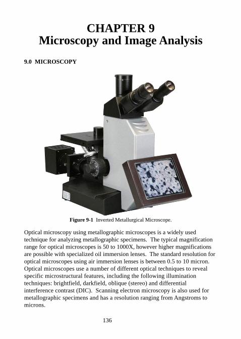
136
CHAPTER 9Microscopy and Image Analysis
9.0 MICROSCOPY
Figure 9-1 Inverted Metallurgical Microscope.
Optical microscopy using metallographic microscopes is a widely usedtechnique for analyzing metallographic specimens. The typical magnificationrange for optical microscopes is 50 to 1000X, however higher magnificationsare possible with specialized oil immersion lenses. The standard resolution foroptical microscopes using air immersion lenses is between 0.5 to 10 micron.Optical microscopes use a number of different optical techniques to revealspecific microstructural features, including the following illuminationtechniques: brightfield, darkfield, oblique (stereo) and differentialinterference contrast (DIC). Scanning electron microscopy is also used formetallographic specimens and has a resolution ranging from Angstroms tomicrons.
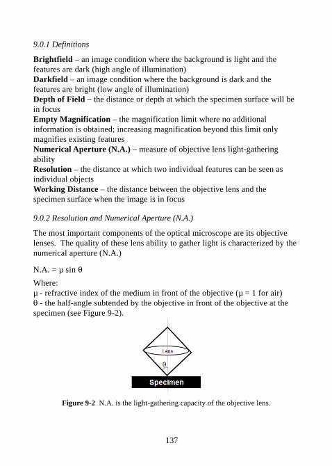
137
9.0.1 Definitions
Brightfield – an image condition where the background is light and thefeatures are dark (high angle of illumination)Darkfield – an image condition where the background is dark and thefeatures are bright (low angle of illumination)Depth of Field – the distance or depth at which the specimen surface will bein focusEmpty Magnification – the magnification limit where no additionalinformation is obtained; increasing magnification beyond this limit onlymagnifies existing featuresNumerical Aperture (N.A.) – measure of objective lens light-gatheringabilityResolution – the distance at which two individual features can be seen asindividual objectsWorking Distance – the distance between the objective lens and thespecimen surface when the image is in focus
9.0.2 Resolution and Numerical Aperture (N.A.)
The most important components of the optical microscope are its objectivelenses. The quality of these lens ability to gather light is characterized by thenumerical aperture (N.A.)
N.A. = µ sin θWhere:µ - refractive index of the medium in front of the objective (µ = 1 for air)θ - the half-angle subtended by the objective in front of the objective at thespecimen (see Figure 9-2).
Figure 9-2 N.A. is the light-gathering capacity of the objective lens.
138
Resolving Power = (2 * N.A.)/λ
λ = wavelength of light usedλ = 0.54 micron – green lightλ = 0.1 Angstrom – electron beam
Limit of Resolution = λ/(2 * N.A.)
Total magnification = objective mag. x eyepiece mag. x tube factor mag.
9.0.3 Optical Filters
Optical filters are used to enhance the definition of the specimen image,especially for photographic film. The main types of optical filters include:Neutral Density Filters - reduce the illumination intensity without affectingthe color temperatureGreen Monochromatic Filters - produce a single wavelength of light toensure a sharp focus on black and white filmBlue Color Correction Filters - allow the operator to use daylight film withtungsten illumination and vice versa.Color Compensating Filters - used to compensate for minor colortemperature differences between the film and the illumination source
9.1 BRIGHTFIELD
Brightfield (B.F.) illumination is the most common illumination technique formetallographic analysis. The light path for B.F. illumination is from thesource, through the objective, reflected off the surface, returning through theobjective, and back to the eyepiece or camera. This type of illuminationproduces a bright background for flat surfaces, with the non-flat features(pores, edges, etched grain boundaries) being darker as light is reflected backat a different angle.
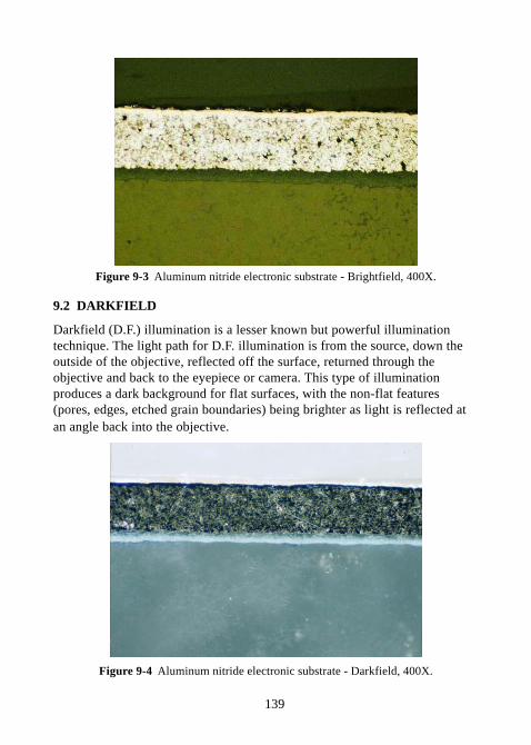
139
Figure 9-3 Aluminum nitride electronic substrate - Brightfield, 400X.
9.2 DARKFIELD
Darkfield (D.F.) illumination is a lesser known but powerful illuminationtechnique. The light path for D.F. illumination is from the source, down theoutside of the objective, reflected off the surface, returned through theobjective and back to the eyepiece or camera. This type of illuminationproduces a dark background for flat surfaces, with the non-flat features(pores, edges, etched grain boundaries) being brighter as light is reflected atan angle back into the objective.
Figure 9-4 Aluminum nitride electronic substrate - Darkfield, 400X.
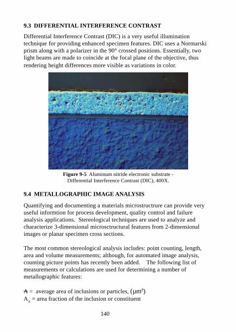
140
9.3 DIFFERENTIAL INTERFERENCE CONTRAST
Differential Interference Contrast (DIC) is a very useful illuminationtechnique for providing enhanced specimen features. DIC uses a Normarskiprism along with a polarizer in the 90° crossed positions. Essentially, twolight beams are made to coincide at the focal plane of the objective, thusrendering height differences more visible as variations in color.
Figure 9-5 Aluminum nitride electronic substrate -Differential Interference Contrast (DIC), 400X.
9.4 METALLOGRAPHIC IMAGE ANALYSIS
Quantifying and documenting a materials microstructrure can provide veryuseful informtion for process development, quality control and failureanalysis applications. Stereological techniques are used to analyze andcharacterize 3-dimensional microsctructural features from 2-dimensionalimages or planar specimen cross sections.
The most common stereological analysis includes: point counting, length,area and volume measurements; although, for automated image analysis,counting picture points has recently been added. The following list ofmeasurements or calculations are used for determining a number ofmetallographic features:
A = average area of inclusions or particles, (µm2)A
A = area fraction of the inclusion or constituent
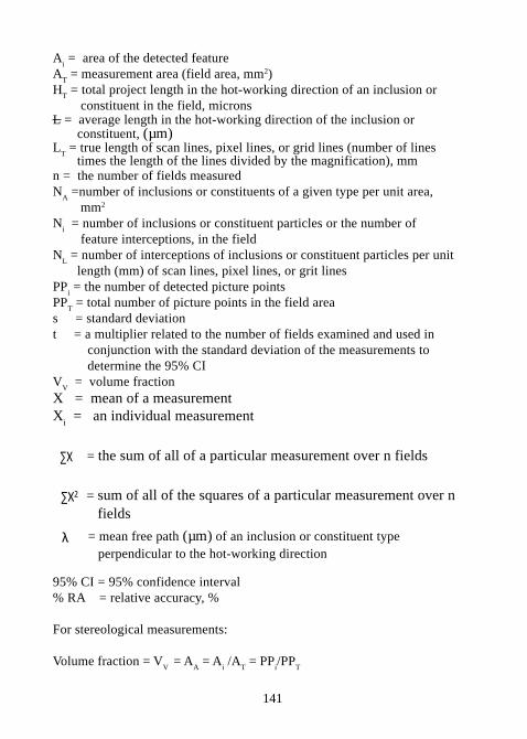
141
Ai = area of the detected feature
AT = measurement area (field area, mm2)
HT = total project length in the hot-working direction of an inclusion or
constituent in the field, micronsL = average length in the hot-working direction of the inclusion or constituent, (µm)L
T = true length of scan lines, pixel lines, or grid lines (number of lines
times the length of the lines divided by the magnification), mmn = the number of fields measuredN
A =number of inclusions or constituents of a given type per unit area,
mm2
Ni = number of inclusions or constituent particles or the number of
feature interceptions, in the fieldN
L = number of interceptions of inclusions or constituent particles per unit
length (mm) of scan lines, pixel lines, or grit linesPP
i = the number of detected picture points
PPT = total number of picture points in the field area
s = standard deviationt = a multiplier related to the number of fields examined and used in conjunction with the standard deviation of the measurements to determine the 95% CIV
V = volume fraction
X = mean of a measurementX
i = an individual measurement
∑X = the sum of all of a particular measurement over n fields
∑X2 = sum of all of the squares of a particular measurement over n fields
λ = mean free path (µm) of an inclusion or constituent type perpendicular to the hot-working direction
95% CI = 95% confidence interval% RA = relative accuracy, %
For stereological measurements:
Volume fraction = VV
= AA = A
i /A
T = PP
i/PP
T
142
Number per unit area (inclusions) = NA =N
i / A
T
Average length of each inclusion =
Average area of each inclusion or particle = A = AA/ N
A
Mean free path or the mean edge-to-edge distance between inclusions (oxideand sulfide) or particle types, perpendicular to the hot-working axis:
λ = (1-AA)/ N
L
Several commonly used metallographic quantification procedures include thefollowing:- Grain size (ASTM E112, E930, E1181 and E1382)- Phase analysis (ASTM E562, E1245)- Nodularity (ASTM A247)- Porosity (ASTM 562)- Inclusion (ASTM E45, E1245)- Decarburization (ASTM E1077)- Coating thickness (ASTM B487)- Weld analysis
9.4.1 Grain size (ASTM E112, E930, E1181)
A grain is defined as the individual crystal in a polycrystalline material.Although grain size is a 3-dimensional feature, it is measured from a 2-dimension cross section of the material. ASTM (American Society forTesting Materials) provides a number of internationally recognized standardsfor measuring and classifying a materials grain size.
- ASTM E112 - Standard Test Methods for Determining Average Grain Size (31)- ASTM 930 - Standard Test Methods for Estimating the Largest Grain Obsvered in a Metallographic Section (ALA Grain Size) (32)-ASTM E1181 - Standard Test Methods for Characterizing Duplex Grain Sizes (33)-ASTM E1382 - Standard Test Methods for Determining Average Grain Size Using Semiautomatic and Automatic Image Analysis (34)
ASTM E112 describes several procedures for measuring grain size, includingthe Comparision procedure, Planimetric (Jeffries) procedure, and generalIntercept procedures.
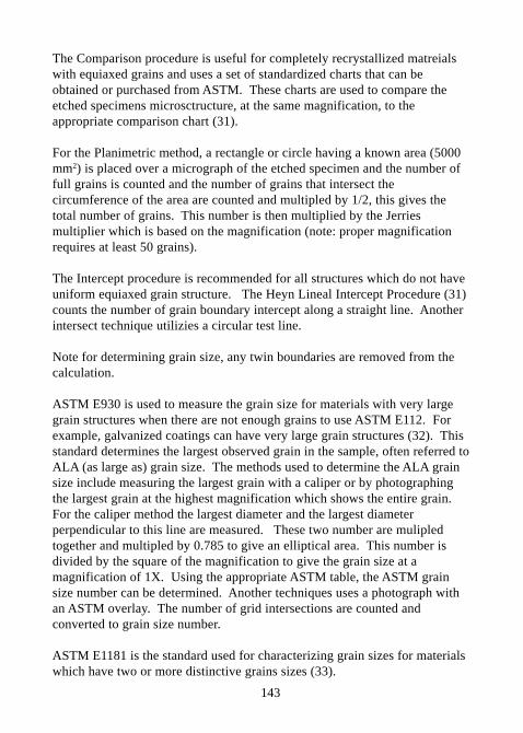
143
The Comparison procedure is useful for completely recrystallized matreialswith equiaxed grains and uses a set of standardized charts that can beobtained or purchased from ASTM. These charts are used to compare theetched specimens microsctructure, at the same magnification, to theappropriate comparison chart (31).
For the Planimetric method, a rectangle or circle having a known area (5000mm2) is placed over a micrograph of the etched specimen and the number offull grains is counted and the number of grains that intersect thecircumference of the area are counted and multipled by 1/2, this gives thetotal number of grains. This number is then multiplied by the Jerriesmultiplier which is based on the magnification (note: proper magnificationrequires at least 50 grains).
The Intercept procedure is recommended for all structures which do not haveuniform equiaxed grain structure. The Heyn Lineal Intercept Procedure (31)counts the number of grain boundary intercept along a straight line. Anotherintersect technique utilizies a circular test line.
Note for determining grain size, any twin boundaries are removed from thecalculation.
ASTM E930 is used to measure the grain size for materials with very largegrain structures when there are not enough grains to use ASTM E112. Forexample, galvanized coatings can have very large grain structures (32). Thisstandard determines the largest observed grain in the sample, often referred toALA (as large as) grain size. The methods used to determine the ALA grainsize include measuring the largest grain with a caliper or by photographingthe largest grain at the highest magnification which shows the entire grain.For the caliper method the largest diameter and the largest diameterperpendicular to this line are measured. These two number are mulipledtogether and multipled by 0.785 to give an elliptical area. This number isdivided by the square of the magnification to give the grain size at amagnification of 1X. Using the appropriate ASTM table, the ASTM grainsize number can be determined. Another techniques uses a photograph withan ASTM overlay. The number of grid intersections are counted andconverted to grain size number.
ASTM E1181 is the standard used for characterizing grain sizes for materialswhich have two or more distinctive grains sizes (33).
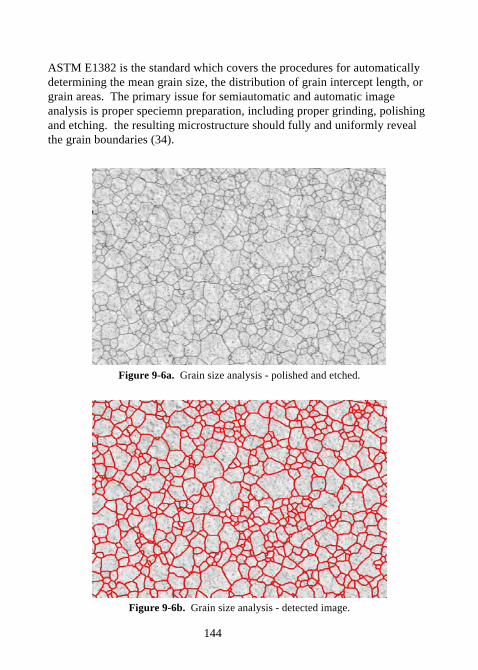
144
ASTM E1382 is the standard which covers the procedures for automaticallydetermining the mean grain size, the distribution of grain intercept length, orgrain areas. The primary issue for semiautomatic and automatic imageanalysis is proper speciemn preparation, including proper grinding, polishingand etching. the resulting microstructure should fully and uniformly revealthe grain boundaries (34).
Figure 9-6a. Grain size analysis - polished and etched.
Figure 9-6b. Grain size analysis - detected image.
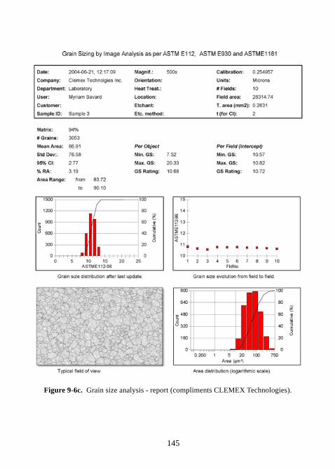
145
Figure 9-6c. Grain size analysis - report (compliments CLEMEX Technologies).
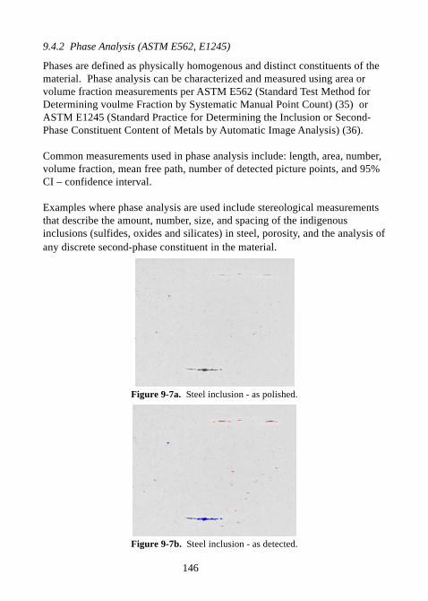
146
9.4.2 Phase Analysis (ASTM E562, E1245)
Phases are defined as physically homogenous and distinct constituents of thematerial. Phase analysis can be characterized and measured using area orvolume fraction measurements per ASTM E562 (Standard Test Method forDetermining voulme Fraction by Systematic Manual Point Count) (35) orASTM E1245 (Standard Practice for Determining the Inclusion or Second-Phase Constituent Content of Metals by Automatic Image Analysis) (36).
Common measurements used in phase analysis include: length, area, number,volume fraction, mean free path, number of detected picture points, and 95%CI – confidence interval.
Examples where phase analysis are used include stereological measurementsthat describe the amount, number, size, and spacing of the indigenousinclusions (sulfides, oxides and silicates) in steel, porosity, and the analysis ofany discrete second-phase constituent in the material.
Figure 9-7a. Steel inclusion - as polished.
Figure 9-7b. Steel inclusion - as detected.
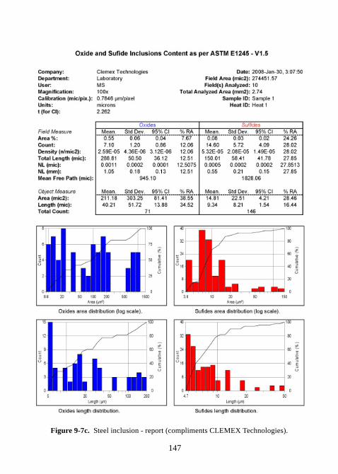
147
Figure 9-7c. Steel inclusion - report (compliments CLEMEX Technologies).
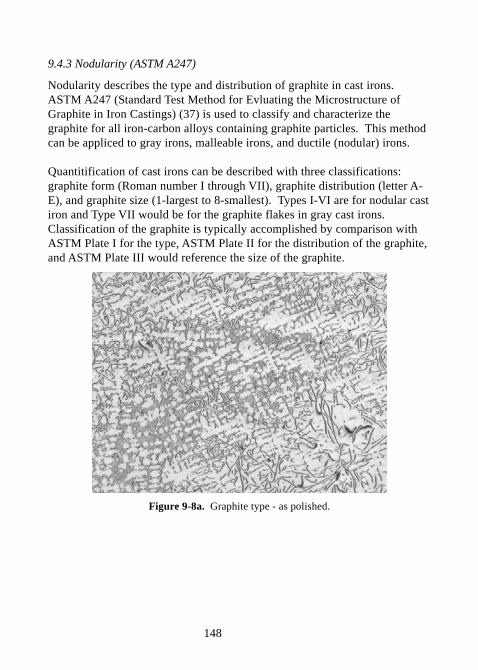
148
9.4.3 Nodularity (ASTM A247)
Nodularity describes the type and distribution of graphite in cast irons.ASTM A247 (Standard Test Method for Evluating the Microstructure ofGraphite in Iron Castings) (37) is used to classify and characterize thegraphite for all iron-carbon alloys containing graphite particles. This methodcan be appliced to gray irons, malleable irons, and ductile (nodular) irons.
Quantitification of cast irons can be described with three classifications:graphite form (Roman number I through VII), graphite distribution (letter A-E), and graphite size (1-largest to 8-smallest). Types I-VI are for nodular castiron and Type VII would be for the graphite flakes in gray cast irons.Classification of the graphite is typically accomplished by comparison withASTM Plate I for the type, ASTM Plate II for the distribution of the graphite,and ASTM Plate III would reference the size of the graphite.
Figure 9-8a. Graphite type - as polished.
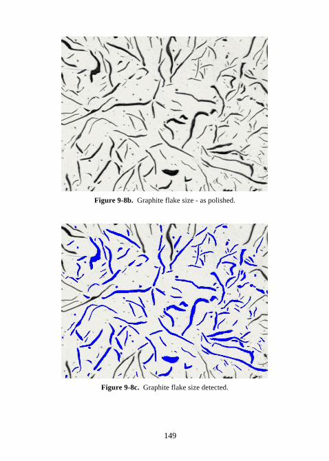
149
Figure 9-8b. Graphite flake size - as polished.
Figure 9-8c. Graphite flake size detected.
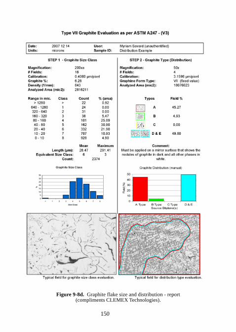
150
Figure 9-8d. Graphite flake size and distribution - report(compliments CLEMEX Technologies).
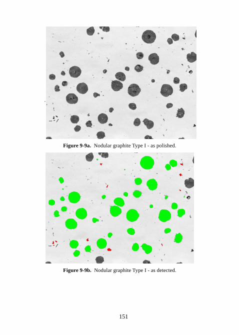
151
.
Figure 9-9a. Nodular graphite Type I - as polished.
Figure 9-9b. Nodular graphite Type I - as detected.
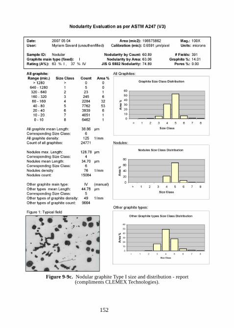
152
Figure 9-9c. Nodular graphite Type I size and distribution - report(compliments CLEMEX Technologies).
153
9.4.4 Porosity (ASTM E562, E1245)
Porosity are voids in the material caused by entrapped air and incomplete orpoor sintering. Porosity can be measured as a volume fraction, eithermanually using ASTM E562 (35) or with automated image analysis usingASTM E1245.
ASTM E562 (Standard Test Method for Determining Volume Fraction bySystematic Manual Point Count) (35) is a point counting method using a clearplastic test grid or an eyepeice reticle with a regular array of test pointsoverlayed on the image. The number of test point falling within the phase orconstituent of interest are counted and divided by the total number of gridpoints.
Pi – point count on the ith field
Pp(i) = P
i/P
T*100% = percentage of grid points, in the constituent observed on
the ith field
PT = total number of points in the test grid (ASTM standard test grits P
T = 16,
25, 49 or 100 points)
n = number of fields counted
t = a multiplier related to the number of fields examined and used in conjunction with the standard deviation of the measurements to determine the 95% CI (see table 1 p. 630 ASTM Standard 3.01, 2010)(35)
Arithmetic average of
s = estimate of the standard deviation
95% CI = 95% confidence interval = t * s /(n) ½
Volume fraction VV = P
p+/- 95% CI
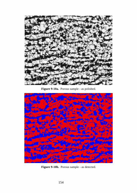
154
Figure 9-10a. Porous sample - as polished.
Figure 9-10b. Porous sample - as detected.
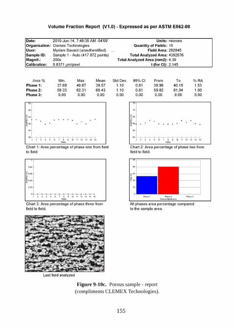
155
Figure 9-10c. Porous sample - report(compliments CLEMEX Technologies).
156
9.4.5 Inclusion rating (ASTM E45)
Inclusions are particles of foreign material that are insoluble in the metal ormaterial matrix. For steels, common inclusions include oxides, sufides orsilicates; however, any foreign substance can be classified as an inclusion.
ASTM E45 (Standard Test Methods for Determining the Inclusion Content ofSteel) (38) is used to characterize the type, size and severity of the inclusionsin wrought steel. ASTM E45 describes the JK-type inclusion rating system.The JK-type inclusion rating system first characterizes the type of inclusion(Type A-D):
Type A-sulfide typeType B-alumina typeType C-silicate typeType D-globular oxide type
Type A and C are very similar in size and shape, however Type A-Sulfide arelight gray which Type S-Silicate are black when viewed under Brightfieldillumination.
Type B stringers consist of a number (at least three) round or angular oxideparticles with aspect ratios less than 2 that are aligned nearly parallel to thedeformation axis.
The second characterization parameter is thickness: designated H-heavy, T-thin.
The third characterization parameter is “Severity Level” and are partitionedbased on the number or length of the particles present in a 0.50 mm2 field ofview (38).
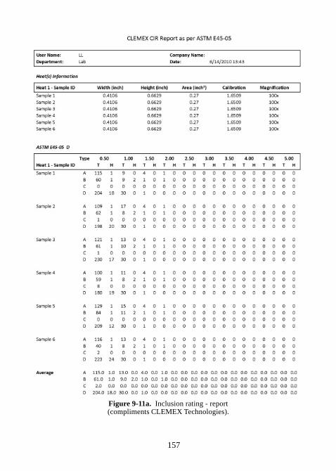
157
Figure 9-11a. Inclusion rating - report(compliments CLEMEX Technologies).
158
9.4.6 Decarburization (ASTM E1077)
Decarburization is the loss of carbon at the metals surface due to chemicalreaction(s) with the contacting media. Decarburization can over timesignificantly change the surface properties of the metal. ASTM E1077(Standard Test Methods for Estimating the Depth of Decarburization of SteelSpecimens) provides the guidelines for estimating the average or greatestdepth of decarburization in hardened or non-hardened steel products (39).
Metallographic analysis of a properly polished and etched sample isconsidered an acceptable technique for determining decarburization forheated-treated, spherodize-annealed, cold-worked, as-hot rolled, as-forged,annealed, or normalized steel specimens. The depth of decarburization can bedetermined by the observed changes in the microstructural cross-section dueto changes in the carbon content.
ASTM defines the following terms (39):Average depth of decarburization – the mean value of 5 or moremeasurements of the total depth of decarburization.
Average free-ferrite depth – the mean value of 5 or more measurements ofthe depth of complete decarburization
Complete decarburization – loss of carbon content at the surface of a steelspecimen to a level below the solubility limit of carbon in ferrite so that onlyferrite is present.
Partial decarburization – loss of carbon content at the surface of a steelspecimen to a level less than the bulk carbon content of the unaffected interiorby greater then the room temperature solubility limit of carbon in ferrite. Thepartial decarburization zone would contain both ferrite and pearlite.
Total depth of decarburization – the perpendicular distance from thespecimen surface to that location in the interior where the bulk carbon contentis reached; that is, the sum of the depths of complete and partialdecarburization. For heat-treated specimens, the presence of non-martensiticstructures in the partially decarburized zone is used to estimate the total depthof decarburization.
Maximum depth of decarburization – the largest measured value of thetotal depth of decarburization.
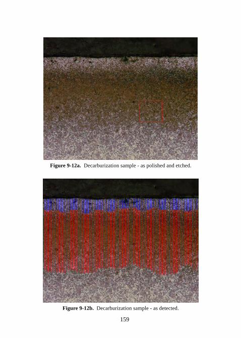
159
Figure 9-12a. Decarburization sample - as polished and etched.
Figure 9-12b. Decarburization sample - as detected.
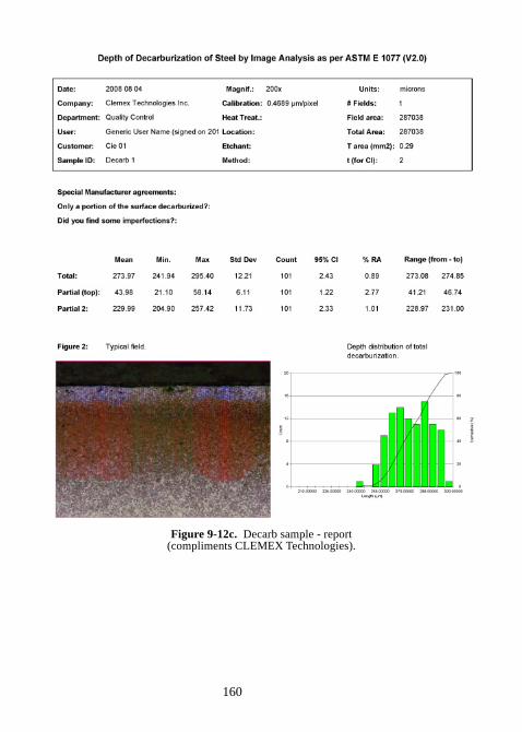
160
Figure 9-12c. Decarb sample - report(compliments CLEMEX Technologies).
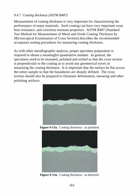
161
9.4.7 Coating thickness (ASTM B487)
Measurement of coating thickness is very important for characterizing theperformance of many materials. Such coating can have very important wear,heat resistance, and corrosion resistant properties. ASTM B487 (StandardTest Method for Measurement of Metal and Oxide Coating Thickness byMicroscopical Examination of Cross Section) describes the recommendedacceptance testing procedures for measuring coating thickness.
As with other metallographic analysis, proper specimen preparation isrequired to obtain a meaningful quantitative number. In general, thespecimens need to be mounted, polished and etched so that the cross sectionis perpendicular to the coating as to avoid any geometrical errors inmeasuring the coating thickness. It is important that the surface be flat acrossthe entire sample so that the boundaries are sharply defined. The crosssection should also be prepared to eliminate deformation, smearing and otherpolishing artifacts.
Figure 9-13a. Coating thickness - as polished.
Figure 9-13a. Coating thickness - as detected.
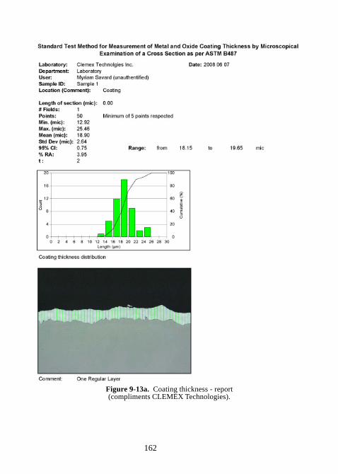
162
Figure 9-13a. Coating thickness - report(compliments CLEMEX Technologies).
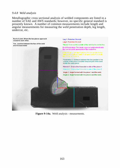
163
9.4.8 Weld analysis
Metallographic cross sectional analysis of welded components are listed in anumber of SAE and AWS standards; however, no specific general standard ispresently known. A number of common measurements include length andangular measurements for measuring the weld penetration depth, leg length,undercut, etc.
Figure 9-14a. Weld analysis - measurments.
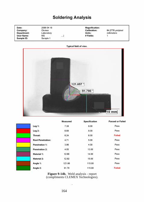
164
Figure 9-14b. Weld analysis - report(compliments CLEMEX Technologies).
.
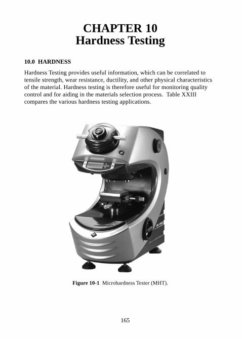
165
CHAPTER 10Hardness Testing
10.0 HARDNESS
Hardness Testing provides useful information, which can be correlated totensile strength, wear resistance, ductility, and other physical characteristicsof the material. Hardness testing is therefore useful for monitoring qualitycontrol and for aiding in the materials selection process. Table XXIIIcompares the various hardness testing applications.
Figure 10-1 Microhardness Tester (MHT).
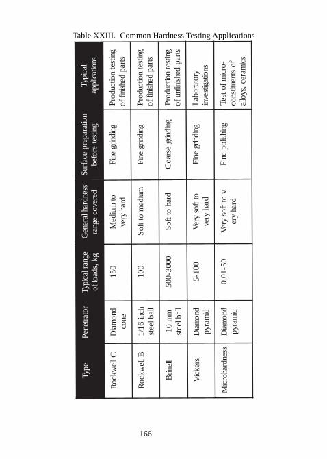
166
Table XXIII. Common Hardness Testing Applications
epyTrotart ene
Pegnar l aci pyT
gk, sdaol f ossendrahl arene
Gderevoc
egnarnoit araper p
ecafruS
gnitseter ofeb
l aci pyTsnoit acil ppa
Cll ewkco
Rdno
maiD
enoc051
otmui de
Mdrah
yrevgni dnirg
eniF
gnitsetnoit cudor
Pstrap
dehsi nif f o
Bll ewkco
Rhcni
61/ 1ll abl eets
001mui de
mot tf o
Sgni dnirg
eniF
gnitsetnoit cudor
Pstrap
dehsi nif f o
ll enirB
mm
01ll abl eets
0003- 005drah
ot tf oS
gni dnirgesrao
Cgnitset
noit cudorP
strapdehsi nifnuf o
srekciV
dnomai
Ddi
maryp001- 5
ot tf osyre
Vdrah
yrevgni dnirg
eniF
yr ot ar obaL
snoit agitsevni
ssendrahorciM
dnomai
Ddi
maryp05- 10. 0
vot tf os
yreV
drahyre
gni hsil openi
F- orci
mf otseTf o
st neutitsnocsci
marec , syoll a
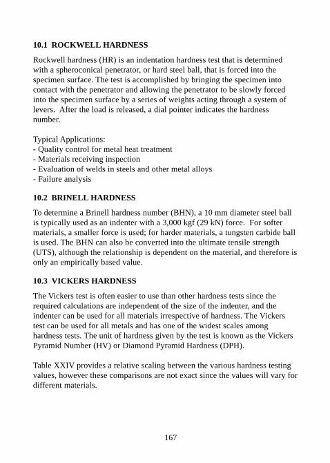
167
10.1 ROCKWELL HARDNESS
Rockwell hardness (HR) is an indentation hardness test that is determinedwith a spheroconical penetrator, or hard steel ball, that is forced into thespecimen surface. The test is accomplished by bringing the specimen intocontact with the penetrator and allowing the penetrator to be slowly forcedinto the specimen surface by a series of weights acting through a system oflevers. After the load is released, a dial pointer indicates the hardnessnumber.
Typical Applications:- Quality control for metal heat treatment- Materials receiving inspection- Evaluation of welds in steels and other metal alloys- Failure analysis
10.2 BRINELL HARDNESS
To determine a Brinell hardness number (BHN), a 10 mm diameter steel ballis typically used as an indenter with a 3,000 kgf (29 kN) force. For softermaterials, a smaller force is used; for harder materials, a tungsten carbide ballis used. The BHN can also be converted into the ultimate tensile strength(UTS), although the relationship is dependent on the material, and therefore isonly an empirically based value.
10.3 VICKERS HARDNESS
The Vickers test is often easier to use than other hardness tests since therequired calculations are independent of the size of the indenter, and theindenter can be used for all materials irrespective of hardness. The Vickerstest can be used for all metals and has one of the widest scales amonghardness tests. The unit of hardness given by the test is known as the VickersPyramid Number (HV) or Diamond Pyramid Hardness (DPH).
Table XXIV provides a relative scaling between the various hardness testingvalues, however these comparisons are not exact since the values will vary fordifferent materials.
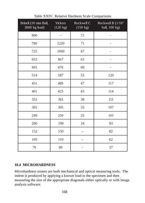
168
Table XXIV. Relative Hardness Scale Comparisons
,llaBmm01(llenirB)daolgk0003
srekciV)gk021(
CllewkcoR)gk051(
"61/1(BllewkcoR)gk001,llab
008 - 27 -
087 0221 17 -
527 0601 76 -
256 768 36 -
106 674 06 -
415 785 35 021
154 984 74 711
104 324 34 411
153 163 83 111
103 503 33 701
942 052 52 101
002 991 61 39
251 051 - 28
501 011 - 26
67 08 - 73
10.4 MICROHARDNESS
Microhardness testers are both mechanical and optical measuring tools. Theindent is produced by applying a known load to the specimen and thenmeasuring the size of the appropriate diagonals either optically or with imageanalysis software.
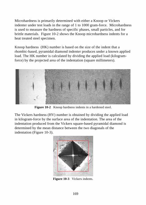
169
Microhardness is primarily determined with either a Knoop or Vickersindenter under test loads in the range of 1 to 1000 gram-force. Microhardnessis used to measure the hardness of specific phases, small particles, and forbrittle materials. Figure 10-2 shows the Knoop microhardness indents for aheat treated steel specimen.
Knoop hardness (HK) number is based on the size of the indent that arhombic-based, pyramidal diamond indenter produces under a known appliedload. The HK number is calculated by dividing the applied load (kilogram-force) by the projected area of the indentation (square millimeters).
Figure 10-2 Knoop hardness indents in a hardened steel.
The Vickers hardness (HV) number is obtained by dividing the applied loadin kilogram-force by the surface area of the indentation. The area of theindentation produced from the Vickers square-based pyramidal diamond isdetermined by the mean distance between the two diagonals of theindentation (Figure 10-3).
Figure 10-3 Vickers indents.
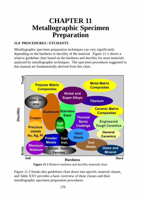
170
CHAPTER 11Metallographic Specimen
Preparation11.0 PROCEDURES / ETCHANTS
Metallographic specimen preparation techniques can vary significantlydepending on the hardness or ductility of the material. Figure 11-1 shows arelative guideline chart based on the hardness and ductility for most materialsanalyzed by metallographic techniques. The specimen procedures suggested inthis manual are fundamentally derived from this chart.
Figure 11-1 Relative hardness and ductility materials chart.
Figure 11-2 breaks this guidelines chart down into specific material classes,and Table XXV provides a basic overview of these classes and theirmetallographic specimen preparation procedures.
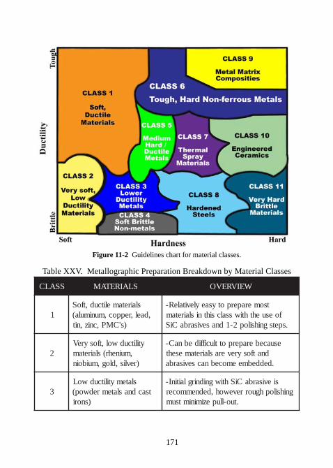
171
Figure 11-2 Guidelines chart for material classes.
Table XXV. Metallographic Preparation Breakdown by Material Classes
SSALC SLAIRETAM WEIVREVO
1slairetamelitcud,tfoS
,dael,reppoc,munimula()s'CMP,cniz,nit
tsomeraperpotysaeylevitaleR-foesuehthtiwssalcsihtnislairetam
.spetsgnihsilop2-1dnasevisarbaCiS
2ytilitcudwol,tfosyreV
,muinehr(slairetam)revlis,dlog,muiboin
esuaceberaperpottluciffidebnaC-dnatfosyreveraslairetameseht
.deddebmeemocebnacsevisarba
3slatemytilitcudwoL
tsacdnaslatemredwop()snori
sievisarbaCiShtiwgnidnirglaitinI-gnihsilophguorrevewoh,dednemmocer
.tuo-llupeziminimtsum
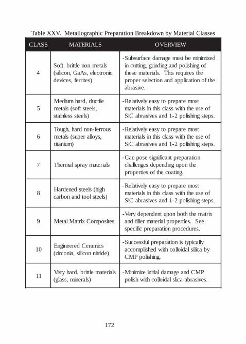
172
Table XXV. Metallographic Preparation Breakdown by Material Classes
SSALC SLAIRETAM WEIVREVO
4slatem-nonelttirb,tfoS
cinortcele,sAaG,nocilis()setirref,secived
deziminimebtsumegamadecafrusbuS-fognihsilopdnagnidnirg,gnittucni
ehtseriuqersihT.slairetamesehtehtfonoitacilppadnanoitcelesreporp
.evisarba
5elitcud,drahmuideM
,sleetstfos(slatem)sleetssselniats
tsomeraperpotysaeylevitaleR-foesuehthtiwssalcsihtnislairetam
.spetsgnihsilop2-1dnasevisarbaCiS
6suorref-nondrah,hguoT
,syollarepus(slatem)muinatit
tsomeraperpotysaeylevitaleR-foesuehthtiwssalcsihtnislairetam
.spetsgnihsilop2-1dnasevisarbaCiS
7 slairetamyarpslamrehTnoitaraperptnacifingisesopnaC-
ehtnopugnidnepedsegnellahc.gnitaocehtfoseitreporp
8hgih(sleetsdenedraH
)sleetslootdnanobrac
tsomeraperpotysaeylevitaleR-foesuehthtiwssalcsihtnislairetam
.spetsgnihsilop2-1dnasevisarbaCiS
9 setisopmoCxirtaMlateMxirtamehthtobnoputnednepedyreV-
eeS.seitreporplairetamrellifdna.serudecorpnoitaraperpcificeps
01scimareCdereenignE
)edirtinnocilis,ainocriz(
yllacipytsinoitaraperplufsseccuS-ybacilisladiollochtiwdehsilpmocca
.gnihsilopPMC
11slairetamelttirb,drahyreV
)slarenim,ssalg(PMCdnaegamadlaitinieziminiM-
.sevisarbaacilsladiollochtiwhsilop
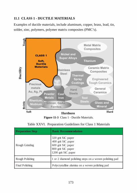
173
11.1 CLASS 1 - DUCTILE MATERIALS
Examples of ductile materials, include aluminum, copper, brass, lead, tin,
solder, zinc, polymers, polymer matrix composites (PMC’s).
Figure 11-3 Class 1 - Ductile Materials.
Table XXVI. Preparation Guidelines for Class 1 Materials
petSnoitaraperP noitadnemmoceRcisaB
gnidnirGhguoR
repapCiStirg023repapCiStirg004repapCiStirg006repapCiStirg008repapCiStirg0021
gnihsiloPhguoR dapgnihsilopnevowanospetsgnihsilopdnomaid2ro1
gnihsiloPlaniF dapgnihsilopnevowanoanimulaenillatsyrcyloP
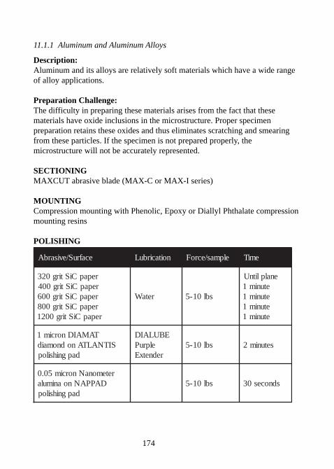
174
11.1.1 Aluminum and Aluminum Alloys
Description:Aluminum and its alloys are relatively soft materials which have a wide rangeof alloy applications.
Preparation Challenge:The difficulty in preparing these materials arises from the fact that thesematerials have oxide inclusions in the microstructure. Proper specimenpreparation retains these oxides and thus eliminates scratching and smearingfrom these particles. If the specimen is not prepared properly, themicrostructure will not be accurately represented.
SECTIONINGMAXCUT abrasive blade (MAX-C or MAX-I series)
MOUNTINGCompression mounting with Phenolic, Epoxy or Diallyl Phthalate compressionmounting resins
POLISHING
ecafruS/evisarbA noitacirbuL elpmas/ecroF emiT
repapCiStirg023repapCiStirg004repapCiStirg006repapCiStirg008repapCiStirg0021
retaW sbl01-5
enalplitnUetunim1etunim1etunim1etunim1
TAMAIDnorcim1SITNALTAnodnomaid
dapgnihsilop
EBULAIDelpruP
rednetxEsbl01-5 setunim2
retemonaNnorcim50.0DAPPANnoanimula
dapgnihsilopsbl01-5 sdnoces03
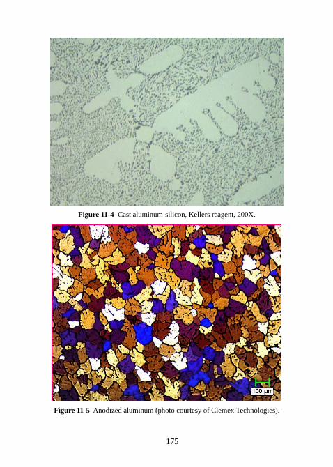
175
Figure 11-4 Cast aluminum-silicon, Kellers reagent, 200X.
Figure 11-5 Anodized aluminum (photo courtesy of Clemex Technologies).
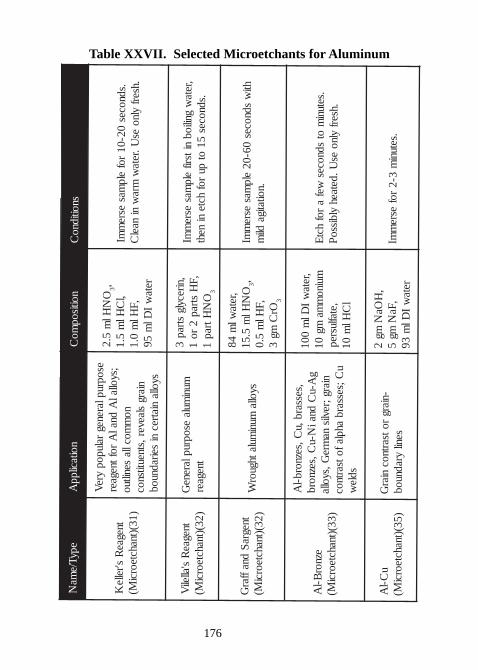
176
Table XXVII. Selected Microetchants for AluminumepyT/e
maN
noitacilppA
noitisopmo
Csnoitidno
C
tnegaeR
s'relleK
)13()tnahcteorciM(
esopruplarenegralupop
yreV
;syollalA
dnalA
roftnegaerno
mmoclla
seniltuoniarg
slaever,stneutitsnocsyolla
niatrecni
seiradnuob
ON
Hlm
5.23,
,lC
Hlm
5.1,F
Hlm
0.1reta
wI
Dlm
59
.sdnoces02-01
rofelp
masesre
mmI
.hserfylno
esU.reta
wmra
wni
naelC
tnegaeR
s'alleliV
)23()tnahcteorciM(
munimula
esopruplareneG
tnegaer
,nirecylgstrap
3,F
Hstrap
2ro
1O
NHtrap
13
,retaw
gniliobnitsrif
elpmas
esrem
mI.sdnoces
51ot
purof
hcteni
neht
tnegraS
dnaffarG
)23()tnahcteorciM(
syollamuni
mulathguorW
,retawl
m48
ON
Hlm
5.513,
,FHl
m5.0
OrC
mg3
3
htiw
sdnoces06-02
elpmas
esrem
mI.noitatiga
dlim
eznorB-l
A)33()tnahcteorci
M(
,sessarb,uC,seznorb-l
Ag
A-uC
dnaiN-u
C,seznorbniarg;revlis
namre
G,syollau
C;sessarbahplafotsartnoc
sdlew
,retaw
IDl
m001
muinom
mamg
01,etaflusrepl
CHl
m01
.setunim
otsdnoces
wefa
rofhct
E.hserf
ylnoes
U.detaehylbisso
P
uC-l
A)53()tnahcteorci
M(-niarg
rotsartnocniar
Gsenil
yradnuob
,H
OaN
mg2
,FaN
mg5
retaw
IDl
m39
.setunim
3-2rof
esrem
mI
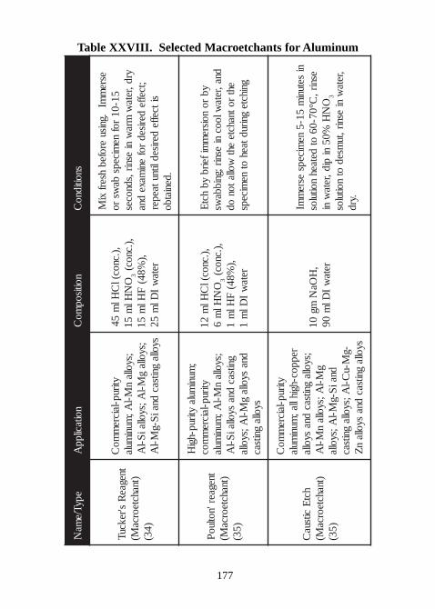
177
Table XXVIII. Selected Macroetchants for Aluminum
epyT/ema
Nnoitacilpp
Anoitisop
moC
snoitidnoC
tnegaeR
s'rekcuT)tnahcteorca
M()43(
ytirup-laicrem
moC
;syollan
M-lA;
munimula
;syollag
M-lA;syollai
S-lA
syollagnitsac
dnaiS-g
M-lA
,).cnoc(lC
Hlm
54O
NHl
m51
3,).cnoc(
,)%84(
FHl
m51
retaw
IDl
m52
esrem
mI.gnisu
erofebhserf
xiM
51-01rof
nemiceps
baws
royrd,reta
wmra
wni
esnir,sdnoces;tceffe
derisedrof
enimaxe
dnasitceffe
derisedlitnutaeper.deniatbo
tnegaer'notluoP
)tnahcteorcaM(
)53 (
;muni
mulaytirup-hgi
Hytirup-laicre
mmoc
;syollan
M-lA;
munimula
gnitsacdna
syollaiS-l
Adna
syollag
M-lA;syolla
syollagnitsac
,).cnoc(lC
Hlm
21O
NHl
m6
3,).cnoc(
,)%84(
FHl
m1
retaw
IDl
m1
ybro
noisrem
mifeirbyb
hctE
dna,retawlooc
niesnir;gnibba
wseht
rotnahcteeht
woll atonod
gnihctegnirudtaeh
otne
miceps
hctE
citsuaC
)tnahcteorcaM(
)53(
ytirup-laicrem
moC
reppoc-hgihlla;muni
mul a;syolla
gnitsacdna
syollag
M-lA;syolla
nM-l
Adnai
S-gM-l
A;syolla-g
M-uC-l
A;syollagnitsac
syollagnitsac
dnasyo lla
nZ
,H
OaN
mg01
retaw
IDl
m09
nisetuni
m51-5
nemiceps
esrem
mIesnir,
C°07-06ot
detaehnoitulos
ON
H%05
nipid,reta
wni
3
,retaw
niesnir,tu
msedot
noitulos.yrd
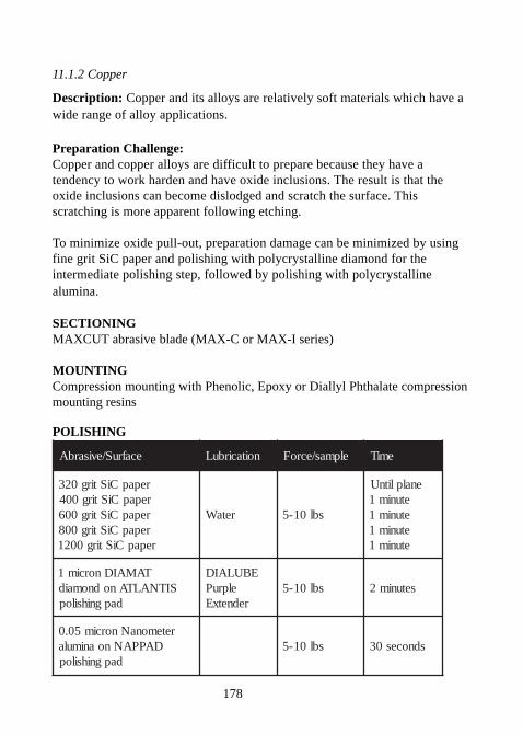
178
11.1.2 Copper
Description: Copper and its alloys are relatively soft materials which have awide range of alloy applications.
Preparation Challenge:Copper and copper alloys are difficult to prepare because they have atendency to work harden and have oxide inclusions. The result is that theoxide inclusions can become dislodged and scratch the surface. Thisscratching is more apparent following etching.
To minimize oxide pull-out, preparation damage can be minimized by usingfine grit SiC paper and polishing with polycrystalline diamond for theintermediate polishing step, followed by polishing with polycrystallinealumina.
SECTIONINGMAXCUT abrasive blade (MAX-C or MAX-I series)
MOUNTINGCompression mounting with Phenolic, Epoxy or Diallyl Phthalate compressionmounting resins
POLISHING
ecafruS/evisarbA noitacirbuL elpmas/ecroF emiT
repapCiStirg023repapCiStirg004repapCiStirg006repapCiStirg008repapCiStirg0021
retaW sbl01-5
enalplitnUetunim1etunim1etunim1etunim1
TAMAIDnorcim1SITNALTAnodnomaid
dapgnihsilop
EBULAIDelpruP
rednetxEsbl01-5 setunim2
retemonaNnorcim50.0DAPPANnoanimula
dapgnihsilopsbl01-5 sdnoces03
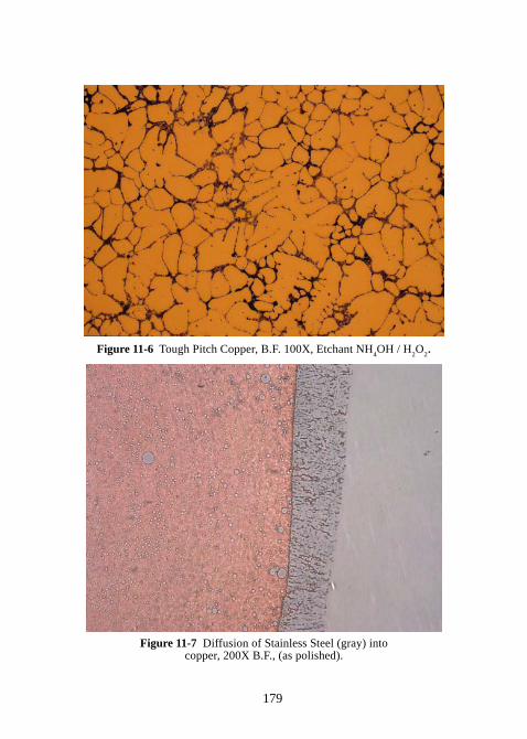
179
Figure 11-6 Tough Pitch Copper, B.F. 100X, Etchant NH4OH / H
2O
2.
Figure 11-7 Diffusion of Stainless Steel (gray) intocopper, 200X B.F., (as polished).
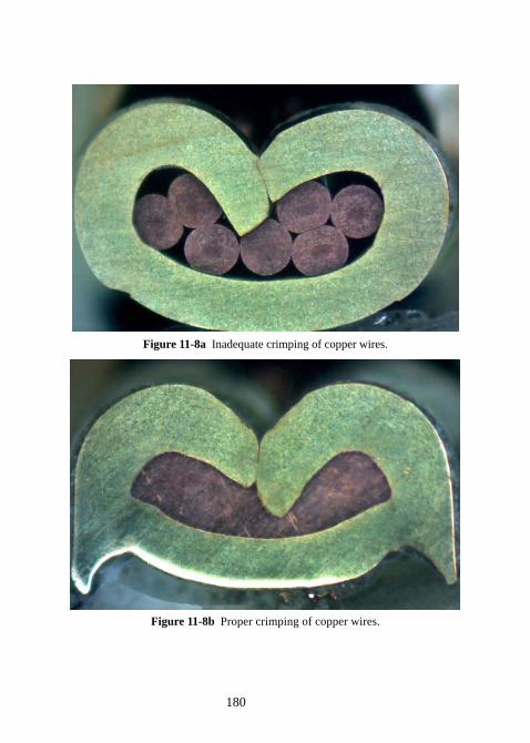
180
Figure 11-8a Inadequate crimping of copper wires.
Figure 11-8b Proper crimping of copper wires.
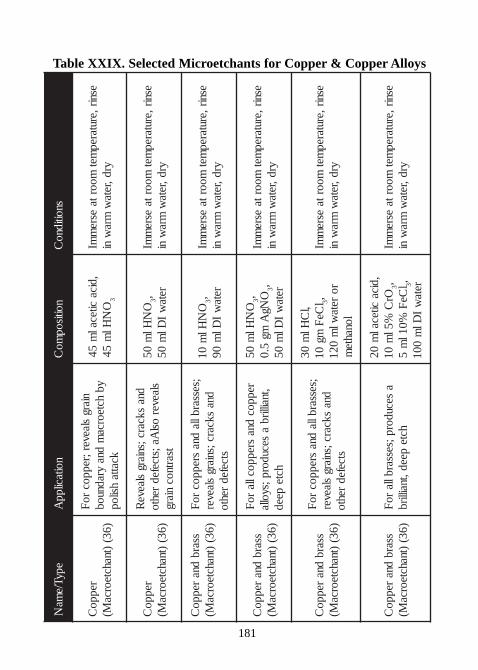
181
Table XXIX. Selected Microetchants for Copper & Copper Alloys
s
epyT/ema
Nnoitacilpp
Anoitisop
moC
snoitidnoC
reppoC
)63()tnahcteorca
M(
niargslaever;reppoc
roF
ybhcteorca
mdna
yradnuobkcatta
hsilop
,dicaciteca l
m54
ON
Hlm
543
esnir,erutarepmet
moortaesre
mmI
yrd,retaw
mraw
ni
reppoC
)63()tnahcteorca
M(
dnaskcarc;sniarg
slaeveR
slaeveros l
Aa;stcefedrehto
tsartnocniarg
ON
Hlm
053,
retaw
IDl
m05
esnir,erutarepmet
moortaesre
mmI
yrd,retaw
mraw
ni
ssarbdna
reppoC
)63()tnahcteorca
M(;sessarblla
d nasreppoc
roF
dnaskcarc;sniarg
slaeverstcefed
rehto
ON
Hlm
013,
retaw
IDl
m09
esnir,erutarepmet
moortaesre
mmI
yrd,retaw
mraw
ni
ssarbdna
reppoC
)63()tnahcteorca
M(
reppocdna
sre ppocllaro
F,tnaillirb
asecudorp;syolla
hctepeed
ON
Hlm
053, O
NgA
mg5.0
3, retaw
IDl
m05
esnir,erutarepmet
moortaesre
mmI
yrd,retaw
mraw
ni
ssarbdna
reppoC
)63()tnahcteorca
M(
;sessarbllad na
sreppocro
Fdna
skcarc;sniargslaever
stcefedrehto
,lC
Hlm
03l
CeF
mg01
3,ro
retawl
m021
lonahtem
esnir,erutarepmet
moortaesre
mmI
yrd,retaw
mraw
ni
ssarbdna
reppoC
)63()tnahcteorca
M(a
se cudorp;sessarbllaro
Fhcte
peed,tnaillirb
,dicacitecal
m02
OrC
%5lm
013, l
CeF
%01lm
53, reta
wI
Dlm
001
esnir,erutarepmet
moortaesre
mmI
yrd,retaw
mraw
ni
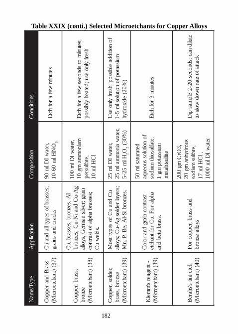
182
Table XXIX (conti.) Selected Microetchants for Copper AlloysepyT/e
maN
noitacilppA
noitisopmo
Csnoitidno
C
ssarB
dnareppo
C)73(
)tnahcteorciM(
;sessarbfosepytlla
dnau
Cskcarc
dnasniarg
,retaw
IDl
m09
ON
Hlm
06-0 13
setunim
wefa
rofhct
E
,ssarb,reppoC
eznorb)83(
)tnahcteorciM(
lA,seznorb,sessarb,u
Cg
A-uC
dnaiN-u
C,seznorbniarg;revlis
namre
G,syolla;sessarb
ahplafotsartnoc.sdle
wu
C
,retaw
IDl
m001
muinom
mamg
01,etaflusrepl
CHl
m01
;setun im
otsdnoces
wefa
rofhct
Ehserf
ylnoesu;detaeh
ylbissop
,redlos,reppoC
eznorb,ssarb)93(
)tnahcteorciM(
uC
dnau
Cfosepyttso
M;sreyal
redlosg
A-uC;syolla
.seznorbiS-l
A,eB,P,n
M
,retaw
IDl
m52
,retaw
ainom
malm
52Hl
m52-5
2O2
)%03(
fonoitidda
elbissop;hserfylno
esU
muissatopfonoitulosl
m5-1
)%02(
edixordyh
-tnegaers'
mmel
K)93(
)tnahcteorciM(
tsartnocniarg
dnarolo
Cahpla
roF.u
Croftnahcte
.ssarbateb
dna
detarutaslm
05fo
noitulossuoeuqa
,etaflusoihtmuidos
muissatopmg
1etiflusibate
m
setunim
3rof
hctE
hctetnits'share
B)04(
)tnahcteorciM(
dnassarb,reppoc
roF
syollaeznorb
,3Or
Cmg
002suordyhna
mg02
,etaflusmuidos
,lC
Hlm
71reta
wI
Dlm
0001
etulidnac;sdnoces
02-2elp
maspi
Dkc attafo
etarn
wodwols
ot
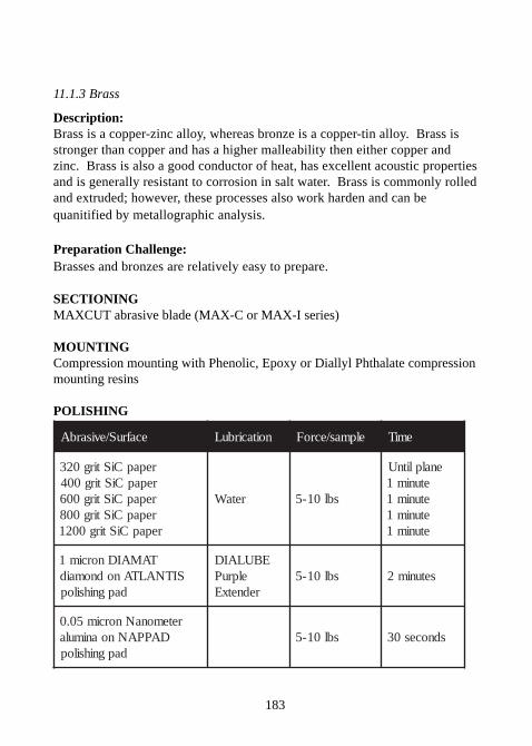
183
11.1.3 Brass
Description:Brass is a copper-zinc alloy, whereas bronze is a copper-tin alloy. Brass isstronger than copper and has a higher malleability then either copper andzinc. Brass is also a good conductor of heat, has excellent acoustic propertiesand is generally resistant to corrosion in salt water. Brass is commonly rolledand extruded; however, these processes also work harden and can bequanitified by metallographic analysis.
Preparation Challenge:Brasses and bronzes are relatively easy to prepare.
SECTIONINGMAXCUT abrasive blade (MAX-C or MAX-I series)
MOUNTINGCompression mounting with Phenolic, Epoxy or Diallyl Phthalate compressionmounting resins
POLISHING
ecafruS/evisarbA noitacirbuL elpmas/ecroF emiT
repapCiStirg023repapCiStirg004repapCiStirg006repapCiStirg008repapCiStirg0021
retaW sbl01-5
enalplitnUetunim1etunim1etunim1etunim1
TAMAIDnorcim1SITNALTAnodnomaid
dapgnihsilop
EBULAIDelpruP
rednetxEsbl01-5 setunim2
retemonaNnorcim50.0DAPPANnoanimula
dapgnihsilopsbl01-5 sdnoces03
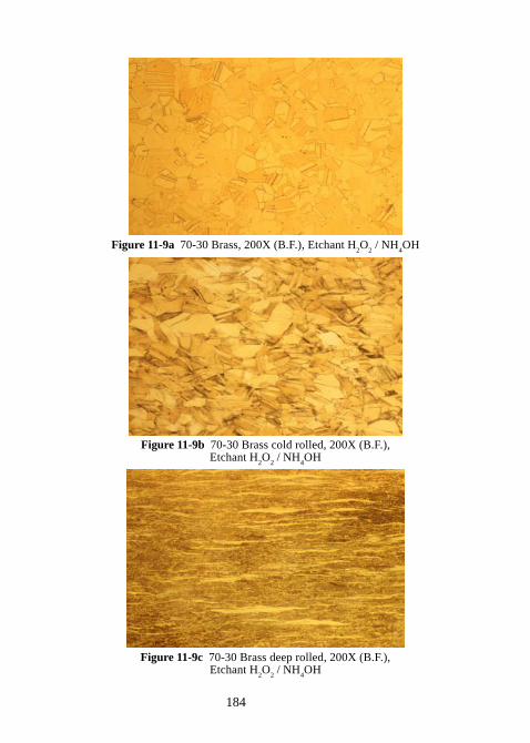
184
Figure 11-9a 70-30 Brass, 200X (B.F.), Etchant H2O
2 / NH
4OH
Figure 11-9b 70-30 Brass cold rolled, 200X (B.F.),Etchant H
2O
2 / NH
4OH
Figure 11-9c 70-30 Brass deep rolled, 200X (B.F.),Etchant H
2O
2 / NH
4OH
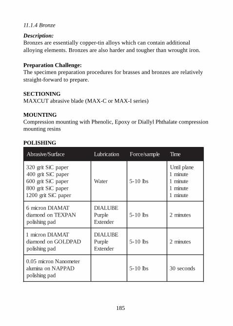
185
11.1.4 Bronze
Description:Bronzes are essentially copper-tin alloys which can contain additionalalloying elements. Bronzes are also harder and tougher than wrought iron.
Preparation Challenge:The specimen preparation procedures for brasses and bronzes are relativelystraight-forward to prepare.
SECTIONINGMAXCUT abrasive blade (MAX-C or MAX-I series)
MOUNTINGCompression mounting with Phenolic, Epoxy or Diallyl Phthalate compressionmounting resins
POLISHING
ecafruS/evisarbA noitacirbuL elpmas/ecroF emiT
repapCiStirg023repapCiStirg004repapCiStirg006repapCiStirg008repapCiStirg0021
retaW sbl01-5
enalplitnUetunim1etunim1etunim1etunim1
TAMAIDnorcim6NAPXETnodnomaid
dapgnihsilop
EBULAIDelpruP
rednetxEsbl01-5 setunim2
TAMAIDnorcim1DAPDLOGnodnomaid
dapgnihsilop
EBULAIDelpruP
rednetxEsbl01-5 setunim2
retemonaNnorcim50.0DAPPANnoanimula
dapgnihsilopsbl01-5 sdnoces03
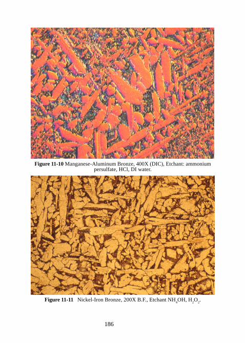
186
Figure 11-10 Manganese-Aluminum Bronze, 400X (DIC), Etchant: ammoniumpersulfate, HCl, DI water.
Figure 11-11 Nickel-Iron Bronze, 200X B.F., Etchant NH4OH, H
2O
2.
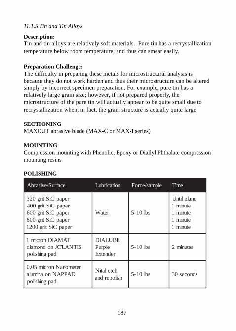
187
11.1.5 Tin and Tin Alloys
Description:Tin and tin alloys are relatively soft materials. Pure tin has a recrystallizationtemperature below room temperature, and thus can smear easily.
Preparation Challenge:The difficulty in preparing these metals for microstructural analysis isbecause they do not work harden and thus their microstructure can be alteredsimply by incorrect specimen preparation. For example, pure tin has arelatively large grain size; however, if not prepared properly, themicrostructure of the pure tin will actually appear to be quite small due torecrystallization when, in fact, the grain structure is actually quite large.
SECTIONINGMAXCUT abrasive blade (MAX-C or MAX-I series)
MOUNTINGCompression mounting with Phenolic, Epoxy or Diallyl Phthalate compressionmounting resins
POLISHING
ecafruS/evisarbA noitacirbuL elpmas/ecroF emiT
repapCiStirg023repapCiStirg004repapCiStirg006repapCiStirg008repapCiStirg0021
retaW sbl01-5
enalplitnUetunim1etunim1etunim1etunim1
TAMAIDnorcim1SITNALTAnodnomaid
dapgnihsilop
EBULAIDelpruP
rednetxEsbl01-5 setunim2
retemonaNnorcim50.0DAPPANnoanimula
dapgnihsilop
hctelatiNhsiloperdna
sbl01-5 sdnoces03
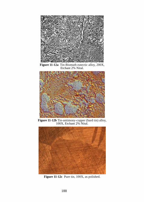
188
Figure 11-12a Tin-Bismuth eutectic alloy, 200X,Etchant 2% Nital.
Figure 11-12b Tin-antimony-copper (hard tin) alloy,100X, Etchant 2% Nital.
Figure 11-12c Pure tin, 100X, as polished.
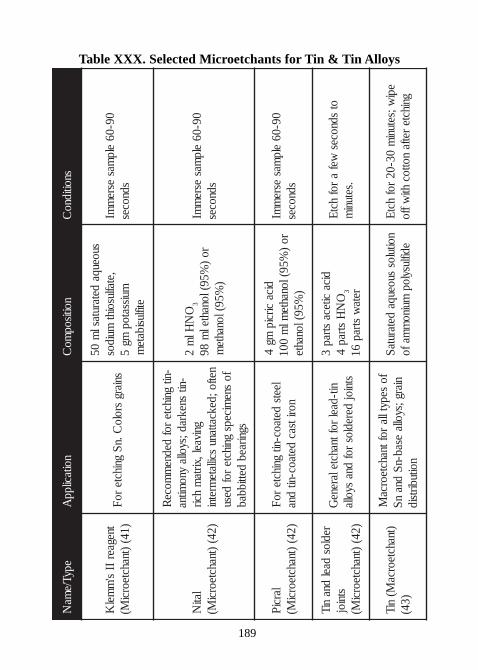
189
Table XXX. Selected Microetchants for Tin & Tin AlloysepyT/e
maN
noitacilppA
noitisopmo
Csnoitidno
C
tnegaerII
s'm
melK
)14()tnahcteorci
M(sniarg
sroloC.nS
gnihcteroF
suoeuqadetarutasl
m05
,etaflusoihtmuidos
muissatopmg
5etiflusibate
m
09-06elp
masesre
mmI
sdnoces
latiN
)24()tnahcteorci
M(
-nitgnihcte
rofdedne
mmoce
R-nit
snekrad;syollayno
mitnagnivael,xirta
mhcir
netfo;dekcattanuscillate
mretnifo
snemiceps
gnihcterof
desusgniraeb
dettibbab
ON
Hlm
23
ro)
%59(lonahtelm
89)
%59(lonahtem
09-06elp
masesre
mmI
sdnoces
larciP)24(
)tnahcteorciM(
leetsdetaoc-nit
gnihcteroF
noritsacdetaoc-nit
dna
dicacircip
mg4
ro)
%59(lonahteml
m001
)%59(lonahte
09-06elp
masesre
mmI
sdnoces
redlosdael
dnaniT
stnioj)24(
)tnahcteorciM(
nit-daelroftnahctelarene
Gstnioj
deredlosrof
dnasyolla
dicaciteca
strap3
ON
Hstrap
43 reta
wstrap
61
otsdnoces
wefa
rofhctE
.setunim
)tnahcteorcaM(
niT)34(
fosepytlla
roftnahcteorcaM
niarg;syollaesab-nS
dnanS
noitubirtsid
noitulossuoeuqa
detarutaSediflusylop
muinom
mafoepi
w;setunim
03-02rof
hctEgnihcte
retfanottoc
htiwffo
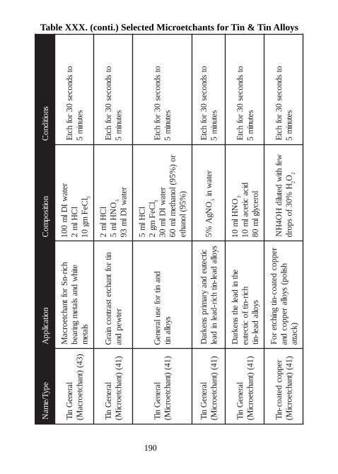
190
Table XXX. (conti.) Selected Microetchants for Tin & Tin Alloys
epyT/ema
Nnoitacilpp
Anoitisop
moC
snoitidnoC
lareneG
niT)34(
)tnahcteorcaM(
hcir-nS
roftnahcteorcaM
etihw
dnaslate
mgniraeb
slatem
retaw
IDl
m001
lC
Hlm
2l
CeF
mg01
3
otsdnoces
03rof
hctE
setunim
5
lareneG
niT)14(
)tnahcteorciM(
nitroftnahctetsartnoc
niarG
retwep
dna
lC
Hlm
2O
NHl
m5
3
retaw
IDl
m39
otsdnoces
03rof
hctE
setunim
5
lareneG
niT)14(
)tnahcteorciM(
dnanit
rofesularene
Gsyolla
nit
lC
Hlm
5l
C eF
mg2
3
retaw
IDl
m03
ro)
%59(lonahteml
m06
)%59(lonahte
otsdnoces
03rof
hctE
setunim
5
lareneG
niT)14(
)tnahcteorciM(
citce tuedna
yramirp
snekraD
syolladael-nit
hcir-daelni
daelO
NgA
%53
retaw
niot
sdnoces03
rofhct
Esetuni
m5
lareneG
niT)14(
)tnahcteorciM(
ehtni
daeleht
snekraD
hcir-nitfocitcetue
syo lladael-nit
ON
Hlm
013
dicacitecal
m01
lorecylglm
08
otsdnoces
03rof
hctE
setunim
5
reppocdetaoc-niT
)14()tnahcteorci
M(
reppocdetaoc-ni t
gnihctero
Fhsilop(
syollareppoc
dna)kcatta
wefhti
wdetulid
HO4
HN
H%03fo
spord2O
2
otsdnoces
03rof
hctE
setunim
5
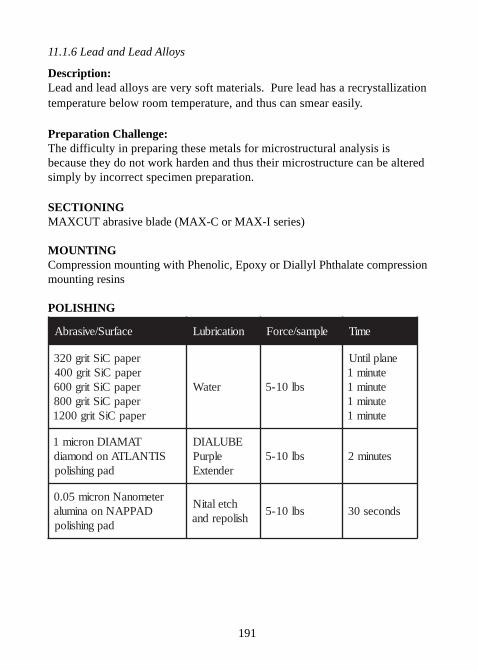
191
11.1.6 Lead and Lead Alloys
Description:Lead and lead alloys are very soft materials. Pure lead has a recrystallizationtemperature below room temperature, and thus can smear easily.
Preparation Challenge:The difficulty in preparing these metals for microstructural analysis isbecause they do not work harden and thus their microstructure can be alteredsimply by incorrect specimen preparation.
SECTIONINGMAXCUT abrasive blade (MAX-C or MAX-I series)
MOUNTINGCompression mounting with Phenolic, Epoxy or Diallyl Phthalate compressionmounting resins
POLISHING
ecafruS/evisarbA noitacirbuL elpmas/ecroF emiT
repapCiStirg023repapCiStirg004repapCiStirg006repapCiStirg008repapCiStirg0021
retaW sbl01-5
enalplitnUetunim1etunim1etunim1etunim1
TAMAIDnorcim1SITNALTAnodnomaid
dapgnihsilop
EBULAIDelpruP
rednetxEsbl01-5 setunim2
retemonaNnorcim50.0DAPPANnoanimula
dapgnihsilop
hctelatiNhsiloperdna
sbl01-5 sdnoces03
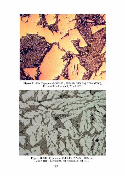
192
Figure 11-13a Type metal (54% Pb, 28% Sb, 18% Sn), 200X (DIC),Etchant 90 ml ethanol, 20 ml HCl.
Figure 11-13b Type metal (54% Pb, 28% Sb, 18% Sn),200X (BF), Etchant 90 ml ethanol, 20 ml HCl.
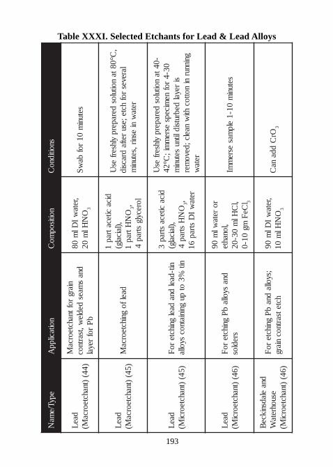
193
Table XXXI. Selected Etchants for Lead & Lead Alloys
epyT/ema
Nnoitacilpp
Anoitisop
moC
snoitidnoC
daeL
)44()tnahcteorca
M(
niargroftnahcteorca
Mdna
smaes
dedlew,tsartnoc
bP
rofreyal
,retaw
IDl
m08
ON
Hlm
023
setunim
01rof
baw
S
daeL
)54()tnahcteorca
M(daelfo
gnihcteorcaM
dicacitecatrap
1,)laicalg(
ON
Htrap1
3,lorecylg
strap4
,C°08ta
noitulosderaperp
ylhserfes
Ulareves
rofhcte;esu
retfadracsid
retaw
niesnir,setuni
m
daeL
)54()tnahcteorci
M(nit-dael
dnadael
gnihctero
Fnit
%3ot
pugniniatnoc
syolla
dicaciteca
strap3
,)laicalg(O
NH
str ap4
3,reta
wI
Dstrap
61
-04tanoitulos
deraperpylhserf
esU
03-4rof
nemiceps
esrem
mi;C°24
sireyal
debrutsidlitnusetuni
mgninnur
ninottoc
htiw
naelc;devomer
retaw
daeL
)64()tnahcteorci
M(dna
syollab
Pgnihcte
roF
sredlos
roreta
wlm
09,lonahte
,lC
Hlm
03-02l
CeF
mg01-0
3
setunim
01-1elp
masesre
mmI
dnaeladsnikce
Besuohreta
W)64(
)tnahcteorciM(
;syolladna
bP
gnihctero
Fhctetsartnoc
niarg,reta
wI
Dlm
09O
NHl
m01
3
OrC
ddana
C3
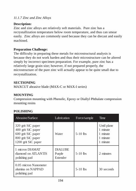
194
11.1.7 Zinc and Zinc Alloys
Description:Zinc and zinc alloys are relatively soft materials. Pure zinc has arecrystallization temperature below room temperature, and thus can smeareasily. Zinc alloys are commonly used because they can be diecast and easilymachined.
Preparation Challenge:The difficulty in preparing these metals for microstructural analysis isbecause they do not work harden and thus their microstructure can be alteredsimply by incorrect specimen preparation. For example, pure zinc has arelatively large grain size; however, if not prepared properly, themicrostructure of the pure zinc will actually appear to be quite small due torecrystallization.
SECTIONINGMAXCUT abrasive blade (MAX-C or MAX-I series)
MOUNTINGCompression mounting with Phenolic, Epoxy or Diallyl Phthalate compressionmounting resins
POLISHING
ecafruS/evisarbA noitacirbuL elpmas/ecroF emiT
repapCiStirg023repapCiStirg004repapCiStirg006repapCiStirg008repapCiStirg0021
retaW sbl01-5
enalplitnUetunim1etunim1etunim1etunim1
TAMAIDnorcim1SITNALTAnodnomaid
dapgnihsilop
EBULAIDelpruP
rednetxEsbl01-5 setunim2
retemonaNnorcim50.0DAPPANnoanimula
dapgnihsilopsbl01-5 sdnoces03
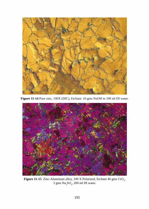
195
Figure 11-14 Pure zinc, 100X (DIC), Etchant: 10 gms NaOH in 100 ml DI water.
Figure 11-15 Zinc-Aluminum alloy, 100 X Polarized, Etchant 40 gms CrO3,
3 gms Na2SO
4, 200 ml DI water.
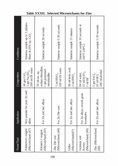
196
Table XXXII. Selected Microetchants for ZincepyT/e
maN
noitacilppA
noitisopmo
Csnoitidno
C
tnegaers'notre
mlaP
)74()tnahcteorci
M(dna
nZ
eruprof
ralupopyre
Vsyolla
OrC
mg04
3,a
Nmg
32
OS
4,reta
wI
Dlm
002
.setunim
3ot
puelp
masesre
mmI
OrC.qa
%02ni
esniR
3
tnegaerI
s'm
melK
)74()tnahcteorci
M(syolla
cnizdna
nZ
roF
.qa.taslm
05,etaflusoiht
muidosmuissatop
mg1
etiflusibatem
sdnoces03
elpmas
esrem
mI
tsacei
Dcni
Z)84(
)tnahcteorciM(
tsac-eiD
nZ
roF
ON
Hlm
53,
retaw
IDl
m001
sdnoces03-5
elpmas
esrem
mI
selleG
)74()tnahcteorciM(
syollacniz
dnan
Zro
F,dica
citcallm
89O
NHl
m2
3
setunim
51elp
masesre
mmI
dnaenonne
Gyesre
K)94(
)tnahcteorciM(
niargslaever;syolla
nZ
roF
seiradnuob
,retawl
m48
Hlm
512
OS
4,F
Hlm
1
tasdnoces
01elp
masesre
mmI
)C°83(
F°001
)tnahcteorciM(
cniZ
)94(syolla
cnizdna
nZ
roF
lCe
Fmg
53, ,l
CHl
m01
lohoclalm
042sdnoces
03-5elp
masesre
mmI
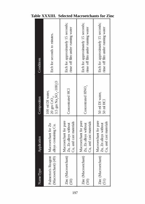
197
Table XXXIII. Selected Macroetchants for Zinc
epyT/ ema
Nnoit acil pp
Anoitisop
moC
snoiti dnoC
t negaeR
s' notreml a
P) 94(
)t nahct eorcaM(
nZ
r of t nahct eorcaM
. uC
gni ni at nocsyoll a
,ret aw
IDl
m001
OrC
mg02
3,a
Nmg
5. 32
OS
4H01-
2O. set uni
mot
sdnocesr of
hctE
)t nahct eorcaM(
cniZ
) 05(
erupr of t nahct eorca
Mt uohti
wsyoll a
nZ, n
Zsl airet a
mtsacdna, u
Cl
CH
det art necnoC
;sdnoces51
yl et ami xor ppa
r ofhct
Eret a
wgni nnur
rednumlif ff o
esnir
)t nahct eorcaM(
cniZ
) 05(
erupr of t nahct eorca
Mt uohti
wsyoll a
nZ, n
Zsl airet a
mtsacdna, u
CO
NH
det art necnoC
3
;sdnoces51
yl et ami xor ppa
r ofhct
Eret a
wgni nnur
rednumlif ff o
esnir
)t nahct eorcaM(
cniZ
) 15(
erupr of t nahct eorca
Mtuohti
wsyoll a
nZ, n
Zsl airet a
mtsacdna, u
C
,ret aw
IDl
m05
lC
Hlm
05;sdnoces
51yl et a
mi xor ppar of
hctE
ret aw
gni nnurrednu
mlif ff oesnir
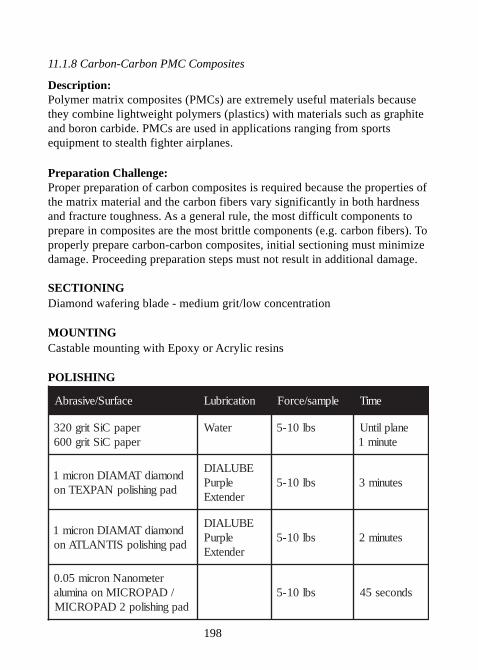
198
11.1.8 Carbon-Carbon PMC Composites
Description:Polymer matrix composites (PMCs) are extremely useful materials becausethey combine lightweight polymers (plastics) with materials such as graphiteand boron carbide. PMCs are used in applications ranging from sportsequipment to stealth fighter airplanes.
Preparation Challenge:Proper preparation of carbon composites is required because the properties ofthe matrix material and the carbon fibers vary significantly in both hardnessand fracture toughness. As a general rule, the most difficult components toprepare in composites are the most brittle components (e.g. carbon fibers). Toproperly prepare carbon-carbon composites, initial sectioning must minimizedamage. Proceeding preparation steps must not result in additional damage.
SECTIONINGDiamond wafering blade - medium grit/low concentration
MOUNTINGCastable mounting with Epoxy or Acrylic resins
POLISHING
ecafruS/evisarbA noitacirbuL elpmas/ecroF emiT
repapCiStirg023repapCiStirg006
retaW sbl01-5 enalplitnUetunim1
dnomaidTAMAIDnorcim1dapgnihsilopNAPXETno
EBULAIDelpruP
rednetxEsbl01-5 setunim3
dnomaidTAMAIDnorcim1dapgnihsilopSITNALTAno
EBULAIDelpruP
rednetxEsbl01-5 setunim2
retemonaNnorcim50.0/DAPORCIMnoanimula
dapgnihsilop2DAPORCIMsbl01-5 sdnoces54
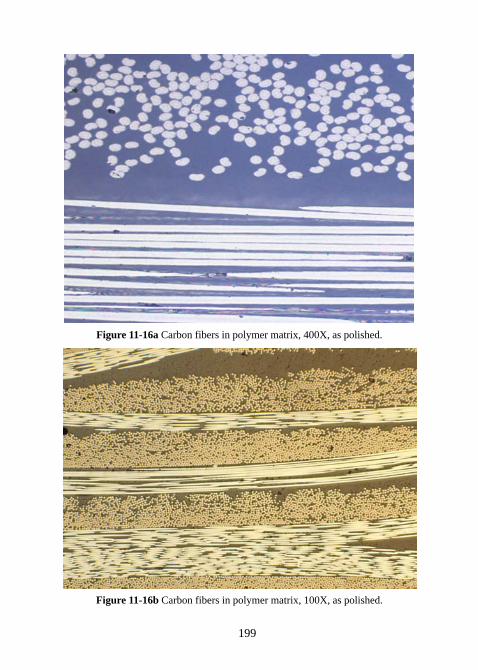
199
Figure 11-16a Carbon fibers in polymer matrix, 400X, as polished.
Figure 11-16b Carbon fibers in polymer matrix, 100X, as polished.
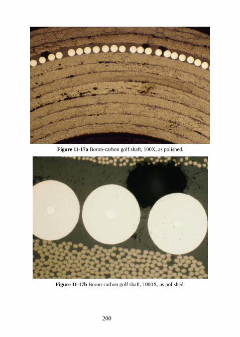
200
Figure 11-17a Boron-carbon golf shaft, 100X, as polished.
Figure 11-17b Boron-carbon golf shaft, 1000X, as polished.
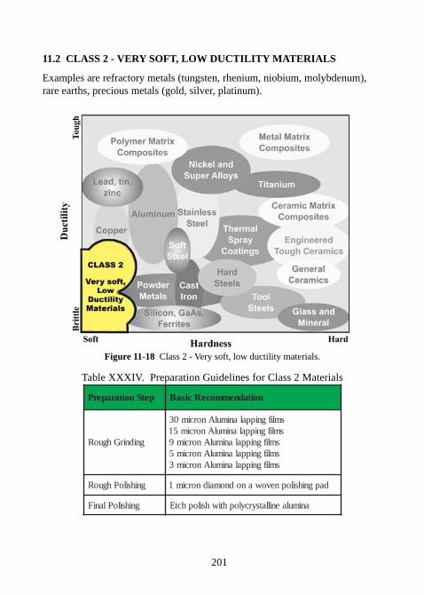
201
11.2 CLASS 2 - VERY SOFT, LOW DUCTILITY MATERIALS
Examples are refractory metals (tungsten, rhenium, niobium, molybdenum),rare earths, precious metals (gold, silver, platinum).
Figure 11-18 Class 2 - Very soft, low ductility materials.
Table XXXIV. Preparation Guidelines for Class 2 Materials
petSnoitaraperP noitadnemmoceRcisaB
gnidnirGhguoR
smlifgnippalanimulAnorcim03smlifgnippalanimulAnorcim51
smlifgnippalanimulAnorcim9smlifgnippalanimulAnorcim5smlifgnippalanimulAnorcim3
gnihsiloPhguoR dapgnihsilopnevowanodnomaidnorcim1
gnihsiloPlaniF animulaenillatsyrcylophtiwhsilophctE
202
11.2.1 Refractory Materials (Rhenium, Niobium, Tungsten)
Description:Refractory metals such as rhenium, niobium and tungsten have very highmelting temperatures; however, they are typically very soft.
Preparation Challenge:Since refractory metals are very soft, any loose or fractured abrasive particlescan easily embed. This makes specimen preparation very difficult because itgums up diamond grinding disks or specimen can become embedded withfractured SiC particles when ground with SiC papers. The key to preparationof these materials is to use tougher alumina abrasives and to chemically etchthe specimen in between each grinding step. The purpose of etching is toremove the embedded particles so as not to carry them over to the nextgrinding step as contamination.
SECTIONINGMAXCUT abrasive blade (MAX-C or MAX-I series)
MOUNTINGCompression mounting with Phenolic, Epoxy or Diallyl Phthalate compressionmounting resins
POLISHING
ecafruS/evisarbA noitacirbuL elpmas/ecroF emiT
mlifanimulanorcim03mlifanimulanorcim51
mlifanimulanorcim9mlifanimulanorcim5mlifanimulanorcim3
retaW sbl01-5
enalplitnUetunim1etunim1etunim1etunim1
TAMAIDnorcim1SITNALTAnodnomaid
dapgnihsilop
elpruPEBULAIDrednetxE
sbl01-5 etunim1
cidicanorcim50.0noanimularetemonaN
2MEHCKCALBdapgnihsilop
detulid%01ddAetanretla;tnahctegnihsilopneewteb
gnihctedna
sbl01-5 sdnoces03
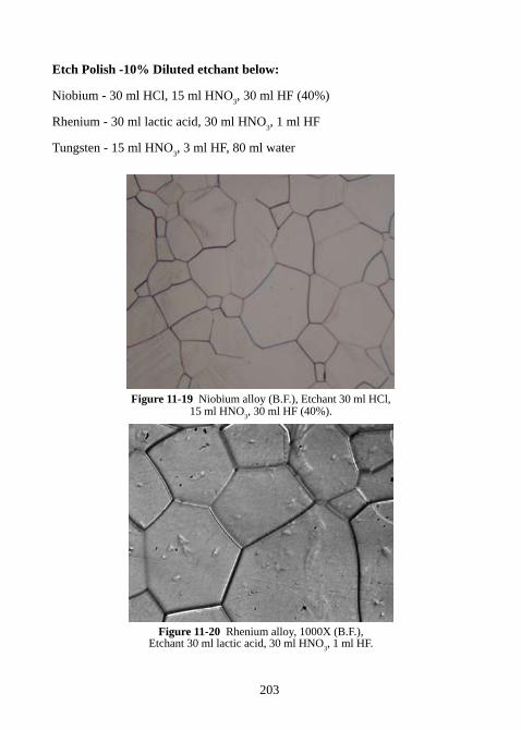
203
Etch Polish -10% Diluted etchant below:
Niobium - 30 ml HCl, 15 ml HNO3, 30 ml HF (40%)
Rhenium - 30 ml lactic acid, 30 ml HNO3, 1 ml HF
Tungsten - 15 ml HNO3, 3 ml HF, 80 ml water
Figure 11-19 Niobium alloy (B.F.), Etchant 30 ml HCl,15 ml HNO
3, 30 ml HF (40%).
Figure 11-20 Rhenium alloy, 1000X (B.F.),Etchant 30 ml lactic acid, 30 ml HNO
3, 1 ml HF.
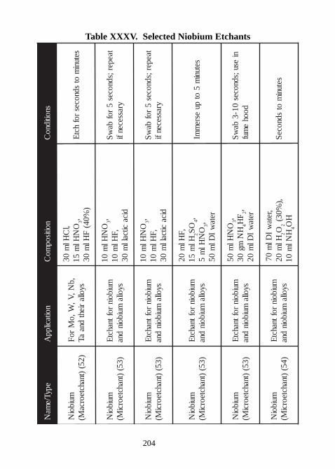
204
Table XXXV. Selected Niobium EtchantsepyT/ e
maN
noit acil ppA
noitisopmo
Csnoiti dno
C
mui boiN
) 25()t nahct eorca
M(, b
N,V,
W, oM
r oF
syoll ari eht
dnaaT
,lC
Hlm
03O
NHl
m51
3,)
%04(F
Hlm
03set uni
mot
sdnocesr of
hctE
mui boiN
) 35()t nahct eorci
M(mui boi n
r of t nahctE
syoll amui boi n
dna
ON
Hlm
013,
, FHl
m01
di cacit cal l
m03
t aeper ;sdnoces5
r ofba
wS
yrassecenfi
mui boiN
) 35()t nahct eorci
M(mui boi n
r of t nahctE
syoll amui boi n
dna
ON
Hlm
013,
, FHl
m01
di cacit cal l
m03
t aeper ;sdnoces5
r ofba
wS
yrassecenfi
mui boiN
) 35()t nahct eorci
M(mui boi n
r of t nahctE
syoll amui boi n
dna
, FHl
m02
Hlm
512
OS
4,O
NHl
m5
3,ret a
wI
Dlm
05
set unim
5ot
puesre
mmI
mui boiN
) 35()t nahct eorci
M(mui boi n
r of t nahctE
syoll amui boi n
dna
ON
Hlm
053,
HN
mg03
4F
H2, ret a
wI
Dlm
02
niesu;sdnoces
01- 3ba
wS
doohe
muf
mui boiN
) 45()t nahct eorci
M(mui boi n
r of t nahctE
syoll amui boi n
dna
,ret aw
IDl
m07
Hlm
022O
2,)
%03(H
Nlm
014
HO
set unim
otsdnoce
S
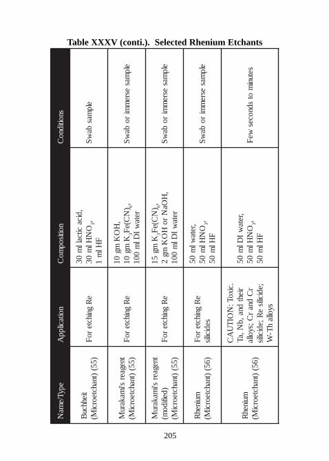
205
Table XXXV (conti.). Selected Rhenium Etchants
epyT/ema
Nnoitacilpp
Anoitisop
moC
snoitidnoC
tiehhcuB
)55()tnahcteorci
M(e
Rgnihcte
roF
,dicacitcall
m03
ON
Hlm
033,
FHl
m1
elpmas
baw
S
tnegaers'i
makaruM
)55()tnahcteorci
M(e
Rgnihcte
roF
,H
OK
mg01
Kmg
013
)N
C(eF
6,reta
wI
Dlm
001elp
masesre
mmi
roba
wS
tnegaers'i
makaruM
)deifidom(
)55()tnahcteorci
M(e
Rgnihcte
roF
Kmg
513
)N
C(eF
6,,
HOa
Nro
HO
Kmg
2reta
wI
Dlm
001elp
masesre
mmi
roba
wS
muinehR
)65()tnahcteorci
M(e
Rgnihcte
roF
sedicilis
,retawl
m05
ON
Hlm
053,
FHl
m05
elpmas
esrem
miro
baw
S
muinehR
)65()tnahcteorci
M(
.cixoT:N
OIT
UA
Crieht
dna,bN,aT
rC
dnar
C;syolla;edicilis
eR;edicilis
syollah
T-W
,retaw
IDl
m05
ON
Hlm
053,
FHl
m05
setunim
otsdnoces
weF
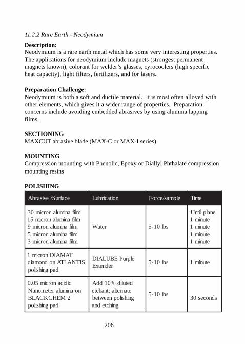
206
11.2.2 Rare Earth - Neodymium
Description:Neodymium is a rare earth metal which has some very interesting properties.The applications for neodymium include magnets (strongest permanentmagnets known), colorant for welder’s glasses, cyrocoolers (high specificheat capacity), light filters, fertilizers, and for lasers.
Preparation Challenge:Neodymium is both a soft and ductile material. It is most often alloyed withother elements, which gives it a wider range of properties. Preparationconcerns include avoiding embedded abrasives by using alumina lappingfilms.
SECTIONINGMAXCUT abrasive blade (MAX-C or MAX-I series)
MOUNTINGCompression mounting with Phenolic, Epoxy or Diallyl Phthalate compressionmounting resins
POLISHING
ecafruS/evisarbA noitacirbuL elpmas/ecroF emiT
mlifanimulanorcim03mlifanimulanorcim51
mlifanimulanorcim9mlifanimulanorcim5mlifanimulanorcim3
retaW sbl01-5
enalplitnUetunim1etunim1etunim1etunim1
TAMAIDnorcim1SITNALTAnodnomaid
dapgnihsilop
elpruPEBULAIDrednetxE
sbl01-5 etunim1
cidicanorcim50.0noanimularetemonaN
2MEHCKCALBdapgnihsilop
detulid%01ddAetanretla;tnahctegnihsilopneewteb
gnihctedna
sbl01-5sdnoces03
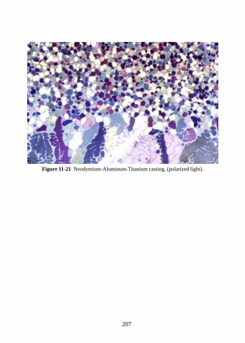
207
Figure 11-21 Neodymium-Aluminum-Titanium casting, (polarized light).
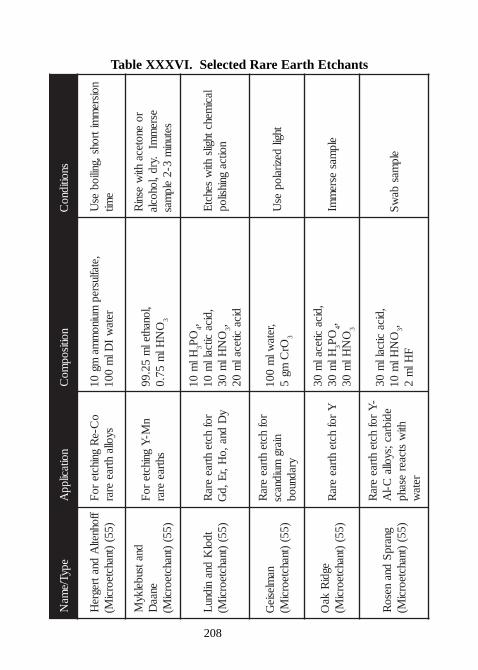
208
Table XXXVI. Selected Rare Earth EtchantsepyT/e
maN
noitacilppA
noitisopmo
Csnoitidno
C
ffohnetlA
dnatregreH
)55()tnahcteorci
M(o
C-eR
gnihctero
Fsyolla
htraeerar
,etaflusrepmuino
mma
mg01
r etaw
IDl
m001
noisrem
mitrohs,gniliobes
Ue
mit
dnatsubelkyM
enaaD
)55()tnahcteorci
M(
nM-
Ygnihcte
roF
shtraeerar
,l onahtelm
52.99O
NHl
m57.0
3
roenoteca
htiw
esniR
esrem
mI.yrd,lohocla
setunim
3-2elp
mas
tdolK
dnanidnu
L)55(
)tnahcteorciM(
rofhcte
htraeera
Ry
Ddna,o
H,rE,d
G
Hlm
013
OP
4,,dica
citcallm
01O
NHl
m03
3,dica
citecalm
02
lacimehcthgils
htiw
sehctE
noitcagnihsilop
namlesie
G)55(
)tnahcteorciM(
rofhcte
htraeera
Rniar g
muidnacsyradnuob
,retawl
m001
OrC
mg5
3
thgildeziralop
esU
egdiR
kaO
)55()tnahcteorci
M(Y
rofhcte
htraeera
R,dica
citecalm
03Hl
m03
3O
P4,
ON
Hlm
033
elpmas
esrem
mI
gnarpS
dnaneso
R)55(
)tnahcteorciM(
-Y
rofhcte
htraeera
Redibrac;syolla
C-lA
htiw
stcaeresahpreta
w
,dicacitcall
m03
ON
Hlm
013,
FHl
m2
elpmas
baw
S
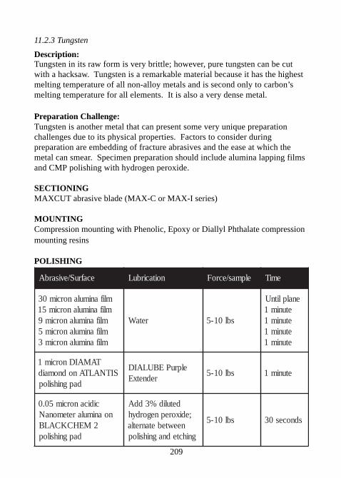
209
11.2.3 Tungsten
Description:Tungsten in its raw form is very brittle; however, pure tungsten can be cutwith a hacksaw. Tungsten is a remarkable material because it has the highestmelting temperature of all non-alloy metals and is second only to carbon’smelting temperature for all elements. It is also a very dense metal.
Preparation Challenge:Tungsten is another metal that can present some very unique preparationchallenges due to its physical properties. Factors to consider duringpreparation are embedding of fracture abrasives and the ease at which themetal can smear. Specimen preparation should include alumina lapping filmsand CMP polishing with hydrogen peroxide.
SECTIONINGMAXCUT abrasive blade (MAX-C or MAX-I series)
MOUNTINGCompression mounting with Phenolic, Epoxy or Diallyl Phthalate compressionmounting resins
POLISHING
ecafruS/evisarbA noitacirbuL elpmas/ecroF emiT
mlifanimulanorcim03mlifanimulanorcim51
mlifanimulanorcim9mlifanimulanorcim5mlifanimulanorcim3
retaW sbl01-5
enalplitnUetunim1etunim1etunim1etunim1
TAMAIDnorcim1SITNALTAnodnomaid
dapgnihsilop
elpruPEBULAIDrednetxE
sbl01-5 etunim1
cidicanorcim50.0noanimularetemonaN
2MEHCKCALBdapgnihsilop
detulid%3ddA;edixorepnegordyh
neewtebetanretlagnihctednagnihsilop
sbl01-5 sdnoces03
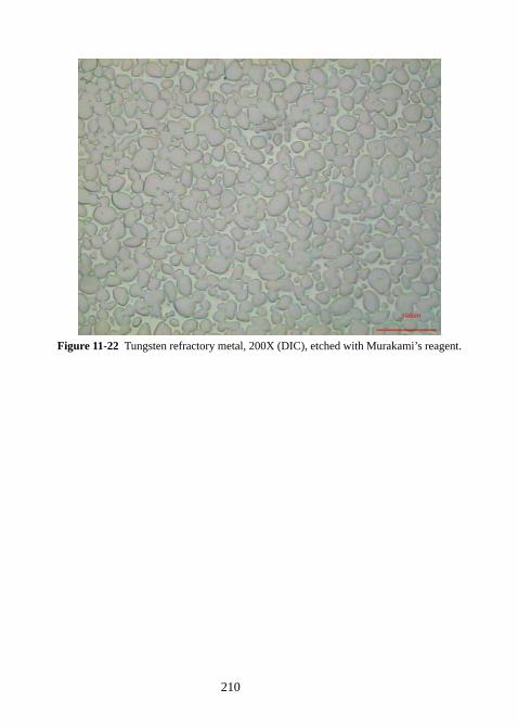
210
Figure 11-22 Tungsten refractory metal, 200X (DIC), etched with Murakami’s reagent.
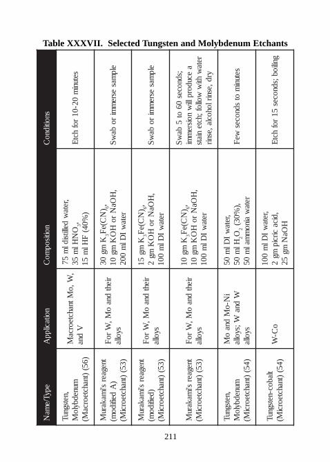
211
Table XXXVII. Selected Tungsten and Molybdenum EtchantsepyT/e
maN
noitacilppA
noitisopmo
Csnoitidno
C
,netsgnuTmunedbylo
M)65(
)tnahcteorcaM(
,W,o
MtnahcteorcaM
Vdna
,retaw
dellitsidlm
57O
NHl
m53
3,)
%04(F
Hlm
51setuni
m02-01
rofhct
E
tnegaers'i
makaruM
)A
deifidom(
)35()tnahcteorci
M(
riehtdna
oM,
Wro
Fsyolla
Kmg
033
)N
C(eF
6,,
HOa
Nro
HO
Kmg
01reta
wI
Dlm
002elp
masesre
mmi
roba
wS
tnegaers'i
makaruM
)deifidom(
)35()tnahcteorci
M(
riehtdna
oM,
Wro
Fsyolla
Kmg
513
)N
C(eF
6,,
HOa
Nro
HO
Kmg
2reta
wI
Dlm
001elp
masesre
mmi
roba
wS
tnegaers'i
makaruM
)35()tnahcteorci
M(rieht
dnao
M,W
roF
syolla
Kmg
013
)N
C(eF
6,,
HOa
Nro
HO
Kmg
01reta
wI
Dlm
001
;sdnoces06
ot5
baw
Sa
ecudorplliw
noisrem
mireta
whti
wwollof;hcte
niatsyrd,esnirlohocla,esnir
,netsgnuTmunedbylo
M)45(
)tnahcteorciM(
iN-o
Mdna
oM
Wdna
W;syollasyolla
,retaw
IDl
m05
Hlm
052O
2,)
%03(reta
waino
mmal
m05
setunim
otsdnoces
weF
tlaboc-netsgnuT)45(
)tnahcteorciM(
oC-
W,reta
wI
Dlm
001,dica
circipmg
2H
OaN
mg52
gniliob;sdnoces51
rofhct
E
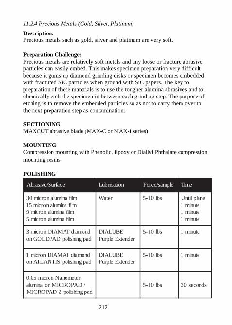
212
11.2.4 Precious Metals (Gold, Silver, Platinum)
Description:Precious metals such as gold, silver and platinum are very soft.
Preparation Challenge:Precious metals are relatively soft metals and any loose or fracture abrasiveparticles can easily embed. This makes specimen preparation very difficultbecause it gums up diamond grinding disks or specimen becomes embeddedwith fractured SiC particles when ground with SiC papers. The key topreparation of these materials is to use the tougher alumina abrasives and tochemically etch the specimen in between each grinding step. The purpose ofetching is to remove the embedded particles so as not to carry them over tothe next preparation step as contamination.
SECTIONINGMAXCUT abrasive blade (MAX-C or MAX-I series)
MOUNTINGCompression mounting with Phenolic, Epoxy or Diallyl Phthalate compressionmounting resins
POLISHING
ecafruS/evisarbA noitacirbuL elpmas/ecroF emiT
mlifanimulanorcim03mlifanimulanorcim51
mlifanimulanorcim9mlifanimulanorcim5
retaW sbl01-5 enalplitnUetunim1etunim1etunim1
dnomaidTAMAIDnorcim3dapgnihsilopDAPDLOGno
EBULAIDrednetxEelpruP
sbl01-5 etunim1
dnomaidTAMAIDnorcim1dapgnihsilopSITNALTAno
EBULAIDrednetxEelpruP
sbl01-5 etunim1
retemonaNnorcim50.0/DAPORCIMnoanimula
dapgnihsilop2DAPORCIMsbl01-5 sdnoces03
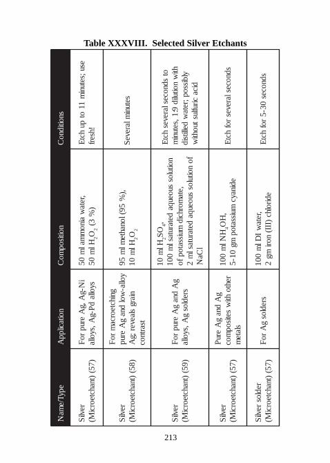
213
Table XXXVIII. Selected Silver Etchants
epyT/ema
Nnoitacilpp
Anoitisop
moC
snoitidnoC
revliS
)75()tnahcteorci
M(i
N-gA,g
Aerup
roF
syollad
P-gA,syolla
,retaw
ainom
malm
05Hl
m05
2O2
)%
3(esu;setuni
m11
otpu
hctE
!hserf
revliS
)85()tnahcteorci
M(
gnihcteorcam
roF
yolla-wol
dnag
Aerup
niargslaever; g
Atsartnoc
,)%
59(lonahteml
m59
Hlm
012O
2
setunimlareve
S
revliS
)95()tnahcteorci
M(g
Adna
gA
erupro
Fsredlos
gA,syolla
Hlm
012
OS
4,noitulos
suoeuqadetarutasl
m001
,etamorhcid
muissatopfofo
noitulossuoeuqa
detarutaslm
2l
CaN
otsdnoceslareves
hctE
htiw
noitulid9:1,setuni
mylbissop;reta
wdellitsid
dicaciruflustuohti
w
revliS
)75()tnahcteorci
M(
gA
dnag
Aeru
Prehto
htiw
setisopmoc
slatem
HNl
m001
4,
HO
edinaycmuissatop
mg01-5
sdnoceslarevesrof
hctE
redlosrevli
S)75(
)tnahcteorciM(
sredlosg
Aro
F,reta
wI
Dlm
001edirolhc
)III(nori
mg2
sdnoces03-5
rofhct
E
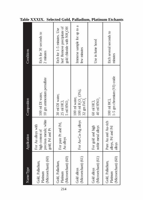
214
Table XXXIX. Selected Gold, Palladium, Platinum Etchants
epyT/ema
Nnoitacilpp
Anoitisop
moC
snoitidnoC
,muidallaP,dlo
GmunitalP
)06()tnahcteorci
M(
htiw
syollau
AroF
fotnetnochgih
etihw;slate
msuoicerp
tPdna
dP;dlog
,retaw
IDl
m001
etaflusrepmuino
mma
mg01
otsdnoces
03rof
hctEsetuni
m2
,muidallaP,dlo
GmunitalP
)06()tn ahcteorci
M(
,dPdnatP
eruproF
syollau
A
,retaw
IDl
m03
,lC
Hlm
52O
NHl
m5
3
esU.setuni
m5-1
rofhctE
foetatipicerp
evome
R!toh
HN
htiw
edirolhcdlog
4H
O
syolladlo
G)16(
)tnahcteorciM(
syollag
A-uC-u
AroF
,retawl
m001
Hlm
0012O
2,)
%3(l
CeFmg
233
aot
purof
elpmas
esrem
mIsetuni
mwef
syolladlo
G)16(
)tnahcteorciM(
hgihdna
dlogroF
syollalatem
elbon,l
CHl
m06
ON
Hlm
043
doohe
mufni
esU
,muidallaP,dlo
GmunitalP
)06()tnahcteorci
M(
hcir-uA
dnau
AeruP
dPdna
dP,syollasyolla
,lC
Hlm
001ed ixo
)IV(
muimorhc
mg5-1
otsdnoceslareves
hctEsetuni
m
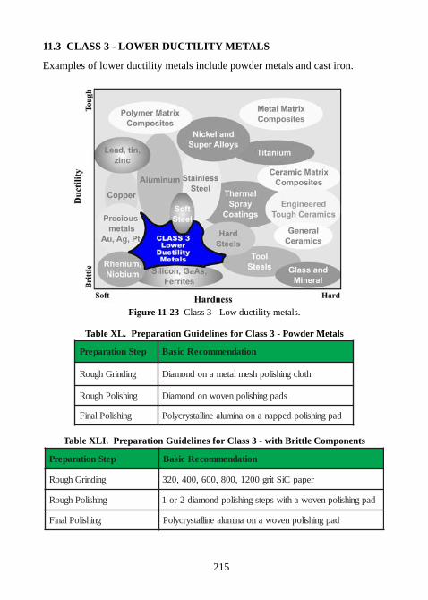
215
11.3 CLASS 3 - LOWER DUCTILITY METALS
Examples of lower ductility metals include powder metals and cast iron.
Figure 11-23 Class 3 - Low ductility metals.
Table XL. Preparation Guidelines for Class 3 - Powder Metals
petSnoitaraperP noitadnemmoceRcisaB
gnidnirGhguoR htolcgnihsilophsemlatemanodnomaiD
gnihsiloPhguoR sdapgnihsilopnevownodnomaiD
gnihsiloPlaniF dapgnihsilopdeppananoanimulaenillatsyrcyloP
Table XLI. Preparation Guidelines for Class 3 - with Brittle Components
petSnoitaraperP noitadnemmoceRcisaB
gnidnirGhguoR repapCiStirg0021,008,006,004,023
gnihsiloPhguoR dapgnihsilopnevowahtiwspetsgnihsilopdnomaid2ro1
gnihsiloPlaniF dapgnihsilopnevowanoanimulaenillatsyrcyloP
216
11.3.1 Sintered Iron - Powder Metallurgy
Description:Powder metallurgy is a very useful manufacturing process for parts designedwith hard-to-machine geometries. The process includes pressing a metalpowder into the rough shape and then sintering it just below the meltingtemperature of the alloy.
Preparation Challenge:The metallographic specimen preparation of powder metallurgy samples isaffected by the specimen’s composition, packing and sintering conditions.Microstructural features of interest include: porosity, grain size, inclusionsand orientation of voids. Proper metallurgical preparation takes into accountthat the microstructure may be porous and perhaps somewhat brittle due toinadequate sintering conditions.
Vacuum impregnation is often used to support voids and porosity beforeinitial grinding. In addition, metal smeared into pores can be removed by anintermediate etch in between polishing steps.
SECTIONINGMAXCUT abrasive blade (MAX-C or MAX-I series)
MOUNTINGCastable epoxy or acrylics with vacuum impregnation
ETCHANTSee recommendations for specific alloys.
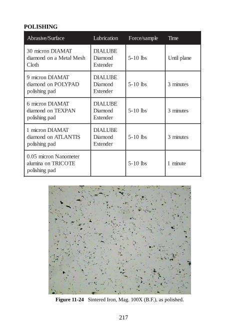
217
POLISHING
ecafruS/evisarbA noitacirbuL elpmas/ecroF emiT
TAMAIDnorcim03hseMlateManodnomaid
htolC
EBULAIDdnomaiDrednetxE
sbl01-5 enalplitnU
TAMAIDnorcim9DAPYLOPnodnomaid
dapgnihsilop
EBULAIDdnomaiDrednetxE
sbl01-5 setunim3
TAMAIDnorcim6NAPXETnodnomaid
dapgnihsilop
EBULAIDdnomaiDrednetxE
sbl01-5 setunim3
TAMAIDnorcim1SITNALTAnodnomaid
dapgnihsilop
EBULAIDdnomaiDrednetxE
sbl01-5 setunim3
retemonaNnorcim50.0ETOCIRTnoanimula
dapgnihsilopsbl01-5 etunim1
Figure 11-24 Sintered Iron, Mag. 100X (B.F.), as polished.
218
11.3.2 Cast Irons
Description:Cast irons are used for many applications. The reliabiity of cast iron dependson the microstructure of the graphite in the material. If the graphite formsflakes, then the cast iron will be brittle, becoming more so over time. Castiron with the addition of either magnesium or cerium, results in the graphiteforming nodules. Nodular cast iron has much better ductility than gray castiron (see figures 11-25a and 11-25b).
Preparation Challenge:Cast Irons are difficult materials to prepare properly because the graphitenodules or the graphite flakes are easily fractured and pulled out duringpreparation. By minimizing the sectioning damage and starting with a modestgrit size SiC paper, retaining these difficult particles can be accomplished.
SECTIONINGMAXCUT abrasive blade (MAX-D or MAX-I series)
MOUNTINGCompression mounting with Phenolic, Epoxy or Diallyl Phthalate compressionmounting resins
POLISHING
ecafruS/evisarbA noitacirbuL elpmas/ecroF emiT
repapCiStirg023repapCiStirg004repapCiStirg006repapCiStirg008repapCiStirg0021
retaW sbl01-5
enalplitnUetunim1etunim1etunim1etunim1
TAMAIDnorcim1DAPDLOGnodnomaid
dapgnihsilop
EBULAIDelpruP
rednetxEsbl01-5 setunim2
retemonaNnorcim50.0ETOCIRTnoanimula
dapgnihsilopsbl01-5 sdnoces03
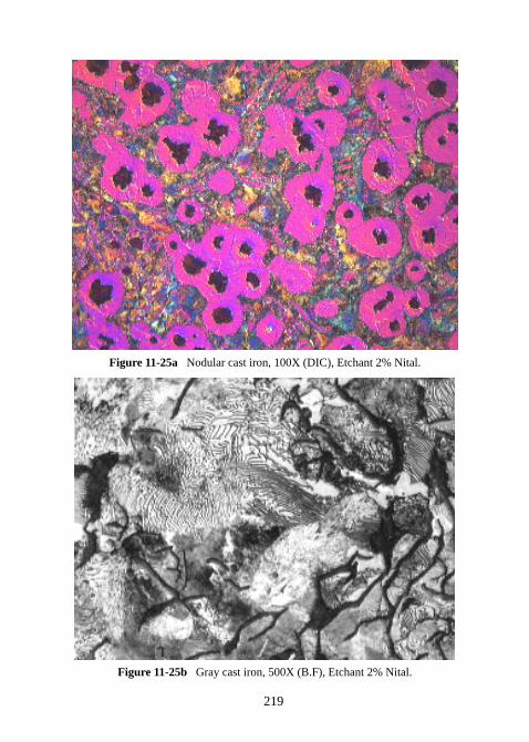
219
Figure 11-25a Nodular cast iron, 100X (DIC), Etchant 2% Nital.
Figure 11-25b Gray cast iron, 500X (B.F), Etchant 2% Nital.
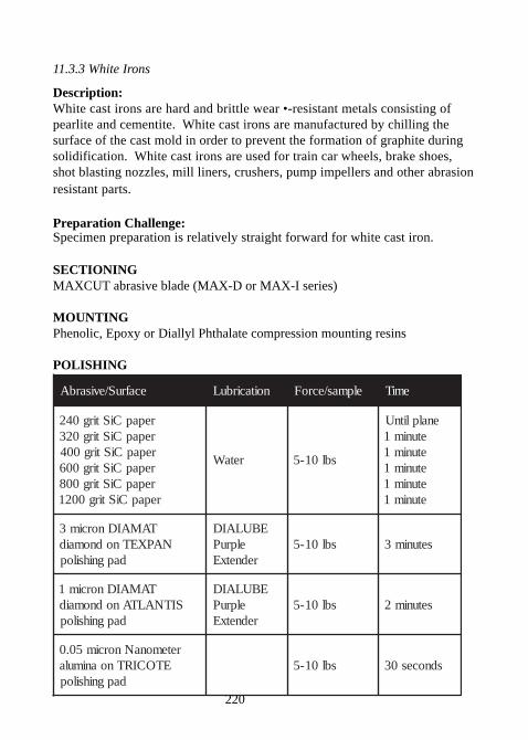
220
11.3.3 White Irons
Description:White cast irons are hard and brittle wear •-resistant metals consisting ofpearlite and cementite. White cast irons are manufactured by chilling thesurface of the cast mold in order to prevent the formation of graphite duringsolidification. White cast irons are used for train car wheels, brake shoes,shot blasting nozzles, mill liners, crushers, pump impellers and other abrasionresistant parts.
Preparation Challenge:Specimen preparation is relatively straight forward for white cast iron.
SECTIONINGMAXCUT abrasive blade (MAX-D or MAX-I series)
MOUNTINGPhenolic, Epoxy or Diallyl Phthalate compression mounting resins
POLISHING
ecafruS/evisarbA noitacirbuL elpmas/ecroF emiT
repapCiStirg042repapCiStirg023repapCiStirg004repapCiStirg006repapCiStirg008repapCiStirg0021
retaW sbl01-5
enalplitnUetunim1etunim1etunim1etunim1etunim1
TAMAIDnorcim3NAPXETnodnomaid
dapgnihsilop
EBULAIDelpruP
rednetxEsbl01-5 setunim3
TAMAIDnorcim1SITNALTAnodnomaid
dapgnihsilop
EBULAIDelpruP
rednetxEsbl01-5 setunim2
retemonaNnorcim50.0ETOCIRTnoanimula
dapgnihsilopsbl01-5 sdnoces03
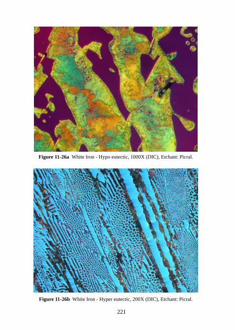
221
Figure 11-26a White Iron - Hypo eutectic, 1000X (DIC), Etchant: Picral.
Figure 11-26b White Iron - Hyper eutectic, 200X (DIC), Etchant: Picral.
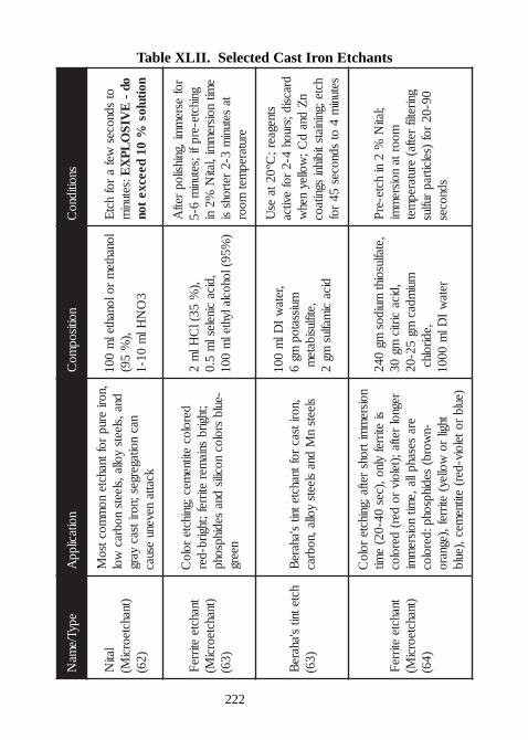
222
Table XLII. Selected Cast Iron EtchantsepyT/e
maN
noitacilppA
noitisopmo
Csnoitidno
C
latiN
)tnahcteorciM(
)26(
,norierup
roftnahcteno
mmoctso
Mdna,sleets
yolla,sleetsnobrac
wolnac
noitagerges;noritsacyarg
kcattanevenu
esuac
lonahtem
rolonahtelm
001,)
%59(
3O
NHl
m01-1
otsdnoces
wefa
rofhct
E:setuni
mod
-E
VISO
LPX
Enoitulos
%01
deecxeton
tnahcteetirre
F)tnahcteorci
M()36(
derolocetitne
mec;gnihcterolo
C;thgirb
sniamer
etirref;thgirb-der-eulb
srolocnocilis
dnasedihpsohp
neerg
,)%
53(lC
Hlm
2,dica
cineleslm
5.0)
%59(lohoclalyhtelm
001
rofesre
mmi,gnihsilop
retfA
gnihcte-erpfi;setunim
6-5e
mitnoisre
mmi,lati
N%2
nita
setunim
3-2retrohs
sierutarep
metmoor
hctetnits'ahare
B)36(
,noritsacroftnahctetnit
s'ahareB
sleetsn
Mdna
sleetsyolla,nobrac
,retaw
IDl
m001
muissatopmg
6,etiflusibate
mdica
cimaflus
mg2
stnegaer;C°02ta
esU
dracsid;sruoh4-2
rofevitca
nZ
dnad
C;wolley
nehw
hcte;gniniatstibihnisgnitaoc
setunim
4ot
sdnoces54
rof
tnahcteetirre
F)tnahcteorci
M()46(
noisrem
mitrohsretfa;gnihcte
roloC
sietirref
ylno,)ces04-02(
emit
regnolretfa;)teloiv
roder(
derolocera
sesahplla,emit
noisrem
mi-n
worb(sedihpsohp:deroloc
thgilro
wolley(etirref,)egnaro
)eulbroteloiv-der(
etitnemec,)eulb
,etaf lusoihtmuidos
mg042
,dicacirtic
mg03
muimdac
mg52-02
,edirolhcreta
wI
Dlm
0001
;latiN
%2
nihcte-er
Pmoorta
noisrem
migniretlif
retfa(erutarep
met09-02
rof)selcitrap
ruflussdnoces
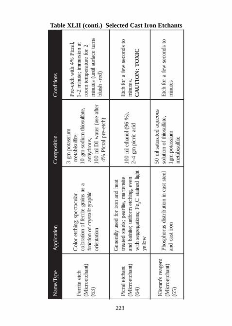
223
Table XLII (conti.) Selected Cast Iron Etchants
epyT/ema
Nnoitacilpp
Anoitisop
moC
snoitidnoC
hcteetirre
F)tnahcteorci
M()36(
ralucatceps;gnihcterolo
Ca
sasniarg
etirreffonoitaroloc
cihpargoll atsyrcfonoitcnuf
noitatneiro
muissatopmg
3,etiflusibate
m,etaflusoiht
muidosmg
01,suordyhna
retfaesu(
retaw
ID l
m001
)hcte-erplarciP
%4
,larciP
%4hti
whcte-er
Pta
noisrem
mi;etunim
2-12
roferutarep
metmoor
snrutecafruslitnu(
setunim
)der-hsiulb
tnahctelarciP
)tnahcteorciM(
)46(
taehdna
norirof
desuyllarene
Getisnetra
m,etilraep;sleetsdetaert
neve,gnihctemrofinu;etiniab
dnae
F;snoitagergeshti
w3
thgildeniats
Cwolley
,)%
69(lonahtelm
001dica
circipmg
4-2
otsdnoces
wefa
rofhct
E.setuni
mCI
XO
T:
NOI
TU
AC
tnegaers'
mmel
K)tnahcteorci
M()56(
leetstsacni
noitubirtsidsurohpsoh
Pnoritsac
dna
suoeuqadetarutasl
m05
,etaflusoihtfonoitulos
muissatopmg1
etiflusibatem
otsdnoces
wefa
rofhct
Esetuni
m
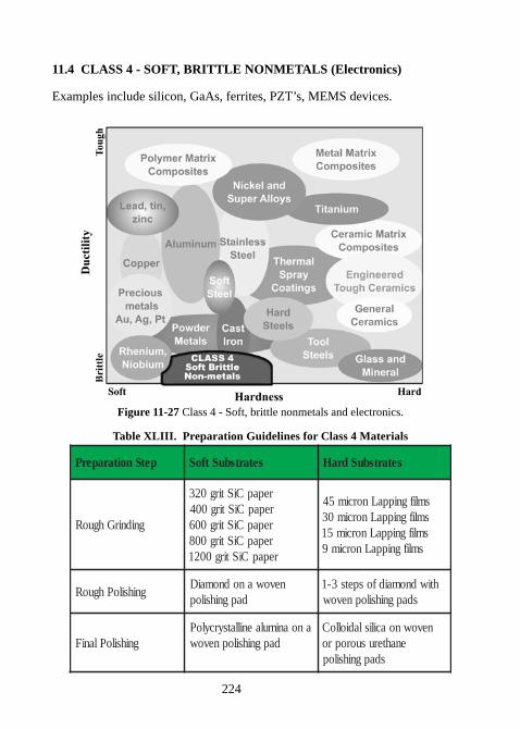
224
11.4 CLASS 4 - SOFT, BRITTLE NONMETALS (Electronics)
Examples include silicon, GaAs, ferrites, PZT’s, MEMS devices.
Figure 11-27 Class 4 - Soft, brittle nonmetals and electronics.
Table XLIII. Preparation Guidelines for Class 4 Materials
petSnoitaraperP setartsbuStfoS setartsbuSdraH
gnidnirGhguoR
repapCiStirg023repapCiStirg004repapCiStirg006repapCiStirg008repapCiStirg0021
smlifgnippaLnorcim54smlifgnippaLnorcim03smlifgnippaLnorcim51
smlifgnippaLnorcim9
gnihsiloPhguoRnevowanodnomaiD
dapgnihsilophtiwdnomaidfospets3-1
sdapgnihsilopnevow
gnihsiloPlaniFanoanimulaenillatsyrcyloP
dapgnihsilopnevownevownoacilisladiolloC
enahterusuoroprosdapgnihsilop
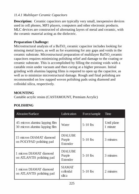
225
11.4.1 Multilayer Ceramic Capacitors
Description: Ceramic capacitors are typically very small, inexpensive devicesused in cell phones, MP3 players, computers and other electronic products.MLC devices are constructed of alternating layers of metal and ceramic, withthe ceramic material acting as the dielectric.
Preparation Challenge:Microstructural analysis of a BaTiO
3 ceramic capacitor includes looking for
missing metal layers, as well as for examining for any gaps and voids in theceramic substrate. Microstructural preparation of multilayer BaTiO
3 ceramic
capacitors requires minimizing polishing relief and damage to the coating orceramic substrate. This is accomplished by filling the existing voids with acastable resin under vacuum and then curing at a higher pressure. Initialgrinding with alumina lapping films is required to open up the capacitor, aswell as to minimize microstructural damage. Rough and final polishing arerecommended on low napped woven polishing pads using diamond andcolloidal silica, respectively.
MOUNTINGCastable acrylic resins (CASTAMOUNT, Premium Acrylic)
POLISHING
ecafruS/evisarbA noitacirbuL elpmas/ecroF emiT
mlifgnippalanimulanorcim54mlifgnippalanimulanorcim03
retaW sbl01-5enalplitnU
etunim1
dnomaidTAMAIDnorcim51dapgnihsilopDAPYLOPno
EBULAIDelpruP
rednetxEsbl01-5 setunim3
dnomaidTAMAIDnorcim1dapgnihsilopSITNALTAno
EBULAIDelpruP
rednetxEsbl01-5 setunim3
dnomaidTAMAIDnorcim1dapgnihsilopSITNALTAno
TAMAISladiolloc
acilissbl01-5 setunim2
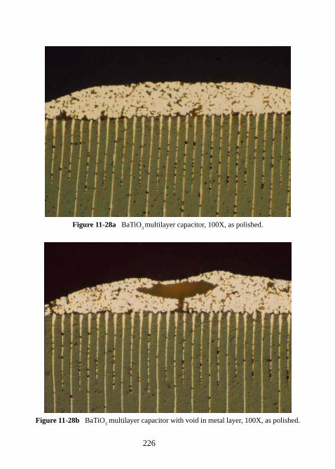
226
Figure 11-28a BaTiO3 multilayer capacitor, 100X, as polished.
Figure 11-28b BaTiO3 multilayer capacitor with void in metal layer, 100X, as polished.
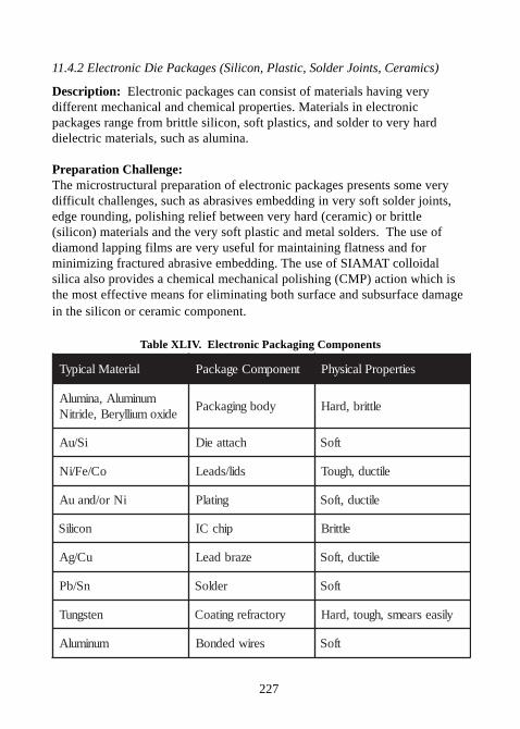
227
11.4.2 Electronic Die Packages (Silicon, Plastic, Solder Joints, Ceramics)
Description: Electronic packages can consist of materials having verydifferent mechanical and chemical properties. Materials in electronicpackages range from brittle silicon, soft plastics, and solder to very harddielectric materials, such as alumina.
Preparation Challenge:The microstructural preparation of electronic packages presents some verydifficult challenges, such as abrasives embedding in very soft solder joints,edge rounding, polishing relief between very hard (ceramic) or brittle(silicon) materials and the very soft plastic and metal solders. The use ofdiamond lapping films are very useful for maintaining flatness and forminimizing fractured abrasive embedding. The use of SIAMAT colloidalsilica also provides a chemical mechanical polishing (CMP) action which isthe most effective means for eliminating both surface and subsurface damagein the silicon or ceramic component.
Table XLIV. Electronic Packaging Components
lairetaMlacipyT tnenopmoCegakcaP seitreporPlacisyhP
munimulA,animulAedixomuillyreB,edirtiN
ydobgnigakcaP elttirb,draH
iS/uA hcattaeiD tfoS
oC/eF/iN sdil/sdaeL elitcud,hguoT
iNro/dnauA gnitalP elitcud,tfoS
nociliS pihcCI elttirB
uC/gA ezarbdaeL elitcud,tfoS
nS/bP redloS tfoS
netsgnuT yrotcarfergnitaoC ylisaesraems,hguot,draH
munimulA seriwdednoB tfoS
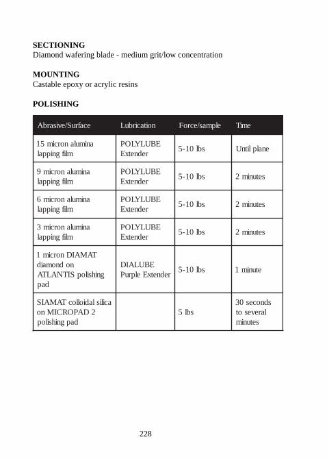
228
SECTIONINGDiamond wafering blade - medium grit/low concentration
MOUNTINGCastable epoxy or acrylic resins
POLISHING
ecafruS/evisarbA noitacirbuL elpmas/ecroF emiT
animulanorcim51mlifgnippal
EBULYLOPrednetxE
sbl01-5 enalplitnU
animulanorcim9mlifgnippal
EBULYLOPrednetxE
sbl01-5 setunim2
animulanorcim6mlifgnippal
EBULYLOPrednetxE
sbl01-5 setunim2
animulanorcim3mlifgnippal
EBULYLOPrednetxE
sbl01-5 setunim2
TAMAIDnorcim1nodnomaid
gnihsilopSITNALTAdap
EBULAIDrednetxEelpruP
sbl01-5 etunim1
acilisladiollocTAMAIS2DAPORCIMno
dapgnihsilopsbl5
sdnoces03larevesot
setunim
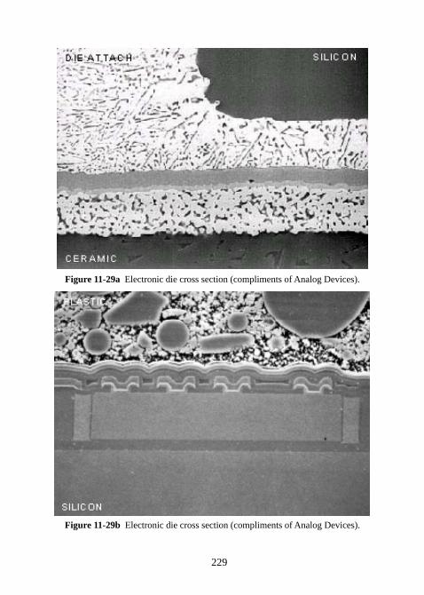
229
Figure 11-29a Electronic die cross section (compliments of Analog Devices).
Figure 11-29b Electronic die cross section (compliments of Analog Devices).
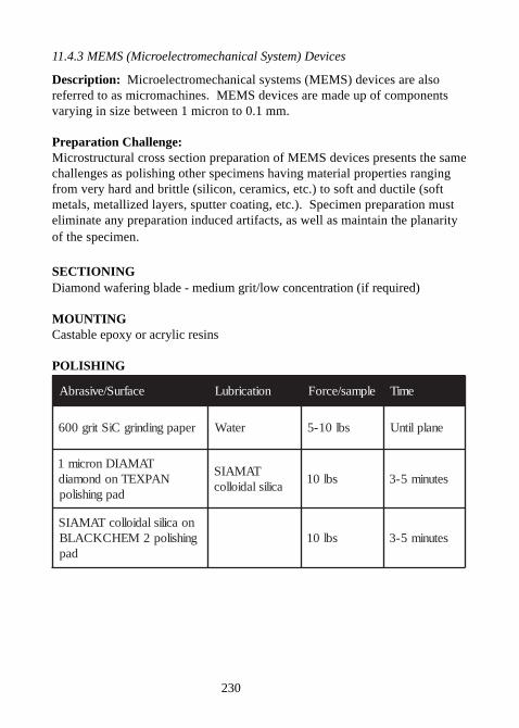
230
11.4.3 MEMS (Microelectromechanical System) Devices
Description: Microelectromechanical systems (MEMS) devices are alsoreferred to as micromachines. MEMS devices are made up of componentsvarying in size between 1 micron to 0.1 mm.
Preparation Challenge:Microstructural cross section preparation of MEMS devices presents the samechallenges as polishing other specimens having material properties rangingfrom very hard and brittle (silicon, ceramics, etc.) to soft and ductile (softmetals, metallized layers, sputter coating, etc.). Specimen preparation musteliminate any preparation induced artifacts, as well as maintain the planarityof the specimen.
SECTIONINGDiamond wafering blade - medium grit/low concentration (if required)
MOUNTINGCastable epoxy or acrylic resins
POLISHING
ecafruS/evisarbA noitacirbuL elpmas/ecroF emiT
repapgnidnirgCiStirg006 retaW sbl01-5 enalplitnU
TAMAIDnorcim1NAPXETnodnomaid
dapgnihsilop
TAMAISacilisladiolloc
sbl01 setunim5-3
noacilisladiollocTAMAISgnihsilop2MEHCKCALB
dapsbl01 setunim5-3
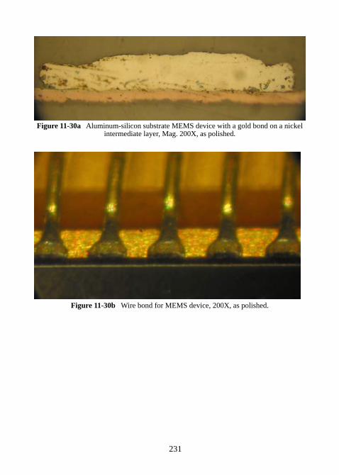
231
Figure 11-30a Aluminum-silicon substrate MEMS device with a gold bond on a nickelintermediate layer, Mag. 200X, as polished.
Figure 11-30b Wire bond for MEMS device, 200X, as polished.
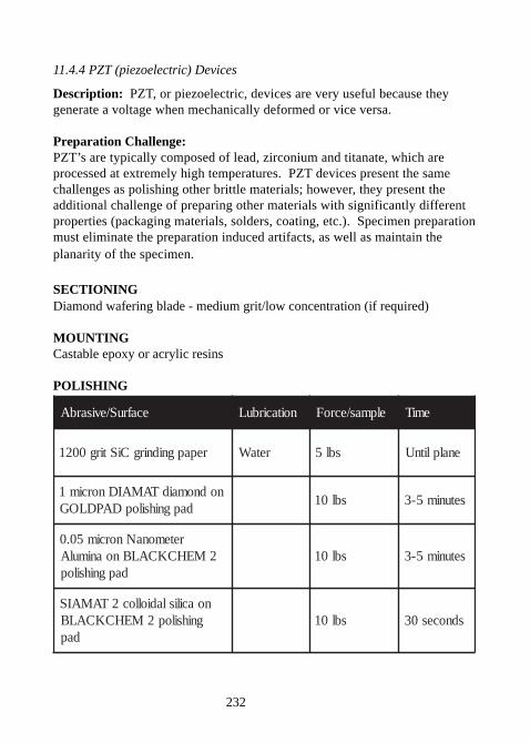
232
11.4.4 PZT (piezoelectric) Devices
Description: PZT, or piezoelectric, devices are very useful because theygenerate a voltage when mechanically deformed or vice versa.
Preparation Challenge:PZT’s are typically composed of lead, zirconium and titanate, which areprocessed at extremely high temperatures. PZT devices present the samechallenges as polishing other brittle materials; however, they present theadditional challenge of preparing other materials with significantly differentproperties (packaging materials, solders, coating, etc.). Specimen preparationmust eliminate the preparation induced artifacts, as well as maintain theplanarity of the specimen.
SECTIONINGDiamond wafering blade - medium grit/low concentration (if required)
MOUNTINGCastable epoxy or acrylic resins
POLISHING
ecafruS/evisarbA noitacirbuL elpmas/ecroF emiT
repapgnidnirgCiStirg0021 retaW sbl5 enalplitnU
nodnomaidTAMAIDnorcim1dapgnihsilopDAPDLOG
sbl01 setunim5-3
retemonaNnorcim50.02MEHCKCALBnoanimulA
dapgnihsilopsbl01 setunim5-3
noacilisladiolloc2TAMAISgnihsilop2MEHCKCALB
dapsbl01 sdnoces03
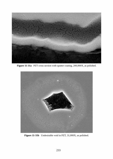
233
Figure 11-31a PZT cross section with sputter coating, 200,000X, as polished.
Figure 11-31b Undesirable void in PZT, 31,000X, as polished.
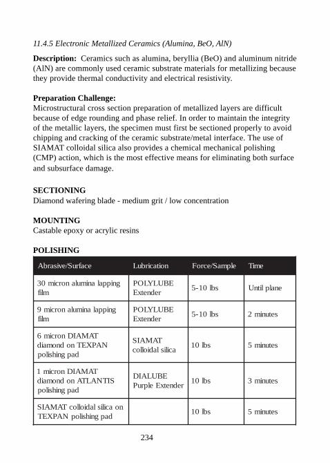
234
11.4.5 Electronic Metallized Ceramics (Alumina, BeO, AlN)
Description: Ceramics such as alumina, beryllia (BeO) and aluminum nitride(AlN) are commonly used ceramic substrate materials for metallizing becausethey provide thermal conductivity and electrical resistivity.
Preparation Challenge:Microstructural cross section preparation of metallized layers are difficultbecause of edge rounding and phase relief. In order to maintain the integrityof the metallic layers, the specimen must first be sectioned properly to avoidchipping and cracking of the ceramic substrate/metal interface. The use ofSIAMAT colloidal silica also provides a chemical mechanical polishing(CMP) action, which is the most effective means for eliminating both surfaceand subsurface damage.
SECTIONINGDiamond wafering blade - medium grit / low concentration
MOUNTINGCastable epoxy or acrylic resins
POLISHING
ecafruS/evisarbA noitacirbuL elpmaS/ecroF emiT
gnippalanimulanorcim03mlif
EBULYLOPrednetxE
sbl01-5 enalplitnU
gnippalanimulanorcim9mlif
EBULYLOPrednetxE
sbl01-5 setunim2
TAMAIDnorcim6NAPXETnodnomaid
dapgnihsilop
TAMAISacilisladiolloc
sbl01 setunim5
TAMAIDnorcim1SITNALTAnodnomaid
dapgnihsilop
EBULAIDrednetxEelpruP
sbl01 setunim3
noacilisladiollocTAMAISdapgnihsilopNAPXET
sbl01 setunim5
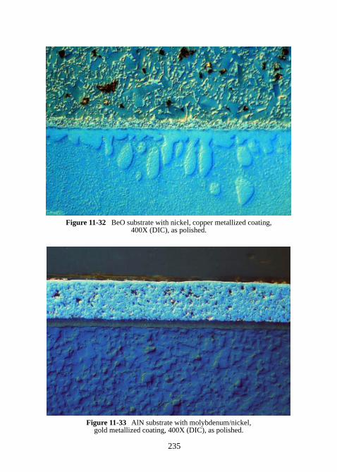
235
Figure 11-32 BeO substrate with nickel, copper metallized coating,400X (DIC), as polished.
Figure 11-33 AlN substrate with molybdenum/nickel,gold metallized coating, 400X (DIC), as polished.
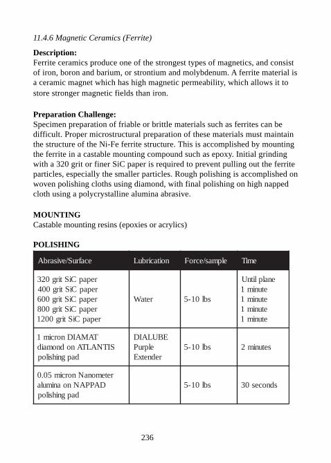
236
11.4.6 Magnetic Ceramics (Ferrite)
Description:Ferrite ceramics produce one of the strongest types of magnetics, and consistof iron, boron and barium, or strontium and molybdenum. A ferrite material isa ceramic magnet which has high magnetic permeability, which allows it tostore stronger magnetic fields than iron.
Preparation Challenge:Specimen preparation of friable or brittle materials such as ferrites can bedifficult. Proper microstructural preparation of these materials must maintainthe structure of the Ni-Fe ferrite structure. This is accomplished by mountingthe ferrite in a castable mounting compound such as epoxy. Initial grindingwith a 320 grit or finer SiC paper is required to prevent pulling out the ferriteparticles, especially the smaller particles. Rough polishing is accomplished onwoven polishing cloths using diamond, with final polishing on high nappedcloth using a polycrystalline alumina abrasive.
MOUNTINGCastable mounting resins (epoxies or acrylics)
POLISHING
ecafruS/evisarbA noitacirbuL elpmas/ecroF emiT
repapCiStirg023repapCiStirg004repapCiStirg006repapCiStirg008repapCiStirg0021
retaW sbl01-5
enalplitnUetunim1etunim1etunim1etunim1
TAMAIDnorcim1SITNALTAnodnomaid
dapgnihsilop
EBULAIDelpruP
rednetxEsbl01-5 setunim2
retemonaNnorcim50.0DAPPANnoanimula
dapgnihsilopsbl01-5 sdnoces03
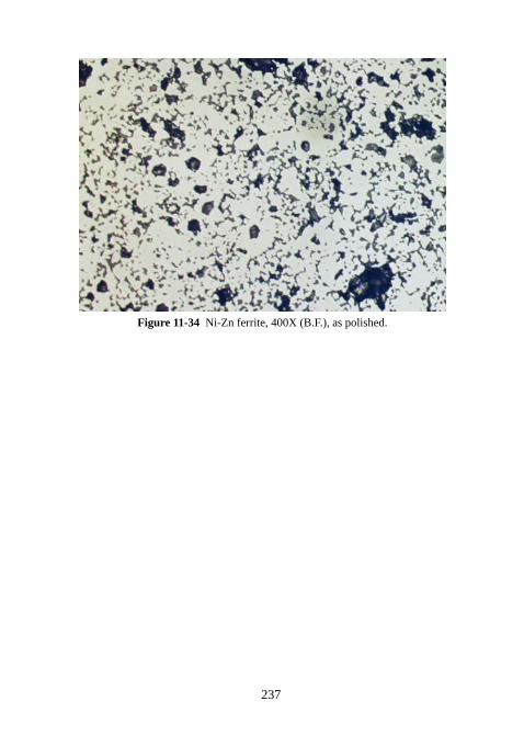
237
Figure 11-34 Ni-Zn ferrite, 400X (B.F.), as polished.
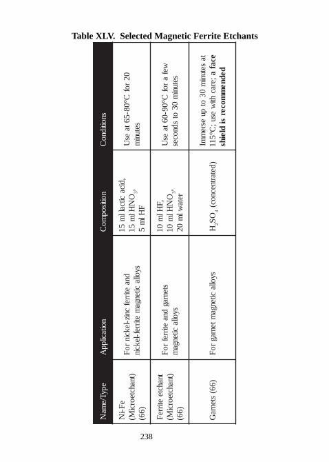
238
Table XLV. Selected Magnetic Ferrite Etchants
epyT/ema
Nnoitacilpp
Anoitisop
moC
snoitidnoC
eF-i
N)tnahcteorci
M()66(
dnaetirref
cniz-lekcinro
Fsyolla
citengam
etirref-lekcin
,dicacitcall
m51
ON
Hlm
513,
FHl
m5
02rof
C°08-56taes
Usetuni
m
tnahcteetirre
F)tnahcteorci
M()66(
stenragdna
etirrefro
Fsyolla
citengam
,FHl
m01
ON
Hlm
013, reta
wlm
02
wefa
rofC°09-06ta
esU
setunim
03ot
sdnoces
)66(stenra
Gsyolla
citengamtenrag
roF
H2
OS
4)detartnecnoc(
tasetuni
m03
otpu
esrem
mI;erac
htiw
esu;C°511
ecafa dedne
mmocer
sidleihs
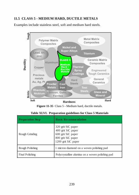
239
11.5 CLASS 5 - MEDIUM HARD, DUCTILE METALS
Examples include stainless steel, soft and medium hard steels.
Figure 11-35 Class 5 - Medium hard, ductile metals.
Table XLVI. Preparation guidelines for Class 5 Materials
petSnoitaraperP noitadnemmoceRcisaB
gnidnirGhguoR
repapCiStirg023repapCiStirg004repapCiStirg006repapCiStirg008repapCiStirg0021
gnihsiloPhguoR dapgnihsilopnevowanodnomaidnorcim1
gnihsiloPlaniF dapgnihsilopnevowanoanimulaenillatsyrcyloP
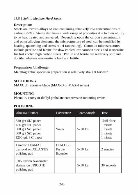
240
11.5.1 Soft to Medium Hard Steels
Description:Steels are ferrous alloys of iron containing relatively low concentrations ofcarbon (<2%). Steels also have a wide range of properties due to their abilityto be heat treated and annealed. Depending upon the carbon concentrationand other alloying elements, the microstructure of steel can be modified byheating, quenching and stress relief (annealing). Common microstructuresinclude pearlite and ferrite for slow cooled low carobon steels and martensitefor fast cooled high carbon steels. Perlite and ferrite are relatively soft andductile, whereas martensite is hard and brittle.
Preparation Challenge:Metallographic specimen preparation is relatively straight forward.
SECTIONINGMAXCUT abrasive blade (MAX-D or MAX-I series)
MOUNTINGPhenolic, epoxy or diallyl phthalate compression mounting resins
POLISHING
ecafruS/evisarbA noitacirbuL elpmas/ecroF emiT
repapCiStirg023repapCiStirg004repapCiStirg006repapCiStirg008repapCiStirg0021
retaW sbl01-5
enalplitnUetunim1etunim1etunim1etunim1
TAMAIDnorcim1SITNALTAnodnomaid
dapgnihsilop
EBULAIDelpruP
rednetxEsbl01-5 setunim2
retemonaNnorcim50.0ETOCIRTnoanimula
dapgnihsilopsbl01-5 sdnoces03
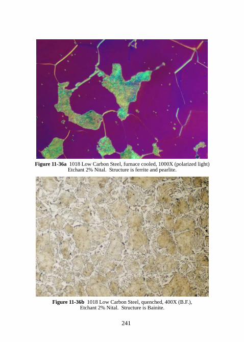
241
Figure 11-36a 1018 Low Carbon Steel, furnace cooled, 1000X (polarized light)Etchant 2% Nital. Structure is ferrite and pearlite.
Figure 11-36b 1018 Low Carbon Steel, quenched, 400X (B.F.),Etchant 2% Nital. Structure is Bainite.
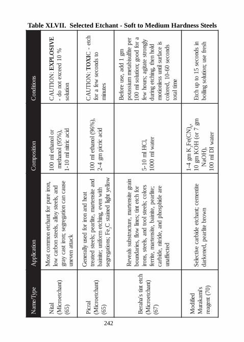
242
Table XLVII. Selected Etchant - Soft to Medium Hardness SteelsepyT/e
maN
noitacilppA
noitisopmo
Csnoitidno
C
latiN
)tnahcteorciM(
)56(
,norierup
roftnahcteno
mmoctso
Mdna,sleets
yolla,sleetsnobrac
wolesuac
nacnoitagerges;noritsac
yargkcatta
nevenu
rolonahtelm
001,)
%59(lonahtem
dicacirtinl
m01-1
:N
OITU
AC
EVIS
OLP
XE
%01
d eecxetonod
-noitulos
larciP)tnahcteorci
M()56(
taehdna
norirof
desuyllarene
Gdna
etisnetram,etilraep;sleets
detaerthti
wneve,gnihcte
mrofinu;etiniabeF;snoitagerges
3wolleythgil
deniatsC
,)%69(lonahtel
m001
dicacircip
mg4-2
:N
OITU
AC
IX
OT
hcte-
C otsdnoces
wefa
rofsetuni
m
hctetnits'ahare
B)tnahcteorci
M()76(
niargetisnetra
m,erutcurtsbusslaeve
Rrof
hctetnit;senilwolf,seiradnuob
sroloc;s leetslootdna,sleets,snori
;etilraep,etiniab,etisnetram,etirref
eraedihpsohp
dna,edirtin,edibracdetceffanu
,lC
Hlm
01-5reta
wlm
0001
mg1
dda,esuerofe
Brep
etiflusibatem
muissatopa
rofdoog;noitulosl
m001
ylgnortsetatiga; sruoh
wefdloh
neht,gnihctegnirud
siecafruslitnu
sselnoitom
sdnoces06-01,deroloc
emitlatot
deifidoM
s'imakaru
M)07(tnegaer
etitnemec;tnahcte
edibracevitceleS
nworb
etilraep,denekrad
Kmg
4-13
)N
C(eF6,
mg7
ro(H
OK
mg01
,)H
OaN
retaw
IDl
m001
nisdnoces
51ot
puhctE
hserfesu;noitulos
gniliob
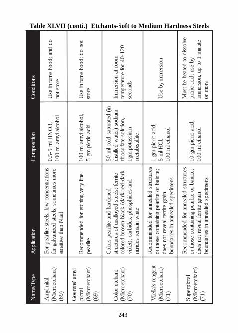
243
Table XLVII (conti.) Etchants-Soft to Medium Hardness SteelsepyT/ e
maN
noit acil ppA
noitisopmo
Csnoiti dno
C
l ati nl ym
A)t nahct eorci
M() 96(
snoit art necnocwol , sl eets
etilraepr o
Fer o
mse
mit emos ;sl eets
dezi navl agr of
l atiN
nahtevitisnes
, 3O
NHl
m5- 5. 0
l ohocl al ymal
m001
oddna; dooh
emuf
nies
Uer ots t on
l yma' snereo
Gl arci p
)t nahct eorciM(
) 96(
enifyrev
gni hct er of
dednem
moceR
etilraep,l ohocl al y
malm
001di ca
circi pmg
5t on
od; doohe
mufni
esU
er ots
t nahct er ol o
C)t nahct eorci
M() 07(
denedrahdna
etilraepsr ol o
Cetirref ;sl eets
deyoll anuf oserut curts
krad- derkrad(
kcal b-nwor b
der ol ocdna
sedi hpsohp, sedi brac ;)t el oi veti h
wni a
mersedirti n
ni(det arut as- dl ocl
m05
mui dos)ret a
wdellitsi d
, noit ul oset afl usoi ht
nruissat opmg1
etifl usi bat em
moor t anoisre
mmI
021- 04r of
erut arepmet
sdnoces
tnegaers' all eli
V)t nahct eorci
M() 17(
serut curtsdel aenna
r ofdedne
mmoce
R; eti ni ab
r oetilraep
gni ni at nocesoht
r oni arg
etirref l aever t onseod
snemi ceps
del aennani
seiradnuob
, di cacirci p
mg1
,lC
Hlm
5l onaht el
m001
noisrem
miyb
esU
l arci prepuS
)t nahct eorciM(
) 17(
serut curtsdel aenna
r ofdedne
mmoce
R; eti ni ab
r oetilraep
gni ni at nocesoht
r oni arg
etirref l aever t onseod
snemi ceps
del aennani
seiradnuob
, di cacirci p
mg01
l onaht elm
001
evl ossi dot
det aehebtsu
Myb
es u; di cacirci p
et unim
1ot
pu, noisrem
mier o
mr o
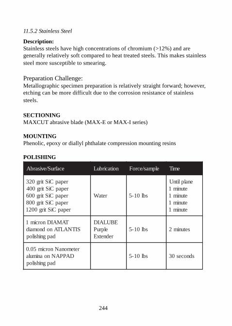
244
11.5.2 Stainless Steel
Description:Stainless steels have high concentrations of chromium (>12%) and aregenerally relatively soft compared to heat treated steels. This makes stainlesssteel more susceptible to smearing.
Preparation Challenge:Metallographic specimen preparation is relatively straight forward; however,etching can be more difficult due to the corrosion resistance of stainlesssteels.
SECTIONINGMAXCUT abrasive blade (MAX-E or MAX-I series)
MOUNTINGPhenolic, epoxy or diallyl phthalate compression mounting resins
POLISHING
ecafruS/evisarbA noitacirbuL elpmas/ecroF emiT
repapCiStirg023repapCiStirg004repapCiStirg006repapCiStirg008repapCiStirg0021
retaW sbl01-5
enalplitnUetunim1etunim1etunim1etunim1
TAMAIDnorcim1SITNALTAnodnomaid
dapgnihsilop
EBULAIDelpruP
rednetxEsbl01-5 setunim2
retemonaNnorcim50.0DAPPANnoanimula
dapgnihsilopsbl01-5 sdnoces03
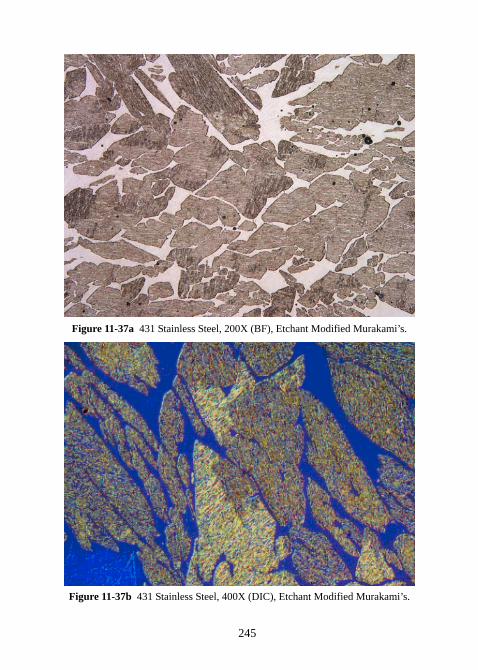
245
Figure 11-37a 431 Stainless Steel, 200X (BF), Etchant Modified Murakami’s.
Figure 11-37b 431 Stainless Steel, 400X (DIC), Etchant Modified Murakami’s.
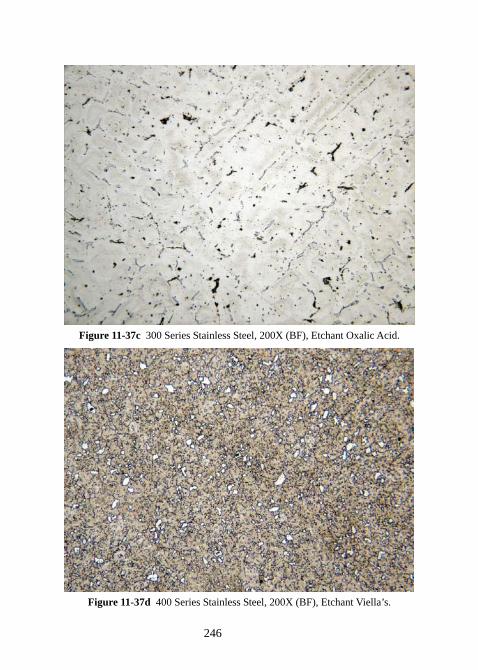
246
Figure 11-37c 300 Series Stainless Steel, 200X (BF), Etchant Oxalic Acid.
Figure 11-37d 400 Series Stainless Steel, 200X (BF), Etchant Viella’s.
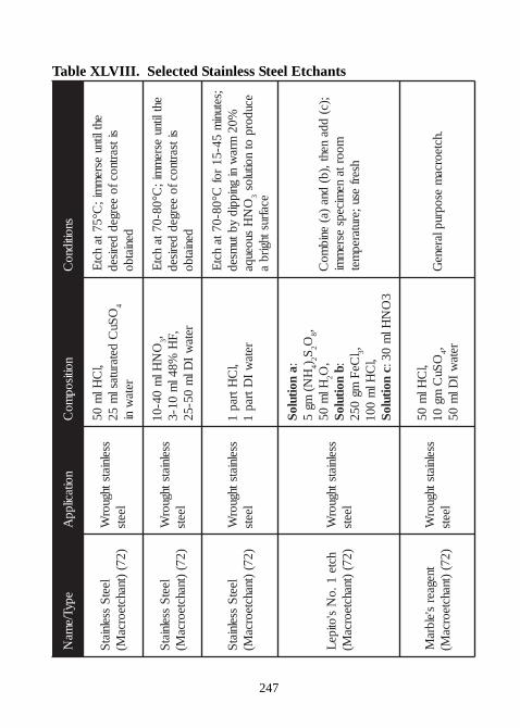
247
Table XLVIII. Selected Stainless Steel EtchantsepyT/e
maN
noitacilppA
noitisopmo
Csnoitidno
C
leetS
sselniatS
)27()tnahcteorca
M(sselniatsthguor
Wleets
,lC
Hlm
05O
SuC
detarutaslm
524
retaw
ni
ehtlitnuesre
mmi;
C°57tahct
Esitsartnocfo
eergedderiseddeniatbo
leetS
sselniatS
)27()tnahcteorca
M(sse lniatsthguor
Wleets
ON
Hlm
04-013,
,FH
%84lm
01-3reta
wI
Dlm
05-52
ehtlitnuesre
mmi;
C°08-07tahct
Esitsartnocfo
eergedderiseddeniatbo
leetS
sselnia tS
)27()tnahcteorca
M(sselniatsthguor
Wleets
,lC
Htrap1
retaw
IDtrap
1
;setunim
54-51rof
C°08-07tahct
E%02
mraw
nignippid
ybtumsed
ON
Hsuoeuqa
3ecudorp
otnoitulos
ecafrusthgirba
hcte1.o
Ns'otipe
L)27(
)tnahcteorcaM(
sselniatsthguorW
leets
anoituloS
:H
N(mg
54)
2S2O
8,Hl
m05
2,
O bnoituloS
:l
CeF
mg052
3,,l
CHl
m001
cnoituloS
3O
NHl
m03:
;)c(dda
neht,)b(dna
)a(enib
moC
moortane
micepsesre
mmi
hserfesu;erutarep
met
tneg aers'elbra
M)27(
)tnahcteorcaM(
sselniatsthguorW
leets
,lC
Hlm
05O
SuC
mg01
4, retaw
IDl
m05
.hcteorcam
esopruplareneG
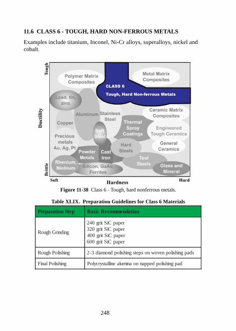
248
11.6 CLASS 6 - TOUGH, HARD NON-FERROUS METALS
Examples include titanium, Inconel, Ni-Cr alloys, superalloys, nickel andcobalt.
Figure 11-38 Class 6 - Tough, hard nonferrous metals.
Table XLIX. Preparation Guidelines for Class 6 Materials
petSnoitaraperP noitadnemmoceRcisaB
gnidnirGhguoR
repapCiStirg042repapCiStirg023repapCiStirg004repapCiStirg006
gnihsiloPhguoR sdapgnihsilopnevownospetsgnihsilopdnomaid3-2
gnihsiloPlaniF dapgnihsilopdeppannoanimulaenillatsyrcyloP
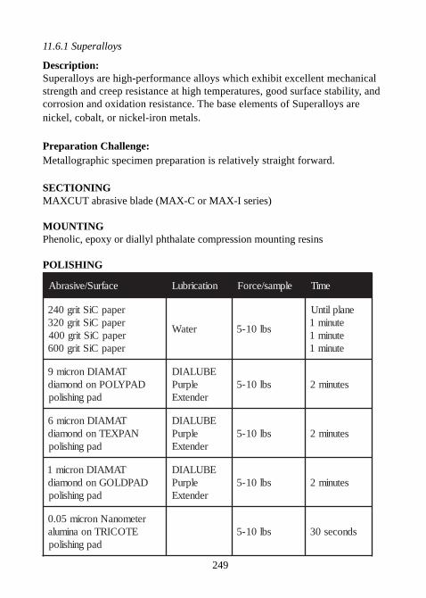
249
11.6.1 Superalloys
Description:Superalloys are high-performance alloys which exhibit excellent mechanicalstrength and creep resistance at high temperatures, good surface stability, andcorrosion and oxidation resistance. The base elements of Superalloys arenickel, cobalt, or nickel-iron metals.
Preparation Challenge:Metallographic specimen preparation is relatively straight forward.
SECTIONINGMAXCUT abrasive blade (MAX-C or MAX-I series)
MOUNTINGPhenolic, epoxy or diallyl phthalate compression mounting resins
POLISHING
ecafruS/evisarbA noitacirbuL elpmas/ecroF emiT
repapCiStirg042repapCiStirg023repapCiStirg004repapCiStirg006
retaW sbl01-5
enalplitnUetunim1etunim1etunim1
TAMAIDnorcim9DAPYLOPnodnomaid
dapgnihsilop
EBULAIDelpruP
rednetxEsbl01-5 setunim2
TAMAIDnorcim6NAPXETnodnomaid
dapgnihsilop
EBULAIDelpruP
rednetxEsbl01-5 setunim2
TAMAIDnorcim1DAPDLOGnodnomaid
dapgnihsilop
EBULAIDelpruP
rednetxEsbl01-5 setunim2
retemonaNnorcim50.0ETOCIRTnoanimula
dapgnihsilopsbl01-5 sdnoces03
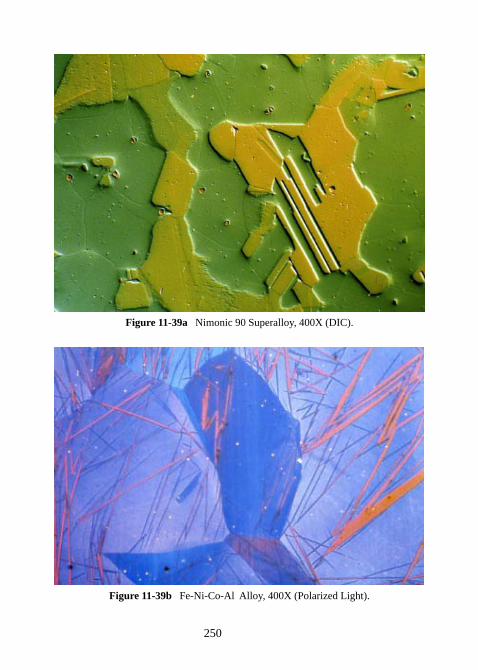
250
Figure 11-39a Nimonic 90 Superalloy, 400X (DIC).
Figure 11-39b Fe-Ni-Co-Al Alloy, 400X (Polarized Light).
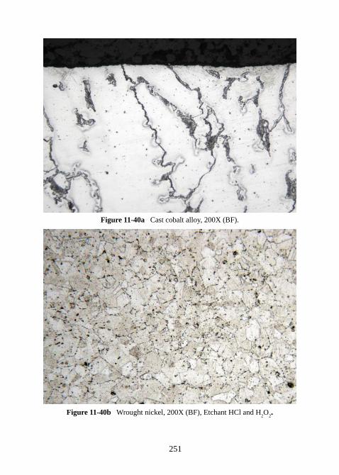
251
Figure 11-40a Cast cobalt alloy, 200X (BF).
Figure 11-40b Wrought nickel, 200X (BF), Etchant HCl and H2O
2.
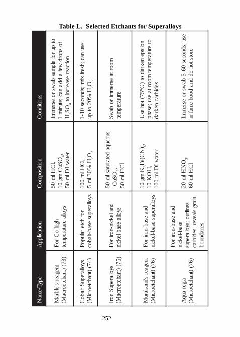
252
Table L. Selected Etchants for Superalloys
epyT/ema
Nnoitacilpp
Anoitisop
moC
snoitidnoC
tnegaers'elbra
M)37(
)tnahcteorcaM(
-hgiho
Cro
Fsyolla
erutarepmet
,lC
Hlm
05O
SuC
mg01
4, retaw
IDl
m05
otpu
rofelp
masba
wsro
esrem
mIfo
spordwef
adda
nac;etunim
1 H2
OS
4noitcaer
esaercniot
syollarepuStlabo
C)47(
)tnahcteorciM(
rofhcte
ralupoP
syollarepusesab-tlaboc
,lC
Hlm
001H
%03lm
52O
2
esunac;hserf
xim;sdnoces
01-1H
%02ot
pu2O
2
syollarepuS
norI)57(
)tnahcteorcaM(
dnalekcin-noriro
Fsyolla
esablekcin
suoeuqadetarutasl
m05
OSu
C4,
lC
Hlm
05
moortaesre
mmi
roba
wS
erutarepmet
tnegaers'i
makaruM
)67()tnahcteorci
M(dna
esab-noriro
Fsyollarepus
esab-lekcin
Kmg
013
)N
C(eF
6,,
HO
K01
retaw
IDl
m001
nolispenekrad
ot)
C°57(tohes
Uot
erutarepmet
moortaesu;esahp
sedibracnekrad
aigerauq
A)67(
)tnahcteorciM(
dnaesab-nori
roF
esab-lekcinseniltuo;syollarepus
niargslaever,sedibrac
seiradnuob
ON
Hlm
023,
lC
Hlm
06esu;sdnoces
06-5ba
wsro
esrem
mIerotston
oddna
doohe
mufni
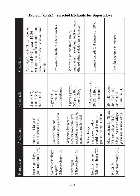
253
Table L (conti.). Selected Etchants for SuperalloysepyT/e
maN
noitacilppA
noitisopmo
Csnoitidno
C
syollarepuS
norI)67(
)tnahcteorcaM(
dnalekcin-noriro
Fsyolla
desablekcin
Hlm
52
OS
4,O
NHl
m3
3, lC
Hlm
29
Hdd
A2
OS
4ot
wolla,rits,lC
Hot O
NH
dda,looc3
03-01ba
ws;ton
od;doohe
mufni
esu;sdnocessnrut
noitulosneh
wdracsid;erots
egnaro
s'gnillaK
sselretaW
tnegaer)67 (
)tnahcteorciM(
dnaesab-nori
roF
syollarepusesab-lekcin
lCu
Cmg
52, ,l
CHl
m001
lonahtelm
001setuni
mwef
aot
baws
roesre
mmI
saigerecylG
)67()tnahcteorci
M(
larenegralupop
yreV
dnaesa b-nori
rofhcte
;syollarepusesab-lekcin
feilerni
emirp
am
mag
,lorecylgstrap
3,l
CH
strap3-2
ON
Htrap1
3
ybesu;erotston
od,hserfxi
M;sdnoces
06-5gnibba
wsro
noisrem
miegnaro
snrutnoitulos
nehw
dracsid
hctetnits'ahare
B)77(
)tnahcteorcriM(
fognihctetniT
sroloc;syollarepusa
mmag
dnasedibrac
detceffanuxirta
m,emirp
,dicacinelesl
m3-1
,lC
Hlm
03-02lonahtel
m001
C°02tasetuni
m4-1
elpmas
esrem
mI
eF-r
C-iN
)87()tnahcteorca
M(
dnaiN
roftnahcteorc aM
uC-i
N;syollaesab-i
N;syolla
eF-r
C-iN;syolla
syollarepusni
ezisniarg
,retaw
IDl
m05
,lonahtelm
05,l
CHl
m05
OSu
Cmg
014
setunim
otsdnoces
rofhct
E
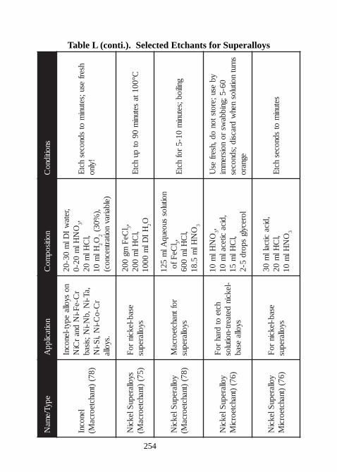
254
Table L (conti.). Selected Etchants for SuperalloysepyT/e
maN
noitacilppA
noitisopmo
Csnoitidno
C
lenocnI)87(
)tnahcteorcaM(
nosyolla
epyt-lenocnIr
C-eF-i
Ndna
rCi
N,aT-i
N,bN-i
N;sisabr
C-oC-i
N,iS-i
N.syolla
,retaw
IDl
m03-02
ON
Hlm
02-03,
,lC
Hlm
02Hl
m01
2O2
,)%03(
)elbairavnoitartnecnoc(
hserfesu;setuni
mot
sdnoceshct
E!ylno
syollarepuSlekci
N)57(
)tnahcteorcaM(
esab-lekcinro
Fsyollarepus
lCe
Fmg
0023,
,lC
Hlm
002H
IDl
m0001
2OC°001ta
setunim
09ot
puhct
E
yollarepuSlekci
N)87(
)tnahcteorcaM(
roftnahcteorcaM
syollarepus
noitulossuoeuq
Alm
521l
CeFfo
3,,l
CHl
m006
ON
Hlm
5.813
gniliob;setunim
01-5rof
hctE
yollarepuSlekci
N)67(
)tnahcteorciM
hcteot
drahro
F-lekcin
detaert-noitulossyolla
esab
ON
Hlm
013,
,dicacitecal
m01
,lC
Hlm
51lorecylg
spord5-2
ybesu;erotston
od,hserfes
U06-5;gnibba
wsro
noisrem
misnrut
noitulosneh
wdracsid;sdnoces
egnaro
yollarepuSlekci
N)67(
)tnahcteorciM
esab-lekcinro
Fsyollarepus
,dicacitcall
m03
,lC
Hlm
02O
NHl
m01
3
setunim
otsdnoces
hctE
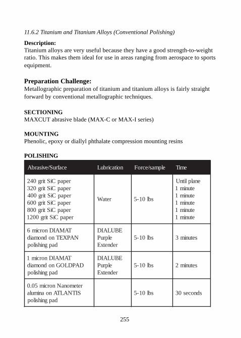
255
11.6.2 Titanium and Titanium Alloys (Conventional Polishing)
Description:Titanium alloys are very useful because they have a good strength-to-weightratio. This makes them ideal for use in areas ranging from aerospace to sportsequipment.
Preparation Challenge:Metallographic preparation of titanium and titanium alloys is fairly straightforward by conventional metallographic techniques.
SECTIONINGMAXCUT abrasive blade (MAX-C or MAX-I series)
MOUNTINGPhenolic, epoxy or diallyl phthalate compression mounting resins
POLISHING
ecafruS/evisarbA noitacirbuL elpmas/ecroF emiT
repapCiStirg042repapCiStirg023repapCiStirg004repapCiStirg006repapCiStirg008repapCiStirg0021
retaW sbl01-5
enalplitnUetunim1etunim1etunim1etunim1etunim1
TAMAIDnorcim6NAPXETnodnomaid
dapgnihsilop
EBULAIDelpruP
rednetxEsbl01-5 setunim3
TAMAIDnorcim1DAPDLOGnodnomaid
dapgnihsilop
EBULAIDelpruP
rednetxEsbl01-5 setunim2
retemonaNnorcim50.0SITNALTAnoanimula
dapgnihsilopsbl01-5 sdnoces03
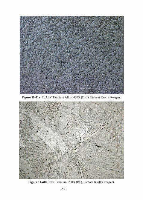
256
Figure 11-41a Ti6Al
4V Titanium Alloy, 400X (DIC), Etchant Kroll’s Reagent.
Figure 11-41b Cast Titanium, 200X (BF), Etchant Kroll’s Reagent.
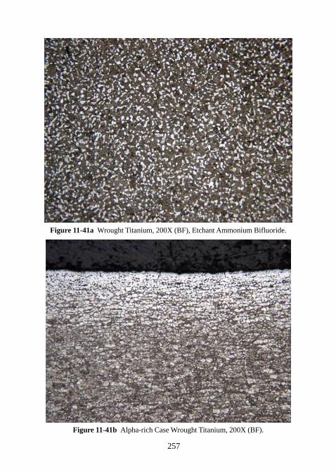
257
Figure 11-41a Wrought Titanium, 200X (BF), Etchant Ammonium Bifluoride.
Figure 11-41b Alpha-rich Case Wrought Titanium, 200X (BF).
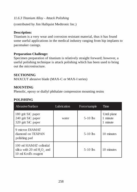
258
11.6.3 Titanium Alloy - Attack Polishing
(contributed by Jim Hallquist Medtronic Inc.)
Description:Titanium is a very wear and corrosion resistant material, thus it has foundsome useful applications in the medical industry ranging from hip implants topacemaker casings.
Preparation Challenge:Specimen preparation of titanium is relatively straight forward; however, auseful polishing technique is attack polishing which has been used to bringout the microstructure.
SECTIONINGMAXCUT abrasive blade (MAX-C or MAX-I series)
MOUNTINGPhenolic, epoxy or diallyl phthalate compression mounting resins
POLISHING
ecafruS/evisarbA noitacirbuL elpmas/ecroF emiT
repapCiStirg081repapCiStirg042repapCiStirg023
retaw sbl01-5enalplitnU
etunim1etunim1
TAMAIDnorcim9NAPXETnodnomaid
dapgnihsilopsbl01-5 setunim01
ladiollocTAMAISlm001Hlm02htiwacilis
2O
2dna
tnegaers'llorKlm01sbl01-5 setunim01
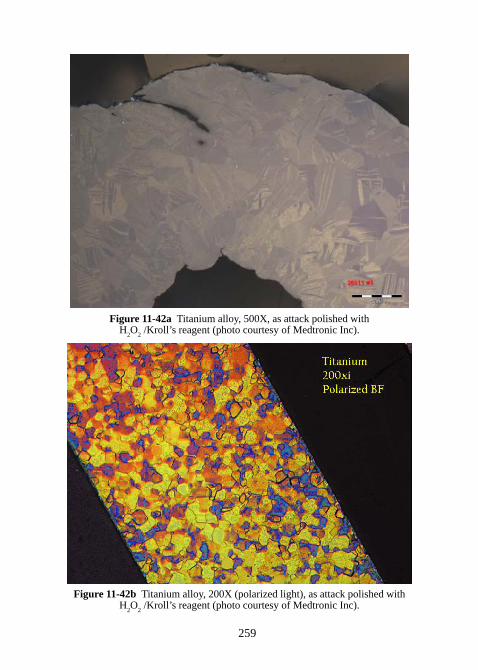
259
Figure 11-42a Titanium alloy, 500X, as attack polished withH
2O
2 /Kroll’s reagent (photo courtesy of Medtronic Inc).
Figure 11-42b Titanium alloy, 200X (polarized light), as attack polished withH
2O
2 /Kroll’s reagent (photo courtesy of Medtronic Inc).
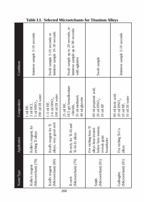
260
Table LI. Selected Microetchants for Titanium AlloysepyT/e
maN
noitacilppA
noitisopmo
Csnoitidno
C
tnegaers'relle
K)97(
)tnahcteorciM(
rof;tnegaers'relle
KsyollaiT
gnihcte
,FHl
m1
,lC
Hlm
3O
NHl
m5
3,reta
wI
Dlm
091
sdnoces01-3
elpmas
esrem
mI
tnegaers'llor
K)08(
)tnahcteorciM(
iTroftnegaer
s'llorK
hctedoog
yrev;syolla
,FHl
m3-1
ON
Hlm
6-23,
retaw
IDl
m001
rosdnoces
01-3elp
masba
wS
sdnoces03-01
elpmas
esrem
mi
hcte-R
)97()tnahcteorci
M(dnal
A-iTrof,hcte-
Rsyolla
rZ-l
A-iT
,FHl
m52
muinoklaznebmg
5.81,edirolhc
,lonahteml
m53
nirecylglm
04
ro,sdnoces02
otpu
elpmas
baw
Ssdnoces
09ot
puelp
masesre
mmi
noitatigahti
w
htim
S)18(
)tnahcteorciM(
iT-atebgnihcte
roF
detaert-taehsyolla
;susnartateb
wolebniarg
slaeverseiradnuob
,dicacinoiporpl
m06
ON
Hlm
023,
FHl
m01
elpmas
baw
S
rehguallaG
)18()tnahcteorci
M(u
C-iTgnihcte
roF
syolla
,dicacitcall
m06
ON
Hlm
023,
,FHl
m01
retaw
IDl
m01
sdnoces01-3
elpmas
esrem
mI
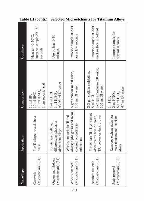
261
Table LI (conti.). Selected Microetchants for Titanium AlloysepyT/ e
maN
noit acil ppA
noitisopmo
Csnoiti dno
C
hci veruG
) 18()t nahct eorci
M(at eb
sl aever ;syoll ai Tr o
Fesahp
, FHl
m01
ON
Hlm
013,
Hlm
012
OS
4,di ca
ci ni ccusmg
1
,C°05- 04
ot t aeH
081- 02el p
masesre
mmi
sdnoces
nedl oH
dnanedg
O) 18(
)t nahct eorciM(
;syoll ai Tgni h ct e
r oF
nisesahp
set ait nereffi dsyoll a
at eb-ahpl a
,lC
Hlm
4- 1Hl
m1
2O
S4,
ret aw
IDl
m89- 59
01- 3, gnili obes
Uset uni
m
hct et nits' kce
W) 18(
)t nahct eorciM(
dnai Tr of
hct et nits' kce
Wsni
wtdna
sni argahpl a;syoll a
otgni dr occa
der ol ocnoit at neir o
, edi orulfi bmui no
mma
mg5
ret aw
IDl
m001
C°02t ael p
masesre
mmI
sdnoceswef
ar of
hct et nits' ahare
B) 18(
)t nahct eorciM(
sr ol oc;syoll ai Ttsac-sar o
F, neerg
r oeul b
xirt am
ahpl an
wor bkra d
r owoll ey
Ci T
, et adbyl om
mui dosmg
3- 2,l
CHl
m5
, edir oulfi bmui no
mma
mg2- 1
ret aw
IDl
m001
C°02t ael p
masesre
mmI
der ol ocsi
ecafruslit nu
l avomer
ni atS
) 28()t nahct eorci
M(
r ofsni ats t nahct e
sevome
Rmuinatit
dnamui natit tso
msyoll a
, FHl
m1
ON
Hlm
23,
Hlm
052O
2,ret a
wI
Dlm
74
r ofel p
masesre
mmI
sdnocesl areves
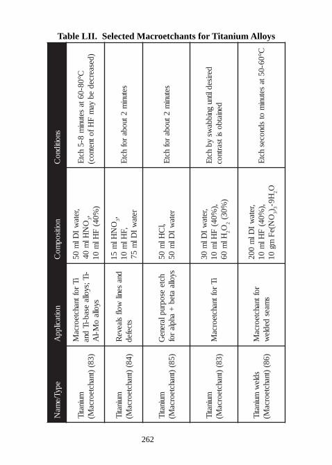
262
Table LII. Selected Macroetchants for Titanium Alloys
epyT/ema
Nnoitacilpp
Anoitisop
moC
snoitidnoC
muinatiT)38(
)tnahcteorcaM(
iTroftnahcteorca
M-iT;syolla
esab-iTdna
syollao
M-lA
,retaw
IDl
m05
ON
Hlm
043,
)%04(
FHl
m01
C°08-06tasetuni
m8-5
hctE
)desaercedeb
yam
FHfotnetnoc(
muinatiT)48(
)tnahcteorcaM(
dnasenil
wolfslaeve
Rstcefed
ON
Hlm
513,
,FHl
m01
retaw
IDl
m57
setunim
2tuobarof
hctE
muinatiT)58(
)tnahcteorcaM(
hcteesopruplarene
Gsyolla
ateb+
ahplaro f
,lC
Hlm
05reta
wI
Dlm
05setuni
m2tuoba
rofhct
E
muinatiT)38(
)tnahcteorcaM(
iTroftnahcteorca
M,reta
wI
Dlm
03,)
%04(F
Hlm
01Hl
m06
2O2
)%03(
derisedlitnugnibba
wsyb
hctE
deniatbositsartnoc
sdlew
muinatiT)68(
)tnahcteorcaM(
roftnahcteorcaM
smaes
dedlew
,retaw
IDl
m002
,)%04(
FHl
m01
ON(e
Fmg
013)
3H9-
2OC°06-05ta
setunim
otsdnoces
hctE
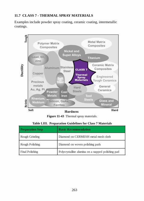
263
11.7 CLASS 7 - THERMAL SPRAY MATERIALS
Examples include powder spray coating, ceramic coating, intermetalliccoatings.
Figure 11-43 Thermal spray materials.
Table LIII. Preparation Guidelines for Class 7 Materials
petSnoitaraperP noitadnemmoceRcisaB
gnidnirGhguoR htolchsemlatemHSEMRECnodnomaiD
gnihsiloPhguoR sdapgnihsilopnevownodnomaiD
gnihsiloPlaniF dapgnihsilopdeppananoanimulaenillatsyrcyloP
264
Thermal Spray Coatings.Thermal spraying techniques are coating processes in which melted (orheated) materials are sprayed onto a surface. Thermal spraying can providethick coatings (approximate thickness range is 20 microns to several mm),over a large area. Coating materials available for thermal spraying includemetals, alloys, ceramics, plastics and composites. They are fed in powder orwire form, heated to a molten or semi-molten state and accelerated towardsthe substrates in the form of micron-size particles. Combustion or electricalarc discharge is usually used as the source of energy for thermal spraying.The coating quality is usually assessed by measuring its porosity, oxidecontent, macro and microhardness, bond strength and surface roughness.
Metallographic specimen preparation of thermal spray coatings is affected bythe specimen’s composition and deposition conditions. Microstructuralfeatures of interest include: porosity, flow, thickness and inclusions. Propermetallurgical preparation takes into account that the microstructure may beporous and perhaps somewhat brittle as a result of inadequate processing.Minimize damage with proper cutting.
The recommended initial grinding step is with either 15 or 30 microndiamond suspension on a metal mesh cloth. This step is very important andmust minimize damage or grain pull-out of a poorly deposited material. Thenext rough polishing stage must eliminate any remaining surface andsubsurface deformation to the specimen surface. Polycrystalline diamondsuspensions used in conjunction with a low-napped polishing pad result inminimal edge rounding and relief for the rough polishing stage. For the finalpolish, 0.05 micron Nanometer polycrystalline alumina provides an excellentsurface finish.
265
11.7.1 Thermal Spray Coatings
Preparation Challenge:Metallographic preparation of thermal spray coatings can be tricky; however,minimizing damage and understanding the chemical and mechanicalproperties of the coating and substrate will greatly improve successfulspecimen preparation.
SECTIONINGPrecision wafering with either diamond or CBN blades
MOUNTINGCastable epoxies or acrylics
POLISHING
ecafruS/evisarbA noitacirbuL elpmas/ecroF emiT
TAMAIDnorcim03HSEMRECnodnomaid
htolchsemlatem
EBULAIDrednetxE
sbl01-5 enalplitnU
TAMAIDnorcim9DAPYLOPnodnomaid
dapgnihsilop
EBULAIDelpruP
rednetxEsbl01-5 setunim3
TAMAIDnorcim6DAPDLOGnodnomaid
dapgnihsilop
EBULAIDelpruP
rednetxEsbl01-5 setunim3
TAMAIDnorcim1SITNALTAnodnomaid
dapgnihsilop
EBULAIDelpruP
rednetxEsbl01-5 setunim2
retemonaNnorcim50.0ETOCIRTnoanimula
dapgnihsilopsbl01-5 sdnoces54
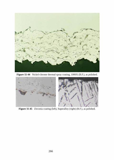
266
Figure 11-44 Nickel-chrome thermal spray coating, 1000X (B.F.), as polished.
Figure 11-45 Zirconia coating (left), Superalloy (right) (B.F.), as polished.
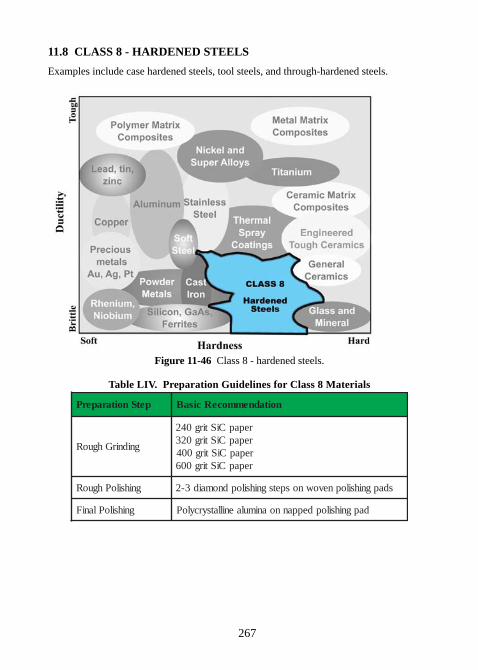
267
11.8 CLASS 8 - HARDENED STEELS
Examples include case hardened steels, tool steels, and through-hardened steels.
Figure 11-46 Class 8 - hardened steels.
Table LIV. Preparation Guidelines for Class 8 Materials
petSnoitaraperP noitadnemmoceRcisaB
gnidnirGhguoR
repapCiStirg042repapCiStirg023repapCiStirg004repapCiStirg006
gnihsiloPhguoR sdapgnihsilopnevownospetsgnihsilopdnomaid3-2
gnihsiloPlaniF dapgnihsilopdeppannoanimulaenillatsyrcyloP
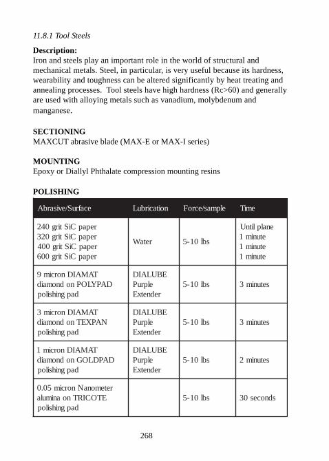
268
11.8.1 Tool Steels
Description:Iron and steels play an important role in the world of structural andmechanical metals. Steel, in particular, is very useful because its hardness,wearability and toughness can be altered significantly by heat treating andannealing processes. Tool steels have high hardness (Rc>60) and generallyare used with alloying metals such as vanadium, molybdenum andmanganese.
SECTIONINGMAXCUT abrasive blade (MAX-E or MAX-I series)
MOUNTINGEpoxy or Diallyl Phthalate compression mounting resins
POLISHING
ecafruS/evisarbA noitacirbuL elpmas/ecroF emiT
repapCiStirg042repapCiStirg023repapCiStirg004repapCiStirg006
retaW sbl01-5
enalplitnUetunim1etunim1etunim1
TAMAIDnorcim9DAPYLOPnodnomaid
dapgnihsilop
EBULAIDelpruP
rednetxEsbl01-5 setunim3
TAMAIDnorcim3NAPXETnodnomaid
dapgnihsilop
EBULAIDelpruP
rednetxEsbl01-5 setunim3
TAMAIDnorcim1DAPDLOGnodnomaid
dapgnihsilop
EBULAIDelpruP
rednetxEsbl01-5 setunim2
retemonaNnorcim50.0ETOCIRTnoanimula
dapgnihsilopsbl01-5 sdnoces03
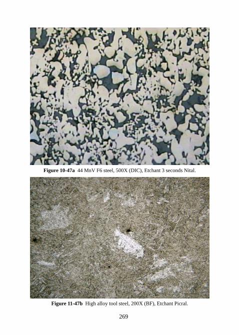
269
Figure 10-47a 44 MnV F6 steel, 500X (DIC), Etchant 3 seconds Nital.
Figure 11-47b High alloy tool steel, 200X (BF), Etchant Picral.
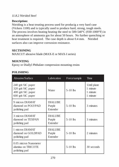
270
11.8.2 Nitrided Steel
Description:Nitriding is a heat treating process used for producig a very hard case(Vickers 1100) and is typically used to produce hard, strong, tough steels.The process involves heating heating the steel to 500-540°C (930-1000°F) inan atmosphere of ammonia gas for about 50 hours. No further quenching orheat treatment is required. The case depth is about 0.4 mm. Nitridedsurfaces also can improve corrsosion resistance.
SECTIONINGMAXCUT abrasive blade (MAX-E or MAX-I series)
MOUNTINGEpoxy or Diallyl Phthalate compression mounting resins
POLISHING
ecafruS/evisarbA noitacirbuL elpmas/ecroF emiT
repapCiStirg042repapCiStirg023repapCiStirg004repapCiStirg006
retaW sbl01-5
enalplitnUetunim1etunim1etunim1
TAMAIDnorcim9DAPYLOPnodnomaid
dapgnihsilop
EBULAIDelpruP
rednetxEsbl01-5 setunim3
TAMAIDnorcim3NAPXETnodnomaid
dapgnihsilop
EBULAIDelpruP
rednetxEsbl01-5 setunim3
TAMAIDnorcim1DAPDLOGnodnomaid
dapgnihsilop
EBULAIDelpruP
rednetxEsbl01-5 setunim2
retemonaNnorcim50.0ETOCIRTnoanimula
dapgnihsilopsbl01-5 sdnoces03
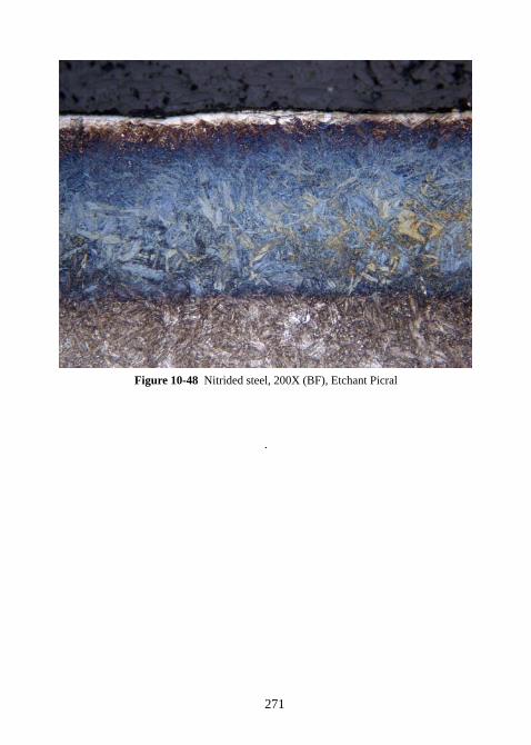
271
Figure 10-48 Nitrided steel, 200X (BF), Etchant Picral
.
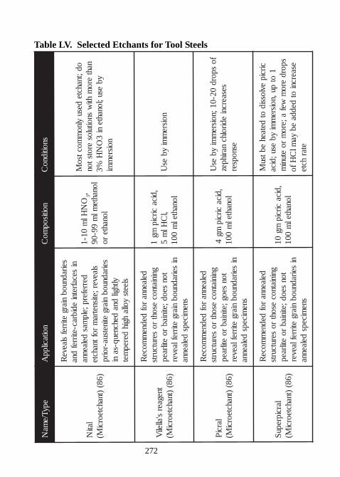
272
Table LV. Selected Etchants for Tool SteelsepyT/ e
maN
noit acil ppA
noitisopmo
Csnoiti dno
C
l atiN
) 68()t nahct eorci
M(
seiradnuobni arg
etirrefsl aeve
Rni
secafret niedi brac-etirref
dnaderrefer p; el p
masdel aenna
sl aever ; etisnetram
r of t nahct eseiradnuob
ni argeti netsua-r oir p
ylt hgildna
dehcneuq-sani
sl eetsyoll a
hgi hderep
met
ON
Hlm
01- 13,
l onaht eml
m99- 09
l onaht er o
od;t nahct edesu
yl nom
moctsoM
nahter o
mhti
wsnoit ul os
er ots t onyb
esu;l onaht eni
3O
NH
%3noisre
mmi
t negaers' all eli
V) 68(
)t nahct eorciM(
del aennar of
dednem
moceR
gni ni at nocesoht
r oserut curts
t onseod; eti ni ab
r oetilraep
niseiradnuob
ni argetirref l aever
snemi ceps
del aenna
, di cacirci p
mg1
,lC
Hlm
5l onaht el
m001
noisrem
miyb
esU
l arciP
) 68()t nahct eorci
M(
del aennar of
dednem
moceR
gni ni at nocesoht
r oserut curts
t onseog; eti ni ab
r oetilraep
niseiradnuob
ni argetirref l aever
snemi ceps
del aenna
, di cacirci p
mg4
l onaht elm
001
f ospor d
02- 01; noisrem
miyb
esU
sesaercniedir ol hc
nari hpezesnopser
l arci prepuS
) 68()t nahct eorci
M(
del aennar of
dednem
moceR
gni ni at nocesoht
r oserut curts
t onseod; eti ni ab
r oetilraep
niseiradnuob
ni argetirref l aever
snemi ceps
del aenna
, di cacirci p
mg01
l onaht elm
001
circi pevl ossi d
otdet aeh
ebtsuM
1ot
pu, noisrem
miyb
esu; di caspor d
er om
wefa; er o
mr o
et unim
esaercniot
deddaeb
yaml
CHf o
et arhct e
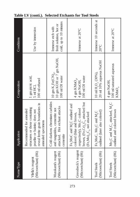
273
Table LV (conti.). Selected Etchants for Tool SteelsepyT/e
maN
noitacilppA
noitisopmo
Csnoitidno
C
tnegaers'alleli
V)68(
)tnahcteorciM(
delaennarof
dednem
moceR
gniniatnocesoht
roserutcurts
tonseod; etiniab
roetilraep
niseiradnuob
niargetirreflaever
snemiceps
delaenna
,dicacircip
mg1
,lC
Hlm
5lonahtel
m001
noisrem
miyb
esU
tnegaers'i
makaruM
)68()tnahcteorci
M(
sedibracmui
morhcsnekrad-dlo
Cton
etitnemec,seditsgnut
dnaskcattatnahcteto
H.dekcattaetitne
mec
Kmg
013
)N
C(eF
6,,
HOa
Nmg
7ro
HO
Kmg
01reta
wI
Dlm
001
htiw
hcteesre
mmI
rotoh,noituloshserf
setunim
01ot
pu,dloc
tnegaers'kcebsoer
G)68(
)tnahcteorciM(
eF
2M
dnaCo
M6
dnadeniltuo
C,n
worbdna
eulb(deroloc
oM,)ylevitcepser
2deroloc
C)r
C,eF(,n
worb32C
6tub
dekcatta)o
M,eF(
32C
6dekcattaton
OnM
Kmg
44, ,
HOa
Nmg
4reta
wI
Dlm
001C°02ta
esrem
mI
sleetSlooT
)68()tnahcteorci
M(e
F2
oM,
CoM
2M
dnaC
6C)deroloc
oslaretal(
deniltuoHl
m01
2O2
,)%03(
HOa
Nsuoeuqa
%01lm
02ta
sdnoces01
esrem
mIC°02
sleetSlooT
)68()tnahcteorci
M(o
M2
Mdna
C7C
3M,dekcatta
6Cn
worbderoloc
dnadeniltuo
,H
OaN
mg4
suoeuqadetarutasl
m001
OnM
K4
C°02taesre
mmI
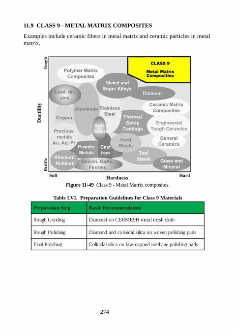
274
11.9 CLASS 9 - METAL MATRIX COMPOSITES
Examples include ceramic fibers in metal matrix and ceramic particles in metalmatrix.
Figure 11-49 Class 9 - Metal Matrix composites.
Table LVI. Preparation Guidelines for Class 9 Materials
petSnoitaraperP noitadnemmoceRcisaB
gnidnirGhguoR htolchsemlatemHSEMRECnodnomaiD
gnihsiloPhguoR sdapgnihsilopnevownoacilisladiollocdnadnomaiD
gnihsiloPlaniF sdapgnihsilopenahterudeppan-wolnoacilisladiolloC
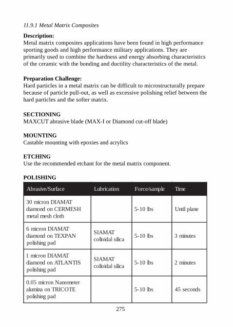
275
11.9.1 Metal Matrix Composites
Description:Metal matrix composites applications have been found in high performancesporting goods and high performance military applications. They areprimarily used to combine the hardness and energy absorbing characteristicsof the ceramic with the bonding and ductility characteristics of the metal.
Preparation Challenge:Hard particles in a metal matrix can be difficult to microstructurally preparebecause of particle pull-out, as well as excessive polishing relief between thehard particles and the softer matrix.
SECTIONINGMAXCUT abrasive blade (MAX-I or Diamond cut-off blade)
MOUNTINGCastable mounting with epoxies and acrylics
ETCHINGUse the recommended etchant for the metal matrix component.
POLISHING
ecafruS/evisarbA noitacirbuL elpmas/ecroF emiT
TAMAIDnorcim03HSEMRECnodnomaid
htolchsemlatemsbl01-5 enalplitnU
TAMAIDnorcim6NAPXETnodnomaid
dapgnihsilop
TAMAISacilisladiolloc
sbl01-5 setunim3
TAMAIDnorcim1SITNALTAnodnomaid
dapgnihsilop
TAMAISacilisladiolloc
sbl01-5 setunim2
retemonaNnorcim50.0ETOCIRTnoanimula
dapgnihsilopsbl01-5 sdnoces54
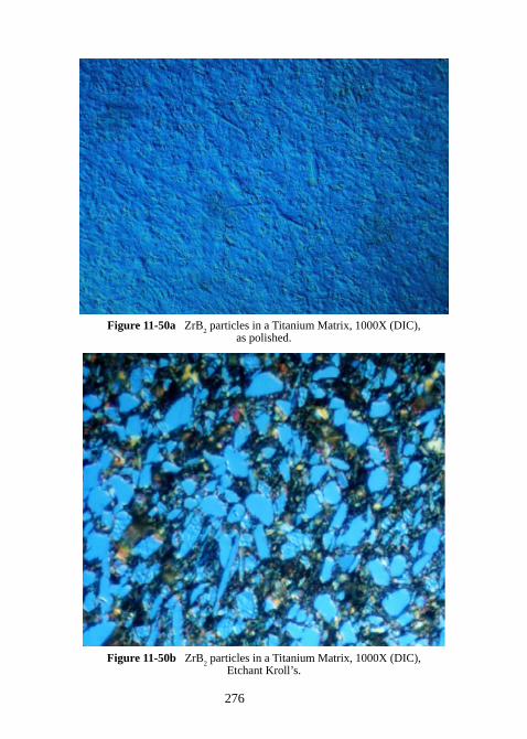
276
Figure 11-50a ZrB2 particles in a Titanium Matrix, 1000X (DIC),
as polished.
Figure 11-50b ZrB2 particles in a Titanium Matrix, 1000X (DIC),
Etchant Kroll’s.
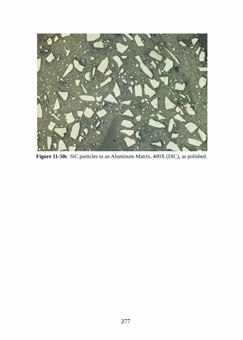
277
Figure 11-50c SiC particles in an Aluminum Matrix, 400X (DIC), as polished.
278
11.9.2 Metal Matrix Composite - Metal Injection Molding (MIM)
(contributed by Jim Hallquist Medtronic Inc.)
Description:Metal Injection Molding (MIM) is a manufacturing process which combinesthe technology of powder metallurgy and plastic injection molding in order toproduce complex parts. When combined with ceramic particles, these partsalso become very hard and wear resistant. The products of metal injectionmolding have very high densities (up to 98% density of wrought metal) and ina broad range of applications, including medical, dental, firearms, aerospaceand automotive.
Preparation Challenge:Hard particles in a metal matrix can be difficult to microstructurally preparebecause of particle pull-out, as well as excessive polishing relief between thehard particles and the softer matrix.
MOUNTINGCastable mounting with epoxies and acrylics
ETCHINGUse the recommended etchant for the metal matrix component.
POLISHING
ecafruS/evisarbA noitacirbuL elpmas/ecroF emiT
repapCiStirg081repapCiStirg042repapCiStirg023
retaw sbl01-5enalplitnU
etunim1etunim1
TAMAIDnorcim9NAPXETnodnomaid
dapgnihsilop
TAMAISacilisladiolloc
sbl01-5 setunim01
ladiollocTAMAISlm001Hlm02htiwacilis
2O
2dna
tnegaeRs'llorKlm01sbl01-5 setunim01
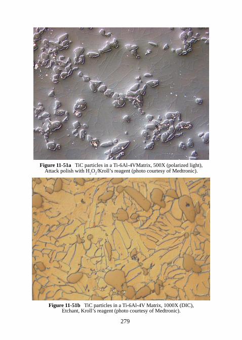
279
Figure 11-51a TiC particles in a Ti-6Al-4VMatrix, 500X (polarized light),Attack polish with H
2O
2/Kroll’s reagent (photo courtesy of Medtronic).
Figure 11-51b TiC particles in a Ti-6Al-4V Matrix, 1000X (DIC),Etchant, Kroll’s reagent (photo courtesy of Medtronic).
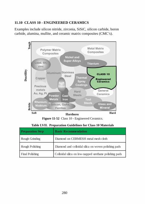
280
11.10 CLASS 10 - ENGINEERED CERAMICS
Examples include silicon nitride, zirconia, SiSiC, silicon carbide, boroncarbide, alumina, mullite, and ceramic matrix composites (CMC’s).
Figure 11-52 Class 10 - Engineered Ceramics.
Table LVII. Preparation Guidelines for Class 10 Materials
petSnoitaraperP noitadnemmoceRcisaB
gnidnirGhguoR htolchsemlatemHSEMRECnodnomaiD
gnihsiloPhguoR sdapgnihsilopnevownoacilisladiollocdnadnomaiD
gnihsiloPlaniF sdapgnihsilopenahterudeppan-wolnoacilisladiolloC
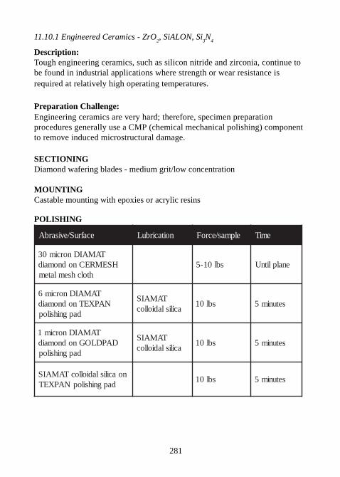
281
11.10.1 Engineered Ceramics - ZrO2, SiALON, Si
3N
4
Description:Tough engineering ceramics, such as silicon nitride and zirconia, continue tobe found in industrial applications where strength or wear resistance isrequired at relatively high operating temperatures.
Preparation Challenge:Engineering ceramics are very hard; therefore, specimen preparationprocedures generally use a CMP (chemical mechanical polishing) componentto remove induced microstructural damage.
SECTIONINGDiamond wafering blades - medium grit/low concentration
MOUNTINGCastable mounting with epoxies or acrylic resins
POLISHING
ecafruS/evisarbA noitacirbuL elpmas/ecroF emiT
TAMAIDnorcim03HSEMRECnodnomaid
htolchsemlatemsbl01-5 enalplitnU
TAMAIDnorcim6NAPXETnodnomaid
dapgnihsilop
TAMAISacilisladiolloc
sbl01 setunim5
TAMAIDnorcim1DAPDLOGnodnomaid
dapgnihsilop
TAMAISacilisladiolloc
sbl01 setunim5
noacilisladiollocTAMAISdapgnihsilopNAPXET
sbl01 setunim5
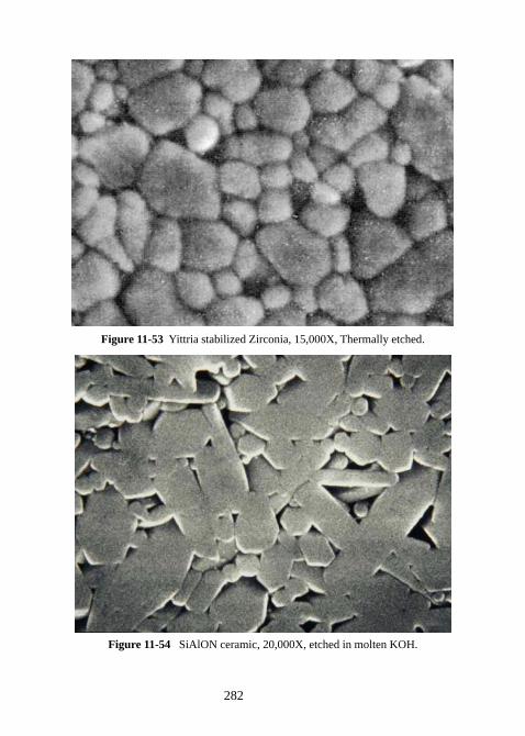
282
Figure 11-53 Yittria stabilized Zirconia, 15,000X, Thermally etched.
Figure 11-54 SiAlON ceramic, 20,000X, etched in molten KOH.
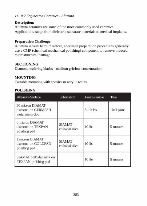
283
11.10.2 Engineered Ceramics - Alumina
Description:Alumina ceramics are some of the most commonly used ceramics.Applications range from dielectric substrate materials to medical implants.
Preparation Challenge:Alumina is very hard; therefore, specimen preparation procedures generallyuse a CMP (chemical mechanical polishing) component to remove inducedmicrostructural damage.
SECTIONINGDiamond wafering blades - medium grit/low concentration
MOUNTINGCastable mounting with epoxies or acrylic resins
POLISHING
ecafruS/evisarbA noitacirbuL elpmas/ecroF emiT
TAMAIDnorcim03HSEMRECnodnomaid
htolchsemlatemsbl01-5 enalplitnU
TAMAIDnorcim6NAPXETnodnomaid
dapgnihsilop
TAMAISacilisladiolloc
sbl01 setunim5
TAMAIDnorcim1DAPDLOGnodnomaid
dapgnihsilop
TAMAISacilisladiolloc
sbl01 setunim5
noacilisladiollocTAMAISdapgnihsilopNAPXET
sbl01 setunim5
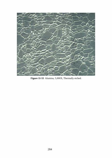
284
Figure 11-55 Alumina, 5,000X, Thermally etched.
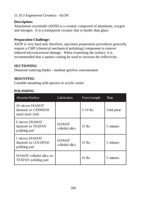
285
11.10.3 Engineered Ceramics - ALON
Description:Aluminium oxynitride (AlON) is a ceramic composed of aluminum, oxygenand nitrogen. It is a transparent ceramic that is harder than glass.
Preparation Challenge:AlON is very hard and, therefore, specimen preparation procedures generallyrequire a CMP (chemical mechanical polishing) component to removeinduced microstructural damage. When examining the surface, it isrecommended that a sputter coating be used to increase the reflectivity.
SECTIONINGDiamond wafering blades - medium grit/low concentration
MOUNTINGCastable mounting with epoxies or acrylic resins
POLISHING
ecafruS/evisarbA noitacirbuL elpmas/ecroF emiT
TAMAIDnorcim03HSEMRECnodnomaid
htolchsemlatemsbl01-5 enalplitnU
TAMAIDnorcim6NAPXETnodnomaid
dapgnihsilop
TAMAISacilisladiolloc
sbl01 setunim5
TAMAIDnorcim1DAPDLOGnodnomaid
dapgnihsilop
TAMAISacilisladiolloc
sbl01 setunim5
noacilisladiollocTAMAISdapgnihsilopNAPXET
sbl01 setunim5
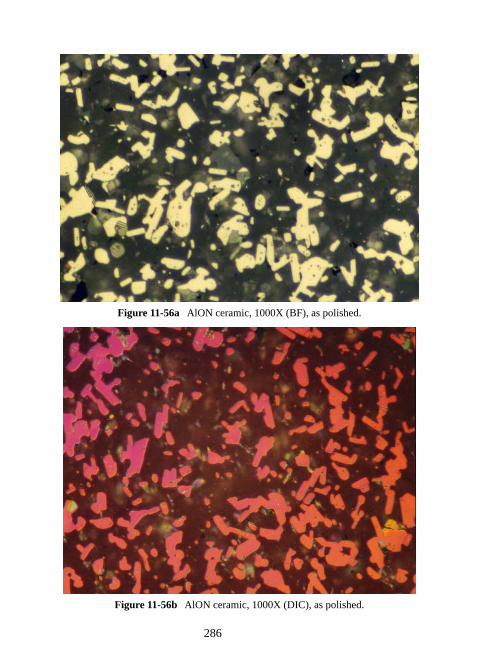
286
Figure 11-56a AlON ceramic, 1000X (BF), as polished.
Figure 11-56b AlON ceramic, 1000X (DIC), as polished.
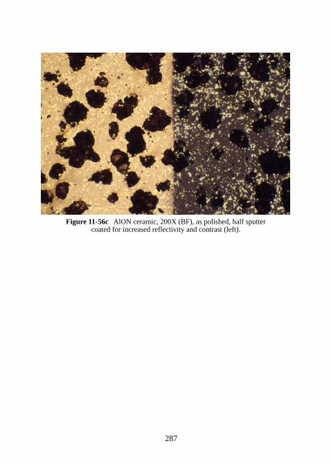
287
Figure 11-56c AlON ceramic, 200X (BF), as polished, half sputtercoated for increased reflectivity and contrast (left).
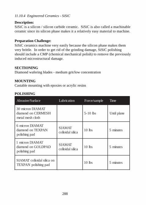
288
11.10.4 Engineered Ceramics - SiSiC
Description:SiSiC is a silicon / silicon carbide ceramic. SiSiC is also called a machinableceramic since its silicon phase makes it a relatively easy material to machine.
Preparation Challenge:SiSiC ceramics machine very easily because the silicon phase makes themvery brittle. In order to get rid of the grinding damage, SiSiC polishingshould include a CMP (chemical mechanical polish) to remove the previouslyinduced microstructural damage.
SECTIONINGDiamond wafering blades - medium grit/low concentration
MOUNTINGCastable mounting with epoxies or acrylic resins
POLISHING
ecafruS/evisarbA noitacirbuL elpmas/ecroF emiT
TAMAIDnorcim03HSEMRECnodnomaid
htolchsemlatemsbl01-5 enalplitnU
TAMAIDnorcim6NAPXETnodnomaid
dapgnihsilop
TAMAISacilisladiolloc
sbl01 setunim5
TAMAIDnorcim1DAPDLOGnodnomaid
dapgnihsilop
TAMAISacilisladiolloc
sbl01 setunim5
noacilisladiollocTAMAISdapgnihsilopNAPXET
sbl01 setunim5
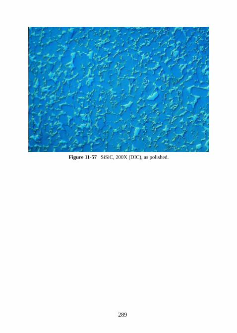
289
Figure 11-57 SiSiC, 200X (DIC), as polished.
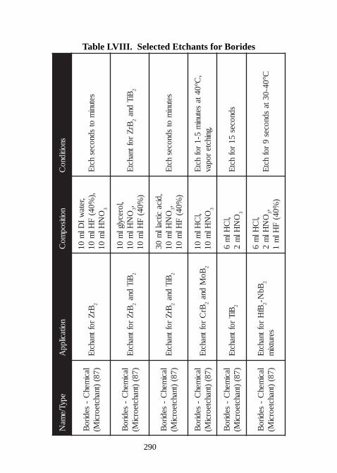
290
Table LVIII. Selected Etchants for Borides
epyT/ema
Nnoitacilpp
Anoitisop
moC
snoitidnoC
lacimeh
C-
sediroB
)78()tnahcteorci
M(Br
Zroftnahct
E2
,retaw
IDl
m01
,)%04(
FHl
m01
ON
Hlm
013
setunim
otsdnoces
hctE
lacimeh
C-
sediroB
)78()tnahcteorci
M(Br
Zroftnahct
E2
BiTdna
2
,lorecylglm
01O
NHl
m01
3,)
%04(F
Hlm
01Br
Zroftnahct
E2
BiTdna
2
lacimeh
C-
sediroB
)78()tnahcteorci
M(Br
Zroftnahct
E2
BiTdna
2
,dicacitcall
m03
ON
Hlm
013,
)%04(
FHl
m01
setunim
otsdnoces
hctE
lacimeh
C-
sediroB
)78()tnahcteorci
M(Br
Croftnahct
E2
BoM
dna2
,lC
Hlm
01O
NHl
m01
3
,C°04ta
setunim
5-1rof
hctE
.gnihcteropav
lacimeh
C-
sediroB
)78()tnahcteorci
M(BiT
roftnahctE
2
,lC
Hlm
6O
NHl
m2
3
sdnoces51
rofhct
E
lacimeh
C-
sediroB
)78()tnahcteorci
M(Bf
Hroftnahct
E2
BbN-
2
serutxim
,lC
Hlm
6O
NHl
m2
3,)
%04(F
Hlm
1C°04-03ta
sdnoces9
rofhct
E
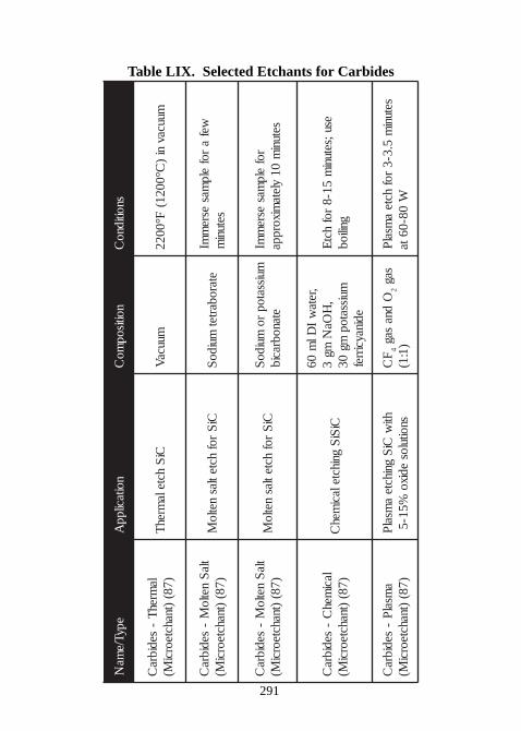
291
Table LIX. Selected Etchants for Carbides
epyT/ema
Nnoitacilpp
Anoitisop
moC
snoitidnoC
lamreh
T-
sedibraC
)78()tnahcteorci
M(Ci
Shctela
mrehT
muucaV
muucavni
)C°0021(
F°0022
tlaS
netloM
-sedibr a
C)78(
)tnahcteorciM(
CiS
rofhctetlas
netloM
etarobartetmuido
Swef
arof
elpmas
esrem
mIsetuni
m
tlaS
netloM
-sedibra
C)78(
)tnahcteorciM(
CiS
rofhctetlas
netloM
muissatopro
muidoS
etanobracibrof
elpmas
esrem
mIsetuni
m01
yletamixorppa
lacimeh
C-
sedibraC
)78()tnahcteorci
M(Ci
SiS
gnihctelacimeh
C
,retaw
IDl
m06
,H
OaN
mg3
muissatopmg
03edinaycirref
esu;setunim
51-8rof
hctE
gniliob
amsal
P-
sedibraC
)78()tnahcteorci
M(hti
wCi
Sgnihcte
amsal
Psnoitulos
edixo%5 1-5
FC
4O
dnasag
2sag
)1:1(setuni
m5.3-3
rofhcte
amsal
PW
08-06ta
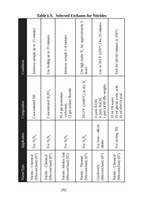
292
Table LX. Selected Etchants for Nitrides
epyT/ema
Nnoitacilpp
Anoitisop
moC
snoitidnoC
lacimeh
C-
edirtiN
)78()tnahcteorci
M(i
Sro
F3N
4F
Hdetartnecno
Csetuni
m51
otpu
elpmas
esrem
mI
lacimeh
C-
edirtiN
)78()tnahcteorci
M(i
Sro
F3N
4H
detartnecnoC
3O
P4
setunim
51ot
pugniliob
esU
tlaS
netloM-
edirtiN
)78()tnahcteorci
M(i
Sro
F3N
4
muissatopmg
4.59,etanobrac
ediroulfmuidos
mg21
setunim
4-1elp
masesre
mmI
lamreh
T-
edirtiN
)78()tnahcteorci
M(i
Sro
F3N
4N
yrdni
)C°0061(
F°21922
Nytirup
hgihes
U2
5yleta
mixorpparof
sruoh
hcivokserG
)78()tnahcteorci
M(nocilis
-ateb
roF
edirtin
,H
OK
strap4
,H
OaN
strap4
)thgiew
yB(
HOi
Ltrap1
setunim
02rof
)C°002(
F293ta
esU
lacimeh
C-
edirtiN
)78()tnahcteorci
M(NiT
gnihctero
F,reta
wI
Dlm
01,dica
citecalaicalglm
01dica
3O
NHl
m01
C°001tasetuni
m06-04
rofhct
E
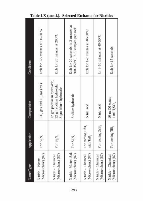
293
Table LX (conti.). Selected Etchants for Nitrides
epyT/ema
Nnoitacilpp
Anoitisop
moC
snoitidnoC
amsal
P-
edirtiN
)78()tnahcteorci
M(i
Sro
F3N
4F
C4
Odna
sag2
)1:2(sag
W08-06ta
setunim
5-3rof
hctE
lacimeh
C-
edirtiN
)78()tnahcteorci
M(i
Sro
F3N
4
,edixordyhmuissatop
mg21
,edixordyhmuidos
mg21
edixordyhmuihtil
mg3
C°002tasetuni
m02
rofhct
E
tlaS
netloM-
edirtiN
)78()tnahcteorci
M(i
Sro
F3N
4edixordyh
muidoS
tasetuni
m3
otsdnoces
02rof
hctE
tlem
repselp
mas3-2,
C°053-003
lacimeh
C-
edirtiN
)78()tnahcteorci
M(Bf
Hgnihcte
roF
2
BaThti
w2
dicacirti
NC°05-04ta
setunim
2-1rof
hctE
lacimeh
C-
edirtiN
)78()tnahcteorci
M(Br
Zgnihcte
roF
2dica
cirtiN
C°05-04tasetuni
m01-8
rof
lacimeh
C-
edirtiN
)78()tnahcteorci
M(BiT
gnihctero
F2
,retaw
IDl
m01
Hlm
12
OS
4
sdnoces51
rofhct
E
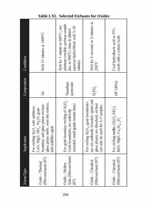
294
Table LXI. Selected Etchants for Oxides
epyT/ema
Nnoitacilpp
Anoitisop
moC
snoitidnoC
lamrehT
-edix
O)78(
)tnahcteorciM(
lA
gnihcteroF
2O3
:sevitiddahti
wOiS,
OgM,
OaC
2a
N,2
niarg;O
.tnahcteesahp
ssalgdna
yradnuob,ecafrus
ehtste
w,stlem
esahpssalg
niagaseifidilos
dna
riA
C°0041tasetuni
m51
hctE
netloM
-edix
O)tnahcteorci
M(stlaS)78(
lAfo
gnihcteyradnuob
niargroF
2O3.
ylmrofinu
eraseiradnuob
niarG
tcatninia
mersniarglla
ms;delaever
muidanaVedixotnep
esu;C°009ta
etunim
1rof
hctEelp
mastaeherp;elbicurcmunitalp
detulidni
esnir;C°009
otosla
01-5dica
cirolhcordyhsuoeuqa
setunim
lacimeh
C-
e dixO
)78()tnahcteorci
M(
lA
gnihcteroF
2O3
seiradnuobniarg;
dnalenips;delaeveryl
mrofinutonera
tnahcte,devlossidera
sesahpssalg
selpmas
3-2rof
desueb
ylnonac
H3
OP4
tasetuni
m3
otsdnoces
5rof
hctEC°052
lacimeh
C-
edixO
)78()tnahcteorci
M(l
A(etillu
mgnihcte
roF2O
3OiS-
2,)
aC,
OgM,
OeB
2rZ
)x-1(O
y
)%04(
FH
;C°0
otdica
ciroulfordyhlooC
baws
nottoca
htiw
baws
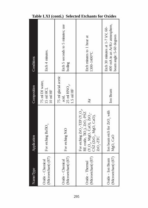
295
Table LXI (conti.) Selected Etchants for Oxides
epyT/ema
Nnoitacilpp
Anoitisop
moC
snoitidnoC
lacimeh
C-
edixO
)78()tnahcteorci
M(OiTa
Bgnihcte
roF
3
,retaw
IDl
m57
,lC
Hlm
51F
Hlm
01.setuni
m4
hctE
lacimeh
C-
edixO
)78()tnahcteorci
M(Oi
Ngnihcte
roF
citecalaicalglm
57,dica
ON
Hlm
523,
FHl
m5.1
esu;setunim
5ot
sdnoces5
hctE
gniliob
lamreh
T-
edixO
)78()tnahcteorci
M(
OrZ
gnihctero
F2
Y(P
ZT-
2O3,
OiT,edixoE
R2
OrZ,)
2Z
SP-
Y(2O
3Or
Z,)Oa
C,Og
M,2-
OrZ(
ZS
C2
,)Oa
C,Og
M,Or
Z2
CT
Z-
riA
taruoh
1ot
setunim
hctE
C°0041-0031
maeB
noI-
edixO
)78()tnahcteorci
M(Or
Zrof
hctemaeb
noI2
htiw
OaC,
OgM
maeB
noI-06,
Vk7-1ta
setunim
03hct
E,erehpso
mtar
K/rA
nani
Am
004seerged
06-5:elgnamaeb
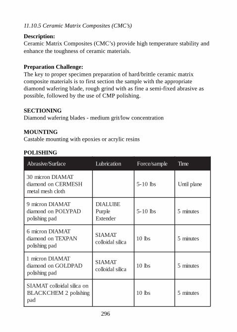
296
11.10.5 Ceramic Matrix Composites (CMC’s)
Description:Ceramic Matrix Composites (CMC’s) provide high temperature stability andenhance the toughness of ceramic materials.
Preparation Challenge:The key to proper specimen preparation of hard/brittle ceramic matrixcomposite materials is to first section the sample with the appropriatediamond wafering blade, rough grind with as fine a semi-fixed abrasive aspossible, followed by the use of CMP polishing.
SECTIONINGDiamond wafering blades - medium grit/low concentration
MOUNTINGCastable mounting with epoxies or acrylic resins
POLISHING
ecafruS/evisarbA noitacirbuL elpmas/ecroF emiT
TAMAIDnorcim03HSEMRECnodnomaid
htolchsemlatemsbl01-5 enalplitnU
TAMAIDnorcim9DAPYLOPnodnomaid
dapgnihsilop
EBULAIDelpruP
rednetxEsbl01-5 setunim5
TAMAIDnorcim6NAPXETnodnomaid
dapgnihsilop
TAMAISacilisladiolloc
sbl01 setunim5
TAMAIDnorcim1DAPDLOGnodnomaid
dapgnihsilop
TAMAISacilisladiolloc
sbl01 setunim5
noacilisladiollocTAMAISgnihsilop2MEHCKCALB
dapsbl01 setunim5
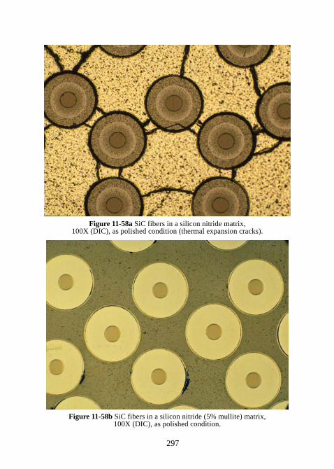
297
Figure 11-58a SiC fibers in a silicon nitride matrix,100X (DIC), as polished condition (thermal expansion cracks).
Figure 11-58b SiC fibers in a silicon nitride (5% mullite) matrix,100X (DIC), as polished condition.
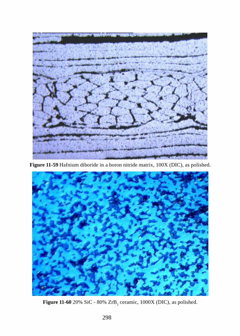
298
Figure 11-59 Hafnium diboride in a boron nitride matrix, 100X (DIC), as polished.
Figure 11-60 20% SiC - 80% ZrB2 ceramic, 1000X (DIC), as polished.
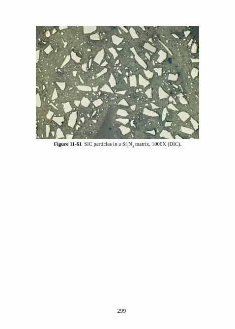
299
Figure 11-61 SiC particles in a Si3N
4 matrix, 1000X (DIC).
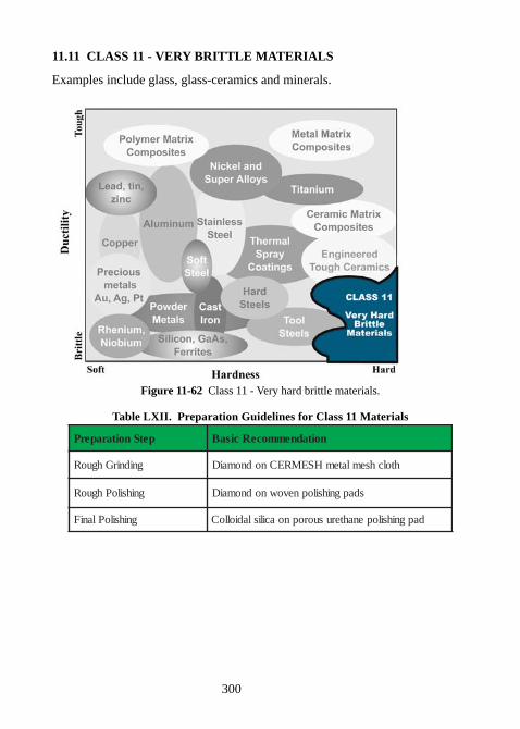
300
11.11 CLASS 11 - VERY BRITTLE MATERIALS
Examples include glass, glass-ceramics and minerals.
Figure 11-62 Class 11 - Very hard brittle materials.
Table LXII. Preparation Guidelines for Class 11 Materials
petSnoitaraperP noitadnemmoceRcisaB
gnidnirGhguoR htolchsemlatemHSEMRECnodnomaiD
gnihsiloPhguoR sdapgnihsilopnevownodnomaiD
gnihsiloPlaniF dapgnihsilopenahterusuoropnoacilisladiolloC
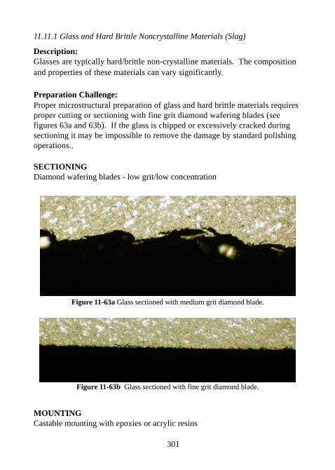
301
11.11.1 Glass and Hard Brittle Noncrystalline Materials (Slag)
Description:Glasses are typically hard/brittle non-crystalline materials. The compositionand properties of these materials can vary significantly.
Preparation Challenge:Proper microstructural preparation of glass and hard brittle materials requiresproper cutting or sectioning with fine grit diamond wafering blades (seefigures 63a and 63b). If the glass is chipped or excessively cracked duringsectioning it may be impossible to remove the damage by standard polishingoperations..
SECTIONINGDiamond wafering blades - low grit/low concentration
Figure 11-63a Glass sectioned with medium grit diamond blade.
Figure 11-63b Glass sectioned with fine grit diamond blade.
MOUNTINGCastable mounting with epoxies or acrylic resins
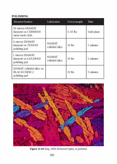
302
POLISHING
ecafruS/evisarbA noitacirbuL elpmas/ecroF emiT
TAMAIDnorcim03HSEMRECnodnomaid
htolchsemlatemsbl01-5 enalplitnU
TAMAIDnorcim6NAPXETnodnomaid
dapgnihsilop
TAMAISacilisladiolloc
sbl01 setunim5
TAMAIDnorcim1DAPDLOGnodnomaid
dapgnihsilop
TAMAISacilisladiolloc
sbl01 setunim5
noacilisladiollocTAMAIS2MEHCKCALB
dapgnihsilopsbl01 setunim5
Figure 11-64 Slag, 100X (Polarized light), as polished.
303
11.11.2 Glass-Ceramics (Alumino-Silicate)
Description:Glass ceramics are unique materials that have very samll crystallinestructures. The primary advantage of glass ceramics is that they produce veryinteresting thermochemical properties because they are impervious to thermalshock.
Preparation Challenge:Proper microstructural preparation of these materials requires minimizingdamage during cutting or sectioning. Therefore, the most important step in thepreparation of glass ceramics is sectioning. If the glass ceramic is chipped orexcessively cracked during sectioning, it may be impossible to remove thisdamage. Wafer sectioning with a fine grit diamond wafering blade isessential.
Planar grinding is accomplished with diamond on a metal mesh cloth tominimize cracking and subsurface damage. For rough polishing, the use of alow-napped polishing pad with polycrystalline diamond and colloidal silicaeliminates most of the surface and subsurface damage. Final polishing isaccomplished with a resilient porous urethane polishing pad such asBLACKCHEM 2 using SIAMAT colloidal silica.
SECTIONINGDiamond wafering blades - low grit/low concentration
MOUNTINGCastable mounting with epoxies or acrylic resins
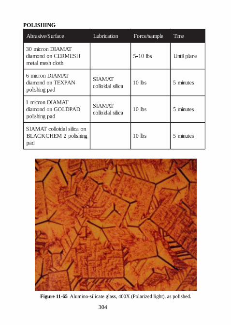
304
POLISHING
ecafruS/evisarbA noitacirbuL elpmas/ecroF emiT
TAMAIDnorcim03HSEMRECnodnomaid
htolchsemlatemsbl01-5 enalplitnU
TAMAIDnorcim6NAPXETnodnomaid
dapgnihsilop
TAMAISacilisladiolloc
sbl01 setunim5
TAMAIDnorcim1DAPDLOGnodnomaid
dapgnihsilop
TAMAISacilisladiolloc
sbl01 setunim5
noacilisladiollocTAMAISgnihsilop2MEHCKCALB
dapsbl01 setunim5
Figure 11-65 Alumino-silicate glass, 400X (Polarized light), as polished.
305
11.11.3 Mineral Specimens (Mining Concentrates)
Description:The microstructural analysis of mining concentrates or tailings is useful fordetermining if the important minerals have been liberated from the gangmaterial through grinding. In the examples shown in figures 66a and 66b, aconcentrate of chalcopyrite and molybdenite are to be separated by asecondary flotation process. For this to be effective, the chalcopyrite and themolybdenite minerals need to be separated. If they are not, an additional or anextended grinding operation may be required.
Preparation Challenge:Proper microstructural preparation of these materials must maintain thestructure of the ore concentrate.
SECTIONINGNot required
MOUNTINGCastable mounting with epoxies or acrylic resins
POLISHING
ecafruS/evisarbA noitacirbuL elpmas/ecroF emiT
repapCiStirg023 retaW sbl01-5 enalplitnU
TAMAIDnorcim6NAPXETnodnomaid
dapgnihsilop
TAMAISacilisladiolloc
sbl01 setunim5
TAMAIDnorcim1DAPDLOGnodnomaid
dapgnihsilop
TAMAISacilisladiolloc
sbl01 setunim5
noacilisladiollocTAMAIS2MEHCKCALB
dapgnihsilopsbl01 setunim5
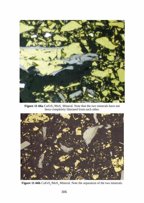
306
Figure 11-66a CuFeS2/MoS
2 Mineral. Note that the two minerals have not
been completely liberated from each other.
Figure 11-66b CuFeS2/MoS
2 Mineral. Note the separation of the two minerals.
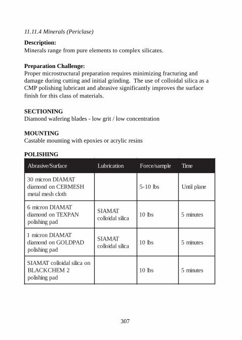
307
11.11.4 Minerals (Periclase)
Description:Minerals range from pure elements to complex silicates.
Preparation Challenge:Proper microstructural preparation requires minimizing fracturing anddamage during cutting and initial grinding. The use of colloidal silica as aCMP polishing lubricant and abrasive significantly improves the surfacefinish for this class of materials.
SECTIONINGDiamond wafering blades - low grit / low concentration
MOUNTINGCastable mounting with epoxies or acrylic resins
POLISHING
ecafruS/evisarbA noitacirbuL elpmas/ecroF emiT
TAMAIDnorcim03HSEMRECnodnomaid
htolchsemlatemsbl01-5 enalplitnU
TAMAIDnorcim6NAPXETnodnomaid
dapgnihsilop
TAMAISacilisladiolloc
sbl01 setunim5
TAMAIDnorcim1DAPDLOGnodnomaid
dapgnihsilop
TAMAISacilisladiolloc
sbl01 setunim5
noacilisladiollocTAMAIS2MEHCKCALB
dapgnihsilopsbl01 setunim5
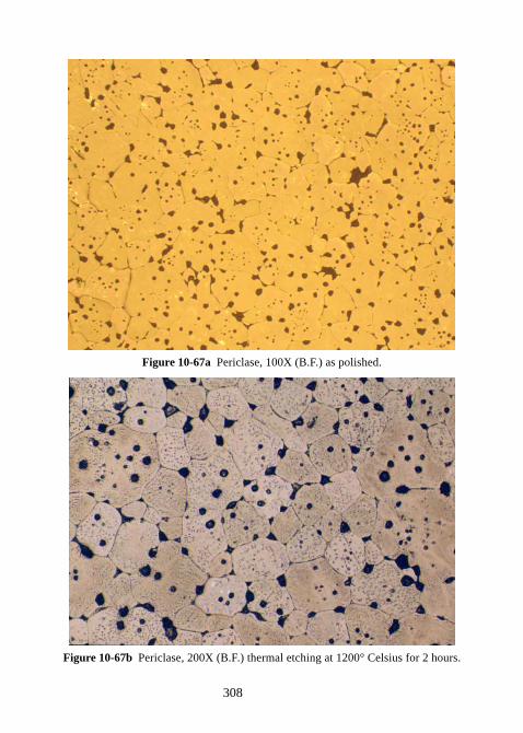
308
Figure 10-67a Periclase, 100X (B.F.) as polished.
Figure 10-67b Periclase, 200X (B.F.) thermal etching at 1200° Celsius for 2 hours.
309
APPENDIX A: REFERENCES1. G. Petzow, Metallographic Etching, ASM (American Society for Metals), 1978, p. 43.2. G. Petzow, Metallographic Etching, ASM (American Society for Metals), 1978, p. 48.3. G. Petzow, Metallographic Etching, ASM (American Society for Metals), 1978, p. 98.4. Practical Metallography, Vol. 31, No. 5, 1994, p. 229.5. G. Petzow, Metallographic Etching, ASM (American Society for Metals), 1978, p. 96.6. G. Petzow, Metallographic Etching, ASM (American Society for Metals), 1978, p. 51.7. G. Petzow, Metallographic Etching, ASM (American Society for Metals), 1978, p. 96.8. G. Petzow, Metallographic Etching, ASM (American Society for Metals), 1978, p. 61.9. Metallography, Structures and Phase Diagrams, Metals Handbook, 8th Edition, Vol. 8, ASM (American Society for Metals), Metals Park, Ohio 44079, USA, 1973, p. 132.10. G. Petzow, Metallographic Etching, ASM (American Society for Metals), 1978, p. 69.11. Metallography, Structures and Phase Diagrams, Metals Handbook, 8th Edition, Vol. 8, ASM (American Society for Metals), Metals Park, Ohio 44079, USA, 1973, p. 106.12. Metallography, Structures and Phase Diagrams, Metals Handbook, 8th Edition, Vol. 8, ASM (American Society for Metals), Metals Park, Ohio 44079, USA, 1973, pp. 101-102.13. G. Petzow, Metallographic Etching, ASM (American Society for Metals), 1978, p. 4614. G. Petzow, Metallographic Etching, ASM (American Society for Metals), 1978, p. 81.15. G. Petzow, Metallographic Etching, ASM (American Society for Metals), 1978, p. 74.16. G. Petzow, Metallographic Etching, ASM (American Society for Metals), 1978, p. 57.17. G. Petzow, Metallographic Etching, ASM (American Society for Metals), 1978, p. 94.18. G. Petzow, Metallographic Etching, ASM (American Society for Metals), 1978, p. 79.
310
19. G. Petzow, Metallographic Etching, ASM (American Society for Metals), 1978, p. 78.20. Practical Metallography, Vol. 32, No. 3, 1995, p.145.21. W. Betteridge, et.al., The Nimonic Alloys, Edward Arnold, London, 1974, p. 67.22. G. Petzow, Metallographic Etching, ASM (American Society for Metals), 1978, p. 45.23. G. Petzow, Metallographic Etching, ASM (American Society for Metals), 1978, p. 83.24. Practical Metallography, Vol. 5, No. 7, 1968, p. 378.25. G. Petzow, Metallographic Etching, ASM (American Society for Metals), 1978, p. 96.26. G. Petzow, Metallographic Etching, ASM (American Society for Metals), 1978, p. 39.27. G. Petzow, Metallographic Etching, ASM (American Society for Metals), 1978, p. 97.28. H. Modin and S. Modin, Metallurgical Microscopy, Butterworths, London, 1973, pp. 375-384.29. G. Petzow, Metallographic Etching, ASM (American Society for Metals), 1978, p. 8530. G. Petzow, Metallographic Etching, ASM (American Society for Metals), 1978, p. 88.31. 2010 Annual; Book ASTM Standards, section three “Metals Test Methods and Analytical Procedures” Vol, 03.01 Metals – Mechanical Testing; Elevated and Low-Temperature Tests; Metallography. E112-96 Standard Tests Methods for Determining Average Grain Size, ASTM International, West Conshohocken, PA, 2010, pp. 296-321.32. 2010 Annual; Book ASTM Standards, section three “Metals Test Methods and Analytical Procedures” Vol, 03.01 Metals – Mechanical Testing; Elevated and Low-Temperature Tests; Metallography. E930-99 Standard Tests Methods for Estimating the Largest Grain Observed in a Metallographic Section (ALA Grain Size), ASTM International, West Conshohocken, PA, 2010, pp. 806-810.33. 2010 Annual; Book ASTM Standards, section three “Metals Test Methods and Analytical Procedures” Vol, 03.01 Metals – Mechanical Testing; Elevated and Low-Temperature Tests; Metallography. E1181-02 Standard Tests Methods for Characterizing Duplex Grain Sizes, ASTM International, West Conshohocken, PA, 2010, pp. 861-875.34. 2010 Annual; Book ASTM Standards, section three “Metals Test Methods and Analytical Procedures” Vol, 03.01 Metals – Mechanical
311
Testing; Elevated and Low-Temperature Tests; Metallography. E1382 Standard Tests Methods for Determining Average Grain Size Using Semiautomatic and Automatic Image Analysis, ASTM International, West Conshohocken, PA, 2010, pp. 979-1000.35. 2010 Annual; Book ASTM Standards, section three “Metals Test Methods and Analytical Procedures” Vol, 03.01 Metals – Mechanical Testing; Elevated and Low-Temperature Tests; Metallography. E562 Standard Test Method for determining volume Fraction by Systematic Manaul Point Count, ASTM International, West Conshohocken, PA, 2010, pp. 629-635.36. 2010 Annual; Book ASTM Standards, section three “Metals Test Methods and Analytical Procedures” Vol, 03.01 Metals – Mechanical Testing; Elevated and Low-Temperature Tests; Metallography. E1245-03 Standard Practice for Determining the Inclusion or Second-Phase Constituent Content of Metals by Automatic Image Analysis, ASTM International, West Conshohocken, PA, 2010, pp. 899-906.37. 2010 Annual Book of ASTM Standards, Section 2, Nonferrous Metal Products, Volume 02.05, Metallic and Inorganic Coatings; Metal Powders and Metal Powder Products. A247 -06 Standard Test Method for Evaluating the Microstructure of Graphite in Iron Castings, ASTM International, West Conshohocken, PA, 2010, pp. 112-113.38. 2010 Annual Book of ASTM Standards, Section 2, Nonferrous Metal Products, Volume 02.05, Metallic and Inorganic Coatings; Metal Powders and Metal Powder Products. E45 Standard Test Method for Determining the Inclusion Content of Steel, ASTM International, West Conshohocken, PA, 2010, pp. 207-225.39. 2010 Annual Book of ASTM Standards, Section 2, Nonferrous Metal Products, Volume 02.05, Metallic and Inorganic Coatings; Metal Powders and Metal Powder Products. E1077 Standard Test Methods for Estimating the Depth of Decarbuization of Steel Specimens, ASTM International, WestConshohocken, PA, 2010, pp. 847-856.40. 2010 Annual Book of ASTM Standards, Section 2, Nonferrous Metal Products, Volume 02.05, Metallic and Inorganic Coatings; Metal Powders and Metal Powder Products. B487-85 Standard Test Method for Measurement of Metal and Oxide Coating Thickness by Microscopical Examination of Cross Section, ASTM International, West Conshohocken, PA, 2010, pp. 222-223.
312
31. G. Vander Voort, Metallography Principles and Practice; McGraw-Hill, New York, 1984, p. 610.32.G. Vander Voort, Metallography Principles and Practice; McGraw-Hill, New York, 1984, p. 611.33. G. Petzow, Metallographic Etching, ASM (American Society for Metals), 1978, p. 60.34. Metals Handbook Ninth Edition; American Society for Metals, Metals Park, OH, 1985, pp. 354-355.35. Metals Handbook Ninth Edition; American Society for Metals, Metals Park, OH, 1985, pp. 352-354.36. Metals Handbook Ninth Edition; American Society for Metals, Metals Park, OH, 1985, p. 399.37. G. Petzow, Metallographic Etching, ASM (American Society for Metals), 1978, p. 58.38. G. Petzow, Metallographic Etching, ASM (American Society for Metals), 1978, p. 60.39. G. Petzow, Metallographic Etching, ASM (American Society for Metals), 1978, p. 61.40. G. Vander Voort, Metallography Principles and Practice; McGraw-Hill, New York, 1984, p. 625.41. G. Vander Voort, Metallography Principles and Practice; McGraw-Hill, New York, 1984, p. 691.42. C.J. Thwaites, M.E. Warwick and Brian Scott, Metals Handbook Ninth Edition; American Society for Metals, Metals Park, OH, 1985, p. 450.43. Gunter Petzow, Metallographic Etching, American Society of Metals; Metals Park, OH, 1978, p. 84.44. Gunter Petzow, Metallographic Etching, American Society of Metals; Metals Park, OH, 1978, p. 80.45. Carl DiMartini, Metals Handbook Ninth Edition; American Society for Metals, Metals Park, OH, 1985, p. 415.46. G. Vander Voort, Metallography Principles and Practice; McGraw-Hill, New York, 1984, p. 656.47. C.J. Thwaites, M.E. Warwick and Brian Scott, Metals Handbook NinthEdition; American Society for Metals, Metals Park, OH, 1985, p. 450.48. Gunter Petzow, Metallographic Etching, American Society of Metals; Metals Park, OH, 1978, p. 84.49. G. Vander Voort, Metallography Principles and Practice; McGraw-Hill, New York, 1984, p. 700.50. Metals Handbook Ninth Edition; American Society for Metals, Metals Park, OH, 1985, p. 488.
313
51. Gunter Petzow, Metallographic Etching, American Society of Metals; Metals Park, OH, 1978, p. 88.52. Gunter Petzow, Metallographic Etching, American Society of Metals; Metals Park, OH, 1978, p. 54.53. John Lambert and Mortimer Schussler, Metals Handbook Ninth Edition; American Society for Metals, Metals Park, OH, 1985, p. 440.54. Petzow, Metallographic Etching, ASM (American Society for Metals), 1978, p. 56.55. G. Vander Voort, Metallography Principles and Practice; McGraw-Hill, New York, 1984, pp. 679-681.56. G. Petzow, Metallographic Etching, ASM (American Society for Metals), 1978, p. 55.57. G. Petzow, Metallographic Etching, ASM (American Society for Metals), 1978, p. 39.58. Gunter Petzow, Metallographic Etching, American Society of Metals; Metals Park, OH, 1978, p. 37.59. G. Petzow, Metallographic Etching, ASM (American Society for Metals), 1978, p. 38.60. Petzow, Metallographic Etching, ASM (American Society for Metals), 1978, p. 45.61. G. Vander Voort, Metallography Principles and Practice; McGraw-Hill, New York, 1984, p. 629.62. G. Petzow, Metallographic Etching, ASM (American Society for Metals), 1978, p. 64.63. E. Beraha and B. Sphigler, Color Metallography, American Society for Metals (ASM), Metals Park, Ohio 40073, USA, 1977, p. 37.64. G. Petzow, Metallographic Etching, ASM (American Society for Metals), 1978, p. 64.65. G. Vander Voort, Metallography Principles and Practice; McGraw-Hill, New York, 1984, p. 644.66. Metals Handbook Ninth Edition; American Society for Metals, Metals Park, OH, 1985, p. 532.67.G. Vander Voort, Metallography Principles and Practice; McGraw-Hill, New York, 1984, p. 643.68. G. Vander Voort, Metallography Principles and Practice; McGraw-Hill, New York, 1984, p. 646.69. G. Vander Voort, Metallography Principles and Practice; McGraw-Hill, New York, 1984, p. 632.70. E. Beraha and B. Sphigler, Color Metallography, American Society for Metals (ASM), Metals Park, Ohio 40073, USA, 1977, p. 47.
314
71. George Vander Voort, Metals Handbook Ninth Edition; American Society for Metals, Metals Park, OH, 1985, p. 257.72. George Vander Voort and Hughston James, Metals Handbook Ninth Edition; American Society for Metals, Metals Park, OH, 1985, p. 281.73. G. Vander Voort, Metallography Principles and Practice; McGraw-Hill, New York, 1984, p. 620.74. George Vander Voort, Metals Handbook Ninth Edition; American Society for Metals, Metals Park, OH, 1985, p. 308.75. George Vander Voort and Hughston James, Metals Handbook Ninth Edition; American Society for Metals, Metals Park, OH, 1985, p. 306.76. George Vander Voort, Metals Handbook Ninth Edition; American Society for Metals, Metals Park, OH, 1985, p. 308.77. G. Vander Voort, Metallography Principles and Practice; McGraw-Hill, New York, 1984, p. 666.78. Gunter Petzow, Metallographic Etching, American Society of Metals; Metals Park, OH, 1978, p. 76.79. G. Vander Voort, Metallography Principles and Practice; McGraw-Hill, New York, 1984, p. 692.80. Rodney Boyer, Metals Handbook Ninth Edition; American Society for Metals, Metals Park, OH, 1985, p. 458.81. G. Vander Voort, Metallography Principles and Practice; McGraw-Hill, New York, 1984, pp. 693-694.82. Rodney Boyer, Metals Handbook Ninth Edition; American Society for Metals, Metals Park, OH, 1985, p. 458.83. Gunter Petzow, Metallographic Etching, American Society of Metals; Metals Park, OH, 1978, p. 86.84. Rodney Boyer, Metals Handbook Ninth Edition; American Society for Metals, Metals Park, OH, 1985, p. 458.85. Gunter Petzow, Metallographic Etching, American Society of Metals; Metals Park, OH, 1978, p. 86.86. George Vander Voort, Metals Handbook Ninth Edition; American Society for Metals, Metals Park, OH, 1985, p. 257.87. Gunter Petzow, Metallographic Etching, American Society of Metals; Metals Park, OH, 1978, pp. 92-98.88. Metals Handbook, 9th Edition “Metallography and Microstructures,” American Society for Metals; Metals Park, OH, 1985, pp. 67-69.89. Gunter Petzow, Metallographic Etching. American Society for Metals; Metals Park, OH 44073, 1976, pp. 103-104.
315
APPENDIX B: SAFETYPROCEDURES
B.1 STORAGE
- Clearly label all containers
- HF, H2SiF
6 and HBF
4 storage – these materials react with glass, therefore
proper storage should be in polyethylene, polypropylene or similarly inertplastic containers (88).
- Strong alkaline solutions – these materials react with glass, therefore properstorage should be in polyethylene, polypropylene or similarly inert plasticcontainers (88).
- Phosphoric acid (H3PO
4) – these materials react with glass, therefore proper
storage should be in polyethylene, polypropylene or similarly inert plasticcontainers (88).
- Perchloric acid (HClO4) – do not store high concentration of perchloric acid
in plastic bottles (89).
B.2 DANGEROUS MIXTURES
Review all Material Safety Data Sheets (MSDS) before mixing
- Perchloric acid in concentrations exceeding 60% are highlyFLAMMABLE and EXPLOSIVE. The danger is greatly increased by thepresence of organic materials or metals that oxidize readily. Keeptemperature of the solution below 35°C (95°F) and, if necessary, use a coolantbath. Safety glasses are helpful; however, a safety shield is preferable.
- Nital (methanol/ethanol and HNO3) can build up a gaseous reaction product
and must be stored in a vented or pressure-relief container (88).
- Mixtures of alcohol and hydrochloric acid can react in various ways toproduce aldehydes, fatty acids, explosive nitrogen compounds, etc. Thelikelihood of EXPLOSION increases with increasing molecule size.Hydrochloric acid content should not exceed 5% in ethanol or 35% inmethanol. These mixtures should not be stored (89).
316
- Mixtures of phosphoric acid can result in the formation of ester, some ofwhich are potent nerve POISONS. If absorbed through the skin or inhaled,severe personal injury may result (89).
- Mixtures of methanol and sulfuric acid may form dimethylene sulfate, anodorless, tasteless compound that may be FATAL if absorbed in sufficientquantities into the skin or respiratory tract. Even gas masks do not offeradequate protection. Sulfates of the higher alcohols, however, are notpotentially dangerous poisons (89).
- Mixtures of chromium (VI) oxide and organic materials are EXPLOSIVE.Mix with care and do not store (89).
- Lead and lead salts are highly TOXIC, and the damage produced iscumulative. Care is also recommended when handling cadmium, thallium,nickel, mercury, and other heavy metals (89) to avoid toxicity.
- Cyanide compounds (CN) are highly dangerous because hydrocyanic acid(HCN) may easily form. These are fast-acting POISONS that can causeDEATH, even in relatively low concentrations.
- Hydrofluoric acid is a very strong skin and respiratory POISON that is hardto control. It should be handled with extreme care, because sores resultingfrom its attack on the skin do not readily heal. Hydrofluoric acid also attacksglass, and fumes from specimens etched in HF solution could easily damagefront elements of microscope lenses. Specimens should be rinsed thoroughlyand in some cases, placed in a vacuum desiccator for one to two hours beforeexamination.
- Picric acid anhydride is an EXPLOSIVE.
- Mixing oxidizing agents with reducing agents. Mixing oxidizing agents,such as HNO
3, H
3SO
4, perchloric acid (HClO
4), CrO
3, salts of these acids,
persulfates, Br2 and H
2O
2, with reducing agents – for example, alcohols and
other organic solvents, acetic acid, acetic anhydride and most organiccompounds – requires special care (88). Mix slowly and stir continuously.

317
B.3 PERSONAL SAFETY
- Wear appropriate eye protection (safety goggles or safety glasses – seeMSDS sheets).
- Wear approved rubber gloves and laboratory coats or aprons.
- Mix etchant and etch with adequate and appropriate ventilation. A fumehood is generally recommended.
- FIRST AID – Review MSDS sheets for specific medical instructions.
SKIN – In case of contact, immediately flush skin with plenty of waterfor at least 15 minutes while removing contaminated clothing and shoes.Get medical attention immediately. Wash clothing before reuse.Thoroughly clean shoes before reuse.
EYES – Immediately flush eyes with plenty of water for at least 15minutes, lifting lower and upper eyelids occasionally. Get medicalattention immediately.
INHALATION – Remove to fresh air immediately. If not breathing, giveartificial respiration. If breathing is difficult, give oxygen. Get medicalattention immediately.
INGESTION: Refer to MSDS sheets for specific guidelines. Never giveanything by mouth to an unconscious person. Get medical attentionimmediately.
B.4 MIXING GUIDELINES
- Acids and Bases: ALWAYS mix concentrated acids and bases into water toprevent excessive heat generation.
- Monitor temperature of mixture to prevent overheating.
- Mix in well ventilated area.
- Use recommended personal safety equipment.
318
B.5 DISPOSAL
When appropriate, dilute all concentrated chemicals prior to disposal. Ifregulations allow disposal to sewer, use a substantial amount of running waterand slowly add etchant to flow. Continue to purge drain thoroughly withwater. Follow all Local, State and Federal Disposal Guidelines.
B.6 DISCLAIMER
THE INFORMATION AND RECOMMENDATIONS SET FORTH HEREINARE TAKEN FROM SOURCES BELIEVED TO BE ACCURATE AS OFTHE DATE HEREIN: HOWEVER, PACE TECHNOLOGIES MAKES NOWARRANTY, EXPRESS OR IMPLIED WITH RESPECT TO THEACCURACY OF THE INFORMATION OR THE SUITABILITY OF THERECOMMENDATIONS, AND ASSUMES NO LIABILITY TO ANY USERTHEREOF.

319

320

321

322

323

324

325

326

327
328
Index
A
Abrasive cutting fluid 30ABRASIVE GRINDING 84
ABRASIVE BONDING 75Fixed Abrasive Grinding 75, 76Free Abrasive Grinding 76Semi-fixed Abrasive Grinding 76
GRINDING ABRASIVES 64Alumina 71Silicon Carbide 65, 66Zirconia 75
LAPPING FILMS 85Alumina 87Diamond 87Silicon Carbide 86TROUBLESHOOTING 88
ROUGH GRINDING PARAMETERS 78, 84Ceramics 84Relative Velocity 79Soft ferrous metals 83Soft nonferrous metals 83
ROUGH POLISHINGAutomated rough polishing 92Chemical Mechanical Polishing 92Rough polishing abrasives 89Rough polishing pads 89
ABRASIVE SECTIONING 26, 27Alumina 27, 29CUTTING FLUIDS 30MEGACUT-M300 Abrasive Cutter 32RECOMMENDED CUTTING PROCEDURES 30Resin abrasive blades 27, 29Resin rubber abrasive blades 27, 29
329
Silicon carbide 27, 29TROUBLESHOOTING 31
Acrylics 41, 54, 57, 58Alloy steel 222Alumina 27, 29, 71, 87, 98, 103Alumina ceramic 234, 280, 283, 284, 294Alumino-Silicate glass 303, 304Aluminum 13, 14, 174, 175, 176, 177Aluminum Nitride 15, 139, 140, 234, 235Amyl nital etchant 243Anodized Aluminum 10, 175Aqua regia 252ASTM Standards 142
A247 - Nodularity 142, 148B487 - Coating Thickness 142, 161E1077 - Decarburization 142, 158E112 - Grain Size 142E1181 - Grain size 142, 143E1245 - Inclusions 142, 146E1245 - Porosity 142, 146, 153E1382 - Grain Size 142, 143E45 - Inclusions 142, 156E562 - Porosity 142, 146, 153E930 - Grain Size 142, 143
ATLANTIS Polishing Pad 101Attack polish 107, 258
B
B4C-graphite composite 11BaCl 11Bainite 223, 241, 242, 243, 272, 273Barium titanate 225, 226, 295Beraha's etch 180, 182, 222, 253, 261Beryllia 231, 233, 234, 235, 294Beryllium 125, 126, 127, 129, 130, 131BLACK Chem 2 polishing pad 106Boride ceramics 126, 127, 129, 130, 131, 280, 290Boron carbide 126, 127, 129, 130, 131, 181, 308Brass 10, 125, 173, 176, 182, 183
330
Brightfield Illumination 137, 138Bronze 176, 182, 185, 186Buchheit's reagent 205
C
Cadmium 126, 127, 129, 130, 131Calcined alumina 98, 103Carbide ceramics 126, 127, 129, 130, 131, 291Carbides 291Carbon fiber composite 19Carbon-Carbon Composite 198Carburized 9, 22Cast iron 20, 148, 215, 219, 222, 223Castable Mounting 41, 47
Acrylics 41, 42, 45Epoxy Resins 41, 42, 44Polyesters 41, 42, 46TROUBLESHOOTING 51Vacuum/Pressure Mounting 48
CBN. See Cubic Boron NitrideCementite 222, 242, 273Ceramic matrix composites 280, 296, 298
Hafnium Diboride in a Boron Nitride Matrix 298SiC fibers in a Silicon Nitride (5% mullite) matri 297SiC particles in a Si3N4 matrix 299
Ceramics 84CERMESH metal mesh cloth 77Chemical etching 133Chemical Mechanical Polishing
Colloidal silica abrasives 94, 96Chemical Mechanical Polishing (CMP) 92Chromium 205CMC. See Ceramic matrix compositesCMP 92. See Chemical Mechanical PolishingCoating thickness 9, 15, 142
ASTM B487 142, 161Cobalt 126, 211, 248, 251, 252Cold pressed metal 12Colloidal silica 96, 104, 105
331
Complimentary grinding 79Composites 19, 84COMPRESSION MOUNTING 55, 57
Acrylics 57, 58Conductive Resins 54Diallyl Phthalate 54, 57, 60Epoxy Resins 54, 57Phenolic Resins 54, 57, 58
COMPRESSION MOUNTING RESIN PROPERTIES 55Conductive Mounting Resins 54Contra grinding 79Copper
11, 12, 125, 126, 173, 176, 177, 178, 179, 180, 181, 182, 185, 187, 188, 191, 192, 308Corrosion 9, 13Cracks 9, 11Cubic Boron Nitride 27, 33Cutting Fluids 30
Abrasive Cutting 30
D
DACRON polishing pad 91Darkfield Illumination 137Decarburization 9, 23, 142
ASTM E1077 142, 158Defects
Comet Tails 115Edge Rounding 117Embedded Abrasives 116Gaps and Staining 120Polishing Relief 118Porosity and cracks 121Pull-out 119Recrystallization 114Scratches 112Smearing 113
Dendritic growth 9, 13Depth of Field 137Diallyl Phthalate 54, 57Diamond 27, 33, 35
332
Differential Interference Contrast Illumination 140Ductile Cast Iron 20Dysprosium 208
E
Electrolyte Solutions 125ELECTROLYTIC ETCHING 133ELECTROLYTIC POLISHING 107
Electrolyte Solutions 125Perchloric acid (HClO4) electrolyte precautions 123Polishing Equipment 124Safety Precautions 123
Electronic Die Packages 227Empty Magnification 137Engineered Ceramics 280Epoxy Resins 41, 42, 44, 54, 57, 60Erbium 208Etch-polishing 107ETCHING 132, 133
CHEMICAL ETCHING 133ELECTROLYTIC ETCHING 133MOTLEN SALT ETCHING 134THERMAL ETCHING 134
F
Ferrite 222, 223, 241, 242, 243, 272, 273Ferrite magnets 224, 238FINAL POLISHING 97
FINAL POLISHING ABRASIVES 98Colloidal silica 104Polycrystalline Alumina 101
G
GaAs 224Gadalinium 208Gallauger etch 260Garnets etchant 238Gelles reagent 196Gennone and Kersely reagent 196
333
Germanium 125Glass etchants 294Glass-Ceramics 303Glyceregias etch 253Goerens' amyl picral 243Gold 201, 212, 214GOLDPAD polishing pad 91Graff and Sargent reagent 176Grain size 9, 10, 142
ASTM E112 142ASTM E1181 142ASTM E1382 142ASTM E930 142
Graphite nodularity 9, 20Graphite-polymer composite 12Gray Cast Iron 20, 219Greosbeck's reagent 273Gurevich etch 261
H
Hafnium boride 290Hard ferrous metals 83HARDNESS 165, 166, 168
Brinell 166, 167Microhardness 165, 166
Knoop 169Vickers 169
Rockwell 166Vickers 166
Heat Affected Zone (HAZ) 9, 17Hergert and Altenhoff reagent 208Holmium 208
I
Image Analysis 140Stereology 140
Inclusion 9, 16, 142, 146ASTM E1245 142ASTM E45 142, 156
334
JK-type inclusion rating 156Inconel 127, 248Intergranular attack (IGA) 9, 14Intergranular fracture 24Iridium 130, 131Iron 12, 242Iron-nickel alloys 253, 254
J
Jeffries Procedure 142JK-type inclusion rating 156
K
Kalling's reagent 253Keller's reagent 176, 260Klemm's reagent 182, 196, 223Knoop Hardness 169Kroll's reagent 260
L
Lapping Films 85, 86, 87Alumina 87
Lead 173, 191, 193Lepito's No. 1 etch 247Levigated Alumina 98Lundin and Klodt reagent 208
M
M6 Tool steel 273Magnetic Alloys (Ferrite Ceramics) 236, 238Manganese-Aluminum Bronze 186Marbles's reagent 247, 252Martensite 223, 242, 272MEGA-M300 Abrasive Saw. 32MEMS Devices 230, 231Metal Matrix Composites 258, 275, 278
SiC particles in an Aluminum Matrix 277ZrB2 particles in a Titanium Matrix, 276
335
Metallographic Specimen Preparation 170, 239CLASS 1 - Ductile Materials 173CLASS 10 - Engineered Ceramics 280CLASS 11 - Very Hard Brittle Materials 300CLASS 2 - Very Soft, Low ductility Materials 201CLASS 3 - Lower Ductility Metals 215CLASS 4 - Soft, Brittle Nonmetals (Electronics) 224CLASS 6 - Tough, Hard Non-Ferrous Metals 248CLASS 7 - Thermal Spray Materials 263CLASS 8 - Hardened Steels 267CLASS 9 - Metal Matrix Composites 274
Microhardness 165MICROPAD 2 Polishing pad 101MICROPAD Polishing pad 101MICROSCOPY 136, 137
Brightfield Illumination 138Darkfield Illumination 139Differential Interference Contrast Illumination 140Empty Magnification 137Optical filters 138Resolution 137Working Distance 137
Mineral Specimens 305CuFeS2/MoS2 Mineral 306Periclase 307, 308
MOLTEC 2 polishing pad 103Molybdenum 127, 201, 204, 211Monel 125Monocrystalline diamond 72, 74MOTLEN SALT ETCHING 134Mounting 41
Castable Mounting. See Castable MountingCompression Mounting. See Compression Mounting.
Mullite ceramic 280Multilayer Ceramic Capacitors 225Murakami's reagent 205, 211, 242, 245, 252, 273Myklebust and Daane reagent 208
336
N
NAPPAD Polishing pad 101Ni-Fe-Al bronze 12Ni-Zn ferrite 237Nickel 14, 127, 248, 251, 253Nickel Chrome Thermal Spray Coating 266Nickel-Iron Bronze 186Nimonic 127, 250, 251NiO 127Niobium 127, 201, 202, 203, 204Nital etchant 222, 241, 242, 272Nitride Ceramics 292, 293Nitrides 292, 293Nitriding 9, 23, 270, 271nodular cast iron 148Nodularity 9, 20, 142, 148, 219
ASTM A247 142Numerical Aperture (N.A.) 137NYPAD polishing pad 91
O
Ogden and Holden etch 261Optical microscopy 136Osmium 130, 131Oxide Ceramics 294, 295Oxides 294, 295
P
Palladium 130, 131, 214Palmerton's reagent 196, 197Pearlite 223, 241, 242, 243, 273Periclase 308Phase 9, 12Phase analysis 142, 146
ASTM E1245 142ASTM E562 142
Phenolic Resins 54, 57, 58PICO 150 Precision Wafering Saw 32, 33
337
Picral etchant 223, 242, 272Plasma spray 15Platinum 201, 212, 214Plutonium 130, 131PMC. See Polymer matrix compositesPolishing Defects
Scratches 112Polishing Pads
ATLANTIS Polishing pad 101, 102BLACK Chem 2 Polishing pad 106CERMESH Metal Mesh cloth 77DACRON Polishing pad 91GOLDPAD Polishing pad 91MICROPAD 2 Polishing pad 101, 104, 106MICROPAD Polishing pad 101NAPPAD Polishing pad 101, 103NYPAD Polishing pad 91POLYPAD Polishing pad 90TEXPAN Polishing pad 90, 106TRICOTE Polishing pad 101, 102
Polycrystalline Alumina 98, 103Polycrystalline Diamond 72, 73, 74Polyesters 41, 46Polymer matrix composites 173Polymers 173POLYPAD polishing pad 90Porosity 9, 11, 142, 153
ASTM 562 142Pourbaix diagrams 93, 132Precious Metals 212Precision Wafer Sectioning. See WAFER SECTIONINGPRESTON’S LAW 78PZT 224
R
R-etch 260Rate Earth elements 208Recast 9, 21Refractory metals 202
338
Resin abrasive blades. See ABRASIVE SECTIONINGResin rubber abrasive blades. See ABRASIVE SECTIONINGRhenium 10, 201, 202, 203, 205Rosen and Sprang reagent 208
S
Scandium 208Sensitization 14, 24SiAlON 134, 282SIAMAT colloidal silica 104, 105SiC etch 291SiC particles in an Aluminum Matrix 277Silicon carbide 27, 29, 65, 66, 130, 131
Lapping films 86Silicon carbide ceramic 280Silicon nitride 94, 281, 292, 293Silver 130, 131, 201, 212, 213Sintered iron 217SiSiC 280, 288, 289Slag 301, 302Smith etch 260Soft ferrous metals 83Soft nonferrous metals 83Solder 19, 173, 182Stainless steel 179, 247
300 Series 246400 Series 245
Steel 239, 242, 243Stereology 140Superalloys 125, 248, 249, 252, 253, 254Superpicral 243, 272
T
TEXPAN polishing pad 90THERMAL ETCHING 134Thermal Spray coatings 263, 265three body abrasive 76Tin 173, 187, 189, 190Titanium 255, 256, 257, 258, 259, 260, 261, 262, 279
339
Cast 256Wrought 257
Titanium boride 290Titanium carbide 126, 127, 129, 130, 131, 279Titanium nitride 292Tool steel 242, 268, 269, 270, 272, 273Tough Pitch Copper 179, 180, 188, 192TRICOTE Polishing pad 101Tungsten 201, 202, 204, 211Twin Boundaries 10two body abrasive 75Type metal 192
V
Vacuum/Pressure Mounting 48Vanadium 204Vibratory polishing 108Vilella's reagent 176, 243, 272, 273Voids 9, 11
W
WAFER SECTIONING 32, 39CBN 27, 33Diamond 27, 33, 35Dressing 37Guidelines 39PICO 150 Precision Wafering Saw 33
Weck's etch 261Weld 9, 17
Weld analysis 142, 163Weld Sensitization 24White Iron 220, 221Working Distance 137
Y
Yttrium 208

340
Z
Zinc 173, 177, 196, 197Zinc-Aluminum alloy 195Zirconia 75Zirconium boride 290ZRO2 Ceramic 135, 280, 281, 282, 295

341

342

343