Embed Size (px)
Citation preview
PATENTS
12Sealing Technology January 2013
question, was not sufficient to properly identify the leak source. Next, the team deployed a general-purpose acoustic measuring device to identify the leak, but because all three trains
had high background noise/interference this technique also failed.
The Midas Meter was finally deployed, fol-lowing the owner’s recommendation. Despite
the extremely high background noise and tur-bulence around the valves the instrument was able to conclusively identify two leaking valves on one train, enabling them to be targeted for maintenance.
If the Midas Meter had been a part of the initial plant troubleshooting plans its use would have saved the customer a great deal of time and effort, leading to significant cost savings in recurring remedial repair work and plant down-time. Based on its positive experience the customer proceeded to purchase one.
Contacts:
Score (Europe) Ltd, Glenugie Engineering Works,
Peterhead, Aberdeenshire AB42 0YX, Scotland, UK.
Tel: +44 1779 480 000,
Fax: +44 1779 481 100,
www.midasmeter.com
Score Atlanta Inc, 975 Cobb Place Boulevard,
Suite 202, Kennesaw, GA 30144, USA.
Tel: +1 770 428 4874,
Fax: +1 770 428 4845
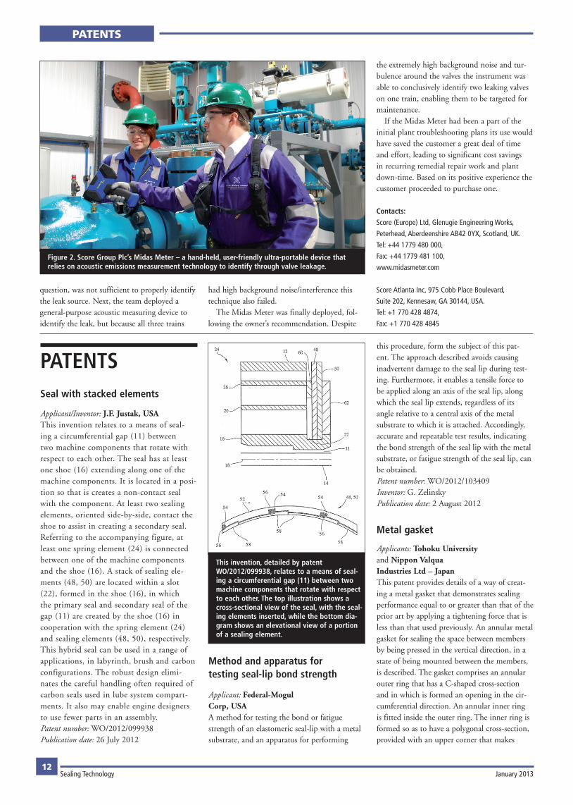
Figure 2. Score Group Plc’s Midas Meter – a hand-held, user-friendly ultra-portable device that relies on acoustic emissions measurement technology to identify through valve leakage.
PATENTSSeal with stacked elements
Applicant/Inventor: J.F. Justak, USAThis invention relates to a means of seal-ing a circumferential gap (11) between two machine components that rotate with respect to each other. The seal has at least one shoe (16) extending along one of the machine components. It is located in a posi-tion so that is creates a non-contact seal with the component. At least two sealing elements, oriented side-by-side, contact the shoe to assist in creating a secondary seal. Referring to the accompanying figure, at least one spring element (24) is connected between one of the machine components and the shoe (16). A stack of sealing ele-ments (48, 50) are located within a slot (22), formed in the shoe (16), in which the primary seal and secondary seal of the gap (11) are created by the shoe (16) in cooperation with the spring element (24) and sealing elements (48, 50), respectively. This hybrid seal can be used in a range of applications, in labyrinth, brush and carbon configurations. The robust design elimi-nates the careful handling often required of carbon seals used in lube system compart-ments. It also may enable engine designers to use fewer parts in an assembly.Patent number: WO/2012/099938Publication date: 26 July 2012
Method and apparatus for testing seal-lip bond strength
Applicant: Federal-Mogul Corp, USAA method for testing the bond or fatigue strength of an elastomeric seal-lip with a metal substrate, and an apparatus for performing
this procedure, form the subject of this pat-ent. The approach described avoids causing inadvertent damage to the seal lip during test-ing. Furthermore, it enables a tensile force to be applied along an axis of the seal lip, along which the seal lip extends, regardless of its angle relative to a central axis of the metal substrate to which it is attached. Accordingly, accurate and repeatable test results, indicating the bond strength of the seal lip with the metal substrate, or fatigue strength of the seal lip, can be obtained.Patent number: WO/2012/103409Inventor: G. ZelinskyPublication date: 2 August 2012
Metal gasket
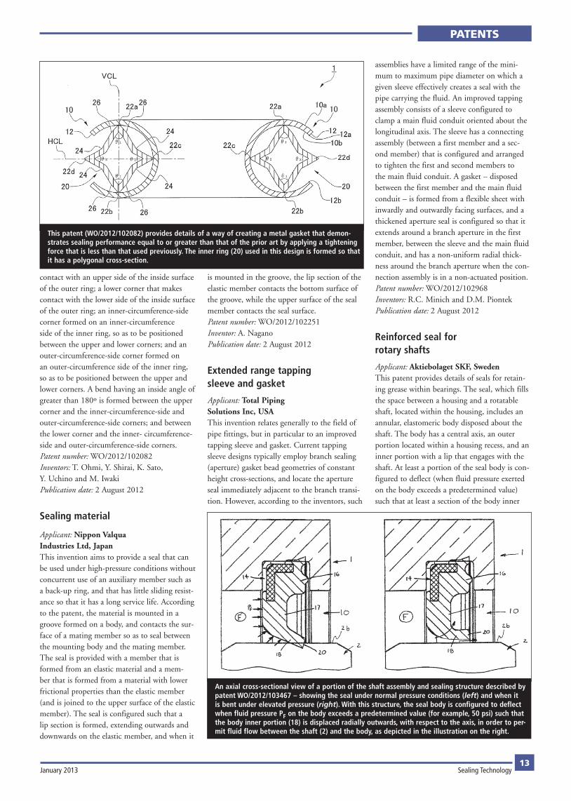
Applicants: Tohoku University and Nippon Valqua Industries Ltd – JapanThis patent provides details of a way of creat-ing a metal gasket that demonstrates sealing performance equal to or greater than that of the prior art by applying a tightening force that is less than that used previously. An annular metal gasket for sealing the space between members by being pressed in the vertical direction, in a state of being mounted between the members, is described. The gasket comprises an annular outer ring that has a C-shaped cross-section and in which is formed an opening in the cir-cumferential direction. An annular inner ring is fitted inside the outer ring. The inner ring is formed so as to have a polygonal cross-section, provided with an upper corner that makes
This invention, detailed by patent WO/2012/099938, relates to a means of seal-ing a circumferential gap (11) between two machine components that rotate with respect to each other. The top illustration shows a cross-sectional view of the seal, with the seal-ing elements inserted, while the bottom dia-gram shows an elevational view of a portion of a sealing element.
PATENTS
January 2013 Sealing Technology13
contact with an upper side of the inside surface of the outer ring; a lower corner that makes contact with the lower side of the inside surface of the outer ring; an inner-circumference-side corner formed on an inner-circumference side of the inner ring, so as to be positioned between the upper and lower corners; and an outer-circumference-side corner formed on an outer-circumference side of the inner ring, so as to be positioned between the upper and lower corners. A bend having an inside angle of greater than 180º is formed between the upper corner and the inner-circumference-side and outer-circumference-side corners; and between the lower corner and the inner- circumference-side and outer-circumference-side corners.Patent number: WO/2012/102082Inventors: T. Ohmi, Y. Shirai, K. Sato, Y. Uchino and M. IwakiPublication date: 2 August 2012
Sealing material
Applicant: Nippon Valqua Industries Ltd, JapanThis invention aims to provide a seal that can be used under high-pressure conditions without concurrent use of an auxiliary member such as a back-up ring, and that has little sliding resist-ance so that it has a long service life. According to the patent, the material is mounted in a groove formed on a body, and contacts the sur-face of a mating member so as to seal between the mounting body and the mating member. The seal is provided with a member that is formed from an elastic material and a mem-ber that is formed from a material with lower frictional properties than the elastic member (and is joined to the upper surface of the elastic member). The seal is configured such that a lip section is formed, extending outwards and downwards on the elastic member, and when it
is mounted in the groove, the lip section of the elastic member contacts the bottom surface of the groove, while the upper surface of the seal member contacts the seal surface.Patent number: WO/2012/102251Inventor: A. NaganoPublication date: 2 August 2012
Extended range tapping sleeve and gasket
Applicant: Total Piping Solutions Inc, USAThis invention relates generally to the field of pipe fittings, but in particular to an improved tapping sleeve and gasket. Current tapping sleeve designs typically employ branch sealing (aperture) gasket bead geometries of constant height cross-sections, and locate the aperture seal immediately adjacent to the branch transi-tion. However, according to the inventors, such
assemblies have a limited range of the mini-mum to maximum pipe diameter on which a given sleeve effectively creates a seal with the pipe carrying the fluid. An improved tapping assembly consists of a sleeve configured to clamp a main fluid conduit oriented about the longitudinal axis. The sleeve has a connecting assembly (between a first member and a sec-ond member) that is configured and arranged to tighten the first and second members to the main fluid conduit. A gasket – disposed between the first member and the main fluid conduit – is formed from a flexible sheet with inwardly and outwardly facing surfaces, and a thickened aperture seal is configured so that it extends around a branch aperture in the first member, between the sleeve and the main fluid conduit, and has a non-uniform radial thick-ness around the branch aperture when the con-nection assembly is in a non-actuated position.Patent number: WO/2012/102968Inventors: R.C. Minich and D.M. PiontekPublication date: 2 August 2012
Reinforced seal for rotary shafts
Applicant: Aktiebolaget SKF, SwedenThis patent provides details of seals for retain-ing grease within bearings. The seal, which fills the space between a housing and a rotatable shaft, located within the housing, includes an annular, elastomeric body disposed about the shaft. The body has a central axis, an outer portion located within a housing recess, and an inner portion with a lip that engages with the shaft. At least a portion of the seal body is con-figured to deflect (when fluid pressure exerted on the body exceeds a predetermined value) such that at least a section of the body inner
This patent (WO/2012/102082) provides details of a way of creating a metal gasket that demon-strates sealing performance equal to or greater than that of the prior art by applying a tightening force that is less than that used previously. The inner ring (20) used in this design is formed so that it has a polygonal cross-section.
An axial cross-sectional view of a portion of the shaft assembly and sealing structure described by patent WO/2012/103467 – showing the seal under normal pressure conditions (left) and when it is bent under elevated pressure (right). With this structure, the seal body is configured to deflect when fluid pressure PF on the body exceeds a predetermined value (for example, 50 psi) such that the body inner portion (18) is displaced radially outwards, with respect to the axis, in order to per-mit fluid flow between the shaft (2) and the body, as depicted in the illustration on the right.