Embed Size (px)
Citation preview
Mesoscopic Network Representation Protocols for Model Handling
October 2016 | Version: 1

Mesoscopic Network Representation: Protocols for Model Handling – October 2016 2
Glossary of Terms Term/Abbreviation Description
Base Model Development Report A model calibration/validation report, as described in the Traffic Modelling Guidelines (RMS, 2013)
BMDR Base Model Development Report - As described in RMS Traffic Modelling Guidelines (2013) i.e. calibration/validation report
GIS Geographical Information System
GMA Greater Metropolitan Area
GTFS General Transit Feed Specification
GUID Global Unique Identifier
Incoming Network Representation Protocols (INRP)
A process that industry should follow to ensure consistency is maintained in Sydney Aimsun Foundation Model (SAFN). INRP consists of three distinct streams: auditing/checking, model modifications and sign off
LPI Land & Property Information – a division of the Department of Finance, Service and Innovation, is the key provider of land information services in New South Wales including spatial data sets
MNR Meso Network Representation project
Model Developer Modeller from the Project Model delivery team responsible for model development
Outgoing Network Representation Protocols (ONRP)
These protocols are made up of obtaining an authority to extract the relevant Project Model area from SAFN and a protocol for reporting back to BTS any discrepancies or errors found
Project Model Model developed as part of investigation into broader transport planning study typically developed within strict timeframes to satisfy broader study objectives
Project Proponent The organisation, or government department, that requires a model to be produced, as part of a broader transport planning study. Typically has the client role in the model development process
PTIPS Public Transport Information and Priority System
RAMS Road Asset Management System
RMS Roads and Maritime Services
SAFN Sydney Aimsun Foundation Network - State government’s large-scale Aimsun model that is used as the basis from which to extract relevant parts of the road network as a starting point for development of Aimsun Project Models
Spatially Enabled Network (SEN) BTS project to represent strategic models in a GIS environment
SSDI SCATS Spatial Data Integration
TfNSW Transport for New South Wales
TPA Transport Performance and Analytics
TZ Travel Zones
Mesoscopic Network Representation: Protocols for Model Handling – October 2016 3
Contents 1 Introduction ............................................................................................................. 5
1.1 Purpose of this document ........................................................................... 51.2 Objectives................................................................................................... 51.3 Related guidance documents ..................................................................... 5
1.3.1 Aimsun Network Coding Guidelines (TfNSW, 2015) ..................... 51.3.2 Mesoscopic Modelling Guidelines (RMS, Draft) ............................ 6
1.4 Structure of this document .......................................................................... 6
2 Model handling procedures ..................................................................................... 72.1 Overview .................................................................................................... 72.2 Model handling and SAFN .......................................................................... 82.3 Incoming Network Representation Protocols .............................................. 8
2.3.1 Audit and Checking Protocol ......................................................... 92.3.2 Model Modifications Protocol ........................................................ 92.3.3 Sign-Off Protocol......................................................................... 11
2.4 Outgoing Network Representation Protocols ............................................ 112.4.1 Authority to Extract ...................................................................... 112.4.2 Error Reporting Protocol ............................................................. 11
2.5 Responsibilities and risk minimisation ....................................................... 122.6 Model naming convention ......................................................................... 12
3 Data sources ......................................................................................................... 153.1 Key sources of network development data ............................................... 153.2 Data and network contemporaneity .......................................................... 153.3 Data and the definition of typical peak periods .......................................... 16
4 Towards best practice protocols ............................................................................ 174.1 Moving toward SEN protocols................................................................... 174.2 Model import / export ................................................................................ 19
Appendix A Network Element Checks ...................................................................... 20
Appendix B Data Sources ........................................................................................ 22
Figure 1 SAFN and project delivery processes ............................................................. 8
Figure 2 Incoming Network Representation Protocols .................................................. 9
Figure 3 Model Extents Definition from Travel Zone Explorer ..................................... 13
Figure 4 SAFN Naming Convention ............................................................................ 13
Figure 5 Implementing network representation best practice ...................................... 18
Figure 6 Network representation short and long term practice .................................... 18
Table 1 Audit and Checking Protocol Check List ........................................................ 10
Table 2 Error Reporting Protocol: Network Elements Assessment .............................. 11
Mesoscopic Network Representation: Protocols for Model Handling – October 2016 4
Document History and Approvals Version Reviewed by Approved by Issue Date 1 Principal Manager Transport
Forecasting, TPA, FSPD Phil Bullock, Director, TPA, FSPD
Author: TPA Transport ForecastingDate: October 2016 Version: 1 Reference: 14/21888-1 Division: TPA Review date: October 2017
Mesoscopic Network Representation: Protocols for Model Handling – October 2016 5
1 Introduction 1.1 Purpose of this document
Transport Performance and Analytics (TPA) is implementing a process to enable the consistent development, re-use and maintenance of base mesoscopic model network representations of the Sydney Greater Metropolitan Area (GMA) in the Aimsun software platform. This document - the Meso Network Representation: Protocols for Model Handling (the Protocols) - sets out the processes and protocols that those involved in Aimsun meso model development are required to follow to ensure that opportunities for model re-use are maximised, and to deliver consistency of approach and analysis across projects using the Aimsun mesoscopic modelling software.
Note: this is the first issue of the Protocols. Given the advances in database technology and state government’s own internal data handling systems, substantial changes in process are likely to be required in the future. In acknowledgment of likely future changes, and to counter the ephemeral nature of suggested best practice methods, this document distinguishes between the current and the intended long-term implementation procedures. Discussion of the longer term implementation practices is set out in Section 4.
1.2 Objectives
The objectives of the Protocols are to:
1. Provide guidance to facilitate a consistent approach for meso modelling in Aimsun
2. Identify opportunities for introducing automation and checking processes.
1.3 Related guidance documents
1.3.1 Aimsun Network Coding Guidelines (TfNSW, 2015)
The Protocols are designed to be read in conjunction with the Aimsun Network Coding Guidelines (the Guidelines), which have been developed to encourage a consistent approach to coding network elements.
The Guidelines provide details of the specific coding, scripting and importation processes to follow when developing or amending Aimsun meso models within the Sydney GMA. They have been developed to address each of the key network coding elements listed below:
1. Reference network and projection system
2. Global network parameters (Macro, Meso, Micro)
3. Globally Unique Identifier (GUID) conventions and additions
4. Zone System
5. Public Transport
6. Intersection

Mesoscopic Network Representation: Protocols for Model Handling – October 2016 6
7. Traffic Management
8. SCATS import
9. Connection with other Geographical Information Systems (GIS)
10. General modification of sections and nodes
11. Slope modelling
The Aimsun Network Coding Guidelines can be accessed via the TPA website.
1.3.2 Mesoscopic Modelling Guidelines (RMS, Draft)
RMS is developing guidelines that specifically address the modelling requirements for development, calibration and validation of mesoscopic simulation models as well as addressing some of the issues around the use of hybrid simulation modelling.
The RMS Mesoscopic Modelling Guidelines are to be used as a resource for Model Developers to draw upon in delivering Project Models, with a particular focus on the demand development, calibration and validation of these models. The network representation advice, where provided, is consistent with these Protocols.
The Mesoscopic Modelling Guidelines are currently in draft format and may be made available to Model Developers at the discretion of RMS.
1.4 Structure of this document
The remainder of this document is structured as follows:
Section 2 – presents the current recommended procedures for model handling and addresses the requirements for outgoing and incoming network data
Section 3 – gives details of key data sources network development
Section 3 – provides a summary of key data sources
Section 4 - provides an overview of the future direction of meso network development as the guidelines move toward a best practice approach.

Mesoscopic Network Representation: Protocols for Model Handling – October 2016 7
2 Model handling procedures 2.1 Overview
Aimsun Project Models (Project Models) are developed to address a particular area of interest, or study area, and as such must be sensitive to those aspects of the brief considered essential to project delivery. This means that the level of network detail and accuracy of network representation may vary both within the core and non-core areas of a model as well as between various Project Models.
To be able to consistently apply a method of representing the broader network, some metrics around the level of detail currently provided in the available models are required. Both intersection density across a network and the level of centroid disaggregation offer a good understanding of the level of detail provided in any particular meso model. (Levels of road classification could also be used as a method of specifying or defining meso network representation. However, currently this is considered problematic given the lack of an effectively defined functional hierarchy).
To provide an overview of the accuracy of the actual road network representation, as well as the level of land use granularity, Project Models may be arranged to consider both core and non-core areas. This would provide a starting point for understanding whether additional network detail is necessary to meet project requirements and will provide an understanding of the level of detail within the network more generally.
A wide area Aimsun network has been developed over time as an amalgamation of project specific networks; extracts from which now provide the starting point for Project Model development. The project networks were developed according to the principles outlined in the Traffic Modelling Guidelines (RMS, 2013) and provide a sound platform from which to develop the wider GMA mesoscopic network representation.
This wide area mesoscopic network is now referred to as the Sydney Aimsun Foundation Network, or SAFN. Whilst the network covers a broad area it lacks detail is some areas for which Project Models have yet to be developed (or where Project Model network data have not yet been incorporated). In order to promote network coding efficiencies and enable reuse of Project Model network data, this guidance recommends the Project Models utilise sub-area extracts of SAFN as a starting point for network development. Once the Project Models are complete the resulting network detail will be imported back in to SAFN to facilitate a progressive refinement of the wide area network.
It is noted that project demands are generally extracted from STM and are re-calibrated to a specific point in time at project commission, and they may not be compatible to each other or to the wider model. Hence, they are not considered for re-importation as part of this MNR process.
Generally, the level of network representation incorporated within a Project Model will be imported directly into SAFN without additional edits being required. However, a formal method of acceptance into SAFN is essential if broader consistency across multiple projects is to be maintained. The recommended acceptance procedures are considered in the following sections.
Instances where Project Models are required to deviate from these Protocols, to meet specific project needs, should be documented by the Model Developer.

Mesoscopic Network Representation: Protocols for Model Handling – October 2016 8
2.2 Model handling and SAFN
To ensure that project delivery is not compromised by the introduction of a formalised process of passing network data between SAFN and the Project Models, it is essential that any protocols that are introduced can be readily applied and that they receive consensus support as being of significant value to the broader modelling community.
Figure 1 shows how the proposed protocols will be used to control incoming and outgoing network representation data to/from SAFN without impacting project delivery timelines.
Outgoing Network Representation Protocols
Incoming Network Representation Protocols YES
NO
Project Brief
Study Area within SAFN?
Obtain SAFN
extract Modify Base meso model to satisfy Project
Brief
Project Model
options
SAFN
Add detail to Aimsun macro
model area
Figure 1 SAFN and project delivery processes
Two key protocols have been developed to govern the way in which incoming (into SAFN) and outgoing (from SAFN) network data will be managed. These protocols are set out in the following sections.
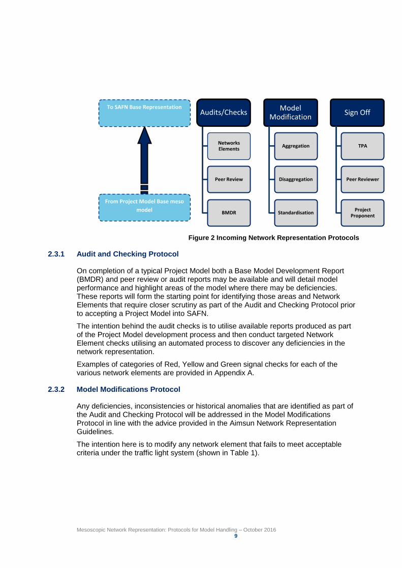
2.3 Incoming Network Representation Protocols
The Incoming Network Representation Protocols will ensure that the network representation data imported into SAFN are of a consistent standard as only models that have been undertaken in accordance with the Aimsun Network Coding Guidelines (TfNSW, 2015) will be accepted into SAFN without modification.
The Incoming Network Representation Protocols consist of three streams to ensure that consistent network representation is passed to SAFN:
1. Audits and checking of network representation within the received Project Model
2. Model modifications that are necessary to allow for integration with SAFN (this may include aggregation, disaggregation and standardisation of network elements)
3. Sign-off authority as the model moves from a Project Model to inclusion in SAFN.
This process is illustrated is Figure 2.
Mesoscopic Network Representation: Protocols for Model Handling – October 2016 9
To SAFN Base Representation
From Project Model Base meso model
TPA
Audits/Checks
Networks Elements
Peer Review
BMDR
Model Modification
Aggregation
Disaggregation
Standardisation
Sign Off
TPA
Peer Reviewer
Project Proponent
Figure 2 Incoming Network Representation Protocols
2.3.1 Audit and Checking Protocol
On completion of a typical Project Model both a Base Model Development Report (BMDR) and peer review or audit reports may be available and will detail model performance and highlight areas of the model where there may be deficiencies. These reports will form the starting point for identifying those areas and Network Elements that require closer scrutiny as part of the Audit and Checking Protocol prior to accepting a Project Model into SAFN.
The intention behind the audit checks is to utilise available reports produced as part of the Project Model development process and then conduct targeted Network Element checks utilising an automated process to discover any deficiencies in the network representation.
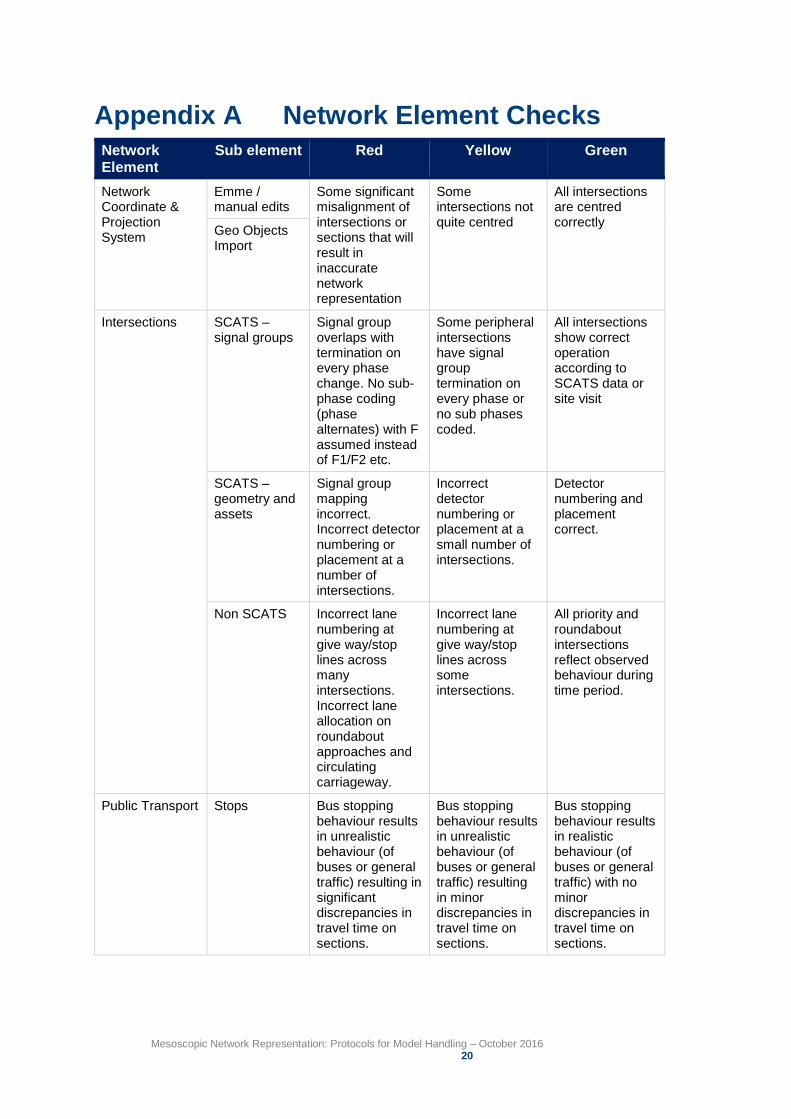
Examples of categories of Red, Yellow and Green signal checks for each of the various network elements are provided in Appendix A.
2.3.2 Model Modifications Protocol
Any deficiencies, inconsistencies or historical anomalies that are identified as part of the Audit and Checking Protocol will be addressed in the Model Modifications Protocol in line with the advice provided in the Aimsun Network Representation Guidelines.
The intention here is to modify any network element that fails to meet acceptable criteria under the traffic light system (shown in Table 1).
Mesoscopic Network Representation: Protocols for Model Handling – October 2016 10
The proposed modification process will utilise the automatic scripting developed by Aimsun proprietors, TSS, to provide a consistent approach to the representation of network elements1.
Those network element checks that are considered sub-standard, and are given a red signal, must be corrected by the Project Developer prior to the Project Model being accepted into SAFN. Other changes may be made by TPA staff as needed but only after those red signal deficiencies have been addressed by the Project Developer.
It is intended that the proposed error checking and modification activities will form part of the Project Proponents own model sign-off / approval requirements and in this way the potential for introducing additional or duplicate requirements into the model development process is avoided.
Core Area disaggregation of centroids and intersection density will be maintained where possible and centroids will follow the Travel Zone 2011 (TZ11) zonal representation as a minimum2.
Aggregation of network elements will be avoided where possible in order to preserve the work completed by the Model Developer.
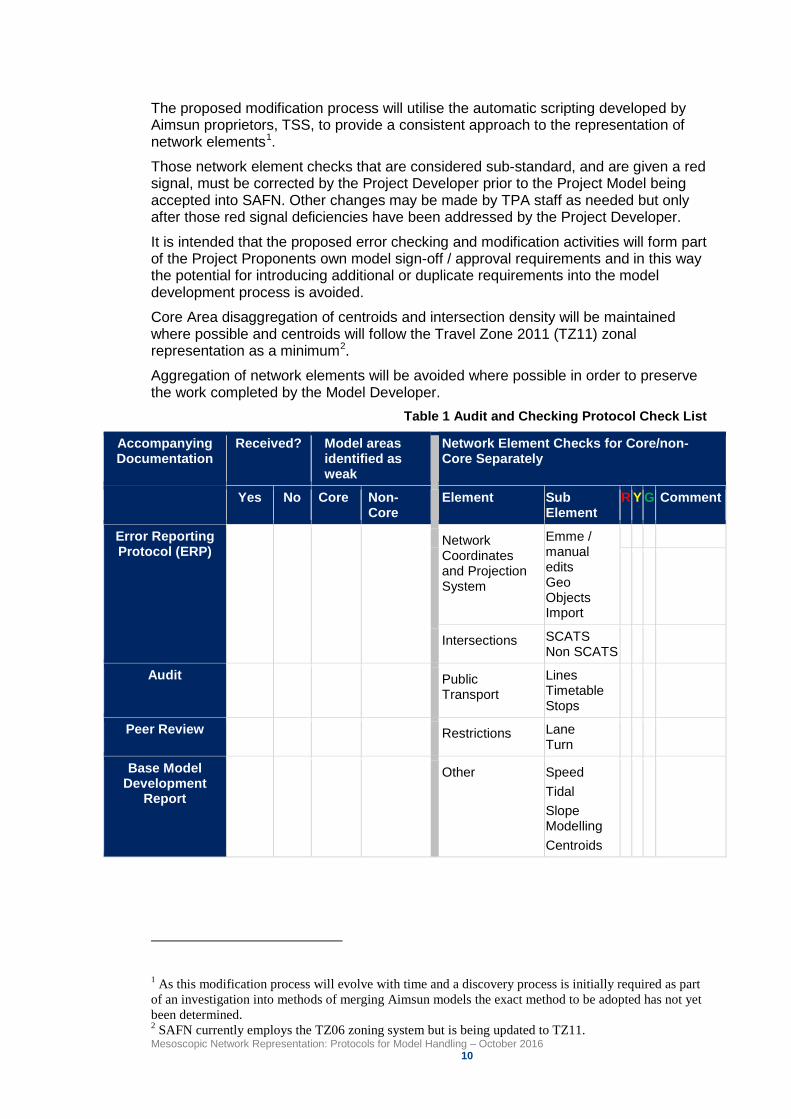
Table 1 Audit and Checking Protocol Check List
Accompanying Documentation
Received? Model areas identified as weak
Network Element Checks Core Separately
for Core/non-
Yes No Core Non-Core
Element Sub Element
R Y G Comment
Error Reporting Protocol (ERP)
Network Coordinates and Projection System
Emme / manual edits Geo Objects Import
Intersections SCATS Non SCATS
Audit Public Transport
Lines Timetable Stops
Peer Review Restrictions Lane Turn
Base Model Development
Report
Other Speed Tidal Slope Modelling Centroids
1 As this modification process will evolve with time and a discovery process is initially required as part of an investigation into methods of merging Aimsun models the exact method to be adopted has not yet been determined. 2 SAFN currently employs the TZ06 zoning system but is being updated to TZ11.
Mesoscopic Network Representation: Protocols for Model Handling – October 2016 11
2.3.3 Sign-Off Protocol
To preserve the integrity of SAFN, TPA will have the ultimate sign off authority and be responsible for accepting Project Models and modified Project Models into SAFN. TPA will fund and allocate a resource for this purpose on a project by project basis. This will ensure that a single source of truth for the base network is maintained with best practice representation of the network elements.
As the Project Models migrate towards their incorporation into SAFN, sign off authority will pass from Project Proponent to TPA to ensure a consistent approach is maintained.
2.4 Outgoing Network Representation Protocols
2.4.1 Authority to Extract
At the project inception stage, the Project Proponent will request an extract from SAFN of the agreed Project Model study area through the TPA Principal Manager Transport Forecasting. TPA will provide this in electronic format to the Model Developers along with the relevant documentation that may have accompanied the original Project Model study area/s that make up, or overlap, the Project study area.
In this way TPA will retain all relevant information that relates to the development of the original models and will also have the ability to respond to requests for background documentation within reasonable timeframes.
Project Proponents from within State Government will generally request data from SAFN through established agency or project communication channels. Alternatively access to SAFN may be requested via the TPA website or TPA email . Non-government entities may also request access to SAFN and TPA will assess the merits of the application before agreeing the commercial terms for access.
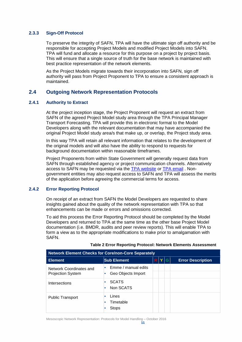
2.4.2 Error Reporting Protocol
On receipt of an extract from SAFN the Model Developers are requested to share insights gained about the quality of the network representation with TPA so that enhancements can be made or errors and omissions corrected.
To aid this process the Error Reporting Protocol should be completed by the Model Developers and returned to TPA at the same time as the other base Project Model documentation (i.e. BMDR, audits and peer review reports). This will enable TPA to form a view as to the appropriate modifications to make prior to amalgamation with SAFN.
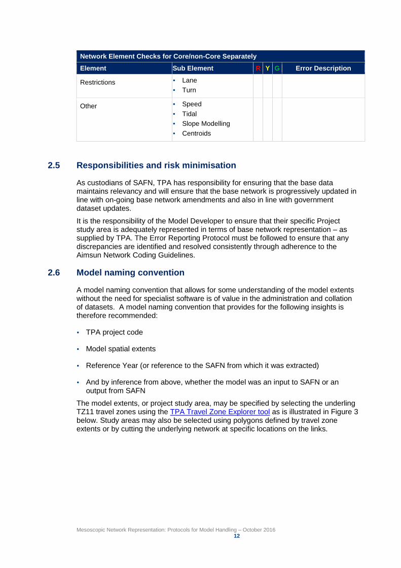
Table 2 Error Reporting Protocol: Network Elements Assessment
Network Element Checks for Core/non-Core Separately
Element Sub Element R Y G Error Description
Network Coordinates and Projection System
Emme / manual edits Geo Objects Import
Intersections SCATS Non SCATS
Public Transport Lines Timetable Stops
Mesoscopic Network Representation: Protocols for Model Handling – October 2016 12
Network Element Checks for Core/non-Core Separately
Element Sub Element R Y G Error Description
Restrictions Lane Turn
Other Speed Tidal Slope Modelling Centroids
2.5 Responsibilities and risk minimisation
As custodians of SAFN, TPA has responsibility for ensuring that the base data maintains relevancy and will ensure that the base network is progressively updated in line with on-going base network amendments and also in line with government dataset updates.
It is the responsibility of the Model Developer to ensure that their specific Project study area is adequately represented in terms of base network representation – as supplied by TPA. The Error Reporting Protocol must be followed to ensure that any discrepancies are identified and resolved consistently through adherence to the Aimsun Network Coding Guidelines.
2.6 Model naming convention
A model naming convention that allows for some understanding of the model extents without the need for specialist software is of value in the administration and collation of datasets. A model naming convention that provides for the following insights is therefore recommended:
TPA project code
Model spatial extents
Reference Year (or reference to the SAFN from which it was extracted)
And by inference from above, whether the model was an input to SAFN or an output from SAFN
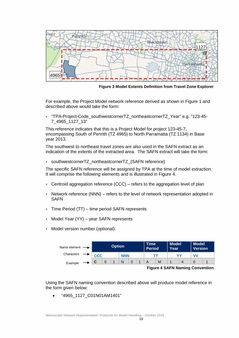
The model extents, or project study area, may be specified by selecting the underling TZ11 travel zones using the TPA Travel Zone Explorer tool as is illustrated in Figure 3 below. Study areas may also be selected using polygons defined by travel zone extents or by cutting the underlying network at specific locations on the links.
Mesoscopic Network Representation: Protocols for Model Handling – October 2016 13
4965
1127
Figure 3 Model Extents Definition from Travel Zone Explorer
For example, the Project Model network reference derived as shown in Figure 1 and described above would take the form:
“TPA-Project-Code_southwestcornerTZ_northeastcornerTZ_Year” e.g. “123-45-7_4965_1127_13”
This reference indicates that this is a Project Model for project 123-45-7, encompassing South of Penrith (TZ 4965) to North Parramatta (TZ 1134) in Base year 2013.
The southwest to northeast travel zones are also used in the SAFN extract as an indication of the extents of the extracted area. The SAFN extract will take the form:
southwestcornerTZ_northeastcornerTZ_{SAFN reference}
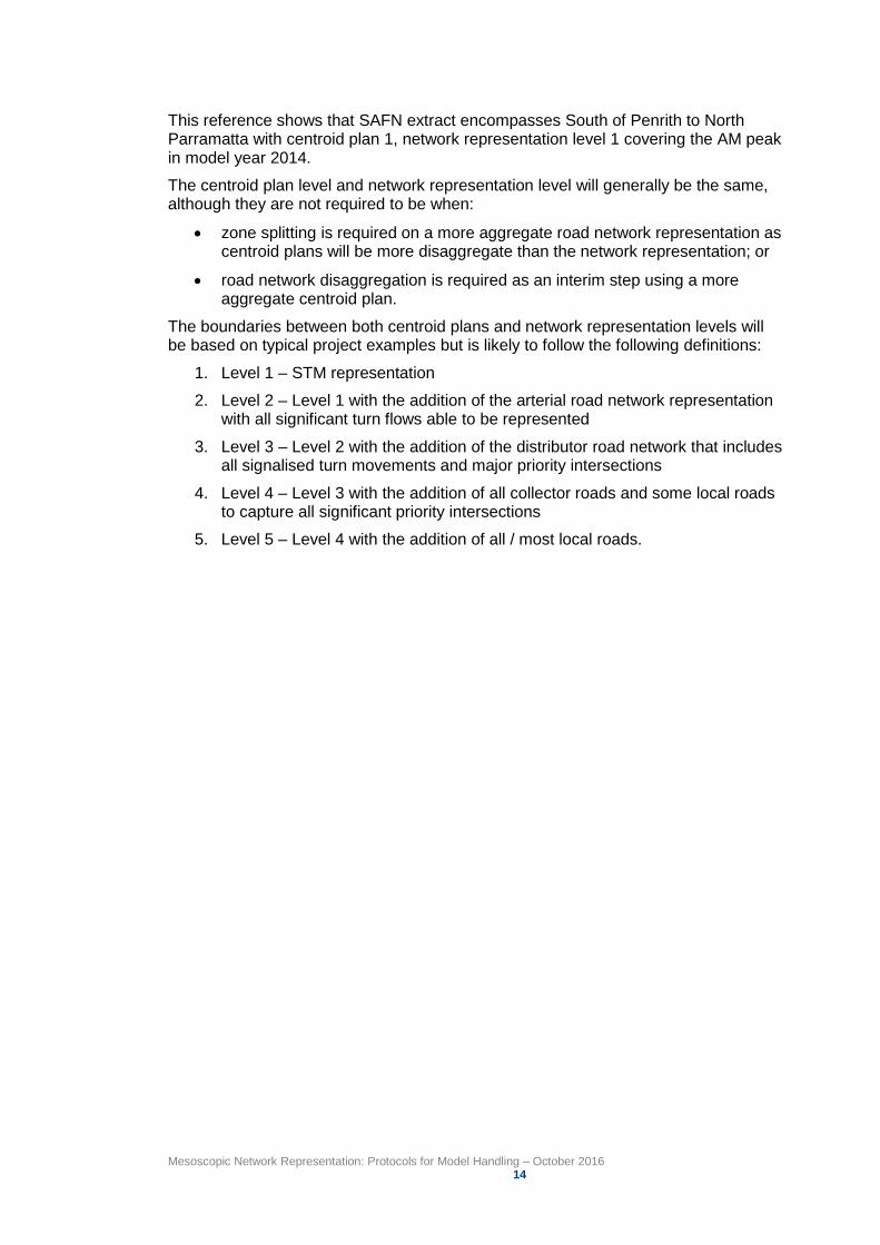
The specific SAFN reference will be assigned by TPA at the time of model extraction. It will comprise the following elements and is illustrated in Figure 4.
Centroid aggregation reference (CCC) – refers to the aggregation level of plan
Network reference (NNN) – refers to the level of network representation adopted in SAFN
Time Period (TT) – time period SAFN represents
Model Year (YY) – year SAFN represents
Model version number (optional).
Example
Name element
Characters
Option Time Period
Model Year
Model Version
CCC NNN TT YY VV C 0 1 N 0 1 A M 1 4 0 1
Figure 4 SAFN Naming Convention
Using the SAFN naming convention described above will produce model reference in the form given below:
• “4965_1127_C01N01AM1401”
Mesoscopic Network Representation: Protocols for Model Handling – October 2016 14
This reference shows that SAFN extract encompasses South of Penrith to North Parramatta with centroid plan 1, network representation level 1 covering the AM peak in model year 2014.
The centroid plan level and network representation level will generally be the same, although they are not required to be when:
• zone splitting is required on a more aggregate road network representation as centroid plans will be more disaggregate than the network representation; or
• road network disaggregation is required as an interim step using a more aggregate centroid plan.
The boundaries between both centroid plans and network representation levels will be based on typical project examples but is likely to follow the following definitions:
1. Level 1 – STM representation
2. Level 2 – Level 1 with the addition of the arterial road network representation with all significant turn flows able to be represented
3. Level 3 – Level 2 with the addition of the distributor road network that includes all signalised turn movements and major priority intersections
4. Level 4 – Level 3 with the addition of all collector roads and some local roads to capture all significant priority intersections
5. Level 5 – Level 4 with the addition of all / most local roads.
Mesoscopic Network Representation: Protocols for Model Handling – October 2016 15
3 Data sources 3.1 Key sources of network development data
A number of data sources have been identified that are of significant value to the development and maintenance of modelled networks and a list of these sources is provided in Appendix B. However, during the course of a project, Model Developers will be given access to the following data and available scripts as required:
SCATS data (detectors, signal group mapping, phasing)
Transport Info data (General Transit Feed Specification (GTFS)
Public Transport Information and Priority System (PTIPS)
Current (at base model year) aerial photography
SAFN extract – where applicable.
Note that this list is not a full list of data required to calibrate and validate a model, but represents those readily available data sources that can provide a reasonable representation of the current road network and can be considered as the minimum list of core data required to develop a new Project Model.
3.2 Data and network contemporaneity
While a number of sources for accurate network representation data exist (e.g. Land and Property Information GIS and commercially available navigable networks) aerial photography is thought to offer some advantages over these alternative sources as it provides a definitive validation of what exists on the ground on any particular date. Aerial photography is one of the most frequently updated sources of data for network as the GMA is over-flown regularly with State Government receiving contemporaneous data regularly.
Nevertheless, the contemporaneity of data must be verified to ensure the aerial photography is accurate and/or to elucidate locations that may be obscured by building shadows or tree canopies. It is the responsibility of the Model Developer to ensure that the network is representative of the base model year / month and to ensure that key elements of the network are reflected correctly.
The aerial photography required for model development should be requested through TPA by specifying the extents of the area of interest.
To reduce risks and to take ownership, or some degree of shared responsibility, the Model Developer should also record and report on the date of the aerial photography, as well as list of network changes that are known to have occurred since that date. As there is currently no formal system within State Government for identifying network changes that have occurred from any particular date, the risk that out of date aerial photography will be used to represent the existing network has to be appropriately managed by the Model Developer.
Unless the Model Developer can demonstrate they have undertaken all reasonable consultation and due diligence to ensure the accuracy of the underlying data, TPA will hold the Model Developer fully responsible for any errors and omissions.
Mesoscopic Network Representation: Protocols for Model Handling – October 2016 16
3.3 Data and the definition of typical peak periods
An advantage of the widespread coverage of SCATS throughout NSW is that it provides a rich set of both detector data and signal timing information. While there are risks around the direct application of each of these datasets it is possible to obtain robust defendable inputs for model development with some additional verification on what constitutes a typical day for both signal operation and traffic demand.
Signal operations may not be typical of peak period operations in specific areas depending on what network operations occurred during the time of the SCATS signal data extraction. A copy of any network incident reporting for the day in question should therefore be requested by the Model Developer from the Transport Management Centre through the established project contact points. Given that SCATS data is readily available and historical signal timing records are kept for many months it is also worth requesting several days of data to ensure typical conditions can be understood and modelled.
Unless the Model Developer can demonstrate they have undertaken all reasonable consultation and due diligence to ensure the accuracy of the underlying data, TPA will hold the Model Developer fully responsible for any errors and omissions.
Where data supplied is insufficient or inaccurate the Model Developer is responsible for obtaining the correct information through site visits or commissioned surveys. This additional data will be used to assist in data verification before acceptance into SAFN.
Mesoscopic Network Representation: Protocols for Model Handling – October 2016 17
4 Towards best practice protocols The preceding Protocols have been developed as a means to deliver consistent and quality assured Aimsun meso models for all projects. However, it is recognised that the Protocols are an interim measure to provide immediate improvements in model handling whilst progress is made towards a more comprehensive method of developing, maintaining and sharing transport network data.
The current recommended longer term approach is to utilise the Spatially Enabled Networks (SEN) database in ArcGIS to act as a repository of all relevant network data that can then be used by Emme or Aimsun depending on the modelling requirements.
The advantage of this approach is the ability to import to and export from proprietary software packages, including Aimsun and Emme, while facilitating the storage and maintenance of all relevant network representation data in a single recognised database form. The SEN database, however, is currently in the concept development stage.
These Protocols have been developed to address the short term need for improvement in model handling.
In developing a short term model handling process that is implemented prior to any possible future switch towards the SEN database (or alternative system), there are a number of improvements that are being introduced that will also assist with long term objectives, these include:
• Establishing a protocol for the industry to follow that introduces a consistent approach to network representation
• Interaction and amalgamation of model areas that can be used to extract future Project Model study area networks
• Immediate leverage of work completed as part of previously commissioned Project Models to help reduce costs and delivery times by providing a suitable base from which to develop future Project Models
• Develop an independent source of network representation data that can be used to verify areas that future automated processes developed under the SEN project will continue to be challenged by
• Future SCATS detectors and signal group mapping together with the GTFS route and timetable datasets, as used by the Transport Info journey planner, are likely to be accessed via SEN in the future as they both comprise spatially aware components. Although there is no current commitment to implementing a spatially aware Roads Asset Management System (RAMS) there is an opportunity to include this in the future through the SEN project as it would greatly assist the automatic maintenance and control of network representation datasets.
4.1 Moving toward SEN protocols
This Protocols document will be updated as the method of model handling moves from current practice to best practice (long term). The transition between current and best practice will rely heavily on the consistent updating and enhancing of SAFN, which ultimately will be superseded by the introduction of the SEN protocols. SAFN will nevertheless provide a valuable resource and reference datasets that can be used to verify some of the automated processes involved in establishing the SEN as
Mesoscopic Network Representation: Protocols for Model Handling – October 2016 18
well as providing a valuable starting point for those GIS functions that cannot be fully automated.
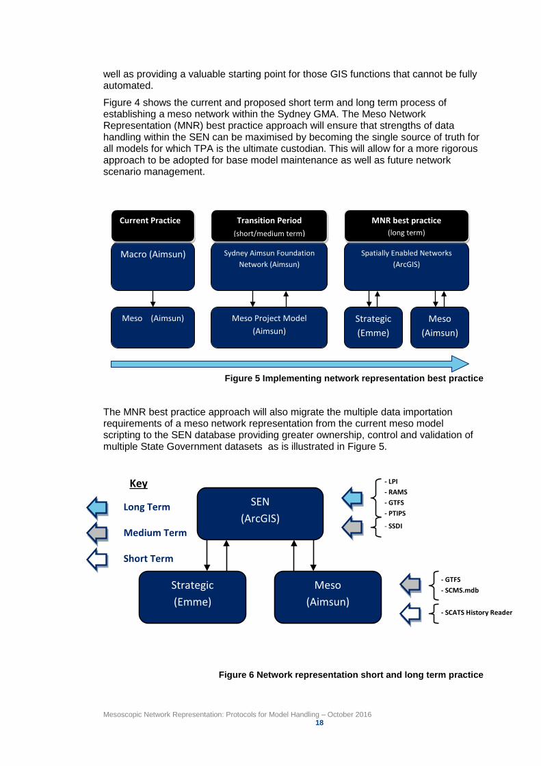
Figure 4 shows the current and proposed short term and long term process of establishing a meso network within the Sydney GMA. The Meso Network Representation (MNR) best practice approach will ensure that strengths of data handling within the SEN can be maximised by becoming the single source of truth for all models for which TPA is the ultimate custodian. This will allow for a more rigorous approach to be adopted for base model maintenance as well as future network scenario management.
Macro (Aimsun)
Meso (Aimsun)
Sydney Aimsun Foundation Network (Aimsun)
Meso Project Model (Aimsun)
Spatially Enabled Networks (ArcGIS)
Strategic (Emme)
Meso (Aimsun)
Current Practice Transition Period (short/medium term)
MNR best practice (long term)
Figure 5 Implementing network representation best practice
The MNR best practice approach will also migrate the multiple data importation requirements of a meso network representation from the current meso model scripting to the SEN database providing greater ownership, control and validation of multiple State Government datasets as is illustrated in Figure 5.
SEN (ArcGIS)
Strategic (Emme)
Meso (Aimsun)
- LPI - RAMS - GTFS - PTIPS
- SSDI
- GTFS - SCMS.mdb
- SCATS History Reader
Long Term
Medium Term
Short Term
Key
Figure 6 Network representation short and long term practice
Mesoscopic Network Representation: Protocols for Model Handling – October 2016 19
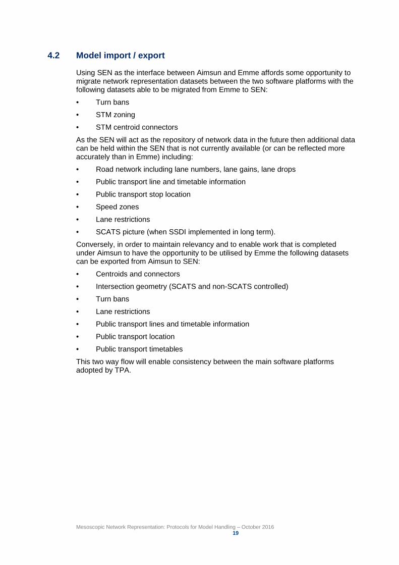
4.2 Model import / export
Using SEN as the interface between Aimsun and Emme affords some opportunity to migrate network representation datasets between the two software platforms with the following datasets able to be migrated from Emme to SEN:
• Turn bans
• STM zoning
• STM centroid connectors
As the SEN will act as the repository of network data in the future then additional data can be held within the SEN that is not currently available (or can be reflected more accurately than in Emme) including:
• Road network including lane numbers, lane gains, lane drops
• Public transport line and timetable information
• Public transport stop location
• Speed zones
• Lane restrictions
• SCATS picture (when SSDI implemented in long term).
Conversely, in order to maintain relevancy and to enable work that is completed under Aimsun to have the opportunity to be utilised by Emme the following datasets can be exported from Aimsun to SEN:
• Centroids and connectors
• Intersection geometry (SCATS and non-SCATS controlled)
• Turn bans
• Lane restrictions
• Public transport lines and timetable information
• Public transport location
• Public transport timetables
This two way flow will enable consistency between the main software platforms adopted by TPA.
Mesoscopic Network Representation: Protocols for Model Handling – October 2016 20
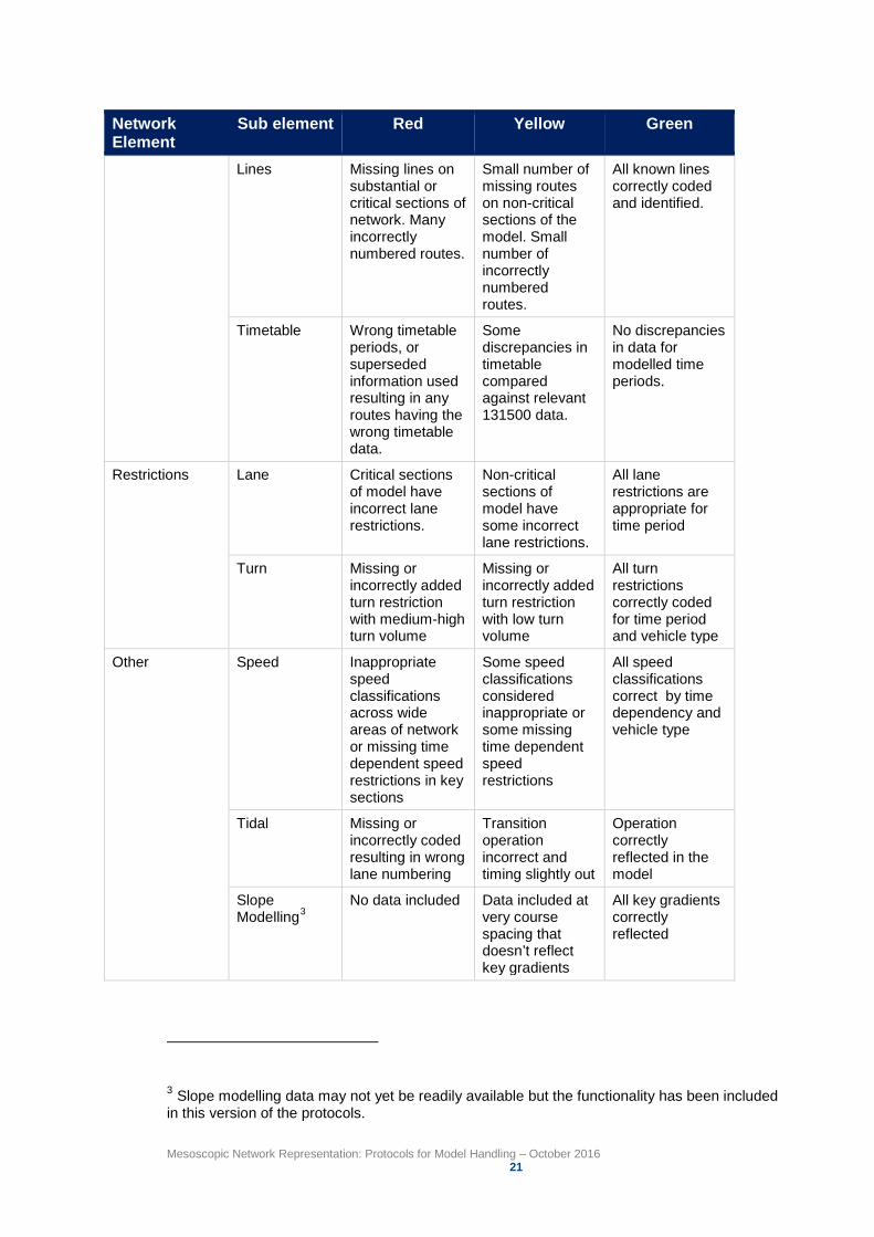
Appendix A Network Element Checks Network Element
Sub element Red Yellow Green
Network Coordinate & Projection System
Emme / manual edits
Some significant misalignment of intersections or sections that will result in inaccurate network representation
Some intersections not quite centred
All intersections are centred correctly Geo Objects
Import
Intersections SCATS – signal groups
Signal group overlaps with termination on every phase change. No sub-phase coding (phase alternates) with F assumed instead of F1/F2 etc.
Some peripheral intersections have signal group termination on every phase or no sub phases coded.
All intersections show correct operation according to SCATS data or site visit
SCATS – geometry and assets
Signal group mapping incorrect. Incorrect detector numbering or placement at a number of intersections.
Incorrect detector numbering or placement at a small number of intersections.
Detector numbering and placement correct.
Non SCATS Incorrect lane numbering at give way/stop lines across many intersections. Incorrect lane allocation on roundabout approaches and circulating carriageway.
Incorrect lane numbering at give way/stop lines across some intersections.
All priority and roundabout intersections reflect observed behaviour during time period.
Public Transport Stops Bus stopping behaviour results in unrealistic behaviour (of buses or general traffic) resulting in significant discrepancies in travel time on sections.
Bus stopping behaviour results in unrealistic behaviour (of buses or general traffic) resulting in minor discrepancies in travel time on sections.
Bus stopping behaviour results in realistic behaviour (of buses or general traffic) with no minor discrepancies in travel time on sections.
Mesoscopic Network Representation: Protocols for Model Handling – October 2016 21
Network Element
Sub element Red Yellow Green
Lines Missing lines on substantial or critical sections of network. Many incorrectly numbered routes.
Small number of missing routes on non-critical sections of the model. Small number of incorrectly numbered routes.
All known lines correctly coded and identified.
Timetable Wrong timetable periods, or superseded information used resulting in any routes having the wrong timetable data.
Some discrepancies in timetable compared against relevant 131500 data.
No discrepancies in data for modelled time periods.
Restrictions Lane Critical sections of model have incorrect lane restrictions.
Non-critical sections of model have some incorrect lane restrictions.
All lane restrictions are appropriate for time period
Turn Missing or incorrectly added turn restriction with medium-high turn volume
Missing or incorrectly added turn restriction with low turn volume
All turn restrictions correctly coded for time period and vehicle type
Other Speed Inappropriate speed classifications across wide areas of network or missing time dependent speed restrictions in key sections
Some speed classifications considered inappropriate or some missing time dependent speed restrictions
All speed classifications correct by time dependency and vehicle type
Tidal Missing or incorrectly coded resulting in wrong lane numbering
Transition operation incorrect and timing slightly out
Operation correctly reflected in the model
Slope Modelling3
No data included Data included at very course spacing that doesn’t reflect key gradients
All key gradients correctly reflected
3 Slope modelling data may not yet be readily available but the functionality has been included in this version of the protocols.
Mesoscopic Network Representation: Protocols for Model Handling – October 2016 22
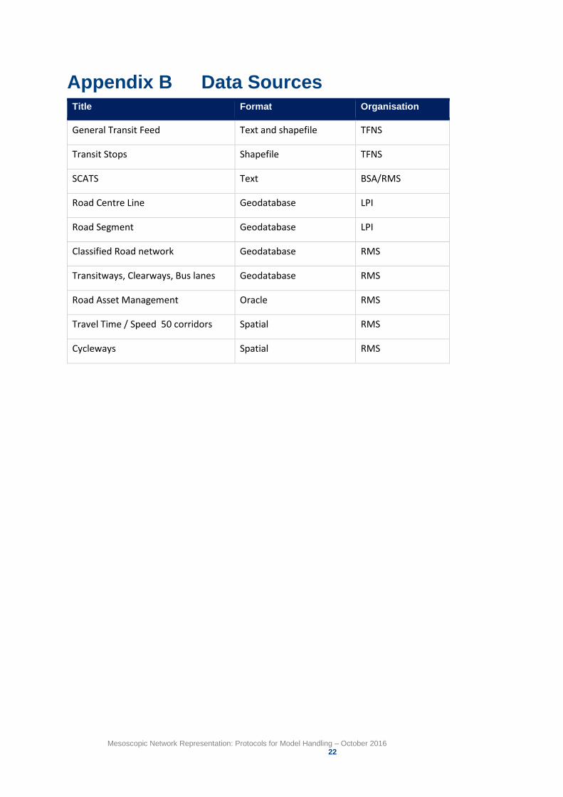
Appendix B Data Sources Title Format Organisation
General Transit Feed Text and shapefile TFNS
Transit Stops Shapefile TFNS
SCATS Text BSA/RMS
Road Centre Line Geodatabase LPI
Road Segment Geodatabase LPI
Classified Road network Geodatabase RMS
Transitways, Clearways, Bus lanes Geodatabase RMS
Road Asset Management Oracle RMS
Travel Time / Speed 50 corridors Spatial RMS
Cycleways Spatial RMS