Embed Size (px)
Citation preview
01/2011
MESA – Logica
Modular Wallform System
Logica (MRWF)
Modular Wallform System
Design Calculation

Contents
Introduction
System Overview 1
Technical Features
Connection Variation 4
Loading Limits
Concrete Pressure 11
Tie-Rods 15
Formwork Connection 16
Push-Pull Props 17
Lifting Device 18
Platform Bracket 19
Test Results 20
General Remarks
Logica Wall Formwork System –MRWF
DESIGN CALCULATION – 01/2011 www.mesaimalat.com.tr
Important Note
Sight-Check
Information
Warning
Remarks
Symbols Used
� All products of MESA should be used
according to the relevant safety regulations of
the state or country in which they are operated.
� Schematic illustrations on this manual give
only basic rules to be applied during assembly,
therefore it does not complete from the safety point
of view.
� MESA products could only be used
according to the Instruction or User Manuals,
any Technical Details given in Documents
provided by MESA.
� Any MESA products could not be combined
with the products of other manufacturers.
� Mesa Imalat reserves the right to make
technical changes in the interests of progress.
© Copyright by MESA Imalat San.ve Tic A.S.-
Ankara-Turkey

Warranty
Logica Wall Formwork System –MRWF
DESIGN CALCULATION – 01/2011 www.mesaimalat.com.tr
Warranty Period
� Limited Warranty for two (2) years is
promissed by Mesa İmalat San.ve Tic. A.Ş. for
Steel Face Formworks and Slab Formworks
unless the Operational Conditions described
below are violated.
� This warranty covers defects of steel
material, welding and painting.
� For Hydraulic Cylinders and Hydraulic
Power Units , the limited warranty period is one
(1) year.
Service Life
� Steel Face Formworks and Slab
Formworks, produced by Mesa İMALAT San.ve
Tic.A.Ş., is good for 500 concrete castings
unless The Operational Conditions described
below are violated.
Operational Conditions
� Instruction or User’s Manuals must be
used while Formwork assemblies, accessory
attachements and concrete casting.
� It is not allowed to use hummer,
sedgehummer, cranka and vs that cause physical
demage on Formworks, and also applications of
extra welding, cutting and drilling without permission
of authorities.
� It is not allowed to exceed the Max
Concrete Pressure described in Technical or
User’s Manuals.
� Formwork should be used between + 40 °C
and – 30 °C.
� Formworks should be cleaned after each
application to remove the concrete residues and
active faces should be lubricated with suitable
concrete/metal seperation oil.
� After 250 applications, maintenance should
be done at site.
� This maintenance covers the flatning of
active surface, repainting, welding and rust
control.
� After 500 applications, maintenance should
be done at work shop where the necessary
equipments exist.
� During the storage period, all active
surfaces should be lubricated with suitable oil to
prevent rusting.
� Stock area should be closed area; if it is not
possible, formworks and accessories should be
stocked in open areas by covering them with water
resistant materials.
� Maitenance procedure should be
repeated for each 250 usages after first 500
usages are exceeded.
� For HCP-hydraulic system, the allowable
working pressure must not be exceeded ( 250 bar ).
� All connections between hydraulic
cylinders, hydraulic power units and hydraulic
pipes and must be checked against leakage
before each usage.
� Electrical power supply and connections
must be suitable as written in the ınstruction or
User’s Manuals given by MESA.
Introduction System Overview
Logica Wall Formwork System –MRWF
1
DESIGN CALCULATION – 01/2011 www.mesaimalat.com.tr
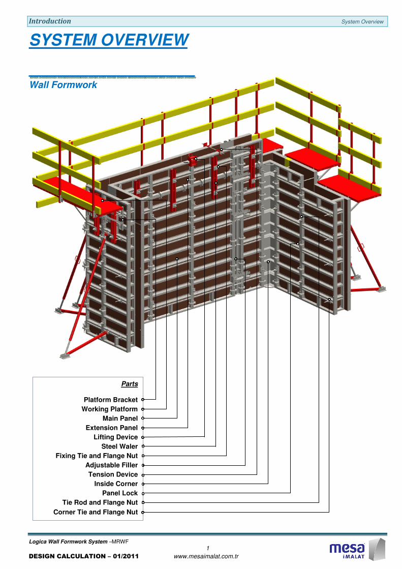
SYSTEM OVERVIEW
Wall Formwork
Parts
Platform Bracket
Working Platform
Main Panel
Extension Panel
Lifting Device
Steel Waler
Fixing Tie and Flange Nut
Adjustable Filler
Tension Device
Inside Corner
Panel Lock
Tie Rod and Flange Nut
Corner Tie and Flange Nut
Introduction System Overview
Logica Wall Formwork System –MRWF
2
DESIGN CALCULATION – 01/2011 www.mesaimalat.com.tr
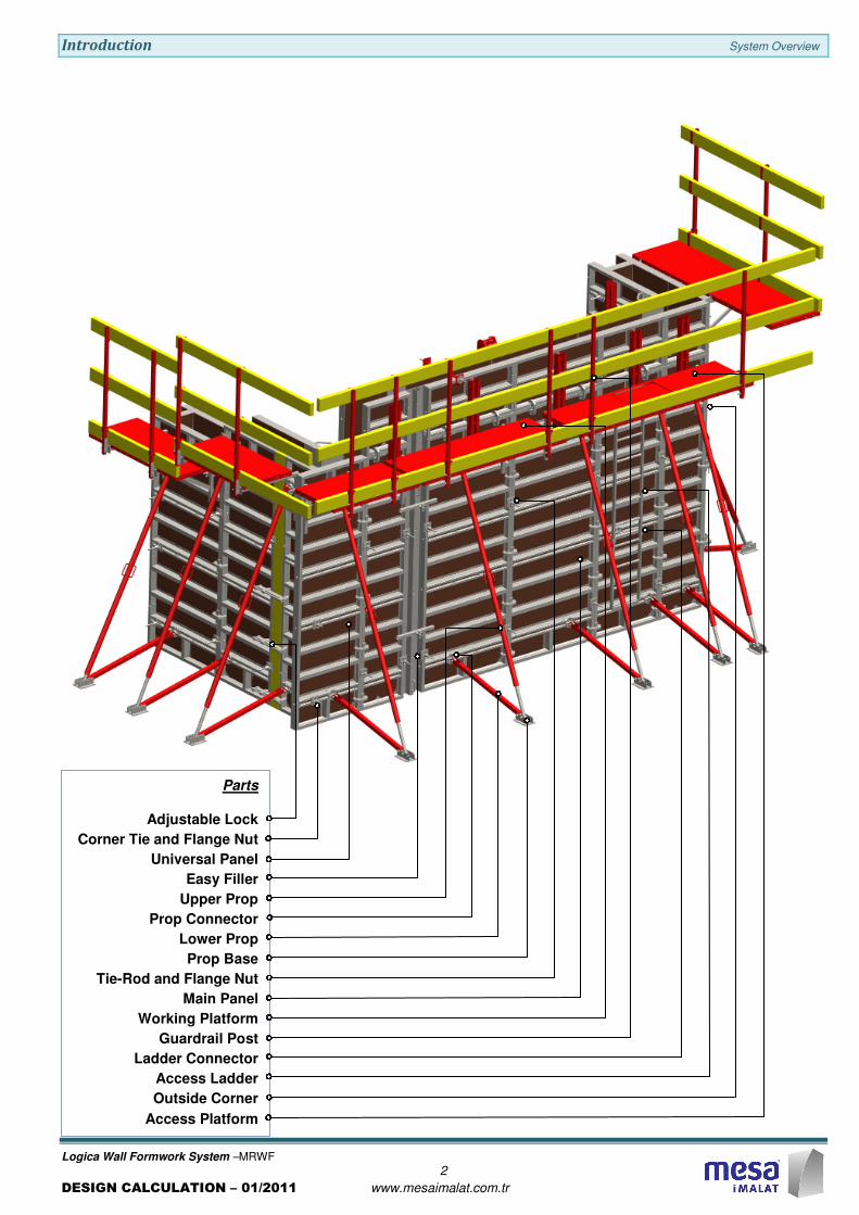
Parts
Adjustable Lock
Corner Tie and Flange Nut
Universal Panel
Easy Filler
Upper Prop
Prop Connector
Lower Prop
Prop Base
Tie-Rod and Flange Nut
Main Panel
Working Platform
Guardrail Post
Ladder Connector
Access Ladder
Outside Corner
Access Platform
Introduction System Overview
Logica Wall Formwork System –MRWF
3
DESIGN CALCULATION – 01/2011 www.mesaimalat.com.tr
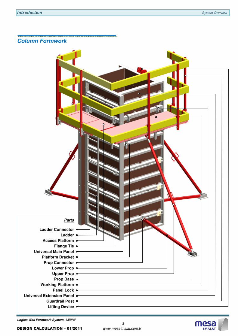
Column Formwork
Parts
Ladder Connector
Ladder
Access Platform
Flange Tie
Universal Main Panel
Platform Bracket
Prop Connector
Lower Prop
Upper Prop
Prop Base
Working Platform
Panel Lock
Universal Extension Panel
Guardrail Post
Lifting Device
Technical Features Connection Variation
Logica Wall Formwork System –MRWF
4
DESIGN CALCULATION – 01/2011 www.mesaimalat.com.tr
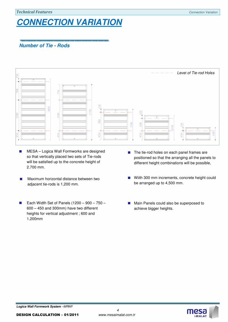
CONNECTION VARIATION
MESA – Logica Wall Formworks are designed
so that vertically placed two sets of Tie-rods
will be satisfied up to the concrete height of
2,700 mm.
Main Panels could also be superposed to
achieve bigger heights.
Level of Tie-rod Holes
The tie-rod holes on each panel frames are
positioned so that the arranging all the panels to
different height combinations will be possible,
Wiith 300 mm increments, concrete height could
be arranged up to 4,500 mm.
Maximum horizontal distance between two
adjacent tie-rods is 1,200 mm.
Each Width Set of Panels (1200 – 900 – 750 –
600 – 450 and 300mm) have two different
heights for vertical adjustment ; 600 and
1,200mm
Number of Tie - Rods

Technical Features Connection Variation
Logica Wall Formwork System –MRWF
5
DESIGN CALCULATION – 01/2011 www.mesaimalat.com.tr
Up to Concrete Height of 270 cm
Up to Concrete Height of 300 cm
Up to Concrete Height of 330 cm
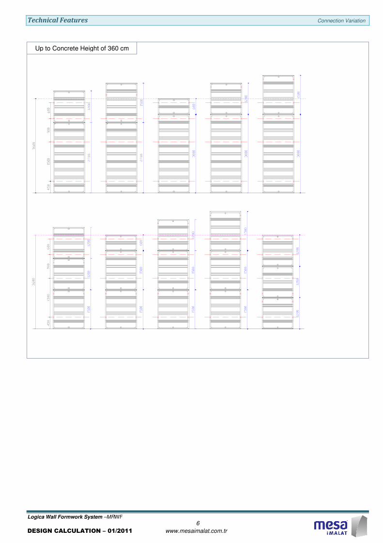
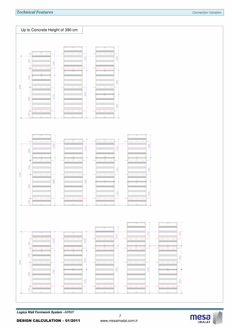
Active Tie-rod Level
Max.Concrete Height
Panel Combinations for Walls
Technical Features Connection Variation
Logica Wall Formwork System –MRWF
6
DESIGN CALCULATION – 01/2011 www.mesaimalat.com.tr
Up to Concrete Height of 360 cm
Technical Features Connection Variation
Logica Wall Formwork System –MRWF
7
DESIGN CALCULATION – 01/2011 www.mesaimalat.com.tr
Up to Concrete Height of 390 cm
Technical Features Connection Variation
Logica Wall Formwork System –MRWF
8
DESIGN CALCULATION – 01/2011 www.mesaimalat.com.tr
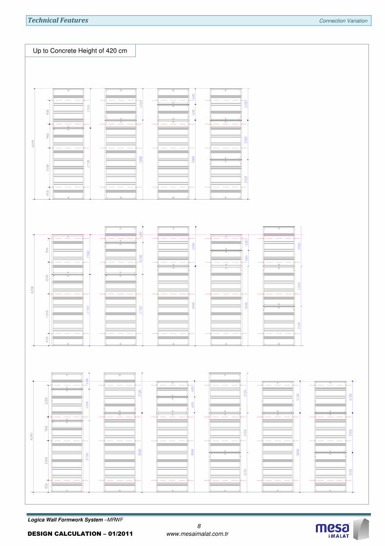
Up to Concrete Height of 420 cm
Technical Features Connection Variation
Logica Wall Formwork System –MRWF
9
DESIGN CALCULATION – 01/2011 www.mesaimalat.com.tr
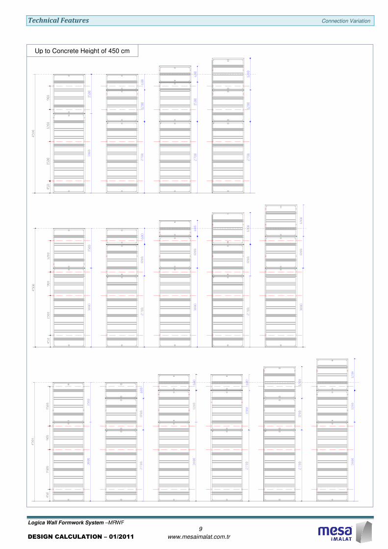
Up to Concrete Height of 450 cm

Technical Features Connection Variation
Logica Wall Formwork System –MRWF
10
DESIGN CALCULATION – 01/2011 www.mesaimalat.com.tr
For the column sizes greater than 1,100 mm;
Extra Tie-Rod should connect the reciprocal
panels.
Adjustment on Column Formwork
MESA – Logica Column Formworks are made up
of Logica Universal Panels with three different
widths of 1,200 – 900 – 600 mm.
Each edge of the columns are sized by adjusting
the connection points with the holes on the panels.
Adjusting Holes allow to adjust the size of the
column with 50mm incrementation (d).
1 4 2 3 7 6 5 10 9 8 11 12 13 14 15 16 17 18 19 20 21
Detail A
Detail A
Wmax
Wmax
Wmax
Wmax
d
Wmin
Wmin
Wmin
Wmin
W
Hole No.
Column Tie
Embedded Nut
If the size of the column is greater than 1,100 mm
then it is possible to use two or more Universal
Panels which are connected to each other side by
side.
1200 900 600
1 1,100 (Wmax) 800 (Wmax) 500 (Wmax)
2 1,050 750 450
3 1,000 700 400
4 950 650 350
5 900 600 300
6 850 550 250
7 800 500 200 (Wmin)
8 750 450 150
9 700 400 100
10 650 350
11 600 300
12 550 250
13 500 200 (Wmin)
14 450 150
15 400 100
16 350
17 300
18 250
19 200 (Wmin)
20 150
21 100
W distance (mm) for Different Widths
of Column formworks
Hole No.sPanel Widths
Loading Limits Concrete Pressure
Logica Wall Formwork System –MRWF
11
DESIGN CALCULATION – 01/2011 www.mesaimalat.com.tr
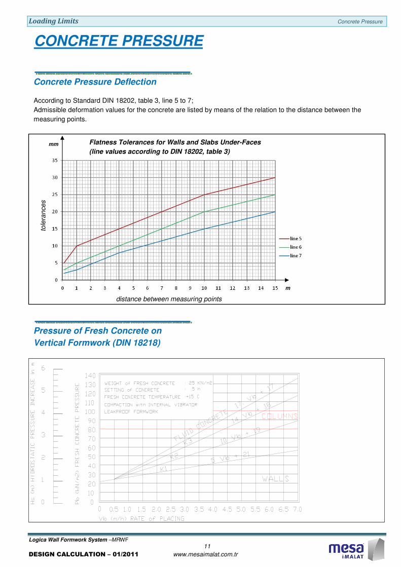
According to Standard DIN 18202, table 3, line 5 to 7;
Admissible deformation values for the concrete are listed by means of the relation to the distance between the
measuring points.
Flatness Tolerances for Walls and Slabs Under-Faces
(line values according to DIN 18202, table 3)
m
mm
tole
rances
distance between measuring points
Concrete Pressure Deflection
CONCRETE PRESSURE
Pressure of Fresh Concrete on
Vertical Formwork (DIN 18218)
Loading Limits Concrete Pressure
Logica Wall Formwork System –MRWF
12
DESIGN CALCULATION – 01/2011 www.mesaimalat.com.tr
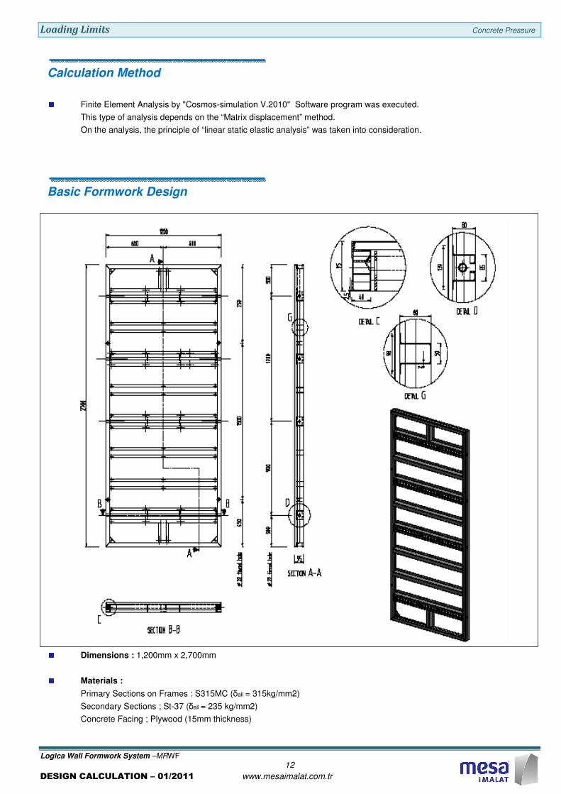
Basic Formwork Design
Dimensions : 1,200mm x 2,700mm
Materials :
Primary Sections on Frames : S315MC (δall = 315kg/mm2)
Secondary Sections ; St-37 (δall = 235 kg/mm2)
Concrete Facing ; Plywood (15mm thickness)
Calculation Method
Finite Element Analysis by "Cosmos-simulation V.2010" Software program was executed.
This type of analysis depends on the “Matrix displacement” method.
On the analysis, the principle of “linear static elastic analysis” was taken into consideration.
Loading Limits Concrete Pressure
Logica Wall Formwork System –MRWF
13
DESIGN CALCULATION – 01/2011 www.mesaimalat.com.tr
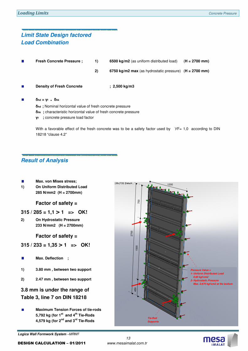
Limit State Design factored
Load Combination
Fresh Concrete Pressure ; 1) 6500 kg/m2 (as uniform distributed load) (H = 2700 mm)
2) 6750 kg/m2 max (as hydrostatic pressure) (H = 2700 mm)
Density of Fresh Concrete ; 2,500 kg/m3
δhd = γf . δhk
δhd ; Nominal horizontal value of fresh concrete pressure
δhk ; characteristic horizontal value of fresh concrete pressure
γf ; concrete pressure load factor
With a favorable effect of the fresh concrete was to be a safety factor used by УF= 1,0 according to DIN
18218 “clause 4.2”
Result of Analysis
Max. von Mises stress;
1) On Uniform Distributed Load
285 N/mm2 (H = 2700mm)
Factor of safety =
315 / 285 = 1,1 > 1 => OK!
2) On Hydrostatic Pressure
233 N/mm2 (H = 2700mm)
Factor of safety =
315 / 233 = 1,35 > 1 => OK!
Max. Deflection ;
1) 3.80 mm , between two support
2) 2.47 mm , between two support
3.8 mm is under the range of
Table 3, line 7 on DIN 18218
Maximum Tension Forces of tie-rods
5,792 kg (for 1st
and 4th
Tie-Rods
4,579 kg (for 2nd
and 3rd
Tie-Rods
1200
27
00
Tie-Rod
Supports
Pressure Value =
1- Uniform Distributed Load
0.65 kgf/cm2
2- Hydrostatic Pressure
Max. 0.675 kgf/cm2 at the bottom
15
00
75
0
45
0
Loading Limits Concrete Pressure
Logica Wall Formwork System –MRWF
14
DESIGN CALCULATION – 01/2011 www.mesaimalat.com.tr
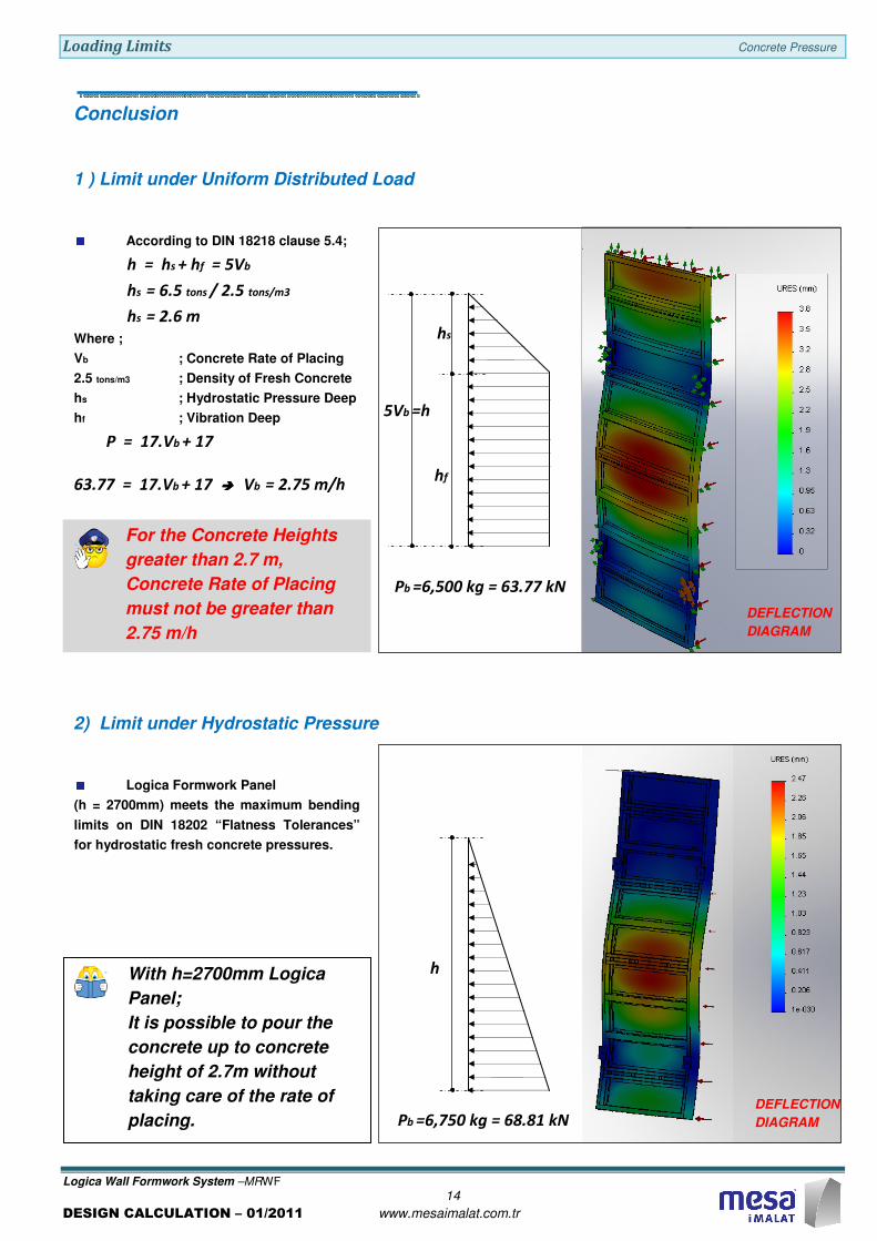
With h=2700mm Logica
Panel;
It is possible to pour the
concrete up to concrete
height of 2.7m without
taking care of the rate of
placing.
For the Concrete Heights
greater than 2.7 m,
Concrete Rate of Placing
must not be greater than
2.75 m/h
Conclusion
DEFLECTION
DIAGRAM
1 ) Limit under Uniform Distributed Load
2) Limit under Hydrostatic Pressure
Logica Formwork Panel
(h = 2700mm) meets the maximum bending
limits on DIN 18202 “Flatness Tolerances”
for hydrostatic fresh concrete pressures.
Pb =6,500 kg = 63.77 kN
hs
hf
5Vb =h
According to DIN 18218 clause 5.4;
h = hs + hf = 5Vb
hs = 6.5 tons / 2.5 tons/m3
hs = 2.6 m
Where ;
Vb ; Concrete Rate of Placing
2.5 tons/m3 ; Density of Fresh Concrete
hs ; Hydrostatic Pressure Deep
hf ; Vibration Deep
P = 17.Vb + 17
63.77 = 17.Vb + 17 ���� Vb = 2.75 m/h
Pb =6,750 kg = 68.81 kN
h
DEFLECTION
DIAGRAM
Loading Limits Tie-Rods
Logica Wall Formwork System –MRWF
15
DESIGN CALCULATION – 01/2011 www.mesaimalat.com.tr
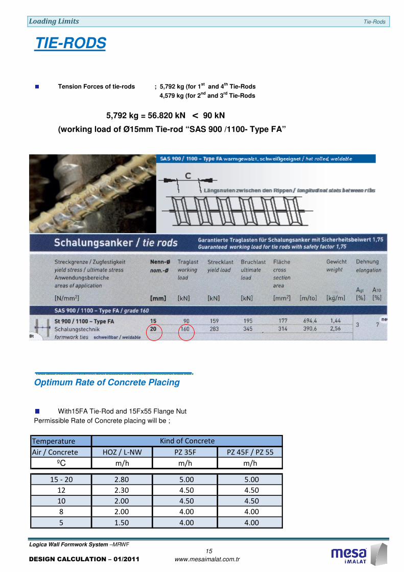
Tension Forces of tie-rods ; 5,792 kg (for 1st
and 4th
Tie-Rods
4,579 kg (for 2nd
and 3rd
Tie-Rods
5,792 kg = 56.820 kN < 90 kN
(working load of Ø15mm Tie-rod “SAS 900 /1100- Type FA”
TIE-RODS
Optimum Rate of Concrete Placing
With15FA Tie-Rod and 15Fx55 Flange Nut
Permissible Rate of Concrete placing will be ;
Temperature
Air / Concrete HOZ / L-NW PZ 35F PZ 45F / PZ 55
ºC m/h m/h m/h
15 - 20 2.80 5.00 5.00
12 2.30 4.50 4.50
10 2.00 4.50 4.50
8 2.00 4.00 4.00
5 1.50 4.00 4.00
Kind of Concrete
Loading Limits Formwork Connection
Logica Wall Formwork System –MRWF
16
DESIGN CALCULATION – 01/2011 www.mesaimalat.com.tr
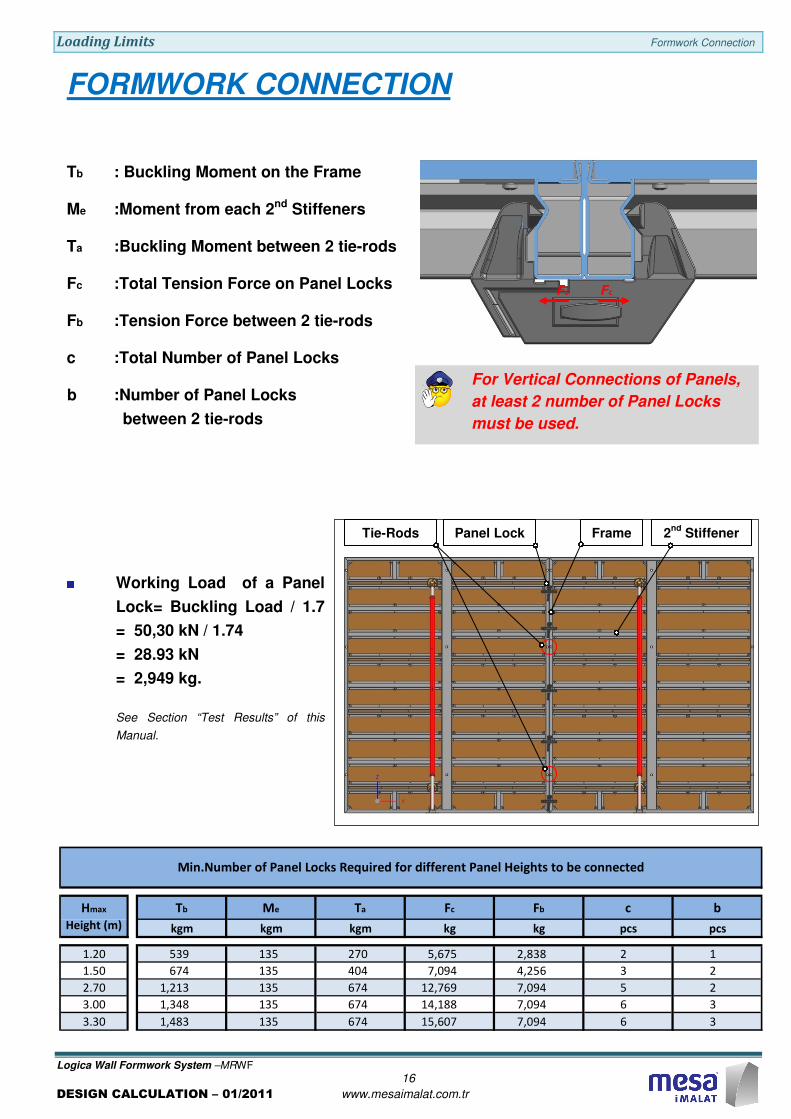
For Vertical Connections of Panels,
at least 2 number of Panel Locks
must be used.
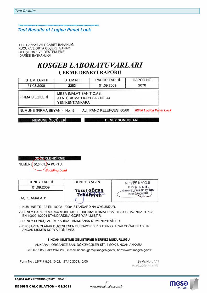
FORMWORK CONNECTION
Working Load of a Panel
Lock= Buckling Load / 1.7
= 50,30 kN / 1.74
= 28.93 kN
= 2,949 kg.
See Section “Test Results” of this
Manual.
Tb : Buckling Moment on the Frame
Me :Moment from each 2nd Stiffeners
Ta :Buckling Moment between 2 tie-rods
Fc :Total Tension Force on Panel Locks
Fb :Tension Force between 2 tie-rods
c :Total Number of Panel Locks
b :Number of Panel Locks
between 2 tie-rods
Fc Fc
Frame 2nd
Stiffener Tie-Rods Panel Lock
Tb Me Ta Fc Fb c b
kgm kgm kgm kg kg pcs pcs
1.20 539 135 270 5,675 2,838 2 1
1.50 674 135 404 7,094 4,256 3 2
2.70 1,213 135 674 12,769 7,094 5 2
3.00 1,348 135 674 14,188 7,094 6 3
3.30 1,483 135 674 15,607 7,094 6 3
Min.Number of Panel Locks Required for different Panel Heights to be connected
Hmax
Height (m)

Loading Limits Push-Pull Props
Logica Wall Formwork System –MRWF
17
DESIGN CALCULATION – 01/2011 www.mesaimalat.com.tr
60° < X° < 70°
Connections of Push-Pull Props
should be close to Vertical Profiles
of Panel Frames.
PUSH-PULL PROPS
K2d
Kv
Kh
Ka
K1d X°
Wind Speed
w = 151 km/h
Wind Pressure
q = 1.43 kN/m2
Up to 100 m above ground
(Cf = 1.3 DIN 1055)
Axial Working Load of
Mesa-Push Pull Prop
Kall = 35.12 kN / 1.7
= 20.65 kN
See Section “Test Results” of this
Manual.
q = 1.43 kN/m2
e : Push Pull Prop Interval
K1d : Axial Load
K2d : Axial Load
Ka : Support Reaction
Kh : Support Reaction
Kv : Support Reaction
L2d : 1.5 m (max.)
H2d
L2d
emax
Wmax
Hmax
2.40 3.00 3.30 3.60 3.90
2.70 11.58 14.48 15.93 17.37 18.82
3.00 12.87 16.09 17.70 19.31 20.91
3.30 14.16 17.70 19.47 21.24 23.01
3.60 15.44 19.31 21.24 23.17 25.10
3.90 16.73 20.91 23.01 25.10 27.19
4.20 18.02 22.52 24.77 27.03 29.28
4.50 19.31 24.13 26.54 28.96 31.37
Maximum Axial Loads for different Panel Areas supported
by Two sets of Push-Pull Prop
Wmax = 2 x emax
Hmax
Height (m)
e - Push-Pull Prop interval (m)
Loading Limits Lifting Device
Logica Wall Formwork System –MRWF
18
DESIGN CALCULATION – 01/2011 www.mesaimalat.com.tr
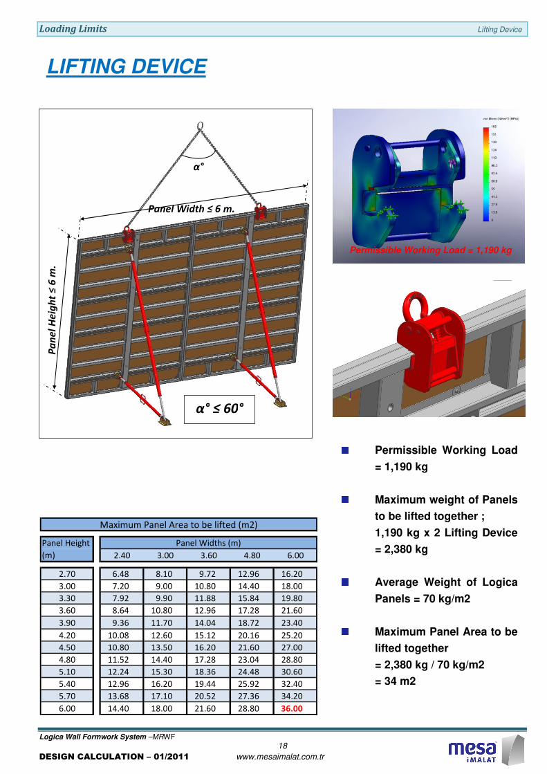
LIFTING DEVICE
Permissible Working Load
= 1,190 kg
Maximum weight of Panels
to be lifted together ;
1,190 kg x 2 Lifting Device
= 2,380 kg
Average Weight of Logica
Panels = 70 kg/m2
Maximum Panel Area to be
lifted together
= 2,380 kg / 70 kg/m2
= 34 m2
Permissible Working Load = 1,190 kg
Panel Width ≤ 6 m.
Pa
ne
l H
eig
ht
≤ 6
m.
α°
α° ≤ 60°
2.40 3.00 3.60 4.80 6.00
2.70 6.48 8.10 9.72 12.96 16.20
3.00 7.20 9.00 10.80 14.40 18.00
3.30 7.92 9.90 11.88 15.84 19.80
3.60 8.64 10.80 12.96 17.28 21.60
3.90 9.36 11.70 14.04 18.72 23.40
4.20 10.08 12.60 15.12 20.16 25.20
4.50 10.80 13.50 16.20 21.60 27.00
4.80 11.52 14.40 17.28 23.04 28.80
5.10 12.24 15.30 18.36 24.48 30.60
5.40 12.96 16.20 19.44 25.92 32.40
5.70 13.68 17.10 20.52 27.36 34.20
6.00 14.40 18.00 21.60 28.80 36.00
Panel Height
(m)
Panel Widths (m)
Maximum Panel Area to be lifted (m2)
Loading Limits Lifting Device
Logica Wall Formwork System –MRWF
19
DESIGN CALCULATION – 01/2011 www.mesaimalat.com.tr
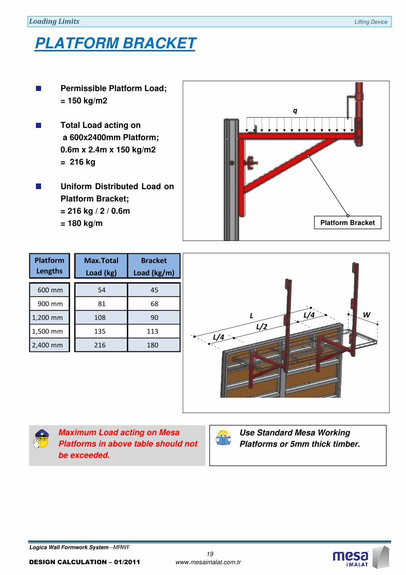
Maximum Load acting on Mesa
Platforms in above table should not
be exceeded.
Use Standard Mesa Working
Platforms or 5mm thick timber.
PLATFORM BRACKET
Platform Bracket
Permissible Platform Load;
= 150 kg/m2
Total Load acting on
a 600x2400mm Platform;
0.6m x 2.4m x 150 kg/m2
= 216 kg
Uniform Distributed Load on
Platform Bracket;
= 216 kg / 2 / 0.6m
= 180 kg/m
q
Max.Total Bracket
Load (kg) Load (kg/m)
600 mm 54 45
900 mm 81 68
1,200 mm 108 90
1,500 mm 135 113
2,400 mm 216 180
Platform
Lengths
L
L/4
L/4
L/2
W

Test Results
Logica Wall Formwork System –MRWF
20
DESIGN CALCULATION – 01/2011 www.mesaimalat.com.tr
TEST RESULTS
Test Results of Mesa Push-Pull Props
Test Results
Logica Wall Formwork System –MRWF
21
DESIGN CALCULATION – 01/2011 www.mesaimalat.com.tr
Test Results of Logica Panel Lock
Buckling Load
80/80 Logica Panel Lock
Notes
Logica Wall Formwork System - MRWF
DESIGN CALCULATION – 01/2011 www.mesaimalat.com.tr