Embed Size (px)
Citation preview
Merlin GerinCircuit breakerapplication guide
M M M M
M
M
M
M
M M M M M
MERLIN GERIN
multi 9C60NC63400Va6000
24234 2 4
10kA IEC 947.2
O - OFFO - OFFO - OFFO - OFF
6 8
1 3 5 7
MERLIN GERIN
multi 9C60NC25230Va6000
24178
O - OFF
10 kA IEC 947.2
MERLIN GERIN
multi 9C60NC63400Va6000
24234 2 4
10kA IEC 947.2
O - OFFO - OFFO - OFFO - OFF
6 8
1 3 5 7
1.5
2
3
4 5
6
8
10xIr
Im
.63
.7
.8
.85 .9
.95
.98
1xIn
IrSTR 22 SE90
105%Ir
alarm
ImIr
I n = 2 5 0 A
250N
P93083
OFF
MERLIN GERINcompactNS250 NUi 750V. Uimp 8kV.
220/240380/415440500660/690250
853635308
50
cat A
IEC947-2UTE VDE BS CEI UNE NEMA
Ue(V)
Icu(kA)
Ics=100% Icu
160/250Apushto
trip
pushto
trip
250N
P93083
1.5
2
3
4 5
6
8
10xIr
Im
.63
.7
.8
.85 .9
.95
.98
1xIn
IrSTR 22 SE90
105%Ir
alarm
ImIr
I n = 2 5 0 A
OFF
MERLIN GERINcompactNS250 NUi 750V. Uimp 8kV.
220/240380/415440500660/690250
85363530
850
cat A
IEC947-2UTE VDE BS CEI UNE NEMA
Ue(V)
Icu(kA)
Ics=100% Icu
160/250Apushto
trip
pushto
trip
MERLIN GERIN
multi 9ID'clicC32
40 mA
∆n 0,030A230Va
20564
20564
ID'clicbi 40 A
BS EN 61009
a3000
3
N 1L1 3L2
I . ON
MERLIN GERINmulti 9NG 125L
In = 125A
220/240V380/415V440V500V
Ue(V)5025156
IEC 947.218806
Icu(kA)
1.5
2
3
4 5
6
8
10xIr
Im
.63
.7
.8
.85 .9
.95
.98
1xIn
IrSTR 22 SE90
105%Ir
alarm
ImIr
I n = 2 5 0 A
250N
P93083
OFF
MERLIN GERINcompactNS250 NUi 750V. Uimp 8kV.
220/240380/415440500660/690250
853635308
50
cat A
IEC947-2UTE VDE BS CEI UNE NEMA
Ue(V)
Icu(kA)
Ics=100% Icu
160/250Apushto
trip
pushto
trip
Ic
µP
>Ir
>Im
test faultSTR 53 UE 60 75 90 105 %Ir
IImIrIo
tr tm(s)
x Inx Irx Iox In
on I2t off(s) at 1.5 Ir
test
R
tr
tm
ImIr I
MERLIN GERINcompact
NS400 HUi 750V. Uimp 8kV.
Ue(V)
220/240
380/415
440
500/525
660/690
1007065
40
35
IEC 947-2UTE VDE BS CEIUNE NEMA
Icu(kA)
cat B
Ics = 100% IcuIcw 6kA / 0,25s
In = 400A
.8
1
.63
.5
.9 .93.95
.98
.88
.85
.8 1
4 56
8
3
2
1.5 10
4 68
10
3
2
1.5 12
.3 .3.2
.1
.2
.1
0 0
120 24060
30
15 240
.9 .93.95
.98
.88
.85
.8 1
pushto
trip
pushto
trip400
250N
P93083
1.5
2
3
4 5
6
8
10xIr
Im
.63
.7
.8
.85 .9
.95
.98
1xIn
IrSTR 22 SE90
105%Ir
alarm
ImIr
I n = 2 5 0 A
OFF
MERLIN GERINcompactNS250 NUi 750V. Uimp 8kV.
220/240380/415440500660/690250
853635308
50
cat A
IEC947-2UTE VDE BS CEI UNE NEMA
Ue(V)
Icu(kA)
Ics=100% Icu
160/250Apushto
trip
pushto
trip
Reset
resetApIgI ∆n
IsdI i
Ir
Micrologic 70
Ics = 100% Icu
220/440525690
10010085
Icw 85kA/1s
NX 32 H 2
cat.B
IEC 947-2
UTE VDE BS CEI UNE AS NEMAEN 60947-2
50/60Hz
Ue Icu(V) (kA)
0 1 2 5 3
push OFF push ON
O OFF discharged
1
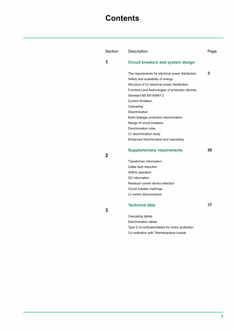
Contents
Description
Circuit breakers and system design
The requirements for electrical power distribution
Safety and availability of energy
Structure of LV electrical power distribution
Functions and technologies of protection devices
Standard BS EN 60947-2
Current limitation
Cascading
Discrimination
Earth leakage protection discrimination
Range of circuit breakers
Discrimination rules
LV discrimination study
Enhanced discrimination and cascading
Supplementary requirements
Transformer information
Cable fault reduction
400Hz operation
DC information
Residual current device selection
Circuit breaker markings
LV switch disconnectors
Technical data
Cascading tables
Discrimination tables
Type 2 co-ordinationtables for motor protection
Co-ordination with Telemecanique busbar
Section
1
2
3
Page
3
55
77
2
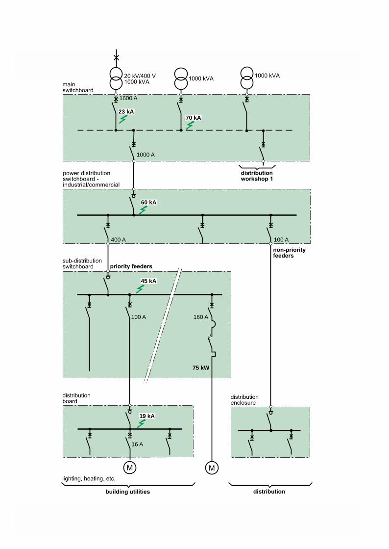
1000 kVA
1000 A
M M
100 A400 A
100 A 160 A
75 kW
16 A
20 kV/400 V1000 kVA
1600 A
1000 kVA
19 kA
45 kA
60 kA
23 kA70 kA
mainswitchboard
building utilities
lighting, heating, etc.
distributionboard
sub-distributionswitchboard
power distributionswitchboard -industrial/commercial
non-priorityfeeders
priority feeders
distribution
distributionenclosure
distributionworkshop 1

3
Section 1System requirements
Circuit breakers and system design
Safety and availability of energy
Structure of LV electrical power distribution
Functions and technologies of protection devices
Standard BS EN 60947-2
Current limitation
Cascading
Discrimination
Discrimination rules
Earth leakage protection discrimination
Coordination of protection devices
Range of circuit breakers
LV discrimination study
Enhanced discrimination and cascading
Page
5
6
7
10
15
19
21
25
26
28
30
43
46
4
Glossary
EDW:
SCPD:
IEC:
BS:
CT:
CU:
MSB:
BBT:
MV:
Isc:
Isc(D1):
Usc:
MCCB:
BC:
Icu(*):
IcuD1(*)
Ue:
Ui:
Uimp:
In:
Ith:
Ithe:
Iu:
Icm:
Icu:
Ics:
Icw:
Ir:
1.05 x Ir:
1.30 x Ir:
Ii:
Isd:
ElectroDynamic Withstand
Short circuit protection device
International Electrotechnical Commission
British Standard
Current transformers
control Unit
Main Switchboard
Busbar Trunking
Medium Voltage (1kV to 36kV)
Short-circuit current
Short-circuit current at the point D1 is installed
Short-circuit voltage
Moulded case circuit-breaker
Breaking Capacity
Ultimate Breaking Capacity
Ultimate Breaking Capacity of D1
Rated operational voltage
Rated insulation voltage
Rated impulse withstand voltage
Rated operational current
Conventional free air thermal current
Conventional enclosed thermal current
Rated uninterrupted current
Rated short-circuit making capacity
Rated ultimate short-circuit breaking capacity
Rated service breaking capacity
Rated short time withstand current
Adjustable overload setting current
Conventional non-tripping current
Conventional tripping current
Instantaneous tripping setting current
Short time tripping setting current
5
The design of LV installations leads to basic protection devicesbeing fitted for three types of faults:c overloadsc short-circuitsc insulation faults.
Operation of these protection devices must allow for:c the statutory aspects, particularly relating to safety of people,c technical and economic requirements.
The chosen switchgear must:c withstand and eliminate faults at optimised cost with respect to the necessaryperformance,c limit the effect of a fault to the smallest part possible of the installation in order toensure continuity of supply.
Achievement of these objectives requires coordination of protection deviceperformance, necessary for:c managing safety and increasing durability of the installation by limiting stresses,c managing availability by eliminating the fault by means of the circuit-breakerimmediately upstream
The circuit-breaker coordination means are:c cascadingc discrimination.
If the insulation fault is specifically dealt with by earth fault protection devices,discrimination of the residual current devices (RCDs) must also be guaranteed.
Safety and availability of energyare the operator s primerequirements.Coordination of protection devicesensures these needs are met atoptimised cost.
Safety and availability of energy
The requirements of electrical power distribution
6
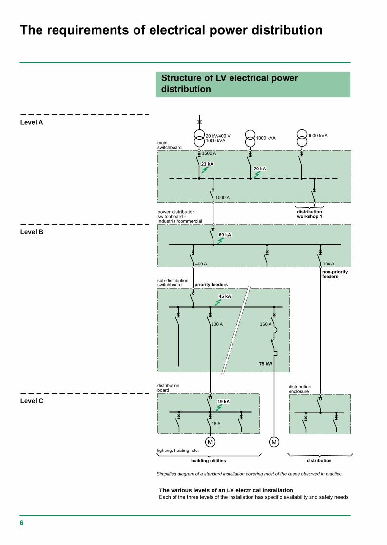
The various levels of an LV electrical installationEach of the three levels of the installation has specific availability and safety needs.
Structure of LV electrical powerdistribution
The requirements of electrical power distribution
Simplified diagram of a standard installation covering most of the cases observed in practice.
1000 kVA
1000 A
M M
100 A400 A
100 A 160 A
75 kW
16 A
20 kV/400 V1000 kVA
1600 A
1000 kVA
19 kA
45 kA
60 kA
23 kA70 kA
mainswitchboard
building utilities
lighting, heating, etc.
distributionboard
sub-distributionswitchboard
power distributionswitchboard -industrial/commercial
non-priorityfeeders
priority feeders
distribution
distributionenclosure
distributionworkshop 1
Level A
Level B
Level C
7
Circuit-breaker functionsThis connection device is able to close and break a circuit regardless of current up toits breaking capacity.The functions to be performed are:c close the circuit,c conduct current,c open the circuit and break the current,c guarantee isolation.The requirements concerning installation, cost optimisation, management ofavailability and safety generate technological choices concerning the circuit-breaker.
Level A: the Main Switchboard (MSB)This unit is the key to the entire electrical power distribution: availability of supply isessential in this part of the installation.
c Short-circuit currents are high due to:v the proximity of the LV sources,v amply sized busbars for conveying high currents.
ccccc This is the area of the power circuit-breakers
Functions and technologies of theprotection devices
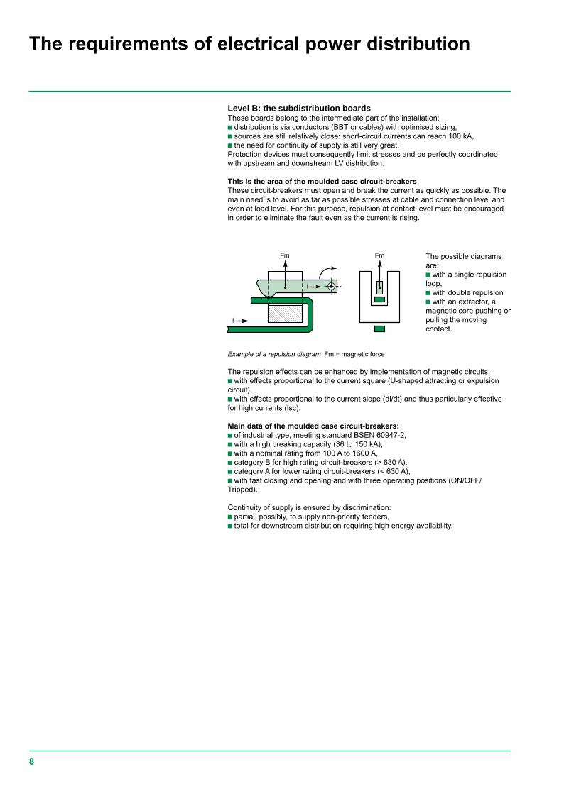
Own current compensationdiagram
Protection devices and theircoordination must be suited tothe specific features of theinstallation.c At the main switchboard, the needfor energy availability is greatest,c At the sub-distributionswitchboards, limitation of stressesin event of a fault is important,c At final distribution, user safety isessential.
1/3
2/3
i
i
A
i
ccccc Main data of these circuit-breakers:v of industrial type, meeting standard BSEN 60947-2,v with a high breaking capacity lcu from 40 to 150 kA,v with a nominal rating of 1000 to more than 5000 A,v category B:- with a high lcw from 40 kA to 100 kA — 1 s- with a high electrodynamic withstand (EDW),v with a stored energy operating mechanism allowing source coupling.Continuity of supply is ensured by total discrimination:v upstream with the protection fuses of the HV/LV transformer (*),v downstream with all the feeders (time discrimination).
(*) The value of HV/LV discrimination lies above all in the fact that resumption of operation hasfewer constraints in LV (accessibility, padlocking). This offers considerable advantages forcontinuity of supply.
These circuit-breakers are designed for high currentelectrical distribution:v they are normally installed in the MSBs to protecthigh current incomers and feeders;v they must remain closed in event of short-circuits soas to let the downstream circuit-breaker eliminate thefaults. Their operation is normally time-delayed.ElectroDynamic Withstand (EDW) and high thermalwithstand characterised by a short time withstandcurrent lcw are essential.EDW is designed to be as great as possible by an owncurrent compensation effect.
8
Level B: the subdistribution boardsThese boards belong to the intermediate part of the installation:c distribution is via conductors (BBT or cables) with optimised sizing,c sources are still relatively close: short-circuit currents can reach 100 kA,c the need for continuity of supply is still very great.Protection devices must consequently limit stresses and be perfectly coordinatedwith upstream and downstream LV distribution.
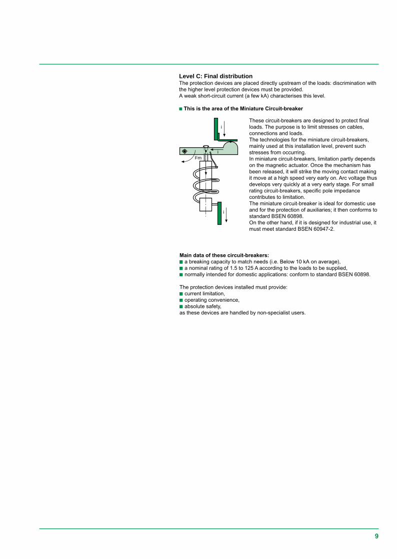
This is the area of the moulded case circuit-breakersThese circuit-breakers must open and break the current as quickly as possible. Themain need is to avoid as far as possible stresses at cable and connection level andeven at load level. For this purpose, repulsion at contact level must be encouragedin order to eliminate the fault even as the current is rising.
Fm
i
i
Fm The possible diagramsare:c with a single repulsionloop,c with double repulsionc with an extractor, amagnetic core pushing orpulling the movingcontact.
Example of a repulsion diagram Fm = magnetic force
The repulsion effects can be enhanced by implementation of magnetic circuits:c with effects proportional to the current square (U-shaped attracting or expulsioncircuit),c with effects proportional to the current slope (di/dt) and thus particularly effectivefor high currents (lsc).
Main data of the moulded case circuit-breakers:c of industrial type, meeting standard BSEN 60947-2,c with a high breaking capacity (36 to 150 kA),c with a nominal rating from 100 A to 1600 A,c category B for high rating circuit-breakers (> 630 A),c category A for lower rating circuit-breakers (< 630 A),c with fast closing and opening and with three operating positions (ON/OFF/Tripped).
Continuity of supply is ensured by discrimination:c partial, possibly, to supply non-priority feeders,c total for downstream distribution requiring high energy availability.
The requirements of electrical power distribution
9
Level C: Final distributionThe protection devices are placed directly upstream of the loads: discrimination withthe higher level protection devices must be provided.A weak short-circuit current (a few kA) characterises this level.
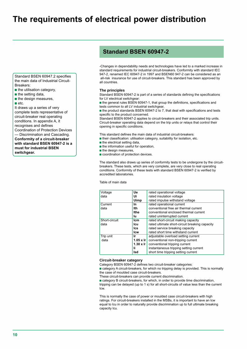
c This is the area of the Miniature Circuit-breaker
i
i
Fmi
These circuit-breakers are designed to protect finalloads. The purpose is to limit stresses on cables,connections and loads.The technologies for the miniature circuit-breakers,mainly used at this installation level, prevent suchstresses from occurring.In miniature circuit-breakers, limitation partly dependson the magnetic actuator. Once the mechanism hasbeen released, it will strike the moving contact makingit move at a high speed very early on. Arc voltage thusdevelops very quickly at a very early stage. For smallrating circuit-breakers, specific pole impedancecontributes to limitation.The miniature circuit-breaker is ideal for domestic useand for the protection of auxiliaries; it then conforms tostandard BSEN 60898.On the other hand, if it is designed for industrial use, itmust meet standard BSEN 60947-2.
Main data of these circuit-breakers:ccccc a breaking capacity to match needs (i.e. Below 10 kA on average),ccccc a nominal rating of 1.5 to 125 A according to the loads to be supplied,ccccc normally intended for domestic applications: conform to standard BSEN 60898.
The protection devices installed must provide:ccccc current limitation,ccccc operating convenience,ccccc absolute safety,as these devices are handled by non-specialist users.
10
-Changes in dependability needs and technologies have led to a marked increase instandard requirements for industrial circuit-breakers. Conformity with standard IEC947-2, renamed IEC 60947-2 in 1997 and BSEN60 947-2 can be considered as anall-risk insurance for use of circuit-breakers. This standard has been approved byall countries.
The principlesStandard BSEN 60947-2 is part of a series of standards defining the specificationsfor LV electrical switchgear:c the general rules BSEN 60947-1, that group the definitions, specifications andtests common to all LV industrial switchgear,c the product standards BSEN 60947-2 to 7, that deal with specifications and testsspecific to the product concerned.Standard BSEN 60947-2 applies to circuit-breakers and their associated trip units.Circuit-breaker operating data depend on the trip units or relays that control theiropening in specific conditions.
This standard defines the main data of industrial circuit-breakers:c their classification: utilisation category, suitability for isolation, etc.c the electrical setting data,c the information useful for operation,c the design measures,c coordination of protection devices.
The standard also draws up series of conformity tests to be undergone by the circuit-breakers. These tests, which are very complete, are very close to real operatingconditions. Conformity of these tests with standard BSEN 60947-2 is verified byaccredited laboratories.
Table of main data
Voltage Ue rated operational voltagedata Ui rated insulation voltage
Uimp rated impulse withstand voltageCurrent In rated operational currentdata Ith conventional free air thermal current
Ithe conventional enclosed thermal currentIu rated uninterrupted current
Short-circuit Icm rated short-circuit making capacitydata Icu rated ultimate short-circuit breaking capacity
Ics rated service breaking capacityIcw rated short time withstand current
Trip unit Ir adjustable overload setting current data 1.05 x Ir conventional non-tripping current
1.30 x Ir conventional tripping currentIi instantaneous tripping setting currentIsd short time tripping setting current
Circuit-breaker categoryCategory BSEN 60947-2 defines two circuit-breaker categories:c category A circuit-breakers, for which no tripping delay is provided. This is normallythe case of moulded case circuit-breakers.These circuit-breakers can provide current discrimination.c category B circuit-breakers, for which, in order to provide time discrimination,tripping can be delayed (up to 1 s) for all short-circuits of value less than the currentlcw.
This is normally the case of power or moulded case circuit-breakers with highratings. For circuit-breakers installed in the MSBs, it is important to have an lcwequal to lcu in order to naturally provide discrimination up to full ultimate breakingcapacity lcu.
Standard BSEN 60947.2 specifiesthe main data of Industrial Circuit-Breakers:c the utilisation category,c the setting data,c the design measures,c etc.It draws up a series of verycomplete tests representative ofcircuit-breaker real operatingconditions. In appendix A, itrecognises and definesCoordination of Protection Devices— Discrimination and Cascading.Conformity of a circuit-breakerwith standard BSEN 60947-2 is amust for industrial BSENswitchgear.
The requirements of electrical power distribution
Standard BSEN 60947-2
11
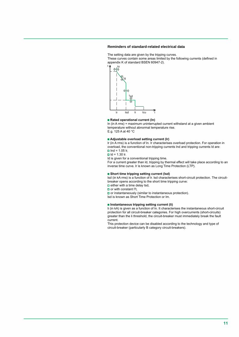
Reminders of standard-related electrical data
The setting data are given by the tripping curves.These curves contain some areas limited by the following currents (defined inappendix K of standard BSEN 60947-2).
I
t Io
IcuIr IiIsd
td
tsd
c Rated operational current (ln)ln (in A rms) = maximum uninterrupted current withstand at a given ambienttemperature without abnormal temperature rise.E.g. 125 A at 40 °C
c Adjustable overload setting current (lr)lr (in A rms) is a function of ln. lr characterises overload protection. For operation inoverload, the conventional non-tripping currents lnd and tripping currents ld are:vvvvv lnd = 1.05 lr,vvvvv ld = 1.30 lr.ld is given for a conventional tripping time.For a current greater than ld, tripping by thermal effect will take place according to aninverse time curve. lr is known as Long Time Protection (LTP).
c Short time tripping setting current (lsd)lsd (in kA rms) is a function of lr. lsd characterises short-circuit protection. The circuit-breaker opens according to the short time tripping curve:vvvvv either with a time delay tsd,vvvvv or with constant l2t,vvvvv or instantaneously (similar to instantaneous protection).lsd is known as Short Time Protection or lm.
c Instantaneous tripping setting current (li)li (in kA) is given as a function of ln. It characterises the instantaneous short-circuitprotection for all circuit-breaker categories. For high overcurrents (short-circuits)greater than the li threshold, the circuit-breaker must immediately break the faultcurrent.This protection device can be disabled according to the technology and type ofcircuit-breaker (particularly B category circuit-breakers).
12
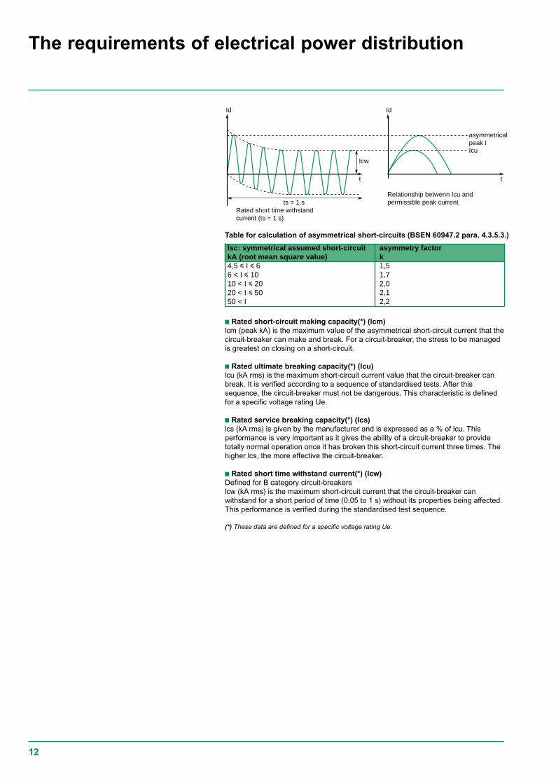
Rated short time withstandcurrent (ts = 1 s)
Relationship betwenn Icu andpermissible peak current
asymmetricalpeak I
t t
Icu
IdId
Icw
ts = 1 s
Table for calculation of asymmetrical short-circuits (BSEN 60947.2 para. 4.3.5.3.)
c Rated short-circuit making capacity(*) (lcm)lcm (peak kA) is the maximum value of the asymmetrical short-circuit current that thecircuit-breaker can make and break. For a circuit-breaker, the stress to be managedis greatest on closing on a short-circuit.
c Rated ultimate breaking capacity(*) (lcu)lcu (kA rms) is the maximum short-circuit current value that the circuit-breaker canbreak. It is verified according to a sequence of standardised tests. After thissequence, the circuit-breaker must not be dangerous. This characteristic is definedfor a specific voltage rating Ue.
c Rated service breaking capacity(*) (lcs)lcs (kA rms) is given by the manufacturer and is expressed as a % of lcu. Thisperformance is very important as it gives the ability of a circuit-breaker to providetotally normal operation once it has broken this short-circuit current three times. Thehigher lcs, the more effective the circuit-breaker.
c Rated short time withstand current(*) (lcw)Defined for B category circuit-breakerslcw (kA rms) is the maximum short-circuit current that the circuit-breaker canwithstand for a short period of time (0.05 to 1 s) without its properties being affected.This performance is verified during the standardised test sequence.
(*) These data are defined for a specific voltage rating Ue.
lsc: symmetrical assumed short-circuit asymmetry factorkA (root mean square value) k4,5 i I i 6 1,56 < I i 10 1,710 < I i 20 2,020 < I i 50 2,150 < I 2,2
The requirements of electrical power distribution
13
t
IB IcuD1
D2 D1
I
IcuD2
D1
D2
overlappingarea
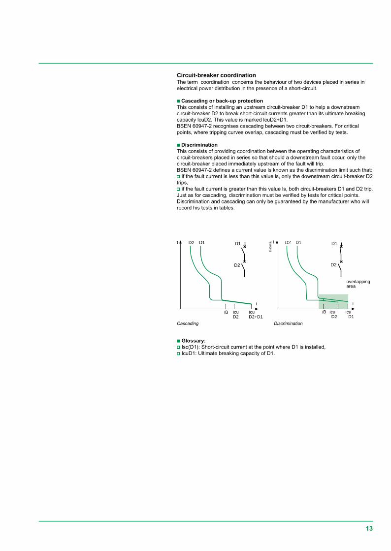
Circuit-breaker coordinationThe term coordination concerns the behaviour of two devices placed in series inelectrical power distribution in the presence of a short-circuit.
c Cascading or back-up protectionThis consists of installing an upstream circuit-breaker D1 to help a downstreamcircuit-breaker D2 to break short-circuit currents greater than its ultimate breakingcapacity lcuD2. This value is marked lcuD2+D1.BSEN 60947-2 recognises cascading between two circuit-breakers. For criticalpoints, where tripping curves overlap, cascading must be verified by tests.
c DiscriminationThis consists of providing coordination between the operating characteristics ofcircuit-breakers placed in series so that should a downstream fault occur, only thecircuit-breaker placed immediately upstream of the fault will trip.BSEN 60947-2 defines a current value ls known as the discrimination limit such that:vvvvv if the fault current is less than this value ls, only the downstream circuit-breaker D2trips,vvvvv if the fault current is greater than this value ls, both circuit-breakers D1 and D2 trip.Just as for cascading, discrimination must be verified by tests for critical points.Discrimination and cascading can only be guaranteed by the manufacturer who willrecord his tests in tables.
E 4
5015
b t
IB IcuD2+D1
D2 D1
I
IcuD2
D1
D2
Cascading Discrimination
c Glossary:vvvvv lsc(D1): Short-circuit current at the point where D1 is installed,vvvvv lcuD1: Ultimate breaking capacity of D1.
14
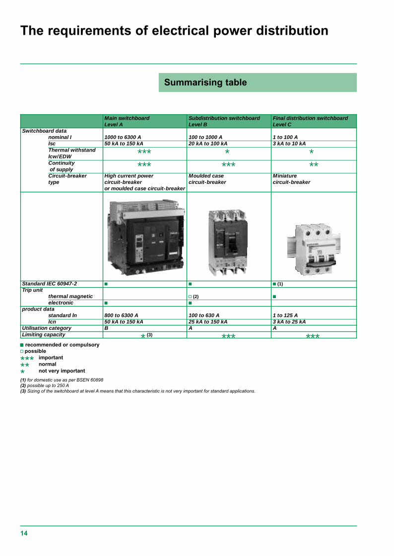
Main switchboard Subdistribution switchboard Final distribution switchboardLevel A Level B Level C
Switchboard datanominal I 1000 to 6300 A 100 to 1000 A 1 to 100 AIsc 50 kA to 150 kA 20 kA to 100 kA 3 kA to 10 kAThermal withstand *** * *lcw/EDWContinuity *** *** ** of supplyCircuit-breaker High current power Moulded case Miniaturetype circuit-breaker circuit-breaker circuit-breaker
or moulded case circuit-breaker
Standard IEC 60947-2 c c c (1)Trip unit
thermal magnetic v (2) celectronic c c
product datastandard ln 800 to 6300 A 100 to 630 A 1 to 125 AIcn 50 kA to 150 kA 25 kA to 150 kA 3 kA to 25 kA
Utilisation category B A ALimiting capacity * (3) *** ***ccccc recommended or compulsoryv possible
*** important
** normal
* not very important
(1) for domestic use as per BSEN 60898(2) possible up to 250 A(3) Sizing of the switchboard at level A means that this characteristic is not very important for standard applications.
Summarising table
The requirements of electrical power distribution
15
t
I
t
Em
t1 t2
U
L
A
ts
Id
asymmetrical
Isc
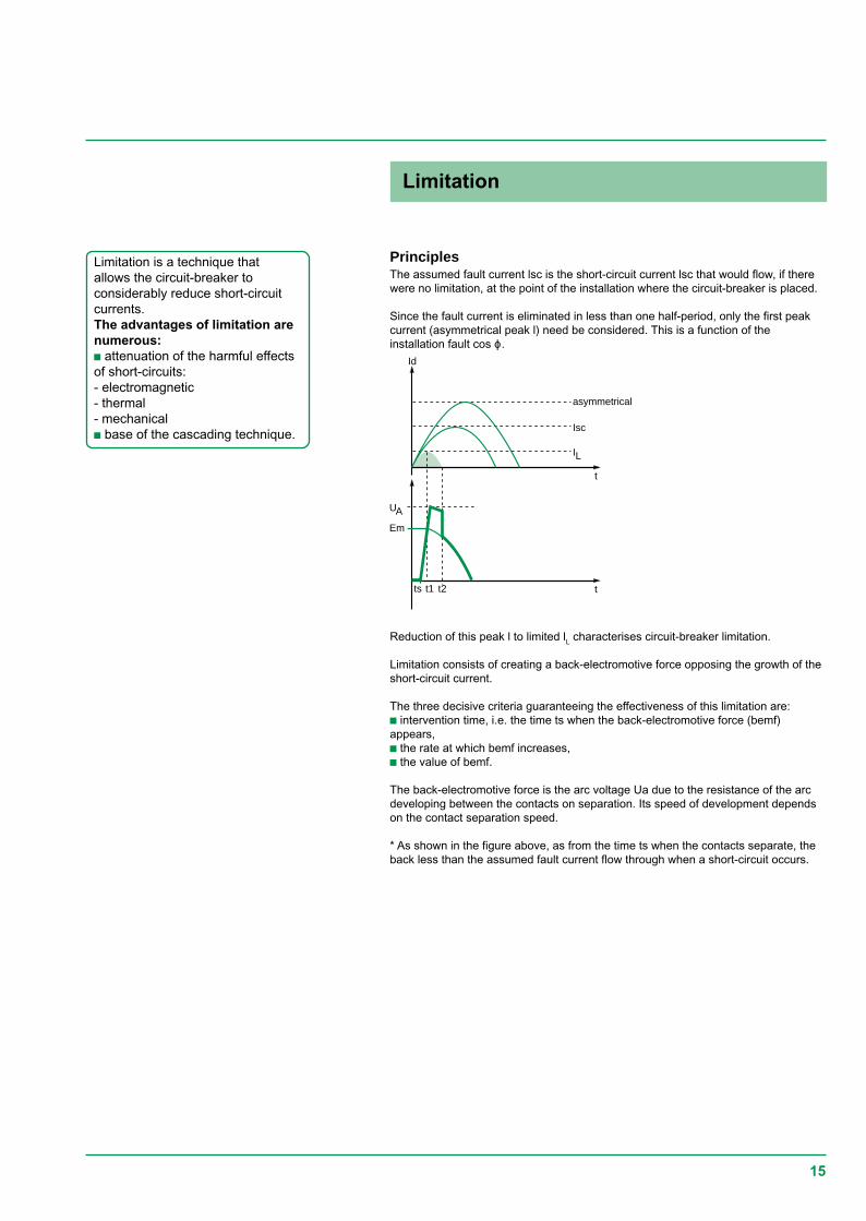
PrinciplesThe assumed fault current lsc is the short-circuit current lsc that would flow, if therewere no limitation, at the point of the installation where the circuit-breaker is placed.
Since the fault current is eliminated in less than one half-period, only the first peakcurrent (asymmetrical peak l) need be considered. This is a function of theinstallation fault cos ϕ.
Limitation is a technique thatallows the circuit-breaker toconsiderably reduce short-circuitcurrents.The advantages of limitation arenumerous:c attenuation of the harmful effectsof short-circuits:- electromagnetic- thermal- mechanicalc base of the cascading technique.
Reduction of this peak l to limited lL characterises circuit-breaker limitation.
Limitation consists of creating a back-electromotive force opposing the growth of theshort-circuit current.
The three decisive criteria guaranteeing the effectiveness of this limitation are:c intervention time, i.e. the time ts when the back-electromotive force (bemf)appears,c the rate at which bemf increases,c the value of bemf.
The back-electromotive force is the arc voltage Ua due to the resistance of the arcdeveloping between the contacts on separation. Its speed of development dependson the contact separation speed.
* As shown in the figure above, as from the time ts when the contacts separate, theback less than the assumed fault current flow through when a short-circuit occurs.
Limitation

16
A2
I2cc
t
Assumedenergy100%
Limitedenergy< 1%t
tcc
100%
10%
Âassumed transientpeak Isc
limitedpeak Isc
assumed steadypeak Isc
Isc
Advantagesc Application to electrical power distributionLimitation considerably reduces the harmful effects of short-circuits on theinstallation.harmful effects limitation effects
of short-circuitsc electromagnetic Reduction of magnetic field, thus
v less risk of disturbing neighbouringmeasurement instruments.
c mechanical Peak current limited, thus:v reduced electromagnetic forces,v less risk of deformation or breakage atelectrical contact level.
c thermal Limited thermal stress (reduction of amplitudeand duration of current flow), thus:v temperature rise of conductors less marked,v increased lifetime of busbar trunking.
Consequently, limitation contributes to the durability of electrical installations.
Circuit breaker limitation capacityThe circuit breaker limitation capacity defines the way it reduces the let throughcurrent under short-circuit conditions.
The thermal stress of the limited current is the area (shaded) defined by the curve ofthe square of the limited current l2sc (t).If there is no limitation, this stress would be the area, far larger, that would bedefined by the curve of the square of the assumed current.For an assumed short-circuit current lsc, limitation of this current to 10% results inless than 1% of assumed thermal stress.The cable temperature rise is directly proportional to the thermal stress (1).
Current and thermal stress limitation
E 4
5010
The implementation techniques
17
isolation andshort-circuitprotection
control
overloadprotectionor thermalprotection
internal motoror specificprotections
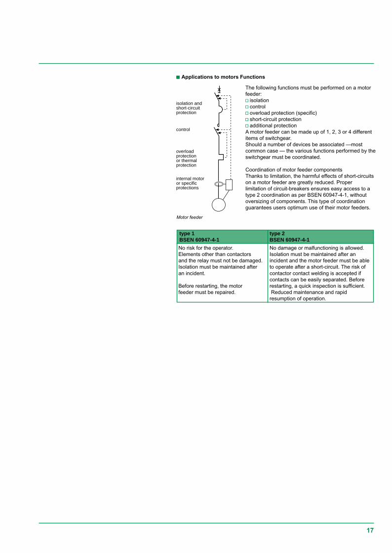
Motor feeder
ccccc Applications to motors Functions
type 1 type 2BSEN 60947-4-1 BSEN 60947-4-1
No risk for the operator. No damage or malfunctioning is allowed.Elements other than contactors Isolation must be maintained after anand the relay must not be damaged. incident and the motor feeder must be ableIsolation must be maintained after to operate after a short-circuit. The risk ofan incident. contactor contact welding is accepted if
contacts can be easily separated. BeforeBefore restarting, the motor restarting, a quick inspection is sufficient.feeder must be repaired. Reduced maintenance and rapid
resumption of operation.
The following functions must be performed on a motorfeeder:v isolationv controlv overload protection (specific)v short-circuit protectionv additional protectionA motor feeder can be made up of 1, 2, 3 or 4 differentitems of switchgear.Should a number of devices be associated —mostcommon case — the various functions performed by theswitchgear must be coordinated.
Coordination of motor feeder componentsThanks to limitation, the harmful effects of short-circuitson a motor feeder are greatly reduced. Properlimitation of circuit-breakers ensures easy access to atype 2 coordination as per BSEN 60947-4-1, withoutoversizing of components. This type of coordinationguarantees users optimum use of their motor feeders.
18
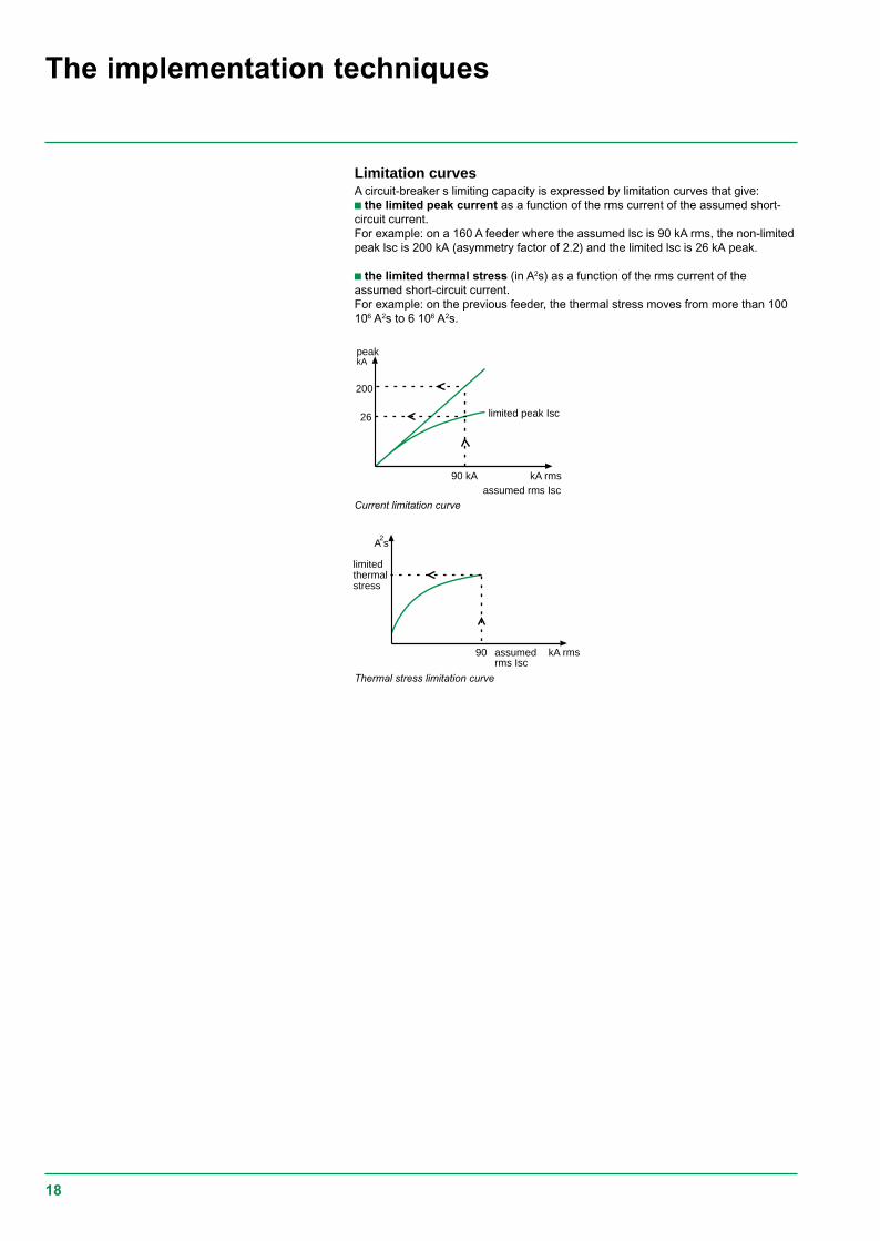
Current limitation curve
Thermal stress limitation curve
Limitation curvesA circuit-breaker s limiting capacity is expressed by limitation curves that give:c the limited peak current as a function of the rms current of the assumed short-circuit current.For example: on a 160 A feeder where the assumed lsc is 90 kA rms, the non-limitedpeak lsc is 200 kA (asymmetry factor of 2.2) and the limited lsc is 26 kA peak.
c the limited thermal stress (in A2s) as a function of the rms current of theassumed short-circuit current.For example: on the previous feeder, the thermal stress moves from more than 100106 A2s to 6 106 A2s.
The implementation techniques
kA
90 kA
200
26 limited peak Isc
assumed rms Isc
peak
kA rms
A s2
90
limitedthermalstress
assumedrms Isc
kA rms
19
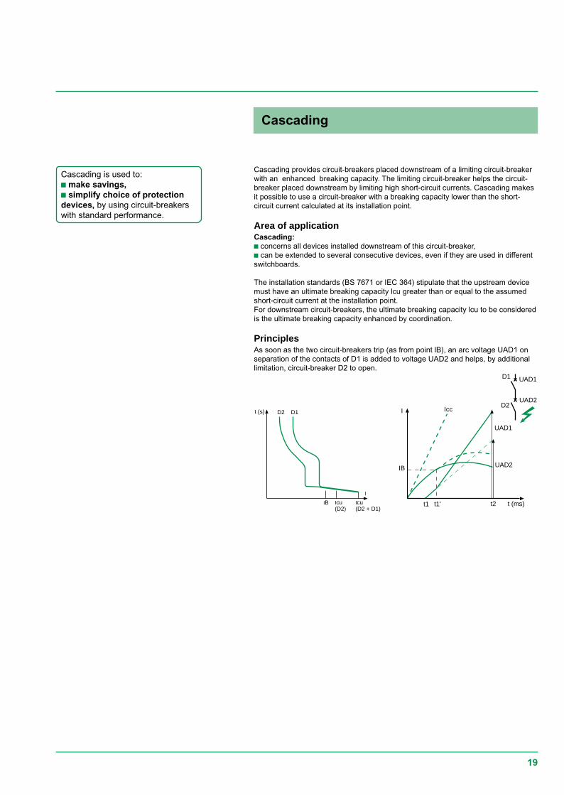
Cascading provides circuit-breakers placed downstream of a limiting circuit-breakerwith an enhanced breaking capacity. The limiting circuit-breaker helps the circuit-breaker placed downstream by limiting high short-circuit currents. Cascading makesit possible to use a circuit-breaker with a breaking capacity lower than the short-circuit current calculated at its installation point.
Area of applicationCascading:c concerns all devices installed downstream of this circuit-breaker,c can be extended to several consecutive devices, even if they are used in differentswitchboards.
The installation standards (BS 7671 or IEC 364) stipulate that the upstream devicemust have an ultimate breaking capacity lcu greater than or equal to the assumedshort-circuit current at the installation point.For downstream circuit-breakers, the ultimate breaking capacity lcu to be consideredis the ultimate breaking capacity enhanced by coordination.
PrinciplesAs soon as the two circuit-breakers trip (as from point lB), an arc voltage UAD1 onseparation of the contacts of D1 is added to voltage UAD2 and helps, by additionallimitation, circuit-breaker D2 to open.
Cascading is used to:c make savings,c simplify choice of protectiondevices, by using circuit-breakerswith standard performance.
t (s)
IB Icu(D2 + D1)
D2 D1
I
Icu(D2)
D1
D2 I
t1
Icc
UAD2IB
t1' t2
UAD1
UAD2
UAD1
t (ms)
Cascading
20
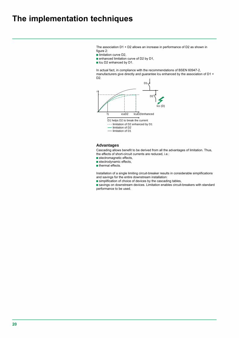
D1 helps D2 to break the currentlimitation of D2 enhanced by D1limitation of D2limitation of D1
IcuD2/enhancedIcuD2
Icc (D)
I
1I
D1
D2
The association D1 + D2 allows an increase in performance of D2 as shown infigure 2:c limitation curve D2,c enhanced limitation curve of D2 by D1,c lcu D2 enhanced by D1.
In actual fact, in compliance with the recommendations of BSEN 60947-2,manufacturers give directly and guarantee lcu enhanced by the association of D1 +D2.
AdvantagesCascading allows benefit to be derived from all the advantages of limitation. Thus,the effects of short-circuit currents are reduced, i.e.:c electromagnetic effects,c electrodynamic effects,c thermal effects.
Installation of a single limiting circuit-breaker results in considerable simplificationsand savings for the entire downstream installation:c simplification of choice of devices by the cascading tables,c savings on downstream devices. Limitation enables circuit-breakers with standardperformance to be used.
The implementation techniques
21
D1
D2
0 IsD2Ir
D1 and D2trip
I faultD2 onlytrips
I fault
Discrimination of protectiondevices is a key factor incontinuity of supply.Discrimination is:c partial,c or total,according to the characteristicsof the association of protectiondevices.The discrimination techniquesimplemented are:c currentc timec logic.Discrimination can be optimisedby use of current limitingdownstream circuit-breakers.
General information
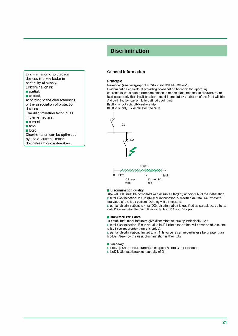
PrincipleReminder (see paragraph 1.4. "standard BSEN 60947-2").Discrimination consists of providing coordination between the operatingcharacteristics of circuit-breakers placed in series such that should a downstreamfault occur, only the circuit-breaker placed immediately upstream of the fault will trip.A discrimination current ls is defined such that:lfault > ls: both circuit-breakers trip,lfault < ls: only D2 eliminates the fault.
ccccc Discrimination qualityThe value ls must be compared with assumed lsc(D2) at point D2 of the installation.v total discrimination: ls > lsc(D2); discrimination is qualified as total, i.e. whateverthe value of the fault current, D2 only will eliminate it.v partial discrimination: ls < lsc(D2); discrimination is qualified as partial, i.e. up to ls,only D2 eliminates the fault. Beyond ls, both D1 and D2 open.
ccccc Manufacturer s dataIn actual fact, manufacturers give discrimination quality intrinsically, i.e.:v total discrimination, if ls is equal to lcuD1 (the association will never be able to seea fault current greater than this value),v partial discrimination, limited to ls. This value ls can nevertheless be greater thanlsc(D2). Seen by the user, discrimination is then total.
ccccc Glossaryv lsc(D1): Short-circuit current at the point where D1 is installed,v lcuD1: Ultimate breaking capacity of D1.
Discrimination
22
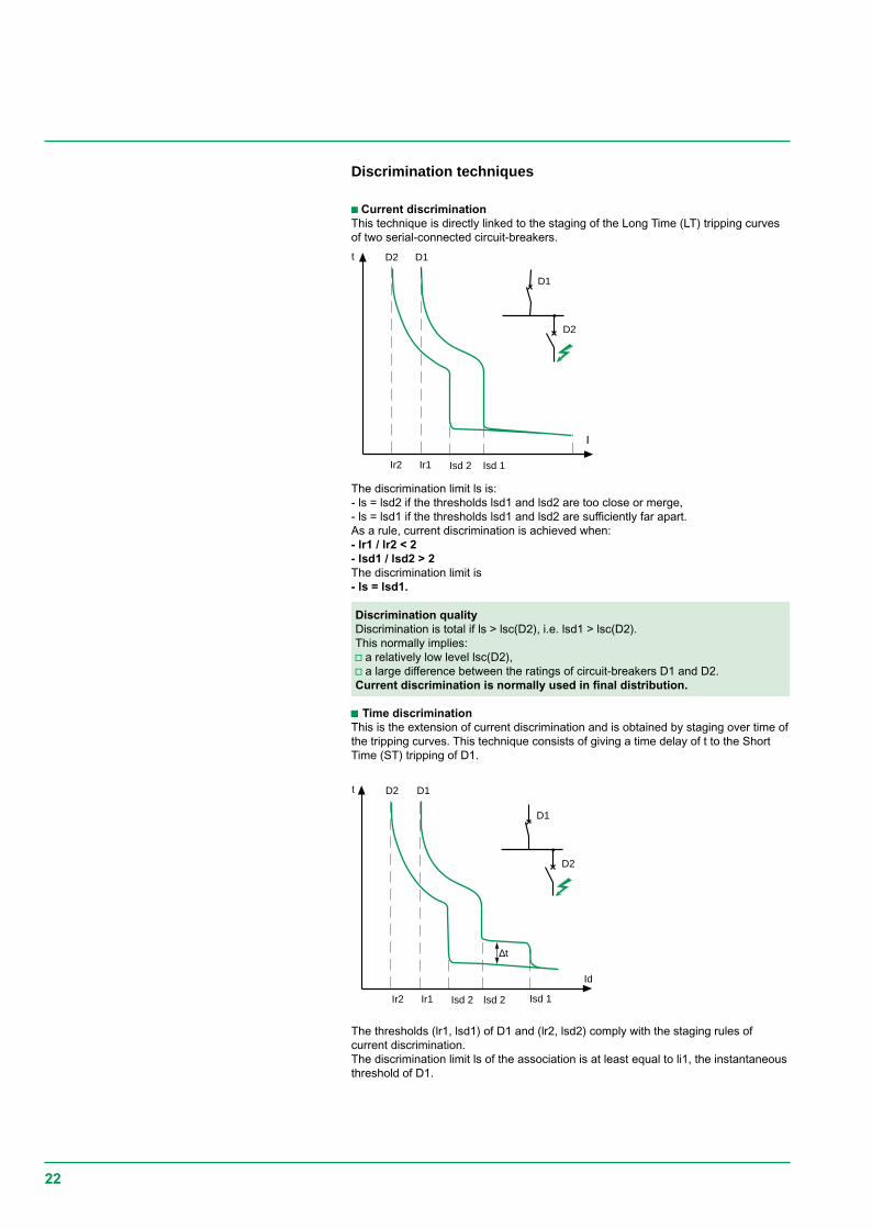
The discrimination limit ls is:- ls = lsd2 if the thresholds lsd1 and lsd2 are too close or merge,- ls = lsd1 if the thresholds lsd1 and lsd2 are sufficiently far apart.As a rule, current discrimination is achieved when:- lr1 / lr2 < 2- lsd1 / lsd2 > 2The discrimination limit is- ls = lsd1.
Discrimination qualityDiscrimination is total if ls > lsc(D2), i.e. lsd1 > lsc(D2).This normally implies:v a relatively low level lsc(D2),v a large difference between the ratings of circuit-breakers D1 and D2.Current discrimination is normally used in final distribution.
ccccc Time discriminationThis is the extension of current discrimination and is obtained by staging over time ofthe tripping curves. This technique consists of giving a time delay of t to the ShortTime (ST) tripping of D1.
Discrimination techniques
c Current discriminationThis technique is directly linked to the staging of the Long Time (LT) tripping curvesof two serial-connected circuit-breakers.
The thresholds (lr1, lsd1) of D1 and (lr2, lsd2) comply with the staging rules ofcurrent discrimination.The discrimination limit ls of the association is at least equal to li1, the instantaneousthreshold of D1.
D1
D2
Isd 2 Isd 1Ir2 Ir1
t D2 D1
I
Ir1
D1
D2
Isd 2 Isd 2Ir2 Isd 1
∆t
t D2 D1
Id
23
Ic
ILdId
Id
non-limiting
short-circuitlimiter
Isc (D2)
Discrimination qualityThere are two possible applications:c on final and/or intermediate feeders.A category circuit-breakers can be used with time-delayed tripping of theupstream circuit-breaker. This allows extension of current discrimination up to theinstantaneous threshold li1 of the upstream circuit-breaker: ls > li1.If lsc(D2) is not too high — case of a final feeder - total discrimination can beobtained.c on the incomers and feeders of the MSBAt this level, as continuity of supply takes priority, the installation characteristicsallow use of B category circuit-breakers designed for time-delayed tripping. Thesecircuit-breakers have a high thermal withstand (lcw > 50% lcn for t = 1s): ls > lcw1.Even for high lsc(D2), time discrimination normally provides totaldiscrimination: lcw1 > lsc(D2).
NB: Use of B category circuit-breakers means that the installation must withstandhigh electrodynamic and thermal stresses.Consequently, these circuit-breakers have a high instantaneous threshold li that canbe adjusted and disabled in order to protect the busbars if necessary.
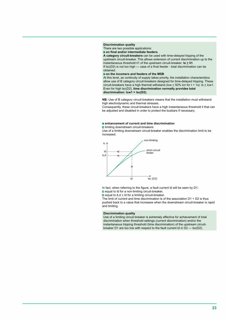
In fact, when referring to the figure, a fault current ld will be seen by D1:vvvvv equal to ld for a non-limiting circuit-breaker,vvvvv equal to lLd < ld for a limiting circuit-breaker.The limit of current and time discrimination ls of the association D1 + D2 is thuspushed back to a value that increases when the downstream circuit-breaker is rapidand limiting.
Discrimination qualityUse of a limiting circuit-breaker is extremely effective for achievement of totaldiscrimination when threshold settings (current discrimination) and/or theinstantaneous tripping threshold (time discrimination) of the upstream circuit-breaker D1 are too low with respect to the fault current ld in D2 — lsc(D2).
c enhancement of current and time discriminationvvvvv limiting downstream circuit-breakersUse of a limiting downstream circuit-breaker enables the discrimination limit to beincreased.
24
D1
D2
D3
pilot wire
interlockingorder
interlockingorder
The implementation techniques
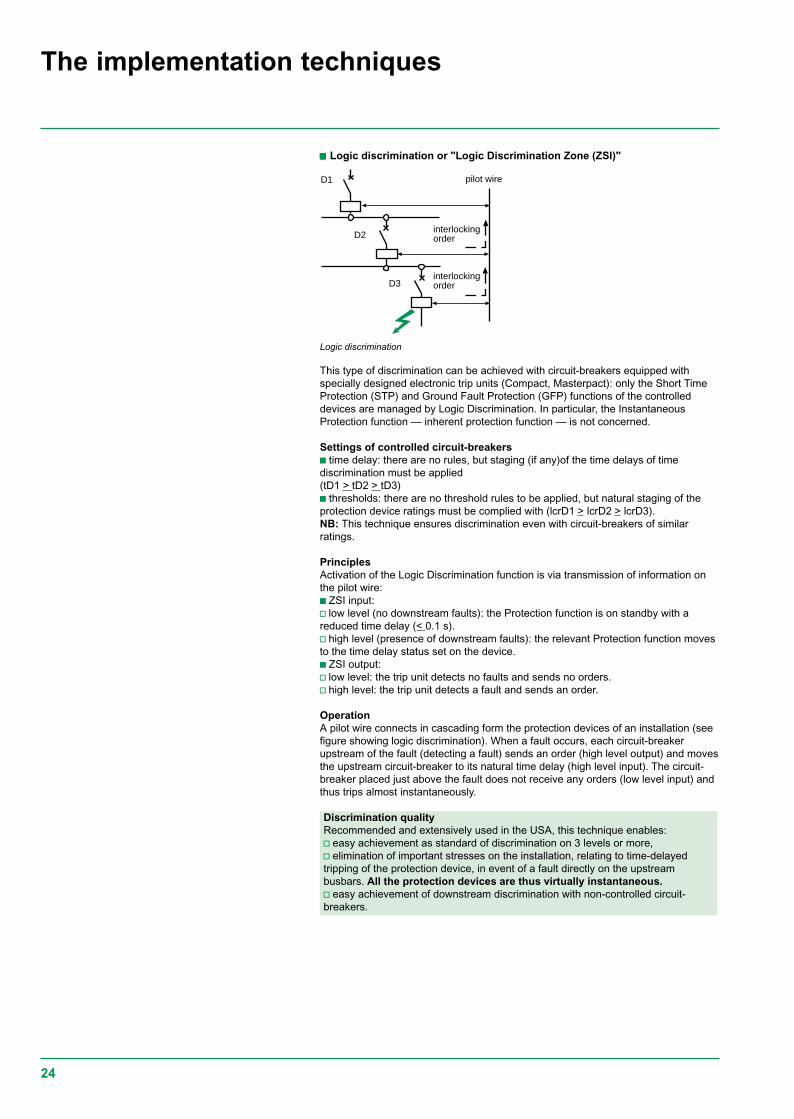
This type of discrimination can be achieved with circuit-breakers equipped withspecially designed electronic trip units (Compact, Masterpact): only the Short TimeProtection (STP) and Ground Fault Protection (GFP) functions of the controlleddevices are managed by Logic Discrimination. In particular, the InstantaneousProtection function — inherent protection function — is not concerned.
Settings of controlled circuit-breakersc time delay: there are no rules, but staging (if any)of the time delays of timediscrimination must be applied(tD1 > tD2 > tD3)c thresholds: there are no threshold rules to be applied, but natural staging of theprotection device ratings must be complied with (lcrD1 > lcrD2 > lcrD3).NB: This technique ensures discrimination even with circuit-breakers of similarratings.
PrinciplesActivation of the Logic Discrimination function is via transmission of information onthe pilot wire:c ZSI input:v low level (no downstream faults): the Protection function is on standby with areduced time delay (< 0.1 s).v high level (presence of downstream faults): the relevant Protection function movesto the time delay status set on the device.c ZSI output:v low level: the trip unit detects no faults and sends no orders.v high level: the trip unit detects a fault and sends an order.
OperationA pilot wire connects in cascading form the protection devices of an installation (seefigure showing logic discrimination). When a fault occurs, each circuit-breakerupstream of the fault (detecting a fault) sends an order (high level output) and movesthe upstream circuit-breaker to its natural time delay (high level input). The circuit-breaker placed just above the fault does not receive any orders (low level input) andthus trips almost instantaneously.
Discrimination qualityRecommended and extensively used in the USA, this technique enables:v easy achievement as standard of discrimination on 3 levels or more,v elimination of important stresses on the installation, relating to time-delayedtripping of the protection device, in event of a fault directly on the upstreambusbars. All the protection devices are thus virtually instantaneous.v easy achievement of downstream discrimination with non-controlled circuit-breakers.
Logic discrimination
ccccc Logic discrimination or "Logic Discrimination Zone (ZSI)"
25
Isd1
t
Icu D2
Is
Isd1
D1
D2
Ir2
I t2
I
ND
D
Is
D1D2
IIr2 currentdiscrimination
timediscrimination
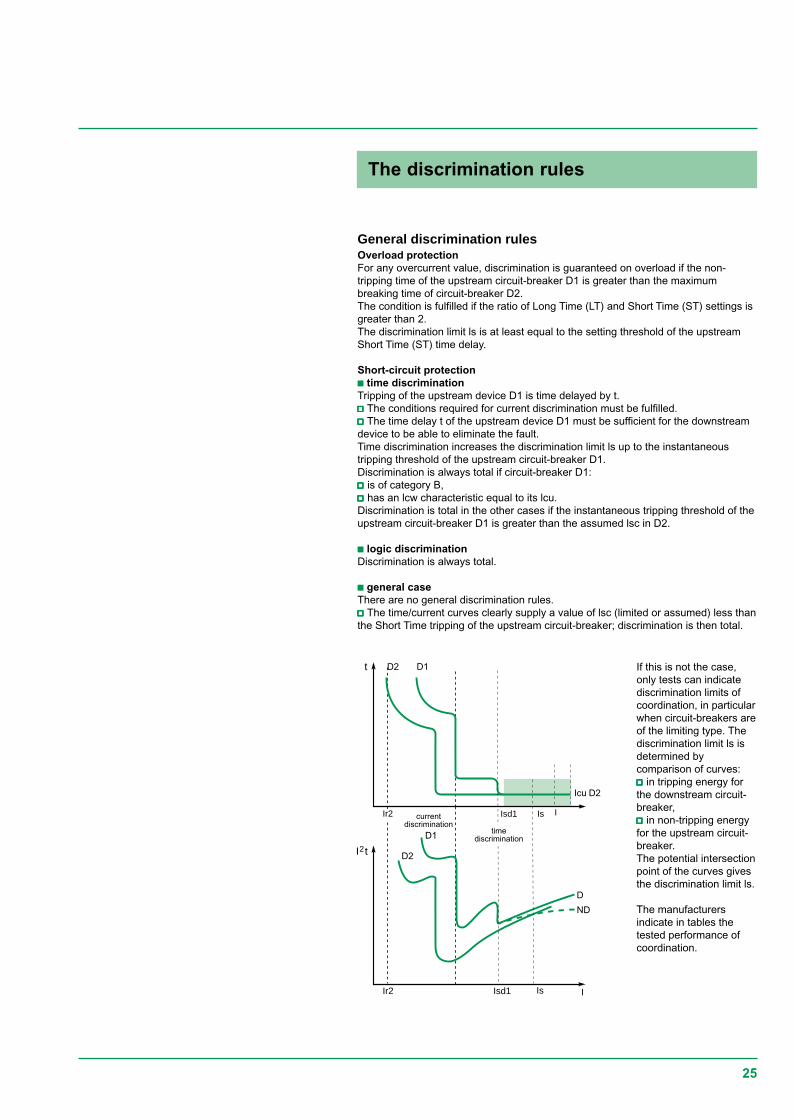
General discrimination rulesOverload protectionFor any overcurrent value, discrimination is guaranteed on overload if the non-tripping time of the upstream circuit-breaker D1 is greater than the maximumbreaking time of circuit-breaker D2.The condition is fulfilled if the ratio of Long Time (LT) and Short Time (ST) settings isgreater than 2.The discrimination limit ls is at least equal to the setting threshold of the upstreamShort Time (ST) time delay.
Short-circuit protectionc time discriminationTripping of the upstream device D1 is time delayed by t.vvvvv The conditions required for current discrimination must be fulfilled.vvvvv The time delay t of the upstream device D1 must be sufficient for the downstreamdevice to be able to eliminate the fault.Time discrimination increases the discrimination limit ls up to the instantaneoustripping threshold of the upstream circuit-breaker D1.Discrimination is always total if circuit-breaker D1:vvvvv is of category B,vvvvv has an lcw characteristic equal to its lcu.Discrimination is total in the other cases if the instantaneous tripping threshold of theupstream circuit-breaker D1 is greater than the assumed lsc in D2.
c logic discriminationDiscrimination is always total.
c general caseThere are no general discrimination rules.vvvvv The time/current curves clearly supply a value of lsc (limited or assumed) less thanthe Short Time tripping of the upstream circuit-breaker; discrimination is then total.
If this is not the case,only tests can indicatediscrimination limits ofcoordination, in particularwhen circuit-breakers areof the limiting type. Thediscrimination limit ls isdetermined bycomparison of curves:vvvvv in tripping energy forthe downstream circuit-breaker,vvvvv in non-tripping energyfor the upstream circuit-breaker.The potential intersectionpoint of the curves givesthe discrimination limit ls.
The manufacturersindicate in tables thetested performance ofcoordination.
The discrimination rules
26
According to the Earthing System, discrimination only uses coordination ofovercurrent protection devices. When the insulation fault is treated specifically byearth leakage protection devices (e.g. in the TT system), discrimination of theresidual current devices (RCDs) with one another must also be guaranteed.
Discrimination of earth leakage protection devices must ensure that, should aninsulation fault occur, only the feeder concerned by the fault is de-energised.The aim is to optimise energy availability.
There are two types of earth leakage protection discrimination.
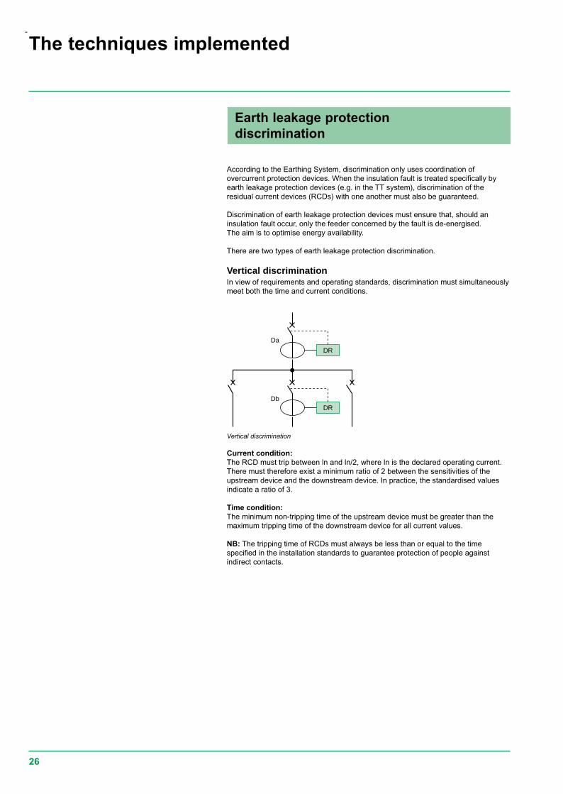
Vertical discriminationIn view of requirements and operating standards, discrimination must simultaneouslymeet both the time and current conditions.
Vertical discrimination
DR
DR
Da
Db
Current condition:The RCD must trip between ln and ln/2, where ln is the declared operating current.There must therefore exist a minimum ratio of 2 between the sensitivities of theupstream device and the downstream device. In practice, the standardised valuesindicate a ratio of 3.
Time condition:The minimum non-tripping time of the upstream device must be greater than themaximum tripping time of the downstream device for all current values.
NB: The tripping time of RCDs must always be less than or equal to the timespecified in the installation standards to guarantee protection of people againstindirect contacts.
The techniques implemented
Earth leakage protectiondiscrimination
-
27
10
20
50100
200
500
tms
1 2 5 10
500 A
Id / I∆n.
G
S max.
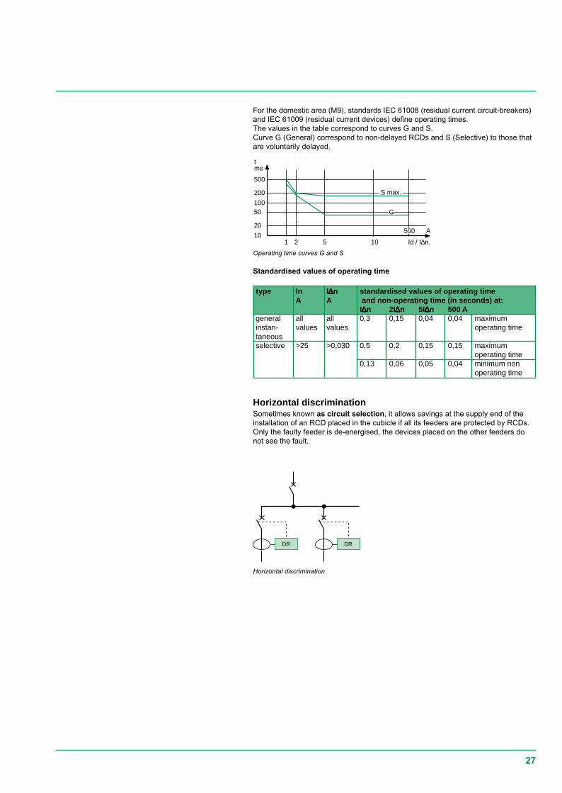
Standardised values of operating time
type In I∆∆∆∆∆n standardised values of operating timeA A and non-operating time (in seconds) at:
I∆∆∆∆∆n 2I∆∆∆∆∆n 5I∆∆∆∆∆n 500 Ageneral all all 0,3 0,15 0,04 0,04 maximuminstan- values values operating timetaneousselective >25 >0,030 0,5 0,2 0,15 0,15 maximum
operating time0,13 0,06 0,05 0,04 minimum non
operating time
Horizontal discrimination
Operating time curves G and S
For the domestic area (M9), standards IEC 61008 (residual current circuit-breakers)and IEC 61009 (residual current devices) define operating times.The values in the table correspond to curves G and S.Curve G (General) correspond to non-delayed RCDs and S (Selective) to those thatare voluntarily delayed.
DR DR
Horizontal discriminationSometimes known as circuit selection, it allows savings at the supply end of theinstallation of an RCD placed in the cubicle if all its feeders are protected by RCDs.Only the faulty feeder is de-energised, the devices placed on the other feeders donot see the fault.
28
Installation standard IEC 364 governs electrical installations of buildings. BS7671 theBritish National standard, based on this IEC standard, recommend goodcoordination between the protection switchgear. They acknowledge the principles ofcascading and discrimination of circuit-breakers based on product standardBSEN 60947-2.
c Product standards BSEN 60947-2In appendix A, standard BSEN 60947-2 recognises and defines coordinationbetween circuit-breakers (see paragraph 1.4 page 11). In particular, it defines thetests to be performed.vvvvv discriminationThis is normally studied on a theoretical level. For critical points where trippingcurves overlap, it must be verified by tests. It is guaranteed by the manufacturer whowill record the value of ls (discrimination limit) in tables.vvvvv cascading or coordination of the back-up protection deviceThe standard indicates the measurements to be taken to verify this coordination.- Verification by comparison of characteristicsIn practical cases, this type of verification is sufficient. It must be clearly proved thatthe lcuD2 of the association is compatible with the maximum energy l2t acceptableby D2.- Verification by testsCascading is normally verified by tests for critical points. The tests are performedwith an upstream circuit-breaker D1 with a maximum overcurrent setting and adownstream circuit-breaker D2 with a minimum setting. The test results (breakingcapacities enhanced by cascading) are in a table and guaranteed by themanufacturer.
c Installation standardsBS 7671 national installation standards specify the implementation of theseprinciples as per the Earthing System considered, in accordance with standardIEC 364.
DiscriminationDiscrimination is defined and established for all Earthing Systems used andtypes of fault (overload, short-circuit, insulation fault). However, in event of aninsulation fault in the IT system, the advantage of continuity of supply is provided bythe actual system that tolerates the 1st fault. This advantage must be maintained by asearch and rapid elimination of this fault.
CascadingOn the other hand, cascading rules are given for a TN or TT type earthingsystem.
Basic rules in TT system:Cascading rules cannot apply for an IT system due to the double insulation fault. Thefollowing rules must be implemented:vvvvv the circuit-breaker must have a breaking capacity that is greater than or equal tothe three-phase short-circuit current at the point considered,vvvvv in event of a assumed double fault, it is laid down that the double fault short-circuitcurrent will be at most:- 15% of three-phase lsc for a three- phase lsc < 10 000 A,- 25% of three-phase lsc for a three-phase lsc > 10 000 A.
Coordination of protection devices andinstallation standards
Discrimination and cascading canonly be guaranteed by themanufacturer who will record histests in tables.
The techniques implemented
29
L1L2L3N
PE
L1L2L3NPE
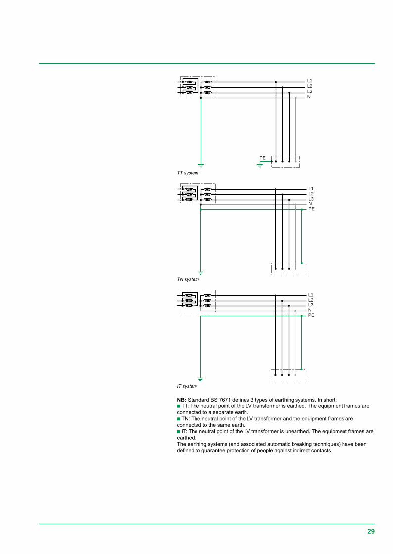
NB: Standard BS 7671 defines 3 types of earthing systems. In short:c TT: The neutral point of the LV transformer is earthed. The equipment frames areconnected to a separate earth.c TN: The neutral point of the LV transformer and the equipment frames areconnected to the same earth.c IT: The neutral point of the LV transformer is unearthed. The equipment frames areearthed.The earthing systems (and associated automatic breaking techniques) have beendefined to guarantee protection of people against indirect contacts.
L1L2L3NPE
IT system
TN system
TT system
30
The Merlin Gerin and Telemecanique circuit-breaker ranges cover all therequirements of LV electrical power distribution from 0.5 to 6300 A, i.e.:c the Merlin Gerin 630 to 6300 A Masterpact and power circuit-breaker ranges,c the range of Compact moulded case circuit-breakers (MCCB):v Compact CM from 1250 to 3200 A,v Compact C from 800 to 1250 A,v Compact NS from 100 to 630 A,c the 0.5 to 125 A Multi 9 NG125, C60, DPN miniature circuit-breaker ranges,c the Telemecanique Integral/GV2/GV7 motor protection circuit-breaker ranges.
These products meet product standards BSEN 60947-2.
The Merlin Gerin and Telemecanique distribution and motor protection circuit-breakerranges have been developed coherently. Their coordination has been tested as perBSEN 60947-2 and is guaranteed by Schneider Electric. The complete tables givingcoordination, cascading and discrimination of circuit-breakers are available.
Range of circuit breakers
31
For power circuit-breakers
The technologies of Merlin Gerin Masterpact range ideally meets the discriminationneeds at the supply end of the installation as well as specific limitation requirementsrelating to certain applications.
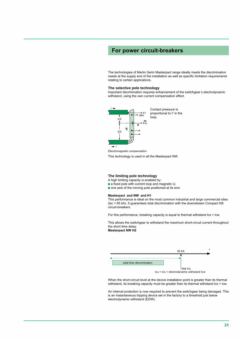
The selective pole technologyImportant discrimination requires enhancement of the switchgear s electrodynamicwithstand, using the own current compensation effect.
Contact pressure isproportional to l2 in theloop.
This technology is used in all the Masterpact NW.
The limiting pole technologyA high limiting capacity is enabled by:c a fixed pole with current loop and magnetic U,c one axis of the moving pole positioned at its end.
Masterpact and NW and H1This performance is ideal on the most common industrial and large commercial sites(lsc < 65 kA). It guarantees total discrimination with the downstream Compact NScircuit-breakers.
For this performance, breaking capacity is equal to thermal withstand lcs = lcw.
This allows the switchgear to withstand the maximum short-circuit current throughoutthe short time delay.Masterpact NW H2
Electromagnetic compensation
1/3
2/3
i
iA
i
Frdfm
Fm
When the short-circuit level at the device installation point is greater than its thermalwithstand, its breaking capacity must be greater than its thermal withstand lcs > lcw.
An internal protection is now required to prevent the switchgear being damaged. Thisis an instantaneous tripping device set in the factory to a threshold just belowelectrodynamic withstand (EDW).
I65 kA
NW H1
total time discrimination
Icu = Ics = electrodynamic withstand Icw
32
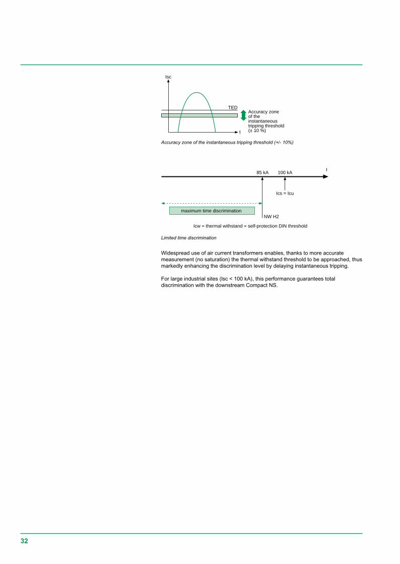
TED
t
Isc
Accuracy zoneof theinstantaneoustripping threshold(± 10 %)
85 kAI
100 kA
Ics = Icu
NW H2
Icw = thermal withstand = self-protection DIN threshold
maximum time discrimination
Accuracy zone of the instantaneous tripping threshold (+/- 10%)
Limited time discrimination
Widespread use of air current transformers enables, thanks to more accuratemeasurement (no saturation) the thermal withstand threshold to be approached, thusmarkedly enhancing the discrimination level by delaying instantaneous tripping.
For large industrial sites (lsc < 100 kA), this performance guarantees totaldiscrimination with the downstream Compact NS.
33
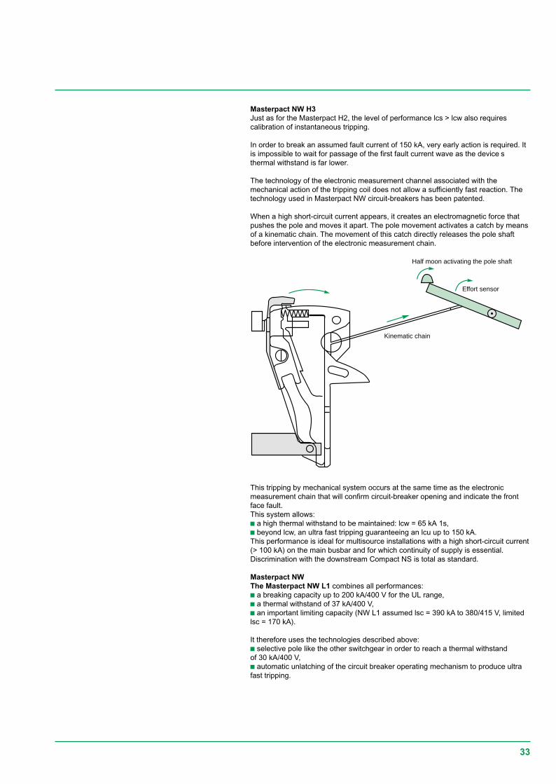
Half moon activating the pole shaft
Effort sensor
Kinematic chain
Masterpact NW H3Just as for the Masterpact H2, the level of performance lcs > lcw also requirescalibration of instantaneous tripping.
In order to break an assumed fault current of 150 kA, very early action is required. Itis impossible to wait for passage of the first fault current wave as the device sthermal withstand is far lower.
The technology of the electronic measurement channel associated with themechanical action of the tripping coil does not allow a sufficiently fast reaction. Thetechnology used in Masterpact NW circuit-breakers has been patented.
When a high short-circuit current appears, it creates an electromagnetic force thatpushes the pole and moves it apart. The pole movement activates a catch by meansof a kinematic chain. The movement of this catch directly releases the pole shaftbefore intervention of the electronic measurement chain.
This tripping by mechanical system occurs at the same time as the electronicmeasurement chain that will confirm circuit-breaker opening and indicate the frontface fault.This system allows:c a high thermal withstand to be maintained: lcw = 65 kA 1s,c beyond lcw, an ultra fast tripping guaranteeing an lcu up to 150 kA.This performance is ideal for multisource installations with a high short-circuit current(> 100 kA) on the main busbar and for which continuity of supply is essential.Discrimination with the downstream Compact NS is total as standard.
Masterpact NWThe Masterpact NW L1 combines all performances:c a breaking capacity up to 200 kA/400 V for the UL range,c a thermal withstand of 37 kA/400 V,c an important limiting capacity (NW L1 assumed lsc = 390 kA to 380/415 V, limitedlsc = 170 kA).
It therefore uses the technologies described above:c selective pole like the other switchgear in order to reach a thermal withstandof 30 kA/400 V,c automatic unlatching of the circuit breaker operating mechanism to produce ultrafast tripping.
34
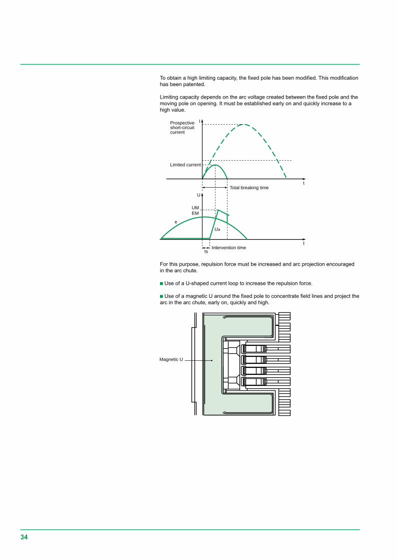
Magnetic U
t
t
UM
ts
I
U
EM
Ua
e
Prospectiveshort-circuitcurrent
Limited current
Total breaking time
Intervention time
To obtain a high limiting capacity, the fixed pole has been modified. This modificationhas been patented.
Limiting capacity depends on the arc voltage created between the fixed pole and themoving pole on opening. It must be established early on and quickly increase to ahigh value.
For this purpose, repulsion force must be increased and arc projection encouragedin the arc chute.
c Use of a U-shaped current loop to increase the repulsion force.
c Use of a magnetic U around the fixed pole to concentrate field lines and project thearc in the arc chute, early on, quickly and high.
35
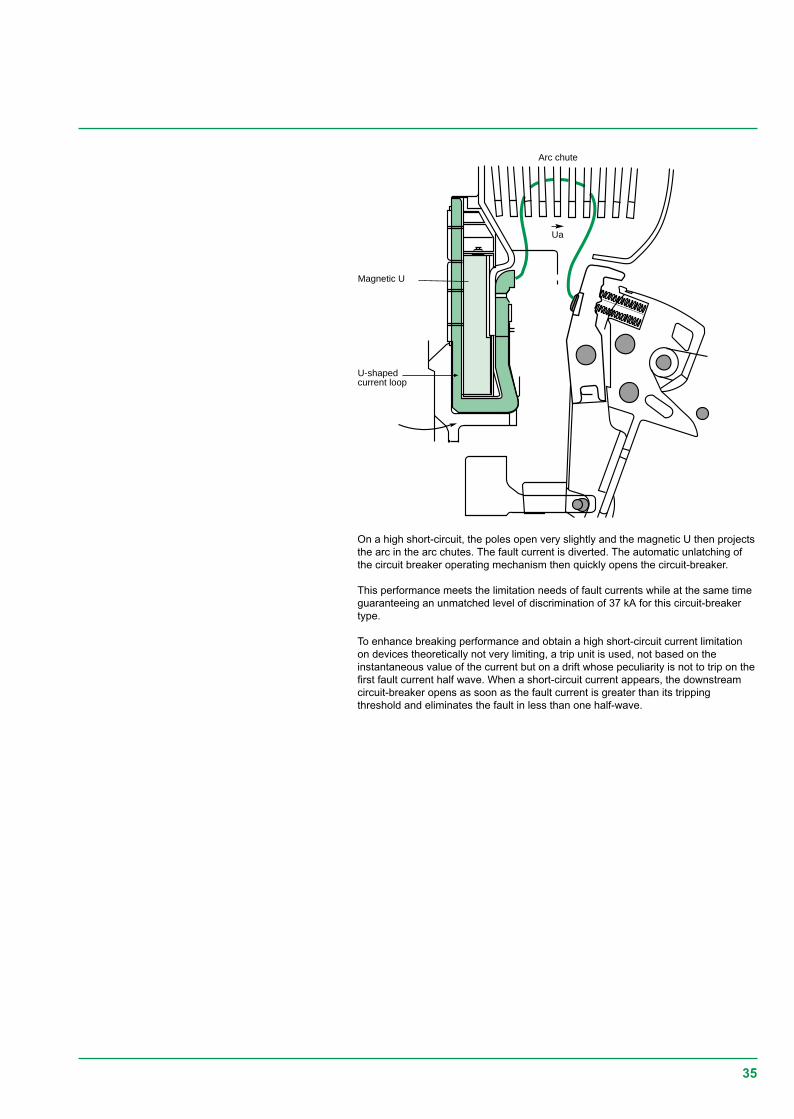
Ua
Arc chute
Magnetic U
U-shapedcurrent loop
On a high short-circuit, the poles open very slightly and the magnetic U then projectsthe arc in the arc chutes. The fault current is diverted. The automatic unlatching ofthe circuit breaker operating mechanism then quickly opens the circuit-breaker.
This performance meets the limitation needs of fault currents while at the same timeguaranteeing an unmatched level of discrimination of 37 kA for this circuit-breakertype.
To enhance breaking performance and obtain a high short-circuit current limitationon devices theoretically not very limiting, a trip unit is used, not based on theinstantaneous value of the current but on a drift whose peculiarity is not to trip on thefirst fault current half wave. When a short-circuit current appears, the downstreamcircuit-breaker opens as soon as the fault current is greater than its trippingthreshold and eliminates the fault in less than one half-wave.
36
Arc chute
Short-circuitcurrent
PistonArc
Arc
Fixedcontact
Movingcontact
Arc chute
Breakingenclosure
Arc chute
Fixedcontact
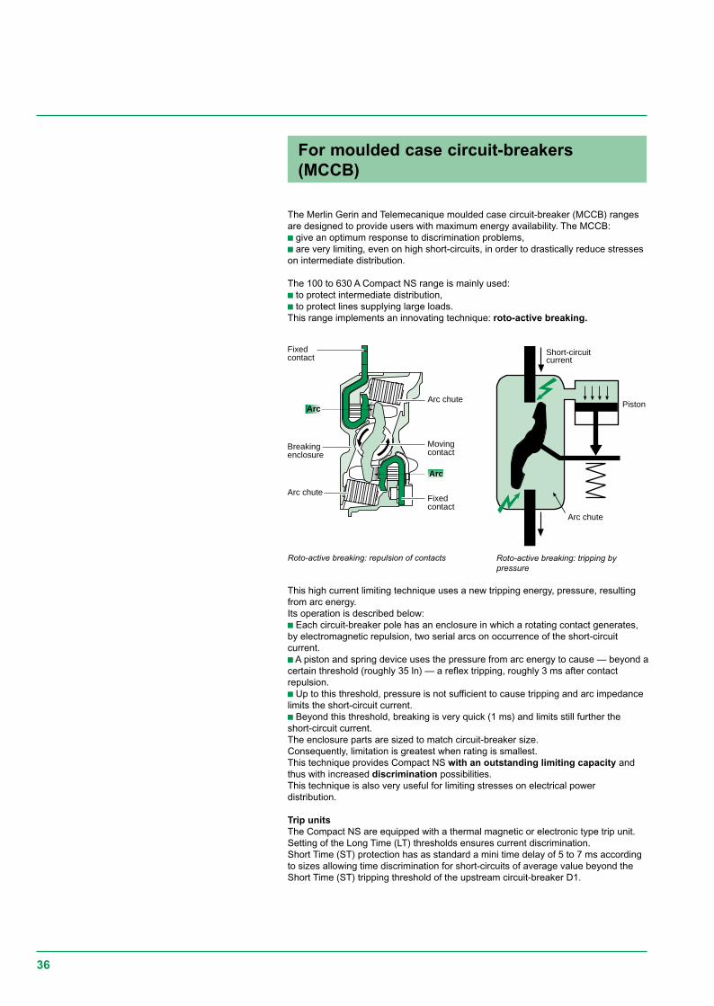
The Merlin Gerin and Telemecanique moulded case circuit-breaker (MCCB) rangesare designed to provide users with maximum energy availability. The MCCB:c give an optimum response to discrimination problems,c are very limiting, even on high short-circuits, in order to drastically reduce stresseson intermediate distribution.
The 100 to 630 A Compact NS range is mainly used:c to protect intermediate distribution,c to protect lines supplying large loads.This range implements an innovating technique: roto-active breaking.
This high current limiting technique uses a new tripping energy, pressure, resultingfrom arc energy.Its operation is described below:c Each circuit-breaker pole has an enclosure in which a rotating contact generates,by electromagnetic repulsion, two serial arcs on occurrence of the short-circuitcurrent.c A piston and spring device uses the pressure from arc energy to cause — beyond acertain threshold (roughly 35 ln) — a reflex tripping, roughly 3 ms after contactrepulsion.c Up to this threshold, pressure is not sufficient to cause tripping and arc impedancelimits the short-circuit current.c Beyond this threshold, breaking is very quick (1 ms) and limits still further theshort-circuit current.The enclosure parts are sized to match circuit-breaker size.Consequently, limitation is greatest when rating is smallest.This technique provides Compact NS with an outstanding limiting capacity andthus with increased discrimination possibilities.This technique is also very useful for limiting stresses on electrical powerdistribution.
Trip unitsThe Compact NS are equipped with a thermal magnetic or electronic type trip unit.Setting of the Long Time (LT) thresholds ensures current discrimination.Short Time (ST) protection has as standard a mini time delay of 5 to 7 ms accordingto sizes allowing time discrimination for short-circuits of average value beyond theShort Time (ST) tripping threshold of the upstream circuit-breaker D1.
For moulded case circuit-breakers(MCCB)
Roto-active breaking: repulsion of contacts Roto-active breaking: tripping bypressure
37
For miniature circuit-breakers
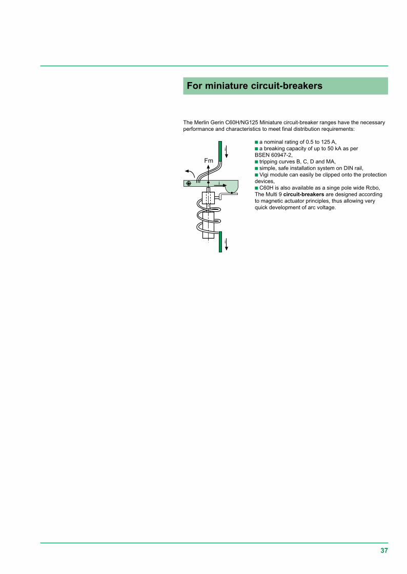
The Merlin Gerin C60H/NG125 Miniature circuit-breaker ranges have the necessaryperformance and characteristics to meet final distribution requirements:
Fm
i
i
i
c a nominal rating of 0.5 to 125 A,c a breaking capacity of up to 50 kA as perBSEN 60947-2,c tripping curves B, C, D and MA,c simple, safe installation system on DIN rail,c Vigi module can easily be clipped onto the protectiondevices,c C60H is also available as a singe pole wide Rcbo,The Multi 9 circuit-breakers are designed accordingto magnetic actuator principles, thus allowing veryquick development of arc voltage.
38
D1
100 kA
NW20 H2
D2
l=20 m
60 kA
NW40 H2
Busbar
Total discrimination
D1
D2
NW20 H2
100 kABusbar
Discrimination limited to 86 kA
General discrimination rules (in distribution)c Overload protectionvvvvv upstream and downstream circuit-breakers equipped with a thermal magnetic tripunit.The current discrimination of Merlin Gerin and Telemecanique circuit-breakers isprovided if the ratio of the tripping thresholds:- thermal is greater than 1.6- magnetic is greater than 2.vvvvv upstream circuit-breaker equipped with an electronic trip unit and downstream .circuit-breaker equipped with a thermal magnetic trip unit.Current discrimination of the Merlin Gerin and Telemecanique circuit-breakers isprovided if the ratio of the tripping thresholds:- Long Time (LT) and thermal is greater than 1.6(*) to 2.5,- Short Time (ST) and magnetic is greater than 1.5.vvvvv upstream and downstream circuit-breakers equipped with an electronic trip unit.Current discrimination of the Merlin Gerin and Telemecanique circuit-breakers isprovided if the ratio of the tripping thresholds:- Long Time (LT) is greater than 1.2(*) to 1.6,- Short Time (ST) is greater than 1.5.(*) Upstream trip unit equipped with a time-delayable LT threshold.
c Short-circuit protectionv time discriminationTime discrimination of Merlin Gerin and Telemecanique circuit-breakers is providedas soon as there is a difference of one time delay band between the upstream andthe downstream device.v logic discriminationDiscrimination is always total.
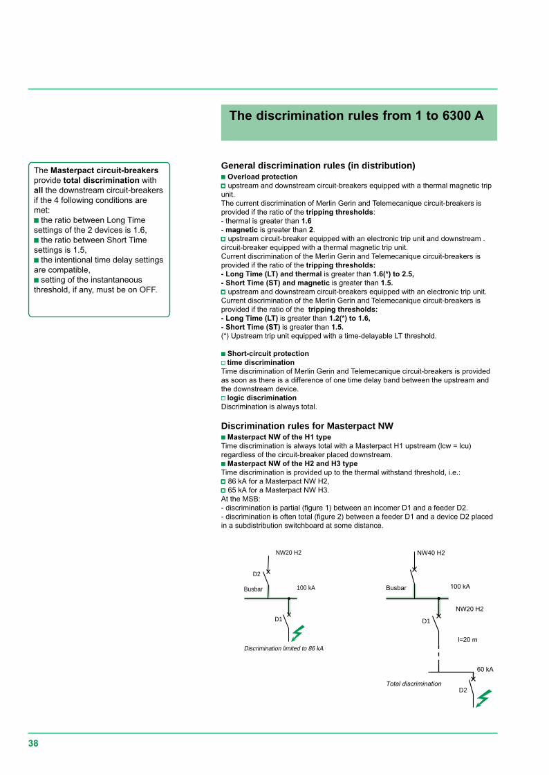
Discrimination rules for Masterpact NWc Masterpact NW of the H1 typeTime discrimination is always total with a Masterpact H1 upstream (lcw = lcu)regardless of the circuit-breaker placed downstream.c Masterpact NW of the H2 and H3 typeTime discrimination is provided up to the thermal withstand threshold, i.e.:vvvvv 86 kA for a Masterpact NW H2,vvvvv 65 kA for a Masterpact NW H3.At the MSB:- discrimination is partial (figure 1) between an incomer D1 and a feeder D2.- discrimination is often total (figure 2) between a feeder D1 and a device D2 placedin a subdistribution switchboard at some distance.
The Masterpact circuit-breakersprovide total discrimination withall the downstream circuit-breakersif the 4 following conditions aremet:c the ratio between Long Timesettings of the 2 devices is 1.6,c the ratio between Short Timesettings is 1.5,c the intentional time delay settingsare compatible,c setting of the instantaneousthreshold, if any, must be on OFF.
The discrimination rules from 1 to 6300 A
39
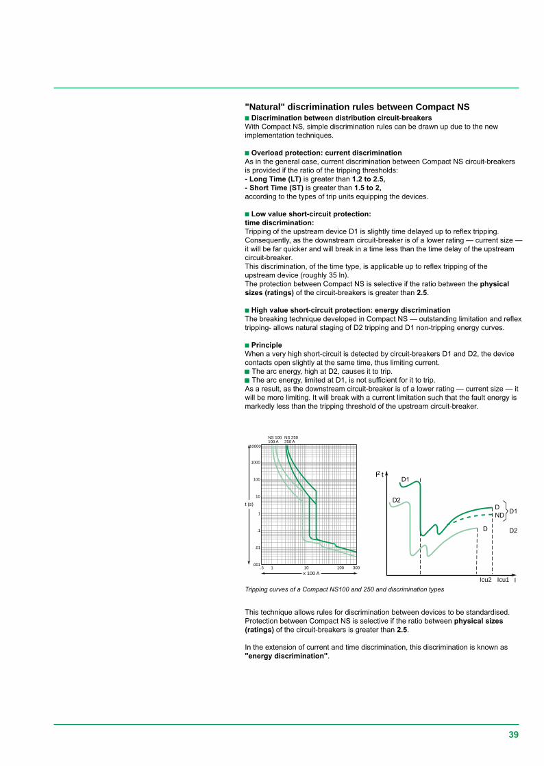
Tripping curves of a Compact NS100 and 250 and discrimination types
"Natural" discrimination rules between Compact NSc Discrimination between distribution circuit-breakersWith Compact NS, simple discrimination rules can be drawn up due to the newimplementation techniques.
c Overload protection: current discriminationAs in the general case, current discrimination between Compact NS circuit-breakersis provided if the ratio of the tripping thresholds:- Long Time (LT) is greater than 1.2 to 2.5,- Short Time (ST) is greater than 1.5 to 2,according to the types of trip units equipping the devices.
c Low value short-circuit protection:time discrimination:Tripping of the upstream device D1 is slightly time delayed up to reflex tripping.Consequently, as the downstream circuit-breaker is of a lower rating — current size —it will be far quicker and will break in a time less than the time delay of the upstreamcircuit-breaker.This discrimination, of the time type, is applicable up to reflex tripping of theupstream device (roughly 35 ln).The protection between Compact NS is selective if the ratio between the physicalsizes (ratings) of the circuit-breakers is greater than 2.5.
c High value short-circuit protection: energy discriminationThe breaking technique developed in Compact NS — outstanding limitation and reflextripping- allows natural staging of D2 tripping and D1 non-tripping energy curves.
c PrincipleWhen a very high short-circuit is detected by circuit-breakers D1 and D2, the devicecontacts open slightly at the same time, thus limiting current.ccccc The arc energy, high at D2, causes it to trip.ccccc The arc energy, limited at D1, is not sufficient for it to trip.As a result, as the downstream circuit-breaker is of a lower rating — current size — itwill be more limiting. It will break with a current limitation such that the fault energy ismarkedly less than the tripping threshold of the upstream circuit-breaker.
D1
D2
I t2
Icu1
NDD
Icu2
D
D1
D2
Ix 100 A
t (s)
10000
NS 100100 A
NS 250250 A
1000
100
10
1
.1
.01
.001.5 1 10 100 300
This technique allows rules for discrimination between devices to be standardised.Protection between Compact NS is selective if the ratio between physical sizes(ratings) of the circuit-breakers is greater than 2.5.
In the extension of current and time discrimination, this discrimination is known as"energy discrimination".
40
D1
D2
I t2
Icu1
NDD
Icu2
D1RC
D D2
Currentdiscrimination
Timediscrimination
Energydisrimination
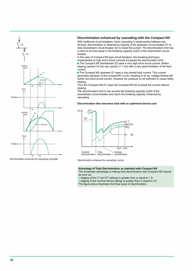
Discrimination enhanced by cascading with the Compact NSWith traditional circuit-breakers, when cascading is implemented between twodevices, discrimination is obtained by tripping of the upstream circuit-breaker D1 tohelp downstream circuit-breaker D2 to break the current. The discrimination limit hasa value ls at most equal to the breaking capacity lcuD2 of the downstream circuit-breaker.In the case of Compact NS type circuit-breakers, the breaking techniqueimplemented on high short-circuit currents increases the discrimination limit.c The Compact NS downstream D2 sees a very high short-circuit current. Reflextripping causes it to trip very quickly (< 1 ms) with a very great limitation of the faultcurrent.c The Compact NS upstream D1 sees a very limited fault current. This currentgenerates repulsion of the contacts/RC curve, resulting in an arc voltage limiting stillfurther the short-circuit current. However arc pressure is not sufficient to cause reflextripping.Thus the Compact NS D1 helps the Compact NS D2 to break the current withouttripping.The discrimination limit ls can exceed the breaking capacity lcuD2 of thedownstream circuit-breaker and reach the breaking capacity enhanced bycascading.
Discrimination then becomes total with an optimised device cost
UA D2
UA D1
D1
D1
D2
D2ID/IN2
PD2
ID/IN1
t
t
t
t
ts t's
PD1
ts
ts t's
Reflexe
Reflexe
Discrimination enhanced by cascading: principle Discrimination enhanced by cascading: curves
Advantage of Total Discrimination as standard with Compact NSThe immediate advantage is making total discrimination with Compact NS naturalas soon as:v staging of the LT and ST settings is greater than or equal to 1.5,v staging of the nominal device ratings is greater than or equal to 2.5.The figure above illustrates the three types of discrimination.
41
D1 application D2 ratio between the upstream and downstream settingsthermal protection magnetic protectionupstream lr / downstream lr upstream lm / downstream lm
TM…D Distribution TM…D u 1,6 u 2STR…SE/GE u 1,6 u 1,5
Motor MA + separate thermal relay u 3 u 2motor thermal magnetic u 3 u 2STR…ME u 3 u 1,5
STR…2 or 3 Distribution TM…D u 2,5 u 1,5fixed LT time delay STR…SE/GE u 1,6 u 1,5
Motor MA + separate thermal relay u 3 u 1,5motor thermal magnetic u 3 u 1,5STR…ME u 3 u 1,5
Micrologic 2.0, 5.0, 6.0 and 7.0 Distribution TM…D u 1,6 u 1,5STR...4, 5 or 6 STR…SE/GE, Micrologic u 1,2 u 1,5adjustable LT time delay Motor MA + separate thermal relay u 3 u 1,5shifted on the upper band motor thermal magnetic u 3 u 1,5with respect to the downstream STR…ME, Micrologic u 3 u 1,5protection
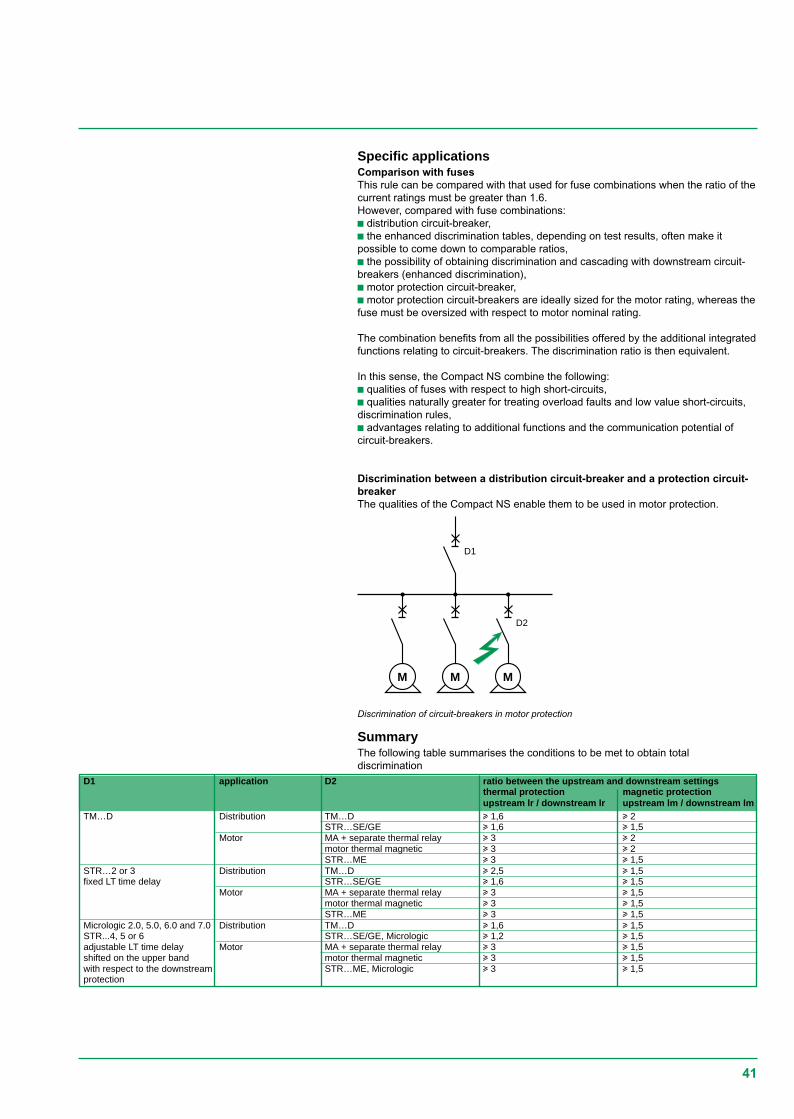
Discrimination of circuit-breakers in motor protection
M
D2
MM
D1
Specific applicationsComparison with fusesThis rule can be compared with that used for fuse combinations when the ratio of thecurrent ratings must be greater than 1.6.However, compared with fuse combinations:c distribution circuit-breaker,c the enhanced discrimination tables, depending on test results, often make itpossible to come down to comparable ratios,c the possibility of obtaining discrimination and cascading with downstream circuit-breakers (enhanced discrimination),c motor protection circuit-breaker,c motor protection circuit-breakers are ideally sized for the motor rating, whereas thefuse must be oversized with respect to motor nominal rating.
The combination benefits from all the possibilities offered by the additional integratedfunctions relating to circuit-breakers. The discrimination ratio is then equivalent.
In this sense, the Compact NS combine the following:c qualities of fuses with respect to high short-circuits,c qualities naturally greater for treating overload faults and low value short-circuits,discrimination rules,c advantages relating to additional functions and the communication potential ofcircuit-breakers.
Discrimination between a distribution circuit-breaker and a protection circuit-breakerThe qualities of the Compact NS enable them to be used in motor protection.
SummaryThe following table summarises the conditions to be met to obtain totaldiscrimination
42
The tables in section 3 show the discrimination possibilities of the Merlin Gerincircuit-breakers with one another.Depending on whether or not there is cascading, the results come from acomparison of characteristics or tests.
Conditions of useConditions of use are specified: circuit-breakers can be used in distribution or motorprotection.
Reading the tablesThe shaded boxes and boxes containing a "T" correspond to total discriminationbetween the relevant upstream and downstream circuit-breakersunder all faultconditions.For the other boxes, discrimination is either partial (indicated discrimination limit) orthere is no discrimination (boxes with no value mentioned).
Tables of discrimination enhanced by cascading with Compact NSWith Compact NS type circuit-breakers, the cascading implemented between twodevices increases the discrimination limit.This can consequently reach the breaking capacity enhanced by cascading anddiscrimination then becomes total.This is expressed in enhanced discrimination tables with these circuit-breakerssee page 45.
Discrimination tables
The tables in section 3 give,in 220/240 V and 400/415 V phase-to-phase distributionand then in motor protection, the cascading possibilities according to BSEN 60947-2between circuit-breakers:c Multi 9 with Multi 9,c Compact NS, Compact, Masterpact with Multi 9 and with one another.For circuit-breakers used in single-phase on a TN system, the 220/240 V table isused.
NB: The cascading tables are given for an earthing system of the TN or TT type.They do not apply to the IT systems.
Case of several parallel-connected transformersIn this case, specific tables must be used which give the types of circuit-breaker tobe installed on the source feeders and on the main feeders in the case of 2 or 3parallel-connected transformers.They are drawn up with the following assumptions:c short-circuit power of the upstream network of 500 MVA,c coupled transformers are identical (20 kV/410 V) and have a standard short-circuitvoltage,c the short-circuit current on the busbar does not allow for link impedances (mostunfavourable case),c the conditions for parallel-connecting of transformers are met, i.e. the transformershave:v the same Usc,v the same ratio,v a ratio of powers < 2.lsc is given for information, it may vary according to the Usc as a % given by thetransformer manufacturers. The values of the breaking capacities enhanced bycascading are thus given for higher values.
Cascading tables
Implementation of discrimination and cascading
43
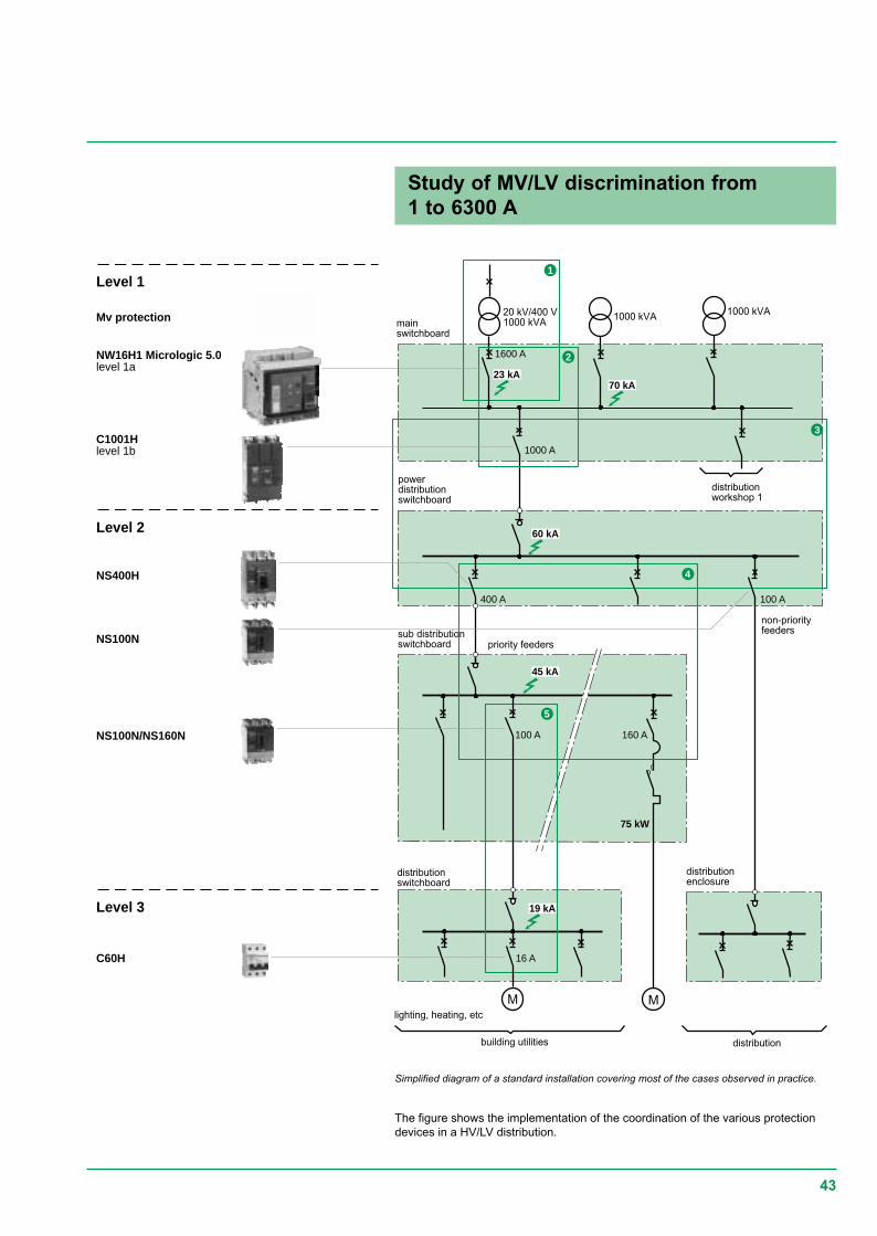
Study of MV/LV discrimination from1 to 6300 A
Simplified diagram of a standard installation covering most of the cases observed in practice.
The figure shows the implementation of the coordination of the various protectiondevices in a HV/LV distribution.
Level 1
Level 2
Level 3
NW16H1 Micrologic 5.0level 1a
NS400H
C1001Hlevel 1b
powerdistributionswitchboard
distributionswitchboard
mainswitchboard
sub distributionswitchboardNS100N
Mv protection
non-priorityfeeders
distributionenclosure
distribution
lighting, heating, etc
building utilities
1000 kVA
1000 A
M M
100 A400 A
100 A 160 A
75 kW
16 A
20 kV/400 V1000 kVA
1600 A
1000 kVA
19 kA
45 kA
60 kA
23 kA70 kA
C60H
NS100N/NS160N
1
2
3
4
5
distributionworkshop 1
priority feeders
44
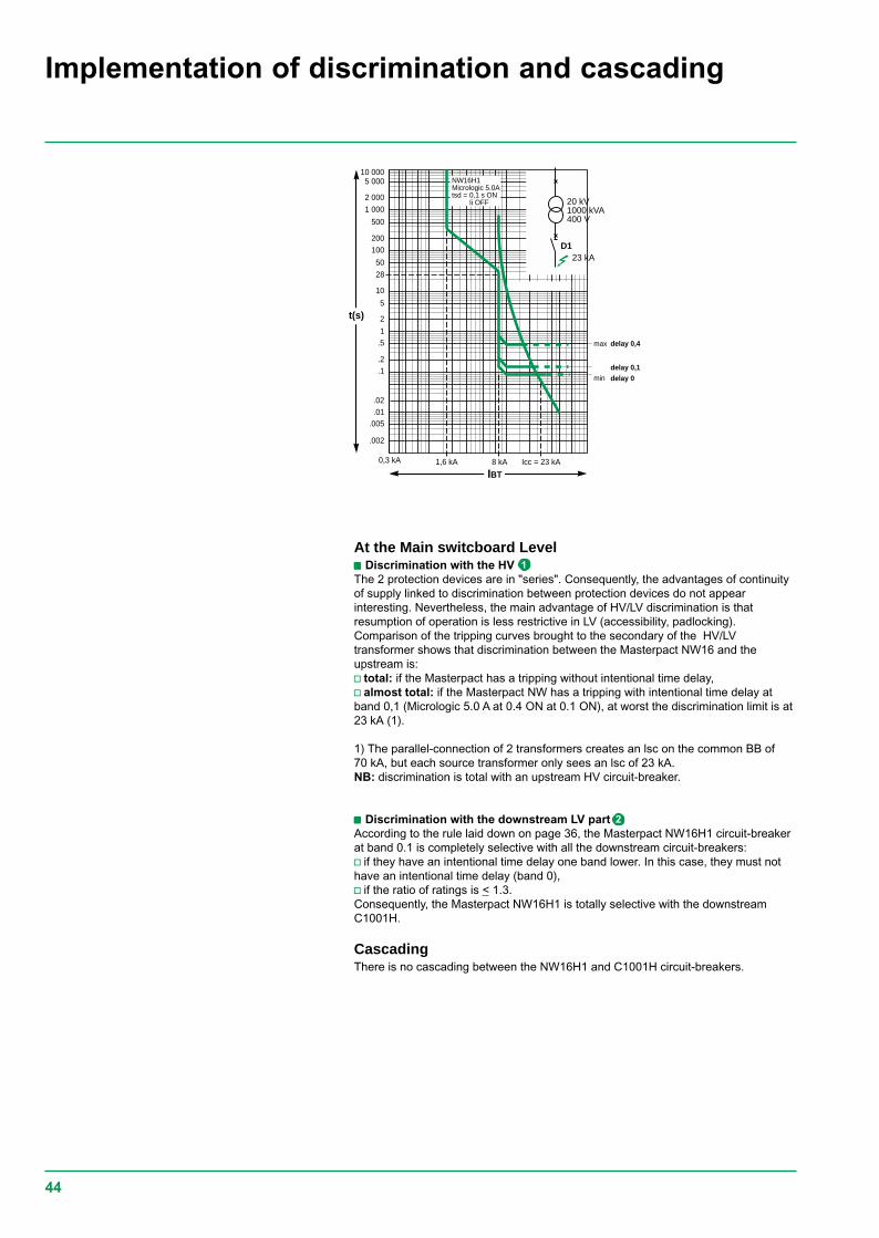
At the Main switcboard Levelccccc Discrimination with the HVThe 2 protection devices are in "series". Consequently, the advantages of continuityof supply linked to discrimination between protection devices do not appearinteresting. Nevertheless, the main advantage of HV/LV discrimination is thatresumption of operation is less restrictive in LV (accessibility, padlocking).Comparison of the tripping curves brought to the secondary of the HV/LVtransformer shows that discrimination between the Masterpact NW16 and theupstream is:v total: if the Masterpact has a tripping without intentional time delay,v almost total: if the Masterpact NW has a tripping with intentional time delay atband 0,1 (Micrologic 5.0 A at 0.4 ON at 0.1 ON), at worst the discrimination limit is at23 kA (1).
1) The parallel-connection of 2 transformers creates an lsc on the common BB of70 kA, but each source transformer only sees an lsc of 23 kA.NB: discrimination is total with an upstream HV circuit-breaker.
ccccc Discrimination with the downstream LV partAccording to the rule laid down on page 36, the Masterpact NW16H1 circuit-breakerat band 0.1 is completely selective with all the downstream circuit-breakers:v if they have an intentional time delay one band lower. In this case, they must nothave an intentional time delay (band 0),v if the ratio of ratings is < 1.3.Consequently, the Masterpact NW16H1 is totally selective with the downstreamC1001H.
CascadingThere is no cascading between the NW16H1 and C1001H circuit-breakers.
Implementation of discrimination and cascading
1
2
10 0005 000
2 000
1 000
500
200100
50
28
10
5
2
1.5
.2
.005
.002
0,3 kA 1,6 kA 8 kA
t(s)
IBTIcc = 23 kA
NW16H1Micrologic 5.0Atsd = 0,1 s ON
Ii OFF
.01
.02
.1min
max delay 0,4
delay 0,1delay 0
D123 kA
F1
20 kV1000 kVA400 V
45
At the power distribution switchboardc Cascading between the C1001H and the NS400/NS100, by enhancing thebreaking capacity of the NS, enables use of N type NS.c The discrimination tables show that use of N type NS circuit-breakers is "totallyselective" with the C1001H. This discrimination is limited to the intrinsic breakingcapacity of the downstream device, i.e. respectively 25 kA for the NS100Nand 45 kA for the NS400N.
At installation level (figure on page 41), the NS100 supplies non-priority feeders.Consequently, implementation of a Compact NS100 of the N type ensuringdiscrimination up to 25 kA is an optimised protection solution.On the other hand, the NS400 supplies loads requiring a high electrical poweravailability. Total discrimination for the user, i.e. up to the assumed lsc level, isnecessary. An H type NS400 must then be installed, that provides this performancedue to the very great limiting capacity of this circuit-breaker.
At the subdistribution switchboardDownstream of the NS400H circuit-breaker, coordination with the NS160N circuit-breaker is provided thanks to enhanced cascading:c with enhancement of breaking capacity of the NS160N (up to 70 kA),c enhancement of discrimination (up to the enhanced breaking capacity of NS160N,i.e. 70 kA).Discrimination is total.
Motor protection circuit-breakerCoordination with upstream distributionThe motor power (75 kA) requires at 400 V a protection by an NS160 MA circuit-breaker set at 150 A. Coordination performance is identical to that established fordistribution protection, i.e.c enhancement of breaking capacity of the NS160 MA,c with enhancement of discrimination (up to the enhanced breaking capacity ofNS160 MA, i.e. 70 kA).
Coordination at motor feeder levelThe limiting qualities of the NS160 circuit-breaker results in a type 2 coordinationwith standard components: Telemecanique contactors and thermal protection relay.This coordination is guaranteed by Schneider Electric.
NB: Protection by fuse results in oversizing of the motor feeder components toobtain a type 2 coordination.
At the final distribution switchboardDespite the lsc level, at this point of the installation, coordination performancebetween the Compact NS and M9 ranges ensures total discrimination using astandard C60H.
Total discrimination of this installation was provided between:c HV and LV,c on 5 stages of LV distribution
Schneider Electric also provides a software to assist with defining circuit-breakers,Ecodial. It optimises choice of circuit-breakers and their settings according to theinstallation type.
3
4
5
46
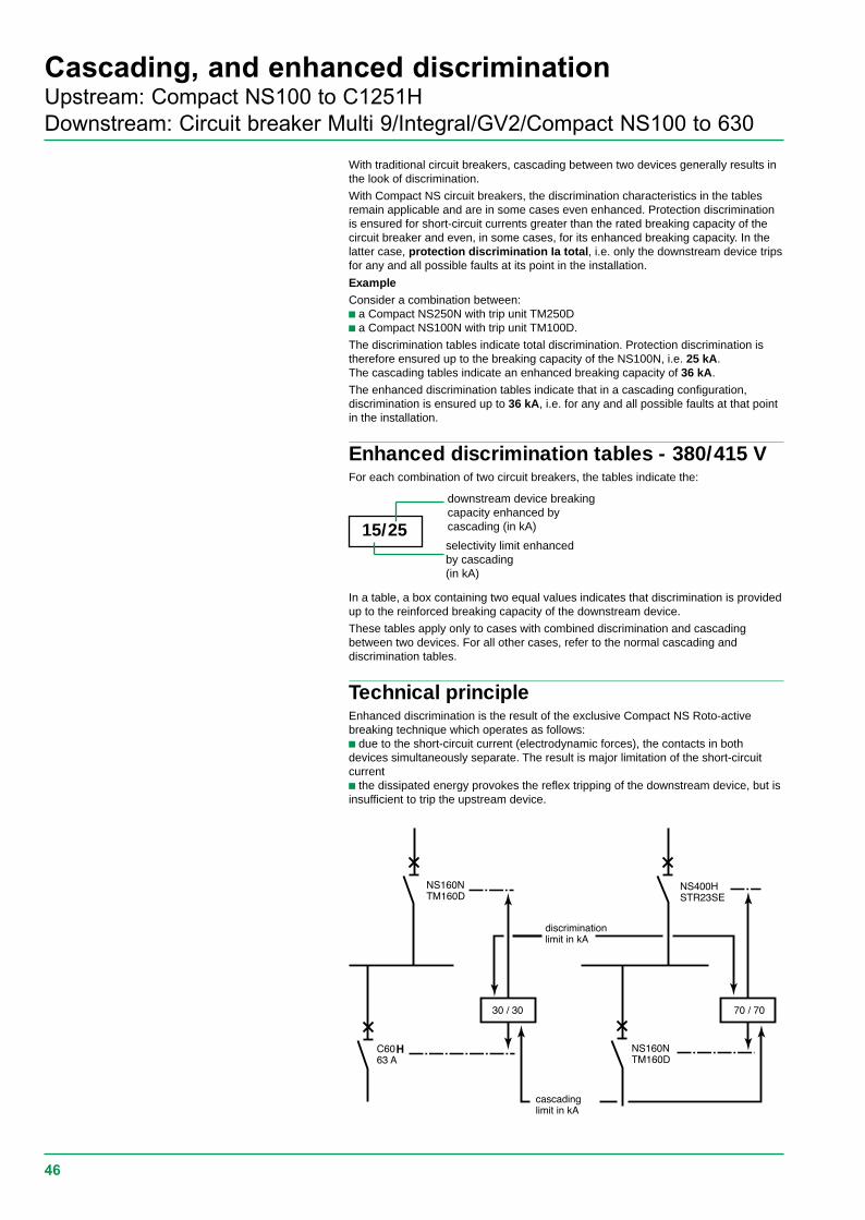
Cascading, and enhanced discriminationUpstream: Compact NS100 to C1251HDownstream: Circuit breaker Multi 9/Integral/GV2/Compact NS100 to 630
With traditional circuit breakers, cascading between two devices generally results inthe look of discrimination.
With Compact NS circuit breakers, the discrimination characteristics in the tablesremain applicable and are in some cases even enhanced. Protection discriminationis ensured for short-circuit currents greater than the rated breaking capacity of thecircuit breaker and even, in some cases, for its enhanced breaking capacity. In thelatter case, protection discrimination Ia total, i.e. only the downstream device tripsfor any and all possible faults at its point in the installation.
ExampleConsider a combination between:c a Compact NS250N with trip unit TM250Dc a Compact NS100N with trip unit TM100D.
The discrimination tables indicate total discrimination. Protection discrimination istherefore ensured up to the breaking capacity of the NS100N, i.e. 25 kA.The cascading tables indicate an enhanced breaking capacity of 36 kA.
The enhanced discrimination tables indicate that in a cascading configuration,discrimination is ensured up to 36 kA, i.e. for any and all possible faults at that pointin the installation.
Enhanced discrimination tables - 380/415 VFor each combination of two circuit breakers, the tables indicate the:
In a table, a box containing two equal values indicates that discrimination is providedup to the reinforced breaking capacity of the downstream device.
These tables apply only to cases with combined discrimination and cascadingbetween two devices. For all other cases, refer to the normal cascading anddiscrimination tables.
Technical principleEnhanced discrimination is the result of the exclusive Compact NS Roto-activebreaking technique which operates as follows:c due to the short-circuit current (electrodynamic forces), the contacts in bothdevices simultaneously separate. The result is major limitation of the short-circuitcurrentc the dissipated energy provokes the reflex tripping of the downstream device, but isinsufficient to trip the upstream device.
15/25
downstream device breakingcapacity enhanced bycascading (in kA)
selectivity limit enhancedby cascading(in kA)
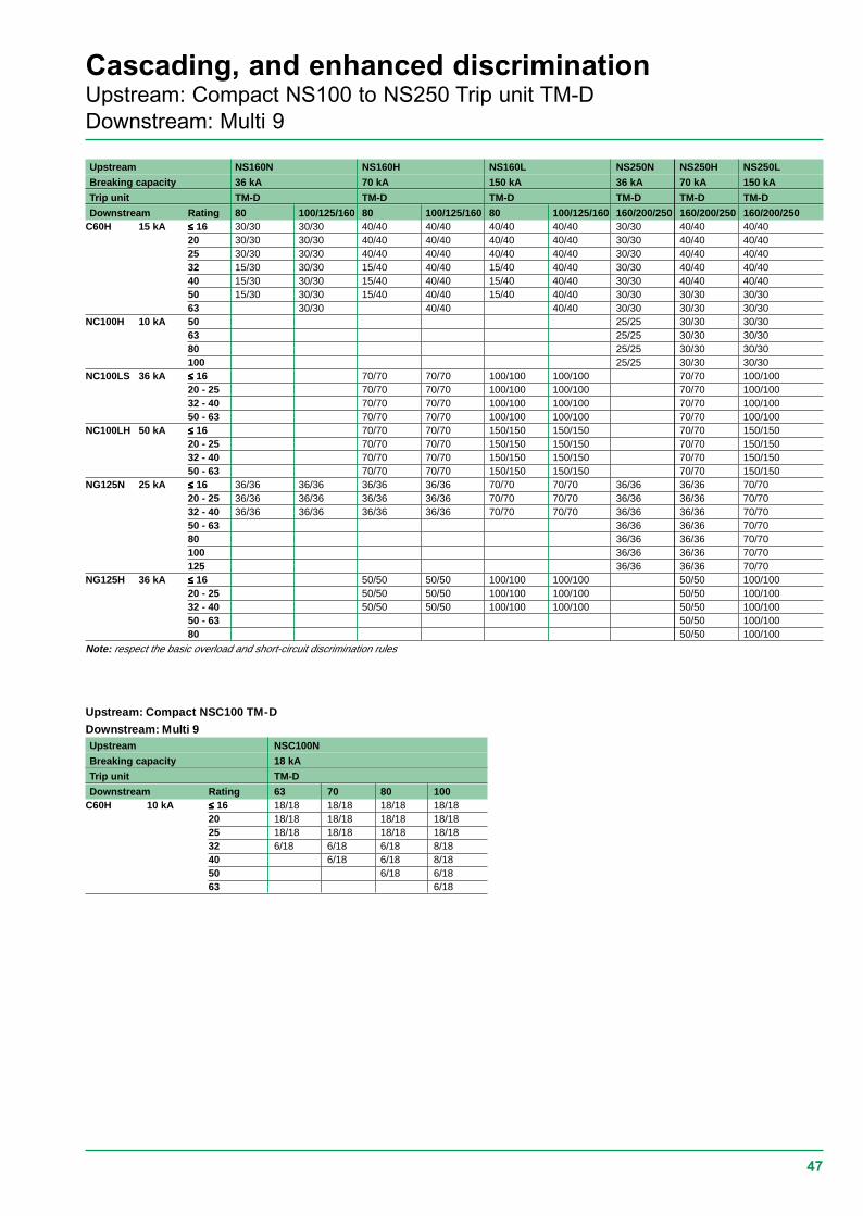
47
Cascading, and enhanced discriminationUpstream: Compact NS100 to NS250 Trip unit TM-DDownstream: Multi 9
Upstream NS160N NS160H NS160L NS250N NS250H NS250L
Breaking capacity 36 kA 70 kA 150 kA 36 kA 70 kA 150 kA
Trip unit TM-D TM-D TM-D TM-D TM-D TM-D
Downstream Rating 80 100/125/160 80 100/125/160 80 100/125/160 160/200/250 160/200/250 160/200/250C60H 15 kA ≤≤≤≤≤ 16 30/30 30/30 40/40 40/40 40/40 40/40 30/30 40/40 40/40
20 30/30 30/30 40/40 40/40 40/40 40/40 30/30 40/40 40/4025 30/30 30/30 40/40 40/40 40/40 40/40 30/30 40/40 40/4032 15/30 30/30 15/40 40/40 15/40 40/40 30/30 40/40 40/4040 15/30 30/30 15/40 40/40 15/40 40/40 30/30 40/40 40/4050 15/30 30/30 15/40 40/40 15/40 40/40 30/30 30/30 30/3063 30/30 40/40 40/40 30/30 30/30 30/30
NC100H 10 kA 50 25/25 30/30 30/3063 25/25 30/30 30/3080 25/25 30/30 30/30100 25/25 30/30 30/30
NC100LS 36 kA ≤≤≤≤≤ 16 70/70 70/70 100/100 100/100 70/70 100/10020 - 25 70/70 70/70 100/100 100/100 70/70 100/10032 - 40 70/70 70/70 100/100 100/100 70/70 100/10050 - 63 70/70 70/70 100/100 100/100 70/70 100/100
NC100LH 50 kA ≤≤≤≤≤ 16 70/70 70/70 150/150 150/150 70/70 150/15020 - 25 70/70 70/70 150/150 150/150 70/70 150/15032 - 40 70/70 70/70 150/150 150/150 70/70 150/15050 - 63 70/70 70/70 150/150 150/150 70/70 150/150
NG125N 25 kA ≤≤≤≤≤ 16 36/36 36/36 36/36 36/36 70/70 70/70 36/36 36/36 70/7020 - 25 36/36 36/36 36/36 36/36 70/70 70/70 36/36 36/36 70/7032 - 40 36/36 36/36 36/36 36/36 70/70 70/70 36/36 36/36 70/7050 - 63 36/36 36/36 70/7080 36/36 36/36 70/70100 36/36 36/36 70/70125 36/36 36/36 70/70
NG125H 36 kA ≤≤≤≤≤ 16 50/50 50/50 100/100 100/100 50/50 100/10020 - 25 50/50 50/50 100/100 100/100 50/50 100/10032 - 40 50/50 50/50 100/100 100/100 50/50 100/10050 - 63 50/50 100/10080 50/50 100/100
Note: respect the basic overload and short-circuit discrimination rules
Upstream: Compact NSC100 TM-D
Downstream: Multi 9Upstream NSC100N
Breaking capacity 18 kA
Trip unit TM-D
Downstream Rating 63 70 80 100C60H 10 kA ≤≤≤≤≤ 16 18/18 18/18 18/18 18/18
20 18/18 18/18 18/18 18/1825 18/18 18/18 18/18 18/1832 6/18 6/18 6/18 8/1840 6/18 6/18 8/1850 6/18 6/1863 6/18
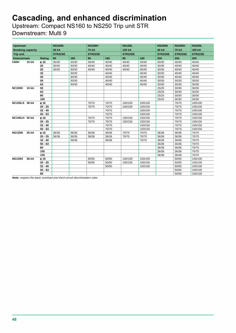
48
Cascading, and enhanced discriminationUpstream: Compact NS160 to NS250 Trip unit STRDownstream: Multi 9
Upstream NS160N NS160H NS160L NS250N NS250H NS250L
Breaking capacity 36 kA 70 kA 150 kA 36 kA 70 kA 150 kA
Trip unit STR22SE STR22SE STR22SE STR22SE STR22SE STR22SE
Downstream Rating 80 160 80 160 80 160 250 250 250C60H 15 kA ≤≤≤≤≤ 16 30/30 30/30 40/40 40/40 40/40 40/40 30/30 40/40 40/40
20 30/30 30/30 40/40 40/40 40/40 40/40 30/30 40/40 40/4025 30/30 30/30 40/40 40/40 40/40 40/40 30/30 40/40 40/4032 30/30 40/40 40/40 30/30 40/40 40/4040 30/30 40/40 40/40 30/30 40/40 40/4050 30/30 40/40 40/40 30/30 30/30 30/3063 30/30 40/40 40/40 30/30 30/30 30/30
NC100H 10 kA 50 25/25 30/30 30/3063 25/25 30/30 30/3080 25/25 30/30 30/30100 25/25 30/30 30/30
NC100LS 36 kA ≤≤≤≤≤ 16 70/70 70/70 100/100 100/100 70/70 100/10020 - 25 70/70 70/70 100/100 100/100 70/70 100/10032 - 40 70/70 100/100 70/70 100/10050 - 63 70/70 100/100 70/70 100/100
NC100LH 50 kA ≤≤≤≤≤ 16 70/70 70/70 150/150 150/150 70/70 150/15020 - 25 70/70 70/70 150/150 150/150 70/70 150/15032 - 40 70/70 150/150 70/70 150/15050 - 63 70/70 150/150 70/70 150/150
NG125N 25 kA ≤≤≤≤≤ 16 36/36 36/36 36/36 36/36 70/70 70/70 36/36 36/36 70/7020 - 25 36/36 36/36 36/36 36/36 70/70 70/70 36/36 36/36 70/7032 - 40 36/36 36/36 70/70 36/36 36/36 70/7050 - 63 36/36 36/36 70/7080 36/36 36/36 70/70100 36/36 36/36 70/70125 36/36 36/36 70/70
NG125H 36 kA ≤≤≤≤≤ 16 50/50 50/50 100/100 100/100 50/50 100/10020 - 25 50/50 50/50 100/100 100/100 50/50 100/10032 - 40 50/50 100/100 50/50 100/10050 - 63 50/50 100/10080 50/50 100/100
Note: respect the basic overload and short-circuit discrimination rules.
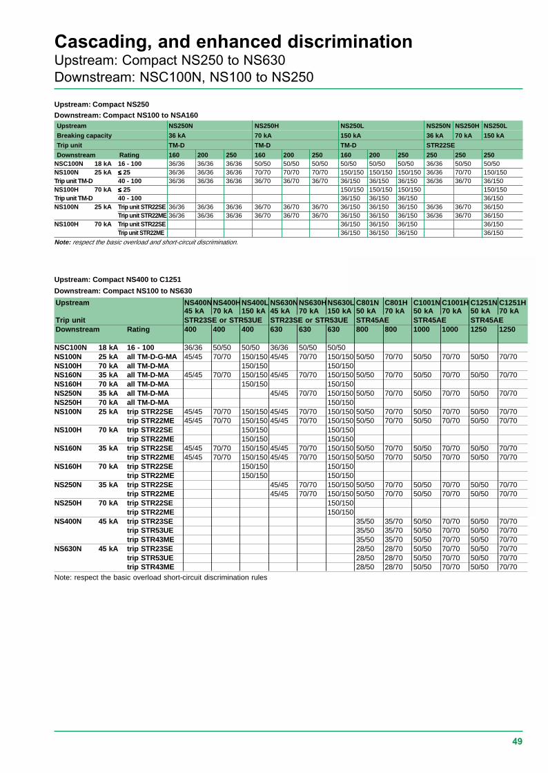
49
Cascading, and enhanced discriminationUpstream: Compact NS250 to NS630Downstream: NSC100N, NS100 to NS250
Upstream: Compact NS250Downstream: Compact NS100 to NSA160Upstream NS250N NS250H NS250L NS250N NS250H NS250L
Breaking capacity 36 kA 70 kA 150 kA 36 kA 70 kA 150 kA
Trip unit TM-D TM-D TM-D STR22SE
Downstream Rating 160 200 250 160 200 250 160 200 250 250 250 250NSC100N 18 kA 16 - 100 36/36 36/36 36/36 50/50 50/50 50/50 50/50 50/50 50/50 36/36 50/50 50/50NS100N 25 kA ≤ ≤ ≤ ≤ ≤ 25 36/36 36/36 36/36 70/70 70/70 70/70 150/150 150/150 150/150 36/36 70/70 150/150Trip unit TM-D 40 - 100 36/36 36/36 36/36 36/70 36/70 36/70 36/150 36/150 36/150 36/36 36/70 36/150NS100H 70 kA ≤≤≤≤≤ 25 150/150 150/150 150/150 150/150Trip unit TM-D 40 - 100 36/150 36/150 36/150 36/150NS100N 25 kA Trip unit STR22SE 36/36 36/36 36/36 36/70 36/70 36/70 36/150 36/150 36/150 36/36 36/70 36/150
Trip unit STR22ME 36/36 36/36 36/36 36/70 36/70 36/70 36/150 36/150 36/150 36/36 36/70 36/150NS100H 70 kA Trip unit STR22SE 36/150 36/150 36/150 36/150
Trip unit STR22ME 36/150 36/150 36/150 36/150
Note: respect the basic overload and short-circuit discrimination.
Upstream NS400NNS400HNS400L NS630NNS630HNS630L C801N C801H C1001N C1001H C1251N C1251H45 kA 70 kA 150 kA 45 kA 70 kA 150 kA 50 kA 70 kA 50 kA 70 kA 50 kA 70 kA
Trip unit STR23SE or STR53UE STR23SE or STR53UE STR45AE STR45AE STR45AEDownstream Rating 400 400 400 630 630 630 800 800 1000 1000 1250 1250
NSC100N 18 kA 16 - 100 36/36 50/50 50/50 36/36 50/50 50/50NS100N 25 kA all TM-D-G-MA 45/45 70/70 150/150 45/45 70/70 150/150 50/50 70/70 50/50 70/70 50/50 70/70NS100H 70 kA all TM-D-MA 150/150 150/150NS160N 35 kA all TM-D-MA 45/45 70/70 150/150 45/45 70/70 150/150 50/50 70/70 50/50 70/70 50/50 70/70NS160H 70 kA all TM-D-MA 150/150 150/150NS250N 35 kA all TM-D-MA 45/45 70/70 150/150 50/50 70/70 50/50 70/70 50/50 70/70NS250H 70 kA all TM-D-MA 150/150NS100N 25 kA trip STR22SE 45/45 70/70 150/150 45/45 70/70 150/150 50/50 70/70 50/50 70/70 50/50 70/70
trip STR22ME 45/45 70/70 150/150 45/45 70/70 150/150 50/50 70/70 50/50 70/70 50/50 70/70NS100H 70 kA trip STR22SE 150/150 150/150
trip STR22ME 150/150 150/150NS160N 35 kA trip STR22SE 45/45 70/70 150/150 45/45 70/70 150/150 50/50 70/70 50/50 70/70 50/50 70/70
trip STR22ME 45/45 70/70 150/150 45/45 70/70 150/150 50/50 70/70 50/50 70/70 50/50 70/70NS160H 70 kA trip STR22SE 150/150 150/150
trip STR22ME 150/150 150/150NS250N 35 kA trip STR22SE 45/45 70/70 150/150 50/50 70/70 50/50 70/70 50/50 70/70
trip STR22ME 45/45 70/70 150/150 50/50 70/70 50/50 70/70 50/50 70/70NS250H 70 kA trip STR22SE 150/150
trip STR22ME 150/150NS400N 45 kA trip STR23SE 35/50 35/70 50/50 70/70 50/50 70/70
trip STR53UE 35/50 35/70 50/50 70/70 50/50 70/70trip STR43ME 35/50 35/70 50/50 70/70 50/50 70/70
NS630N 45 kA trip STR23SE 28/50 28/70 50/50 70/70 50/50 70/70trip STR53UE 28/50 28/70 50/50 70/70 50/50 70/70trip STR43ME 28/50 28/70 50/50 70/70 50/50 70/70
Upstream: Compact NS400 to C1251
Downstream: Compact NS100 to NS630
Note: respect the basic overload short-circuit discrimination rules
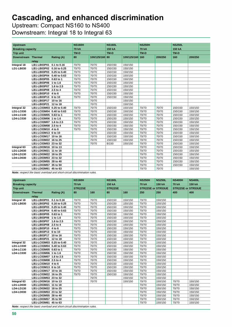
50
Cascading, and enhanced discriminationUpstream: Compact NS160 to NS400Downstream: Integral 18 to Integral 63
Upstream NS160H NS160L NS250H NS250L
Breaking capacity 70 kA 150 kA 70 kA 150 kATrip unit TM-D TM-D TM-D TM-D
Downstream Thermal Rating (A) 80 100/125/160 80 100/125/160 160 200/250 160 200/250
relayIntegral 18 LB1-LB03P01 0.1 to 0.16 70/70 70/70 150/150 150/150LD1-LB030 LB1-LB03P02 0.16 to 0.25 70/70 70/70 150/150 150/150
LB1-LB03P03 0.25 to 0.40 70/70 70/70 150/150 150/150LB1-LB03P04 0.40 to 0.63 70/70 70/70 150/150 150/150LB1-LB03P05 0.63 to 1 70/70 70/70 150/150 150/150LB1-LB03P06 1 to 1.6 70/70 70/70 150/150 150/150LB1-LB03P07 1.6 to 2.5 70/70 70/70 150/150 150/150LB1-LB03P08 2.5 to 4 70/70 70/70 150/150 150/150LB1-LB03P10 4 to 6 70/70 70/70 150/150 150/150LB1-LB03P13 6 to 10 70/70 70/70 150/150 150/150LB1-LB03P17 10 to 16 70/70 150/150LB1-LB03P21 12 to 18 70/70 150/150
Integral 32 LB1-LC03M03 0.25 to 0.40 70/70 70/70 150/150 150/150 70/70 70/70 150/150 150/150LD1-LC030 LB1-LC03M04 0.40 to 0.63 70/70 70/70 150/150 150/150 70/70 70/70 150/150 150/150LD4-LC130 LB1-LC03M05 0.63 to 1 70/70 70/70 150/150 150/150 70/70 70/70 150/150 150/150LD4-LC030 LB1-LC03M06 1 to 1.6 70/70 70/70 150/150 150/150 70/70 70/70 150/150 150/150
LB1-LC03M07 1.6 to 2.5 70/70 70/70 150/150 150/150 70/70 70/70 150/150 150/150LB1-LC03M08 2.5 to 4 70/70 70/70 150/150 150/150 70/70 70/70 150/150 150/150LB1-LC03M10 4 to 6 70/70 70/70 150/150 150/150 70/70 70/70 150/150 150/150LB1-LC03M13 6 to 10 70/70 150/150 150/150 70/70 70/70 150/150 150/150LB1-LC03M17 10 to 16 70/70 150/150 150/150 70/70 70/70 150/150 150/150LB1-LC03M22 16 to 25 70/70 150/150 150/150 70/70 70/70 150/150 150/150LB1-LC03M53 23 to 32 70/70 8/150 150/150 70/70 70/70 150/150 150/150
Integral 63 LB1-LD03M16 10 to 13 70/70 70/70 150/150 150/150LD1-LD030 LB1-LD03M21 11 to 18 70/70 70/70 150/150 150/150LD4-LD130 LB1-LD03M22 18 to 25 70/70 70/70 150/150 150/150LD4-LD030 LB1-LD03M53 23 to 32 70/70 70/70 150/150 150/150
LB1-LD03M55 28 to 40 70/70 70/70 150/150 150/150LB1-LD03M57 35 to 50 70/70 70/70 150/150 150/150LB1-LD03M61 45 to 63 70/70 70/70 150/150
Note: respect the basic overload and short-circuit discrimination rules.
Upstream NS160H NS160L NS250H NS250L NS400H NS400L
Breaking capacity 70 kA 150 kA 70 kA 150 kA 70 kA 150 kATrip unit STR22SE STR22SE STR22SE or STR53UE STR22SE or STR53UE
Downstream Thermal Rating (A) 80 160 80 160 250 250 400 400relay
Integral 18 LB1-LB03P01 0.1 to 0.16 70/70 70/70 150/150 150/150 70/70 150/150LD1-LB030 LB1-LB03P02 0.16 to 0.25 70/70 70/70 150/150 150/150 70/70 150/150
LB1-LB03P03 0.25 to 0.40 70/70 70/70 150/150 150/150 70/70 150/150LB1-LB03P04 0.40 to 0.63 70/70 70/70 150/150 150/150 70/70 150/150LB1-LB03P05 0.63 to 1 70/70 70/70 150/150 150/150 70/70 150/150LB1-LB03P06 1 to 1.6 70/70 70/70 150/150 150/150 70/70 150/150LB1-LB03P07 1.6 to 2.5 70/70 70/70 150/150 150/150 70/70 150/150LB1-LB03P08 2.5 to 4 70/70 70/70 150/150 150/150 70/70 150/150LB1-LB03P10 4 to 6 70/70 70/70 150/150 150/150 70/70 150/150LB1-LB03P13 6 to 10 70/70 70/70 150/150 150/150 70/70 150/150LB1-LB03P17 10 to 16 70/70 70/70 150/150 150/150 70/70 150/150LB1-LB03P21 12 to 18 70/70 70/70 150/150 150/150 70/70 150/150
Integral 32 LB1-LC03M03 0.25 to 0.40 70/70 70/70 150/150 150/150 70/70 150/150LD1-LC030 LB1-LC03M04 0.40 to 0.63 70/70 70/70 150/150 150/150 70/70 150/150LD4-LC130 LB1-LC03M05 0.63 to 1 70/70 70/70 150/150 150/150 70/70 150/150LD4-LC030 LB1-LC03M06 1 to 1.6 70/70 70/70 150/150 150/150 70/70 150/150
LB1-LC03M07 1.6 to 2.5 70/70 70/70 150/150 150/150 70/70 150/150LB1-LC03M08 2.5 to 4 70/70 70/70 150/150 150/150 70/70 150/150LB1-LC03M10 4 to 6 70/70 70/70 150/150 150/150 70/70 150/150LB1-LC03M13 6 to 10 70/70 70/70 150/150 150/150 70/70 150/150LB1-LC03M17 10 to 16 70/70 70/70 150/150 150/150 70/70 150/150LB1-LC03M22 16 to 25 70/70 70/70 150/150 150/150 70/70 150/150LB1-LC03M53 23 to 32 70/70 150/150 70/70 150/150
Integral 63 LB1-LD03M16 10 to 13 70/70 150/150 70/70 150/150 70/70 150/150LD1-LD030 LB1-LD03M21 11 to 18 70/70 150/150 70/70 150/150LD4-LD130 LB1-LD03M22 18 to 25 70/70 150/150 70/70 150/150LD4-LD030 LB1-LD03M53 23 to 32 70/70 150/150 70/70 150/150
LB1-LD03M55 28 to 40 70/70 150/150 70/70 150/150LB1-LD03M57 35 to 50 70/70 150/150 70/70 150/150LB1-LD03M61 45 to 63 70/70 150/150 70/70 150/150
Note: respect the basic overload and short-circuit discrimination rules.
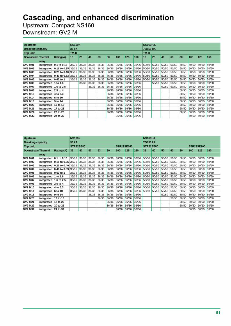
51
Cascading, and enhanced discriminationUpstream: Compact NS160Downstream: GV2 M
Upstream NS160N NS160H/L
Breaking capacity 36 kA 70/150 kA
Trip unit TM-D TM-D
Downstream Thermal Rating (A) 16 25 40 63 80 100 125 160 16 25 40 63 80 100 125 160
relayGV2 M01 integrated 0.1 to 0.16 36/36 36/36 36/36 36/36 36/36 36/36 36/36 36/36 50/50 50/50 50/50 50/50 50/50 50/50 50/50 50/50GV2 M02 integrated 0.16 to 0.25 36/36 36/36 36/36 36/36 36/36 36/36 36/36 36/36 50/50 50/50 50/50 50/50 50/50 50/50 50/50 50/50GV2 M03 integrated 0.25 to 0.40 36/36 36/36 36/36 36/36 36/36 36/36 36/36 36/36 50/50 50/50 50/50 50/50 50/50 50/50 50/50 50/50GV2 M04 integrated 0.40 to 0.63 36/36 36/36 36/36 36/36 36/36 36/36 36/36 36/36 50/50 50/50 50/50 50/50 50/50 50/50 50/50 50/50GV2 M05 integrated 0.63 to 1 36/36 36/36 36/36 36/36 36/36 36/36 36/36 36/36 50/50 50/50 50/50 50/50 50/50 50/50 50/50 50/50GV2 M06 integrated 1 to 1.6 36/36 36/36 36/36 36/36 36/36 36/36 36/36 50/50 50/50 50/50 50/50 50/50 50/50 50/50GV2 M07 integrated 1.6 to 2.5 36/36 36/36 36/36 36/36 36/36 36/36 50/50 50/50 50/50 50/50 50/50 50/50GV2 M08 integrated 2.5 to 4 36/36 36/36 36/36 36/36 50/50 50/50 50/50 50/50GV2 M10 integrated 4 to 6.3 36/36 36/36 36/36 36/36 50/50 50/50 50/50 50/50GV2 M14 integrated 6 to 10 36/36 36/36 36/36 36/36 50/50 50/50 50/50 50/50GV2 M16 integrated 9 to 14 36/36 36/36 36/36 36/36 50/50 50/50 50/50 50/50GV2 M20 integrated 13 to 18 36/36 36/36 36/36 36/36 50/50 50/50 50/50 50/50GV2 M21 integrated 17 to 23 36/36 36/36 36/36 36/36 50/50 50/50 50/50 50/50GV2 M22 integrated 20 to 25 36/36 36/36 36/36 36/36 50/50 50/50 50/50 50/50GV2 M32 integrated 24 to 32 36/36 36/36 36/36 50/50 50/50 50/50
Upstream NS160N NS160H/L
Breaking capacity 36 kA 70/150 kA
Trip unit STR22SE80 STR22SE160 STR22SE80 STR22SE160
Downstream Thermal Rating (A) 32 40 50 63 80 100 125 160 32 40 50 63 80 100 125 160
relayGV2 M01 integrated 0.1 to 0.16 36/36 36/36 36/36 36/36 36/36 36/36 36/36 36/36 50/50 50/50 50/50 50/50 50/50 50/50 50/50 50/50GV2 M02 integrated 0.16 to 0.25 36/36 36/36 36/36 36/36 36/36 36/36 36/36 36/36 50/50 50/50 50/50 50/50 50/50 50/50 50/50 50/50GV2 M03 integrated 0.25 to 0.40 36/36 36/36 36/36 36/36 36/36 36/36 36/36 36/36 50/50 50/50 50/50 50/50 50/50 50/50 50/50 50/50GV2 M04 integrated 0.40 to 0.63 36/36 36/36 36/36 36/36 36/36 36/36 36/36 36/36 50/50 50/50 50/50 50/50 50/50 50/50 50/50 50/50GV2 M05 integrated 0.63 to 1 36/36 36/36 36/36 36/36 36/36 36/36 36/36 36/36 50/50 50/50 50/50 50/50 50/50 50/50 50/50 50/50GV2 M06 integrated 1 to 1.6 36/36 36/36 36/36 36/36 36/36 36/36 36/36 36/36 50/50 50/50 50/50 50/50 50/50 50/50 50/50 50/50GV2 M07 integrated 1.6 to 2.5 36/36 36/36 36/36 36/36 36/36 36/36 36/36 36/36 50/50 50/50 50/50 50/50 50/50 50/50 50/50 50/50GV2 M08 integrated 2.5 to 4 36/36 36/36 36/36 36/36 36/36 36/36 36/36 36/36 50/50 50/50 50/50 50/50 50/50 50/50 50/50 50/50GV2 M10 integrated 4 to 6.3 36/36 36/36 36/36 36/36 36/36 36/36 36/36 36/36 50/50 50/50 50/50 50/50 50/50 50/50 50/50 50/50GV2 M14 integrated 6 to 10 36/36 36/36 36/36 36/36 36/36 36/36 36/36 36/36 50/50 50/50 50/50 50/50 50/50 50/50 50/50 50/50GV2 M16 integrated 9 to 14 36/36 36/36 36/36 36/36 36/36 36/36 50/50 50/50 50/50 50/50 50/50 50/50GV2 M20 integrated 13 to 18 36/36 36/36 36/36 36/36 36/36 50/50 50/50 50/50 50/50 50/50GV2 M21 integrated 17 to 23 36/36 36/36 36/36 36/36 50/50 50/50 50/50 50/50GV2 M22 integrated 20 to 25 36/36 36/36 36/36 36/36 50/50 50/50 50/50 50/50GV2 M32 integrated 24 to 32 36/36 36/36 36/36 50/50 50/50 50/50
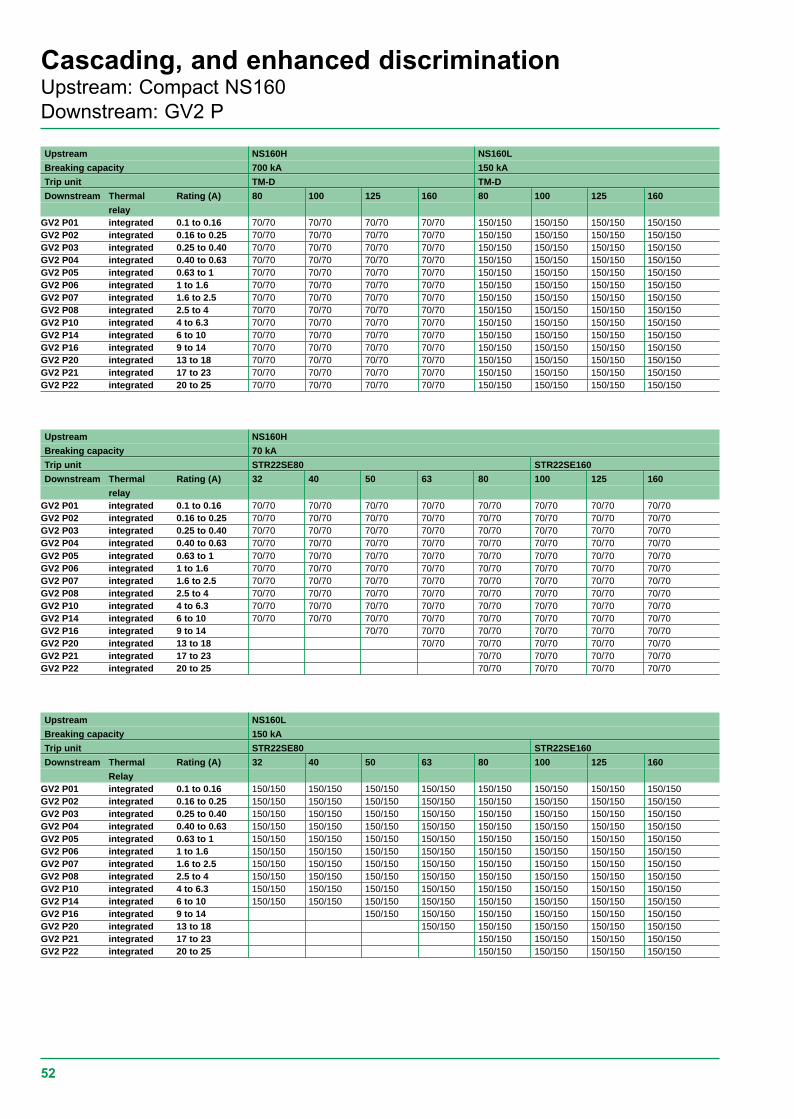
52
Cascading, and enhanced discriminationUpstream: Compact NS160Downstream: GV2 P
Upstream NS160H NS160L
Breaking capacity 700 kA 150 kA
Trip unit TM-D TM-D
Downstream Thermal Rating (A) 80 100 125 160 80 100 125 160
relayGV2 P01 integrated 0.1 to 0.16 70/70 70/70 70/70 70/70 150/150 150/150 150/150 150/150GV2 P02 integrated 0.16 to 0.25 70/70 70/70 70/70 70/70 150/150 150/150 150/150 150/150GV2 P03 integrated 0.25 to 0.40 70/70 70/70 70/70 70/70 150/150 150/150 150/150 150/150GV2 P04 integrated 0.40 to 0.63 70/70 70/70 70/70 70/70 150/150 150/150 150/150 150/150GV2 P05 integrated 0.63 to 1 70/70 70/70 70/70 70/70 150/150 150/150 150/150 150/150GV2 P06 integrated 1 to 1.6 70/70 70/70 70/70 70/70 150/150 150/150 150/150 150/150GV2 P07 integrated 1.6 to 2.5 70/70 70/70 70/70 70/70 150/150 150/150 150/150 150/150GV2 P08 integrated 2.5 to 4 70/70 70/70 70/70 70/70 150/150 150/150 150/150 150/150GV2 P10 integrated 4 to 6.3 70/70 70/70 70/70 70/70 150/150 150/150 150/150 150/150GV2 P14 integrated 6 to 10 70/70 70/70 70/70 70/70 150/150 150/150 150/150 150/150GV2 P16 integrated 9 to 14 70/70 70/70 70/70 70/70 150/150 150/150 150/150 150/150GV2 P20 integrated 13 to 18 70/70 70/70 70/70 70/70 150/150 150/150 150/150 150/150GV2 P21 integrated 17 to 23 70/70 70/70 70/70 70/70 150/150 150/150 150/150 150/150GV2 P22 integrated 20 to 25 70/70 70/70 70/70 70/70 150/150 150/150 150/150 150/150
Upstream NS160H
Breaking capacity 70 kA
Trip unit STR22SE80 STR22SE160
Downstream Thermal Rating (A) 32 40 50 63 80 100 125 160
relayGV2 P01 integrated 0.1 to 0.16 70/70 70/70 70/70 70/70 70/70 70/70 70/70 70/70GV2 P02 integrated 0.16 to 0.25 70/70 70/70 70/70 70/70 70/70 70/70 70/70 70/70GV2 P03 integrated 0.25 to 0.40 70/70 70/70 70/70 70/70 70/70 70/70 70/70 70/70GV2 P04 integrated 0.40 to 0.63 70/70 70/70 70/70 70/70 70/70 70/70 70/70 70/70GV2 P05 integrated 0.63 to 1 70/70 70/70 70/70 70/70 70/70 70/70 70/70 70/70GV2 P06 integrated 1 to 1.6 70/70 70/70 70/70 70/70 70/70 70/70 70/70 70/70GV2 P07 integrated 1.6 to 2.5 70/70 70/70 70/70 70/70 70/70 70/70 70/70 70/70GV2 P08 integrated 2.5 to 4 70/70 70/70 70/70 70/70 70/70 70/70 70/70 70/70GV2 P10 integrated 4 to 6.3 70/70 70/70 70/70 70/70 70/70 70/70 70/70 70/70GV2 P14 integrated 6 to 10 70/70 70/70 70/70 70/70 70/70 70/70 70/70 70/70GV2 P16 integrated 9 to 14 70/70 70/70 70/70 70/70 70/70 70/70GV2 P20 integrated 13 to 18 70/70 70/70 70/70 70/70 70/70GV2 P21 integrated 17 to 23 70/70 70/70 70/70 70/70GV2 P22 integrated 20 to 25 70/70 70/70 70/70 70/70
Upstream NS160L
Breaking capacity 150 kA
Trip unit STR22SE80 STR22SE160
Downstream Thermal Rating (A) 32 40 50 63 80 100 125 160
RelayGV2 P01 integrated 0.1 to 0.16 150/150 150/150 150/150 150/150 150/150 150/150 150/150 150/150GV2 P02 integrated 0.16 to 0.25 150/150 150/150 150/150 150/150 150/150 150/150 150/150 150/150GV2 P03 integrated 0.25 to 0.40 150/150 150/150 150/150 150/150 150/150 150/150 150/150 150/150GV2 P04 integrated 0.40 to 0.63 150/150 150/150 150/150 150/150 150/150 150/150 150/150 150/150GV2 P05 integrated 0.63 to 1 150/150 150/150 150/150 150/150 150/150 150/150 150/150 150/150GV2 P06 integrated 1 to 1.6 150/150 150/150 150/150 150/150 150/150 150/150 150/150 150/150GV2 P07 integrated 1.6 to 2.5 150/150 150/150 150/150 150/150 150/150 150/150 150/150 150/150GV2 P08 integrated 2.5 to 4 150/150 150/150 150/150 150/150 150/150 150/150 150/150 150/150GV2 P10 integrated 4 to 6.3 150/150 150/150 150/150 150/150 150/150 150/150 150/150 150/150GV2 P14 integrated 6 to 10 150/150 150/150 150/150 150/150 150/150 150/150 150/150 150/150GV2 P16 integrated 9 to 14 150/150 150/150 150/150 150/150 150/150 150/150GV2 P20 integrated 13 to 18 150/150 150/150 150/150 150/150 150/150GV2 P21 integrated 17 to 23 150/150 150/150 150/150 150/150GV2 P22 integrated 20 to 25 150/150 150/150 150/150 150/150
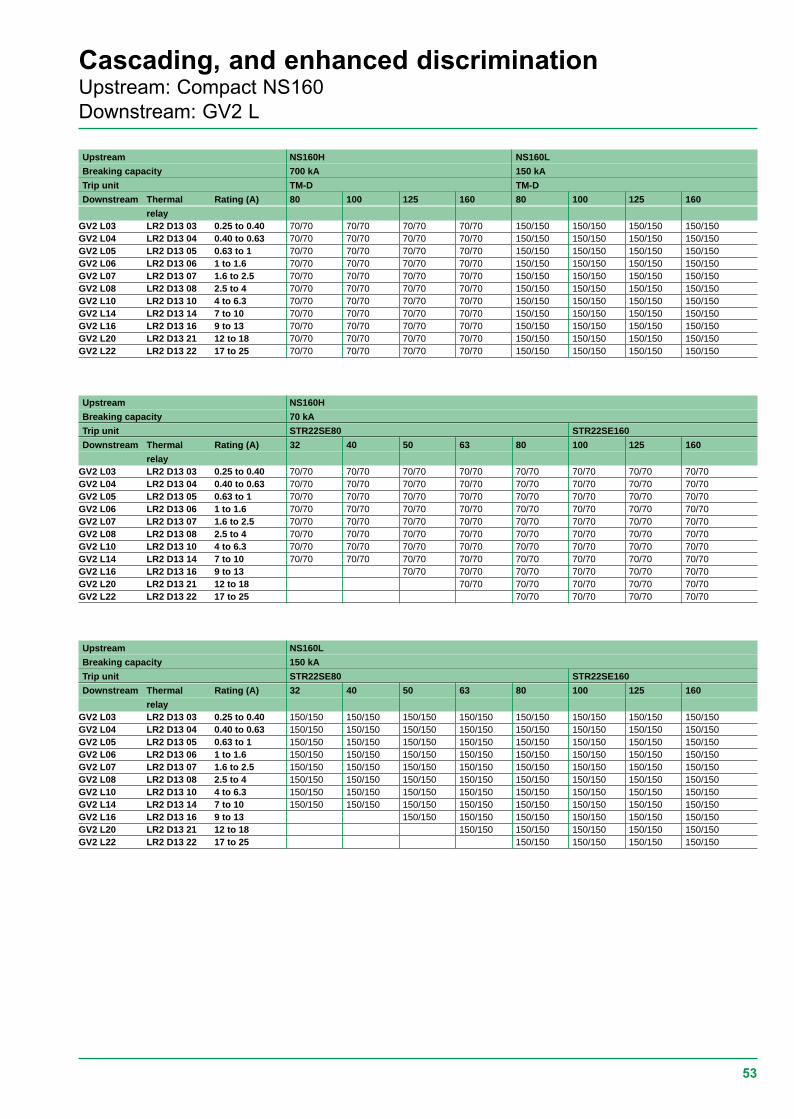
53
Cascading, and enhanced discriminationUpstream: Compact NS160Downstream: GV2 L
Upstream NS160H NS160L
Breaking capacity 700 kA 150 kA
Trip unit TM-D TM-D
Downstream Thermal Rating (A) 80 100 125 160 80 100 125 160
relayGV2 L03 LR2 D13 03 0.25 to 0.40 70/70 70/70 70/70 70/70 150/150 150/150 150/150 150/150GV2 L04 LR2 D13 04 0.40 to 0.63 70/70 70/70 70/70 70/70 150/150 150/150 150/150 150/150GV2 L05 LR2 D13 05 0.63 to 1 70/70 70/70 70/70 70/70 150/150 150/150 150/150 150/150GV2 L06 LR2 D13 06 1 to 1.6 70/70 70/70 70/70 70/70 150/150 150/150 150/150 150/150GV2 L07 LR2 D13 07 1.6 to 2.5 70/70 70/70 70/70 70/70 150/150 150/150 150/150 150/150GV2 L08 LR2 D13 08 2.5 to 4 70/70 70/70 70/70 70/70 150/150 150/150 150/150 150/150GV2 L10 LR2 D13 10 4 to 6.3 70/70 70/70 70/70 70/70 150/150 150/150 150/150 150/150GV2 L14 LR2 D13 14 7 to 10 70/70 70/70 70/70 70/70 150/150 150/150 150/150 150/150GV2 L16 LR2 D13 16 9 to 13 70/70 70/70 70/70 70/70 150/150 150/150 150/150 150/150GV2 L20 LR2 D13 21 12 to 18 70/70 70/70 70/70 70/70 150/150 150/150 150/150 150/150GV2 L22 LR2 D13 22 17 to 25 70/70 70/70 70/70 70/70 150/150 150/150 150/150 150/150
Upstream NS160H
Breaking capacity 70 kA
Trip unit STR22SE80 STR22SE160
Downstream Thermal Rating (A) 32 40 50 63 80 100 125 160
relayGV2 L03 LR2 D13 03 0.25 to 0.40 70/70 70/70 70/70 70/70 70/70 70/70 70/70 70/70GV2 L04 LR2 D13 04 0.40 to 0.63 70/70 70/70 70/70 70/70 70/70 70/70 70/70 70/70GV2 L05 LR2 D13 05 0.63 to 1 70/70 70/70 70/70 70/70 70/70 70/70 70/70 70/70GV2 L06 LR2 D13 06 1 to 1.6 70/70 70/70 70/70 70/70 70/70 70/70 70/70 70/70GV2 L07 LR2 D13 07 1.6 to 2.5 70/70 70/70 70/70 70/70 70/70 70/70 70/70 70/70GV2 L08 LR2 D13 08 2.5 to 4 70/70 70/70 70/70 70/70 70/70 70/70 70/70 70/70GV2 L10 LR2 D13 10 4 to 6.3 70/70 70/70 70/70 70/70 70/70 70/70 70/70 70/70GV2 L14 LR2 D13 14 7 to 10 70/70 70/70 70/70 70/70 70/70 70/70 70/70 70/70GV2 L16 LR2 D13 16 9 to 13 70/70 70/70 70/70 70/70 70/70 70/70GV2 L20 LR2 D13 21 12 to 18 70/70 70/70 70/70 70/70 70/70GV2 L22 LR2 D13 22 17 to 25 70/70 70/70 70/70 70/70
Upstream NS160L
Breaking capacity 150 kA
Trip unit STR22SE80 STR22SE160
Downstream Thermal Rating (A) 32 40 50 63 80 100 125 160
relayGV2 L03 LR2 D13 03 0.25 to 0.40 150/150 150/150 150/150 150/150 150/150 150/150 150/150 150/150GV2 L04 LR2 D13 04 0.40 to 0.63 150/150 150/150 150/150 150/150 150/150 150/150 150/150 150/150GV2 L05 LR2 D13 05 0.63 to 1 150/150 150/150 150/150 150/150 150/150 150/150 150/150 150/150GV2 L06 LR2 D13 06 1 to 1.6 150/150 150/150 150/150 150/150 150/150 150/150 150/150 150/150GV2 L07 LR2 D13 07 1.6 to 2.5 150/150 150/150 150/150 150/150 150/150 150/150 150/150 150/150GV2 L08 LR2 D13 08 2.5 to 4 150/150 150/150 150/150 150/150 150/150 150/150 150/150 150/150GV2 L10 LR2 D13 10 4 to 6.3 150/150 150/150 150/150 150/150 150/150 150/150 150/150 150/150GV2 L14 LR2 D13 14 7 to 10 150/150 150/150 150/150 150/150 150/150 150/150 150/150 150/150GV2 L16 LR2 D13 16 9 to 13 150/150 150/150 150/150 150/150 150/150 150/150GV2 L20 LR2 D13 21 12 to 18 150/150 150/150 150/150 150/150 150/150GV2 L22 LR2 D13 22 17 to 25 150/150 150/150 150/150 150/150
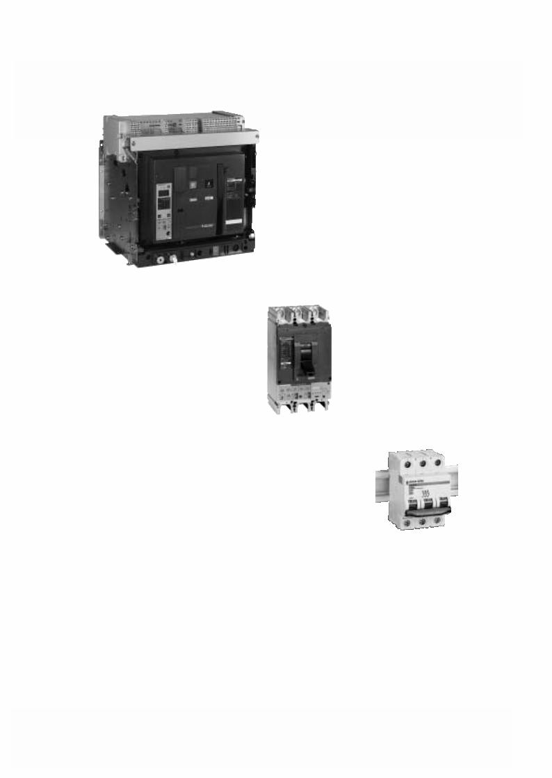
54