Embed Size (px)
Citation preview

Mercedes-Benz Vehicle Communication
Software Manual
August 2013
EAZ0025B41D Rev. A

Trademarks AcknowledgementsSnap-on is a trademark of Snap-on Incorporated.
All other marks are trademarks of their respective holders.
Copyright Information©2013 Snap-on Incorporated
All rights reserved.
DisclaimerThe information, specifications and illustrations in this manual are based on the latest information available at the time of printing.
Snap-on reserves the right to make changes at any time without notice.
Visit our Web site at:http://diagnostics.snapon.com
For Technical Assistance Call:1-800-424-7226
ii

Safety Information
For your own safety and the safety of others, and to prevent damage to the equipment and vehicles upon which it is used, it is important that the accompanying Safety Information be read and understood by all persons operating, or coming into contact with, the equipment. We suggest you store a copy near the unit in sight of the operator
This product is intended for use by properly trained and skilled professional automotive technicians. The safety messages presented throughout this manual are reminders to the operator to exercise extreme care when using this test instrument.
There are many variations in procedures, techniques, tools, and parts for servicing vehicles, as well as in the skill of the individual doing the work. Because of the vast number of test applications and variations in the products that can be tested with this instrument, we cannot possibly anticipate or provide advice or safety messages to cover every situation. It is the automotive technician’s responsibility to be knowledgeable of the system being tested. It is essential to use proper service methods and test procedures. It is important to perform tests in an appropriate and acceptable manner that does not endanger your safety, the safety of others in the work area, the equipment being used, or the vehicle being tested.
It is assumed that the operator has a thorough understanding of vehicle systems before using this product. Understanding of these system principles and operating theories is necessary for competent, safe and accurate use of this instrument.
Before using the equipment, always refer to and follow the safety messages and applicable test procedures provided by the manufacturer of the vehicle or equipment being tested. Use the equipment only as described in this manual.
Read, understand and follow all safety messages and instructions in this manual, the accompanying safety manual, and on the test equipment.
Safety Message ConventionsSafety messages are provided to help prevent personal injury and equipment damage. All safety messages are introduced by a signal word indicating the hazard level.
! DANGERIndicates an imminently hazardous situation which, if not avoided, will result in death or serious injury to the operator or to bystanders.
! WARNINGIndicates a potentially hazardous situation which, if not avoided, could result in death or serious injury to the operator or to bystanders.
! CAUTIONIndicates a potentially hazardous situation which, if not avoided, may result in moderate or minor injury to the operator or to bystanders.
iii

Safety Information Important Safety Instructions
Safety messages contain three different type styles.
• Normal type states the hazard.• Bold type states how to avoid the hazard.• Italic type states the possible consequences of not avoiding the hazard.
An icon, when present, gives a graphical description of the potential hazard.
Example:
! WARNINGRisk of unexpected vehicle movement.• Block drive wheels before performing a test with engine running.A moving vehicle can cause injury.
Important Safety InstructionsFor a complete list of safety messages, refer to the accompanying safety manual.
SAVE THESE INSTRUCTIONS
iv

Contents
Safety Information ..................................................................................................................... iii
Contents ...................................................................................................................................... v
Chapter 1: Using This Manual ................................................................................................... 1Conventions.................................................................................................................................. 1
Bold Text ................................................................................................................................ 1Terminology ........................................................................................................................... 1
Notes and Important Messages.................................................................................................... 2Notes...................................................................................................................................... 2Important ................................................................................................................................ 2
Chapter 2: Introduction.............................................................................................................. 3
Chapter 3: Operations................................................................................................................ 4Identifying the Vehicle .................................................................................................................. 4Selecting a System....................................................................................................................... 6Connecting to a Vehicle................................................................................................................ 6Selecting a Test.......................................................................................................................... 11Main Menu Selections ................................................................................................................ 11
Codes................................................................................................................................... 11Data ..................................................................................................................................... 11Functional Tests................................................................................................................... 12Review ECU ID .................................................................................................................... 13Stop Communication............................................................................................................ 13
Scanner Demonstration Program ............................................................................................... 13
Chapter 4: Testing .................................................................................................................... 14Testing EA/CC/ISC Systems ...................................................................................................... 14
Note the following when testing EA/CC/ISC systems: ......................................................... 15Testing DAS (Immobilizer) Systems........................................................................................... 15
Central Locking .................................................................................................................... 15DAS Versions....................................................................................................................... 16
Chapter 5: Data Parameters .................................................................................................... 21Alphabetical Parameter List........................................................................................................ 22Engine Parameters..................................................................................................................... 36Transmission Parameters........................................................................................................... 86
Appendix A: Troubleshooting and Communication Problems ............................................ 98Startup Troubleshooting ............................................................................................................. 98Communication Problems .......................................................................................................... 98Common Problems..................................................................................................................... 99Common Symptoms ................................................................................................................... 99
Check Scanner Connection and Operation.......................................................................... 99
v

Contents
Appendix B: Terms, Abbreviations and Acronyms............................................................. 100Terms ....................................................................................................................................... 100Abbreviations and Acronyms.................................................................................................... 100
Index ........................................................................................................................................ 108
vi
Chapter 1 Using This Manual
This manual contains instructions for testing Mercedes-Benz vehicles. Some of the Illustrations shown in this manual may contain modules and optional equipment that are not included on your system. Contact your sales representative for availability of accessories and optional equipment.
1.1 ConventionsThis manual uses the conventions described below.
1.1.1 Bold TextBold text is used for emphasis and to highlight selectable items such as buttons and menu options.
Example:
• Select OK to continue.
1.1.2 TerminologyCertain terms are used to command specific actions throughout this manual. Those terms are described below.
SelectThe term “select” means to highlight a menu item or other option, then pressing the Y/a, OK, Accept, or similar button to activate it.
Example:
• Select Functional Tests.
ScrollThe term “scroll” means moving the cursor or changing data by using the directional arrow buttons, scroll bars, or other means.
Example:
• Scroll to see any other codes and the data list.
1

Using This Manual Notes and Important Messages
Scan ToolThe term “scan tool” is used to refer to any tool that communicates directly with the vehicle data stream. When necessary, the term “Scanner” is used to distinguish Snap-on equipment from another diagnostic device, such as the Mercedes-Benz factory scan tool.
1.2 Notes and Important MessagesThe following messages appear throughout this manual.
1.2.1 NotesA NOTE provides helpful information such as explanations, tips, and comments.
Example:
NOTE:i For additional information refer to...
1.2.2 ImportantIMPORTANT indicates a situation which, if not avoided, may result in damage to the test equipment or vehicle.
Example:
IMPORTANT:To avoid incorrect TPS adjustment or component damage, be sure to follow the on-screen instructions. Refer to a vehicle service manual for complete test or adjustment procedures.
2

Chapter 2 Introduction
The Mercedes-Benz Vehicle Communication Software provides extensive vehicle-specific engine, transmission, antilock brake system (ABS) and airbag trouble codes, and selected functional tests.
This manual is designed to guide you through control systems tests of Mercedes-Benz vehicles.
The first two sections of this manual overview safety and usage conventions. The remainder of this guide is divided into the following chapters:
• Operations, on page 4 takes you through basic Scanner operations from identifying the vehicle to selecting tests from a Main Menu screen.
• Testing, on page 14 offers testing information and procedures for transmission control systems.
• Data Parameters, on page 21 defines Mercedes-Benz data parameters and explains how they display on the screen.
• Troubleshooting and Communication Problems, on page 98 offers advice for troubleshooting Scanner-to-vehicle communication and other issues.
• Terms, Abbreviations and Acronyms, on page 100 lists abbreviations used in this manual.
3

Chapter 3 Operations
Identifying the VehicleThe Scanner typically identifies a vehicle using certain characters of the vehicle identification number (VIN). The Scanner vehicle identification (ID) process prompts to you enter VIN characters and answer questions about the vehicle to be tested.
For some vehicles, the Scanner may display two or more engine choices. Be sure to scroll to confirm the number of engine choices. The engine number is stamped on the engine block or cylinder head, however, the exact location varies and is often difficult to see on an installed engine. For example, the number is often behind the water pump on V8 engines.
For 129 and 140 models, there may be multiple engine selections that are seen by scrolling after selecting the year. Typically, multiple engine choices apply to other markets and only one engine is used on North American vehicles for any given year.
Table 3-1 provides some helpful tips for selecting the correct engine.Table 3-1 VIN selections for North American vehicles (sheet 1 of 2)
VIN Engine Selection
VIN FA67119.972 used on 1995 models only119.982 used on 1996–2000 models
VIN FA76120.981 used on 1995 models only120.983 used on 1996–98 models
VIN GA32104.990 used on 1993 models only104.994 used on 1994 models only
VIN GA43119.971 used on 1995 models only119.981 used on 1996–98 models
VIN GA51119.970 used on 1995 models only119.980 used on 1996–98 models
VIN GA57120.980 used on 1995 models only120.982 not used on 1995 U.S. models
VIN GA70119.970 used on 1995 models only119.980 used on 1996–98 models
VIN GA76120.980 used on 1995 models only120.982 not used on 1995 US models
VIN EA30 (1988–92)103.980 not used in US103.983 used in US
VIN JF72119.980 not used in US (5.0L-V8)119.985 used in US (4.2L-V8)
VIN AB54 112.942 used on 1998–2003 modelsVIN AB57 112.970 used on 2003–2005 modelsVIN AB72 113.942 used on 1999–2001 modelsVIN AB74 113.981 used on 2000–2002 modelsVIN AB75 113.964 used on 2002–2005 models
4

Operations Identifying the Vehicle
When multiple engine choices are listed, only the correct engine choice communicates with the Scanner. If the Scanner does not communicate after selecting one engine, select the other engine and try again. Always scroll to verify if any additional engine choices are available.
Multiple engine systems are sometimes listed together as one selection (for example HFM/ME2) because vehicle systems may vary depending on country. The Scanner automatically identifies the correct system.
Selecting System ID mode allows the user to go to the selected system and control unit. The scan tool displays a list of systems or modules with which the scan tool can communicate.
NOTE:i The list of systems or modules that the scan tool can communicate with is not customized to the
test vehicle.
Selecting a module that is not fitted to the vehicle will result in a “No Communication” error message. Some systems will list the same systems or modules more than once; the correct choice is the only one that will communicate with the scan tool.
VIN AJ76 155.980 used on 2005 modelsVIN FA68 113.961 used on 1999–2002 modelsVIN FA76 120.983 used on 1997–2002 modelsVIN KK47 111.973 used on 1998–2000 modelsVIN KK49 111.983 used on 2001–2004 modelsVIN KK65 112.947 used on 2001–2004 modelsVIN KK66 112.960 used on 2002–2004 modelsVIN PJ74 113.991 used on 2003 modelsVIN PJ75 113.960 used on 2000 modelsVIN PJ76 275.950 used on 2003–2005 modelsVIN RF76 113.988 used on 2005 modelsVIN SK74 113.992 used on 2003 modelsVIN SK75 113.963 used on 2003 modelsVIN SK76 275.960 used on 2004 modelsVIN SK79 275.981 used on 2005 modelsVIN TJ 75 113.987 used on 2003 modelsVIN TJ 76 113.987 used on 2004 models
VIN UF70113.967 used on 2003 models113.969 used on 2004 models
VIN UF76 113.990 used on 2004 modelsVIN UF83 113.969 used on 2004 modelsVIN WK56 272.963 used on 2005 modelsVIN WK73 113.989 used on 2005 models
Table 3-1 VIN selections for North American vehicles (sheet 2 of 2)
VIN Engine Selection
5

Operations Selecting a System
Selecting a SystemOnce you have confirmed a vehicle identification, the System List menu displays. This menu shows all the systems available for testing.
z Note the following when selecting a system for testing:• The terms “left” and “right” refer to separate engine bank control systems for 12-cylinder
engines and assume left and right from the position of a seated driver. OBD-II terminology uses Bank 1 and Bank 2. The Scanner calls Bank 1 (cylinders 1–6) on the passenger side, “(Right),” and Bank 2 (cylinders 7–12) on the driver's side, “(Left).”
• Bank 1 is controlled by ME 1 and Bank 2 is controlled by ME 2.• For the V12 engine, long intake runners with a MAF sensor for each bank are located on the
opposite side of the engine.• For those vehicles with multiple system choices, if the Scanner is not able to establish
communication using the first system choice, try again using an alternate system choice. See “Appendix A Troubleshooting and Communication Problems” on page 98 for help trying to establish communication.
Connecting to a VehicleAfter selecting from the System List, the Scanner displays a connection message that tells you which adapter and personality key to use to connect the Scanner for testing. Each test adapter plugs into a specific vehicle diagnostic connector and attaches to one end of the data cable. The other end of the cable attaches to the Scanner. Captive screws secure both data cable ends.
The following adapters are available to connect the Scanner to Mercedes-Benz vehicles:
• MB-1—for the 38-pin underhood connector.• MB-2A—for the 8-pin or 16-pin underhood connector.• DL-16—for 1996 and later vehicles with an OBD-II style connector.
When available, it is recommended to use the underhood 38-pin connector for those vehicles from approximately 1996–2001. For those vehicles with dual connectors, the under-dash 16-pin may have limited functionality.
Use the following adapter + Personality Key™ combinations for the appropriate systems.
• DL16 + S4—KLA/TAU airco system (A/SLK-series)• MB1 + S33—KLA/TAU airco system• MB1 + S34—ZAE airbag, EWM (electronic gear selector) system
NOTE:i When a CIS-E vehicle is identified, a connector message appears instructing you to use the
“MB-2 + 2.5 mm adapter cable” which is designed to be used in conjunction with the yellow lead on the MB-2 adapter. This 2.5 mm adapter is currently not available in the Scanner accessory package (many test lead kits may have a standard banana plug for the 2.5 mm adapter). On CIS-E, a duty ratio test reads current faults via a duty-cycle output. The vehicle diagnostic connector is a round 9-pin. Connect to pin 3 as directed by the display message.
6

Operations Connecting to a Vehicle
Each test adapter connects to one of the following vehicle diagnostic connectors.
Figure 3-1 MB-1 adapter Figure 3-2 MB-2A adapter
Figure 3-3 DL-16
7

Operations Connecting to a Vehicle
Figure 3-4 38-pin connector—fits MB-1 adapter
Pin Function Pin Function
1 Ground, circuit 31 (W12, W15, electronics ground) 14 On-off ratio, engine 119 LH-SFI, engine 120
LH-SFI (right)2 Voltage, circuit 87 or 15z
15On-off ratio, engine 120 LH-SFI (left)
3 Voltage, circuit 30 Instrument cluster
4
Electronic diesel system16
Air conditioning (models 124, 202, 208, 210)
Electronic distributor-type fuel injection (diesel) Tempmatic air conditioning (model 170)
Electronic inline fuel injection (diesel)
17
Distributor ignition, engines 104, 119, engine 120 (right)
HFM sequential multiport fuel injection/ignition
TD-speed signal (time division) (diesel) (model 140)
LH sequential multiport fuel injection, engines 104, 119, 120 (right)
TN-speed signal, LH-SFI engines, HFM (model 202)
ME sequential multiport fuel injection/ignition, engines 119, 120 (right) 18 Distributor ignition, engine 120 (left)
5
LH sequential multiport fuel injection, engine 120 (left) 19 Diagnostic module
ME sequential multiport fuel injection/ignition, engine 120 (left) 20
Pneumatic system equipment (model 140)
6
Antilock brake system Combination control module (model 210)Electronic traction system
21Convenience feature (model 140)
Acceleration slip regulation Roadster soft top (model 129)Electronic stability program 22 Roll bar (model 129)
7Electronic accelerator 23 Anti-theft alarmCruise control/idle speed control 24–25 Not used
8Base module 26 Automatic locking differential (model 202)Brake assist 27 Not used
9 Automatic locking differential (models 124, 129, 140) 28 Parktronic system (model 140)
10 Electronic transmission control 29 Not used11 Adaptive damping system 30 Airbag/ETR (SRS)12 Speed-sensitive power steering 31 Remote central locking
13
TNA-signal (gasoline) LH-SFI engines 32–33 Not usedTD-signal (diesel) (model 210) 34 Communication and navigation systemTN-signal (gasoline), HFM (ME)-SFI engines 35–38 Not used
8

Operations Connecting to a Vehicle
Figure 3-5 16-pin OBD-I connector—fits MB-2 adapter
US Models California Models Only (With LED)
Pin Function Pin Function1 Ground 1 Ground2 Not used 2 Push-button for on-board diagnostics3 Continuous fuel injection
3Continuous fuel injection
4 Electronic diesel system Diagnostic module5 4MATIC 4 LED6 Airbag/ETR (SRS) 5 Automatic locking differential
7Air conditioning (model 124) 6 Airbag/ETR (SRS)Roll bar (model 129)
7Air conditioning (model 124)
8
Distributor ignition Roll bar (model 129)HFM sequential multiport fuel injection/ignition
8Distributor ignition
Pressurized engine control HFM sequential multiport fuel injection/ignition
9Adaptive damping system
9Adaptive damping system
Roll bar (model 124) Roll bar (model 124)10 TN-signal (gasoline)
10Roadster soft top (model 129)
11 Anti-theft alarm TN-signal (gasoline)12 Remote central locking 11 Anti-theft alarm13 Electronic transmission control 12 Remote central locking
14
Electronic accelerator (model 124) 13 Electronic transmission controlCruise control/idle speed control (model 124)
14
Electronic accelerator (model 124)
Engine systems control module (MAS) (model 129)
Cruise control/idle speed control (model 124)
15 Not used Engine systems control module (MAS) (model 129)
16 Circuit 1515 Not used16 Circuit 15
9
Operations Connecting to a Vehicle
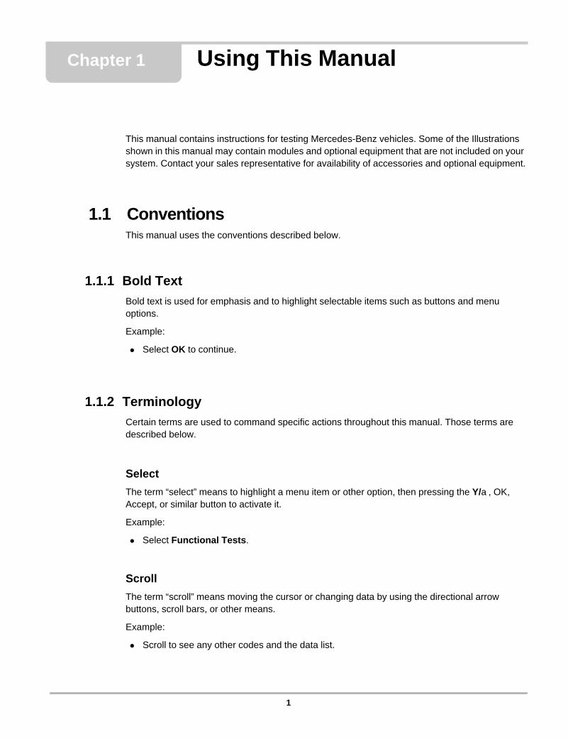
Figure 3-6 8-pin connector—fits MB-2 adapter
Figure 3-7 16-pin OBD-II connector—fits DL-16 adapter
Pin Function1 Ground2 Not used3 Continuous fuel injection
4Diesel injection systemElectronic idle speed controlElectronic diesel
5Automatic locking differentialAutomatic-engaged 4WD (model 124 only)
6 Airbag7 Air conditioning8 Not used
Pin Function Pin Function
1 Not used 9 Electronic Traction System (ETS), model 163
2 Not used 10 Not used3 TNA-signal (gasoline) 11 Electronic transmission control (ETC)4 Circuit 31, ground 12 All Activity Module (AAM)5 Circuit 31, electric ground 13 Airbag/ETR (SRS)6 CAN interior bus (H) 14 CAN interior bus (L)7 Motor electronics (ME) 15 Instrument cluster8 Circuit 87, voltage supply 16 Circuit 30, voltage supply
10

Operations Selecting a Test
z Note the following when connecting the Scanner to the vehicle:• “Left” or “Right,” when included in the connection message, assumes that you are seated in
the driver seat.• When the connection message screen refers to the MB-2 adapter, use the MB-2A adapter.• The MB-1 and DL-16 adapters require a Personality Key™. See the on-screen connection
instructions for the vehicle you are testing for the correct Personality Key™.• The Scanner displays [MORE] if a message exceeds four lines. Scroll to display the
additional lines.
Follow the on-screen instructions to connect the scan tool to the vehicle.
Selecting a TestAfter a vehicle has been identified, the Scanner has been connected to the appropriate vehicle test connector, and a system has been selected, a Main Menu specific to the identified vehicle displays, and you may begin testing.
Main Menu SelectionsThe Main Menu presents selections only for the specific vehicle being tested.
The Mercedes-Benz Main Menu contains the following general functions:
• Codes—displays one of three types of diagnostic trouble codes (see “Codes” on page 11).• Data—allows the monitoring of various sensors, switches, fuel adaptation values, and
actuator inputs and outputs on many Mercedes-Benz vehicles (see “Data” on page 11).• Functional Tests—provides specific tests for the identified vehicle (see “Functional Tests” on
page 12).• Stop Communication—disables the active communication link between the Scanner and the
vehicle control module.• Review ECU ID—displays identification characteristics of the active control module.
CodesSelect Codes from the Main Menu and the Scanner displays any existing codes from the ECU “live.” This means that as the ECU sets or clears a code, the Scanner shows or removes that code from the screen almost instantaneously.
Data Select Data from the Main Menu and the Scanner displays a menu of data groups. Each data group includes only parameters that relate to that particular function. The number of groups
11

Operations Main Menu Selections
available, The type of data available, and the order in which the groups are listed varies by model. A typical data group listing would include:
• Oil Information• Adaptation Values• Speed Regulation• Fan Status• Start Enable• Values at Idle• Air Conditioner Values• Lambda Pairs• Lambda Control Downstream• Lambda Control Upstream• Engine Running Values• Air Pump Values• Knock Values• Injection/Ignition• Spark Current 1—8• Fault Counter• Cruise Control• Running Temperature
Combining data into groups results in a much shorter data list and allows for a faster update rate.
Functional TestsSelecting FUnctional Tests from the Main Menu displays a menu that varies depending on the vehicle identified.
Each selection from the Functional Tests menu allows you to activate and test various components and systems of the engine management system.
Actuator TestsActuator tests command the ECU to activate components and systems, such as injectors, the throttle valve, adaptive strategy, or the fuel pump. The Scanner displays only those tests available to the identified vehicle and system (ECU).
For many components, you can conduct an auditory test—a relay clicks or a pump vibrates. Be aware that actuators can be mounted anywhere in the vehicle, such as under the dashboard, hood, or trunk.
If you hear no reaction where one is expected, test the actuator circuit with a digital multimeter or a digital graphing meter such as the Vantage PRO™ Meter. Use these instruments to confirm whether the ECU properly controls the component.
12

Operations Scanner Demonstration Program
Special FunctionsThis selection opens a menu of unique tests, such as relearn procedures. Follow the on-screen instructions to check status and reprogram learned values.
Review CodingThis test displays the programmed VIN number and other relevant information.
Review ECU IDThis test displays ECU identification information. Highlight and select Review ECU ID to access the information. The display may take more than one screen, scroll to read the complete test results.
Stop CommunicationThis selection severs the communication link between the Scanner and the vehicle ECU. Use it to end a test session before switching the Scanner off or disconnecting the data cable.
Scanner Demonstration ProgramThe Mercedes-Benz software contains programs that demonstrate test capabilities without connecting to a vehicle. The demonstration program can help you become familiar with Scanner menus and operation by providing mock data and test results for a sample vehicle ID. The demonstration program is accessed at the vehicle identification phase of Scanner operations.
z To access a demonstration:1. Open the Mercedes-Benz database.2. Highlight and select Training Mode.
A series of vehicle identification screens display.3. Select a vehicle identification
The System Selection menu displays and you are in demonstration mode.
13

Chapter 4 Testing
This chapter provides limited information and procedures for the following control systems:
• Engine (gas)– CIS-E– LH– HFM– ME versions 1.0, 2.0, 2.1, 2.7, 2.7.1, 2.8– SIM4 & SIM4/LSE– PEC– MSM– MME– ME– DI
• Engine (diesel)– Anti-Jerk Control, Idle Speed Control (AJC/ISC, ELR)– Electronic Diesel System (EDS)– IFI/DFI/DSV– CDI
• Transmission (EAG, EGS, EGS5.2, KGS)• Transfer Case (VG, VGS)• Electronic Shift Control Module (EWM203, EWM210, EWM220)• Airbag (ZAE, AB2, ARMIN, TAU)• Climate Control (KLA, TAU)• Diagnostic Module (DM)• Distributor Ignition (DI, EZ)• Electronic Actuator/Cruise Control/Idle Speed Control (EA/CC/ISC, ETL)• Base Module (GM)• Brake Systems (ABS, BAS, EHB)
See “Main Menu Selections” on page 11 for general Scanner testing information.
Testing EA/CC/ISC SystemsLH and HFM fuel management systems have a separate module that controls the electronic actuator, cruise control, and idle speed control (EA/CC/ISC). The ME control module on 1996 and later vehicles integrated all operations into the ME control system.
The exact Electronic Actuator (EA), Cruise Control (CC), and Idle Speed Control (ISC) module variations (i.e., EA/CC/ISC, CC/ISC, and ISC) are dependent on installed options like cruise
14

Testing Testing DAS (Immobilizer) Systems
control and traction control (ASR). Vehicles with ASR usually have an orange warning light on the instrument cluster.
Note the following when testing EA/CC/ISC systems:• The EA/CC/ISC modules are on the CAN bus and can turn the Check Engine Light on.
Always check, repair and clear any EA/CC/ISC codes. • The ECU or other modules may also report a code pointing to a fault at the EA/CC/ISC.
Testing DAS (Immobilizer) SystemsThe Drive Authorization System (DAS) is the name for the Mercedes Immobilizer system combining vehicle access and drive authorization. Prior to 1996, DAS was separated from the engine control module, and ignition switch operation was based solely on a mechanical key. An early version of DAS was first introduced in approximately 1993 when Mercedes started networking DAS, the engine, transmission, ABS, and traction control systems on a common data bus called CAN.
The Mercedes pneumatic control door lock system has been in existence since the early 1980s, and although now it is much more advanced, it is still in use today. It steadily became more sophisticated as features were added like central locking, starter lock-out, and steering lock-out.
NOTE:i Some late models, such as ML- and C-class series, have completely eliminated the pneumatic
control system and now use a fully electronic door lock system.
Central LockingCentral Locking is the ability to lock or unlock the complete vehicle at one time and from multiple locations using either an infrared beam or a radio frequency signal. The infrared remote control
Table 4-1 1992–96 Mercedes EA/CC/ISC application coverage
Series Model Year Chassis # Engine #
124
300CE 1993–95 124.052/092 104.992
300E1993 124.028 104.9421993–95 124.032 104.992
400E 1992–95 124.034 119.975500E 1992–94 124.036 119.974
140
300SE 1992–93 140.032 104.990400SE 1992 140.042
119.971400SEL 1993–95 140.043600SEC 1993–95 140.076
120.980600SEL 1992 140.057S320 1994–96 140.032 104.994
202 C280 1994–95 202.028 104.941
15
Testing Testing DAS (Immobilizer) Systems
(IFZ) was introduced in late 1992 as a standard feature. With central locking, lock actuators are no longer connected electrically, therefore the central locking, anti-theft, and convenience systems can no longer be operated with the mechanical key. Instead, a remote control module operates the complete vehicle locking system through the pneumatic control module. This keyless entry system consists of a remote control module, transmitter, pneumatic control module, and two receivers.
The infrared remote control can only be operated with a vehicle-specific transmitter as they are matched to one another. The remote control transmitter signal consists of a fixed code that must match the receiver. The code is “rolling,” which means it is changed each time it is actuated.
NOTE:i The mechanical key can still be used in emergency to open the driver's door or trunk. All door
locks are equipped with micro switches which should disable the anti-theft alarm (ATA) if the correct key is used to unlock the door. If the ATA does not disarm, insert the key into the ignition and turn the ignition switch to the ON position.
DAS VersionsIn approximately 1991, the ATA system added the K38 relay which controlled starter motor operation. In approximately 1993, this function was added to the RCL control module, introducing the immobilizer system which added additional RCL control functions: interruption of ignition, fuel, starter or vacuum. The important difference is that the RCL control module communicates on a CAN bus to other control modules.
NOTE:i If the vehicle is unlocked with the mechanical key, the ignition switch may not operate to start the
vehicle. The vehicle may need to be unlocked using the remote key to unlock the immobilizer, which then permits the engine to start.
DAS 2DAS 2 integrated the immobilizer function and engine control into one system. Activation and deactivation occurs whenever the car is locked or unlocked either with the remote transmitter or the mechanical key.
This system introduced the rolling code for the remote control on the C, E and S/SL class in 1996. Rolling code changes the access code each time the transmitter (in the remote key) and receiver (in the vehicle) communicate. Once the receiver authorizes the received code, it sends a new code back to the remote key.
The engine and DAS control modules are locked together with a common identification code that cannot be erased. Engine and DAS control modules have to be version coded if replaced.
Table 4-2 DAS 2 characteristics
Triggered By Signal Type Authorization Checked By
Operator Feedback
Authorized Start Result
Remote or door and trunk switches
Remote locking IR or door and trunk switches
RCL N-54 Mirror LEDs NO fuel injection
16

Testing Testing DAS (Immobilizer) Systems
NOTE:i On some models, the green and red LEDs on the rear view mirror flash alternately if the engine
will not start because DAS is activated.
DAS 2aDAS 2a was used from January to June in 1996 on the E420. Activation and deactivation no longer occur automatically when locking or unlocking the car. Previously, if the vehicle was unlocked, DAS allowed the vehicle to start. The change with this system is that the locked or unlocked condition of the vehicle no longer affects the ability of the engine to start. In other words, the RCL and DAS functions are now separated.
DAS 2a introduced the transponder, which adds another level of security to the ignition switch. For the key to work in the ignition, radio wave transmission from an in-dash transmitter is sent to the transponder in the key, which is then sent from the key to DAS for evaluation. If DAS accepts the code, then the ignition switch operates to start the vehicle.
The transponder system automatically changes the codes each time the key is placed in the ignition. Each key has a uniquely-coded chip assigned to the mated DAS control module. The vehicle originally came with 2 remote keys and one valet key.
NOTE:i DAS 2a can be identified by the presence of a transponder ring around the ignition lock and the
absence of exterior IR receivers.
DAS XDAS X was installed on all 1997 vehicles starting in June 1996. This system uses two separate control units, one for DAS and one for the Remote Central Locking (RCL). It uses a key transponder like the DAS 2a system and has similar functionality. This system also added exterior RCL IR receivers.
Table 4-3 DAS 2a characteristics
Triggered By Signal Type Authorization Checked By
Operator Feedback
Authorized Start Result
Transponder in key
Inductively coupled RF RCL N-54 Mirror LEDs NO fuel
injection
Table 4-4 DAS X characteristics
Triggered By Signal Type Authorization Checked By
Operator Feedback
Authorized Start Result
Transponder in key
Inductively coupled RF DAS N54/1 Mirror LEDs on
202/210NO fuel injection; 202 no crank
17
Testing Testing DAS (Immobilizer) Systems
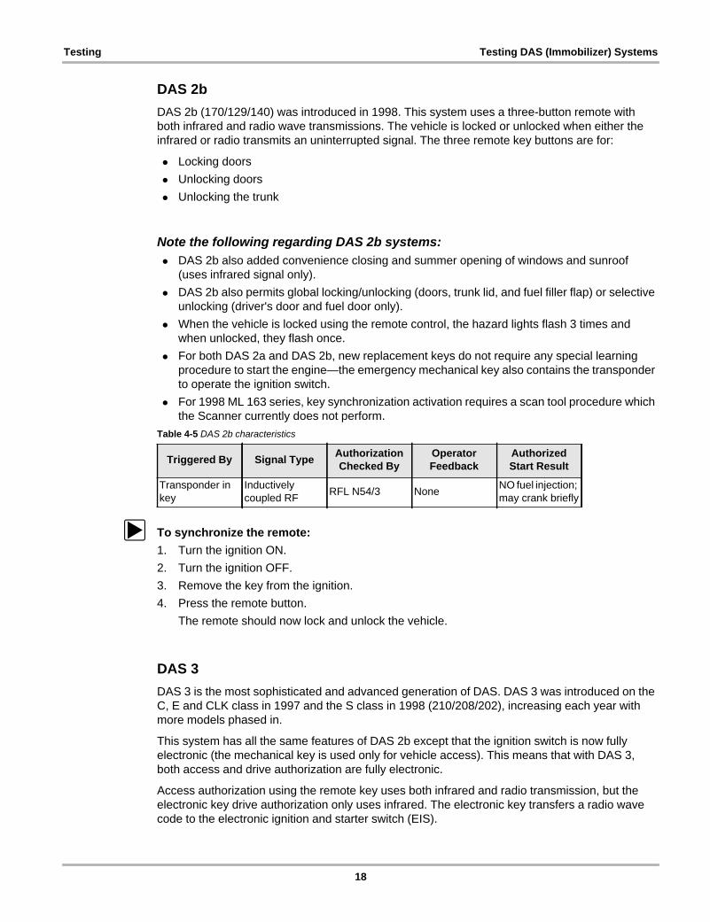
DAS 2bDAS 2b (170/129/140) was introduced in 1998. This system uses a three-button remote with both infrared and radio wave transmissions. The vehicle is locked or unlocked when either the infrared or radio transmits an uninterrupted signal. The three remote key buttons are for:
• Locking doors• Unlocking doors• Unlocking the trunk
Note the following regarding DAS 2b systems:• DAS 2b also added convenience closing and summer opening of windows and sunroof
(uses infrared signal only).• DAS 2b also permits global locking/unlocking (doors, trunk lid, and fuel filler flap) or selective
unlocking (driver's door and fuel door only).• When the vehicle is locked using the remote control, the hazard lights flash 3 times and
when unlocked, they flash once.• For both DAS 2a and DAS 2b, new replacement keys do not require any special learning
procedure to start the engine—the emergency mechanical key also contains the transponder to operate the ignition switch.
• For 1998 ML 163 series, key synchronization activation requires a scan tool procedure which the Scanner currently does not perform.
z To synchronize the remote:1. Turn the ignition ON.2. Turn the ignition OFF.3. Remove the key from the ignition.4. Press the remote button.
The remote should now lock and unlock the vehicle.
DAS 3DAS 3 is the most sophisticated and advanced generation of DAS. DAS 3 was introduced on the C, E and CLK class in 1997 and the S class in 1998 (210/208/202), increasing each year with more models phased in.
This system has all the same features of DAS 2b except that the ignition switch is now fully electronic (the mechanical key is used only for vehicle access). This means that with DAS 3, both access and drive authorization are fully electronic.
Access authorization using the remote key uses both infrared and radio transmission, but the electronic key drive authorization only uses infrared. The electronic key transfers a radio wave code to the electronic ignition and starter switch (EIS).
Table 4-5 DAS 2b characteristics
Triggered By Signal Type Authorization Checked By
Operator Feedback
Authorized Start Result
Transponder in key
Inductively coupled RF RFL N54/3 None NO fuel injection;
may crank briefly
18

Testing Testing DAS (Immobilizer) Systems
Note the following when working on DAS 3 systems:• The electronic key is completely separate from the remote key access system and does not
require the transmitter battery of the remote control. Instead, it is powered by the EIS, which means that the electronic key can be used to start the vehicle even if the remote control battery is dead.
• The side of the electronic key also contains a slide out emergency mechanical key which allows access to the vehicle if the remote battery is dead. It also can be used to lock the glove compartment and the trunk.
• The engine control unit (ECU), electronic shift control module (ESM or EWM) and the electronic ignition control module (EIS) are all locked together permanently.
Workshop Key (Green Key)A special one-time key from the factory may be necessary under the following conditions:
• when cancelling the disablement of a key track• after replacing an ECU that is security-related• after replacing an EIS
For Mercedes Dealers only, a workshop key and EIS are ordered from the factory. The workshop key and EIS must be ordered together. After installation, the workshop key is then inserted into the EIS for final programming. Once this procedure is finished, the workshop key is returned to the factory.
Electronic Steering Lock is optionally available with DAS 3. The steering column is locked and unlocked by means of an electric motor. The control unit of the electric steering lock is directly connected to the electronic ignition (EIS) by the CAN bus, which automatically locks the steering lock when the key is removed and unlocks when the key is inserted. The same setup may be used on an electronic selector lever on some models.
Keyless Go (Optional)The optional Keyless Go replaces the DAS 3 electronic key. The first generation Keyless Go used a chip card carried by the driver which is used to lock or unlock, start and re-lock the vehicle. The engine is started by pressing a start/stop button on the gear selector lever. A button on the chip card can be pressed to check whether the vehicle is locked or unlocked. It can also can be programmed for selective or global locking. The system uses seven frame antennas in the doors and in the rear of the vehicle to determine the position of the Keyless Go chip to know where to unlock or lock. The antennas are also used to know if the chip card is internal or external of the vehicle. This system uses special door handles with pull/push contacts and
Table 4-6 DAS 3 characteristics
Triggered By Signal Type Authorization Checked By
Operator Feedback
Authorized Start Result
Microprocessor in key IR Infrared EIS N73 None
NO fuel injection; NO ignition switch; NO steering lock release
19

Testing Testing DAS (Immobilizer) Systems
capacitive sensors. The 2nd generation Keyless Go no longer uses a separate chip card but has the Keyless Go chip card integrated into the remote key housing.
Note the following with the Keyless Go:• Some Keyless Go vehicles may not have any emergency key door access. In the case of a
dead battery, the emergency key can be used to open trunk to access battery, which can then be charged. The remote key is then used to open the doors.
All DAS VersionsNote the following when testing DAS systems:
• DAS or RCL module replacement means that all of the remote transmitters and transponder keys must be synchronized and version-coded using the factory scan tool.
• The ME control module and either the EIS (DAS 3) or DAS control module are electronically permanently married to each other after 40 engine starts. There is no factory procedure to undo this. This means that a used engine, EIS or DAS control unit cannot be used on another vehicle. A new control unit can be installed for testing provided the 40 engine starts are not exceeded. Note that the new control unit must be variant coded before it can be used. Technicians have reported successfully resetting the counter to 0 on a test ECU at about count 20 by removing the version coding and ECU power for 10 to 30 minutes.
20

Chapter 5 Data Parameters
When DATA is selected, the Scanner displays all of the operating parameters available from the electronic control unit (ECU) of the vehicle. The ECU provides two basic kinds of parameters: digital (or discrete) and analog:
• Digital (discrete) parameters are those that can be in only one of two states, such as on or off, open or closed, high or low, rich or lean, and yes or no. Switches, relays, and solenoids are examples of devices that provide discrete parameters on the data list.
• Analog parameters are displayed as a measured value in the appropriate units. Voltage, pressure, temperature, time, and speed parameters are examples of analog values. The Scanner displays them as numbers that vary through a range of values in units, such as pounds per square inch (psi), kilopascal (kPa), degrees Celsius (°C), degrees Fahrenheit (°F), kilometers per hour (KPH), or miles per hour (MPH).
The Scanner displays some data parameters in numbers that range from 0 to 100, 0 to 255, or 0 to 1800. These ranges are used because in each case, it is the maximum number range that the ECU transmits for a given parameter. However, many parameter readings never reach the highest possible number. For example, you never see a vehicle speed reading of 255 MPH.
For Mercedes-Benz vehicles, the maximum range of a parameter often varies by year, model, and engine. On these applications, the word “variable” appears in the range heading. However, typical sampled values observed under actual test conditions are in the parameter description when available.
Parameters may also be identified as input signals or output commands.
• Input or feedback parameters are signals from various sensors and switches to the ECU. They may be displayed as analog or discrete values, depending upon the input device.
• Output parameters are commands that the ECU transmits to various actuators, such as solenoids and fuel injectors. They are displayed as discrete (ON/OFF parameters, analog values or as a pulse-width modulated (PWM) signal.
In the following section, parameters are presented as they appear on the Scanner screen. Most parameter descriptions are in alphabetical order, but there are exceptions. Often, the same parameter goes by a similar, but different, name when used on more than one model, engine, or control system. In these instances, all of the applicable parameter names, as displayed on the Scanner, are listed in alphabetical order before the description.
To find the description of a parameter, locate it in the alphabetical index, then go to the indicated page. Parameters are listed in the index as they appear on the Scanner screen.
The data parameter descriptions in this manual were created from a combination of sources. For most parameters, some basic information was provided by Mercedes-Benz, then expanded through research and field-testing. Parameter definitions and ranges may expand as more test results become available. For some parameters, no information is currently available.
The Scanner may display names for some data parameters that differ from names displayed by the Mercedes-Benz factory tool and other scan tools.
21

Data Parameters Alphabetical Parameter List
Alphabetical Parameter ListNumerics
3RD GEAR DOWN......................................................................................................................................................... 873RD GEAR UP ............................................................................................................................................................... 874TH GEAR DOWN ......................................................................................................................................................... 874TH GEAR UP................................................................................................................................................................ 875TH GEAR DOWN ......................................................................................................................................................... 875TH GEAR UP................................................................................................................................................................ 875TH GEAR...................................................................................................................................................................... 87
AA/C COMPRESSOR....................................................................................................................................................... 37ABS. INT. MANIF. PRESS. DI1...................................................................................................................................... 37ABS. INT. MANIF. PRESS. DI2...................................................................................................................................... 37ABS. INTAKE MANIFOLD PRESSURE ......................................................................................................................... 37ACCEL. PEDAL POSITION SENSOR ........................................................................................................................... 37ACCELERATION ENRICHMENT................................................................................................................................... 37ACCELERATION SENSOR ........................................................................................................................................... 37ACCELERATOR PEDAL DELAY(%) ............................................................................................................................. 87ACCELERATOR PEDAL(%) .......................................................................................................................................... 87ACTUAL EGR LIFTING SENDER.................................................................................................................................. 37ACTUAL GEAR .............................................................................................................................................................. 87ACTUAL INJECT.QTY. PER STROKE .......................................................................................................................... 37ACTUAL INTAKE AIR PRESSURE................................................................................................................................ 37ACTUAL PRESSURE DISTRIB.PIPE ............................................................................................................................ 38ACTUAL SLIDE VALVE ACTUATOR............................................................................................................................. 38ACTUAL VALUE POT.METER VOLTAGE..................................................................................................................... 38ACTUATOR ACT.VALUE POT.METER R1 ................................................................................................................... 38ACTUATOR ACT.VALUE POT.METER R2 ................................................................................................................... 38ACTUATOR OUTPUT VALUE ....................................................................................................................................... 38ACTUATOR SIGNAL 1................................................................................................................................................... 38ACTUATOR SIGNAL 2................................................................................................................................................... 38ADAPT. RANGE 2 GEAR, 6000-3000 ........................................................................................................................... 39ADAPT. RANGE 2 GEAR, 6000-4000 ........................................................................................................................... 39ADAPT. RANGE 4 GEAR, 2500-1500 ........................................................................................................................... 39ADAPTATION TORQUE (Nm) ....................................................................................................................................... 87ADAPTATION TORQUE DEVIATION (Nm)................................................................................................................... 87ADAPTED RANGES L1 ................................................................................................................................................. 39ADAPTED RANGES L2 ................................................................................................................................................. 39ADAPTED RANGES L3 ................................................................................................................................................. 39ADJUST. CAMSHAFT TIMING SOLENOID................................................................................................................... 39ADR ACTIVE .................................................................................................................................................................. 39ADR RPM ADJUSTMENT.............................................................................................................................................. 39AFTER-START ENRICHMENT...................................................................................................................................... 39AIR CONDITIONING ...................................................................................................................................................... 39AIR FLAP SWITCHOVER ANGLE ................................................................................................................................. 39AIR FLAP........................................................................................................................................................................ 39AIR LOGIC CHAIN ......................................................................................................................................................... 40AIR MASS ...................................................................................................................................................................... 40AIR PUMP ACTIVATION................................................................................................................................................ 40AIR PUMP SWITCHOVER VALVE ................................................................................................................................ 40
22

Data Parameters Alphabetical Parameter List
AIR PUMP SWITCHOVER VALVE, LEFT ..................................................................................................................... 40AIR PUMP SWITCHOVER VALVE, RIGHT ................................................................................................................... 40AIR PUMP ...................................................................................................................................................................... 40ALTITUDE FACTOR (%)................................................................................................................................................ 88ALTITUDE PRESSURE ................................................................................................................................................. 41AMBIENT PRESSURE................................................................................................................................................... 41ASR INTERVENTION .................................................................................................................................................... 41
BBAROMETRIC PRESSURE........................................................................................................................................... 41BASIC INJECTION DURATION ..................................................................................................................................... 41BATTERY VOLTAGE ..................................................................................................................................................... 41BOOST PRESSURE CONTROL.................................................................................................................................... 41BOOST PRESSURE ...................................................................................................................................................... 41BRAKE LAMP SWITCH VIA CAN .................................................................................................................................. 41BRAKE SWITCH ............................................................................................................................................................ 42
CCAMSHAFT ADJUSTMENT VALVE, LEFT ................................................................................................................... 42CAMSHAFT ADJUSTMENT VALVE, RIGHT................................................................................................................. 42CAMSHAFT ADJUSTMENT........................................................................................................................................... 42CAMSHAFT CONTROL LOGIC CHAIN......................................................................................................................... 42CAMSHAFT CONTROL ................................................................................................................................................. 42CAMSHAFT HALL-EFFECT SENSOR .......................................................................................................................... 42CAMSHAFT REFERENCE MARK SIGNAL ................................................................................................................... 42CAMSHAFT SIGNAL, LEFT BANK ................................................................................................................................ 43CAMSHAFT SIGNAL, RIGHT BANK.............................................................................................................................. 43CAMSHAFT SOLENOID ................................................................................................................................................ 42CAMSHAFT SOLENOID ................................................................................................................................................ 43CAMSHAFT TIMING ...................................................................................................................................................... 42CAN DATA EXCHANGE ................................................................................................................................................ 43CAN RECEPTION FROM ASR ...................................................................................................................................... 43CAN RECEPTION FROM DAS ...................................................................................................................................... 43CAN RECEPTION FROM DI1........................................................................................................................................ 43CAN RECEPTION FROM DI2........................................................................................................................................ 43CAN RECEPTION FROM EA,CC,ISC ........................................................................................................................... 43CAN RECEPTION FROM LH1-SFI ................................................................................................................................ 44CAN RECEPTION FROM LH2-SFI ................................................................................................................................ 44CAN TRANSMISSION FROM DI1 ................................................................................................................................. 44CAN TRANSMISSION FROM DI2 ................................................................................................................................. 44CAN TRANSMISSION FROM LH1-SFI.......................................................................................................................... 44CAN TRANSMISSION FROM LH2-SFI.......................................................................................................................... 44CANISTER PURGE DUTY CYCLE................................................................................................................................ 44CANISTER PURGE VALVE DUTY CYCLE ................................................................................................................... 44CATALYST SELECTED ................................................................................................................................................. 44CATALYTIC CONVERTER HEATER............................................................................................................................. 44CHARCOAL CANISTER ................................................................................................................................................ 44CHECK ENGINE AFTER FULFILLING FAULT SEQUENCE ........................................................................................ 45CIRCUIT 15 .................................................................................................................................................................... 45CIRCUIT 50 INPUT ........................................................................................................................................................ 45CIRCUIT 50 OUTPUT .................................................................................................................................................... 45CIRCUIT 50 .................................................................................................................................................................... 45
23

Data Parameters Alphabetical Parameter List
CLUTCH DEPRESSED.................................................................................................................................................. 45CLUTCH SWITCH.......................................................................................................................................................... 45CNTRL VALVE CURRENT-MP(current)(ma)................................................................................................................. 88CNTRL VALVE CURRENT-MP(nominal)(ma) ............................................................................................................... 88CNTRL VALVE CURRENT-SP(current)(ma) ................................................................................................................. 88CNTRL VALVE CURRENT-SP(nominal)(ma) ................................................................................................................ 88COIL FAULT COUNTER T1/1 CYL. 1/4......................................................................................................................... 45COIL FAULT COUNTER T1/1 CYL. 2/5......................................................................................................................... 45COIL FAULT COUNTER T1/2 CYL. 2/3......................................................................................................................... 45COIL FAULT COUNTER T1/2 CYL. 3/4......................................................................................................................... 45COIL FAULT COUNTER T1/3 CYL. 1/6......................................................................................................................... 45COIL SPARK DURAT. T1/1 CYL. 1/4 ............................................................................................................................ 46COIL SPARK DURAT. T1/1 CYL. 2/5 ............................................................................................................................ 46COIL SPARK DURAT. T1/2 CYL. 2/3 ............................................................................................................................ 46COIL SPARK DURAT. T1/2 CYL. 3/4 ............................................................................................................................ 46COIL SPARK DURAT. T1/3 CYL. 1/6 ............................................................................................................................ 46COIL SPARK VOLTAGE T1/1 CYL. 1/4......................................................................................................................... 46COIL SPARK VOLTAGE T1/1 CYL. 2/5......................................................................................................................... 46COIL SPARK VOLTAGE T1/2 CYL. 2/3......................................................................................................................... 46COIL SPARK VOLTAGE T1/2 CYL. 3/4......................................................................................................................... 46COIL SPARK VOLTAGE T1/3 CYL. 1/6......................................................................................................................... 46COMBUSTION TIME CYL. 1.......................................................................................................................................... 46COMBUSTION TIME CYL. 2.......................................................................................................................................... 46COMBUSTION TIME CYL. 3.......................................................................................................................................... 46COMBUSTION TIME CYL. 4.......................................................................................................................................... 46COMBUSTION TIME CYL. 5.......................................................................................................................................... 46COMBUSTION TIME CYL. 6.......................................................................................................................................... 46COMBUSTION TIME CYL. 7.......................................................................................................................................... 46COMBUSTION TIME CYL. 8.......................................................................................................................................... 46COMPRESSOR CLUTCH .............................................................................................................................................. 46COMPRESSOR EFFICIENCY FACTOR ....................................................................................................................... 46CONVERSION ............................................................................................................................................................... 89CONVERTED TORQUE (Nm)........................................................................................................................................ 89COOL.FAN OUTP.DEMAND CLIMATE CTRL............................................................................................................... 47COOL.FAN OUTP.DEMAND.BY CLIM.CTRL................................................................................................................ 47COOL.FAN OUTP.DEMANDED BY ENGINE ................................................................................................................ 47COOLANT TEMPERATURE .......................................................................................................................................... 47COOLING FAN OUTPUT DEMAND ENGINE................................................................................................................ 47CORRECTED INT.MANIFOLD PRESS ......................................................................................................................... 47CR. CTRL SHUT-OFF BRAKES APPLIED .................................................................................................................... 47CRANKSHAFT MAGNET CODING ............................................................................................................................... 47CRANKSHAFT SEGMENT ORDER .............................................................................................................................. 47CRUISE CONTROL ENGAGED .................................................................................................................................... 47CRUISE CONTROL LEVER POSITION VARIABLE...................................................................................................... 48CRUISE CONTROL LEVER SIGNAL IMPLAUSIBLE.................................................................................................... 48CRUISE CONTROL OFF ............................................................................................................................................... 48CRUISE CONTROL RESTART...................................................................................................................................... 48CRUISE CONTROL SET AND ACCELERATE.............................................................................................................. 48CRUISE CONTROL SET AND DECELERATE.............................................................................................................. 48CRUISE CONTROL SHUT-OFF FUNCTION................................................................................................................. 48CRUISE CONTROL SHUT-OFF SAFETY ..................................................................................................................... 48CRUISE CONTROL SWITCH A..................................................................................................................................... 48CRUISE CONTROL SWITCH ACCELERATE ............................................................................................................... 48
24

Data Parameters Alphabetical Parameter List
CRUISE CONTROL SWITCH B..................................................................................................................................... 48CRUISE CONTROL SWITCH DECELERATE ............................................................................................................... 48CRUISE CONTROL SWITCH ........................................................................................................................................ 48CRUISE CONTROL ....................................................................................................................................................... 47CRUISE CONTROL/SPEED LIMITER INTERVENT...................................................................................................... 48CSO, IDLE F.TRIM CYL.10-12, LEFT............................................................................................................................ 48CSO, IDLE F.TRIM CYL.1-3, RIGHT ............................................................................................................................. 48CSO, IDLE F.TRIM CYL.4-6, RIGHT ............................................................................................................................. 48CSO, IDLE F.TRIM CYL.7-9, LEFT................................................................................................................................ 48CSO, LOW.P.LOAD F.TRIM CYL 10-12, LEFT ............................................................................................................. 49CSO, LOW.P.LOAD F.TRIM CYL 1-3, RIGHT ............................................................................................................... 49CSO, LOW.P.LOAD F.TRIM CYL 4-6, RIGHT ............................................................................................................... 49CSO, LOW.P.LOAD F.TRIM CYL 7-9, LEFT ................................................................................................................. 49CTP (IDLE) ADJUSTMENT VALUE ............................................................................................................................... 49CTP (IDLE) CONTACT................................................................................................................................................... 49CTP (IDLE) INFORMATION........................................................................................................................................... 49CTP (IDLE) LONG-TERM ADAPT. VALUES ................................................................................................................. 49CTP (IDLE) RECOGNITION........................................................................................................................................... 49CTP (IDLE) ..................................................................................................................................................................... 49CYL. 1 to 12.................................................................................................................................................................... 49CYLINDER SHUT-OFF 1 to 12 ...................................................................................................................................... 50CYLINDER SHUT-OFF VALVE, LEFT........................................................................................................................... 50CYLINDER SHUT-OFF VALVE, RIGHT ........................................................................................................................ 50
DDAS AND DSV MODULES ARE MATCHED ................................................................................................................. 50DAS AND ECM COMPATIBLE ...................................................................................................................................... 50DAS AND ENGINE CTRL. MOD. COMPATIBLE........................................................................................................... 50DAS CONTROL MODULES........................................................................................................................................... 50DECELERATION SHUT-OFF ........................................................................................................................................ 50DECELERATION............................................................................................................................................................ 50DECELERATION(%) ...................................................................................................................................................... 89DELAY (DOWNSHIFT)................................................................................................................................................... 89DELAY (UPSHIFT) ......................................................................................................................................................... 89DESIRED ENGINE SPEED............................................................................................................................................ 51DESIRED GEAR ............................................................................................................................................................ 89DISTRIBUTOR SHAFT ACTUAL POS........................................................................................................................... 51DISTRIBUTOR SHAFT NOMINAL POS. ....................................................................................................................... 51DRIVE AUTH. RCL & ECM COMPATIBLE .................................................................................................................... 51DRIVE AUTHORIZ.,IMMOBOLIZER .............................................................................................................................. 51DRIVE PROGRAM SWITCH.......................................................................................................................................... 89DRIVER GIVEN TORQUE ............................................................................................................................................. 51DRIVER STATUS INFORMATION................................................................................................................................. 89DWELL TIME, CYLINDER 1 to 12 ................................................................................................................................. 51
EEBR INTERVENTION .................................................................................................................................................... 51ECM IDENTIFIED........................................................................................................................................................... 51ECM LOCKED................................................................................................................................................................ 51ECT LH1......................................................................................................................................................................... 52ECT LH2......................................................................................................................................................................... 52ECT OPERATING TEMPERATURE .............................................................................................................................. 52
25

Data Parameters Alphabetical Parameter List
ECT SENSOR ................................................................................................................................................................ 52ECT VALUE RANGE...................................................................................................................................................... 52EFFECT.COOL.FAN OUTPUT DUTY CYCLE............................................................................................................... 52EGR ACTIVATION ......................................................................................................................................................... 52EGR LOGIC CHAIN ....................................................................................................................................................... 52EGR LOGIC CHAIN ....................................................................................................................................................... 52EGR VALVE ................................................................................................................................................................... 52EGR VALVE ................................................................................................................................................................... 52EGR................................................................................................................................................................................ 52EGR................................................................................................................................................................................ 52ELECTRIC AIR PUMP ................................................................................................................................................... 53ELECTRIC COOLING FAN ............................................................................................................................................ 53ENGINE BRAKE TORQUE ............................................................................................................................................ 53ENGINE CONTROL MODULE IDENTIFIED.................................................................................................................. 51ENGINE CONTROL MODULE LOCKED ....................................................................................................................... 51ENGINE CONTROL MODULE OR CAN-BUS ............................................................................................................... 58ENGINE COOLANT TEMP. 1 ........................................................................................................................................ 52ENGINE COOLANT TEMP. 2 ........................................................................................................................................ 52ENGINE COOLANT TEMPERATURE(°) ....................................................................................................................... 53ENGINE COOLANT TEMPERATURE(V) ...................................................................................................................... 53ENGINE LOAD ............................................................................................................................................................... 53ENGINE OIL LEVEL....................................................................................................................................................... 54ENGINE OIL TEMPERATURE....................................................................................................................................... 54ENGINE RUN TIME LONG TERM MONITOR ............................................................................................................... 90ENGINE RUN TIME SHORT TERM MONITOR............................................................................................................. 90ENGINE SPEED (1/MIN)................................................................................................................................................ 90ENGINE SPEED LIMITER ............................................................................................................................................. 54ENGINE SPEED............................................................................................................................................................. 54ENGINE START CONTROL .......................................................................................................................................... 54ENGINE START TEMPERATURE................................................................................................................................. 54ENGINE TORQUE ......................................................................................................................................................... 90ETS INTERVENTION..................................................................................................................................................... 54ETS INTERVENTION..................................................................................................................................................... 54ETS................................................................................................................................................................................. 54EXHAUST GAS TEMPERATURE.................................................................................................................................. 55EXHAUST TEMPERATURE (TWC MODEL) ................................................................................................................. 55EXHAUST TEMPERATURE LEFT................................................................................................................................. 55EXHAUST TEMPERATURE RIGHT .............................................................................................................................. 55
FFAN CAPACITY REQUEST BY A/C .............................................................................................................................. 55FAN CAPACITY REQUEST BY ENGINE ...................................................................................................................... 55FAN CAPACITY, EFFECTIVE........................................................................................................................................ 55FILL CORRECTION TIME (CYCLE) .............................................................................................................................. 90FILL MEASUREMENT TIME (CYCLE) .......................................................................................................................... 90FRICTIONAL OUTPUT .................................................................................................................................................. 90FRONT AXLE SPEED.................................................................................................................................................... 55FRONT AXLE SPEED.................................................................................................................................................... 90FUEL CANISTER PRESSURE DIFF. ............................................................................................................................ 55FUEL LEVEL .................................................................................................................................................................. 55FUEL PUMP ................................................................................................................................................................... 55FUEL RACK POSITION ................................................................................................................................................. 56FUEL RACK TRAVEL .................................................................................................................................................... 55
26

Data Parameters Alphabetical Parameter List
FUEL TANK CAP ........................................................................................................................................................... 56FUEL TANK LEVEL........................................................................................................................................................ 56FUEL TEMPERATURE .................................................................................................................................................. 56FULL LOAD DETECTION .............................................................................................................................................. 56FUNCTION FAULT......................................................................................................................................................... 56
GG/S PROGRAM SELECTION SWITCH ......................................................................................................................... 89GEAR COMPARISON COUNTER ................................................................................................................................. 90GRADE(%) ..................................................................................................................................................................... 90
HHFM VOLTAGE.............................................................................................................................................................. 56HFM-SFI MAP ................................................................................................................................................................ 57HOLD GEAR .................................................................................................................................................................. 57HOLD GEAR .................................................................................................................................................................. 91HOT FILM MASS AIR FLOW SENSOR ......................................................................................................................... 56HOT FILM MASS AIR FLOW SENSOR ......................................................................................................................... 57HOT FILM VOLTAGE..................................................................................................................................................... 56HOT WIRE AIR MASS ................................................................................................................................................... 57HOT WIRE VOLTAGE.................................................................................................................................................... 56
IIDLE FUEL TRIM ADAPTAT. RIGHT............................................................................................................................. 57IDLE FUEL TRIM ADAPTATION LEFT.......................................................................................................................... 57IDLE FUEL TRIM CYL. 10-12 LEFT............................................................................................................................... 57IDLE FUEL TRIM CYL. 1-3 RIGHT ................................................................................................................................ 57IDLE FUEL TRIM CYL. 4-6 RIGHT ................................................................................................................................ 57IDLE FUEL TRIM CYL. 7-9 LEFT................................................................................................................................... 57IDLE SPEED CONTROL................................................................................................................................................ 57IDLE SPEED DETECTION............................................................................................................................................. 57IDLE SPEED RECOGNITION ........................................................................................................................................ 57IFI/DFI RECEIVING FROM ETC (722.6)........................................................................................................................ 58IFI/DFI RECEIVING FROM ETS/ABS ............................................................................................................................ 58IFI/DFI RECEIVING FROM ETS/ABS/ASR.................................................................................................................... 58IFI/DFI RECEIVING MESSAGE 1 FROM IC.................................................................................................................. 58IFI/DFI RECEIVING MESSAGE 2 FROM IC.................................................................................................................. 58IFI/DFI TRANSM. TO ASR/ESP/ A/C /ETC.................................................................................................................... 58IFI/DFI TRANSM. TO IC/ASR/ETC (722.6).................................................................................................................... 58IFI/DFI TRANSMITTING TO ETC/ASR .......................................................................................................................... 58IFI/DFI TRANSMITTING TO ETC/IC.............................................................................................................................. 58IGNITION ADVANCE ANGLE ........................................................................................................................................ 58IGNITION ANGLE .......................................................................................................................................................... 58IGNITION FAULT COUNTER CYL. 1 ............................................................................................................................ 58IGNITION FAULT COUNTER CYL. 2 ............................................................................................................................ 58IGNITION FAULT COUNTER CYL. 3 ............................................................................................................................ 58IGNITION FAULT COUNTER CYL. 4 ............................................................................................................................ 58IGNITION FAULT COUNTER CYL. 5 ............................................................................................................................ 58IGNITION FAULT COUNTER CYL. 6 ............................................................................................................................ 58IGNITION FIRING POINT CYLINDER 1 ........................................................................................................................ 58IGNITION VOLTAGE CYL. 1 to 12................................................................................................................................. 58IMMOBILIZER STATUS ................................................................................................................................................. 58
27

Data Parameters Alphabetical Parameter List
INCREASED MODULATING PRESS.STATUS ............................................................................................................. 91INDICATED ENGINE TORQUE ..................................................................................................................................... 58INDUCED TORQUE(Nm)............................................................................................................................................... 91INERTIA FUEL SHUTOFF ............................................................................................................................................. 59INJECTION DURATION CORRECTION........................................................................................................................ 59INJECTION DURATION LEFT ....................................................................................................................................... 59INJECTION DURATION RIGHT..................................................................................................................................... 59INJECTION DURATION................................................................................................................................................. 59INJECTION LONG-TERM ADAPTATION ...................................................................................................................... 59INJECTION SHORT-TERM ADAPTATION.................................................................................................................... 59INJECTION SHUT-OFF CYLINDER 1 to 12 .................................................................................................................. 60INJECTION SYSTEM..................................................................................................................................................... 59INJECTION TIME ADV. TRAVEL................................................................................................................................... 59INJECTION TIME ........................................................................................................................................................... 59INJECTION TIME, CYLINDER 1 to 3............................................................................................................................. 60INJECTION TIME, CYLINDER 10 to 12......................................................................................................................... 60INJECTION TIME, CYLINDER 4 to 6............................................................................................................................. 60INJECTION TIME, LEFT BANK ..................................................................................................................................... 60INJECTION TIME, RIGHT BANK ................................................................................................................................... 60INJECTOR ACTIVATION ............................................................................................................................................... 59INJECTOR...................................................................................................................................................................... 59INTAKE AIR TEMPERATURE ....................................................................................................................................... 60INTAKE MANIFOLD ABS. PRESSURE ......................................................................................................................... 60INTAKE MANIFOLD SW.-OVER VALVE ....................................................................................................................... 60INTAKE MANIFOLD ....................................................................................................................................................... 60IRREGULAR RUNNING SHUTOFF VALUE .................................................................................................................. 61IRREGULAR RUNNING SHUTOFF VALUE .................................................................................................................. 61IRREGULAR RUNNING................................................................................................................................................. 61
KKICK DOWN SWITCH.................................................................................................................................................... 91KICK DOWN................................................................................................................................................................... 91KICKDOWN SWITCH..................................................................................................................................................... 61KICKDOWN.................................................................................................................................................................... 61KNOCK CONTROL ACTIVE .......................................................................................................................................... 61KNOCK CONTROL APPROVAL.................................................................................................................................... 61KNOCK CONTROL LEFT .............................................................................................................................................. 61KNOCK CONTROL RIGHT ............................................................................................................................................ 61KNOCK CONTROL ........................................................................................................................................................ 61KNOCK IGNITION ANGLE CYL. 1 to 12........................................................................................................................ 61KNOCK IGNITION ANGLE CYL. 1 to 8.......................................................................................................................... 61KNOCK SENSOR CYLINDER 1 to 4 ............................................................................................................................. 62KNOCK SENSOR EVALUATION................................................................................................................................... 62KNOCK SENSOR FRONT ............................................................................................................................................. 62KNOCK SENSOR LEFT FRONT ................................................................................................................................... 62KNOCK SENSOR LEFT REAR...................................................................................................................................... 62KNOCK SENSOR LEFT................................................................................................................................................. 62KNOCK SENSOR REAR................................................................................................................................................ 62KNOCK SENSOR RIGHT FRONT ................................................................................................................................. 62KNOCK SENSOR RIGHT REAR ................................................................................................................................... 62KNOCK SENSOR RIGHT .............................................................................................................................................. 62KNOCK SENSOR SIGNALS .......................................................................................................................................... 62KNOCK SENSOR........................................................................................................................................................... 62
28

Data Parameters Alphabetical Parameter List
KNOCK SIGNAL............................................................................................................................................................. 62
LLAMBDA CONTROL ACTIVE ........................................................................................................................................ 62LAMBDA, UPSTREAM CAT, CYL 1 to 12...................................................................................................................... 62LAMBDA, UPSTREAM CAT, LEFT................................................................................................................................ 62LAMBDA, UPSTREAM CAT, RIGHT ............................................................................................................................. 62LE ACTUATOR ACT.VALUE POT.MTR R1................................................................................................................... 62LE ACTUATOR ACT.VALUE POT.MTR R2................................................................................................................... 62LEAN/RICH RESPONSE TIME...................................................................................................................................... 63LEARN VALUE THROTTLE VALVE STOP ................................................................................................................... 63LEFT FRONT VSS ......................................................................................................................................................... 63LEFT O2S (LAMBDA) CONTROL ACTIVE.................................................................................................................... 63LEFT O2S (LAMBDA) CONTROL AUTHORIZED ......................................................................................................... 63LEFT O2S (LAMBDA) CONTROL FAULT ..................................................................................................................... 63LEFT O2S (LAMBDA) CONTROL W/O O2S2 ............................................................................................................... 63LEFT WOT (FULL LOAD)/DECEL.SHUT-OFF .............................................................................................................. 64LEVER POSITION ACCELERATE................................................................................................................................. 64LEVER POSITION DECELERATE................................................................................................................................. 64LEVER POSITION OFF ................................................................................................................................................. 64LH-SFI REF. RESISTOR................................................................................................................................................ 64LIMP-HOME ................................................................................................................................................................... 91LOAD CORRECTION FACTOR..................................................................................................................................... 64LOAD.............................................................................................................................................................................. 64LOW RANGE PROGRAM .............................................................................................................................................. 92LOW VOLTAGE ............................................................................................................................................................. 64LOWER P. LOAD F. TRIM CYL 10-12, LEFT ................................................................................................................ 65LOWER P. LOAD F. TRIM CYL 1-6, RIGHT.................................................................................................................. 65LOWER P. LOAD F. TRIM CYL 4-6, RIGHT.................................................................................................................. 65LOWER P. LOAD F. TRIM CYL 7-9, LEFT .................................................................................................................... 65LR VSS (1/MIN).............................................................................................................................................................. 92LR VSS........................................................................................................................................................................... 65
MM39(RECIR. AIR FLAP ACT.)VOLT.1 ........................................................................................................................... 65M39(RECIR. AIR FLAP ACT.)VOLT.2 ........................................................................................................................... 65MANIFOLD ABS. PRESSURE (MAP)............................................................................................................................ 65MANIFOLD AIR PRESSURE DIFF ................................................................................................................................ 65MANIFOLD AIR PRESSURE ......................................................................................................................................... 65MAP(%) .......................................................................................................................................................................... 92MASS AIR FLOW SENSOR........................................................................................................................................... 65MAX. INDICATED ENGINE TORQUE ........................................................................................................................... 66MIN. INDICATED ENGINE TORQUE ............................................................................................................................ 66MISF.RECOGN. SH-OFF THRESHLD .......................................................................................................................... 66MISFIRE COUNTER CYLINDER 1 to 4 ......................................................................................................................... 66MISFIRE CYLINDER 1 to 12.......................................................................................................................................... 66MISFIRE CYLINDER 1 to 8............................................................................................................................................ 66MISFIRE FAULT COUNTER CYLINDER 1 to 12........................................................................................................... 66MIXTURE ADAPTATION ............................................................................................................................................... 66MULTIPLE COMBUST MISF. EMISS. LIM. ................................................................................................................... 66MULTIPLE COMBUST MISF. I/M PROGR. ................................................................................................................... 66MULTIPLE COMBUST MISF. TWC PROT. ................................................................................................................... 66
29

Data Parameters Alphabetical Parameter List
MULTIPLE IGN. MISF. TWC PROTECT........................................................................................................................ 66MULTIPLE IGN. MISFIRE EMISS. LIM.......................................................................................................................... 66MULTIPLE IGN. MISFIRE I/M PROGR.......................................................................................................................... 66MULTIPLE MAP ADJUSTMENT ACTIVE ...................................................................................................................... 66
NNOM. PRESS. TORQ. CONV. LOCK-UP(MBAR) ......................................................................................................... 92NOMINAL AIR MASS ..................................................................................................................................................... 66NOMINAL ENGINE SPEED ........................................................................................................................................... 67NOMINAL FUEL RACK TRAVEL ................................................................................................................................... 67NOMINAL INJ. TIM. ADV. TRAVEL ............................................................................................................................... 67NOMINAL MANIFOLD ABSOL. PRESS. ....................................................................................................................... 67NOMINAL PRESSURE DISTRIB. PIPE ......................................................................................................................... 67NOMINAL SLIDE VALVE ACTUATOR .......................................................................................................................... 67NOMINAL START OF INJECTION ................................................................................................................................ 67NOMINAL VEHICLE SPEED.......................................................................................................................................... 67NUMBER OF STARTS WITH NON-LOCKED ECM....................................................................................................... 67
OO2 CONTROL DOWNSTREAM CAT, CYL 1-3;4-6;7-9;10-12....................................................................................... 67O2 CONTROL UPSTREAM CAT, CYL 1-3;4-6;7-9;10-12 ............................................................................................. 67O2 CONTROL, DOWNSTREAM CAT, LEFT................................................................................................................. 67O2 CONTROL, DOWNSTREAM CAT, RIGHT .............................................................................................................. 67O2 CONTROL, UPSTREAM CAT, LEFT ....................................................................................................................... 67O2 CONTROL, UPSTREAM CAT, RIGHT..................................................................................................................... 67O2 SENSOR, DOWNSTREAM CAT .............................................................................................................................. 68O2 SENSOR, DOWNSTREAM CAT, CYL 1-3; 4-6; 7-9; 10-12 ..................................................................................... 68O2 SENSOR, DOWNSTREAM CAT, LEFT ................................................................................................................... 68O2 SENSOR, DOWNSTREAM CAT, RIGHT................................................................................................................. 68O2 SENSOR, UPSTREAM CAT, CYL 1-3; 4-6; 7-9; 10-12............................................................................................ 68O2 SENSOR, UPSTREAM CATO2 SENSOR, UPSTREAM CAT, LEFTO2 SENSOR, UPSTREAM CAT, RIGHT ....................................................................................................................... 68O2S (LAMBDA) CONTROL AFTER TWC...................................................................................................................... 68O2S (LAMBDA) CONTROL AFTER TWC...................................................................................................................... 70O2S (LAMBDA) CONTROL APPROVED....................................................................................................................... 68O2S (LAMBDA) CONTROL BEFORE TWC................................................................................................................... 68O2S (LAMBDA) CONTROL............................................................................................................................................ 68O2S (LAMBDA) CTRL AFT. TWC LEFT ........................................................................................................................ 70O2S (LAMBDA) CTRL AFT. TWC RIGHT...................................................................................................................... 70O2S (LAMBDA) CTRL BEF. TWC RIGHT ..................................................................................................................... 68O2S (LAMBDA) CTRL BEFORE TWC LEFT ................................................................................................................. 68O2S (LAMBDA) CTRL CTP (IDLE) MEAN..................................................................................................................... 69O2S (LAMBDA) CTRL PART. LOAD MEAN .................................................................................................................. 69O2S (LAMBDA)CTRL AFT. TWC LEFT ......................................................................................................................... 68O2S (LAMBDA)CTRL AFT.TWC RIGHT........................................................................................................................ 68O2S 1 (BEFORE TWC) HEATER .................................................................................................................................. 69O2S 1 HEATER.............................................................................................................................................................. 69O2S 1 VOLTAGE ........................................................................................................................................................... 69O2S 2 HEATER.............................................................................................................................................................. 69O2S 2 VOLTAGE ........................................................................................................................................................... 69O2S CONT.SHIFT MILEAGE COUNTER ...................................................................................................................... 69
30

Data Parameters Alphabetical Parameter List
O2S CONTROL, UPSTREAM CAT(%) .......................................................................................................................... 68O2S DOWNSTREAM CAT, CYL 1 to 12........................................................................................................................ 69O2S DOWNSTREAM CAT, LEFT .................................................................................................................................. 69O2S DOWNSTREAM CAT, RIGHT................................................................................................................................ 69O2S HEATER AFTER TWC........................................................................................................................................... 69O2S HEATER BEFORE TWC........................................................................................................................................ 69O2S UPSTREAM CAT, CYL 1 to 12 .............................................................................................................................. 69O2S UPSTREAM CAT, LEFT ........................................................................................................................................ 69O2S UPSTREAM CAT, RIGHT ...................................................................................................................................... 69O2S VOLTAGE AFTER TWC LEFT............................................................................................................................... 70O2S VOLTAGE AFTER TWC RIGHT ............................................................................................................................ 70O2S VOLTAGE AFTER TWC ........................................................................................................................................ 70O2S VOLTAGE BEFORE TWC LEFT............................................................................................................................ 70O2S VOLTAGE BEFORE TWC RIGHT ......................................................................................................................... 70O2S VOLTAGE BEFORE TWC ..................................................................................................................................... 70O2S VOLTAGE .............................................................................................................................................................. 70OIL CONDITION LONG TERM MONITOR .................................................................................................................... 92OIL CONDITION SHORT TERM MONITOR.................................................................................................................. 92OIL LEVEL SWITCH ...................................................................................................................................................... 70OIL LEVEL...................................................................................................................................................................... 70OIL QUALITY ................................................................................................................................................................. 70OIL TEMPERATURE...................................................................................................................................................... 70ON OFF RATIO/O2S (LAMBDA) CONTROL(%) ........................................................................................................... 70OPERATING ACTUAL RPM .......................................................................................................................................... 67OPERATING NOMINAL RPM ........................................................................................................................................ 67OPTIMAL CALC. MOD. PRESSURE(MBAR) ................................................................................................................ 92OPTIMAL CALC. SHIFT PRESSURE(MBAR) ............................................................................................................... 92OUTPUT DEMAND DUTY CYCLE ................................................................................................................................ 71OUTPUT DEMAND DUTY CYCLE(%)........................................................................................................................... 71OUTPUT SHAFT SPEED (1/MIN).................................................................................................................................. 92OUTPUT SHAFT SPEED............................................................................................................................................... 71OXYGEN SENSOR (O2S) ............................................................................................................................................. 71
PP/N RECOGNIZED......................................................................................................................................................... 71P/N RECOGNIZED......................................................................................................................................................... 93PARKING BRAKE .......................................................................................................................................................... 71PART LOAD FUEL TRIM ADAPTAT. LEFT................................................................................................................... 71PART LOAD FUEL TRIM ADAPTAT. RIGHT ................................................................................................................ 71PEDAL VALUE SENSOR SIGNAL 1.............................................................................................................................. 72PEDAL VALUE SENSOR SIGNAL 2.............................................................................................................................. 72PEDAL VALUE SNSR REF.POT.MTR R1 ..................................................................................................................... 72PEDAL VALUE SNSR REF.POT.MTR R2 ..................................................................................................................... 72PEDAL VALUE ............................................................................................................................................................... 72PLANET. SPEED SENSOR (N2)(CUR.) ........................................................................................................................ 92PLANET. SPEED SENSOR (N2)(NOM.) ....................................................................................................................... 92PLANET. SPEED SENSOR (N3)(CUR.) ........................................................................................................................ 92PLANET. SPEED SENSOR (N3)(NOM.) ....................................................................................................................... 92PRESSURE CONTROL ................................................................................................................................................. 72PURGE CONTROL ........................................................................................................................................................ 72PURGE FACTOR F 1..................................................................................................................................................... 72PURGE FACTOR F 2..................................................................................................................................................... 72PURGE FACTOR F 3..................................................................................................................................................... 72
31

Data Parameters Alphabetical Parameter List
PURGE FACTOR F 4..................................................................................................................................................... 72PURGE VALVE DUTY CYCLE ...................................................................................................................................... 73PURGING....................................................................................................................................................................... 73PWM SOLENOID VALVE STATUS ............................................................................................................................... 93
RR/P LOCK-OUT OUTPUT .............................................................................................................................................. 93REAR AXLE SPEED ...................................................................................................................................................... 73RECIRCULATED AIR FLAP POSITION ........................................................................................................................ 73RECOGNIZED TRANSMISSION GEAR ........................................................................................................................ 93REFERENCE RESISTOR VOLTAGE ............................................................................................................................ 73REFERENCE RESISTOR .............................................................................................................................................. 73REG. PRESS. TORQ. CONV. LOCK-UP(MBAR) .......................................................................................................... 92RESONANCE FLAP INT. LINE NOM............................................................................................................................. 74RESONANCE FLAP INT. MANIF. ACTUAL................................................................................................................... 74RESONANCE FLAP INT. MANIF. NOMINAL ................................................................................................................ 74RESONANCE FLAP INTAKE PIPE ACTUAL ................................................................................................................ 74RESONANCE FLAP INTAKE PIPE NOMINAL .............................................................................................................. 74RI ACTUATOR ACT.VALUE POT.MTR R1 ................................................................................................................... 74RI ACTUATOR ACT.VALUE POT.MTR R2 ................................................................................................................... 74RIGHT O2S (LAMBDA) CONTROL ACTIVE ................................................................................................................. 74RIGHT O2S (LAMBDA) CONTROL AUTHORIZED ....................................................................................................... 74RIGHT O2S (LAMBDA) CONTROL FAULT ................................................................................................................... 75RIGHT O2S (LAMBDA) CONTROL W/O O2S2 ............................................................................................................. 75RIGHT WOT (FULL LOAD)/DECEL.SHUT-OFF............................................................................................................ 75RON CORRECTION ...................................................................................................................................................... 75RON INDEX.................................................................................................................................................................... 75RR VSS(1/MIN) (RPM)................................................................................................................................................... 93
SSAFETY CONTACT ....................................................................................................................................................... 75SAFETY FUEL SHUT-OFF ............................................................................................................................................ 75SELECTED GEAR ......................................................................................................................................................... 76SELECTOR LEVER POSITION ..................................................................................................................................... 76SELECTOR LEVER POSITION ..................................................................................................................................... 94SELF-ADAPT THROTTLE VALVE-ACT ........................................................................................................................ 76SELF-ADAPT. CTP (IDLE) LEFT ................................................................................................................................... 78SELF-ADAPT. CTP (IDLE) RIGHT................................................................................................................................. 78SELF-ADAPT. DELAY TIME LEFT ................................................................................................................................ 78SELF-ADAPT. DELAY TIME RIGHT.............................................................................................................................. 78SELF-ADAPT. FACTOR LOWER PART. LOAD ............................................................................................................ 78SELF-ADAPT.PART. LOAD FACTOR LEFT ................................................................................................................. 78SELF-ADAPT.PART. LOAD FACTOR RIGHT ............................................................................................................... 78SELF-ADAPTATION CTP (IDLE)................................................................................................................................... 76SELF-ADAPTATION CTP (IDLE)................................................................................................................................... 76SELF-ADAPTATION DELAY TIME ................................................................................................................................ 76SELF-ADAPTATION IDLE SP. AIR................................................................................................................................ 77SELF-ADAPTATION LOWER PART. LOAD.................................................................................................................. 78SELF-ADAPTATION PARTIAL LOAD............................................................................................................................ 77SELF-ADAPTATION PARTIAL LOAD............................................................................................................................ 78SELF-ADAPTATION UPPER PART. LOAD................................................................................................................... 77SELF-ADAPTATION ...................................................................................................................................................... 76
32

Data Parameters Alphabetical Parameter List
SELF-ADAPTATION, IDLE SPEED ............................................................................................................................... 77SELF-ADAPTATION, IDLE SPEED ............................................................................................................................... 77SENSITIZATION FACTOR............................................................................................................................................. 79SENSOR GEAR ADAPTATION ENDED........................................................................................................................ 80SENSOR GEAR FILTER 1............................................................................................................................................. 79SENSOR GEAR FILTER 2............................................................................................................................................. 79SENSOR ROTOR ADAPTATION COMPLETED ........................................................................................................... 79SENSOR ROTOR ADAPTATION .................................................................................................................................. 79SHIFT ABORT................................................................................................................................................................ 94SHIFT APPROVED ........................................................................................................................................................ 94SHIFT DOUBLE ............................................................................................................................................................. 94SHIFT FREQUENCY...................................................................................................................................................... 94SHIFT LINE EVALUATION ............................................................................................................................................ 94SHIFT POINT SHIFT...................................................................................................................................................... 80SHIFT POINT ................................................................................................................................................................. 94SHIFT PRESSURE DEVIATION(MBAR) ....................................................................................................................... 94SHIFT VALVE 1-2/4-5 .................................................................................................................................................... 95SHIFT VALVE 2-3 .......................................................................................................................................................... 95SHIFT VALVE 3-4 .......................................................................................................................................................... 95SHIFT VALVE DUTY CYCLE......................................................................................................................................... 95SLIPPAGE RPM (CUR. VALUE)(1/MIN)........................................................................................................................ 95SLIPPAGE RPM (NOM. VALUE)(1/MIN) ....................................................................................................................... 95SLV DEMAND ................................................................................................................................................................ 95SMOOTH RUNNING OF CYL. 1 to 8 ............................................................................................................................. 80SNSR GEAR ADAPT. MEAN VAL. SEG.A to E; N1 to N4............................................................................................. 80SNSR GEAR ADAPT. MEAN VALUES SEG. A TO E ................................................................................................... 79SNSR GEAR ADAPT. MEAN VALUES SEG.A to E ...................................................................................................... 80SP.DEV.BT. FR/RR AXLES TOO HIGH ........................................................................................................................ 80SPEED DEV. DISENGAGE CLUTCH(1MIN) ................................................................................................................. 96SPEED SIGNAL ............................................................................................................................................................. 80START APPROVAL ....................................................................................................................................................... 81START ATTEMPT MADE WITH DAS LOCKED ............................................................................................................ 81START ATTEMPT W.IMPLAUS.INPUT SIGN ............................................................................................................... 81START AUTHORIZATION ............................................................................................................................................. 81START OF INJECTION.................................................................................................................................................. 81STARTER CONTROL .................................................................................................................................................... 82STARTER CONTROL .................................................................................................................................................... 96STARTER LOCK-OUT OUTPUT ................................................................................................................................... 82STARTER LOCK-OUT OUTPUT ................................................................................................................................... 96STARTER LOCK-OUT REED CONTACT...................................................................................................................... 82STARTER LOCK-OUT REED CONTACT...................................................................................................................... 96STARTER LOCK-OUT STATUS .................................................................................................................................... 82STARTER LOCK-OUT STATUS .................................................................................................................................... 96STARTER SIGNAL CIRCUIT 50 .................................................................................................................................... 82STOP LAMP SWITCH N.C. CONTACT ......................................................................................................................... 82STOP LAMP SWITCH N.O. CONTACT ......................................................................................................................... 82STOP LAMP SWITCH.................................................................................................................................................... 82STOP LAMP SWITCH.................................................................................................................................................... 96SUM EVALUATION........................................................................................................................................................ 96SUPERCHARGER CLUTCH.......................................................................................................................................... 82SUPERCHARGER EFFICIENCY FACTOR ................................................................................................................... 82
33

Data Parameters Alphabetical Parameter List
TTANK FILL LEVEL.......................................................................................................................................................... 82TANK PRESSURE DIFFERENCE ................................................................................................................................. 82TEMPOMAT SWITCH .................................................................................................................................................... 83TEMPOMAT SWITCH(ACCELERATE).......................................................................................................................... 83TEMPOMAT SWITCH(DECELERATE).......................................................................................................................... 83TEMPOMAT SWITCH(STORE) ..................................................................................................................................... 83THROTTLE VALVE ACTUATOR SIGN. 1 ..................................................................................................................... 83THROTTLE VALVE ACTUATOR SIGN. 2 ..................................................................................................................... 83THROTTLE VALVE ANGLE........................................................................................................................................... 83THROTTLE VALVE POSITION...................................................................................................................................... 83THROTTLE VALVE REDUCTION.................................................................................................................................. 96THROTTLE VALVE STOP LEARNED ........................................................................................................................... 83TIME SINCE START ...................................................................................................................................................... 83TOP SPEED LIMITATION.............................................................................................................................................. 83TORQUE CORR. VALUE DURING SHIFT .................................................................................................................... 84TORQUE CORR. VALUE DURING SHIFT(Nm) ............................................................................................................ 96TORQUE DIFFERENCE SUM ....................................................................................................................................... 84TORQUE DIFFERENCE SUM(Nm) ............................................................................................................................... 96TORQUE LOSS.............................................................................................................................................................. 84TORQUE LOSS(Nm)...................................................................................................................................................... 96TORQUE ........................................................................................................................................................................ 84TORQUE ........................................................................................................................................................................ 96TRANSM. OVERLOAD PROTEC. SWITCH .................................................................................................................. 84TRANSMISS. OIL TEMP.R/D/4/3/2/1(°C) ...................................................................................................................... 97TRANSMISS. OIL TEMP.R/D/4/3/2/1(°F)....................................................................................................................... 97TRANSMISSION OVERLOAD PROTECTION FEEDBACK .......................................................................................... 97TRANSMISSION OVERLOAD PROTECTION INTER................................................................................................... 84TRANSMISSION OVERLOAD PROTECTION INTER................................................................................................... 97TRANSMISSION OVERLOAD PROTECTION............................................................................................................... 84TRANSMISSION OVERLOAD PROTECTION............................................................................................................... 97TRANSMISSION PROTECTION.................................................................................................................................... 84TRANSMISSION RANGE D5......................................................................................................................................... 97TRANSMISSION SENSOR B49(1/MIN)......................................................................................................................... 97TRANSMISSION SHIFT DELAY .................................................................................................................................... 84TRANSMISSION UPSHIFT DELAY ............................................................................................................................... 84TRIP SINCE ERASING FAULT...................................................................................................................................... 84TURBINE SPEED (1/MIN).............................................................................................................................................. 97TWC HEATING AT IDLE................................................................................................................................................ 84TWC TEMPERATURE FROM OBD 2............................................................................................................................ 85
UUNFILTERED SELECTOR LEVER POSITION.............................................................................................................. 98UPPER P. LOAD F. TRIM CYL 10-12, LEFT ................................................................................................................. 85UPPER P. LOAD F. TRIM CYL 1-6, RIGHT................................................................................................................... 85UPPER P. LOAD F. TRIM CYL 4-6, RIGHT................................................................................................................... 85UPPER P. LOAD F. TRIM CYL 7-9, LEFT ..................................................................................................................... 85UPSHIFT DELAY 1 ........................................................................................................................................................ 84UPSHIFT DELAY 2ND GEAR ........................................................................................................................................ 85
34

Data Parameters Alphabetical Parameter List
VVALVE CURRENT 1 (MA).............................................................................................................................................. 97VALVE CURRENT 2 (MA).............................................................................................................................................. 97VALVE PRESSURE (MBAR) ......................................................................................................................................... 97VARIABLE SPEED LIMITATION.................................................................................................................................... 85VEHICLE LOCKED WITH DAS...................................................................................................................................... 85VEHICLE SPEED FRONT AXLE ................................................................................................................................... 86VEHICLE SPEED REAR AXLE...................................................................................................................................... 86VEHICLE SPEED SIGNAL (VSS) .................................................................................................................................. 86VEHICLE SPEED ........................................................................................................................................................... 85VEHICLE SPEED ........................................................................................................................................................... 86VMIN NOT MAINTAINED............................................................................................................................................... 86VSS ................................................................................................................................................................................ 86
WW/S PROGRAM SELECTION SWITCH......................................................................................................................... 98WARM-UP ...................................................................................................................................................................... 86WOT (FULL LOAD) CONTACT...................................................................................................................................... 86WOT (FULL LOAD) INFO. LOAD................................................................................................................................... 86WOT (FULL LOAD) INFO.THR.VLV.POS...................................................................................................................... 86WOT (FULL LOAD) RECOGNITION.............................................................................................................................. 86WOT (FULL LOAD) ........................................................................................................................................................ 86
35
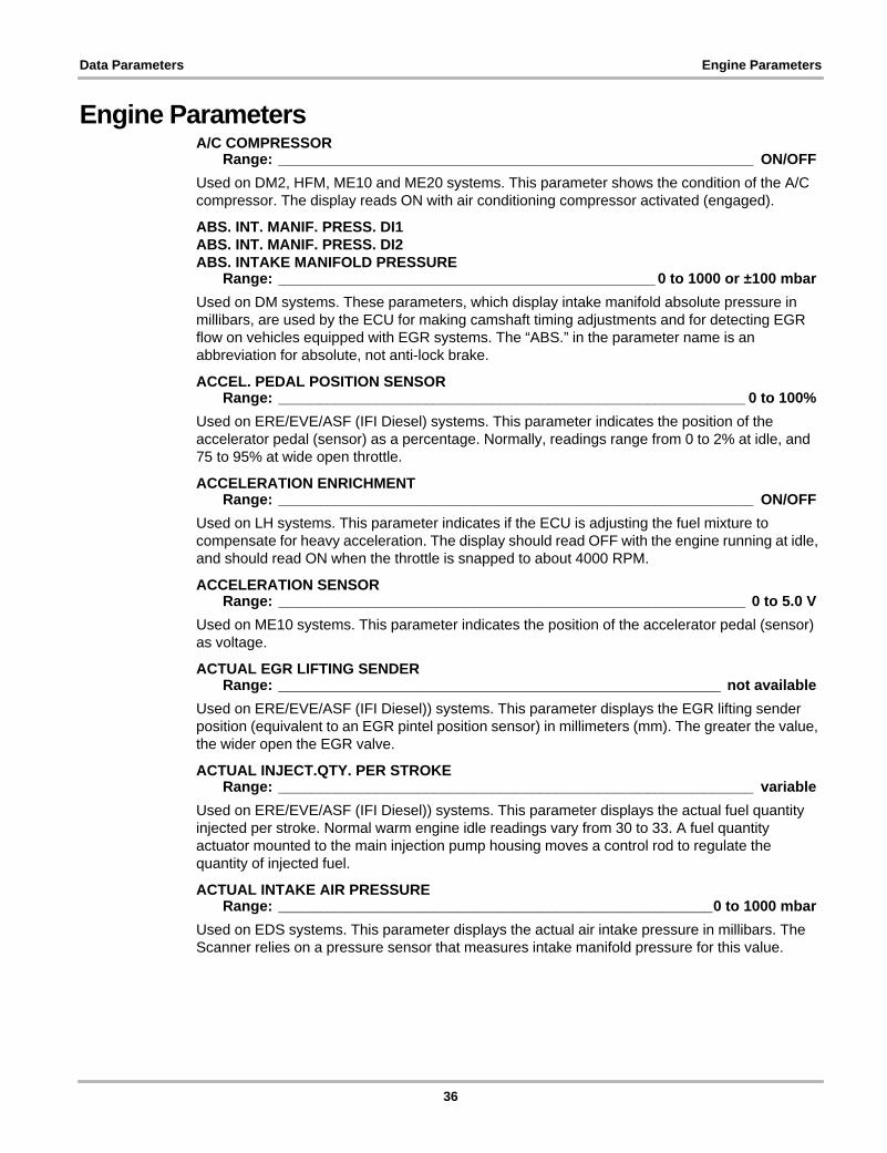
Data Parameters Engine Parameters
Engine ParametersA/C COMPRESSOR
Range: __________________________________________________________ ON/OFFUsed on DM2, HFM, ME10 and ME20 systems. This parameter shows the condition of the A/C compressor. The display reads ON with air conditioning compressor activated (engaged).
ABS. INT. MANIF. PRESS. DI1ABS. INT. MANIF. PRESS. DI2ABS. INTAKE MANIFOLD PRESSURE
Range: ______________________________________________ 0 to 1000 or ±100 mbarUsed on DM systems. These parameters, which display intake manifold absolute pressure in millibars, are used by the ECU for making camshaft timing adjustments and for detecting EGR flow on vehicles equipped with EGR systems. The “ABS.” in the parameter name is an abbreviation for absolute, not anti-lock brake.
ACCEL. PEDAL POSITION SENSORRange: _________________________________________________________ 0 to 100%
Used on ERE/EVE/ASF (IFI Diesel) systems. This parameter indicates the position of the accelerator pedal (sensor) as a percentage. Normally, readings range from 0 to 2% at idle, and 75 to 95% at wide open throttle.
ACCELERATION ENRICHMENTRange: __________________________________________________________ ON/OFF
Used on LH systems. This parameter indicates if the ECU is adjusting the fuel mixture to compensate for heavy acceleration. The display should read OFF with the engine running at idle, and should read ON when the throttle is snapped to about 4000 RPM.
ACCELERATION SENSORRange: _________________________________________________________ 0 to 5.0 V
Used on ME10 systems. This parameter indicates the position of the accelerator pedal (sensor) as voltage.
ACTUAL EGR LIFTING SENDERRange: ______________________________________________________ not available
Used on ERE/EVE/ASF (IFI Diesel)) systems. This parameter displays the EGR lifting sender position (equivalent to an EGR pintel position sensor) in millimeters (mm). The greater the value, the wider open the EGR valve.
ACTUAL INJECT.QTY. PER STROKERange: __________________________________________________________ variable
Used on ERE/EVE/ASF (IFI Diesel)) systems. This parameter displays the actual fuel quantity injected per stroke. Normal warm engine idle readings vary from 30 to 33. A fuel quantity actuator mounted to the main injection pump housing moves a control rod to regulate the quantity of injected fuel.
ACTUAL INTAKE AIR PRESSURERange: _____________________________________________________0 to 1000 mbar
Used on EDS systems. This parameter displays the actual air intake pressure in millibars. The Scanner relies on a pressure sensor that measures intake manifold pressure for this value.
36
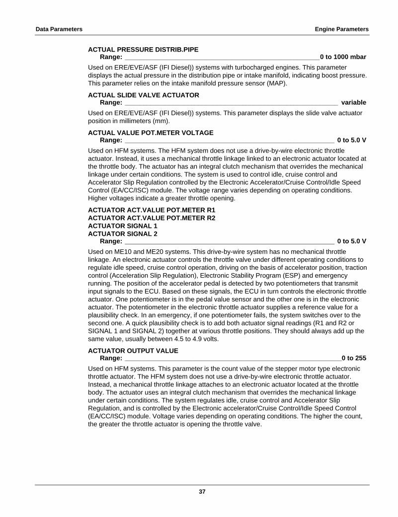
Data Parameters Engine Parameters
ACTUAL PRESSURE DISTRIB.PIPERange: _____________________________________________________0 to 1000 mbar
Used on ERE/EVE/ASF (IFI Diesel)) systems with turbocharged engines. This parameter displays the actual pressure in the distribution pipe or intake manifold, indicating boost pressure. This parameter relies on the intake manifold pressure sensor (MAP).
ACTUAL SLIDE VALVE ACTUATORRange: __________________________________________________________ variable
Used on ERE/EVE/ASF (IFI Diesel)) systems. This parameter displays the slide valve actuator position in millimeters (mm).
ACTUAL VALUE POT.METER VOLTAGERange: _________________________________________________________ 0 to 5.0 V
Used on HFM systems. The HFM system does not use a drive-by-wire electronic throttle actuator. Instead, it uses a mechanical throttle linkage linked to an electronic actuator located at the throttle body. The actuator has an integral clutch mechanism that overrides the mechanical linkage under certain conditions. The system is used to control idle, cruise control and Accelerator Slip Regulation controlled by the Electronic Accelerator/Cruise Control/Idle Speed Control (EA/CC/ISC) module. The voltage range varies depending on operating conditions. Higher voltages indicate a greater throttle opening.
ACTUATOR ACT.VALUE POT.METER R1ACTUATOR ACT.VALUE POT.METER R2ACTUATOR SIGNAL 1ACTUATOR SIGNAL 2
Range: _________________________________________________________ 0 to 5.0 VUsed on ME10 and ME20 systems. This drive-by-wire system has no mechanical throttle linkage. An electronic actuator controls the throttle valve under different operating conditions to regulate idle speed, cruise control operation, driving on the basis of accelerator position, traction control (Acceleration Slip Regulation), Electronic Stability Program (ESP) and emergency running. The position of the accelerator pedal is detected by two potentiometers that transmit input signals to the ECU. Based on these signals, the ECU in turn controls the electronic throttle actuator. One potentiometer is in the pedal value sensor and the other one is in the electronic actuator. The potentiometer in the electronic throttle actuator supplies a reference value for a plausibility check. In an emergency, if one potentiometer fails, the system switches over to the second one. A quick plausibility check is to add both actuator signal readings (R1 and R2 or SIGNAL 1 and SIGNAL 2) together at various throttle positions. They should always add up the same value, usually between 4.5 to 4.9 volts.
ACTUATOR OUTPUT VALUERange: ___________________________________________________________0 to 255
Used on HFM systems. This parameter is the count value of the stepper motor type electronic throttle actuator. The HFM system does not use a drive-by-wire electronic throttle actuator. Instead, a mechanical throttle linkage attaches to an electronic actuator located at the throttle body. The actuator uses an integral clutch mechanism that overrides the mechanical linkage under certain conditions. The system regulates idle, cruise control and Accelerator Slip Regulation, and is controlled by the Electronic accelerator/Cruise Control/Idle Speed Control (EA/CC/ISC) module. Voltage varies depending on operating conditions. The higher the count, the greater the throttle actuator is opening the throttle valve.
37

Data Parameters Engine Parameters
ADAPT. RANGE 2 GEAR, 6000-3000ADAPT. RANGE 2 GEAR, 6000-4000ADAPT. RANGE 4 GEAR, 2500-1500ADAPTED RANGES L1ADAPTED RANGES L2ADAPTED RANGES L3
Range: __________________________________________________________ ON/OFFUsed on ME20 systems. These parameters indicate whether the engine and transmission control modules are working together to optimize engine speed and torque for any one given driving condition.
ADJUST. CAMSHAFT TIMING SOLENOIDRange: __________________________________________________________ ON/OFF
Used on ME10 and ME20 systems. Camshaft timing is adjustable and this discrete parameter indicates the state of the camshaft timing solenoid. When the display reads ON, the solenoid is energized and when the display reads OFF it is not. Engine speed influences when the display reads ON or OFF. OFF indicates full retard position, and ON, full advance. The solenoid should be OFF at speeds below 2000 RPM, ON at speeds between 2000 RPM and 4300 RPM, and OFF at speeds over 4300 RPM.
ADR ACTIVERange: __________________________________________________________ ON/OFF
Used on ERE/EVE/ASF (IFI Diesel)) systems. This parameter indicates whether the ADR system is active or not. No further information is available.
ADR RPM ADJUSTMENTRange: __________________________________________________________ ON/OFF
Used on ERE/EVE/ASF (IFI Diesel)) systems. This parameter indicates whether the ADR RPM adjustment is on or off. No further information is available.
AFTER-START ENRICHMENTRange: __________________________________________________________ ON/OFF
Used on HFM. LH, ME10, ME20, ME27, ME28 and SIM4 systems. This parameter indicates if the ECU is providing a rich fuel mixture after a cold start. The display reads ON with fuel enrichment at cold start, then switches to OFF once the engine warms up.
AIR CONDITIONINGRange: __________________________________________________________ ON/OFF
Used on ME27, ME28 and SIM4 systems. This parameter indicates whether the ECU is commanding the air conditioning system is on or off.
AIR FLAPRange: _________________________________________________________ 0 to 100%
Used on ME20 systems. This parameter indicates the opening of the air flap as a percentage. At 0% the air flap is fully open, and at 100% is completely closed. The air flap controls supercharger boost based on air flap position, which is ECU pulse-width modulated. At 100% the air flap is closed; at 11 to 99% boost control is in part load range; and at 10% or less the air flap is open.
AIR FLAP SWITCHOVER ANGLERange: __________________________________________________________ 0 to 120°
Used on HFM systems. This parameter indicates the opening of the air flap in degrees. The ECU uses this signal to regulate supercharger boost. When the supercharger is providing boost, the reading should be greater than 85°.
38

Data Parameters Engine Parameters
AIR LOGIC CHAINRange: __________________________________________________________ YES/NO
Used on DM2 systems. This parameter indicates whether the onboard diagnostic secondary air system tests have run (YES) or not run (NO).
AIR MASSRange: ________________________________________ 0 to 500 kg/h or 0 to 500 mg/S
Used on DM2, EDS, ERE/EVE/ASF (IFI Diesel)), HFM, ME10, ME20 and SIM4 systems. The ECU generates this parameter based on the input signal from the mass airflow sensor. The reading indicates the mass of the intake air charge in kilograms per hour (kg/h), or milligrams per stroke (mg/S). Values on a warmed-up vehicle vary by system and by engine.
AIR PUMPRange: _________________________________________________ YES/NO or ON/OFF
Used on DM, DM2, HFM, LH, ME10 and ME20 systems. This parameter indicates the state of the secondary air pump. The display reads YES or ON when the pump is activated, and reads NO or OFF when the pump is off. Secondary air is pumped into exhaust system to reduce emissions under certain operating conditions. On HFM systems the pump should be on (YES) when engine temperature is below 40°F (4°C).
AIR PUMP ACTIVATIONRange: __________________________________________________________ YES/NO
Used on DM2 systems. This parameter indicates whether the ECU has commanded the air pump to activate.
AIR PUMP SWITCHOVER VALVEAIR PUMP SWITCHOVER VALVE, LEFTAIR PUMP SWITCHOVER VALVE, RIGHT
Range: ____________________________________________________ OPEN/CLOSEDUsed on ME27, ME28 and SIM4 systems. These discrete parameters indicate whether the air pump switch-over solenoid valves are open or closed. At cold start and during warm-up, solenoid valve should be in OPEN or up position, which directs air pump flow into the exhaust manifold to help reduce emissions. With the engine fully warmed up, the solenoid valve should read CLOSED, shutting or closing the air pump chamber to the exhaust manifold.
The SIM4 system does not have an air pump, but instead uses the supercharger as an air-pump during warm-up. The Recirculating Air Flap actuator is used to direct air into exhaust manifold and also is used to generate an Air Pump Switchover Valve position status.
Table 5-1 Typical idle readings
System Engine Typical Idle Reading
HFM
4-cylinder 8–15 kg/h6-cylinder 13–22 kg/h8-cylinder 15–25 kg/h12-cylinder 12–22 kg/h
ME10 & ME20
4-cylinder 8–15 kg/h6-cylinder 10–20 kg/h8-cylinder 12–25 kg/h12-cylinder 10–20 kg/h
SIM4 — 10–20 kg/h
39

Data Parameters Engine Parameters
BAROMETRIC PRESSUREALTITUDE PRESSURE
Range: ________________________________________________0 to 1000, ±100 mbarAMBIENT PRESSURE
Range: _____________________________________________________ 0 to 1000 kPa)Barometric Pressure is used on CD12, EAG, EDS, ERE/EVE/ASF (IFI Diesel)), EZ, LH, and HFM systems. Altitude Pressure and Ambient Pressure are used on SIM4 systems. The ECU calculates the barometric pressure based on the input signal from the barometric pressure (BARO) sensor. Readings display in millibar (mbar) or kilopascal (kPa). A typical reading at sea level is approximately 1000 mbar. Readings decrease as altitude increases.
ASR INTERVENTIONRange: __________________________________________________________ ON/OFF
Used on ME20 systems. This parameter indicates the operating state of the acceleration slip regulation (ASR), or traction control, system. The display reads ON when ASR is activated and OFF when it is inactive.
BASIC INJECTION DURATIONRange: ________________________________________________________ 0 to 30 ms
Used on LH systems. This parameter displays the length of time in milliseconds (ms) that the ECU commands the fuel injectors to remain on. Normal range is approximately 3 to 5 ms at idle.
BATTERY VOLTAGERange: __________________________________________________________ 0 to 25 V
Used on ARA/ELR, EDS, ERE/EVE/ASF (IFI Diesel)), EZ, LH, HFM, ME10, ME20, ME27, ME28, and SIM4 systems. This parameter represents the supply voltage provided by the charging system through the battery. Although the measurement range is 0 to 25 V, actual readings should be close to normal regulated charging system voltage with the engine running, typically 12.0 to 15.5 volts.
BOOST PRESSURERange: ______________________________________________________ 0 to 1000 kPa
Used on SIM4 systems. This parameter displays the boost pressure. The measurement units can be changed from kilopascal (kPa) to pounds per square inch (psi).
BOOST PRESSURE CONTROLRange: __________________________________________________________ ON/OFF
Used on ERE/EVE/ASF (IFI Diesel)) systems. This parameter indicates whether the boost pressure control is on or off. The boost pressure is controlled by the Inline Fuel Injection (IFI) control module. Boost is increased (closing the waste gate) when the boost pressure control valve is closed by the boost pressure control vacuum transducer through the vacuum unit. The boost pressure transducer is actuated by the control module with variable current and regulates the boost pressure vacuum unit.
BRAKE LAMP SWITCH VIA CANRange: __________________________________________________________ ON/OFF
Used on ERE/EVE/ASF (IFI Diesel)) systems. This parameter indicates whether the parking brake lamp switch (via the controller area network (CAN) bus) is on or off.
The CAN is a broadcast type of bus. This means that all modules “hear” all transmissions. There is no way to send a message to just a specific module; all modules invariably pick up all traffic. However, CAN hardware provides local filtering so each module reacts only to data whose identifiers are stored in its acceptance list. This very high frequency transmission requires a “twisted pair” of wires to address electromagnetic interference (EMI) concerns. Two wires also
40

Data Parameters Engine Parameters
ensure communication if one wire is damaged and provide the ability to recognize a CAN circuit fault. The two lines must not be interchanged as each represents either high or low level.
BRAKE SWITCHRange: __________________________________________________________ ON/OFF
Used on ME10 systems. This parameter is an ECU input that indicates brake pedal position. The display should read ON with the brake pedal depressed and OFF at all other times.
CAMSHAFT HALL-EFFECT SENSORRange: __________________________________________________________ variable
Used on ME10, ME20, ME27 and ME28 systems. This parameter indicates the state of the signal from camshaft position (CMP) sensor. On ME10 and ME 20, the reading switches between “55” and “AA,” depending on whether the Hall-effect signal is high or low. The value should by constantly switching whenever the engine is running, and the frequency of the switching increases and decreases in proportion to engine speed. Be aware, readings may be outside the normal range when the engine is cranking.
On ME27 and ME 28 systems, the parameter should read “Running” when the engine is running and “Not Running” when the engine is not running.
CAMSHAFT ADJUSTMENTCAMSHAFT CONTROLCAMSHAFT SOLENOIDCAMSHAFT TIMING
Range: __________________________________________________________ ON/OFFUsed on DM, DM2, LH, HFM and SIM4 systems. These parameters display the ECU signals to the variable camshaft timing solenoid. When ON, the ECU is energizing the solenoid to advance camshaft timing. Typically on 119 and 120 engines, the display reads OFF at idle and switches to ON at 2000 RPM. For all other engines, the display waits until 4000 RPM before switching to ON.
CAMSHAFT ADJUSTMENT VALVE, RIGHTCAMSHAFT ADJUSTMENT VALVE, LEFT
Range: __________________________________________________________ ON/OFFUsed on ME27 and ME28 systems. This parameter indicates whether the variable camshaft timing solenoid is on or off. Below 1500 RPM, the camshaft timing solenoid is OFF or de-energized—cam timing is retarded to reduce valve overlap which reduces residual exhaust gas. Between 1500 and 4000 RPM the camshaft timing solenoid is ON or energized. Cam timing is advanced to reduce mixture loss and improve performance. Above 4000 RPM, the camshaft timing solenoid is OFF or de-energized. Cam timing is retarded to improve cylinder re-charge.
CAMSHAFT CONTROL LOGIC CHAINRange: __________________________________________________________ YES/NO
Used on DM2 systems. This parameter indicates whether the onboard self diagnostic tests have run for the variable camshaft control system.
CAMSHAFT REFERENCE MARK SIGNALRange: __________________________________________________________ YES/NO
Used on DM2 systems. This parameter indicates whether the camshaft reference mark signal is on (YES) or off (NO). The Scanner normally displays NO with the key on, engine off, and when a camshaft position sensor fault exists.
41

Data Parameters Engine Parameters
CAMSHAFT SIGNAL, RIGHT BANKCAMSHAFT SIGNAL, LEFT BANK
Range: __________________________________________________________ YES/NOUsed on ME27 and ME28 systems. These parameters indicate whether there are camshaft signals from the left and right engine banks.
CAMSHAFT SOLENOIDRange: __________________________________________________________ ON/OFF
Used on HFM systems. This parameter indicates whether the camshaft solenoid is on or off.
CAN DATA EXCHANGERange: __________________________________________________________ YES/NO
Used on DM and DM2 systems. This parameter indicates whether the controller area network (CAN) bus data exchange signal is active or not active.
The CAN is a broadcast type of bus. This means that all modules “hear” all transmissions. There is no way to send a message to just a specific module; all modules invariably pick up all traffic. However, CAN hardware provides local filtering so each module reacts only to data whose identifiers are stored in its acceptance list. This very high frequency transmission requires a “twisted pair” of wires to address electromagnetic interference (EMI) concerns. Two wires also ensure communication if one wire is damaged and provide the ability to recognize a CAN circuit fault. The two lines must not be interchanged as each represents either high or low level.
CAN RECEPTION FROM ASRRange: _______________________________________________________ OK/NOT OK
Used on EZ systems. This parameter indicates if the controller area network (CAN) is receiving data from the acceleration slip regulation (ASR) module. The CAN is a serial data transmission bus and the ASR is the traction control system. The display should read OK at all times. The ASR system is disabled if the display reads NOT OK.
CAN RECEPTION FROM DASRange: _______________________________________________________ OK/NOT OK
Used on ERE/EVE/ASF (IFI Diesel)) systems. This parameter indicates whether the controller area network (CAN) is receiving data from the DAS module. The display should read OK at all times. A NOT OK reading indicates a loss of communication between the ECU and DAS module.
CAN RECEPTION FROM DI1CAN RECEPTION FROM DI2
Range: _______________________________________________________ OK/NOT OKUsed on EZ and LH systems. These parameters indicate whether the controller area network (CAN) is receiving data from distributor ignition modules 1 or 2 (DI1 or DI2). The display should read OK at all times. A reading of NOT OK indicates a loss of communication between the ECU and DI1 or DI2, which prevents ECU control of ignition.
CAN RECEPTION FROM EA,CC,ISCRange: _______________________________________________________ OK/NOT OK
Used on EZ and LH systems. This parameter indicates whether the controller area network (CAN) is receiving data from the electronic accelerator (EA), cruise control (CC) and idle speed control (ISC) modules. The display should read OK at all times. A reading of NOT OK indicates a loss of communication between the modules. When the display reads NOT OK, the electronic accelerator, cruise control and idle speed control functions are disabled and default values are being substituted.
42

Data Parameters Engine Parameters
CAN RECEPTION FROM LH1-SFICAN RECEPTION FROM LH2-SFI
Range: _______________________________________________________ OK/NOT OKUsed on EZ and LH systems. These parameters indicate whether the controller area network (CAN) is receiving data from the fuel injection (LH 1-SFI or LH2-SFI) modules. The display should read OK at all times. A NOT OK indicates a loss of communication between the modules.
CAN TRANSMISSION FROM DI1CAN TRANSMISSION FROM DI2
Range: _______________________________________________________ OK/NOT OKUsed on EZ systems. These parameters indicate whether the controller area network (CAN) is receiving a status transmission from the distributor ignition (DI1 and DI2) modules. The display should read OK at all times. A NOT OK means the ignition module is not responding to the ECU.
CAN TRANSMISSION FROM LH1-SFICAN TRANSMISSION FROM LH2-SFI
Range: _______________________________________________________ OK/NOT OKUsed on LH systems. These parameters indicate whether the controller area network (CAN) is receiving communication from the fuel injection (LH 1-SFI or LH 2-SFI) modules. The display should read OK at all times. A NOT OK indicates a loss of communication between modules.
The CAN is a broadcast type of bus. This means that all modules “hear” all transmissions. There is no way to send a message to just a specific module; all modules invariably pick up all traffic. However, CAN hardware provides local filtering so each module reacts only to data whose identifiers are stored in its acceptance list. This very high frequency transmission requires a “twisted pair” of wires to address electromagnetic interference (EMI) concerns. Two wires also ensure communication if one wire is damaged and provide the ability to recognize a CAN circuit fault. The two lines must not be interchanged as each represents either high or low level.
CANISTER PURGE DUTY CYCLECANISTER PURGE VALVE DUTY CYCLE
Range: _________________________________________________________ 0 to 100%Used on LH and SIM4 systems. This parameter indicates the duty cycle of the ECU-controlled canister purge solenoid. The pulse width modulated solenoid is energized to activate purging and switched off to prevent purging. A reading of 0% indicates purging is being prevented and a reading of 100% indicates the solenoid is fully energized for maximum purging. When purge is activated, duty cycle should gradually increase. This prevents rapidly dumping vapors into the intake charge, which would momentarily create an overly rich mixture.
CATALYST SELECTEDRange: __________________________________________________________ YES/NO
Used on EZ systems. This parameter indicates whether the system configuration is designed to operate with or without a catalytic converter. On U.S. models, the Scanner should display YES.
CATALYTIC CONVERTER HEATERRange: __________________________________________________________ ON/OFF
Used on ME27 and ME28 systems. This parameter indicates whether the catalytic converter heater is on or off.
CHARCOAL CANISTERRange: __________________________________________________________ ON/OFF
Used on ME20 systems. This parameter shows the ECU control status for charcoal canister purging. Purging is active when ON is displayed and prevented when OFF is displayed.
43

Data Parameters Engine Parameters
CHECK ENGINE AFTER FULFILLING FAULT SEQUENCERange: __________________________________________________________ YES/NO
Used on ME10 systems. This parameter indicates the check engine light status after an ECU diagnostic self-test. A reading of YES indicates a fault was detected during the self-test and the check engine light should be illuminated. A reading of NO indicates that no faults were present during the self-test.
CIRCUIT 15CIRCUIT 50
Range: __________________________________________________________ ON/OFFUsed on ERE/EVE/ASF (IFI Diesel)) and LH systems. This parameter indicates the state of circuit 15 or 50, which is the starter circuit. The display should read ON when the starter is engaged during cranking and OFF after engine starts.
CIRCUIT 50 OUTPUTCIRCUIT 50 INPUT
Range: __________________________________________________________ ON/OFFUsed on ERE/EVE/ASF (IFI Diesel)) systems. These parameters indicate the input or output state (on or off) of circuit 50, which is the starter circuit. When the starter cranks, both parameters should display ON.
CLUTCH DEPRESSEDRange: __________________________________________________________ ON/OFF
Used on HFM systems. This parameter indicates the state of the clutch switch input to the ECU. The display should read ON whenever the clutch pedal is depressed, and read OFF when the clutch pedal is not depressed.
CLUTCH SWITCHRange: __________________________________________________________ ON/OFF
Used on ERE/EVE/ASF (IFI Diesel)) and SIM4 systems. This parameter indicates whether the clutch switch is in the ON or OFF position. ON means the clutch is being depressed.
COIL FAULT COUNTER T1/1 CYL. 1/4COIL FAULT COUNTER T1/1 CYL. 2/5COIL FAULT COUNTER T1/2 CYL. 2/3COIL FAULT COUNTER T1/2 CYL. 3/4COIL FAULT COUNTER T1/3 CYL. 1/6
Range: ___________________________________________________________0 to 255Used on HFM distributorless systems. These parameters are numerical fault counters for the ignition coils. This is an ECU input used for monitoring coil output.
The abbreviations “T1/1,” “T1/2,” and “T1/3” refer to the three ignition coils; the numbers that follow, “1/4,” “2/5,” “2/3,” “3/4,” “1/6” refer to the cylinders the coils fire.
When the engine operates normally, the parameter values should be 0 or near 0. The greater the number, the more severe the misfire. Once a misfire causes the counter to reach 255, the ECU resets the parameter to 0. These parameters assist in troubleshooting misfires by pinpointing the problem to at least one of two cylinders.
44

Data Parameters Engine Parameters
COIL SPARK DURAT. T1/1 CYL. 1/4COIL SPARK DURAT. T1/1 CYL. 2/5COIL SPARK DURAT. T1/2 CYL. 2/3COIL SPARK DURAT. T1/2 CYL. 3/4COIL SPARK DURAT. T1/3 CYL. 1/6
Range: _________________________________________________________ 0 to 5 msUsed on HFM systems. These parameters represents the spark line duration, or burn time, in milliseconds (ms) from the ignition coils.
The abbreviations “T1/1,” “T1/2,” and “T1/3” refer to the three ignition coils; the numbers that follow, “1/4,” “2/5,” “2/3,” “3/4,” “1/6” refer to the cylinders the coils fire.
With the engine running at idle, readings between 0.8 and 1.5 ms are normal for 111 engines. At idle, readings between 1.5 and 1.9 ms are normal for all other engines.
COIL SPARK VOLTAGE T1/1 CYL. 1/4COIL SPARK VOLTAGE T1/1 CYL. 2/5COIL SPARK VOLTAGE T1/2 CYL. 2/3COIL SPARK VOLTAGE T1/2 CYL. 3/4COIL SPARK VOLTAGE T1/3 CYL. 1/6
Range: _________________________________________________________ 0 to 500 VUsed on HFM systems. These parameters represents the primary coil spark line, or burn time, voltage from the ignition coils.
The abbreviations “T1/1,” “T1/2,” and “T1/3” refer to the three ignition coils; the numbers that follow, “1/4,” “2/5,” “2/3,” “3/4,” and “1/6” refer to the cylinders that the coils fire.
Normal range for most engines running at idle is from 34 to 37 V. With a 111 engine running at idle the normal range is from 38 to 42 volts.
COMBUSTION TIME CYL. 1COMBUSTION TIME CYL. 2COMBUSTION TIME CYL. 3COMBUSTION TIME CYL. 4COMBUSTION TIME CYL. 5COMBUSTION TIME CYL. 6COMBUSTION TIME CYL. 7COMBUSTION TIME CYL. 8
Range: _________________________________________________________ 0 to 5 msUsed on EZ systems. This parameter represents the spark line duration, or burn time, in milliseconds for each cylinder. Normal range for an engine running at idle is 1.5 to 1.9 milliseconds (ms).
COMPRESSOR CLUTCHRange: __________________________________________________________ ON/OFF
Used on HFM and ME20 systems. This parameter shows the condition of the A/C compressor clutch. The display reads ON with air conditioning compressor clutch engaged and OFF when the clutch is disengaged.
COMPRESSOR EFFICIENCY FACTORRange: __________________________________________________________ variable
Used on HFM systems. This parameter is an ECU-calculated factor of supercharger efficiency. The display should read greater than 1.3 when driving in third gear at 3500 RPM under full load.
45

Data Parameters Engine Parameters
COOLING FAN OUTPUT DEMAND ENGINERange: __________________________________________________________ ON/OFF
COOL.FAN OUTP.DEMANDED BY ENGINERange: _________________________________________________________ 0 to 100%
Used on HFM and ME20 systems. This parameter indicates whether or not the ECU is commanding the cooling fan to turn on based on engine temperature. The display reads ON or 100% when the ECU is enabling the fan, and OFF or 0% when the ECU disables the fan.
COOL.FAN OUTP.DEMAND CLIMATE CTRLCOOL.FAN OUTP.DEMAND.BY CLIM.CTRL
Range: __________________________________________________________ ON/OFFUsed on HFM and ME20 systems. This parameter indicates whether or not the ECU is commanding the cooling fan to turn on based on the climate control system engaging the A/C compressor. The display reads ON when the ECU is enabling the fan and the compressor is engaged. Reads OFF when the fan is switched off and the compressor is disengaged.
COOLANT TEMPERATURERange: _________________________________________ –40 to 199°C or –40 to 390°F
Used on SIM4 systems. This parameter monitors engine coolant temperature. The measurement units can be changed from degrees Celsius (°C) to degrees Fahrenheit (°F).
CORRECTED INT.MANIFOLD PRESSRange: _____________________________________________________0 to 1000 mbar
Used on EAG systems. This parameter, which displays the corrected manifold absolute pressure reading in millibars (mbar), is used by the ECU for making camshaft timing adjustments. On vehicles equipped with EGR, the ECU also uses this parameter to detect EGR flow.
CR. CTRL SHUT-OFF BRAKES APPLIEDRange: __________________________________________________________ ON/OFF
Used on HFM systems. This parameter represents the signal from the brake switch to override and disengage cruise control. With the cruise control engaged, the display should read OFF while driving and ON whenever the brake pedal is depressed. When the display reads ON, the brake pedal is depressed, and cruise control operation should be suspended.
CRANKSHAFT MAGNET CODINGCRANKSHAFT SEGMENT ORDER
Range: __________________________________________________________ YES/NOUsed on DM2 systems. These parameters indicate whether the crankshaft position sensor ECU inputs are working correctly. The self diagnostic tests the crankshaft position sensor for adequate voltage output and for proper crankshaft gear timing signature.
CRUISE CONTROLCRUISE CONTROL ENGAGED
Range: __________________________________________________________ ON/OFFUsed on ME10, ME20 ME27, ME28 and HFM systems. These parameters represent the status of the cruise control system. The display reads ON when cruise control is engaged and OFF when disengaged.
46

Data Parameters Engine Parameters
CRUISE CONTROL LEVER POSITION VARIABLECRUISE CONTROL LEVER SIGNAL IMPLAUSIBLECRUISE CONTROL OFFCRUISE CONTROL RESTARTCRUISE CONTROL SET AND ACCELERATECRUISE CONTROL SET AND DECELERATE
Range: __________________________________________________ACTIVE/INACTIVEUsed on SIM4 systems. These parameters represent the status of the cruise control system. The display reads ACTIVE when cruise control is running and INACTIVE when not running.
CRUISE CONTROL SHUT-OFF FUNCTIONRange: __________________________________________________________ ON/OFF
Used on ME10 and ME20 systems. This parameter represents the cruise control system status. Note the parameter is a shut-off function, so the display reads OFF when cruise control is engaged and ON when disengaged.
CRUISE CONTROL SHUT-OFF SAFETYRange: __________________________________________________________ YES/NO
Used on ME10 and ME20 systems. This parameter represents the status of the cruise control safety switch in the electronic accelerator actuator. The ECU connects to the safety switch in the electronic accelerator actuator. Normal operation sends a positive signal to ECU. If throttle opening is more than the position specified and cruise control is not engaged, the switch sends a ground signal to the ECU, which turns off fuel injection. Injection switches on once engine speed is below 1200 RPM.
CRUISE CONTROL/SPEED LIMITER INTERVENTRange: __________________________________________________________ ON/OFF
Used on ME10 systems. This parameter indicates if the ECU is disabling the cruise control system due to excessive engine speed. The display reads ON if the maximum engine speed limitation is reached and cruise control operation is suspended. The display should read OFF during normal cruise control operation.
CRUISE CONTROL SWITCHRange: __________________________________________________________ ON/OFF
CRUISE CONTROL SWITCH ACRUISE CONTROL SWITCH BCRUISE CONTROL SWITCH ACCELERATECRUISE CONTROL SWITCH DECELERATE
Range: __________________________________________________________ YES/NOUsed on ERE/EVE/ASF (IFI Diesel)) and HFM systems. This parameter indicates the status of the cruise control switch. ON or YES means that the switch is in the ON position.
CSO, IDLE F.TRIM CYL.1-3, RIGHTCSO, IDLE F.TRIM CYL.4-6, RIGHTCSO, IDLE F.TRIM CYL.7-9, LEFTCSO, IDLE F.TRIM CYL.10-12, LEFT
Range: _________________________________________________ –0.700 to 0.700 msUsed on ME27 systems. These parameters indicate the fine tuning long term fuel trim correction to the fuel injection pulse width in milliseconds (ms). Cylinder shutoff (CSO) mode is used on the V12 engines with separate bank fuel control. Information on CSO mode is limited, however field technicians believe that if correct cruise conditions are met, cylinder groups are shut down to conserve fuel. (See the description for CYLINDER SHUT-OFF 1.) In this mode, mixture adaptation is modified for the active cylinders, compensating for variations in air mass and pressure ratios. This number is learned by the ECU and used to correct small differences
47

Data Parameters Engine Parameters
between engines and engine wear. Each change in the Long Term Fuel Trim is equivalent to a change of the Short Term Fuel Trim over its entire range. When the Short Term Fuel Trim reaches its upper/lower limit, it resets back to the beginning, and moves Long Term Fuel Trim up or down by one count. The Short Term Fuel Trim continues to move very quickly and if the limits are reached, it will increment the Long Term Fuel Trim again. This will continue until either the fuel mixture problem is corrected or long term fuel reaches it limit, causing a DTC to set.
This fine tuning fuel trim correction is also called Additive Mixture Adaptation because it can modify the duration of injection by adding or subtracting to the base injection time in each fuel map cell. It thus affects the entire engine speed range or all fuel map cells, but is most noticeable at idle because of the minimal amount of adjustment capability.
CSO, LOW.P.LOAD F.TRIM CYL 1-3, RIGHTCSO, LOW.P.LOAD F.TRIM CYL 4-6, RIGHTCSO, LOW.P.LOAD F.TRIM CYL 7-9, LEFTCSO, LOW.P.LOAD F.TRIM CYL 10-12, LEFT
Range: ______________________________________________________0.750 to 1.280Used on ME27 systems. Cylinder shutoff (CSO) mode is used on the V12 engines with separate bank fuel control. Information on CSO mode is limited, however field technicians believe that if correct cruise conditions are met, cylinder groups are shut down to conserve fuel. (See the description for CYLINDER SHUT-OFF 1.) In this mode, mixture adaptation is modified for the active cylinders, compensating for variations in air mass and pressure ratios. These fuel trim numbers represent the long term correction to the injection system when the engine is under partial load and in CSO mode. This number is learned by the ECU and is used to correct small differences between engines and engine wear. When the short term correction (O2 Integrator) is outside the window defined in the ECU memory, the long term fuel trim (FTRIM) is changed. PART LOAD F.TRIM can modify injector duration using a self-adaptation factor. A 1.0 reading represents the base point. Readings greater than 1.0 indicate that the system is running lean and to correct—the injection duration is increased. Readings less than 1.0 indicate that the system is running rich and to correct—the injection duration is decreased.
These parameters display a long-term correction factor applied to the CSO programmed low partial load base cell values.
CTP (IDLE) ADJUSTMENT VALUERange: ______________________________________________________ not available
Used on ME10 and ME20 systems. No information is available at this time.
CTP (IDLE)CTP (IDLE) CONTACTCTP (IDLE) INFORMATIONCTP (IDLE) RECOGNITION
Range: _________________________________________________ YES/NO or ON/OFFUsed on DM, DM2, ERE/EVE/ASF (IFI Diesel)), HFM, LH, ME10 and ME20 systems. These parameters indicate the state of the throttle switch. The display should read YES or ON when the throttle is closed and NO or OFF when the throttle is open.
CTP (IDLE) LONG-TERM ADAPT. VALUESRange: ______________________________________________________ not available
Used on ME10 and ME20 systems. No further information is available at this time.
CYL. 1 to 12Range: __________________________________________________________ ON/OFF
Used on LH, ME10, ME20, systems. These parameters indicate whether or not fuel injector operation has been suspended to reduce fuel consumption during cruise. The “1 to 12" in the
48

Data Parameters Engine Parameters
parameter name indicates twelve separate parameters, one for each cylinder. The display reads OFF when fuel injection is suspended and ON during normal fuel injection operation.
CYLINDER SHUT-OFF 1 to 12CYLINDER SHUT-OFF VALVE, RIGHTCYLINDER SHUT-OFF VALVE, LEFT
Range: __________________________________________________________ ON/OFFUsed on ME27 (V12) and ME28 systems. These parameters indicate whether or not cylinder operation has been suspended to reduce fuel consumption during certain cruise conditions. The “1 to 12" in some of the parameter names indicate up to twelve separate parameters, one for each cylinder. The display reads OFF when a cylinder or engine bank has been shut down. It reads ON if that cylinder or bank is in normal operation. For those cylinders or bank shut-off, fuel injection is eliminated and ignition spark is drastically reduced. For the ME27 V12 engine, cylinder shutoff may disable up to 6 cylinders, usually all on the left engine bank (cylinders 7-12), depending on engine load requirements. Cylinder shutoff starts with the number 7 cylinder or the number 12 cylinder. Exhaust valves are shut off first, followed by the intake valves. This maintains exhaust gas pressure in the cylinder, preventing crankcase oil from being drawn up due to vacuum. Oil pressure is used to operate coupling valve levers which can engage or disengage rocker arms. In the disengaged mode, valves do not open and remain permanently closed during cylinder shutoff operation.
On ME28 engines, complete left or right engine bank is disabled using ME-controlled solenoids that disable all the valves on one bank simultaneously.
DAS AND DSV MODULES ARE MATCHEDDAS AND ECM COMPATIBLEDAS AND ENGINE CTRL. MOD. COMPATIBLE
Range: __________________________________________________________ YES/NODAS CONTROL MODULES
Range: _______________________________________________________ OK/NOT OKUsed on ERE/EVE/ASF (IFI Diesel)), ME10 and ME20 systems. These parameters show if the drive authorization system (DAS) or anti-theft system and the ECU have correctly identified each other at startup. The display reads YES if the modules identify each other and NO if they do not. The ECU and DAS module are permanently interlocked, after a fixed number of starts when replacing the ECU, by an identification code that cannot be erased. Therefore, it is not possible to interchange modules from another vehicle for test purposes. Interchanges can only be done with a matched pair of modules. The ME-SFI module has an immobilizer. When the vehicle is locked, the DAS sends a signal to the ME-SFI that inhibits injection. Engine starting is prohibited unless the authorized key is used and a start enable signal from the DAS module is received by the ME-SFI module.
DECELERATIONRange: __________________________________________________________ YES/NO
DECELERATION SHUT-OFFRange: __________________________________________________________ ON/OFF
Used on DM2, EGS, HFM, LH, ME10 and ME20 systems. These parameters indicate whether the ECU has temporarily shut off fuel injection during deceleration to reduce emissions. The display reads ON or YES if the ECU commands the injectors off during deceleration, and reads OFF or NO at all other times.
Certain conditions must be met to activate: engine coolant temperature must be above 122°F (50°C), engine speed must be above 2100 RPM, and vehicle speed over 22 mph. The ECU recognizes deceleration when the throttle valve position is less than that required for a specific engine speed, or when the ECU senses closed throttle idle contacts. Once RPM drops to 1000, the injectors switch back on. The ignition timing is momentarily retarded to avoid a power surge.
49

Data Parameters Engine Parameters
DESIRED ENGINE SPEEDRange: _____________________________________________________ 0 to 1500 RPM
Used on HFM systems. This parameter indicates the target idle speed that the ECU is attempting to maintain. With a normal running engine, actual and desired engine speeds should be equal or close to each other.
DISTRIBUTOR SHAFT ACTUAL POS.DISTRIBUTOR SHAFT NOMINAL POS.
Range: _________________________________________________________ 0 to 100%No information is available at this time.
DRIVE AUTH. RCL & ECM COMPATIBLERange: __________________________________________________________ YES/NO
Used on HFM systems. This parameter indicates whether the remote controller locking (RCL) system and the ECU correctly identified each other. The display reads YES if the modules are properly coded. Coding cannot be erased, so swapping modules for testing cannot be done unless a matched pair is used.
DRIVE AUTHORIZ.,IMMOBOLIZERRange: _______________________________________________ ACTIVE/NOT ACTIVE
Used on ME27 and ME28 systems. This parameter indicates whether the driver immobilizer is active or not active. The driver immobilizer is that part of the antitheft system that allows the vehicle to be remotely disabled via satellite. Often this parameter may read ACTIVE with a faulty or wrong ignition key.
DRIVER GIVEN TORQUERange: ______________________________________________________ not available
Used on HFM systems. No information is available at this time.
DWELL TIME, CYLINDER 1 to 12Range: ______________________________________________________ not available
Used on ME27 and ME28 systems. This parameter displays the dwell timing (coil saturation time) for the various cylinder banks in seconds.
EBR INTERVENTIONRange: __________________________________________________________ ON/OFF
Used on ME10 systems. This parameter indicates the state of the engine brake regulation (EBR), or traction control, system. Display reads ON when EBR has been activated and OFF during normal driving.
ECM IDENTIFIEDENGINE CONTROL MODULE IDENTIFIED
Range: __________________________________________________________ YES/NOUsed on ERE/EVE/ASF (IFI Diesel)), ME10, ME20 and HFM systems. These parameters indicate whether the drive authorization system (DAS) and ECU have correctly identified each other. The display reads YES if the modules have correctly identified each other and will read NO if they have not correctly identified each other. The modules are coded together and the mutually shared code cannot be erased.
ECM LOCKEDENGINE CONTROL MODULE LOCKED
Range: __________________________________________________________ YES/NOUsed on ERE/EVE/ASF (IFI Diesel)), ME10, ME20 and HFM systems. These parameters show if the drive authorization system (DAS) and ECU have correctly identified each other. If the display reads YES, the modules have not identified each other and the engine is prevented from starting.
50

Data Parameters Engine Parameters
ECT LH1ENGINE COOLANT TEMP. 1ECT LH2ENGINE COOLANT TEMP. 2
Range: ________________________________________________________ 0 to 5.00 VUsed on DM and LH systems. These parameters display the voltage drop created by the resistance of the engine coolant temperature (ECT) sensors. The ECT is a negative temperature coefficient (NTC) sensor, so resistance decreases as temperature increases. The display should read high voltage on a cold startup, then gradually drop as the engine warms up. The ECU uses the ECT signal to regulate fuel injection for starting, after start enrichment, during warm-up enrichment, acceleration enrichment, deceleration fuel shutoff; ignition timing at startup, warm-up, closed throttle and deceleration shut-off; catalyst warm-up, charcoal canister purge, 2-3 upshift delay, camshaft adjustment, overheat protection and anti-knock control.
ECT OPERATING TEMPERATUREECT SENSORECT VALUE RANGE
Range: __________________________________________________________ YES/NOUsed on DM and DM2 systems. These parameters indicate that the ECU self diagnostic tests for the engine coolant sensors have run.
EFFECT.COOL.FAN OUTPUT DUTY CYCLERange: __________________________________________________________ 0 to 95%
Used on HFM systems. This parameter displays the effective output of the cooling fan. The display shows the duty cycle of the cooling fan, which is controlled by the ECU.
EGREGR ACTIVATIONEGR LOGIC CHAINEGR VALVE
Range: __________________________________________________________ ON/OFFUsed on DM, LH and ME20 systems. These parameters indicate the state of the exhaust gas recirculation (EGR) system. On LH systems, EGR is controlled by the LH module through the EGR switch-over valve. On ME20 systems the ECU processes engine speed, air mass and coolant temperature input signals to control EGR. The display reads ON when the ECU is commanding recirculation and OFF when EGR is off. Approximately 10 to 15% of the exhaust gas is recirculated. On LH systems, the ECU prevents EGR until the engine coolant temperature reaches 149°F (65 °C). On ME20 systems, engine coolant temperature must reach 118°F (48 °C), and the closed throttle position switch must be open to allow EGR.
EGR LOGIC CHAINRange: __________________________________________________________ ON/OFF
Used on DM2 systems. This parameter indicates that the ECU on-board diagnostic tests for the EGR system have run. Any problem would be reported as a diagnostic trouble code.
EGRRange: __________________________________________________________ ON/OFF
EGR VALVERange: _________________________________________________________ 0 to 100%
Used on ERE/EVE/ASF (IFI Diesel)). In systems without a turbocharger, the ECU controls the EGR vacuum transducer by applying a variable current. The EGR Valve parameter ia a calculated value based on the applied current. The greater the percentage, the larger the EGR valve opening.
51

Data Parameters Engine Parameters
Turbo systems rely on the ECU to vary current to the EGR switchover valve, which regulates vacuum to the EGR valve. The greater the control current, the greater the EGR flow.
ELECTRIC AIR PUMPRange: __________________________________________________________ ON/OFF
Used on ME27 and ME28 systems. This parameter indicates the state of the electric air pump, on or off. The air is forced into the exhaust manifold through the air pump switchover valve. These air injection systems only operate during cold and warm-up conditions.
ELECTRIC COOLING FANRange: __________________________________________________________ ON/OFF
Used on HFM and ME20 systems. This parameter indicates the state of the electric cooling fan. The ECU switches the fan ON when engine coolant temperature reaches a certain point.
ENGINE BRAKE TORQUERange: __________________________________________________________ variable
Used on HFM systems. This parameter is an ECU-calculated value that indicates engine torque as newton-meters (Nm). Engine load partially determines engine brake torque.
ENGINE COOLANT TEMPERATURE(V)Range: ________________________________________________________ 0 to 5.00 V
ENGINE COOLANT TEMPERATURE(°)Range: _________________________________________–40 to 255°C or –40 to 491 °F
Used on ARA/ELR, DM, DM2, EDS, ERE/EVE/ASF (IFI Diesel)), EZ, HFM, ME10, ME20, ME27, and ME28 systems. This parameter displays either the voltage drop created by the resistance of the engine coolant temperature (ECT) sensor, or the calculated temperature based on the voltage signal. The ECT is a negative temperature coefficient (NTC) sensor, so resistance decreases in proportion to temperature increases. The display should read high voltage on a cold startup, then gradually drop as the engine warms up. In most cases the engine coolant temperature will be displayed in °C. The measurement units can be changed from degrees Celsius (°C) to degrees Fahrenheit (°F).
ENGINE LOADRange: _________________________________________________________ 0 to 100%
Used on ME10, ME20, ME27, ME28, and SIM4 systems. This parameter is an ECU-calculated engine load displayed as a percentage. The ECU determines engine load based on RPM, number of cylinders, airflow, and cylinder air charge. Input sensor readings are compared to a theoretical air charge that occurs at standard ECU temperature and pressure (volumetric efficiency). The resulting ratio, called engine load, is expressed as a percentage. With the engine running at idle under a normal load readings should be between 20 to 40%. During normal driving, load should be lower than 80%.
The ME-MOTRONIC engine management system uses torque-led control, which means it calculates the internal torque produced during combustion. This is the physical force produced by gas pressure during the compression and power strokes. The actual net torque of the engine has to account for friction, gas transfer losses and drive power for ancillary equipment, such as the water pump, alternator and AC compressor. The ME program contains the optimal specifications for charge density, injection duration, and ignition timing for any desired torque, which makes it possible to obtain optimal emissions and fuel consumption for every operational mode. Operational demands are prioritized and coordinated individually to use the appropriate control to achieve the specified torque. Torque based control is possible because the electronic accelerator permits throttle valve control beyond the pedal value inputs.
52

Data Parameters Engine Parameters
ENGINE OIL LEVELRange: _______________________________________________________ OK/NOT OK
Used on ME10 systems. This parameter indicates whether there is or is not enough engine oil in the crankcase. Display should read OK at all times. The display only reads NOT OK if the engine oil falls below a certain level, which indicates the possibility of engine damage.
ENGINE OIL TEMPERATURERange: _________________________________________ –60 to 116°C or –76 to 240°F
Used on ME20 systems. This parameter is based on the input signal of the engine oil temperature sensor, and displays engine oil temperature. The measurement units can be changed from degrees Celsius (°C) to degrees Fahrenheit (°F).
ENGINE SPEEDRange: _______________________________________________ 0 to engine maximum
Used on all systems. This parameter is the engine crankshaft speed displayed as revolutions per minute (RPM). RPM is internally calculated by the ECU based on reference pulses from the ignition system or the crankshaft position (CKP) sensor.
ENGINE SPEED LIMITERENGINE START CONTROL
Range: __________________________________________________________ ON/OFFUsed on HFM, ME27 and ME28 systems. This parameter indicates whether the ECU is limiting engine speed. The display should read OFF under normal operating conditions. A reading of ON indicates the ECU is taking preventive measures to avoid internal damage. To protect the engine, torque converter and powertrain, the ECU limits engine speed under specific operating conditions by leaning the air-fuel mixture, cutting off fuel delivery, or retarding ignition timing.
ENGINE START TEMPERATURERange: ___________________________________________–6 to116°C or –21 to 240°F
Used on HFM, ME10, ME20 ME27, ME28 and SIM4 systems. This parameter displays what the engine coolant temperature was when the engine was started. The parameter resets with each key cycle, and shows engine start temperature. The measurement units can be changed from degrees Celsius (°C) to degrees Fahrenheit (°F).
ETS INTERVENTIONRange: __________________________________________________________ ON/OFF
ETSRange: __________________________________________________________ YES/NO
Used on HFM systems. These parameters indicates whether the electronic traction system engaged. The display reads ON or YES when the electronic traction system is engaged, and OFF or NO when disengaged.
ETS INTERVENTIONRange: __________________________________________________________ ON/OFF
Used on ME20, ME27 and ME28 systems. This parameter shows the state of the exhaust flap, which is positioned on one side of the exhaust system between the three-way catalyst (TWC) and the rear muffler. The display reads ON when the ECU is commanding the vacuum-operated valve to close, and OFF when the valve is open. The purpose of the flap is to increase back-pressure in the exhaust and to minimize noise during cruise conditions when fuel is shut-off on one bank of cylinders to conserve fuel. Typically, the exhaust flap closes (ON) at speeds up to approximately 2300 to 2500 RPM when cylinder shut off is ON. The flap does not completely seal off the exhaust pipe, but restricts it enough to dampen noise and to equalize temperature between banks.
53

Data Parameters Engine Parameters
EXHAUST GAS TEMPERATUREEXHAUST TEMPERATURE (TWC MODEL)
Range: ______________________________________________________ not availableUsed on HFM, LH, ME10, ME27 and ME28 systems. These parameters are the ECU calculated exhaust gas temperature based on multiple input signals, and shows exhaust gas temperature. The measurement units can be changed from degrees Celsius (°C) to degrees Fahrenheit (°F).
EXHAUST TEMPERATURE LEFTEXHAUST TEMPERATURE RIGHT
Range: ______________________________________________________ not availableUsed on ME10 systems. These parameters are ECU-calculated exhaust gas temperatures for the left and right cylinder banks based on multiple input signals, and shows exhaust temperature. The measurement units can be changed from degrees Celsius (°C) to degrees Fahrenheit (°F). The preset measurement is °C.
FAN CAPACITY REQUEST BY A/CFAN CAPACITY REQUEST BY ENGINEFAN CAPACITY, EFFECTIVE
Range: _________________________________________________________ 0 to 100%Used on ME27, ME28, and SIM4 systems. These parameters indicate the amount of the fan capacity used, as requested by the A/C system or the engine.
FRONT AXLE SPEEDRange: ___________________________________________________ 0 to vehicle max
Used on ME27 and ME28 systems. This parameter indicates the speed of the front axle based on input signals to the ECU from the wheel speed sensors. The measurement units can be changed from KPH to MPH.
FUEL CANISTER PRESSURE DIFF.Range: ____________________________________________ –50 to 30 HPA or 0 to 5 V
Used on ME27, ME28 and SIM4 systems. This parameter indicates fuel canister pressure difference. This pressure sensor is integral to the fuel level sender assembly. It detects pressure in the fuel evaporative system. Pressure varies with the pulsed actuation of the purge control valve. At sea level with the gas cap removed, normal voltage should be about 2.9 to 3.0 volts.
FUEL LEVELRange: _______________________________________________ 0 to full tank capacity
Used on SIM4 systems. This parameter displays the fuel level in liters.
FUEL PUMPRange: __________________________________________________________ ON/OFF
Used on LH systems. This parameter indicates the state of the fuel pump. The display reads ON when the fuel pump is energized and OFF when the pump is not running.
FUEL RACK TRAVELRange: __________________________________________________________ variable
Used on ERE/EVE/ASF (IFI Diesel)) diesel systems. The amount of travel is measured in millimeters. With the engine warm at idle, the normal travel range is 7.5 to 9.5 mm. Cold engine travel range is from 12 to 18 mm. With the engine fully warm, under load, fuel rack travel should read more than 12 mm. The fuel rack integral to the main fuel injection pump controls the fuel volume to the injectors, and works in conjunction with the fuel quantity actuator. The fuel rack position sensor measures the amount of travel of the fuel quantity actuator control rod.
54

Data Parameters Engine Parameters
FUEL RACK POSITIONRange: __________________________________________________________ variable
Used on EDS diesel systems. The display shows the fuel rack position in millimeters. With the accelerator not depressed, the display should read approximately 10 mm. The value should increase to about 20 mm at WOT as the accelerator pedal is slowly depressed.
FUEL TANK CAPRange: _______________________________________________________ OK/NOT OK
Used on ME10 systems. This parameter indicates whether the fuel tank cap is properly installed. The display reads OK if the cap is correctly installed. A reading of NOT OK indicates a cap not sealing, or a major evaporative emissions system leak.
FUEL TANK LEVELRange: _______________________________________________________ OK/NOT OK
Used on ME10 and ME20 systems. This parameter indicates whether there is the proper amount of fuel in the fuel tank to run an evaporative emissions (EVAP) test. The display reads OK if the fuel level is within test range, and NOT OK if the fuel level is outside the test range.
FUEL TEMPERATURERange: __________________________________________ –6 to 116°C or –21 to 240°F
Used on ERE_EVE_ASF (IFI Diesel). Fuel temperature is measured in order to calculate the fuel density. It is also used for a substitute signal in the event of a coolant temperature sensor failure. This parameter relies on the fuel temperature sensor, which is located in the electro-hydraulic fuel cut off valve on the main injection pump. The measurement units can be changed from degrees Celsius (°C) to degrees Fahrenheit (°F).
FULL LOAD DETECTIONRange: _________________________________________________ ON/OFF or YES/NO
Used on ME27, ME28 and SIM4 systems. This parameter reads YES or ON when the engine fuel management system is functioning in full load operating mode.
FUNCTION FAULTRange: __________________________________________________________ YES/NO
Used on HFM systems. This parameter indicates whether a functional problem exists with a specific component or system. The reading is YES if a fault is detected and NO if not.
HFM VOLTAGEHOT FILM VOLTAGEHOT WIRE VOLTAGEHOT FILM MASS AIR FLOW SENSOR
Range: ________________________________________________________ 0 to 5.00 VUsed on ME10, ME20, ME27, ME28, HFM and LH systems. These parameters show the voltage required to maintain a 320°F (160 °C) temperature in the heated circuit of the mass air flow sensor. Normal ranges vary between systems. On ME systems, expect to see 1.4 to 1.5 volts (10 to 20 kilograms per hour (kg/h)) with a hot engine running at idle and all accessories off and 2.0 and 2.2 volts at 3000 RPM. For HFM systems idle readings should be about 0.7 to 0.9 volts and readings at 3000 RPM about 1.7 to 1.9 volts. With a LH system, look for readings between 0.7 and 1.7 volts at idle. The hot film airflow sensor controls the temperature of the heating resistor (Rh) with a variable voltage. Temperature is maintained at 320°F (160 °C) above the intake air temperature detected by the temperature resistor (Rl). The sensor (Rs) monitors heating resistor (Rh) temperature. If the temperature changes, the ECU alters voltage applied to the heating resistor (Rh) until the correct temperature difference is again achieved.
55

Data Parameters Engine Parameters
HOT WIRE AIR MASSHOT FILM MASS AIR FLOW SENSOR
Range: ______________________________________________________ 0 to 500 kg/hThese parameters are an ECU calculation of the mass of the intake air charge in kilograms per hour (kg/h) based on the input of the hot film mass airflow sensor. Normal hot idle values vary depending on engine. In general, readings from 15 to 30 kg/h are normal for a hot engine running at idle with all accessories switched off.
HFM-SFI MAPRange: ______________________________________________________ not available
Used on HFM systems. No information is available at this time.
HOLD GEARRange: __________________________________________________________ ON/OFF
Used on ME10 and ME20 systems. This parameter is a cruise control input that indicates if the ECU is maintaining a transmission range during hill climbing or other high-load condition. Reads ON when a specific gear is being held, and OFF during normal driving conditions.
IDLE FUEL TRIM ADAPTATION LEFTIDLE FUEL TRIM ADAPTAT. RIGHT
Range: _________________________________________________________ –1 to 1msIDLE FUEL TRIM CYL. 1-3 RIGHTIDLE FUEL TRIM CYL. 4-6 RIGHTIDLE FUEL TRIM CYL. 7-9 LEFTIDLE FUEL TRIM CYL. 10-12 LEFT
Range: ______________________________________________________ –0.7 to 0.7msUsed on ME27 and ME28 systems. These fuel trim numbers represent the fine tuning long term correction to the fuel injection pulse width to either individual banks or groups of cylinders. This number is learned by the ECU and used to correct small differences between engines and engine wear. When the short term correction is outside the window defined in the ECU memory, the long term fuel trim is changed. Each change in the Long Term Fuel Trim is equivalent to a change of the Short Term Fuel Trim over its entire range. When the short-term Fuel Trim reaches its upper or lower limit, it resets back to the beginning, and moves the long term fuel trim up or down by one count. The short term fuel trim continues to move very quickly and if the limits are reached, it again will increment the long term fuel trim. This will continue until either the fuel mixture problem is corrected or long term fuel trim reaches its limit and a DTC sets.
This type of adaptation adjusts long term fuel trim in small, incremental amounts. It is also called Additive Mixture Adaptation because it can modify the duration of injection by adding or subtracting to the entire fuel map by a incrementally small amount, which affects all cells equally the same. It thus affects the entire engine speed range or all fuel map cells, but is most noticeable at idle because of the minimal amount of adjustment capability.
Additive Mixture adaptation addresses faults that are most severe at idle, and lessen in severity as engine speed increases. A vacuum leak would be a typical example. This type of adaptation is not dependent on base injection duration.
IDLE SPEED CONTROLIDLE SPEED DETECTIONIDLE SPEED RECOGNITION
Range: __________________________________________________________ YES/NOUsed on DM, ERE/EVE/ASF (IFI Diesel)), ME27, ME28, and SIM4 systems. These parameters indicate whether the idle speed control circuit is on or off.
56

Data Parameters Engine Parameters
IFI/DFI RECEIVING FROM ETC (722.6)Range: __________________________________________________________ ON/OFF
IFI/DFI RECEIVING FROM ETS/ABSIFI/DFI RECEIVING FROM ETS/ABS/ASRIFI/DFI RECEIVING MESSAGE 1 FROM ICIFI/DFI RECEIVING MESSAGE 2 FROM ICIFI/DFI TRANSM. TO ASR/ESP/ A/C /ETCIFI/DFI TRANSM. TO IC/ASR/ETC (722.6)IFI/DFI TRANSMITTING TO ETC/ASRIFI/DFI TRANSMITTING TO ETC/IC
Range: __________________________________________________________ YES/NOENGINE CONTROL MODULE OR CAN-BUS
Range: _______________________________________________________ OK/NOT OKUsed on ERE/EVE/ASF (IFI Diesel)) (IFI Diesel). These parameters indicate whether controller area network (CAN) data bus communications are properly received by individual control units. The total of the data blocks, the short pause between two transmission cycles, and other properties of the CAN data bus, are constantly checked. Any faults detected are stored.
IGNITION ADVANCE ANGLEIGNITION ANGLEIGNITION FIRING POINT CYLINDER 1
Range: __________________________________________________ –30 to 60 degreesUsed on DM2, EZ, HFM, ME10, ME20, ME27, ME2, and SIM4 systems. These parameters displays the ignition spark angle, or timing, in degrees. The display shows timing advance as a positive (+) value and retard as a negative (-) value. Timing advance changes with engine speed and load, varying model and engine. See the Vehicle Emissions Certification Identification (VECI) sticker for the ignition spark angle range at idle.
IGNITION FAULT COUNTER CYL. 1IGNITION FAULT COUNTER CYL. 2IGNITION FAULT COUNTER CYL. 3IGNITION FAULT COUNTER CYL. 4IGNITION FAULT COUNTER CYL. 5IGNITION FAULT COUNTER CYL. 6
Range: ___________________________________________________________0 to 255Used on HFM systems. These parameters display the number of OBD ignition misfire faults detected per cylinder.
IGNITION VOLTAGE CYL. 1 to 12Range: _________________________________________________________ 0 to 500 V
Used on EZ systems. The “1 to 12" in the parameter name represent twelve separate parameters, one for each cylinder. These parameters display the primary coil spark line, or burn time, voltage per cylinder. Normal range is 34 to 37 V on a hot engine running at idle.
IMMOBILIZER STATUSRange: __________________________________________________________ ON/OFF
Used on SIM4 systems. This parameter indicates whether the immobilizer (anti-theft system) circuit is on or off.
INDICATED ENGINE TORQUERange: ______________________________________________________ not available
Used on HFM, ME27 and ME28 systems. This parameter is ECU-calculated, displaying engine torque in Newton meters (Nm). The parameter value varies according to engine load.
57

Data Parameters Engine Parameters
INERTIA FUEL SHUTOFFRange: _________________________________________________ ON/OFF or YES/NO
Used on ME27 and ME28 systems. This parameter indicates if the ECU has temporarily shut off fuel injection during deceleration to reduce emissions. The display reads ON or YES if the ECU commands the injectors off during deceleration, and reads OFF or NO at all other times. Certain conditions must be met to activate: engine coolant temperature must be above 122 °F (50 °C), engine speed above 2100 RPM, and vehicle speed over 22 mph. The ECU recognizes deceleration when the throttle valve position is less than that required for a specific engine speed, or when the throttle idle contacts are closed. Once RPM drops to 1000, the injectors switch back on and the ignition timing is momentarily retarded to avoid a surge in power.
INJECTION DURATION CORRECTIONRange: _________________________________________________________ 0 to 100%
Used on LH systems. This parameter displays the additional time that the ECU is commanding the fuel injectors on to compensate for natural flow rate inconsistencies. As injectors open and close they induce pressure waves in the fuel lines that cause flow rate inconsistencies. An adaptation factor correlated to engine speed and injector duration is used to compensate. Under normal conditions the correction should be less than 25%.
INJECTORINJECTION DURATIONINJECTION DURATION LEFTINJECTION DURATION RIGHTINJECTION TIME
Range: __________________________________________________________ variableUsed on HMF, ME10, ME20 and SIM4 systems. These parameters display the length of time in milliseconds (ms) that the ECU is commanding the indicated fuel injectors to turn on, or open. Display varies by engine, speed, and load.
Normal ranges for an HFM system with the engine running at hot idle are: 11 to 17 ms for a 104 engine, and 3 to 5 ms or 14 to 16 ms for a 111 engine. Normal range for ME10, ME20, and SIM4 systems running at hot idle is 2 to 5 ms.
INJECTION TIME ADV. TRAVELRange: ______________________________________________________ not available
Used on ERE_EVE_ASF (IFI Diesel). This parameter is the actual injection timing advance in millimeters (mm). The ECU controls injection timing inside the main injection pump. An actuator adjusts the injection cam to advance or retard positions.
INJECTION LONG-TERM ADAPTATIONINJECTION SHORT-TERM ADAPTATIONINJECTION SYSTEMINJECTOR ACTIVATION
Range: __________________________________________________________ YES/NOUsed on DM and DM2 systems. These parameters indicate whether the onboard diagnostic system has run tests for the injection system. YES indicates that the system has run the test.
58

Data Parameters Engine Parameters
INJECTION TIME, LEFT BANKINJECTION TIME, RIGHT BANKINJECTION TIME, CYLINDER 1 to 3INJECTION TIME, CYLINDER 4 to 6INJECTION TIME, CYLINDER 10 to 12
Range: __________________________________________________________ variableUsed on ME27 and ME28 systems. These parameters display the injector on time in milliseconds (ms) for either bank or cylinder groups. Display varies by engine, speed, and load. Typical range for normal hot idle readings are 2 to 5 ms.
INJECTION SHUT-OFF CYLINDER 1 to 12Range: __________________________________________________________ YES/NO
Used on ME27 and ME28 systems. The “1 to 12" in the parameter name represents twelve separate parameters, one for each cylinder. These parameters indicate whether the fuel injection has been shut-off or not to the various cylinders. The ECU may shut down fuel to individual cylinders when misfire thresholds are reached. This protects the catalytic converter, limits excessive emissions, and prevents engine damage. Specific cylinders may also be shut down during cruise condition fuel economy and low emission operating mode. YES indicates that fuel injection to a particular cylinder has been shut off.
INTAKE AIR TEMPERATURERange: _________________________________________ –60 to 65 °C or –76 to 150 °F
Used on DC12, DM, DM2, EDS, ERE/EVE/ASF (IFI Diesel)), EZ, HFM, LH, ME10, ME20, ME27, ME28, and SIM4 systems. This parameter displays the temperature of air coming into intake manifold in °C or °F. Reading is based on the input signal of the intake air temperature (IAT) sensor. On Diesel system ERE/EVE/ASF (IFI Diesel)), this parameter is used for fuel metering control, which limits smoke emissions, for controlling EGR, and for intake pressure control. The measurement units can be changed from degrees Celsius (°C) to degrees Fahrenheit (°F). The preset measurement is °C.
INTAKE MANIFOLDINTAKE MANIFOLD SW.-OVER VALVE
Range: __________________________________________________________ ON/OFFUsed on DM2 and HFM and ME20 systems. These parameters display the state of the resonance flap used in the air induction system. When the display reads OFF, the flap is closed with the engine running at low speeds. When the display reads ON, the flap is open with the engine running at high speeds. The pneumatically controlled resonance flap is located on intake manifold, and effectively creates two different intake manifold lengths. The resonance flap is connected to the intake manifold switchover valve, which is controlled by the ECU. At low engine speeds, with the resonance flap closed, air is directed into the longer intake runners. This increases low-end torque by using the ram air effect. At high engine speeds, with the resonance flap open, intake air is fed into the short intake runners. This increases the volume of air to meet the higher demands of the engine.
INTAKE MANIFOLD ABS. PRESSURERange: ___________________________________________0 to 1000 mbar, ±100 mbar
Used on DM2 and ERE/EVE/ASF (IFI Diesel)) systems. This parameter, which displays a manifold absolute pressure reading in millibars (mbar) is used by the ECU for making camshaft timing adjustments and for detecting EGR flow on EGR-equipped vehicles. On ERE/EVE/ASF (IFI Diesel)) systems, the pressure sensor is also used for full load metering limiting, EGR, and intake pressure control to regulate boost.
59

Data Parameters Engine Parameters
IRREGULAR RUNNING SHUTOFF VALUERange: __________________________________________________________ variable
Used on ME27 and ME28 systems. The ECU computes this time variable for different RPM/load ranges as an indicator of engine smoothness based on crankshaft sensor input. The ECU calculates this time variable either once per second (1/s) or twice per second (1/s2). If engine smoothness deteriorates, this number increases. At a certain threshold value, misfiring cylinder(s) are shutoff. Compare this value with data parameters SMOOTH RUNNING OF CYL. XX and MISFIRE FAULT COUNTER CYLINDER XX to diagnose specific problem cylinder(s).
IRREGULAR RUNNING SHUTOFF VALUEIRREGULAR RUNNING
Range: ______________________________________________________ not availableUse on SIM4 systems. The ECU computes this millisecond (ms) time variable for different engine speed and load ranges as an indicator of engine smoothness based on crankshaft sensor input. Irregular Running displays the actual live reading, while the Shutoff Value displays the shutoff threshold. If engine smoothness deteriorates, this number increases. At a certain threshold value, misfiring cylinder(s) are shutoff. Compare this value with data parameters SMOOTH RUNNING OF CYL. XX and MISFIRE FAULT COUNTER CYLINDER XX to diagnose specific problem cylinder(s).
KICKDOWNKICKDOWN SWITCH
Range: __________________________________________________________ ON/OFFUsed on EAG, EGS, ME27 and ME28 systems. These automatic transmission system parameters indicate whether the kickdown switch has been activated.
KNOCK CONTROLKNOCK CONTROL LEFTKNOCK CONTROL RIGHT
Range: _______________________________________________ ENABLED/DISABLEDKNOCK CONTROL ACTIVE
Range: __________________________________________________________ ON/OFFUsed on EZ, ME27, ME28 and SIM4 systems. These parameters indicate whether the knock control and ignition spark retard systems are active in preventing engine detonation. The reading is based on the ECU input signal from the knock sensor (KS). The display reads ENABLED or ON when the ECU is retarding spark to prevent detonation, and reads DISABLED or OFF when no detonation is detected.
KNOCK CONTROL APPROVALRange: __________________________________________________________ YES/NO
Used on HFM, ME10 and ME20 systems. This parameter indicates whether the ECU is allowing knock control, which retards ignition spark to prevent engine detonation when predetermined conditions are met. The display reads YES when conditions are met and the ECU is allowing spark retard to prevent detonation, and reads NO when conditions to enable knock control have not been met. In this case, the ECU does not adjust spark timing to control detected detonation.
KNOCK IGNITION ANGLE CYL. 1 to 8KNOCK IGNITION ANGLE CYL. 1 to 12
Range: ___________________________________________________________ 0 to 60°Used on EZ, HFM, ME10, ME20, ME27, ME28 and SIM4 systems. The “1 to 8" and “1 to 12" in the parameter names represent up to twelve separate parameters, one for each cylinder. These parameters indicate the amount of spark advance, in degrees, removed by the ECU when the knock sensor (KS) senses detonation. Timing is retarded from the optimal advance for existing speed and load. Knock ignition angle does not indicate that timing is retarded after top dead
60

Data Parameters Engine Parameters
center. Rather, it indicates the number of degrees of advance subtracted per cylinder until detonation stops.
KNOCK SENSORKNOCK SENSOR SIGNALSKNOCK SENSOR CYLINDER 1 to 4KNOCK SENSOR FRONTKNOCK SENSOR LEFTKNOCK SENSOR LEFT FRONTKNOCK SENSOR LEFT REARKNOCK SENSOR REARKNOCK SENSOR RIGHTKNOCK SENSOR RIGHT FRONTKNOCK SENSOR RIGHT REAR
Range: ________________________________________________________ 0 to 5.00 VKNOCK SIGNALKNOCK SENSOR EVALUATION
Range: __________________________________________________________ YES/NOUsed on DM, ME10, ME20, ME27, ME28 and SIM4 systems. These parameters indicate the signal voltage provided to the ECU by the indicated knock sensor (KS). The display reads 0.0 V when no detonation is detected by the KS. Voltages greater than 0.0 V indicate detonation. As voltage increases, so does the intensity of the detonation.
LAMBDA CONTROL ACTIVERange: __________________________________________________________ YES/NO
Used on ME27, and SIM4 systems. This parameter indicates whether the oxygen sensor and lambda fuel control circuit is currently adjusting the fuel mixture (closed loop). When this parameter displays YES, the ECU is in closed loop operation.
LAMBDA, UPSTREAM CAT, CYL 1 to 12LAMBDA, UPSTREAM CAT, LEFTLAMBDA, UPSTREAM CAT, RIGHT
Range: ______________________________________________________0.750 to 1.250Used on ME27 and ME28 systems. The “1 to 12" in a parameter name represent twelve separate parameters, one for each cylinder. These parameters indicate the short-term fuel trim (STFT) control factor which attempts to maintain a 14.7 to 1, or 1.0 Lambda, air-fuel ratio based on the oxygen sensor output. On the display, a 1.0 Lambda reading is the base adjustment or neutral starting point. Readings over 1.0 Lambda represent a lean condition with a rich correction, or increased injector time. Readings lower than 1.0 Lambda represent a rich condition with a lean correction, or reduced injector time.
LE ACTUATOR ACT.VALUE POT.MTR R1LE ACTUATOR ACT.VALUE POT.MTR R2
Range: ________________________________________________________ 0 to 5.00 VUsed on ME10 systems. These parameters indicate the signal provided to the ECU by the electronic actuator control potentiometer sensors (R1 and R2). These parameters are used on drive-by-wire systems that do not have a mechanical throttle linkage. An electronic actuator controls the throttle valve under different operating conditions to regulate idle speed, cruise control operation, driving on the basis of accelerator position, traction control (Acceleration Slip Regulation), the Electronic Stability Program (ESP), and emergency running. Accelerator pedal position is detected by two potentiometers that transmit input signals to the ECU. Based on these signals, the ECU controls the throttle actuator. One potentiometer is the pedal value sensor and the other is the electronic actuator. The throttle actuator supplies a reference value for a plausibility check. If one potentiometer fails, the system switches over to the other one. A quick
61

Data Parameters Engine Parameters
check is to add both readings (R1 and R2) together at various throttle positions. They should add up to the same value, usually between 4.5 to 4.9 volts.
LEAN/RICH RESPONSE TIMERange: _______________________________________________________ 0 to 200 ms
Used on DM2 systems. This parameter is the lean to rich response time, or rise time, of the oxygen sensor (O2S) in milliseconds (ms). The display reflects quality of the O2S feedback signal to the ECU, and how well the ECU is correcting for changes in the air-fuel mixture. In general, the lower the reading, the faster the ECU is responding.
LEARN VALUE THROTTLE VALVE STOPRange: _________________________________________________________ 0 to 100%
Used on ME10 and ME20 systems. This parameter indicates the amount of ECU correction, or the learned value, for throttle stop position as a percentage. Each time the throttle closes it must return to a set tolerance of the previous voltage. If it varies more than the tolerance, the ECU then learns a new closed throttle position. Typically, readings should be low. Higher readings indicate the ECU is actively making adjustments to maintain the correct idle speed.
LEFT FRONT VSSRange: ___________________________________________________ 0 to vehicle max
Used on HFM systems. This parameter indicates the input signal voltage provided to the ECU by the left front wheel speed sensor. Display should increase and decrease in proportion to the rotational speed of the wheel.
LEFT O2S (LAMBDA) CONTROL ACTIVERange: __________________________________________________________ YES/NO
Used on ME10 systems. This parameter indicates whether or not the system is operating in closed loop and the ECU is responding to the left bank oxygen sensor (O2S) feedback signal. The display reads YES when operating in closed loop, and NO when in open loop.
LEFT O2S (LAMBDA) CONTROL AUTHORIZEDRange: __________________________________________________________ YES/NO
Used on ME10 systems. This parameter indicates whether or not the ECU is allowing closed loop operation. The display reads YES when closed loop operation is allowed, and NO when the ECU is holding the system in open loop.
LEFT O2S (LAMBDA) CONTROL FAULTRange: __________________________________________________________ YES/NO
Used on ME10 systems. This parameter indicates whether or not the ECU has recognized a failure on the left oxygen sensor (O2S) circuit. The ECU prevents closed loop operation if a fault is detected. The display normally reads NO, a reading of YES indicates a fault.
LEFT O2S (LAMBDA) CONTROL W/O O2S2Range: ______________________________________________________ –25 to +25%)
Used on ME10 systems without a downstream O2S. This parameter represents the short-term fuel metering correction based on the signal of the upstream O2S on the left cylinder bank. Lambda control determines the injector duration required to maintain a 14.7:1, or 1.0 Lambda, air-fuel ratio. Zero is the base setting, no correction. Positive readings indicate increased injector duration to correct a lean condition, and negative readings indicate reduced on time to correct a rich condition.
62

Data Parameters Engine Parameters
LEFT WOT (FULL LOAD)/DECEL.SHUT-OFFRange: __________________________________________________________ YES/NO
Used on ME10 systems. This parameter indicates whether or not the ECU has shut off fuel delivery to the left cylinder bank to reduce emissions on deceleration. Display should read YES on deceleration following wide-open throttle (WOT) and NO at all other times.
LEVER POSITION ACCELERATELEVER POSITION DECELERATELEVER POSITION OFF
Range: __________________________________________________________ ON/OFFUsed on ME27 and ME28 systems. These parameters indicate the state of the switches on the cruise control lever positions.
LH-SFI REF. RESISTORRange: __________________________________________________________ YES/NO
Used on LH systems. This parameter indicates the sequential fuel injection (SFI) reference resistor installed. The resistor changes the fuel injection and ignition maps in the ECU. Up to seven resistors with different calibrations may be activated by relocating plugs in a housing with an integral resistance matrix. This allows adapting ignition timing to compensate for different fuel types (random octane number (RON) 91 or 95).
LOADRange: _________________________________________________________ 0 to 100%
Used on DM2 and HFM systems. This is an ECU-calculated engine load displayed as a percentage. The ECU determines engine load based on RPM, number of cylinders, airflow, and cylinder air charge. Input sensor readings are compared to a theoretical air charge that occurs at standard temperature and pressure (volumetric efficiency). The resulting ratio, or engine load, is expressed as a percentage. On an engine running at idle under a normal load, the reading should be between 20 to 40%. Load should always be lower than 80%.
LOAD CORRECTION FACTORRange: _______________________________________________________ variable Nm
Used on ME10, ME20, ME27 and ME28 systems. This is an ECU-calculated engine torque in Newton meters (Nm). Readings vary according to engine load. The ME-MOTRONIC system uses torque-led control, which means it calculates the internal torque produced during combustion. This is the physical force produced by gas pressure during the compression and power strokes. The actual net torque of the engine has to account for friction, gas transfer loss and drive power for the water pump, alternator, and A/C compressor. The ME program contains optimal specifications for charge density, injection duration and ignition timing for any torque. This makes it possible to obtain optimal emissions and fuel consumption for any operational mode. ME27 and ME28 system engines operating at normal warm idle should range from 0.700 to 1.300 Nm.
LOW VOLTAGERange: __________________________________________________________ YES/NO
Used on DM2 systems. This parameter indicates whether the battery voltage is low, causing the ECU to behave erratically.
63

Data Parameters Engine Parameters
LOWER P. LOAD F. TRIM CYL 1-6, RIGHTLOWER P. LOAD F. TRIM CYL 4-6, RIGHTLOWER P. LOAD F. TRIM CYL 7-9, LEFTLOWER P. LOAD F. TRIM CYL 10-12, LEFT
Range: __________________________________________________________ variableUsed on ME27 and ME28 systems. These fuel trim numbers represent the long term correction to the fuel injection pulse width when the engine is under partial load. This number is learned by the ECU and is used to correct small differences between engines and engine wear. When the short term correction is outside the window defined in the ECU memory, the long term fuel trim (P. LOAD F. TRIM) is changed. P. LOAD F. TRIM can modify injector duration using a self-adaptation factor. A 1.0 reading represents the neutral base adjustment point. Readings greater than 1.0 indicate that the duration of injection is currently being extended because the system is running lean. Readings less than 1.0 indicate that the duration of injection is currently being shortened because the system is running rich. This injection corrective factor affects only those adaptive learn memory cells controlling long term fuel correction in the part-load operation (lower to mid-range). The pre-programmed base pulse width (original fuel, RPM/Load mapping with no correction) determines the actual corrected injector pulse. For ME27 systems the parameter values range from 0.750 to 1.280; for ME28 systems, the values range from 0.680 to 1.320.
LR VSSRange: ___________________________________________________ 0 to vehicle max.
Used on EGS systems. This parameter indicates the speed of the left rear wheel based on input signals to the ECU from the wheel vehicle speed sensor (VSS). The measurement units can be changed from KPH to MPH.
M39(RECIR. AIR FLAP ACT.)VOLT.1M39(RECIR. AIR FLAP ACT.)VOLT.2
Range: ______________________________________________________ not availableUsed on SIM4 supercharged systems. The supercharger air flap directs supercharged compressed air into exhaust manifold during engine warm-up or into the engine at the intake manifold. This system uses a dual potentiometer as a back-up reference check.
MANIFOLD AIR PRESSURERange: ____________________________________ 0 to 1000, ±100 mbar or 0 to 5.12 V
Used on ME27, ME28 and SIM4 systems. The manifold absolute pressure (MAP) sensor provides an analog voltage parameter that varies with manifold pressure. The voltage is low when the absolute pressure is low and is high when the absolute pressure is high. Either the ECU or the Scanner calculates a manifold absolute pressure reading in millibars (mbar) from the MAP sensor voltage signal.
MANIFOLD ABS. PRESSURE (MAP)MANIFOLD AIR PRESSURE DIFF
Range: ________________________________________________0 to 1000, ±100 mbarUsed on EZ, ME10 and ME20 systems. This parameter displays intake manifold absolute pressure in millibars (mbar), and is used for adjusting camshaft timing and detecting EGR flow. NOTE: Some ME10 and ME20 systems also display MAP sensor voltage, which ranges from 0 to 5.12 volts.
MASS AIR FLOW SENSORRange: __________________________________________________________ YES/NO
Used on DM and DM2 systems. This parameter indicates whether the mass air flow (MAF) sensor is operating correctly or not.
64

Data Parameters Engine Parameters
MAX. INDICATED ENGINE TORQUEMIN. INDICATED ENGINE TORQUE
Range: __________________________________________________________ variableUsed on HFM systems. These parameters display the ECU-calculated minimum and maximum engine torque in Newton meters (Nm).
MISF.RECOGN. SH-OFF THRESHLDRange: __________________________________________________________ variable
Used on ME10 and ME20 systems. This parameter is the specified threshold that a misfire must surpass before it is considered a misfire. Crankshaft acceleration is measured for each cylinder-firing event. If acceleration drops below a specified threshold, a misfire occurred.
MISFIRE CYLINDER 1 to 8MISFIRE CYLINDER 1 to 12
Range: ______________________________________________________ not availableUsed on ME10 and ME20 systems. The “1 to 8" and “1 to 12" in the parameter names represent twelve separate parameters, one for each cylinder. These parameters are only active if a misfire occurs. The display represents the actual RPM drop for each individual cylinder, which must drop below the shutoff threshold before it registers.
MISFIRE FAULT COUNTER CYLINDER 1 to 12MISFIRE COUNTER CYLINDER 1 to 4
Range: __________________________________________________________ variableUsed on ME10, ME20, ME27, ME28 and SIM4 systems. The “1 to 4" and “1 to 12" in the parameter names represents up to twelve separate parameters, one for each cylinder. These parameters represent the number of times a particular cylinder has registered a misfire. To register a misfire, the RPM of the cylinder must fall below the shutoff threshold.
MIXTURE ADAPTATIONRange: __________________________________________ INHIBITED/NOT INHIBITED
Used on ME27 and ME28 systems. This parameter states whether the short-term ECU is permitting fuel metering correction to maintain a stoichiometric (14.7:1), or 1.0 Lambda, air-fuel ratio. NOT INHIBITED indicates a 1.0 Lambda air-fuel ratio. INHIBITED indicates an air-fuel ratio other than 1.0 Lambda.
MULTIPLE COMBUST MISF. TWC PROT.MULTIPLE COMBUST MISF. EMISS. LIM.MULTIPLE COMBUST MISF. I/M PROGR.MULTIPLE IGN. MISF. TWC PROTECT.MULTIPLE IGN. MISFIRE I/M PROGR.MULTIPLE IGN. MISFIRE EMISS. LIM.
Range: __________________________________________________________ YES/NOUsed on DM2 systems. These parameters indicate whether the onboard tests for misfire monitoring programs have run or are running.
MULTIPLE MAP ADJUSTMENT ACTIVERange: __________________________________________________________ ON/OFF
Used on HFM systems. This parameter indicates whether multiple MAP adjustment system is on of off. No further information is available at this time.
NOMINAL AIR MASSRange: ______________________________________________________0 to 255 mg/S
Used on EDS and ERE/EVE/ASF (IFI Diesel)). This parameter reports the desired air mass reading for a normal running engine in milligrams per second (mg/S). Most port fuel injection
65

Data Parameters Engine Parameters
engines have an airflow sensor to measure the mass, or weight, of air entering the engine. The airflow sensor delivers a signal that indicates the mass airflow in milligrams per second at any given instant. The ECU uses the signal from the airflow sensor and other sensors to determine the air-fuel ratio needed by the engine and the amount of fuel to be injected.
NOMINAL ENGINE SPEEDRange: ____________________________________________________0 to engine max
Used on ARA/ELR, ERE/EVE/ASF (IFI Diesel)), HMF, ME10, and ME20 systems. This parameter displays the desired engine speed that the ECU is trying to maintain. If there is a large difference between actual speed and desired RPM readings, the ECU may have reached its control limit, and can no longer control engine speed. This may be due to a basic mechanical or electrical problem with the engine.
NOMINAL FUEL RACK TRAVELNOMINAL INJ. TIM. ADV. TRAVELNOMINAL MANIFOLD ABSOL. PRESS.NOMINAL PRESSURE DISTRIB. PIPENOMINAL SLIDE VALVE ACTUATORNOMINAL START OF INJECTION
Range: _______________________________________ variable mm, mbar, or degreesNOMINAL VEHICLE SPEED
Range: ___________________________________________________ 0 to vehicle maxOPERATING ACTUAL RPMOPERATING NOMINAL RPM
Range: ____________________________________________________0 to engine maxUsed on ERE/EVE/ASF (IFI Diesel)) systems. These parameters are the measurements that the ECU is trying to maintain. If there is a large difference between actual measurements and desired readings, the ECU may have reached its control limit without being able to control the engine. This may be due to a basic mechanical or electrical problem with the engine.
NUMBER OF STARTS WITH NON-LOCKED ECMRange: ____________________________________________________________1 to 25
Used on ME10 and ME20 systems. This parameter displays the number of engine starts since ECU installation. A program coding option can be configured to lock or not lock the ECU to the vehicle it is installed in. This feature locks or codes the ECU to a specific vehicle after a certain number of engine starts (up to 25). This prevents this ECU from being used on another vehicle. A locked ECU must be sent to Mercedes-Benz to be uncoded from a specific vehicle.
O2 CONTROL DOWNSTREAM CAT, CYL 1-3;4-6;7-9;10-12O2 CONTROL UPSTREAM CAT, CYL 1-3;4-6;7-9;10-12O2 CONTROL, DOWNSTREAM CAT, LEFTO2 CONTROL, DOWNSTREAM CAT, RIGHTO2 CONTROL, UPSTREAM CAT, LEFTO2 CONTROL, UPSTREAM CAT, RIGHT
Range: __________________________________________________________ ON/OFFUsed on ME27 and ME28 systems. These parameters display the state of the downstream and upstream oxygen sensors (O2S) and circuits for each bank or groups of cylinders. The terms “1-3,” “4-6,” “7-9,” and “10-12” refer to four separate groups of parameters. ON indicates that the ECU is using a particular O2S and its circuit.
66

Data Parameters Engine Parameters
O2 SENSOR, DOWNSTREAM CAT, CYL 1-3; 4-6; 7-9; 10-12O2 SENSOR, DOWNSTREAM CATO2 SENSOR, DOWNSTREAM CAT, LEFTO2 SENSOR, DOWNSTREAM CAT, RIGHTO2 SENSOR, UPSTREAM CAT, CYL 1-3; 4-6; 7-9; 10-12O2 SENSOR, UPSTREAM CATO2 SENSOR, UPSTREAM CAT, LEFTO2 SENSOR, UPSTREAM CAT, RIGHT
Range: ________________________________________________________ 0 to 2.00 VUsed on ME27 and ME28 systems. The terms “1-3,” “4-6,” “7-9,” and “10-12” refer to four separate groups of parameters. The oxygen sensor (O2S) is the primary sensor that indicates whether the engine is running rich or lean. O2Ss have a range of 0.0 to 1.2 volts (V). A high 0.48 to 1.00 V signal indicates a rich mixture; a low signal indicates a lean mixture. Normally, the O2S voltage ranges from 0.1 to 1.0 V. The O2S must be hot, and the ECU must be in closed loop before the ECU will respond to the sensor signal. On some applications, individual cylinder sets of O2S readings are useful for determining specific cylinder fuel mixture and misfire diagnosis.
O2S (LAMBDA) CONTROLRange: ________________________________________________________ –10 to 10%
Used on DM, HFM and LH systems. This parameter is the short-term fuel metering correction based on O2S input. Lambda control determines the injection time in order to maintain a stoichiometric (14.7:1), or 1.0 Lambda, air-fuel ratio. Zero is the base setting, no correction. Positive readings indicate increased injector duration to correct a lean condition, and negative readings indicate reduced time to correct a rich condition.
O2S (LAMBDA) CONTROL APPROVEDRange: __________________________________________________________ YES/NO
Used on DM2 systems. This parameter shows whether the system is in closed loop, and if the ECU is responding to oxygen sensor (O2S) feedback signals. The display reads YES in closed loop and NO in open loop.
O2S (LAMBDA) CONTROL AFTER TWCO2S (LAMBDA)CTRL AFT. TWC LEFTO2S (LAMBDA)CTRL AFT.TWC RIGHT
Range: ______________________________________________________ not availableUsed on ME10 and ME20 systems. These parameters are the outputs in milliseconds of lambda control based on the downstream oxygen sensor (O2S) signals. No operation or range information is available at this time.
O2S (LAMBDA) CONTROL BEFORE TWCO2S (LAMBDA) CTRL BEF. TWC RIGHTO2S (LAMBDA) CTRL BEFORE TWC LEFTO2S CONTROL, UPSTREAM CAT(%)
Range: ________________________________________________________ –25 to 25%Used on ME10 and ME20 and SIM4 systems. These parameters represent the short-term fuel metering correction required to maintain a stoichiometric (14.7:1), or 1.0 Lambda, air-fuel ratio. Fuel corrections are based on the indicated O2S signals. Zero is the base setting, no correction. Positive readings indicate increased injector duration to correct a lean condition, and negative readings indicate reduced on time to correct a rich condition.
67

Data Parameters Engine Parameters
O2S (LAMBDA) CTRL CTP (IDLE) MEANRange: _________________________________________________________ 0 to 100%
Used on HFM systems. This is the average short-term fuel metering correction required at idle to maintain a stoichiometric (14.7:1), or 1.0 Lambda, air-fuel ratio. The display shows the correction factor as a percentage of total injector on time.
O2S (LAMBDA) CTRL PART. LOAD MEANRange: _________________________________________________________ 0 to 100%
Used on HFM systems. This parameter represents the average Lambda short-term fuel correction required at partial load to maintain a stoichiometric (14.7:1), or 1.0 Lambda, air-fuel ratio. The display shows the correction factor as a percentage of total injector on time.
O2S 1 HEATERO2S 1 (BEFORE TWC) HEATERO2S 2 HEATER
Range: __________________________________________________________ ON/OFFUsed on HFM, ME10 and ME20 systems. These parameters display the state of the upstream oxygen sensor (O2S) heater circuits. A reading of ON indicates the heater circuit is energized and OFF indicates power is not being applied to the heater.
O2S 1 VOLTAGEO2S 2 VOLTAGE
Range: ___________________________________________________ –200 to 1000 mVUsed on DM2 and HFM systems. These parameters are the feedback voltage signal delivered to the ECU by the oxygen sensors (O2S) on cylinder banks number one and two. During closed loop the value should switch rapidly from below 450 mV to above 450 mV.
O2S CONT.SHIFT MILEAGE COUNTERRange: __________________________________________________________ variable
Used on HFM systems. This is a count of the mileage driven since the oxygen sensor (O2S) was replaced in mph or kph. When the elapsed mileage reaches the O2S replacement interval, the ECU turns on a warning lamp on the dash. The counter must be reset when the O2S is replaced.
O2S DOWNSTREAM CAT, CYL 1 to 12O2S UPSTREAM CAT, CYL 1 to 12O2S DOWNSTREAM CAT, LEFTO2S DOWNSTREAM CAT, RIGHTO2S UPSTREAM CAT, LEFTO2S UPSTREAM CAT, RIGHT
Range: ________________________________________________ READY/NOT READYUsed on ME27 and ME28 systems. These parameters indicate whether the oxygen sensor (O2S) is at operating temperature, and ready or not ready to send reliable data. The “1 to 12" in the some of the names indicate up to twelve separate parameters, one for each cylinder.
O2S HEATER AFTER TWCO2S HEATER BEFORE TWC
Range: __________________________________________________________ ON/OFFUsed on ME10 and ME20 systems. These parameters show the state of the upstream and downstream oxygen sensor (O2S) heater circuits. A reading of ON indicates the heater circuit is energized and a reading of OFF indicates power is not applied.
68

Data Parameters Engine Parameters
O2S VOLTAGE AFTER TWCO2S VOLTAGE AFTER TWC LEFTO2S VOLTAGE AFTER TWC RIGHT
Range: ______________________________________________________ 0 to 1000 mVUsed on ME10 and ME20 systems. These parameters are the feedback voltage signals delivered to the ECU by the downstream oxygen sensors (O2S). Normally, with a good catalytic converter, with engine fully warmed up, and in closed loop operation, the display should show a steady voltage reading within the operating range.
O2S VOLTAGEO2S VOLTAGE BEFORE TWCO2S VOLTAGE BEFORE TWC LEFTO2S VOLTAGE BEFORE TWC RIGHT
Range: ___________________________________________________ –200 to 1000 mVUsed on LH, ME10 and ME20 systems. These parameters are the feedback voltage delivered to the ECU by the upstream oxygen sensors (O2S). During normal closed loop operation, the displayed value should switch rapidly between a low reading (below 450 mV) and a high reading (above 450 mV).
O2S (LAMBDA) CONTROL AFTER TWCO2S (LAMBDA) CTRL AFT. TWC LEFTO2S (LAMBDA) CTRL AFT. TWC RIGHT
Range: ______________________________________________________ not availableUsed on ME10 and ME20 systems. These parameters are the outputs in milliseconds (ms) of lambda control based on the downstream oxygen sensor (O2S) signals. No operation or range information is available at this time.
OIL LEVELRange: __________________________________________________________ variable
Used on ME27, ME28, and SIM4 systems. This parameter displays the oil level in the sump in millimeters (mm).
OIL LEVEL SWITCHRange: _______________________________________________________ OK/NOT OK
Used on ERE/EVE/ASF (IFI Diesel)) systems. This parameter indicates the status of the oil level switch. It should always read OK.
OIL QUALITYRange: __________________________________________________________1.0 to 4.0
Used on ME27 and ME28 systems. This ECU-calculated parameter evaluates oil condition by taking into consideration mileage and the number of engine run times since the last oil change. Typically, the average reading ranges from 2.0 to 2.2.
OIL TEMPERATURERange: _________________________________________ –50 to 200°C or –58 to 392°F
Used on ME27, ME28 and SIM4 systems. This parameter monitors engine oil temperature. The measurement units can be changed from degrees Celsius (°C) to degrees Fahrenheit (°F). The preset measurement is °C.
ON OFF RATIO/O2S (LAMBDA) CONTROL(%)Range: ________________________________________________________ 0 to +100%
Used on LH systems. This parameter represents the short-term fuel metering correction required to maintain a stoichiometric (14.7:1), or 1.0 Lambda, air-fuel ratio. Fuel metering corrections are based on O2S input signals before the three-way catalyst (TWC). The display is duty cycle. A
69
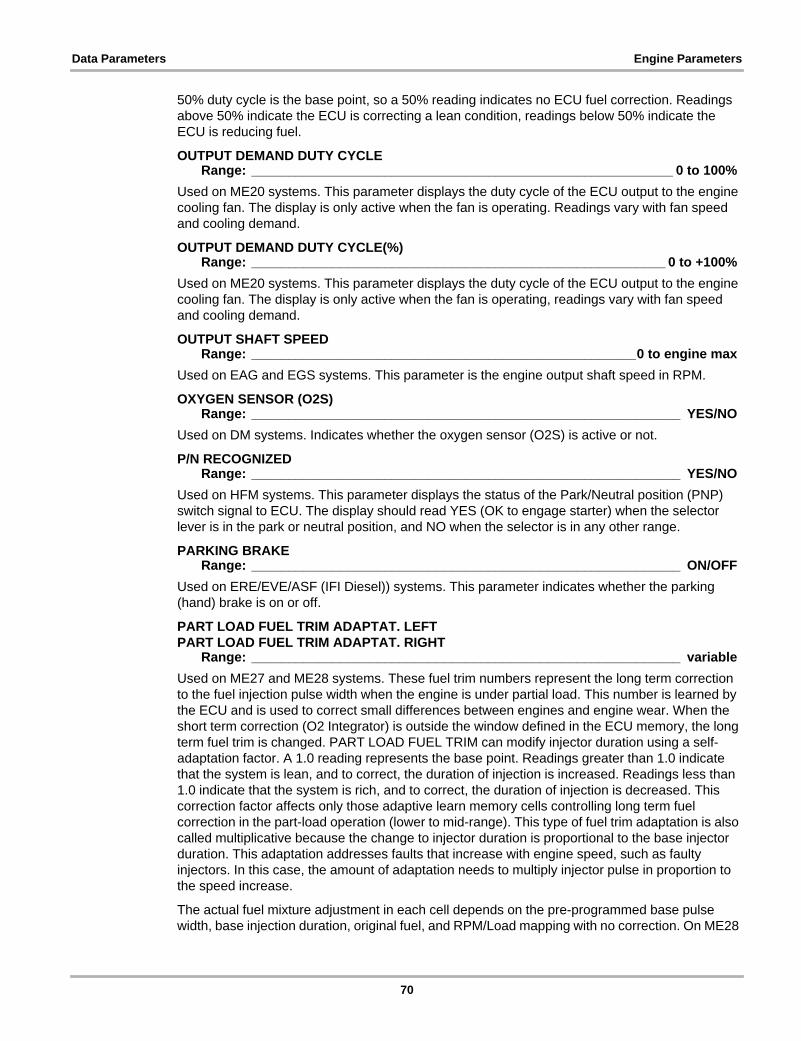
Data Parameters Engine Parameters
50% duty cycle is the base point, so a 50% reading indicates no ECU fuel correction. Readings above 50% indicate the ECU is correcting a lean condition, readings below 50% indicate the ECU is reducing fuel.
OUTPUT DEMAND DUTY CYCLERange: _________________________________________________________ 0 to 100%
Used on ME20 systems. This parameter displays the duty cycle of the ECU output to the engine cooling fan. The display is only active when the fan is operating. Readings vary with fan speed and cooling demand.
OUTPUT DEMAND DUTY CYCLE(%)Range: ________________________________________________________ 0 to +100%
Used on ME20 systems. This parameter displays the duty cycle of the ECU output to the engine cooling fan. The display is only active when the fan is operating, readings vary with fan speed and cooling demand.
OUTPUT SHAFT SPEEDRange: ____________________________________________________0 to engine max
Used on EAG and EGS systems. This parameter is the engine output shaft speed in RPM.
OXYGEN SENSOR (O2S)Range: __________________________________________________________ YES/NO
Used on DM systems. Indicates whether the oxygen sensor (O2S) is active or not.
P/N RECOGNIZEDRange: __________________________________________________________ YES/NO
Used on HFM systems. This parameter displays the status of the Park/Neutral position (PNP) switch signal to ECU. The display should read YES (OK to engage starter) when the selector lever is in the park or neutral position, and NO when the selector is in any other range.
PARKING BRAKERange: __________________________________________________________ ON/OFF
Used on ERE/EVE/ASF (IFI Diesel)) systems. This parameter indicates whether the parking (hand) brake is on or off.
PART LOAD FUEL TRIM ADAPTAT. LEFTPART LOAD FUEL TRIM ADAPTAT. RIGHT
Range: __________________________________________________________ variableUsed on ME27 and ME28 systems. These fuel trim numbers represent the long term correction to the fuel injection pulse width when the engine is under partial load. This number is learned by the ECU and is used to correct small differences between engines and engine wear. When the short term correction (O2 Integrator) is outside the window defined in the ECU memory, the long term fuel trim is changed. PART LOAD FUEL TRIM can modify injector duration using a self-adaptation factor. A 1.0 reading represents the base point. Readings greater than 1.0 indicate that the system is lean, and to correct, the duration of injection is increased. Readings less than 1.0 indicate that the system is rich, and to correct, the duration of injection is decreased. This correction factor affects only those adaptive learn memory cells controlling long term fuel correction in the part-load operation (lower to mid-range). This type of fuel trim adaptation is also called multiplicative because the change to injector duration is proportional to the base injector duration. This adaptation addresses faults that increase with engine speed, such as faulty injectors. In this case, the amount of adaptation needs to multiply injector pulse in proportion to the speed increase.
The actual fuel mixture adjustment in each cell depends on the pre-programmed base pulse width, base injection duration, original fuel, and RPM/Load mapping with no correction. On ME28
70

Data Parameters Engine Parameters
systems, the data parameter display ranges from 0.680 to 1.320; on ME27 systems, from 0.750 to 1.280.
PEDAL VALUE SENSOR SIGNAL 1PEDAL VALUE SNSR REF.POT.MTR R1PEDAL VALUE SENSOR SIGNAL 2PEDAL VALUE SNSR REF.POT.MTR R2
Range: ________________________________________________________ 0 to 5.00 VUsed on ME10, ME20, ME27, ME28, and SIM4 systems. These parameters display the ECU input signals from the pedal position and electronic throttle actuator sensors. This is a drive-by-wire system with no mechanical throttle linkage. An electronic actuator controls the throttle valve to regulate the idle speed, cruise control operation, driving on the basis of accelerator position, traction control system, Electronic Stability Program (ESP), and emergency running. The accelerator pedal position is detected by two potentiometers that transmit input signals to the ECU. Based on these signals, the ECU controls the electronic throttle actuator. One pot is in the pedal value sensor and the other is in the electronic actuator. The throttle actuator supplies a reference value for a plausibility check. If one pot fails, the system switches to the other one. The voltages from both pots should change simultaneous with throttle change. The display should read between 0.2 and 0.5 volts (V) at idle. Typical normal readings at idle for Sensor 1 are 0.20 to 0.50V; Sensor 2 are 0.10 to 0.40V. At wide open throttle (WOT), typical normal readings for Sensor 1 are 4.30 to 4.80 V; Sensor 2 are 2.10 to 2.50V.
PEDAL VALUERange: ________________________________________________________ 0 to 5.00 V
Used on HFM systems. This parameter displays the ECU input signal from the pedal position sensor. Voltage varies according to operating conditions. The HFM system does not use a drive by wire electronic throttle actuator. Instead, a mechanical throttle linkage connects to an electronic actuator on the throttle body. The actuator has an integral clutch that overrides the mechanical linkage under certain conditions. The System controls idle, cruise control, and accelerator slip regulation (ASR), which is controlled by the EA/CC/ISC module.
PRESSURE CONTROLRange: __________________________________________________________ ON/OFF
Used on ERE_EVE_ASF (IFI Diesel). This parameter should read ON whenever turbo boost is controlled by the ECU. The boost pressure transducer is actuated by the ECU with variable current which regulates the boost pressure vacuum unit. The pressure control valve is closed by the boost pressure control valve vacuum transducer through the vacuum unit which directs exhaust gas against turbine wheel.
PURGE CONTROLRange: __________________________________________________________ ON/OFF
Used on ME27 and ME28 systems. This parameter indicates whether the purge control valve is on or off.
PURGE FACTOR F 1PURGE FACTOR F 2PURGE FACTOR F 3PURGE FACTOR F 4
Range: _________________________________________________________ 0 to 100%Used on HFM systems. These parameters display the opening of the canister purge valve as a percentage.
71
Data Parameters Engine Parameters
PURGE VALVE DUTY CYCLERange: __________________________________________________________ variable
Used on HFM, ME10, ME20, ME27, and ME28 systems. The range varies by system:
• HFM; 5 to 15%• ME10; 0 to 20%• ME20; 0 to 20%• ME27; 0 to 95%• ME28; 0 to 95%
These parameters display the duty cycle of the purge valve, which is the amount of on time the ECU is commanding. The display is only active when the purge valve is open (ON) and the value varies with operating conditions, but should always be within the specified range.
PURGINGRange: __________________________________________________________ ON/OFF
Used on DM, ME10, and ME20 systems. This parameter displays the status of the evaporative emissions (EVAP) purge valve. The display reads ON with the valve open and purge activated, and OFF with the valve closed and purge deactivated. When the display reads ON, the PURGE VALVE ON-OFF RATIO/DUTY CYCLE parameter should be displaying a value.
REAR AXLE SPEEDRange: ___________________________________________________ 0 to vehicle max
Used on ME27 and ME28 systems. This parameter indicates the speed of the rear axle based on input signals to the ECU from the wheel speed sensors. The measurement units can be changed from KPH to MPH.
RECIRCULATED AIR FLAP POSITIONRange: _________________________________________________________ 0 to 100%
Used on ME20 and SIM4 systems. This parameter indicates the opening of the air flap as a percentage. The air flap controls supercharger boost and the signal is pulse-width modulated. At 0% the air flap is fully open and at 100% it is completely closed. At 11 to 99% boost control it is in part load range; and at 10% or less the air flap is open.
REFERENCE RESISTOR VOLTAGERange: ________________________________________________________ 0 to 5.00 V
REFERENCE RESISTORRange: __________________________________________________________ variable
Used on EZ and HFM systems. These parameters indicate the value of the reference resistor used for determining the internal fuel injection and ignition maps of the ECU. Up to seven resistors with different calibrations can be activated by relocating plugs in a housing with an integral resistance matrix. This permits adapting ignition-timing characteristics for different fuel types. The RON (Research Octane Number) is the anti-knock quality of fuel. The higher the number, the greater the resistance to knocking. Ignition timing can be retarded from 4 to 6 degrees, depending on whether RON 91 or 89 fuel is being used.
72

Data Parameters Engine Parameters
RESONANCE FLAP INT. MANIF. ACTUALRESONANCE FLAP INTAKE PIPE ACTUAL
Range: ____________________________________________________ OPEN/CLOSEDRESONANCE FLAP INT. LINE NOM.RESONANCE FLAP INT. MANIF. NOMINALRESONANCE FLAP INTAKE PIPE NOMINAL
Range: ______________________________________________________ not availableThese parameters are used on ERE/EVE/ASF (IFI Diesel)) systems. They display the state of the two resonance flaps for the air induction system: the intake line resonance flap (nominal) and the intake manifold resonance flap (actual). The display should read OFF, flap closed, with the engine running at low speeds (610-710). It should read OPEN at 1300-2800 and read open with the engine running at high speeds (>2800).
When actuating the Inline Fuel Injection (IFI) accelerator greater than 50%, the intake line resonance flap opens. The resonance intake manifold switch delivers a signal to the IFI control module when the intake manifold resonance flap is completely open. The resonance intake pipe switch delivers a signal when the intake line resonance flap is completely open.
The pneumatically controlled resonance flap is located on the intake manifold, and effectively makes two different intake manifold lengths. At low engine speeds, resonance flap closed, air is directed into the longer intake runners. This increases low-end torque by using the ram air effect. At high engine speeds, resonance flap open, intake air is also feed into the short intake runners. This increases the volume of air to meet the higher demands of the engine.
RI ACTUATOR ACT.VALUE POT.MTR R1RI ACTUATOR ACT.VALUE POT.MTR R2
Range: ________________________________________________________ 0 to 5.00 VUsed on ME10 systems. These parameters display the ECU input signal voltage from the pedal position and electronic throttle actuator sensors. This is a drive-by-wire system with no mechanical throttle linkage. An electronic actuator controls the throttle valve under different operating conditions to regulate idle speed, cruise control operation, driving on the basis of accelerator position, traction control (Acceleration Slip Regulation), Electronic Stability Program (ESP) and emergency running. The accelerator pedal position is detected by two potentiometers that transmit input signals to the ECU. Based on these signals, the ECU controls the electronic throttle actuator. One potentiometer is in the pedal value sensor and the other is in the electronic actuator. The electronic throttle actuator supplies a reference value for a plausibility check. If one of the potentiometers fails, the system switches over to the other one. A quick check is to add both actuator signal readings (R1 and R2) together at various throttle positions. The two readings should always add up the same value, usually between 4.5 to 4.9 volts.
RIGHT O2S (LAMBDA) CONTROL ACTIVERange: __________________________________________________________ YES/NO
Used on ME10 systems. This parameter indicates whether or not the system is operating in closed loop and the ECU is responding to the right bank oxygen sensor (O2S) feedback signal. The display reads YES when operating in closed loop, and NO when in open loop.
RIGHT O2S (LAMBDA) CONTROL AUTHORIZEDRange: __________________________________________________________ YES/NO
Used on ME10 systems. This parameter indicates whether or not the ECU is allowing closed loop operation. The display reads YES when closed loop operation is allowed, and NO when the ECU is holding the system in open loop.
73

Data Parameters Engine Parameters
RIGHT O2S (LAMBDA) CONTROL FAULTRange: __________________________________________________________ YES/NO
Used on ME10 systems. This parameter indicates whether or not the ECU has recognized a failure on the left oxygen sensor (O2S), or Lambda control, circuit. The ECU prevents closed loop operation if an O2S fault is detected. The display reads NO during normal operation, a reading of YES indicates a fault is present.
RIGHT O2S (LAMBDA) CONTROL W/O O2S2Range: _______________________________________________________ –25 to +25%
Used on ME10 systems without a downstream O2S. This parameter represents the short-term fuel metering correction based on the signal of the upstream O2S on the right cylinder bank. Zero is the base setting, no correction. Positive readings indicate the ECU is correcting for a lean condition by increasing injector on time, while negative readings indicate the ECU is correcting for a rich condition by reducing injector on time.
RIGHT WOT (FULL LOAD)/DECEL.SHUT-OFFRange: __________________________________________________________ YES/NO
Used on ME10 systems. This parameter indicates if the ECU has shut off fuel delivery to the right cylinder bank to reduce emissions during deceleration. The display should read YES on deceleration following wide-open throttle (WOT), full load operation, and NO at all other times.
RON CORRECTIONRange: __________________________________________________________ variable
Used on HFM systems. This parameter indicates the ECU ignition timing adjustment for different octane fuels. The research octane number (RON) represents the anti-knock quality of fuel. The higher the RON, the greater the resistance to knocking. Depending on the system, ignition timing may retard 4 to 6 degrees to compensate for the fuel being used.
RON INDEXRange: __________________________________________________________ ON/OFF
Used on HFM systems. This is the value of the reference resistor used for determining the internal fuel injection and ignition maps of the ECU. The research octane number (RON) is the anti-knock quality of fuel at lower speeds. Motor Octane Number (MON) is the anti-knock quality of fuel at higher speeds. U.S. government legislation simplified the issue requiring pumps to post the minimum octane number determined by “Cost of Living Council” (CLC). The CLC number is derived from both RON and MON. On this system the higher the RON, the greater the resistance to knocking. Depending on the reference resistor, ignition timing may be retarded 4 to 6 degrees.
SAFETY CONTACTSAFETY FUEL SHUT-OFF
Range: __________________________________________________________ ON/OFFUsed on ERE/EVE/ASF (IFI Diesel)), HFM, LH, ME10, ME20, ME27, and ME28 systems. These parameters indicate the state of the safety contacts in the electronic accelerator actuator. The display normally reads OFF and ON when the safety contacts are closed. The ECU is connected to safety switch contacts in the electronic accelerator actuator or the cruise control/idle speed control actuator. During normal operation, the switch sends a positive signal to the ECU. If the throttle opens more than the position specified by the accelerator pedal and the cruise control is not engaged, the switch sends a ground signal to the ECU. In response, the ECU switches the fuel injectors off. Injection switches back on when engine speed drops below 1200 RPM.
74

Data Parameters Engine Parameters
SELECTED GEARRange: ______________________________________________________ P,R,N,1,2,3,4
Used on HFM, LH, ME10, and ME20 systems. This parameter indicates the gear selector lever position. The display shows the selected range position, not the current gear that the transmission is operating in.
SELECTOR LEVER POSITIONRange: ___________________________________________________________PN/RD1
Used on EGS, ERE/EVE/ASF (IFI Diesel)), HFM, LH, ME10, ME20, ME27, and ME28 systems. This parameter indicates the gear selector lever position. The display shows the selected range position, not the current gear that the transmission is operating in.
SELF-ADAPT THROTTLE VALVE-ACTRange: __________________________________________________________ variable
Used on ME27 and ME28 systems. This parameter indicates the ECU adaptation in degrees for the throttle valve actuator. This adaptation is made to compensate for wear, based on voltage signal from the throttle valve actuator potentiometer.
SELF-ADAPTATIONRange: _____________________________________ ON/OFF or ENABLED/DISABLED
Used on HFM, ME27, ME28, and SIM4 systems. This parameter indicates whether or not the ECU is attempting to compensate for tolerances in the mixture by means of long term adaptation, or long term fuel trim (LTFT) adjustments. The display only reads ON or ENABLED when the ECU is making LTFT adjustments.
SELF-ADAPTATION CTP (IDLE)Range: _____________________________________________________ –1.0 to 1.0 ms
Used on LH and ME20 systems. This is the closed throttle (idle) fuel correction the ECU is commanding to maintain a 14.7:1, or 1.0 Lambda, air-fuel ratio. The display is the adjustment in addition to base injector time. There are three different ranges in which self-adaptation, or long-term fuel trim (LTFT) is performed: closed throttle; lower part throttle, and upper part throttle. If the short-term fuel trim (STFT) or O2S Lambda control constantly drifts out of mid-control range, the ECU shifts the Lambda map to recreate a control factor of about zero. The millisecond readout is added to or subtracted from the air mass inducted by the engine for determining injector time. For example, base injector time is 3.0 ms and SELF-ADAPT CTP (IDLE) reads 0.3 ms. This means the ECU is using a computed value of 3.3 ms to determine injector duration.
SELF-ADAPTATION CTP (IDLE)Range: _________________________________________________________ ±850 kg/h
Used on LH and HFM systems. This parameter displays the closed throttle position (CTP), or idle, correction factor that the ECU is commanding. The displayed kg/h reading is added or subtracted to the AIR MASS sensor value in order to determine injection time.
For example, the SELF-ADAPTATION CTP (IDLE) reading is 0.500 kg/h and the AIR MASS sensor reading is 18 kg/h. The ECU will use a value of 18.5 kg/h to calculate the final injection quantity, thus compensating for a lean mixture. Positive values are added to the AIR MASS sensor reading and negative values are subtracted from the reading.
SELF-ADAPTATION DELAY TIMERange: _____________________________________________________ –1.0 to 1.0 ms
Used on ME20 systems. This parameter is the adaptation for injector delay time, which is supplementary injection duration based on battery voltage. Injector duration varies according to battery voltage. There can be substantial time lag before the injector opens completely, especially during cold starts or with a partially discharged battery. The display is the supplementary injector time added to the base duration to compensate.
75

Data Parameters Engine Parameters
SELF-ADAPTATION IDLE SP. AIRRange: _____________________________________________ X.XX kg/h or –15 to 15%
Used on LH and HFM systems. This parameter displays the closed throttle position (CTP), or idle, correction factor that the ECU is commanding to maintain a steady idle. The display for most systems is in kilograms per hour (kg/h) with zero being the base point. On some HFM systems, a percentage is displayed. For all systems, negative readings indicate the ECU is decreasing the idle valve opening and positive values indicate an increase in idle valve opening. The data mass variable is kilograms per hour (kg/h).
SELF-ADAPTATION, IDLE SPEEDRange: ___________________________________________________ –0.50 to 0.50 ms
Used on SIM4 systems. This fuel trim number represents the fine tuning long-term correction to the fuel injection pulse width. This type of long term fuel trim adjustment is also called Additive Mixture Adaptation because it can modify the duration of injection by adding or subtracting to the base injection time in each fuel map cell (affects all cells by the same amount). It thus affects the entire engine speed range or all fuel map cells, but is most noticeable at idle because of the minimal amount of adjustment capability. This number is learned by the ECU and used to correct small differences between engines and engine wear.
When the short term correction is outside the window defined in the ECU memory, the long term fuel trim is changed. Each change in the Long Term Fuel Trim is equivalent to a change of the Short Term Fuel Trim over its entire range. When the Short Term Fuel Trim reaches its upper/lower limit, it resets back to the beginning, and moves Long Term Fuel Trim up or down by one count. The Short Term Fuel Trim continues to move very quickly and if the limits are reached, it again will increment the Long Term Fuel Trim. This continues until either the fuel mixture problem is corrected or long-term correction reaches its limit and a DTC is set.
SELF-ADAPTATION, IDLE SPEEDRange: ___________________________________________________ –0.50 to 0.50 ms
Used on SIM4 systems. This parameter displays the closed throttle position (idle) fuel correction to maintain a 14.7:1, or 1.0 Lambda, air-fuel ratio. The display is the adjustment made in addition to basic injector on time. If short-term fuel trim (STFT) or O2S Lambda control constantly drifts out of mid-control range, the ME control module shifts this long-term Lambda map to recreate a control factor of about 0 ms. This is also called Additive Mixture Adaptation because it can modify the duration of injection by adding or subtracting to the base injection time in each fuel map cell. It thus affects the entire engine speed range or all fuel map cells, but is most noticeable at idle because of the minimal amount of adjustment capability.
SELF-ADAPTATION PARTIAL LOADRange: ________________________________________________________ –25 to 25%
Used on SIM4 systems. These parameters represent the long-term fuel metering correction required to maintain a stoichiometric (14.7:1), or 1.0 Lambda, air-fuel ratio. Fuel corrections are based on the indicated O2S signals and short term fuel trim. Positive readings indicate increased injector duration to correct a lean condition, and negative readings indicate reduced on time to correct a rich condition.
This is a long-term correction factor applied to the pre-programmed low partial load base cell values (original fuel, RPM/Load mapping with no correction).
SELF-ADAPTATION UPPER PART. LOADRange: ________________________________________________________0.85 to 1.15
Used on LH systems. This parameter indicates the upper partial load self-adaptation factor, which is one of three factors that the ECU uses to make long-term fuel trim (LTFT) corrections to maintain a 14.7:1, or 1.0 Lambda, air-fuel ratio. On the display, a 1.0 reading is the base point. Readings over 1.0 are a rich correction, or increased injector time and readings lower than 1.0
76

Data Parameters Engine Parameters
are a lean correction, or reduced injector time. The ECU attempts to compensate for tolerances in the mixture by means of LTFT adjustments. All corrections are made in three ranges: closed throttle position, lower partial load, and upper partial load. The ECU multiplies the actual mass of the air inducted into the engine by the correction factor to determine the injection time. For example, if the actual air mass is 150 kg/h and the Scanner reading is 1.10, a computed air mass value of 165 kg/h (150 x 1.1 = 165) is used for injection time.
SELF-ADAPT. CTP (IDLE) LEFTSELF-ADAPT. CTP (IDLE) RIGHT
Range: _____________________________________________________ –1.0 to 1.0 msUsed on ME10 and ME20 systems. These parameters display the closed throttle position (idle) fuel correction for the indicated cylinder bank the ECU is commanding to maintain a 14.7:1, or 1.0 Lambda, air-fuel ratio. The display is the adjustment made in addition to basic injector on time. There are three ranges in which self-adaptation, or long-term fuel trim (LTFT) is performed: closed throttle; lower part throttle, and upper part throttle. If short-term fuel trim (STFT) or O2S Lambda control constantly drifts out of mid-control range, the ME control module shifts the Lambda map to recreate a control factor of about 0%. Idle speed-learn, or SELF-ADAPT, is in millisecond output. The readout is added to or subtracted from the air mass inducted by the engine for determining injector time. For example, base injector time is 3.0 ms and SELF-ADAPT CTP (IDLE) LEFT reads 0.3 ms. This means that the ECU is using a computed value of 3.3 ms for determining injection time on the left bank.
SELF-ADAPT. DELAY TIME LEFTSELF-ADAPT. DELAY TIME RIGHT
Range: _____________________________________________________ –1.0 to 1.0 msUsed on ME10 and ME20 systems. These parameters display the left and right cylinder bank adaptation for injector delay time. Delay time is supplementary injection duration based on battery voltage. Injector duration varies according to battery voltage and there can be substantial time lag before the injector opens completely, especially during cold starts or with a partially discharged battery. The display represents the supplementary injector on time in (ms) that is being added to the base duration to compensate for this effect on the left cylinder bank.
SELF-ADAPT. FACTOR LOWER PART. LOADSELF-ADAPTATION LOWER PART. LOADSELF-ADAPTATION PARTIAL LOAD
Range: ________________________________________________________0.85 to 1.15Used on LH and HFM systems. This parameter displays the lower partial load self-adaptation factor, which is one of three factors the ECU uses to make long-term fuel trim (LTFT) corrections to maintain a 14.7:1, or 1.0 Lambda, air-fuel ratio. A 1.0 reading represents the base point. Readings greater than 1.0 indicate a rich correction, or increased injector time, and readings below 1.0 indicate a lean correction, or reduced injector time. The HFM-SFI control module attempts to compensate for tolerances in the mixture by means of LTFT adjustments. All corrections are made in three ranges: closed throttle position, lower partial load and upper partial load. The ECU multiplies the actual mass of the air inducted into the engine by the displayed correction factor to determine the injection time. For example, if the actual air mass is 150 kg/h and the Scanner reading is 1.10, a computed value of 165 kg/h (150 x 1.1 = 165) is being used.
SELF-ADAPT.PART. LOAD FACTOR RIGHTSELF-ADAPT.PART. LOAD FACTOR LEFT
Range: __________________________________________________________ variableUsed on ME10 (0.77–1.28 range) and ME20 (0.68–1.32 range) systems. These parameters display the lower partial load self-adaptation factor for the indicated cylinder bank. Lower partial load self-adaptation factor is one of three factors the ECU uses to make long-term fuel trim (LTFT) corrections to maintain a 14.7:1, or 1.0 Lambda, air-fuel ratio. A 1.0 reading represents
77
Data Parameters Engine Parameters
the base point, or no correction. Readings above 1.0 indicate a rich correction, or increased fuel, and readings below 1.0 indicate a lean correction, or reduced fuel. All corrections are made in three ranges: closed throttle position, lower partial load and upper partial load. The ECU multiplies the actual mass of the air inducted into the engine by the correction factor (% positive or negative) to determine the injection time. For example, if the actual air mass is 150 kg/h and the Scanner reading is 1.10 (positive 10%), a computed air mass value of 165 kg/h (150 x 1.1(10%) = 165) is used for injection time.
The MIL will come on when self-adaptation reaches the range limit.
SENSITIZATION FACTORSENSOR GEAR FILTER 1SENSOR GEAR FILTER 2
Range: ______________________________________________________ not availableSNSR GEAR ADAPT. MEAN VALUES SEG. A TO E
Range: __________________________________________________________ variableSENSOR ROTOR ADAPTATIONSENSOR ROTOR ADAPTATION COMPLETED
Range: __________________________________________________________ YES/NOThese parameters are all related to crankshaft sensor misfire detection sensitization. An adaptation procedure to enhance the sensitization and reduce false misfire reporting is used on some models.
Sensor Gear (Flywheel) adaptation may be required on ME-SFI 1.0, 2.0, 2.1, and 2.8. Sensor Gear adaptation started approximately in 1998 with the ML 112/113 engines. Later ME 2.8 and SIM4 may also use this function. The adaptation re-configures the ME controller for increased sensitivity for misfire detection.
Drive train influences on misfire detection are:
• crankshaft flex• motor mount movement • torque converter lock-up operation• automatic transmission shift characteristics• drive shaft and differential vibration
Misfire detection using the crankshaft position sensor requires sensor gear adaptation whenever the following components are replaced:
• flywheel or starter ring gear• crank sensor (L/5)• ECU• motor mounts
In some cases, sensor gear adaptation must be performed after a misfire code.
The engine is constantly monitored for misfire to protect the catalytic converter. The engine is analyzed by evaluating the crankshaft position sensor using a sophisticated mathematical method to determine whether precise time synchronism exists between individual combustions. Each individual combustion must produce a characteristic acceleration at the flywheel. If misfire occurs, flywheel rotation slows slightly. These parameters are the amount of correction the ECU is making to filter out vibration and prevent setting false misfire codes. The ECU sets irregular engine running analysis or misfire detection to a less sensitive setting when driving on a poor road surface. The body acceleration sensor, or electronic vibration module, detects a rough road and sends this information to the ECU. The misfire sensitivity level can also be altered with the
78

Data Parameters Engine Parameters
Scanner as a Functional Test. A lower threshold enables the ECU to detect less severe misfires indicated by reading the RPM decrease and misfire fault counter for each cylinder.
The crankshaft sensor gear adaptation mean value reflects the addition of a supplementary correction factor designed to compensate for phase error in the crankshaft sensor. This information is used to compute actual ignition timing. Each segment represents the duration between each new ignition cycle. Ignition, injection and engine speed derived from segment duration are recalculated for each segment.
SENSOR GEAR ADAPTATION ENDEDRange: __________________________________________________________ YES/NO
Used on ME and SIM4 systems. This parameter indicates whether the sensor gear adaptation memory has been cleared. The display reads YES if the adaptation has ended and NO if adaptation memory has run and is active. Sensor gear adaptation memory is cleared when the Scanner performs an ECU reset functional test command.
SHIFT POINT SHIFTRange: ______________________________________________________ not available
Used on HFM systems. This parameter indicates the transmission shift point variability. No other information is available at this time.
SNSR GEAR ADAPT. MEAN VAL. SEG.A to E; N1 to N4SNSR GEAR ADAPT. MEAN VALUES SEG.A to E
Range: ____________________________________________________ range: variableUsed on ME10 systems. This parameter indicates the correction the ECU is making to filter out vibrations and prevent setting false misfire codes.
The crankshaft sensor gear adaptation mean value reflects the addition of a supplementary correction factor designed to compensate for phase error in the crankshaft sensor. This information is used to compute actual ignition timing. Each segment represents the duration between each new ignition cycle. Ignition, injection, and engine speed derived from segment duration are recalculated for each segment.
SMOOTH RUNNING OF CYL. 1 to 8Range: __________________________________________________________ variable
Used on ME27 and ME28 systems. The “1 to 8" represents eight separate parameters, one for each cylinder. These parameters indicate cylinder detonation, or knock, as provided to the ECU by the various knock sensors. The ECU calculates a new value once per second. The measurement is the actual knock sensor frequency output. High numbers on individual cylinder(s), may indicate a specific problem limited to that cylinder(s). High numbers on all cylinders may indicate a general engine detonation or pinging problem.
SP.DEV.BT. FR/RR AXLES TOO HIGHRange: __________________________________________________________ YES/NO
Used on HFM systems. This parameter shows whether the ECU is receiving input signals indicating too much deviation between the speed of the front and rear axles. The display reads YES if speed deviation is too high, and reads NO at all other times. Traction control activates when YES displays.
SPEED SIGNALRange: __________________________________________________________ variable
Used on DM systems. This parameter is the vehicle speed sensor (VSS) input signal to the ECU.
79

Data Parameters Engine Parameters
START APPROVALRange: __________________________________________________________ YES/NO
Used on LH systems. This shows whether the ECU will allow starting based on input from the anti-theft system. The display reads YES if the correct input from the anti-theft system is received, and NO if the incorrect input signal was received and startup is being prevented.
START ATTEMPT MADE WITH DAS LOCKEDRange: __________________________________________________________ YES/NO
Used on ME and SIM4 systems. This parameter indicates whether an attempt to start the engine was made with the drive authorization system (DAS) or anti-theft system locked. The display normally reads NO and only reads YES if there was a start attempt with the DAS or anti-theft system locked. The ECU and DAS module are permanently interlocked by means of an identification code that cannot be erased. Therefore, it is not possible to interchange control modules from another vehicle for test purposes. Control model interchanges can only be performed using a matched pair of control modules. The ME-SFI module is equipped with an immobilizer. When the vehicle is locked, the DAS transmits a signal to the ME-SFI on the CAN bus that inhibits injection. The engine can start only when the vehicle is unlocked with the authorized key, and when the DAS control module transmits a start enabled signal to the ME-SFI control module.
START ATTEMPT W.IMPLAUS.INPUT SIGNRange: __________________________________________________________ YES/NO
Used on LH systems. This parameter indicates whether an attempt to start the engine was made with the anti-theft system locked. The display normally reads NO, and only reads YES if there was a start attempt with the anti-theft system locked.
START AUTHORIZATIONRange: __________________________________________________________ YES/NO
Used on ERE/EVE/ASF (IFI Diesel)), HFM, ME, and SIM4 systems. This parameter indicates whether the drive authorization system (DAS), or anti-theft system, and the engine control module (ECU) have correctly identified each other. The display reads YES at startup if the modules correctly identify each other. A NO reading indicates the modules cannot identify each other and starting is disabled. The ECU and DAS module are permanently interlocked by means of an identification code that cannot be erased. Therefore, it is not possible to interchange control modules from another vehicle for test purposes. Control model interchanges can only be performed using a matched pair of control modules. The ME-SFI module is equipped with an immobilizer. When the vehicle is locked, the DAS transmits a signal to the ME-SFI on the CAN bus that inhibits fuel injection. The engine can start only when the vehicle is unlocked with the authorized key and the DAS control module transmits a start enabled signal to the ME-SFI control module.
START OF INJECTIONRange: ______________________________________________________ not available
Used on ERE_EVE_ASF (IFI Diesel)). This parameter indicates the actual start of injection (RI value, start of delivery after TDC) in degrees. Adjustment is performed on main injection pump using an injection timing tester.
80

Data Parameters Engine Parameters
STARTER CONTROLRange: __________________________________________________________ YES/NO
STARTER LOCK-OUT OUTPUTSTARTER LOCK-OUT REED CONTACTSTARTER LOCK-OUT STATUS
Range: __________________________________________________________ ON/OFFUsed on HFM and EGS systems. These parameters indicate whether the immobilizer system is locking out the starter system. The display reads YES/ON if the starter system is disabled.
STARTER SIGNAL CIRCUIT 50Range: __________________________________________________________ ON/OFF
Used on HFM systems. This parameter indicates the state of circuit 50, which is the starter circuit. The display reads ON when the starter is cranking, then switches to OFF after the engine starts.
STOP LAMP SWITCHRange: __________________________________________________________ ON/OFF
Used on ME10, ME20, ME27, ME28 and SIM4 systems. This parameter indicates the state of the brake light switch. The display reads ON if the brake light switch circuit is closed, brake lights on, and OFF when the circuit is open.
STOP LAMP SWITCH N.C. CONTACTSTOP LAMP SWITCH N.O. CONTACT
Range: __________________________________________________________ ON/OFFUsed on ERE_EVE_ASF (IFI Diesel)). No information is available.
SUPERCHARGER CLUTCHRange: __________________________________________________________ ON/OFF
Used on ME20 systems. This parameter indicates the state of the supercharger clutch. The display reads ON if the supercharger clutch is engaged to increase boost, and OFF when the clutch is disengaged.
SUPERCHARGER EFFICIENCY FACTORRange: __________________________________________________________ variable
Used on ME20 systems. This parameter indicates the ECU-calculated supercharger efficiency factor, which reflects supercharger performance. Readings vary with speed and load. Typically, if driving in third gear at 3500 RPM under full load, the reading should be greater than 1.3.
TANK FILL LEVELRange: _______________________________________________________ OK/NOT OK
Used on ME20 systems. This parameter indicates whether there is the proper amount of fuel in the fuel tank to run an evaporative emissions (EVAP) test. The display reads OK if the fuel level is within test range and NOT OK if the fuel level outside the test range.
TANK PRESSURE DIFFERENCERange: __________________________________________________________ variable
Used on ME10 and ME20 systems. This parameter, which displays in millibar (mbar), indicates the results of an ECU-performed fuel tank leak test. This test is part of the OBD-II monitoring system. The fuel tank pressure test uses an internal fuel tank pressure sensor.
To perform this leak test, the ECU closes the canister shut-off valve to the activated charcoal canister and opens the purge control valve. This allows intake manifold vacuum into the fuel tank, where it is detected by the fuel tank pressure sensor. Tank pressure difference must read about -7 mbar within about 10 seconds or a major leak exists. If no major leak is detected, the
81

Data Parameters Engine Parameters
ECU closes the purge control valves and monitors vacuum for 30 seconds to ensure there is no decrease due to a minor leak.
TEMPOMAT SWITCHTEMPOMAT SWITCH(ACCELERATE)TEMPOMAT SWITCH(DECELERATE)TEMPOMAT SWITCH(STORE)
Range: __________________________________________________________ ON/OFFUsed on ME10 and ME20 systems. These parameters indicate the state of the cruise control switch. The display reads ON when the indicated switch is energized, and OFF if it is not.
THROTTLE VALVE ACTUATOR SIGN. 1THROTTLE VALVE ACTUATOR SIGN. 2
Range: ________________________________________________________ 0 to 5.00 VUsed on ME27, ME28, and SIM4 systems. These parameters indicate throttle opening angle in volts based on the input signal of the throttle valve actuator signals. Readings vary with throttle opening. This drive-by-wire system has no mechanical throttle linkage. An electronic actuator controls the throttle valve under different operating conditions to regulate idle speed, cruise control operation, driving on the basis of accelerator position, traction control (Acceleration Slip Regulation), Electronic Stability Program (ESP), and emergency running. The position of the accelerator pedal is detected by two potentiometers that transmit input signals to the ECU. Based on these signals, the ECU controls the electronic throttle actuator. One potentiometer is the pedal value sensor and the other one is the electronic actuator. The electronic throttle actuator potentiometer supplies a reference value for a plausibility check. In an emergency, if one potentiometer fails, the system switches over to the second one. A quick plausibility check is to add both actuator signal readings (SIGNAL 1 and SIGNAL 2) together at various throttle positions. They should always add up the same value, usually between 4.5 to 4.9 volts.
THROTTLE VALVE ANGLETHROTTLE VALVE POSITION
Range: __________________________________________________________ variableUsed on DM2, HFM, LH, ME10, ME20, ME27, ME28, and SIM4 systems. These parameters indicate throttle opening angle in degrees based on the input signal of the throttle valve potentiometer. Readings vary with throttle opening. Normal idle range is 0.3 to 2.5 degrees for all engines except the 111. Normal idle range for the 111 engine is 1.8 to 3.5 degrees.
THROTTLE VALVE STOP LEARNEDRange: __________________________________________________________ YES/NO
Used on ME10, ME20, ME27, ME28, and SIM4 systems. This parameter indicates whether or not the ECU has gone through the correct learn procedure for the throttle valve stop setting and has adjusted the idle accordingly. The display reads YES if the ECU completed the throttle valve stop learn procedure and successfully adjusted the idle speed. A reading of NO indicates the ECU has not successfully executed the throttle stop learn procedure.
TIME SINCE STARTRange: __________________________________________________________ variable
Used on ME10 systems. This is a clock that displays the elapsed time of engine running since the last start. The timer resets with each key cycle.
TOP SPEED LIMITATIONRange: __________________________________________________________ ON/OFF
Used on ERE-EVE_ASF (IFI Diesel)). This parameter reads ON when the ECU has engaged the Engine Maximum Speed Governing System. The control unit detects the engine speed and adjusts the fuel rack to approximately 5400 RPM (no engine load).
82

Data Parameters Engine Parameters
TORQUETORQUE CORR. VALUE DURING SHIFTTORQUE DIFFERENCE SUMTORQUE LOSS
Range: __________________________________________________________ variableUsed on EGS, ME10, and ME20 systems. This parameter is an ECU-calculated engine torque shown in newton-meters (Nm). Display varies according to engine load. The ME-MOTRONIC engine management uses torque-led control, which means it calculates the internal torque produced during combustion. This is the physical force produced by gas pressure during the compression and power strokes. The actual net torque of the engine has to account for friction, gas transfer losses, and drive power for equipment such as the water pump, alternator, and AC compressor. The ME program contains the optimal specifications for charge density, injection duration, and ignition timing for any desired torque. This makes it possible to obtain optimal emissions and fuel consumption for every operational mode. Operational demands are prioritized and coordinated individually to use the appropriate control to achieve the specified torque. Torque based control is possible because the electronic accelerator permits throttle valve control beyond the pedal value inputs.
TRANSM. OVERLOAD PROTEC. SWITCHTRANSMISSION OVERLOAD PROTECTIONTRANSMISSION OVERLOAD PROTECTION INTERTRANSMISSION PROTECTION
Range: __________________________________________________________ ON/OFFUsed on EZ, HFM, ME10, ME20, ME27, and ME28 systems. These parameters show whether or not the ECU is operating the automatic transmission in an overload protection mode. The display normally reads OFF and reads ON if transmission overload protection mode is active. In overload mode the ECU disables the torque converter clutch and overdrive.
TRANSMISSION SHIFT DELAYTRANSMISSION UPSHIFT DELAYUPSHIFT DELAY 1
Range: __________________________________________________________ ON/OFFUsed on LH, HFM, and ME20 systems. This parameter indicates whether the ECU shift delay program is active. The display reads OFF during normal operation, and ON if the ECU is delaying upshifts to more rapidly heat up the catalytic converter after a cold startup.
TRIP SINCE ERASING FAULTRange: ___________________________________________________________0 to 255
Used on ME10 systems. This parameter indicates the number of trips since a specified diagnostic trouble code was erased.
TWC HEATING AT IDLERange: __________________________________________________________ ON/OFF
Used on HFM, ME10, and ME20 systems. This parameter indicates the state of the three-way catalyst (TWC) heating circuit. During normal operation the Scanner should display OFF, and at a cold startup or during prolonged idle, the Scanner should display ON. The TWC contains an electric heating element to help it maintain optimal temperature for reducing emissions. The ECU energizes the heater if internal temperatures drop below a preset threshold during prolonged idle. The heater is also energized at cold startup when the catalytic converter temperature is below 86°F (30°C). The ECU activates the electric TWC heater for a maximum of 50 seconds during one cycle.
83

Data Parameters Engine Parameters
TWC TEMPERATURE FROM OBD 2Range: __________________________________________________________ variable
Used on HFM systems. This parameter displays the ECU-calculated temperature of the three-way catalyst (TWC) for OBD-II vehicles.
UPPER P. LOAD F. TRIM CYL 1-6, RIGHTUPPER P. LOAD F. TRIM CYL 4-6, RIGHTUPPER P. LOAD F. TRIM CYL 7-9, LEFTUPPER P. LOAD F. TRIM CYL 10-12, LEFT
Range: ______________________________________________________0.750 to 1.280Used on ME2.7 systems. This parameter is the upper partial load self-adaptation correction factor that the ECU uses to make long-term fuel trim (LTFT) corrections to maintain a 14.7:1, or 1.0 Lambda, air-fuel ratio. This is a long-term correction factor applied to the pre-programmed upper partial load base cell values (original fuel, RPM/Load mapping with no correction). On the display, a 1.0 reading is the base point. Readings over 1.0 are a rich correction, or increased injector time and readings lower than 1.0 are a lean correction, or reduced injector time. This correction factor affects only those adaptive learn memory cells controlling long term fuel correction in the upper-load operation.
UPSHIFT DELAY 2ND GEARRange: __________________________________________________________ ON/OFF
Used on LH systems. This parameter indicates whether or not the ECU shift delay program for second gear is active. This value normally reads OFF. The display only reads ON if the ECU is holding the transmission in second gear to more rapidly heat up the catalytic converter following a cold engine start.
VARIABLE SPEED LIMITATIONRange: __________________________________________________________ variable
Used on ME27 and ME 28 systems. Range may be ON/OFF or ACTIVE/NOT ACTIVE. No information is available at this time.
VEHICLE LOCKED WITH DASRange: __________________________________________________________ YES/NO
Used on ERE/EVE/ASF (IFI Diesel)) and ME10 systems. This parameter indicates whether the drive authorization system (DAS) and the engine control module (ECU) have correctly identified each other. The display reads YES at startup if the modules correctly identify each other and NO if they do not. The ECU and DAS module are permanently interlocked by means of an identification code that cannot be erased. It is not possible to interchange modules from another vehicle for test purposes. Module interchanges can only be made using a matched pair of modules. Also, the ME-SFI module has an immobilizer. When the vehicle is locked, the DAS transmits a signal to the MESFI on the controller area network (CAN) bus that inhibits injection. The engine only starts if the vehicle is unlocked with the authorized key and the DAS module transmits a start enable signal to the ME-SFI module.
VEHICLE SPEEDRange: ___________________________________________________ 0 to vehicle max
Used on CD12, DM, DM2, EGS, ERE/EVE/ASF (IFI Diesel)), HFM, LH, and SIM4 systems. This parameter indicates the speed of the vehicle based on input signals to the ECU from the wheel speed sensors. The measurement can be changed from kilometers per hour (KPH) to miles per hour (MPH).
84

Data Parameters Engine Parameters
VEHICLE SPEED FRONT AXLEVEHICLE SPEED REAR AXLE
Range: ___________________________________________________ 0 to vehicle maxUsed on ME 10, ME 20 and SIM4 systems. These parameters indicate the speed of the front and rear axles based on input signals to the ECU from the wheel speed sensors. The measurement can be changed from kilometers per hour (KPH) to miles per hour (MPH).
VEHICLE SPEEDVEHICLE SPEED SIGNAL (VSS)VSS
Range: ___________________________________________________ 0 to vehicle maxUsed on DM, DM2, HFM, LH, and ME10 systems. This parameter indicates the vehicle speed based on the vehicle speed sensor (VSS) input signal to the ECU. Measurement units can be changed from kilometers per hour (KPH) to miles per hour (MPH).
VMIN NOT MAINTAINEDRange: __________________________________________________________ YES/NO
Used on HFM systems. This parameter indicates if the charging system is maintaining the minimum required voltage. The display reads NO during normal operation and reads YES when charging system output falls below the minimum voltage requirement.
WARM-UPRange: __________________________________________________________ ON/OFF
Used on HFM and LH systems. This parameter indicates whether or not the ECU is operating the engine in warm-up mode following a cold start. The display reads OFF during normal driving with a warm engine, and ON from a cold start with engine in warm-up mode.
WOT (FULL LOAD) CONTACTWOT (FULL LOAD) INFO. LOADWOT (FULL LOAD) RECOGNITIONWOT (FULL LOAD)
Range: __________________________________________________________ ON/OFFUsed on DM2, HFM, LH, ME10, and ME20 systems. This parameter indicates the state of the wide-open throttle (WOT) switch. The display reads OFF during normal driving and reads ON with throttle at wide open under full load acceleration.
WOT (FULL LOAD) INFO.THR.VLV.POSRange: __________________________________________________________ ON/OFF
Used on DM2 systems This parameter shows the state of the wide-open throttle (WOT) switch. The Scanner displays OFF during normal driving, and ON during operation at wide open throttle under full load acceleration. The ECU relies on the electronic accelerator actuator input signal to determine whether the engine is at full load acceleration.
85

Data Parameters Transmission Parameters
Transmission Parameters5TH GEAR
Range: __________________________________________________________ ON/OFFUsed on the EAG system. This parameter indicates whether the electronic transmission controller (ETC) has engaged 5th gear (overdrive). ON means that overdrive is engaged.The 4th to 5th gear upshift at full throttle may not occur until reaching the cutoff speed. This means that under full throttle conditions, high-powered vehicles may not shift into fifth gear below 155 mph (250 km/h).
3RD GEAR DOWN3RD GEAR UP4TH GEAR DOWN4TH GEAR UP5TH GEAR DOWN5TH GEAR UP
Range: ______________________________________________________ not availableUsed on the EGS system. Do not use at this time.
ACCELERATOR PEDAL(%)Range: _________________________________________________________ 0 to 100%
Used on the EGS system. This parameter is derived from a CAN signal via the engine management system. When the accelerator pedal is not depressed, the parameter value is 0 percent. With the pedal fully depressed in the kick-down position, the value rises to 100 percent.
The CAN is a broadcast type of bus. This means that all modules “hear” all transmissions. There is no way to send a message to just a specific module; all modules invariably pick up all traffic. However, CAN hardware provides local filtering so each module reacts only to data whose identifiers are stored in its acceptance list. This very high frequency transmission requires a “twisted pair” of wires to address electromagnetic interference (EMI) concerns. Two wires also ensure communication if one wire is damaged and provide the ability to recognize a CAN circuit fault. The two lines must not be interchanged as each represents either a high or low level.
ACCELERATOR PEDAL DELAY(%)Range: _________________________________________________________ 0 to 100%
Used on the EGS system. No information is available at this time.
ACTUAL GEARRange: ______________________________________________ P, R, R2, N, 5, 4, 3, 2, 1
Used on the EGS system. This parameter indicates the current gear the electronic transmission controller (ETC) is commanding for a given driving condition. This parameter normally shows the desired gear (normal shift line), but the value may be different. The ETC may override the shift line to avoid transmission damage, or to secure vehicle safety.
In winter mode, R2 may be displayed (uses different reverse gear ratio). Also, first gear may not display because in winter mode the transmission starts in second gear unless first gear is manually selected or unless the vehicle is accelerated quickly. Also, with engine not running, this parameter may display “O” for Neutral or all other ranges except Park.
ADAPTATION TORQUE (Nm)ADAPTATION TORQUE DEVIATION (Nm)
Range: __________________________________________________________ variableUsed on the EGS system. These parameters display the amount of adaptation torque and adaptation torque deviation for a controlled shift. Adaptive learning specifications are contained
86

Data Parameters Transmission Parameters
within eight cells or memory bocks. Each memory block contains specific input values (comparisons) as well as adaptive learning output commands.
A transmission is most susceptible to damage when a shift is in process. Typically, transmission shifts take approximately 0.4 to 1.35 seconds to complete. The time when a component is not fully released or fully applied is called “shift overlap.” Shift overlap varies with operating parameters and transmission condition. High torque engines can cause severe damage to clutches during shift overlap. Therefore, during the shift it is beneficial to limit torque during shifts.
As the electronic transmission controller (ETC) receives various input, such as, gear ratio, shift solenoid position, TPS, and RPM, it can determine when a shift is about to occur. Currently, the technique calls for a momentary reduction (or retard) of spark advance. The spark retard can be as much as 57 crankshaft degrees, delaying torque output up to as much as 20 milliseconds. This allows the shift to occur with reduced engine torque during the points of the shift overlap, thus reducing the strain on the clutches.
Adaptive torque memory updating and storage will continue unless battery power is lost to the ETC. If battery power is lost, the ETC will default to the base settings.
ALTITUDE FACTOR (%)Range: _________________________________________________________ 0 to 100%
Used on EGS system. This parameter displays the altitude correction factor as a percentage. The electronic transmission controller (ETC) uses this information to adjust line pressures according to changes in altitude, which translates into an altitude factor. As elevation changes occur, air density changes, as does engine torque output. Altitude factor enables shift pressure adjustment to compensate for elevation changes.
CNTRL VALVE CURRENT-MP(nominal)(ma)CNTRL VALVE CURRENT-MP(current)(ma)CNTRL VALVE CURRENT-SP(nominal)(ma)CNTRL VALVE CURRENT-SP(current)(ma)
Range: __________________________________________________________ variableUsed on EGS systems. This parameter displays modulating and shift pressure (MP and SP, respectively). The electronic transmission controller (ETC) converts a variable current into a proportional hydraulic pressure.
“Nominal” in the name represents the calculated value stored in the transmission control module. “Current” in the name represents the actual or live milliampere reading.
Modulating pressure is adjusted at the regulating solenoid valve. The height of the modulating pressure is dependent on engine load. It acts on the working pressure control valve and the pressure overlap control valves. Modulating pressure influences the height of the working pressure, which determines, together with the shift pressure, the regulated pressure at the pressure overlap control valve.
The shift pressure regulating valve and shift pressure control valve determines the maximum shift pressure. Additional pressure from clutch K2 acts on the annular surface of the shift pressure control valve and as a result, the shift pressure in 2nd gear is reduced.
The purpose is to regulate the pressure in the shift element to be engaged during the shifting phase. This determines, together with the modulating pressure, the pressure overlap control valve regulated pressure at the disengaging shift element. Also, modulating and shift pressure initialize working pressure for the 2nd gear limp-home mode (electrical fail safe).
Normal range for both shift and modulating control valve current at idle, warm engine in Park varies from 500 to 800 mA.
87

Data Parameters Transmission Parameters
CONVERSIONRange: ______________________________________________________ not available
Used on the EGS system. No information is available at this time.
CONVERTED TORQUE (Nm)Range: __________________________________________________________ variable
Used on the EGS system. This parameter indicates the amount of torque transferred through the transmission, and includes the torque multiplication effect of the torque converter. The value is an internal calculation made by the electronic transmission controller (ETC). The number is low with minimal load and torque output, and should go high with maximum load and torque output.
DECELERATION(%)Range: ______________________________________________________ not available
Used on the EGS system. This display indicates the amount of deceleration used by the transmission control module for downshift adaptation control.
DELAY (DOWNSHIFT)DELAY (UPSHIFT)
Range: ___________________________________________________ 500 to 1000 RPMUsed on EGS systems. This parameter indicates the low engine speed range when under certain low RPM operating conditions, during an upshift, or when the ECU applies a downshift delay.
DESIRED GEARRange: _______________________________________________P, R, R2, N, 5,4, 3, 2, 1
Used on the EGS system. This parameter displays the position of the driver-operated gear selector. During shifting, this parameter usually follows ACTUAL GEAR, with a short delay. This parameter value normally mimics ACTUAL GEAR with the electronic transmission controller (ETC) selected. During certain driving conditions, however, the ETC may override the desired gear to prevent transmission damage or to ensure driving safety.
In winter mode, R2 may be displayed (uses different reverse gear ratio). Also, first gear may not display because in winter mode the transmission starts in second gear unless first gear is manually selected or unless the vehicle is accelerated quickly. Also, with engine not running, this parameter may display “O” for Neutral or all other ranges except Park.
DRIVE PROGRAM SWITCHG/S PROGRAM SELECTION SWITCH
Range: ___________________________________________________________ S, G, EUsed on the EGS system. These parameters display “S” for the standard drive program which starts in first gear. when the winter drive program is engaged, either a “G” or “E” is displayed. with the winter program active, the vehicle starts in 2nd gear unless if the shift lever is in position “1,” or a full throttle take off or kick down condition is sensed. For the EGS system, the winter drive program may have a different gear ratio for reverse.
DRIVER STATUS INFORMATIONRange: ____________________________________________________________0 to 25
Used on the EGS system. This parameter displays a value that indicates how the vehicle is shifted while driven. A “0” indicates a “normal” shifting style, while a “25” indicates a more aggressive, sports-like shift style. As the value increases, the electronic transmission controller (ETC) modifies the adaptation.
The ECU relies on the following inputs to calculate the output value: vehicle acceleration and deceleration, rate of change and position of the throttle pedal, lateral acceleration, and gear change frequency. The ETC does not have long-term memory adaptation for driving style. The system uses the default setting of “0” to begin every key cycle.
88

Data Parameters Transmission Parameters
ENGINE RUN TIME LONG TERM MONITORENGINE RUN TIME SHORT TERM MONITOR
Range: ______________________________________________________ not availableUsed on the EGS system. These parameters display engine run time, either on a long or short term monitor, and indicate how long the engine has been running. The timer is reset to zero each time the ignition is turned to the OFF position.
ENGINE SPEED (1/MIN)Range: ____________________________________________________0 to engine max
Used on all systems. This parameter displays engine crankshaft speed in revolutions per minute (RPM). The ECU updates this calculated value once per minute, and relies on reference pulses from the ignition system or the crankshaft position (CKP) sensor.
ENGINE TORQUERange: ____________________________________________________ –200 to 800 Nm
Used on the EGS system. This parameter displays the ECU-calculated engine torque in newton meters (Nm). The value varies according to engine load.
The ME-MOTRONIC engine management uses torque-led control, which means it calculates the engine internal torque produced during combustion. This is the physical force produced by gas pressure during the compression and power strokes. The actual net torque of the engine has to account for friction, gas transfer losses and drive power for equipment such as the water pump, alternator, and AC compressor. The ME program contains the optimal specifications for charge density, injection duration, and ignition timing for any desired torque. This makes it possible to obtain optimal emissions and fuel consumption for every operational mode.
Operational demands are prioritized and coordinated individually to use the appropriate control to achieve the specified torque. Torque based control is possible because the electronic accelerator permits throttle valve control beyond the pedal valve inputs. Engine torque deviates when shifting gears. The nominal or desired valve is stored in the ECU. As the ECU briefly retards the ignition timing during shifts, engine torque decreases and shift quality improves.
FILL CORRECTION TIME (CYCLE)FILL MEASUREMENT TIME (CYCLE)
Range: ______________________________________________________0 to 15 cyclesUsed on the EGS system. Do not use at this time.
FRONT AXLE SPEEDRange: ___________________________________________________ 0 to vehicle max
Used on ME27 and ME28 systems. This parameter indicates the speed of the front axle based on input signals to the ECU from the wheel speed sensors. The measurement units can be changed from KPH to MPH.
FRICTIONAL OUTPUTRange: ______________________________________________________ not available
Used on the EGS system. No information is available at this time.
GEAR COMPARISON COUNTERRange: ______________________________________________________ not available
Used on the EGS system. No information is available at this time.
GRADE(%)Range: ________________________________________________________ –30 to 30%
Used on the EGS system. This parameter displays the grade of the roadway in percentage. Positive percentages represent an uphill grade; negative percentages represent a downhill
89

Data Parameters Transmission Parameters
grade. The transmission control module (TCM) relies on this calculated value to make shift adjustments. While the vehicle drives unloaded on level ground with a zero percent grade the value should be between -2.5 and 2.5 percent.
HOLD GEARRange: __________________________________________________________ ON/OFF
Used on ME10 and ME20 systems. This parameter indicates whether the ECU is holding the transmission in a certain gear during high-load driving, such as hill climbing. This parameter represents an ECU cruise control input to the transmission control module (TCM). ON means a gear is being held.
INCREASED MODULATING PRESS.STATUSRange: _________________________________________________________ 0 to 100%
Used on the EGS system. This parameter displays the command state of the modulated pressure regulating solenoid valve in percentage. Modulating pressure influences the amount of the working pressure, and is dependent on engine load. Increased modulated pressure acts on the working pressure to the overlap control valves, and together with the shift pressure, determines the regulated pressure at the pressure overlap control valve.
The electronic transmission controller (ETC) regulates modulated pressure as needed for shift timing. This assures consistent shifting and increases transmission life. As transmission components wear, shift overlap time increases. By adjusting pressure, the ETC compensates for increasing shift overlap times.
INDUCED TORQUE(Nm)Range: ______________________________________________________ not available
Used on the EGS system. This parameter indicates that the control module is controlling engine torque by changing spark, or injector pulse, or both, to protect the transmission.
KICK DOWNKICK DOWN SWITCH
Range: __________________________________________________________ ON/OFFUsed on EAG, EGS, ME27, and ME28 systems. These parameters indicate if the kickdown switch had been activated. ON means the switch is depressed.
LIMP-HOMERange: __________________________________________________________ YES/NO
Used on EGS systems. This parameter indicates if the ECU or electronic transmission control module (ETC) initiated the limp-home mode. A fault within the ME system, sequential fuel injection (SFI) system, traction system, an electrical transmission failure, or a mechanical transmission failure may cause the ECU or ETC to engage limp-home mode. YES means that the limp-home mode is engaged.
When you suspect a transmission electrical failure caused the limp-home mode to engage, look for the following conditions for confirmation:
• The last successful gearshift remains engaged until the ignition key is cycled;• If the transmission is in 2nd or reverse, after the key is cycled, the torque converter lockup
clutch shuts off while modulating and shift pressures rise to their maximum values.
When you suspect a transmission mechanical failure caused the limp-home mode to engage, look for the following condition for confirmation:
• After the mechanical fault occurs, the transmission resets itself to 3rd gear. Cycling the ignition switch causes the transmission to shift normally until the ETC detects another fault. The transmission again resets itself to third gear, repeating the same cycle.
90

Data Parameters Transmission Parameters
LOW RANGE PROGRAMRange: __________________________________________________________ ON/OFF
Used on the EGS system. This parameter indicates whether the low range program for the transfer case is engaged or not. ON means that the program is engaged, and is adjusting the transmission shift schedule. This program normally activates when the selector lever is placed in the Neutral position while the engine runs in a stationary position.
LR VSS (1/MIN)Range: ___________________________________________________ 0 to vehicle max
Used on the EGS system. This parameter displays the CAN signal from the traction system or from the left rear wheel speed senor. The electronic transmission controller (ETC) samples this value once per minute. The value should increase and decrease in proportion to the rotational speed of the wheel.
MAP(%)Range: _________________________________________________________ 0 to 100%
Used on EGS systems. No information is available at this time.
NOM. PRESS. TORQ. CONV. LOCK-UP(MBAR)REG. PRESS. TORQ. CONV. LOCK-UP(MBAR)
Range: ______________________________________________________ not availableUsed on the EAG system. These parameters display a variable current in millibars. Changing operating conditions such as engine load and gear shifting determines when the torque convertor locks up. No further information is available.
OIL CONDITION LONG TERM MONITOROIL CONDITION SHORT TERM MONITOR
Range: ______________________________________________________ not availableUsed on the EGS system. These parameters display transmission oil condition. Transmissions on EGS system vehicles use ATF certified for the life of vehicle. The manufacturer has no scheduled recommended fluid changes. No further information is available at this time.
OPTIMAL CALC. MOD. PRESSURE(MBAR)OPTIMAL CALC. SHIFT PRESSURE(MBAR)
Range: ______________________________________________________ not availableUsed on the EGS system. These parameters display the desired modulating and shift pressure as calculated by the electronic transmission control module (ETC). Modulating and shift pressure values depend on vehicle operating conditions.
OUTPUT SHAFT SPEED (1/MIN)Range: ___________________________________________________ 0 to vehicle max
Used on EAG and EGS systems. This parameter displays current output shaft speed. The electronic transmission control module (ETC) samples output shaft speed once per minute.
PLANET. SPEED SENSOR (N2)(NOM.)PLANET. SPEED SENSOR (N2)(CUR.)PLANET. SPEED SENSOR (N3)(NOM.)PLANET. SPEED SENSOR (N3)(CUR.)
Range: _____________________________________________________ –50 to 50 RPMThe data parameters above with “nominal” in their name indicate the calculated value for the planetary gear speed stored in the electronic transmission control module (ETC). Those parameters with “current” in their name indicate the current speed.
The Hall-effect planetary speed sensors, sometimes called RPM sensors, are mounted on the valve bodies, and are permanently attached to the carrier via the contact tabs.
91

Data Parameters Transmission Parameters
A leaf spring that rests against the valve body presses the sensors against the transmission housing. This insures a precise distance between the sensor tip and the front sun gear and planet carrier.
To check, place the Start Engine Program Mode switch in position “W,” and move the gear selector lever into position “P.” The difference between the nominal and current values should not be greater than 50 RPM.
P/N RECOGNIZEDRange: __________________________________________________________ ON/OFF
Used on HFM systems. This parameter displays the status of the Park/Neutral position (PNP) switch signal to the ECU. ON indicates that the selector lever is in the Park or Neutral position, and OFF that the selector lever is in a position other than Park or Neutral.
PWM SOLENOID VALVE STATUSRange: ________________________________________________CLOSED/SLIP/OPEN
Used on the EGS system. This parameter indicates the state of the electronic transmission control module (ETC) output commands to the PWM (pulse width modulated) solenoid valve. This valve engages the torque converter lockup clutch. The solenoid converts a PWM signal into a corresponding regulated pressure (see SHIFT VALVE DUTY CYCLE for more information).
CLOSED means that the ETC is sending a duty cycle greater than 80% to the PWM solenoid, thus engaging the torque converter lockup clutch.
SLIP means that the ETC is sending a duty cycle between 10 and 80 percent to the PWM solenoid, setting the torque converter lockup clutch to its regulating position.
OPEN means that the ETC is sending a duty cycle of 0 percent to the PWM solenoid, shutting off the torque converter lockup clutch.
RECOGNIZED TRANSMISSION GEARRange: ___________________________________________________________ 0, F, 3F
Used on the EGS system. This parameter displays the status of the transmission limp-home mode. “0” indicates that the limp-home mode is not engaged; “F,” that the electronic transmission controller (ETC) has detected a DTC, and placed the transmission in 2nd gear; “3F,” that the ETC has engaged limp-home, and placed the transmission in 3rd gear.
R/P LOCK-OUT OUTPUTRange: __________________________________________________________ ON/OFF
Used on the EGS system. The R/P lock solenoid is activated by the electronic transmission controller (ETC), and moves the lever in direction of the cam, locking the shift shaft. The supporting lever holds the lever in a position if the solenoid is not energized and can automatically engage under severe vibrations. ON means that current is applied to lockout solenoid, which prevents the transmission from being shifted into Reverse or Park above approximately 6 mph. OFF means that no current is being applied to R/P lock solenoid which allows the transmission to be shifted into Reverse or Park.
RR VSS(1/MIN) (RPM)Range: ___________________________________________________ 0 to vehicle max
Used on the EGS system. This parameter displays the CAN signal from the traction system of the right rear wheel speed senor. Display should increase and decrease in proportion to the rotational speed of the wheel. The electronic transmission controller (ETC) updates this value once per minute.
The CAN is a broadcast type of bus. This means that all modules “hear” all transmissions. There is no way to send a message to just a specific module; all modules invariably pick up all traffic. However, CAN hardware provides local filtering so each module reacts only to data whose
92

Data Parameters Transmission Parameters
identifiers are stored in its acceptance list. This very high frequency transmission requires a “twisted pair” of wires to address electromagnetic interference (EMI) concerns. Two wires also ensure communication if one wire is damaged and provide the ability to recognize a CAN circuit fault. The two lines must not be interchanged as each represents either a high or low level.
SELECTOR LEVER POSITIONRange: ___________________________________________________________PN/RD1
Used on EGS, ERE/EVE/ASF, HFM, LH, ME10, ME20, ME27, and ME28 systems. This parameter indicates the gear selector lever position. The display shows the selected range position, not the current gear that transmission is operating in. Selector lever downshifts are not performed if high engine RPM is sensed. In order to use the engine braking effect when driving on declines with the cruise control engaged, active downshifts can go as low as 3rd gear. These downshifts become effective at about 4 mph (6 km/h) and speeds below 78 mph (126 km/h). In addition, under non-cruise control operation, declines are recognized by comparison of engine load with driving resistance, then the shift points may be altered. Downshifts under load may cross several gear changes, as they are performed directly and not in individual steps.
SHIFT ABORTSHIFT APPROVEDSHIFT DOUBLESHIFT FREQUENCY
Range: __________________________________________________________ YES/NOUsed on the EAG and EGS electronic transmission control (ETC) systems. These parameters indicate the status of the ETC gearshift control variables. No further information is available at this time.
SHIFT LINE EVALUATIONRange: ________________________________________________________ 1, 2, 3, 4, 5
Used on the EGS electronic transmission controller (ETC) system. This parameter evaluates gear selector position for gears 1, 2, 3, 4, and 5.
In Park or Neutral, this parameter may read “1.”
SHIFT POINTRange: __________________________________________________________ ON/OFF
Used on HFM systems. An ON reading means that the transmission has shift point variability.
SHIFT PRESSURE DEVIATION(MBAR)Range: ______________________________________________________ not available
Used on the EGS system. Shift pressure is monitored during gear change. The nominal valve is stored in the electronic transmission controller (ETC) and is used as a base for adaptation to compensate for wear. The shift pressure is defined as the time it takes to disengage one shift member while another is being applied. Shift pressure deviation is the ability of the ETC to electronically alter the time it takes to go from one gear to another. The ETC optimizes shift pressure for smoother shifting and reducing clutch wear. The control module adapts the shift program according to driving style, accelerator pedal position and deviation of vehicle speed. The following factors influence the shift program: road condition, incline, decline, altitude, trailer operation, loading, catalytic converter warm-up, cruise control operation, sporty driving style, and low or high ATF temperature.
93

Data Parameters Transmission Parameters
SHIFT VALVE 1-2/4-5SHIFT VALVE 2-3SHIFT VALVE 3-4
Range: ____________________________________________________ OPEN/CLOSEDUsed on the EGS system. These parameters display the state of the shift solenoids. OPEN means that the valve is energized, or ON, and is allowing fluid to pass. CLOSED means that the valve is de-energized, or OFF, and is not allowing fluid to pass.
The up/down shift solenoids function as follows: If a solenoid is energized, it opens and transmits shift valve pressure to the corresponding command valve. The solenoid valve remains energized and open until the shift process is completed. When the solenoid valve is de-energized, the pressure in the shift valve pressure line to the command valve is reduced to zero.
SHIFT VALVE DUTY CYCLERange: _________________________________________________________ 0 to 100%
Used on the EGS system. This parameter displays torque converter PWM solenoid duty cycle in percent (not shift valve). The PWM solenoid valve with defined slippage, controls the operating phase of the torque converter lockup clutch. A duty cycle of 80 percent or greater means that the torque converter is fully locked up. The torque converter clutch is applied only in 3rd, 4th, or 5th gears, and when certain conditions are met: accelerator pedal position, altitude, transmission shift functions, ATF temperature, oil-monitoring status, load conditions, and engine management.
In order to equalize tolerances and wear, data is stored permanently in the electronic transmission controller (ETC). The modulating working pressure determines the torque converter lockup control pressure and regulates the torque converter lockup control valve. The PWM solenoid controls the lockup clutch placing it in an engaged, disengaged, or a slipping condition.
In the bottom position of the torque converter lockup control valve (lockup without pressure), the lubrication flows through the torque converter and the fluid cooler back into the transmission. In its regulation position (slipping, lockup clutch pressurized) a reduced lubrication amount flows through the annular gap directly through the cooler to the transmission bypassing the torque converter. The remaining portion of the oil is routed through an orifice into the torque converter for cooling the lockup clutch.
The PWM solenoid is also used to control the rate of torque converter clutch apply and release. The solenoid ability to “ramp” apply and release pressure results in a smoother apply and release of the torque converter clutch in all conditions. Also see PWM SOLENOID VALVE STATUS for more information.
SLIPPAGE RPM (NOM. VALUE)(1/MIN)SLIPPAGE RPM (CUR. VALUE)(1/MIN)
Range: __________________________________________________ –500 to 3000 RPMUsed on the EGS system. This parameter displays the difference between the engine RPM and the RPM of the front sun gear of the transmission. A negative value indicates that the engine RPM is less than the front sun gear (deceleration). A positive value indicates that the engine RPM is greater than the RPM of the front sun gear. The nominal value (NOM. VALUE) is stored in the electronic control module as a base reference for adaptation calculation. The current value (CUR. VALUE) is the amount of converter slippage and the state of the torque converter lock up. The electronic transmission controller (ETC) samples these values once per minute.
SLV DEMANDRange: ______________________________________________________ not available
No information is available at this time.
94

Data Parameters Transmission Parameters
SPEED DEV. DISENGAGE CLUTCH(1MIN)Range: ______________________________________________________ not available
Used on the EAG system. No other information is available at this time.
STARTER CONTROLSTARTER LOCK-OUT OUTPUTSTARTER LOCK-OUT REED CONTACTSTARTER LOCK-OUT STATUS
Range: __________________________________________________________ ON/OFFUsed on the EGS system. These parameters display whether the anti-theft system and the engine control module (ECU) have correctly identified each other. The display reads ON at startup if modules correctly identify each other. OFF indicates the modules cannot identify each other, and that starting is disabled.
The starter lockout contact is located on the valve body and recognizes the selector valve position in “P” and “N.” A cam rail actuates a starter lockout contact that is located on the detent plate. In selector lever positions “P” and “N” the permanent magnet is moved away from the reed contact. This opens the reed contact and the electronic transmission controller (ETC) receives an electrical signal. The ETC activates the starter lock-out relay module. This closes the electrical circuit to the starter in selector lever positions “P” and “N” via the starter lock-out relay.
STOP LAMP SWITCHRange: __________________________________________________________ ON/OFF
Used on ME20 systems. This parameter indicates the state of the brake light switch. The display reads ON if the brake light switch circuit is closed (brake lamps lit), and OFF when circuit is open (brake lamps extinguished).
SUM EVALUATIONRange: ______________________________________________________ not available
Used on the EGS system. No information is available at this time.
THROTTLE VALVE REDUCTIONRange: ______________________________________________________ not available
Used on EAG systems. This parameter is used on systems with electronic throttle control. It indicates that the ECU is decreasing throttle in order to reduce the torque load on the transmission. Usually this command occurs during shifting in order to make shifts and torque converter clutch engagement smoother.
TORQUERange: ______________________________________________________ not available
TORQUE DIFFERENCE SUM(Nm)Range: _______________________________________________________ 0 to 762 Nm
TORQUE LOSS(Nm)Range: _______________________________________________________ 0 to 150 Nm
Used on the EGS system. These parameters display the electronic transmission controller-calculated torque. This value represents the amount of engine torque multiplication through the torque converter while the engine runs at a steady speed when starting to drive.
TORQUE CORR. VALUE DURING SHIFT(Nm)Range: _______________________________________________________ 0 to 150 Nm
Used on the EGS system. This parameter indicates the adaptation torque reduction correction amount. This amount indicates how much torque the electronic transmission controller (ETC) has to subtract or add for smoothness when shifting gears or applying the torque converter clutch. The ETC increases and decreases the torque by retarding or advancing spark timing.
95

Data Parameters Transmission Parameters
TRANSMISSION OVERLOAD PROTECTIONTRANSMISSION OVERLOAD PROTECTION INTERTRANSMISSION OVERLOAD PROTECTION FEEDBACK
Range: __________________________________________________________ ON/OFFUsed on EZ, HFM, ME10 and ME20 and EAG systems. These parameters show whether or not the ECU is operating the automatic transmission in an overload protection mode. The display normally reads OFF, and reads ON if transmission overload protection mode is active. In overload mode the ECU disables the torque converter clutch and overdrive.
TRANSMISSION SENSOR B49(1/MIN)Range: ______________________________________________________ not available
This parameter displays the CAN signal from the traction system. The value should increase and decrease in proportion to the rotational speed of the wheel.
The CAN is a broadcast type of bus. This means that all modules “hear” all transmissions. There is no way to send a message to just a specific module; all modules invariably pick up all traffic. However, CAN hardware provides local filtering so each module reacts only to data whose identifiers are stored in its acceptance list. This very high frequency transmission requires a “twisted pair” of wires to address electromagnetic interference (EMI) concerns. Two wires also ensure communication if one wire is damaged and provide the ability to recognize a CAN circuit fault. The two lines must not be interchanged as each represents either a high or low level.
TRANSMISS. OIL TEMP.R/D/4/3/2/1(°C)TRANSMISS. OIL TEMP.R/D/4/3/2/1(°F)
Range: ______________________________________________________ not availableUsed on the EGS system. These parameters display the electronic transmission controller (ETC)-calculated ATF temperature. The ETC relies on the transmission temperature sensor voltage signal for this parameter value. Current temperature can only be read with selector lever in positions R, D, 4, 3, 2, 1, with STARTER LOCK-OUT REED CONTACT displaying ON, and LIMP-HOME displaying NO. Transmission oil temperature has an influence on the shift time and shift quality. The transmission temperature sensor is connected in series with the starter lockout reed contact switch.
TRANSMISSION RANGE D5Range: __________________________________________________________ ON/OFF
Used on the EAG system. This parameter indicates if 5th gear is selected. Although 5th gear is selected, the 4 to 5 up shift at full throttle will not occur until reaching the cutoff speed. Under these conditions high-powered vehicles may never shift into 5th gear below 155 mph (250 km/h).
TURBINE SPEED (1/MIN)Range: _____________________________________________________ 0 to 8000 RPM
Used on EGS systems. The electronic transmission controller (ETC) receives an A/C signal from the front planetary sensor, which senses the speed of the front planetary gear. The ETC then changes this analog signal into a digital signal, and compares it to an internal fixed clock signal to determine actual turbine speed. The ETC performs this operation once per minute.
VALVE CURRENT 1 (MA)VALVE CURRENT 2 (MA)
Range: ______________________________________________________ not availableUsed on EAG systems. No information is available at this time.
VALVE PRESSURE (MBAR)Range: ______________________________________________________ not available
Used on EAG systems. No information is available at this time.
96

Data Parameters Transmission Parameters
UNFILTERED SELECTOR LEVER POSITIONRange: ___________________________________________________________PN/RD1
Used on EGS, ERE/EVE/ASF, HFM, LH, ME10, ME20, ME27, and ME28 systems. These parameters indicate the gear selector lever position. The display shows selected range position, not the current operational transmission gear.
W/S PROGRAM SELECTION SWITCHRange: ______________________________________________________________ W/S
Used on the EGS system. This parameter displays whether the electronic transmission controller (ETC) has engaged the winter drive program (W). “S” indicates that the ETC is operating using the standard drive program.
To drive the vehicle using the standard drive program, start the engine with the W/S switch in the “S” position. The transmission automatically starts in 1st gear.
97

Appendix A Troubleshooting and Communication Problems
Startup TroubleshootingIf the display does not light up when you connect the Scanner to vehicle power, check:
• The Scanner battery, located under the left handgrip.• For a blown cigarette lighter fuse on the vehicle if using the cigarette lighter power cable.• For bent or broken pins on both ends of the data cable and on the test adapter.• For a loose cable connection.• For an open ground wire in the vehicle connector wiring harness.• For correct connection at the battery if you are using the battery power adapter.
Replace the internal battery if the Scanner operates erratically in any way or if recorded data is not retained in the Scanner memory.
If the display is very dim or nearly blank when you apply power to the Scanner, remove the internal battery with the Scanner disconnected from vehicle power. Hold down the Quick ID Button for 5 seconds to clear the Scanner memory. Then reinstall the battery.
If one or more segments of the display do not light during the display check, you may not get valid readings when viewing data or doing functional tests.
See “Communication Problems” on page 98 for information on what to do if a vehicle does not communicate with the Scanner.
Communication ProblemsTo test Mercedes control systems, the Scanner must communicate with the engine or transmission controller and receive vehicle data over a data link.
The speed at which the Scanner operates and displays data depends on the number of data parameters and how busy the control system is on the vehicle.
This can affect how quickly the data changes on the Scanner display and the length of time it takes to display a movie. Differences in Scanner operation will vary from vehicle to vehicle. On one car, data readings may appear to change almost instantly, while on another vehicle, data changes may occur much slower.
The Data and Codes selections from the Main Menu require the Scanner to communicate with the vehicle control module. The ignition must be on to establish communication. After selecting Data or Codes, the Scanner displays an initializing message.
If communication is not established within 5 seconds, the Scanner displays a “no communication” message. Return to the System List Menu and check the items listed below under Common Problems.
98

Troubleshooting and Communication Problems Common Problems
Common ProblemsSome common problems that may prevent communication between the Scanner and ECU are listed below:
1. Vehicle identification—Check the vehicle identification entered from the VIN plate. If in doubt, reenter the identification.
2. Scanner connections—See “Check Scanner Connection and Operation” on page 99 for information on Scanner cables and connections.
3. Ignition off when connecting Scanner—Be sure the ignition is off when connecting and disconnecting the Scanner. If the ignition is on when the Scanner is connected or disconnected, Scanner memory may be disrupted. Erase and reenter the vehicle identification if this occurs.
4. Loss of power to the computer—The computer receives battery voltage through one or more fusible links in the wiring harness. Use a wiring diagram to check computer connections for battery voltage and ground. If a fusible link is open, the computer cannot communicate with the Scanner.
5. Loss of power to the Scanner when using the optional Power Pac kit accessory—The Power Pac provides external battery power to the Scanner, independently of the vehicle. The Power Pac requires periodic charging using the adapter included in the kit. A discharged Power Pac can cause the Scanner display to flicker or extinguish without warning, terminating communication.
Common SymptomsIf the Scanner displays the no communication message, it means that the Scanner and the vehicle computer simply cannot communicate with each other for some reason. If the no communication message appears, check the vehicle battery state of charge, and check the Scanner data cable continuity as described below.
Check Scanner Connection and OperationIf the Scanner fails to light up or if the readings are unsteady, the Scanner may be at fault. If the Scanner intermittently resets or goes blank, a wire may be opening intermittently in one of the cables or in the adapter.
Check the following points:
• Use an ohmmeter to test the continuity of the Scanner power cable.• Use an ohmmeter to test the continuity of the Scanner data cable. Measure continuity pin to
pin from the connectors at each end of the cable.
99

Appendix B Terms, Abbreviations and Acronyms
TermsThe following terms are used throughout this manual to explain certain operations and displays:
Abbreviations and AcronymsThe following terms abbreviations and acronyms are used in diagnostic trouble code definitions displayed by the Scanner, or used in Mercedes literature.
blink codeA type of vehicle control system that has no serial data. Any trouble codes the control system set are extracted either by flashing the malfunction indicator lamp (MIL) or using special digitized break-out box.
code A numerical code, generated by the vehicle control system to indicate a fault has occurred in a particular subsystem, circuit, or part.
cursor The arrow that appears on menus and some other displays. In most displays, the cursor moves as you scroll.
fix To lock a single line of the display in a fixed position on the screen to prevent it from scrolling. Data readings remain live while the parameter categories are fixed.
frame One complete data package, or transmission cycle, from a vehicle that provides serial data of control system operating parameters.
hold
To capture and hold a single data frame for review or printing. Data readings (measured values) are locked at the frame that is held, while parameter and code lines can be scrolled. A data frame may be held while selected lines are either fixed or released.
movie A vehicle data record whose length depends on the number of selected data parameters.
menu A list of vehicle tests or programs from which a selection can be made. Scroll to place the cursor at the desired function on a menu and press Y to enter the function.
4MATIC automatically controlled four-wheel driveAAC automatic air conditioningAAM all activity moduleAB airbagABC active body controlABL exterior lightsABS antilock brake systemABW distance warnerA/C air conditioning (automatic or Tempmatic)ACRS automatic child seat recognitionADM automatic dimming mirror, inside rear viewADS automatic damping system, electronic suspension
100

Terms, Abbreviations and Acronyms Abbreviations and Acronyms
AFE automatic lane recognitionAG automatic transmissionAGW audio gatewayAHV trailer hitchAIR secondary air injectionAKR anti-knock controlAKSE automatic child seat recognitionALDA barometric pressure/charge air pressure compensationAP accelerator pedalAPS auto pilot systemARF exhaust gas recirculationARMIN airbag with integrated emergency call systemAS antenna systemASA automatic dimming mirrorASD automatic slip differential, limited-slipASF IFI diesel systemASG Sequentronic automated manual transmissionASR acceleration slip regulation, traction controlAT automatic transmissionATA anti-theft alarmATS antenna systemsAWR distance warning radarBA backup assistBARO barometric pressureBAS brake assistBCAPC barometric charge air pressure compensationBDC bottom dead center
BM base module, also called general module (GM) or controller area network (can) bus module
BPC barometric pressure compensationCA cooling/closing assistCAN controller area networkCC cruise controlCCM combination control moduleCDC compact disc changerCDI common rail diesel injectionCDW CD changerCF convenience featureCFI continuous fuel injectionCKA crankshaft angleCKP crankshaft positionCL central lockingCLUS instrument clusterCMP camshaft position
101

Terms, Abbreviations and Acronyms Abbreviations and Acronyms
CNS communication and navigation systemCOMAND cockpit management and data systemCST cabriolet/convertible soft topCTEL cellular telephoneCTP closed throttle positionCTU central triggering unitCV convertible soft topD2B D2 busDAS drive authorization systemDBE overhead control panel control moduleDCM door controllerDH diagnosis manualDI distributor ignitionDI1 DI for right bank of 12-cylinderDI2 DI for left bank of 12-cylinderDM diagnostic moduleDMAN diagnosis manualDSV drive authorization shut-off valveDTC diagnostic trouble codeDTR Distronic (autonomous intelligent cruise control)EA electronic acceleratorEAG electronic transmission 722.5EAM extended activity moduleEATC electronic automatic transmission controlEBR electronic braking regulationE-call emergency call systemECI electronic controlled ignitionECL engine coolant levelECT engine coolant temperatureEDC electronic diesel controlEDR electronic diesel regulationEDS electronic diesel systemEDW anti-theft alarm systemEFH power windowsEFP electronic acceleratorEGR exhaust gas recirculationEGS electronic transmission 722.6EHD electronic high-pressure diesel injection systemEI electronic ignition, distributorlessEIFI electronic inline fuel injectionEIS electronic ignition and starter switchEL exterior lightingELR electronic idle speed controlELV electric steering lock
102

Terms, Abbreviations and Acronyms Abbreviations and Acronyms
EMSC electric mirror and steering column, heated and adjustmentENR electronic level adjustmentEPC electronic power controlERE IFI diesel systemESA electric seat adjustmentESC electric steering column adjustmentESCM engine systems control module, also called MASESL electric mirror, steering column adjustment, heated mirrorESP electronic stability control, traction controlESV electric seat adjustmentETC electronic transmission controlETR emergency tensioning retractor, supplemental restraintsETS electronic traction systemETSL electric steering lockEVAP evaporative emission control systemEVE IFI diesel systemEVL electrically adjustable steering columnEWM electronic selector moduleEZ DI or distributor ignition moduleEZS electronic ignition switch control moduleFAN fanfare hornsFBN drive authorization system (commercial vehicles)FBS drive authorization systemFDS-VR right front dynamic seatFDS-VL left front dynamic seatFFS frame floor systemFFZ radio frequency lockingFFZ/IFZ radio frequency locking/infrared remote central lockingFG function groupFOM folding outside mirrorsFP fuel pumpFR drive control unitFSA hands-free systemFSS flexible service systemFUG function subgroupGES vehicle speed signalGM general module, also called base module (BM)GPS global positioning systemGUB seat belt extenderGUS emergency tensioning retractorHAL rear axle steeringHAU automatic heaterHCS headlamp cleaning systemHDF remote trunk lid release
103

Terms, Abbreviations and Acronyms Abbreviations and Acronyms
HDFS remote trunk lid lockingHFM hot film engine management systemHFM-SFI HFM with sequential fuel injectionHHS heated rear windowHHT hand-held testerHM heated mirrorsHS heated seatsHZS trunk lid auxiliary lockIAT intake air temperatureIC instrument clusterICL interior central lockingICS information and communication systemIDC in-dash controllerIFI in-line fuel injectionIFZ infrared remote control of central lockingIL interior lightingIMS interior protection (interior motion sensor)IR infraredIRCL infrared remote central lockingIRM inside rear view mirrorIRS interior protectionISC idle speed controlIZV interior control lockingKAF retractable rear head restraintsKAT three-way catalytic converter
KFB convenience feature (a standard term for convenience closing until DAS 2, which can also be controlled with the mechanical key from the door lock)
KG keyless goKI instrument clusterK-KLA comfort automatic air conditioningKLA automatic air conditioningKLS climate-controlled seatKS knock sensorKSG easy-shift manual transmission (Sequentronic)KSS knock sensor systemKW crank angleLCP lower control panelLDH lamella roofLH lambda hot wire mass airflow systemLH1SFI LH with sequential fuel injection for right bank of 12-cylinderLH2SFI LH with sequential fuel injection for left bank of 12-cylinderLH-SFI LH with sequential fuel injectionLHS left hand steeringLL left-hand drive
104

Terms, Abbreviations and Acronyms Abbreviations and Acronyms
LLR Idle speed controlLOC low compressionLRH steering wheel heaterLS power steering gearLS, LSA loudspeaker systemLWR headlamp range adjustmentMAF mass air flowMAP manifold absolute pressureMAS motor aggregate systemsME Mercedes-Benz electronic control systemME-SFI ME with sequential fuel injectionMG manual transmissionMKL multicontour backrestMIL malfunction indicator lampMR engine controlMRA residual engine heat utilization systemMRM steering column moduleMRS multifunction restraint systemMSA quantity injection timing and exhaust controlMSC mirror, steering column, electric heated and adjustableMSR engine braking regulationMSS special vehicle multifunction control moduleMT manual transmissionMVA manifold vacuum assistMWH main wiring harnessNS networked systems, CANNV low compressionO2S oxygen sensorOBD on-board diagnosticsOC oxidation catalytic converterOCP overhead control panelORM outside rear view mirrorOSB orthopedic seat backrestPEC pressurized engine control (also PMS)PFDS dynamic seat pumpPL power locking systemPLA pneumatic idle speed increasePML speed-sensitive power steeringPMP partial intake manifold preheaterPMS gasoline injection and ignition system (pressurized engine control)PNP park neutral positionPS power steeringPSE pneumatic system equipmentPSV partial intake manifold preheater
105

Terms, Abbreviations and Acronyms Abbreviations and Acronyms
PTS Parktronic systemPW power windowsPWM pulse width modulationR reverse gearRA repair instructionsRB roll barRCL remote central lockingRD radioRDK tire pressure monitorRDS radio data systemRDU tire pressure monitorREST residual engine heat utilizationRH retractable hardtopRHR retractable rear head restraintsRHS right hand steering/rear heated seatsROW rest of worldRPM engine speed, revolutions per minuteRRE trip computerRST roadster soft topRTG retractable trunk lid gripRTR remote trunk releaseRV roadster soft topRWD rear window defrosterSA special equipmentSAM signal acquisition and actuation moduleSBC Sensotronic brake controlSBE seat belt extenderSBL seat ventilationSBS voice control systemSD system diagnosisSHD tilting/sliding roofSIF heated rear seatsSIH heated seatsSIM4 siemens integrated management (4-cylinder)SKF multi-function control moduleSLO starter lock outSOR seat occupied recognitionSOHC single overhead camshaftSPH mirror heaterSPK folding outside mirrorsSPS speed-sensitive power steeringSR sliding roofSRA headlamp cleaning systemSRS supplemental restraint system
106

Terms, Abbreviations and Acronyms Abbreviations and Acronyms
SRU manifold vacuum assistSTH stationary heaterTAU Tempmatic (air conditioning)TB throttle bodyTC transfer caseTCM transmission control moduleTD time division, speed signalTDC top dead centerTIC transistorized ignition controlTN time notification, speed signal from ignition moduleTPC tire pressure controlTPM cruise controlTRAP trap oxidizer, diesel emission controlsTS towing sensorTSG door control moduleTVV tank vent valveTWC three-way catalytic converterURB roll barVAF volume air flowVSS vehicle speed signalWFS immobilizerWIS workshop information systemWS wiper systemWSP immobilizer (commercial vehicles)WOT wide open throttleZAE central triggering unit (airbag)ZAS cylinder shut-offZGW central gatewayZUH heater boosterZV central locking
107

Index
Aactuator tests
engine 12
CCAN bus 15, 16, 19
and DAS 15codes 11
definition 100Main Menu selection 11
connectors. See vehicle connectors
DDAS 15–20
and CAN 42versions 16
data 11Main Menu selection 11parameters. See data parameters
data parameters 21digital vs. analog 21input and output 21
DL-16 6
EEA/CC/ISC application coverage 15
Ffunctional tests 11, 12
and startup troubleshooting 98
Iimmobilizer. See DAS
Kkeyless go 19
MMB-1 6MB-2 6
PPower Pac
common problems 99
SSafety iii–ivsafety
information iii
Ttest adapters
DL-16 6MB-1 6MB-2 6
testing 14transmission
data parameters 86
Vvehicle connectors
16-pin (OBD-I) 916-pin (OBD-II) 1038-pin 88-pin 10and startup troubleshooting 98connecting the Scanner™ to 6pinouts 8–10
Wworkshop key (green key) 19
108