Embed Size (px)
Citation preview
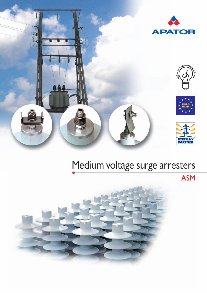
Medium voltage surge arrestersASM
Manufacturing range:SWITCHGEAR EQUIPMENTMETERING EQUIPMENT
VISION OF GRUPA APATORWe want our metering systems to help our customers with economical management of electricity, heat, water and gas consumption. We pursue to accuracy and flexibility of configuration of our metering systems, sophisticated technologies ofsettlement and read out of data supported by the latest achievements in telecommunication in order to allow our customers in very easy, cheap and saved method to settle the utilities. Our offer is enriched with services that guarantee our customers tosave time and money. Systems, applications and switchgear apparatus being in our offer help our customers with safe andreliable current making and breaking, providing and distributing of electricity. Safety operation of our switchgear equipment is the key to our success and complete satisfaction of our customers.
1
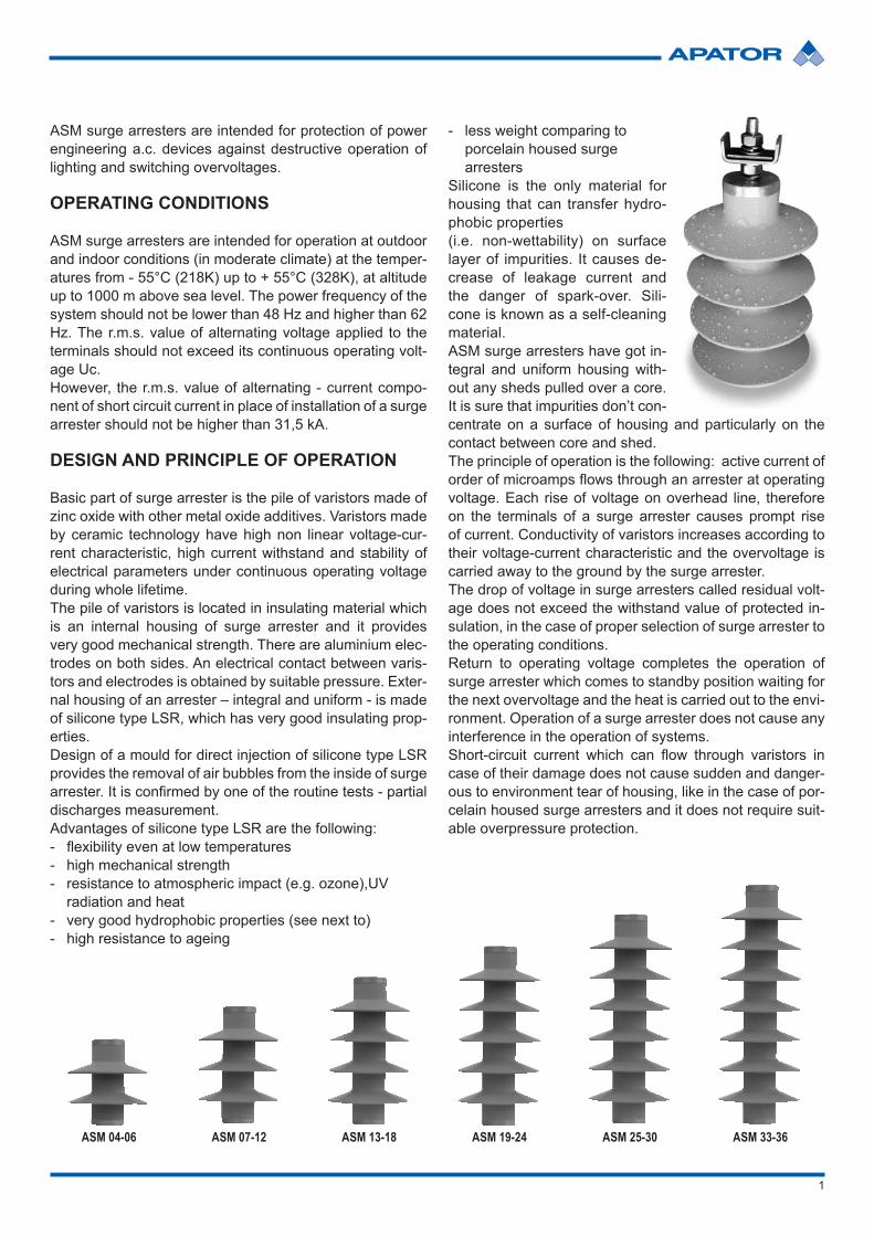
ASM 33-36ASM 04-06 ASM 07-12 ASM 13-18 ASM 19-24 ASM 25-30
ASM surge arresters are intended for protection of power engineering a.c. devices against destructive operation of lighting and switching overvoltages.
OPERATING CONDITIONS
ASM surge arresters are intended for operation at outdoor and indoor conditions (in moderate climate) at the temper-atures from - 55°C (218K) up to + 55°C (328K), at altitude up to 1000 m above sea level. The power frequency of the system should not be lower than 48 Hz and higher than 62 Hz. The r.m.s. value of alternating voltage applied to the terminals should not exceed its continuous operating volt-age Uc. However, the r.m.s. value of alternating - current compo-nent of short circuit current in place of installation of a surge arrester should not be higher than 31,5 kA.
DESIGN AND PRINCIPLE OF OPERATION
Basic part of surge arrester is the pile of varistors made of zinc oxide with other metal oxide additives. Varistors made by ceramic technology have high non linear voltage-cur-rent characteristic, high current withstand and stability of electrical parameters under continuous operating voltage during whole lifetime.The pile of varistors is located in insulating material which is an internal housing of surge arrester and it provides very good mechanical strength. There are aluminium elec-trodes on both sides. An electrical contact between varis-tors and electrodes is obtained by suitable pressure. Exter-nal housing of an arrester – integral and uniform - is made of silicone type LSR, which has very good insulating prop-erties.Design of a mould for direct injection of silicone type LSR provides the removal of air bubbles from the inside of surge arrester. It is confirmed by one of the routine tests - partialdischarges measurement.Advantages of silicone type LSR are the following: - flexibility even at low temperatures- high mechanical strength - resistance to atmospheric impact (e.g. ozone),UV
radiation and heat- very good hydrophobic properties (see next to)- high resistance to ageing
- less weight comparing to porcelain housed surge arresters
Silicone is the only material for housing that can transfer hydro-phobic properties (i.e. non-wettability) on surface layer of impurities. It causes de-crease of leakage current and the danger of spark-over. Sili-cone is known as a self-cleaning material. ASM surge arresters have got in-tegral and uniform housing with-out any sheds pulled over a core. It is sure that impurities don’t con-centrate on a surface of housing and particularly on the contact between core and shed.The principle of operation is the following: active current of order of microamps flows through an arrester at operatingvoltage. Each rise of voltage on overhead line, therefore on the terminals of a surge arrester causes prompt rise of current. Conductivity of varistors increases according to their voltage-current characteristic and the overvoltage is carried away to the ground by the surge arrester. The drop of voltage in surge arresters called residual volt-age does not exceed the withstand value of protected in-sulation, in the case of proper selection of surge arrester to the operating conditions.Return to operating voltage completes the operation of surge arrester which comes to standby position waiting for the next overvoltage and the heat is carried out to the envi-ronment. Operation of a surge arrester does not cause any interference in the operation of systems.Short-circuit current which can flow through varistors incase of their damage does not cause sudden and danger-ous to environment tear of housing, like in the case of por-celain housed surge arresters and it does not require suit-able overpressure protection.
2
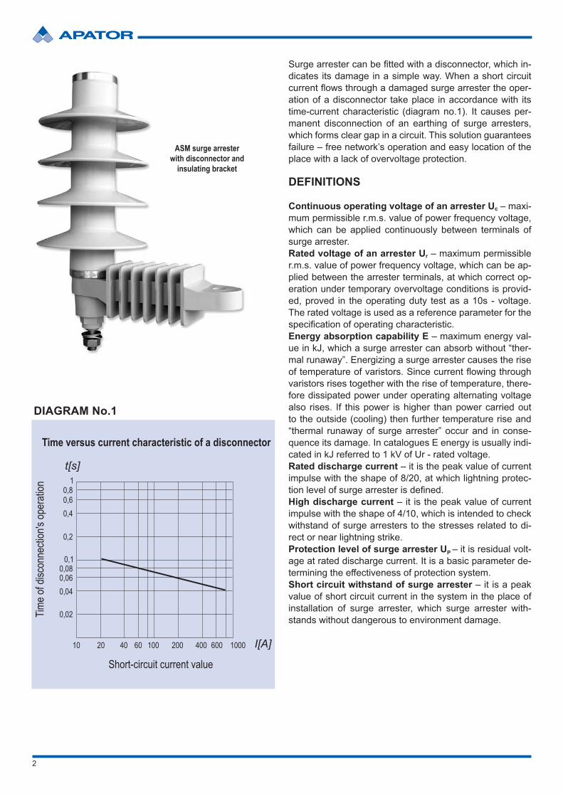
Surge arrester can be fitted with a disconnector, which in-dicates its damage in a simple way. When a short circuit current flows through a damaged surge arrester the oper-ation of a disconnector take place in accordance with its time-current characteristic (diagram no.1). It causes per-manent disconnection of an earthing of surge arresters, which forms clear gap in a circuit. This solution guarantees failure – free network’s operation and easy location of the place with a lack of overvoltage protection.
DEFINITIONS
Continuous operating voltage of an arrester Uc – maxi-mum permissible r.m.s. value of power frequency voltage, which can be applied continuously between terminals of surge arrester.Rated voltage of an arrester Ur – maximum permissible r.m.s. value of power frequency voltage, which can be ap-plied between the arrester terminals, at which correct op-eration under temporary overvoltage conditions is provid-ed, proved in the operating duty test as a 10s - voltage. The rated voltage is used as a reference parameter for the specification of operating characteristic.Energy absorption capability E – maximum energy val-ue in kJ, which a surge arrester can absorb without “ther-mal runaway”. Energizing a surge arrester causes the rise of temperature of varistors. Since current flowing throughvaristors rises together with the rise of temperature, there-fore dissipated power under operating alternating voltage also rises. If this power is higher than power carried out to the outside (cooling) then further temperature rise and “thermal runaway of surge arrester” occur and in conse-quence its damage. In catalogues E energy is usually indi-cated in kJ referred to 1 kV of Ur - rated voltage.Rated discharge current – it is the peak value of current impulse with the shape of 8/20, at which lightning protec-tion level of surge arrester is defined.High discharge current – it is the peak value of current impulse with the shape of 4/10, which is intended to check withstand of surge arresters to the stresses related to di-rect or near lightning strike. Protection level of surge arrester UP – it is residual volt-age at rated discharge current. It is a basic parameter de-termining the effectiveness of protection system.Short circuit withstand of surge arrester – it is a peak value of short circuit current in the system in the place of installation of surge arrester, which surge arrester with-stands without dangerous to environment damage.
DIAGRAM No.1
ASM surge arrester with disconnector and
insulating bracket
3
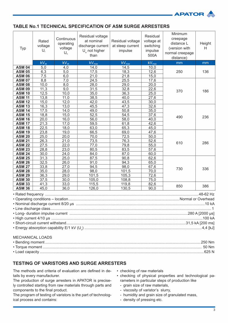
TABLE No.1 TECHNICAL SPECIFICATION OF ASM SURGE ARRESTERS
• Rated frequency ................................................................................................................................................48-62 Hz• Operating conditions – location ........................................................................................................Normal or Overhead• Nominal discharge current 8/20 µs .........................................................................................................................10 kA• Line discharge class ....................................................................................................................................................... 1• Long- duration impulse current ...............................................................................................................280 A [2000 µs]• High current 4/10 µs ..............................................................................................................................................100 kA • Short-circuit current withstand ................................................................................................................31,5 kA [200 ms]• Energy absorption capability E/1 kV (Uc) ..............................................................................................................4,4 [kJ]
MECHANICAL LOADS• Bending moment ..................................................................................................................................................250 Nm• Torque moment ..................................................................................................................................................... 50 Nm• Load capacity ..........................................................................................................................................................625 N
Typ
Rated voltage
Ur
Continuous operating voltage
Uc
Residual voltage at nominal
discharge current Uo not higher
than
Residual voltage at steep current
impulse
Residual voltage at switching impulse
500A
Minimum creepage distance L
(version with normal creepage
distance)
Height H
kVsk kVsk kVmax kVmax kVmax mm mmASM 04 5,0 4,0 14,0 14,5 10,0
250 136ASM 05 6,3 5,0 17,5 18,3 12,6ASM 06 7,5 6,0 21,0 21,8 15,0ASM 07 8,8 7,0 24,5 25,5 17,6
370 186
ASM 08 10,0 8,0 28,0 29,0 20,0ASM 09 11,3 9,0 31,5 32,8 22,6ASM 10 12,5 10,0 35,0 36,3 25,0ASM 11 13,8 11,0 38,5 40,0 27,6ASM 12 15,0 12,0 42,0 43,5 30,0ASM 13 16,3 13,0 45,5 47,3 32,6
490 236
ASM 14 17,5 14,0 49,0 50,8 35,0ASM 15 18,8 15,0 52,5 54,5 37,6ASM 16 20,0 16,0 56,0 58,0 40,0ASM 17 21,3 17,0 59,5 61,8 42,6ASM 18 22,5 18,0 63,0 65,3 45,0ASM 19 23,8 19,0 66,5 69,0 47,6
610 286
ASM 20 25,0 20,0 70,0 72,5 50,0ASM 21 26,3 21,0 73,5 76,3 52,6ASM 22 27,5 22,0 77,0 79,8 55,0ASM 23 28,8 23,0 80,5 83,5 57,6ASM 24 30,0 24,0 84,0 87,0 60,0ASM 25 31,3 25,0 87,5 90,8 62,6
730 336
ASM 26 32,5 26,0 91,0 94,3 65,0ASM 27 33,8 27,0 94,5 98,0 67,6ASM 28 35,0 28,0 98,0 101,5 70,0ASM 29 36,3 29,0 101,5 105,3 72,6ASM 30 37,5 30,0 105,0 108,8 75,0ASM 33 41,3 33,0 115,5 119,8 82,6 850 386ASM 36 45,0 36,0 126,0 130,5 90,0
TESTING OF VARISTORS AND SURGE ARRESTERSThe methods and criteria of evaluation are defined in de-tails by every manufacturer.The production of surge arresters in APATOR is precise-ly controlled starting from raw materials through parts and components to the final product.The program of testing of varistors is the part of technolog-ical process and contains:
• checking of raw materials• checking of physical properties and technological pa-
rameters in particular steps of production like- grain size of raw materials,- viscosity of varistor’s slurry,- humidity and grain size of granulated mass,- density of pressing etc.
4
Technology of production of varistors is composed of very precise mixing of all ingredients in water slurry, spray dry-ing of this slurry, cylindrical pressing of granulated mass and high temperature sintering of pressed pieces.
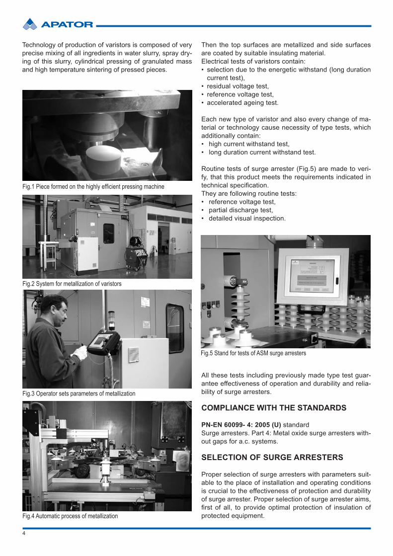
Fig.1 Piece formed on the highly efficient pressing machine
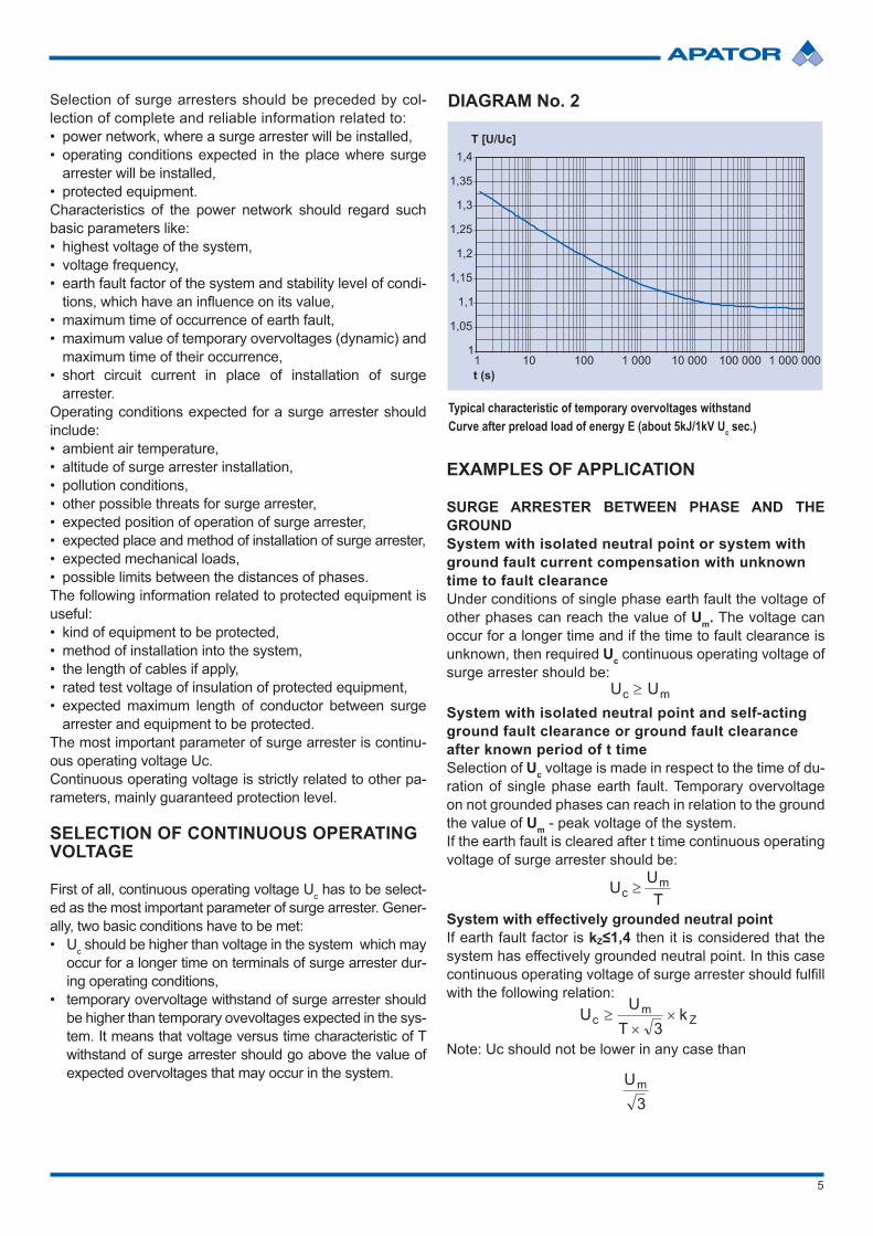
Fig.2 System for metallization of varistors
Fig.5 Stand for tests of ASM surge arresters
Fig.4 Automatic process of metallization
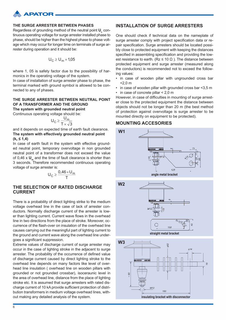
Fig.3 Operator sets parameters of metallization
Then the top surfaces are metallized and side surfaces are coated by suitable insulating material.Electrical tests of varistors contain:• selection due to the energetic withstand (long duration
current test),• residual voltage test,• reference voltage test,• accelerated ageing test.
Each new type of varistor and also every change of ma-terial or technology cause necessity of type tests, which additionally contain:• high current withstand test,• long duration current withstand test.
Routine tests of surge arrester (Fig.5) are made to veri-fy, that this product meets the requirements indicated in technical specification.They are following routine tests: • reference voltage test,• partial discharge test, • detailed visual inspection.
All these tests including previously made type test guar-antee effectiveness of operation and durability and relia-bility of surge arresters.
COMPLIANCE WITH THE STANDARDS
PN-EN 60099- 4: 2005 (U) standard Surge arresters. Part 4: Metal oxide surge arresters with-out gaps for a.c. systems.
SELECTION OF SURGE ARRESTERS
Proper selection of surge arresters with parameters suit-able to the place of installation and operating conditions is crucial to the effectiveness of protection and durability of surge arrester. Proper selection of surge arrester aims, first of all, to provide optimal protection of insulation ofprotected equipment.
5
Selection of surge arresters should be preceded by col-lection of complete and reliable information related to:• power network, where a surge arrester will be installed,• operating conditions expected in the place where surge
arrester will be installed,• protected equipment.Characteristics of the power network should regard such basic parameters like:• highest voltage of the system,• voltage frequency,• earth fault factor of the system and stability level of condi-
tions, which have an influence on its value,• maximum time of occurrence of earth fault,• maximum value of temporary overvoltages (dynamic) and
maximum time of their occurrence,• short circuit current in place of installation of surge
arrester.Operating conditions expected for a surge arrester should include:• ambient air temperature,• altitude of surge arrester installation,• pollution conditions,• other possible threats for surge arrester,• expected position of operation of surge arrester,• expected place and method of installation of surge arrester,• expected mechanical loads,• possible limits between the distances of phases.The following information related to protected equipment is useful:• kind of equipment to be protected,• method of installation into the system,• the length of cables if apply,• rated test voltage of insulation of protected equipment,• expected maximum length of conductor between surge
arrester and equipment to be protected.The most important parameter of surge arrester is continu-ous operating voltage Uc.Continuous operating voltage is strictly related to other pa-rameters, mainly guaranteed protection level.
SELECTION OF CONTINUOUS OPERATING VOLTAGE
First of all, continuous operating voltage Uc has to be select-ed as the most important parameter of surge arrester. Gener-ally, two basic conditions have to be met:• Uc should be higher than voltage in the system which may
occur for a longer time on terminals of surge arrester dur-ing operating conditions,
• temporary overvoltage withstand of surge arrester should be higher than temporary ovevoltages expected in the sys-tem. It means that voltage versus time characteristic of T withstand of surge arrester should go above the value of expected overvoltages that may occur in the system.
EXAMPLES OF APPLICATION
SURGE ARRESTER BETWEEN PHASE AND THE GROUND System with isolated neutral point or system with ground fault current compensation with unknown time to fault clearanceUnder conditions of single phase earth fault the voltage of other phases can reach the value of Um. The voltage can occur for a longer time and if the time to fault clearance is unknown, then required Uc continuous operating voltage of surge arrester should be:
System with isolated neutral point and self-acting ground fault clearance or ground fault clearance after known period of t timeSelection of Uc voltage is made in respect to the time of du-ration of single phase earth fault. Temporary overvoltage on not grounded phases can reach in relation to the ground the value of Um - peak voltage of the system.If the earth fault is cleared after t time continuous operating voltage of surge arrester should be:
System with effectively grounded neutral pointIf earth fault factor is kZ≤1,4 then it is considered that the system has effectively grounded neutral point. In this case continuous operating voltage of surge arrester should fulfillwith the following relation:
Note: Uc should not be lower in any case than
Typical characteristic of temporary overvoltages withstand Curve after preload load of energy E (about 5kJ/1kV Uc sec.)
DIAGRAM No. 2
6
THE SURGE ARRESTER BETWEEN PHASESRegardless of grounding method of the neutral point Uc con-tinuous operating voltage for surge arrester installed phase to phase, should be higher than the highest phase to phase volt-age which may occur for longer time on terminals of surge ar-rester during operation and it should be:
where 1, 05 is safety factor due to the possibility of har-monics in the operating voltage of the system.In case of installation of surge arrester phase to phase, the terminal marked with ground symbol is allowed to be con-nected to any of phases.
THE SURGE ARRESTER BETWEEN NEUTRAL POINT OF A TRANSFORMER AND THE GROUNDThe system with grounded neutral pointContinuous operating voltage should be:
and it depends on expected time of earth fault clearance.The system with effectively grounded neutral point (kz ≤ 1,4)In case of earth fault in the system with effective ground-ed neutral point, temporary overvoltage in non grounded neutral point of a transformer does not exceed the value of 0,46 x Um and the time of fault clearance is shorter than 3 seconds. Therefore recommended continuous operating voltage of surge arrester is:
THE SELECTION OF RATED DISCHARGE CURRENT
There is a probability of direct lighting strike to the medium voltage overhead line in the case of lack of arrester con-ductors. Normally discharge current of the arrester is low-er than lighting current. Current wave flows in the overheadline in two directions from the place of stroke. Moreover, oc-currence of the flash-over on insulation of the overhead linecauses carrying out the meaningful part of lighting current to the ground and current wave along the overhead line under-goes a significant suppression.Extreme values of discharge current of surge arrester may occur in the case of lighting stroke in the adjacent to surge arrester. The probability of the occurrence of defined valueof discharge current caused by direct lighting stroke to the overhead line depends on many factors like level of over-head line insulation ( overhead line on wooden pillars with grounded or not grounded crossbar), isoceraunic level in the area of overhead line, distance from the place of lighting stroke etc. It is assumed that surge arresters with rated dis-charge current of 10 kA provide sufficient protection of distri-bution transformers in medium voltage overhead lines, with-out making any detailed analysis of the system.
MOUNTING ACCESORIES
W1
angle metal bracket
W2
straight metal bracket
W3
insulating bracket with disconnector
INSTALLATION OF SURGE ARRESTERS
One should check if technical data on the nameplate of surge arrester comply with project specification data or re-pair specification. Surge arresters should be located possi-bly close to protected equipment with keeping the distances specified in assembling specification and providing the low-est resistance to earth. (Rz ≤ 10 Ω ). The distance between protected equipment and surge arrester (measured along the conductors) is recommended not to exceed the follow-ing values:• in case of wooden pillar with ungrounded cross bar
<2,0 m• in case of wooden pillar with grounded cross bar <3,5 m• in case of concrete pillar < 2,0 mHowever, in case of difficulties in mounting of surge arrest-er close to the protected equipment the distance between objects should not be longer than 20 m (the best method of protection against overvoltage is surge arrester to be mounted directly on equipment to be protected).
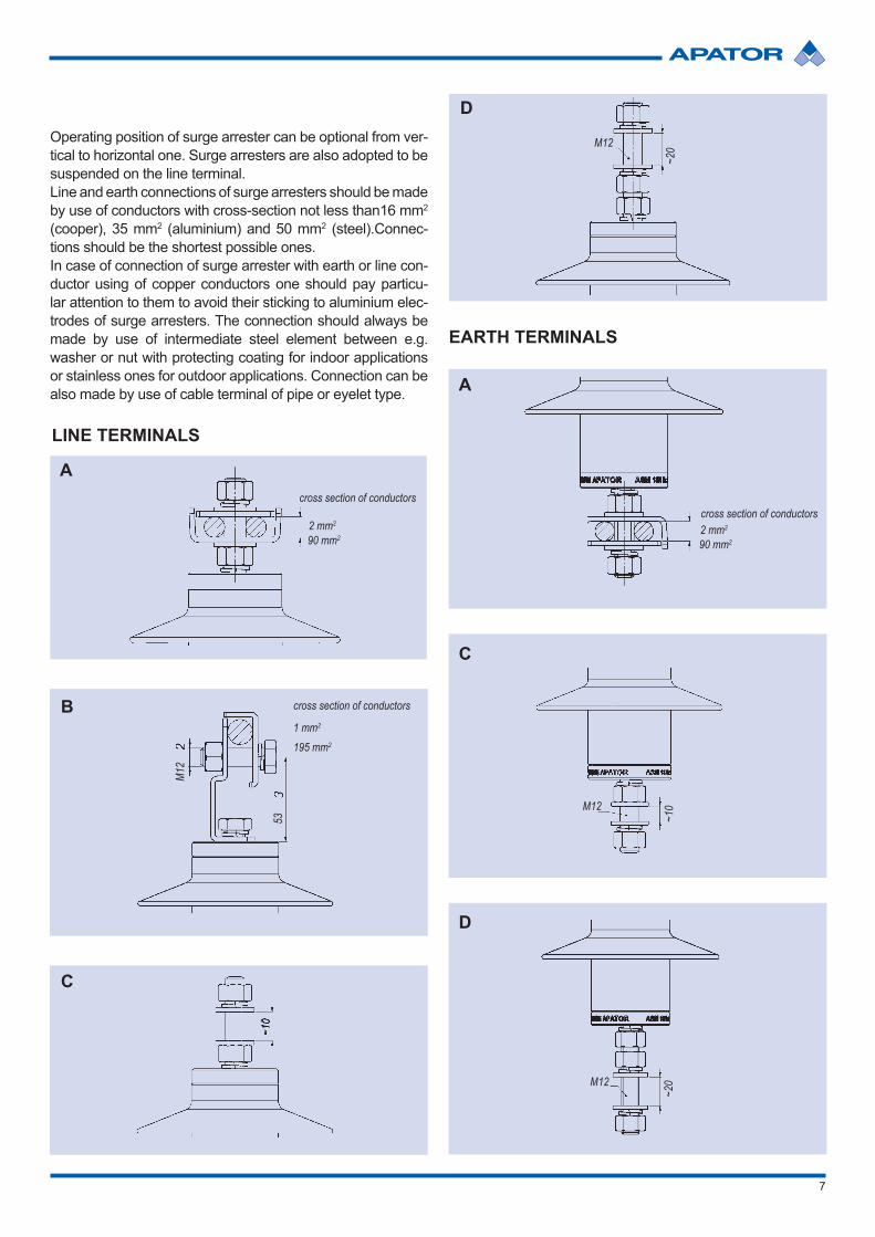
7
D
M12
~20
C
M12
~10
EARTH TERMINALS
D
~20M12
C
~10
B
53
M12
1 mm2
195 mm2
cross section of conductors
LINE TERMINALS
A
2 mm2
cross section of conductors
90 mm2
A
2 mm2
cross section of conductors
90 mm2
Operating position of surge arrester can be optional from ver-tical to horizontal one. Surge arresters are also adopted to be suspended on the line terminal. Line and earth connections of surge arresters should be made by use of conductors with cross-section not less than16 mm2 (cooper), 35 mm2 (aluminium) and 50 mm2 (steel).Connec-tions should be the shortest possible ones. In case of connection of surge arrester with earth or line con-ductor using of copper conductors one should pay particu-lar attention to them to avoid their sticking to aluminium elec-trodes of surge arresters. The connection should always be made by use of intermediate steel element between e.g. washer or nut with protecting coating for indoor applications or stainless ones for outdoor applications. Connection can be also made by use of cable terminal of pipe or eyelet type.
8
TABLE No. 2 MOUNTING DATA
Type
of s
urge
arr
este
r
Con
tinuo
us o
pera
ting
volta
ge [V
]
Rat
ed v
olta
ge [V
]
Minimal distance
Bet
wee
n th
e ax
is
of s
urge
arr
este
r an
d “a
” ear
thed
st
ruct
ure
Bet
wee
n ax
es o
f su
rge
arre
ster
s an
d “b
” adj
acen
t ph
ases
mm mmASM 06 6,0 7,5 106 141ASM 12 12,0 15,0 172 206ASM 18 18,0 22,5 239 271ASM 24 24,0 30,0 306 336ASM 30 30,0 37,5 370 401ASM 36 36,0 45,0 436 466
a b b
Surge arresters with standard fittings can be mounted di-rectly to grounded metal construction and in case of non-metal one by use of grounding metal bar with the suitable cross-section and width not less than 20 mm.In case when additional fittings are delivered as not in-stalled it should be properly installed to the surge arrester.Surge arrester can be also used as auxiliary post-off insu-lator e.g. on transformer pillar stations where such function is usually played by ceramic insulator providing safety dis-tance between steel structure elements and line conduc-tors. Application of surge arrester for that function allows eliminating intermediate insulators and assures avoiding using indirect isolators and providing close distance of the arrester to the protected equipment.
NOTE:Regulations regarding the performance of power engineer-ing equipment in appropriate country should be respected during operation of surge arresters.In case of application of minimal distances in the place of in-stallation of surge arrester local regulations should be also respected.
During mounting of surge arresters one should draw his at-tention to the torque moment to be Ms ≤ 50 Nm and bend-ing moment to be Mg≤ 250 Nm. It also regards to operating conditions. In case of keeping for the above conditions – operating position for ASM surge arresters can be optional from vertical to horizontal one.
H
φ135
M12
φ54
M12

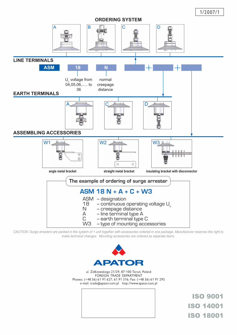
1/2007/1
A B C
C
ASSEMBLING ACCESSORIES
ORDERING SYSTEM
LINE TERMINALS
EARTH TERMINALS
normal creepage distance
Uc voltage from 04,05,06,..... to
36
CAUTION: Surge arresters are packed in the system of 1 unit together with accessories ordered in one package. Manufacturer reserves the right to make technical changes. Mounting accessories are ordered as separate items.
The example of ordering of surge arrester
ASM
ASM 18 N + A + C + W3ASM – designation18 – continuous operating voltage UcN – creepage distanceA – line terminal type AC – earth terminal type CW3 – type of mounting accessories
18 N
D
D
W1
A
W3W2
angle metal bracket straight metal bracket insulating bracket with disconnector
ISO 9001ISO 14001ISO 18001
ul. Żółkiewskiego 21/29, 87-100 Toruń, PolandFOREIGN TRADE DEPARTMENT
Phones: (+48 56) 61 91 627; 61 91 316; Fax: (+48 56) 61 91 295e-mail: [email protected] http://www.apator.com.pl