Embed Size (px)
Citation preview

Medium Voltage Products
V-ContactMedium voltage vacuum contactors


3
9
1
2
3
39
43
4
5
59
6
31
67
7
DESCRIPTION
CONTACTOR SELECTION AND ORDERING 2
UNIMOTOR ENCLOSURE SELECTION AND ORDERING
POWERCUBE UNITS
SPECIFIC PRODUCT CHARACTERISTICS
OVERALL DIMENSIONS
ELECTRIC CIRCUIT DIAGRAM

2
3
1
General 4
Available versions 5
Fields of application 6
Quality Assurance System 6
Environmental Management System 6
Health and Safety Management System 6
Test laboratory 6
Compliance with Standards 6
Approvals 6
Operating characteristics 6
Main technical characteristics 6
Electrical life 6
Interruption principle 7
Technical documentation 8
DESCRIPTION

4
Fixed.
DESCRIPTION
GeneralThe MV V-Contact series are apparatus suitablefor operating in a.c. They are normally used tocontrol users requiring a high number of hourlyoperations. The contactors basically consist of amoulded resin monobloc containing the vacuuminterrupters, the moving parts, the electromagnet,the multi-voltage control feeder and the auxiliaryaccessories.The monobloc is the support for assembly of thefuse-holder frame. Closing of main contacts iscarried out by means of the control electromagnet.Opening is carried out by means of a specialcounteracting spring.Construction is compact and sturdy and ensuresvery long electrical and mechanical life, evenwithout maintenance.The accessories allow the contactor to be easilypersonalised and facilitate stock management.The V-Contact contactors are interchangeable withthe withdrawable VRC series contactors andguarantee the same performances are covered(Check interchangeability of the electric diagram).Retrofit kit for the enclosure, available on request,is needed for the UniMotor version.
Withdrawable for UniMotor enclosure.
Withdrawable for CBE/PowerCube enclosure.

5
1
Available versionsThe V-Contact are fitted with electrical latching asstandard and are available for rated voltages of7.2 kV (V7) and 12 kV (V12), in the followingversions:– fixed (which can be supplied, on request, with a
fuse-holder frame)– single-pole fixed (for earthing the star centre of the transformers - application of the fuse-holder
frame is not provided)– withdrawable for CBE enclosure and
PowerCube unit– withdrawable for UniMotor enclosure and
switchgear– withdrawable for ZS1 and UniGear ZS1 type
switchgear.
The withdrawable versions consist of acontactor fitted with a withdrawable truck andpower circuit isolating contacts.
The fuse-holder frame is standard for withdraw-able contactors, on request for fixed contactorsand is normally preset for installation of fuses withdimensions, average type of striker and electricalcharacteristics in compliance with CENELEC EN60282-1 (94) Standards.
The contactors can be coupled with the followingfuses:– V7 with fuses from 6 A to 450 A (up to 315 A for motor protection; up to 450 A for capacitor bank protection)– V12 with fuses from 6 A to 200 A.
PowerCube series unit.
UniMotor series enclosure.
The fuse-holder frames are fitted with an auto-matic opening device when even a single fuseblows. The same device also prevents closure ofthe contactor in the case when even a single fuseis missing.

6
DESCRIPTION
Fields of applicationThe V-Contact series of contactors are used forcontrolling electrical apparatus in industry, in theservice sector, in the marine sector, etc. Thanks tothe vacuum interrupter breaking technique, thecontactors can operate in particularly difficultenvironments. They are suitable for control andprotection of motors, transformers, power factorcorrection banks, switching systems, etc.Fitted with suitable fuses, they can be used incircuits with fault levels up to 1000 MVA.
Compliance with StandardsThe V-Contact contactors comply with the Stand-ards of the major industrialised countries and inparticular with:– IEC 60470 (2000) and IEC 632-1 (1978) for the
contactor– IEC 282-1 / CENELEC EN 60282-1 (1994) for
the fuses– IEC 298 for the enclosures.
ApprovalsThe contactors are approved by RINA, LL.RR. andDNV shipping registers.
Operating characteristics• Ambient temperature: – 5 °C ... + 40 °C• Relative humidity: < 95 %• Altitude: < 1000 m a.s.l.
For other conditions, please contact us.
Main technical characteristics• Chopping current value ≤ 0.5 A• Maintenance-free• High number of operations• Long electrical and mechanical life• Direct checking of contact wear• Remote control• Possibility of integration in computerised control
systems• Suitable for installation in prefabricated substa-
tions and switchgear• Multi-voltage feeder.
Electrical lifeThe electrical life of V-Contact contactors isdefined in category AC3 with 100,000 operations(closing-opening), interrupted current 400 A,closing current 2.4 kA, and cosϕ = 0.35.
Quality Assurance SystemCertified by an external independent organizationas complying with ISO 9001 Standards.
Environmental Management SystemCertified by an external independent organizationas complying with ISO 14001 Standards.
Health and Safety Management SystemCertified by an external independent organizationas complying with OHSAS 18001 Standards.
Test laboratoryAccredited by an external independent organiza-tion as complying with UNI CEI EN ISO/IEC 17025Standards.
Fixed version V-Contact.

7
1
2
2
4
13
5
5
6
7
4 5321
1 Monobloc2 Vacuum interrupters3 Terminals4 Support5 Feeder6 Auxiliary contacts7 Closing electromagnets
Interruption principleThe main contacts of the contactor operate insidethe vacuum interrupters (the level of vacuum isextremely high: 13 x 10-5 Pa).On opening, there is rapid separation of the fixedand moving contacts in each contactor interrupter.Overheating of the contacts, generated at themoment they separate, causes formation ofmetallic vapours which allow the electric arc to besustained up to the first zero current passage. Onpassage of zero current, cooling of the metallicvapours allows recovery of high dielectric rigidityable to withstand high values of return voltage. Inthe version for motor switching, the value of thechopped current is less than 0.5 A with extremelylimited overvoltages.
Schematic cross-section of the vacuum interrupter.
1 Ceramic housing2 Seal diaphragm3 Metal screen4 Moving contact5 Fixed contact

8
1
I1
V1
I2
V2
I3
V3
Iem
C
I1
V1
I2
V2
I3
V3
Iem
O
DESCRIPTION
Oscillogram of short-circuit test Travel
Contactor: V-Contact V7Voltage: 7.2 kVCurrent: 4000 AV
1 - V
2 - V
3: R-S-T phase
voltageI1 - I
2 - I
3: R-S-T phase
currentIem: Control
electromagnetcurrent
C: Circuit closureO: Circuit interrup-
tion
Oscillogram of short-circuit test Travel
Travel
Travel
Technical documentationFor more in-depth knowledge of the technical andapplication aspects of the V-Contact series contactors,the following technical catalogues are available:– UniGear switchgear Code 1VCP000138– UniMotor switchgear Code 1VCP000079

9
2
General characteristics 10
Standard fittings 11
Contactor ordering codes 12
Accessory ordering codes 13
CONTACTOR SELECTION AND ORDERING

10
CONTACTOR SELECTION AND ORDERING
General characteristics
Rated voltage
Rated insulation voltage
Withstand voltage at 50 Hz
Impulse withstand voltage (1)
Rated frequency
Rated service current (2)
Short-time withstand current
Short-time withstand current for 1 s
Short-time withstand current for 30 s
Rated peak current
Rated short-circuit time (tk)
Breaking capacity up to (Isc)
Making capacity under short-circuit up to (Ima)
Rated values
Contactor with electrical latching (4)
Contactor with mechanical latching (5)
Rated maximum overcurrent wisthand for 1/2 period (peak value)
Rated load and overload characteristics in category of use:
(Category AC4) 100 closing operations
(Category AC4) 25 opening operations
Rated voltage of the operating devices and auxiliary circuits
Feeder type 1 (24 ... 60 DC)
Feeder type 2 (100 ... 250 AC-DC)
Normal current
Electrical life (category AC3) (6)
Electrical life at rated current (electrical latching)
Coordination with protection devices against short-circuit
Apparatus wear classification (type)
Breaking capacity under short-circuit (single cycle O-3min-CO-3min-CO)
Making capacity under short-circuit (single cycle O-3min-CO-3min-CO)
Limit above which the fuse blows (10)
Values and characteristics V-Contact V7Reference to IEC60470 Standard
Contactor
3.4.105
Starter
3.4.110
Combined withfuses
3.4.110.9
Ur [kV]
Ud (1 min) [kV]
Up [kVp]
fr [Hz]
Ie [A]
Ik [A]
Ik [A]
Ip [kA peak ]
tk [s]
Isc [kA]
Ima [kA]
[op./hour]
[op./hour]
[kA]
[A]
[A]
Ith [A]
[A]
[A peak]
[A]
4.1
4.2
4.2
4.3
4.101
4.5
4.5
4.6
4.7
4.107
4.107
4.102
4.102
–
4.103, 4.104
4.103, 4.104
4.8, 4.9
4.4.101
4.106
4.106
4.107
4.107.3
4.107, 6.104
4.107, 6.104
4.107.2
7.2
20
60
50-60
400
6000
2500
15
1
–
–
900
300
55
4000
4000
400
100,000
1,000,000
(7)
C
6000
15000
–
7.2
20
60
50-60
400
6000
2500
15
1
–
–
900
300
–
4000
4000
400
–
–
(7)
C
6000
15000
–
7.2
20
60
50-60
400
6000
2500
15
1
50 (3)
50 (3)
900
300
–
4000
4000
(2)
–
–
(7)
C
–
–
5000
2.2/2.5
1000
1100
1000
3.3
1500
1600
1500
3.6/5
1500
2000
1500
6,2/7,2
3000
4000
3000
250
8
2.5
15 ... 25
15 ... 20
40 ... 80
25/40
55
45
398 x 365 x 350
636 x 532 x 600
508 x 383 x 768
Ultimate performances for (at a voltage of):
- motors
- transformers
- capacitors
Ultimate performances for back-to-back capacitor banks
- rated current
- maximum transient capacitor bank switching-in current
- maximum transient capacitor bank switching-in frequency
Opening time with electrical latching (8)
Opening time with mechanical latching (8)
Closing time (8)
Weights fixed / fixed with fuse-holders (9)
withdrawable for CBE, CBF, PowerCube, UniGear ZS1 type (9)
withdrawable for UniMotor (9)
Overall dimensions
fixed / fixed with fuse-holders
withdrawable for CBE, CBF, PowerCube, UniGear ZS1 type
withdrawable for UniMotor
Tropicalisation
[kV]
[kW]
[kVA]
[kVAr]
[A]
[kA]
[kHz]
[ms]
[ms]
[ms]
[kg]
[kg]
[kg]
(HxLxD) [mm]
(HxLxD) [mm]
(HxLxD) [mm]
IEC 721-2-1

11
2
Standard fittingsAs standard, the contactors are fitted with:– operating mechanism with electrical latching– mechanical open/closed signalling– six pairs of open/closed signalling contacts (six
break contacts plus six make contacts)– multi-voltage feeder (type 1: 24-60 V d.c. for
V-Contact V7 only; type 2: 100-250 V d.c./a.c.50-60 Hz)
– basic cabling with socket– cabled plug with 3 m long cord.And, moreover, only for withdrawable contactor:– plug connector– fuse-holders, with electric release device preset
for installation of fuses in compliance with DINStandards with cartridge length e = 442 mm, orBS Standards with cartridge length L = 553 mm.For shorter fuses, special adaptation kits mustbe ordered (see accessories)
– tool for removing the DIN type fuses– mechanical release device for fuse intervention.
(1) 75 kV BIL only for fixed V12 contactor.For the withdrawable versions for UniGearor PowerCube switchgear or for PowerCubeor CBE enclosures, the 75 kV BIL insulationlevel is available on request.
(2) Rated service current defined for fixedcontactors; for the contactors coordinatedwith fuses, the limits are as follows:- 7.2 kV in ABB 250 A units with maximum
fuse size (315 A)- 12 kV in ABB 160A units with maximum
fuse size (200 A).(3) For the breaking capacity of the coordi-
nated fuses, please see the followingpages.
(4) Mechanical life (opening/closing cycles)1,000,000.
(5) Mechanical life (opening/closing cycles)250,000.
(6) Electrical life which can be obtainedfollowing the programmed maintenance planin the product instruction manual.
(7) Coordination is guaranteed with the types offuses indicated on the following pages.
(8) Lower and upper limits.(9) Fuses excluded (the maximum fuse size
weighs 5.5 Kg).(10) This is the current value determined by the
intersection of the time-current trip curve oftwo protection devices; in this case thefuse and any thermal protection relay.
(11) Application of overvoltage surge arrestersor RC filters is necessary.
Fixed version V-Contact.
12
28
60
50-60
400
6000
2500
15
1
–
–
900
300
55
4000
4000
–
400
100,000
1,000,000
(7)C
4000
8000
–
12
28
60
50-60
400
6000
2500
15
1
–
–
900
300
–
4000
4000
–
400
–
–
(7)
C
4000
8000
–
12
28
60
50-60
400
6000
2500
15
1
50 (3)
50 (3)
900
300
–
4000
4000
–
(2)
–
–
(7)
C
–
–
5000
230
8
2.5
15 ... 25
15 ... 20
40 ... 80
25/40
55
45
398 x 365 x 350
636 x 532 x 600
508 x 383 x 768
V-Contact V12Contactor
3.4.105
Starter
3.4.110
Combined withfuses
3.4.110.9
12
5000
5000
4800 (11)

12
V-ContactV-Contact
CONTACTOR SELECTION AND ORDERING
Contactor ordering codes
Fixed with electrical latching
U [kV] In [A] Feeder type V-Contact 1VCF
7,2 400 1 (24 ... 60 V –) V7 304111R0100
2 (100 ... 250 V – / ~) V7 304111R0200
12 400 2 (100 ... 250 V – / ~) V12 304112R0200
Withdrawable with electrical latching for CBF11, CBE11
U [kV] In [A] Feeder type V-Contact 1VCF
7,2 400 1 (24 ... 60 V –) V7/C 304161R0100
2 (100 ... 250 V – / ~) V7/C 304161R0200
12 400 2 (100 ... 250 V – / ~) V12/C 304162R0200
Fixed single-pole with electrical latching (transformer star centre earthing)
U [kV] In [A] Feeder type V-Contact 1VCF
7,2 400 1 (24 ... 60 V –) VU7 304211R0100
2 (100 ... 250 V – / ~) VU7 304211R0200
12 400 2 (100 ... 250 V – / ~) VU12 304212R0200
Withdrawable with electrical latching for ZS1 switchgear
U [kV] In [A] Feeder type V-Contact 1VCF
7,2 400 1 (24 ... 60 V –) V7/Z 304151R0100
2 (100 ... 250 V – / ~) V7/Z 304151R0200
12 400 2 (100 ... 250 V – / ~) V12/Z 304152R0200
Withdrawable with electrical latching for UniGear ZS1 type switchgear
U [kV] In [A] Feeder type V-Contact 1VCF
7,2 400 1 (24 ... 60 V –) V7/P 304181R0100
2 (100 ... 250 V – / ~) V7/P 304181R0200
12 400 2 (100 ... 250 V – / ~) V12/P 304182R0200
Withdrawable with electrical latching for PowerCube modules
U [kV] In [A] Feeder type V-Contact 1VCF
7,2 400 1 (24 ... 60 V –) V7/W 304171R0100
2 (100 ... 250 V – / ~) V7/W 304171R0200
12 400 2 (100 ... 250 V – / ~) V12/W 304172R0200

13
2
1
2
3
5
6
10
4
V-ContactV-Contact
Withdrawable with electrical latching UniMotor enclosures/switchgear
U [kV] In [A] Feeder type V-Contact 1VCF
7.2 400 1 (24 ... 60 V –) V7/UN 304131R0100
2 (100 ... 250 V – / ~) V7/UN 304131R0200
12 400 2 (100 ... 250 V – / ~) V12/UN 304132R0200
Accessory ordering codes
Accessories which can be combined for fixed contactor
Standard fittings– operating mechanism with electrical latching– mechanical open/closed signalling– six pairs of open/closed signalling contacts
(six break contacts plus six make contacts)– multi-voltage feeder– basic cabling with socket– plug with cord 3 m long.
N.B.: the interlock between two superimposedcontactors has to be made electrically. It allows theoperations of the two contactors to be interlockedwith each other and is suitable, for example, for usein circuits with automatic commutation.
(*) The voltage transformer receives the powersupply from the upper poles of the contactor.
Voltage transformerfor self-supply (*)
Fuse-holder and fuseintervention releasedevice. 108 mm polecentre distance, onlyup to 7.2 kV.
Operation counter
Mechanical latching
Shunt opening release
Opening pushbutton
Fuses
Fuse adapter
Application of accessories
Customer ABB
Alternativeconnectionsto the fuses

14
2
3
4
5
6
7
8
9
10
CONTACTOR SELECTION AND ORDERING
Standard fittings– operating mechanism with electrical latching– mechanical open/closed signalling– six pairs of open/closed signalling contacts (six break contacts plus six make
contacts)– multi-voltage feeder– basic cabling with socket– plug connector– fuse-holder, with electric release device preset for installation of fuses in compliance
with DIN Standards with cartridge length e = 442 mm or BS Standards with car-tridge length L = 553 mm.For shorter fuses, special adaptation kits must be ordered (see accessories)
– tool for removing DIN type fuses– mechanical release device for fuse intervention.
N.B.: the interlock between two superimposed contactors has to be make electri-cally. It allows the operations of the two contactors to be interlocked with each otherand is suitable, for example, for use in circuits with automatic commutation.
Connections(alternative to thefuses)
Operation counter
Position contacts
Locking magnet
Interlock with door(V/C only)
Voltage transformer (*)
Fuse adapter
Mechanical latching
Shunt opening release
Opening pushbutton
Fuses
Customer ABB
Accessories which can be combined for withdrawable contactor - CBE and ZS1
Application ofaccessories
(*) The voltage trans-former receives thepower supply from theupper poles of the con-tactor.

15
2
2
3
4
5
6
7
10
12
Standard fittings– operating mechanism with electrical latching– mechanical open/closed signalling– six pairs of open/closed signalling contacts (six break contacts plus six make
contacts)– multi-voltage feeder– basic cabling with socket– plug connector– fuse-holder, with electric release device preset for installation of fuses in
compliance with DIN Standards with cartridge length e = 442 mm or BSStandards with cartridge length L = 553 mm. For shorter fuses, specialadaptation kits must be ordered (see accessories)
– tool for removing DIN type fuses– mechanical release device for fuse intervention.– anti-racking-in lock for different rated currents. Includes the locking magnet
on the truck.
Connections(alternativeto the fuses)
Operation counter
Position contacts
Voltagetransformer (*)
Insulating barrier (**)
Fuse adapter
Mechanical latching
Shunt opening release
Opening pushbutton
Fuses
Accessories which can be combined for withdrawable contactor - UniGear ZS1 type
(*) The voltage trans-former receives thepower supply from theupper poles of the con-tactor.
(**) The insulating barrier ismounted in the switch-gear to guarantee theimpulse withstand volt-age up to 75 kV, forV12/P contactors.
Customer ABB
Application ofaccessories

16
2
3
4
5
6
11
10
Accessories which can be combined for withdrawable contactor - PowerCube
Standard fittings– operating mechanism with electrical latching– mechanical open/closed signalling– six pairs of open/closed signalling contacts (six break contacts plus six
make contacts)– multi-voltage feeder– basic cabling with socket– plug connector– fuse-holder, with electric release device preset for installation of fuses in
compliance with DIN Standards with cartridge length e = 442 mm or BSStandards with cartridge length L = 553 mm. For shorter fuses, specialadaptation kits must be ordered (see accessories)
– tool for removing DIN type fuses– mechanical release device for fuse intervention– anti-racking-in lock for different rated currents. Includes the
locking magnet on the truck.
Fuses
Connections(alternativeto the fuses)
Operation counter
Voltage transformer (*)
Fuse adapter
Mechanical latching
Shunt opening release
Opening pushbutton
Customer ABB
Application ofaccessories
(*) The voltage transformerreceives the power sup-ply from the upper polesof the contactor.
Isolating lock
CONTACTOR SELECTION AND ORDERING

17
2
2
3
4
5
6
10
Accessories which can be combined for withdrawable contactor - UniMotor enclosure and switchgear
Fuses
Connections(alternative to thefuses)
Operation counter
Voltage transformer (*)
Fuse adapter
Mechanical latching
Shunt opening release
Opening pushbutton
Standard fittings– operating mechanism with electrical latching– mechanical open/closed signalling– six pairs of open/closed signalling contacts (six break contacts plus six make
contacts)– multi-voltage feeder– plug connector– fuse-holder, with electric release device preset for installation of fuses in compliance
with DIN Standards with cartridge length e = 442 mm or BS Standards with car-tridge length L = 553 mm.For shorter fuses, special adaptation kits must be ordered (see accessories)
– tool for removing DIN type fuses– mechanical release device for fuse intervention.
N.B.: the interlock between two superimposed contactors has to be make electrically.It allows the operations of the two contactors to be interlocked with each other and issuitable, for example, for use in circuits with automatic commutation.
Customer ABB
Application ofaccessories
(*) The voltage transformerreceives the power sup-ply from the upper polesof the contactor.

18
1
CONTACTOR SELECTION AND ORDERING
Fuse-holder for fixed contactor and electric release device for fuse intervention
This consists of a set of three supports which allowthe medium voltage circuit protection fuses to behoused.It is normally prepared for installation of fuses incompliance with DIN Standards with dimensione = 442 mm, or BS Standard fuses with dimensionL = 553 mm. For shorter fuses, special adaptersmust be applied (see accessory 3).The fuse-holders are always combined with theelectric release device for fuse intervention.
This device makes the contactor open on interven-tion of one or more fuses and prevents its closurewhen even a single fuse is missing.The fuses must have the dimensions and strikerof average type according to DIN 43625 andBS 2692 (1975) Standards.The electrical characteristics must comply withIEC 282-1 (1974) Standards.
V7; V12
Kit Fuses Pole centre distance 1VCF
1A DIN 108 mm (V7) 309400R02511B BS 108 mm (V7) 309400R02521C DIN 150 mm (V7) 309400R02531D BS 150 mm (V7) 309400R02541E DIN 150 mm (V12) 309400R02551F BS 150 mm (V12) 309400R0256
V-Contact in fixed versionwith fuse-holder.

19
22
2
The fuses are positioned in special supports to beconnected in series between the contactor and theuser. The supports can house fuses in compliancewith DIN or BS Standards.Selection of the fuses must be made according tothe characteristics of the user to be protected.
For fuse selection, see “Service conditionsdepending on the load” - chapter 5.The tables below show the fuse ordering codes.Each code identifies a single fuse.
ABB CMF type DIN Standard fuses for motor protection
V7; V12; V7/C; V12/C; V7/Z; V12/Z; V7/P; V12/P; V7/W; V12/W; V7/UN; V12/UN
Kit Un [kV] In [A] e [mm] Adapter 1VCF kA (*)
2A 3.6 100 292 3B 309401R0101 502A 3.6 160 292 3B 309401R0102 502A 3.6 200 292 3B 309401R0103 502A 3.6 250 292 3B 309401R0104 502A 3.6 315 292 3B 309401R0105 502A 7.2 63 – – 309401R0109 502A 7.2 100 – – 309401R0111 502A 7.2 160 – – 309401R0113 502A 7.2 200 – – 309401R0114 502A 7.2 250 – – 309401R0115 502A 7.2 315 – – 309401R0116 502A 12 63 – – 309401R0119 502A 12 100 – – 309401R0120 502A 12 160 – – 309401R0121 502A 12 200 – – 309401R0122 50
ABB CEF type DIN Standard fuses for transformer protection
V7; V12; V7/C; V12/C; V7/Z; V12/Z; V7/P; V12/P; V7/W; V12/W; V7/UN; V12/UN
Kit Un [kV] In [A] e [mm] Adapter 1VCF kA (*)
2B 3.6-7.2 6 192 3A 309401R0126 502B 3.6-7.2 10 192 3A 309401R0127 502B 3.6-7.2 16 192 3A 309401R0128 502B 3.6-7.2 25 192 3A 309401R0129 502B 3.6-7.2 40 192 3A 309401R0130 502B 3.6-7.2 63 192 3A 309401R0131 502B 3.6-7.2 80 192 3A 309401R0132 502B 3.6-7.2 100 192 3A 309401R0133 502B 3.6-7.2 125 292 3B 309401R0134 50
(*) Fuse breaking capacity.
(*) Fuse breaking capacity.
Fuses for power circuit

20
CONTACTOR SELECTION AND ORDERING
(1) ATTENTION! The ABBCMF fuses in compliancewith BS Standards cannotbe installed.
(*) Fuse breaking capacity.
V7; V12; V7/C; V12/C; V7/Z; V12/Z; V7/P; V12/P; V7/W; V12/W; V7/UN; V12/UN
Kit Fuse Un [kV] In [A] n x ∅∅∅∅∅ x L [mm] Adapter 1VCF kA (*)
2C K81PEX 3.6 100 4 x 10 x 305 3D 309401R0201 402C K81PEX 3.6 125 4 x 10 x 305 3D 309401R0202 402C K81PEX 3.6 160 4 x 10 x 305 3D 309401R0203 402C K81PEX 3.6 200 4 x 10 x 305 3D 309401R0204 402C K81PEX 3.6 250 4 x 10 x 305 3D 309401R0205 402C K81PEX 3.6 315 4 x 10 x 305 3D 309401R0206 402C K81SDX 7.2 50 4 x 10 x 454 3F 309401R0223 452C K81SDX 7.2 63 4 x 10 x 454 3F 309401R0224 452C K81SDX 7.2 80 4 x 10 x 454 3F 309401R0225 452C K81SDX 7.2 100 4 x 10 x 454 3F 309401R0226 452C K81SDX 7.2 125 4 x 10 x 454 3F 309401R0227 452C K81SDX 7.2 160 4 x 10 x 454 3F 309401R0228 452C K81SDX 7.2 200 4 x 10 x 454 3F 309401R0229 452C K81SDX 7.2 225 4 x 10 x 454 3F 309401R0230 452C K81SDX 7.2 250 4 x 10 x 454 3F 309401R0231 452C K81SDX 7.2 280 4 x 10 x 454 3F 309401R0232 452C K81SDX 7.2 315 4 x 10 x 454 3F 309401R0233 45
V7; V12; V7/C; V12/C; V7/Z; V12/Z; V7/P; V12/P; V7/W; V12/W; V7/UN; V12/UN
Kit Un [kV] In [A] e [mm] Adapter 1VCF kA (*)
2B 3.6-7.2 160 292 3B 309401R0135 502B 3.6-7.2 200 292 3B 309401R0136 502B 12 6 292 3B 309401R0137 502B 12 10 292 3B 309401R0138 502B 12 16 292 3B 309401R0139 502B 12 25 292 3B 309401R0140 502B 12 40 292 3B 309401R0141 502B 12 63 292 3B 309401R0142 502B 12 80 292 3B 309401R0143 502B 12 100 292 3B 309401R0144 502B 12 125 – – 309401R0145 502B 12 160 – – 309401R0146 502B 12 200 – – 309401R0147 50
GEC type BS Standard fuses for motor protection (1)
(*) Fuse breaking capacity.

21
2
Bussman type BS Standard fuses for motor/capacitor bank protection (2)
V7; V12; V7/C; V12/C; V7/Z; V12/Z; V7/P; V12/P; V7/W; V12/W; V7/UN; V12/UN
Kit Fuse Un [kV] In [A] n x ∅∅∅∅∅ x L [mm] Adapter 1VCF kA (*)
2D WDFHO 3.6 50 4 x 10 x 305 3D 309401R0401 502D WDFHO 3.6 63 4 x 10 x 305 3D 309401R0402 502D WDFHO 3.6 80 4 x 10 x 305 3D 309401R0403 502D WDFHO 3.6 100 4 x 10 x 305 3D 309401R0404 502D WDFHO 3.6 125 4 x 10 x 305 3D 309401R0405 502D WFFHO 3.6 160 4 x 10 x 305 3D 309401R0406 502D WFFHO 3.6 200 4 x 10 x 305 3D 309401R0407 502D WKFHO 3.6 250 4 x 10 x 305 3D 309401R0408 502D WKFHO 3.6 315 4 x 10 x 305 3D 309401R0409 502D WKFHO 3.6 355 (1) 4 x 10 x 305 3D 309401R0410 502D WKFHO 3.6 400 (1) 4 x 10 x 305 3D 309401R0411 502D WFGHO 3.6 31,5 4 x 10 x 410 3E 309401R0412 502D WFGHO 3.6 40 4 x 10 x 410 3E 309401R0413 502D WFGHO 3.6 50 4 x 10 x 410 3E 309401R0414 502D WFGHO 3.6 63 4 x 10 x 410 3E 309401R0415 502D WFGHO 3.6 80 4 x 10 x 410 3E 309401R0416 502D WFGHO 3.6 100 4 x 10 x 410 3E 309401R0417 502D WFGHO 3.6 125 4 x 10 x 410 3E 309401R0418 502D WFGHO 3.6 160 4 x 10 x 410 3E 309401R0419 502D WFGHO 3.6 200 4 x 10 x 410 3E 309401R0420 502D WFGHO 3.6 250 4 x 10 x 410 3E 309401R0421 502D WKGHO 3.6 315 4 x 10 x 410 3E 309401R0422 502D WKGHO 3.6 355 (1) 4 x 10 x 410 3E 309401R0423 502D WKGHO 3.6 400 (1) 4 x 10 x 410 3E 309401R0424 502D WKGHO 3.6 450 (1) 4 x 10 x 410 3E 309401R0425 502D WFNHO 7.2 25 4 x 10 x 454 3F 309401R0426 402D WFNHO 7.2 31,5 4 x 10 x 454 3F 309401R0427 402D WFNHO 7.2 40 4 x 10 x 454 3F 309401R0428 402D WFNHO 7.2 50 4 x 10 x 454 3F 309401R0429 402D WFNHO 7.2 63 4 x 10 x 454 3F 309401R0430 402D WFNHO 7.2 80 4 x 10 x 454 3F 309401R0431 402D WFNHO 7.2 100 4 x 10 x 454 3F 309401R0432 402D WFNHO 7.2 125 4 x 10 x 454 3F 309401R0433 402D WFNHO 7.2 160 4 x 10 x 454 3F 309401R0434 402D WKNHO 7.2 200 4 x 10 x 454 3F 309401R0435 402D WKNHO 7.2 224 4 x 10 x 454 3F 309401R0436 402D WKNHO 7.2 250 4 x 10 x 454 3F 309401R0437 402D WKNHO 7.2 315 4 x 10 x 454 3F 309401R0438 40
(1) For capacitor bankapplication only.
(2) CAUTION! The ABB CMFfuses according to BSStandards cannot beinstalled
(*) Fuse breaking capacity.

22
CONTACTOR SELECTION AND ORDERING
V7; V12; V7/C; V12/C; V7/Z; V12/Z; V7/W; V12/W; V7/P; V12/P; V7/UN; V12/UN
Kit Fuse Un [kV] In [A] n x ∅∅∅∅∅ x L [mm] Adapter SIBA Code kA (*)
2F BS-MCA 3.6 50 2 x 8 x 235 3C 3026956.50 502F BS-MCA 3.6 63 2 x 8 x 235 3C 3026956.63 502F BS-MCA 3.6 80 2 x 8 x 235 3C 3026956.80 502F BS-MCA 3.6 100 2 x 8 x 235 3C 3026956.100 502F BS-MCA 3.6 125 2 x 8 x 235 3C 3026956.125 502F BS-MCA 3.6 160 2 x 8 x 235 3C 3026956.160 502F BS-MCA 3.6 200 2 x 8 x 235 3C 3026956.200 502F BS-MCA 3.6 225 2 x 8 x 235 3C 3026956.224 502F BS-MCA 3.6 250 2 x 8 x 235 3C 3026956.250 502F BS-MCA 3.6 315 2 x 8 x 235 3C 3026956.315 502F BS-MCA 7.2 50 4 x 10 x 454 3F 3027156.50 502F BS-MCA 7.2 63 4 x 10 x 454 3F 3027156.63 502F BS-MCA 7.2 80 4 x 10 x 454 3F 3027156.80 502F BS-MCA 7.2 100 4 x 10 x 454 3F 3027156.100 502F BS-MCA 7.2 125 4 x 10 x 454 3F 3027156.125 502F BS-MCA 7.2 160 4 x 10 x 454 3F 3027156.160 502F BS-MCA 7.2 200 4 x 10 x 454 3F 3027156.200 502F BS-MCA 7.2 225 4 x 10 x 454 3F 3027156.224 502F BS-MCA 7.2 250 4 x 10 x 454 3F 3027156.250 502F BS-MCA 7.2 315 4 x 10 x 454 3F 3027156.315 50
V7; V12; V7/C; V12/C; V7/Z; V12/Z; V7/W; V12/W; V7/P; V12/P; V7/UN; V12/UN
Kit Fuse Un [kV] In [A] e [mm] Adapter SIBA Code kA (*)
2E DIN-MCA 3.6 50 292 3B 3020153.50 502E DIN-MCA 3.6 63 292 3B 3020153.63 502E DIN-MCA 3.6 80 292 3B 3020153.80 502E DIN-MCA 3..6 100 292 3B 3020153.100 502E DIN-MCA 3.6 125 292 3B 3020153.125 502E DIN-MCA 3.6 160 292 3B 3020153.160 502E DIN-MCA 3.6 200 292 3B 3020153.200 502E DIN-MCA 3.6 225 292 3B 3020054.224 502E DIN-MCA 3.6 250 292 3B 3020054.250 502E DIN-MCA 3.6 315 292 3B 3010054.315 502E DIN-MCA 7.2 50 442 - 3010853.50 502E DIN-MCA 7.2 63 442 - 3010853.63 502E DIN-MCA 7.2 80 442 - 3010853.80 502E DIN-MCA 7.2 100 442 - 3010853.100 502E DIN-MCA 7.2 125 442 - 3010953.125 502E DIN-MCA 7.2 160 442 - 3010953.160 502E DIN-MCA 7.2 200 442 - 3011054.200 502E DIN-MCA 7.2 225 442 - 3011054.224 502E DIN-MCA 7.2 250 442 - 3011054.250 502E DIN-MCA 7.2 315 442 - 3011054.315 50
SIBA type DIN Standard fuses for motor/capacitor bank protection
SIBA type BS Standard fuses for motor/capacitor bank protection
(*) Fuse breaking capacity.
(*) Fuse breaking capacity.

23
2
Bussman type DIN Standard fuses for motor/capacitor bank protection
V7; V12; V7/C; V12/C; V7/Z; V12/Z; V7/W; V12/W; V7/P; V12/P; V7/UN; V12/UN
Kit Fuse Un [kV] In [A] e [mm] Adapter 1VCF kA (*)
2G WDLSJ 3.6 50 292 3B 309401R0301 502G WDLSJ 3.6 63 292 3B 3094013R002 502G WDLSJ 3.6 80 292 3B 3094013R003 502G WDLSJ 3.6 100 292 3B 3094013R004 502G WDLSJ 3.6 125 292 3B 3094013R005 502G WFLSJ 3.6 160 292 3B 3094013R006 502G WFLSJ 3.6 200 292 3B 3094013R007 502G WKLSJ 3.6 250 292 3B 3094013R008 502G WKLSJ 3.6 315 292 3B 3094013R009 502G WKLSJ 3.6 400 (1) 292 3B 3094013R010 502G WFMSJ 7.2 25 - - 3094013R011 402G WFMSJ 7.2 31.5 - - 3094013R012 402G WFMSJ 7.2 40 - - 3094013R013 402G WFMSJ 7.2 50 - - 3094013R014 402G WFMSJ 7.2 63 - - 3094013R015 402G WFMSJ 7.2 80 - - 3094013R016 402G WFMSJ 7.2 100 - - 3094013R017 402G WFMSJ 7.2 125 - - 3094013R018 402G WFMSJ 7.2 160 - - 3094013R019 402G WKMSJ 7.2 200 - - 3094013R020 402G WKMSJ 7.2 224 - - 3094013R021 402G WKMSJ 7.2 250 - - 3094013R022 402G WKMSJ 7.2 315 - - 3094013R023 402G WKMSJ 7.2 355 (1) - - 3094013R024 40
(*) Fuse breaking capacity.(1) For capacitor bank
application only.
Bussman type BS Standard fuses for transformer protection
(*) Fuse breaking capacity.
V7; V12; V7/C; V12/C; V7/Z; V12/Z; V7/W; V12/W; V7/P; V12/P; V7/UN; V12/UN
Kit Fuse Un [kV] In [A] n x ∅∅∅∅∅ x L [mm] Adapter 1VCF kA (*)
2H BDGHO 7.2 6.3 4 x 10 x 410 3E 3094014R051 402H BDGHO 7.2 10 4 x 10 x 410 3E 3094014R052 402H BDGHO 7.2 16 4 x 10 x 410 3E 3094014R053 402H BDGHO 7.2 20 4 x 10 x 410 3E 3094014R054 402H BDGHO 7.2 25 4 x 10 x 410 3E 3094014R055 402H BDGHO 7.2 31.5 4 x 10 x 410 3E 3094014R056 402H BDGHO 7.2 40 4 x 10 x 410 3E 3094014R057 402H BDGHO 7.2 50 4 x 10 x 410 3E 3094014R058 402H BDGHO 7.2 63 4 x 10 x 410 3E 3094014R059 402H BDGHO 7.2 80 4 x 10 x 410 3E 3094014R060 402H BFGHO 7.2 90 4 x 10 x 410 3E 3094014R061 402H BFGHO 7.2 100 4 x 10 x 410 3E 3094014R062 402H BFGHO 7.2 125 4 x 10 x 410 3E 3094014R063 402H BFGHO 7.2 140 4 x 10 x 410 3E 3094014R064 402H BFGHO 7.2 160 4 x 10 x 410 3E 3094014R065 40

24
CONTACTOR SELECTION AND ORDERING
V7; V12; V7/C; V12/C; V7/Z; V12/Z; V7/W; V12/W; V7/P; V12/P; V7/UN; V12/UN
Kit Fuse Un [kV] In [A] n x ∅∅∅∅∅ x L [mm] Adapter 1VCF kA (*)
2I BDGHO 12 6.3 4 x 10 x 410 3E 309401R0466 402I BDGHO 12 10 4 x 10 x 410 3E 309401R0467 402I BDGHO 12 16 4 x 10 x 410 3E 309401R0468 402I BDGHO 12 20 4 x 10 x 410 3E 309401R0469 402I BDGHO 12 22.4 4 x 10 x 410 3E 309401R0470 402I BDGHO 12 25 4 x 10 x 410 3E 309401R0471 402I BDGHO 12 31.5 4 x 10 x 410 3E 309401R0472 402I BDGHO 12 35.5 4 x 10 x 410 3E 309401R0473 402I BDGHO 12 40 4 x 10 x 410 3E 309401R0474 402I BDGHO 12 45 4 x 10 x 410 3E 309401R0475 402I BDGHO 12 50 4 x 10 x 410 3E 309401R0476 402I BFGHO 12 56 4 x 10 x 410 3E 309401R0477 402I BFGHO 12 63 4 x 10 x 410 3E 309401R0478 402I BFGHO 12 71 4 x 10 x 410 3E 309401R0479 402I BFGHO 12 80 4 x 10 x 410 3E 309401R0480 402I BFGHO 12 90 4 x 10 x 410 3E 309401R0481 402I BFGHO 12 100 4 x 10 x 410 3E 309401R0482 40
Bussman type DIN Standard fuses for transformer protection
V7; V12; V12/C; V7/C; V7/Z; V12/Z; V7/W; V12/W; V7/P; V12/P; V7/UN; V12/UN
Kit Fuse Un [kV] In [A] e [mm] Adapter 1VCP kA (*)
2K SDLSJ 7.2 6.3 292 3B 309401R0350 502K SDLSJ 7.2 10 292 3B 309401R0351 502K SDLSJ 7.2 16 292 3B 309401R0352 502K SDLSJ 7.2 20 292 3B 309401R0353 502K SDLSJ 7.2 25 292 3B 309401R0354 502K SDLSJ 7.2 31.5 292 3B 309401R0355 502K SDLSJ 7.2 40 292 3B 309401R0356 502K SDLSJ 7.2 50 292 3B 309401R0357 502K SDLSJ 7.2 63 292 3B 309401R0358 502K SFLSJ 7.2 80 292 3B 309401R0359 402K SFLSJ 7.2 100 292 3B 309401R0360 402K SFLSJ 7.2 125 292 3B 309401R0361 402K SFLSJ 7.2 160 292 3B 309401R0362 402K SDLSJ 12 6.3 292 3B 309401R0363 502K SDLSJ 12 10 292 3B 309401R0364 502K SDLSJ 12 16 292 3B 309401R0365 502K SDLSJ 12 20 292 3B 309401R0366 502K SDLSJ 12 25 292 3B 309401R0367 502K SDLSJ 12 31.5 292 3B 309401R0368 502K SDLSJ 12 40 292 3B 309401R0369 502K SDLSJ 12 50 292 3B 309401R0370 502K SDLSJ 12 63 292 3B 309401R0371 502K SFLSJ 12 80 292 3B 309401R0372 502K SFLSJ 12 100 292 3B 309401R0373 502K SKLSJ 12 125 292 3B 309401R0374 50
(*) Fuse breaking capacity.
(*) Fuse breaking capacity.

25
2
3
4
Adapter for fuse application
The kit includes all the accessories required toadapt and mount three fuses (in compliance withDIN Standards with dimension “e” less than 442mm; in compliance with BS Standards withdimension L less than 553 mm). The kit can beinstalled directly onto the fuse-holder supports.The fuses must have the dimensions and striker ofaverage type according to DIN 43625 and BS2692 (1975) Standards. The electrical characteris-tics must comply with IEC 282-1 (1974) Standards.For fuse selection, see “Service conditionsdepending on the load” - chapter 5.
The adaptation kits are available in the followingtypes:3A For fuses complying with DIN Standards
with dimension e = 192 mm;3B For fuses complying with DIN Standards
with dimension e = 292 mm;3C For fuses complying with BS Standards
(2 x 8 x L = 235 mm);3D For fuses complying with BS Standards
(4 x 10 x L = 305 mm);3E For fuses complying with BS Standards
(4 x 10 x L = 410 mm).3F For fuses complying with BS Standards
with dimension L = 454 mm
V7; V12; V7/C; V12/C; V7/Z; V12/Z; V7/P; V12/P; V7/W; V12/W; V7/UN; V12/UN
Kit Standards e [mm] L [mm] 1VCF
3A DIN 192 - 309402R00013B DIN 292 - 309402R00023C BS - 2 x 8 x 235 309402R00033D BS - 4 x 10 x 305 309402R00043E BS - 4 x 10 x 410 309402R00063F BS - 4 x 10 x 454 309402R0005
Connections alternative to fuses
The kit includes three flat copper bars and fixingscrews to be installed when the fuses are notrequired. The kit can be installed directly onto thefuse-holder supports.
V7; V12; V7/C; V12/C; V7/Z; V12/Z; V7/P;V12/P; V7/W; V12/W; V7/UN; V12/UN
Kit 1VCF
4A 309400R0211

26
5
6
CONTACTOR SELECTION AND ORDERING
Operation counter
V7; V12
Kit Power supply voltage 1VCF
5A (24 ... 60 V –) 309400R0311
5B (100 ... 250 V – / ~) 309400R0312
V7/C; V12/C; V7/Z; V12/Z; V7/P; V12/P; V7/W; V12/W
Kit Power supply voltage 1VCF
5A (24 ... 60 V –) 309400R0321
5B (100 ... 250 V – / ~) 309400R0322
V7/UN; V12/UN
Kit Power supply voltage 1VCF
5A (24 ... 60 V –) 309400R0331
5B (100 ... 250 V – / ~) 309400R0342
V7; V12; V7/C; V12/C; V7/Z; V12/Z; V7/P;V12/P; V7/W; V12/W; V7/UN; V12/UN
Kit Un 1VCF
6 24 V – 309401R09026 30 V – 309401R09036 48 V – 309401R09046 60 V – 309401R09056 110 V – 309401R09096 120 V – 309401R09116 125 V – 309401R09126 127 V – 309401R09136 130 V – 309401R09146 220 V – 309401R09186 250 V – 309401R09226 110 V ~ (50 Hz) 309401R09396 120 V ~ (50 Hz) 309401R09406 220 V ~ (50 Hz) 309401R09486 230 V ~ (50 Hz) 309401R09506 240 V ~ (50 Hz) 309401R09516 110 V ~ (60 Hz) 309401R09696 120 V ~ (60 Hz) 309401R09716 220 V ~ (60 Hz) 309401R09786 230 V ~ (60 Hz) 309401R09806 240 V ~ (60 Hz) 309401R0981
This is a mechanical device which,on closure of the contactor, latchesthe moving equipment and keeps thecontactor closed with the operatingmechanism coils de-energised.The mechanical latching deviceincludes the shunt opening releasefor instantaneous service, theopening pushbutton and the releasedevice for fuse intervention.Selection of the mechanical latchingdevice is made according to thevoltage of the shunt opening releaseand the power supply voltageof the contactor as listed below.The current absorbed by the shuntopening release has a maximumvalue of 7A for 70 ms.
Mechanical latching
This is an impulse counting device which counts the contactor closing cycles.

27
2
7
8
Connected/isolated position contacts on withdrawable truck
These signal the position of the contactor truckinside the CBE enclosure. The kit includes a set of10 auxiliary contacts. This accessory must alwaysbe requested for contactors to be used in ZS1and UniGear ZS1 type switchgear.7A Standard diagram7B Calor Emag diagram.
Electrical characteristics of the contactUn Icu cosϕ T220 V~ 10 A 0.4 –220 V~ 5 A 0.4 –220 V– 1 A – 10 ms
Locking magnet in the withdrawable truck
This only allows the withdrawable contactor to beracked in or out of the enclosure when the electro-magnet is energised and the contactor open.This accessory is compulsory for V/W UniSafe andV/P (UniGear type ZS1) contactors because it isan integral part of the anti-racking-in lock.
V7/C; V12/C; V7/Z; V12/Z; V7/P;V12/P; V7/W; V12/W
Kit 1VCP
7A 309400R02417B 309400R0242
V7/C; V12/C; V7/Z; V12/Z; V7/P;V12/P; V7/W; V12/W
Kit Un F 1VCP
8 24 V – - 309402R09028 30 V – - 309402R09038 48 V – - 309402R09048 60 V – - 309402R09058 110 V – - 309402R09098 125 V – - 309402R09128 220 V – - 309402R09188 24 V ~ 50 Hz 359618R09328 48 V ~ 50 Hz 359618R09348 60 V ~ 50 Hz 359618R09358 110 V ~ 50 Hz 359618R09398 120 V ~ 50 Hz 359618R09418 127 V ~ 50 Hz 359618R09438 220 V ~ 50 Hz 359618R09488 230 V ~ 50 Hz 359618R09508 240 V ~ 50 Hz 359618R09518 110 V ~ 60 Hz 359618R09698 120 V ~ 60 Hz 359618R09718 127 V ~ 60 Hz 359618R09738 220 V ~ 60 Hz 359618R09788 230 V ~ 60 Hz 359618R09808 240 V ~ 60 Hz 359618R0981

28
10
9
CONTACTOR SELECTION AND ORDERING
Voltage transformer on board
Apart from the contactor power supply, it is possi-ble to supply other components in the compart-ment (signalling lamps, auxiliary relays andprotection relays up to a maximum power of 50VA.) Its use as an instrument transformer for anundervoltage protection relay and to supplyseveral contactors (e.g.: star-delta starting) is notforeseen.
Kit Type Un [V] Thermal power 1VCF
V7; V12 (with fuse-holder - pole centre distance 150 mm)
10A TV - 3,6 3300/110 250 VA 309400R035110A TV - 7,2 6000/110 250 VA 309400R035210A TV - 12 10000/110 250 VA 309400R035310A TV - 3,6 3300/220 250 VA 309400R035410A TV - 7,2 6000/220 250 VA 309400R035510A TV - 12 10000/220 250 VA 309400R0356
A single-phase voltage transformer complete withrelative protection fuses incorporated in the resinof the transformer itself can be mounted on board.The voltage transformer must be used to supplythe operating mechanism coils of the contactor.Only combination with type 2 feeder is foreseen.
Application of mechanical interlock with the enclosure door
This only allows the door of the switchgear to beopened when the contactor is in the isolatedposition. This accessory can only be installed if thecontactor is used in UniVer C type switchgear orCBE enclosures.
V7/C; V12/C
Kit 1VCF
9 359600R0381

29
2
11
12
Rack-in lock
Isolation lock for PowerCube units. It preventsisolation of the apparatus if the unit door is open.This lock only operates if the PB1 unit is also fittedwith the corresponding lock.
V7/W; V12/W; V7/P; V12/P
Kit 1VCF
11 349700R0047
Insulating barrier
The insulating barrier is mounted in the UniGearZS1 type switchgear to guarantee the impulsewithstand voltage up to 75 kV (BIL) for 12 kVcontactors.
V12/P
Kit 1VCF
12 309400R0531
Kit Type Un [V] Thermal power 1VCF
V7/C; V12/C; V7/Z; V12/Z; V7/P; V12/P; V7/W; V12/W
10B TV - 3.6 3300/110 250 VA 309400R035710B TV - 7,2 6000/110 250 VA 309400R035810B TV - 12 10000/110 250 VA 309400R035910B TV - 3.6 3300/220 250 VA 309400R036010B TV - 7.2 6000/220 250 VA 309400R036110B TV - 12 10000/220 250 VA 309400R0362
V7/UN; V12/UN
10C TV - 3.6 3300/110 250 VA 309400R036310C TV - 7.2 6000/110 250 VA 309400R036410C TV - 12 10000/110 250 VA 309400R036510C TV - 3.6 3300/220 250 VA 309400R036610C TV - 7.2 6000/220 250 VA 309400R036710C TV - 12 10000/220 250 VA 309400R0368

30

31
3
General characteristics 32
Standard fittings 32
Enclosure ordering codes 33
Accessory ordering codes 34
UNIMOTOR ENCLOSURE SELECTION AND ORDERING

32
UNIMOTOR ENCLOSURE SELECTION AND ORDERING
General characteristics
UniMotor
12
12
28
75 (1)
50-60
400 (2)
50
670
500
880
120
3X
39
40
IEC 62271-100
CEI 17-1 (file 1375)/17-6 (file 2056)
CENELEC HD 348 56 / 187 55
U [kV]
Ui [kV]
U (1 min) [kV]
Uw [kV]
F [Hz]
In [A]
Icw [kA]
H [mm]
L [mm]
D [mm]
[kg]
IEC 721-2-1
EN 50081.../50082...
IP
Page
Page
Enclosure
Standards
Rated voltage
Rated insulation voltage
Withstand voltage at 50 Hz
Impulse withstand voltage
Rated frequency
Rated current (40 °C)
Rated short-time withstand current
Overall dimensions
(excluding monoblocs)
Weight (with CT)
Tropicalisation
Electromagnetic compatibility
Degree of protection with door closed
Enclosure codes
Accessories
Standard fittings
The basic coded versions of UniMotor enclosuresare always provided with IP3X degree of protec-tion with the door closed, and IP2X with the dooropen and are made up as follows:– structure made of unpainted galvanised sheet– insulating monoblocs with input terminals– sliding earthing contact– connector for auxiliary circuits– isolation unit for operation with door closed with
handle without key
(1) As far as the upper metal shutter closed with the contactor truck racked out.(2) Without current transformers, without fuses and with degree of protection IP3X. For other conditions, please contact us.
– translation guides and metallic shutter for theupper contacts
– manual opening (only for contactor withmechanical latching).
– door painted RAL 7035. On request, it ispossible to supply the door dismantled andprotected against corrosion (painting to be doneby the customer) with a kit of accessories(hinges, inspection window, handle, etc.).

33
3
+
UniMotor (1)
Enclosure ordering codes
Contactor with electrical latching Enclosure without current transformers
U [kV] In [A] Mounted door - painted RAL 7035 Mounted door - Galvanized
UXAB UXAB
V7/UN 7 400 303141211 303141411
V12/UN 12 400 303142211 303142411
Contactor with electrical latching Enclosure preset for current transformers (1)
U [kV] In [A] Mounted door - painted RAL 7035 Mounted door - Galvanized
UXAB UXAB
V7/UN 7 400 303141212 303141412
V12/UN 12 400 303142212 303142412
Contactor with mechanical latching Enclosure without current transformers
U [kV] In [A] Mounted door - painted RAL 7035 Mounted door - Galvanized
UXAB UXAB
V7/UN 7 400 303141221 303141421
V12/UN 12 400 303142221 303142421
(1) Complete with currenttransformers (seeaccessories on page 34).
(2) When ordering, it isnecessary to specify thelanguage of the operatinginstruction plate.
Contactor with mechanical latching Enclosure preset for current transformers (1)
U [kV] In [A] Mounted door - painted RAL 7035 Mounted door - Galvanized
UXAB UXAB
V7/UN 7 400 303141222 303141422
V12/UN 12 400 303142222 303142422
Operating instruction plate (2)
Language UXAB
Italian 309300101
English 309300102
German 309300103
French 309300104

34
1
2
3
4
5
6
7
8
UNIMOTOR ENCLOSURE SELECTION AND ORDERING
Accessory ordering codes
Possible combinations of enclosure accessoriesAll the accessories indicated in thediagram below are compatible with each other.
Currenttransformers
Assembly template
Cable connections
Earthing switch
Key lock forearthing switch
Key lock onracking-outoperation
Fuse interventionmicroswitches
Position contacts
Lifting truck
Application of accessories
Customer ABB

35
3
1 Current transformers
Three-phase currenttransformers embed-ded in a resinmonobloc are availablefor the UniMotorenclosure.The monobloc isalways three-pole andcomplete with terminalsfor cable connection.
The monobloc can house the primary and second-ary circuits relative to two or three phases.Selection of the monobloc with the current trans-formers depends on the primary current, thenumber of phases to be controlled and thenumber of secondary windings.Should the current transformers be mounted bythe customer, the mounting template (see acces-sory 2) must be requested and the enclosuresealed for current transformer. The current trans-formers are available in the following versions:1A Current transformer with 3 active phases and
one core per phase;1B Current transformer with 3 active phases and
two cores per phase;1C Current transformer with 2 active phases and
one core per phase;1D Current transformer with 2 active phases and
two cores per phase.
Characteristics of thethree-phase current transformersActive phases 3 max
Cores per phase 2 maxFirst core performance (measurement) 15VA/1
Second core performance (protection) 10VA/5P10
Rated primary current (Ipn) 30 - 300 ARated current 1A for CT with 1 core
Rated secondary current (Isn) 5A for CT with 2 cores
Rated normal short-circuit current (Iter) 80 x IpnRated dynamic short-circuit current (Idin) 350 x Ipn
Maximum permanent heating current = Ipn
Insulation voltage 12 kVRated frequency 50/60 Hz
Ambient temperature 55 °C
Free of partial discharges according to ABB T09260 specif.
N.B. The table shows the most commonly used transformers.However, on request, transformers with different characteristicsare available (please consult us).
F Rated frequency of the CT.Ipn Rated primary current of the CT.Isn Rated secondary current of the CT.
UniMotor
Active Coresphases per phase F Ipn Isn
Kit [No] [No] [Hz] [A] [A] UXAB1A 3 1 50 30 1 3093121011A 3 1 50 50 1 3093121021A 3 1 50 75 1 3093121031A 3 1 50 100 1 3093121041A 3 1 50 150 1 3093121051A 3 1 50 200 1 3093121061A 3 1 50 300 1 3093121071A 3 1 60 30 1 3093123011A 3 1 60 50 1 3093123021A 3 1 60 75 1 3093123031A 3 1 60 100 1 3093123041A 3 1 60 150 1 3093123051A 3 1 60 200 1 3093123061A 3 1 60 300 1 3093123071B 3 2 50 30 5 3093122011B 3 2 50 50 5 3093122021B 3 2 50 75 5 3093122031B 3 2 50 100 5 3093122041B 3 2 50 150 5 3093122051B 3 2 50 200 5 3093122061B 3 2 50 300 5 3093122071B 3 2 60 30 5 3093124011B 3 2 60 50 5 3093124021B 3 2 60 75 5 3093124031B 3 2 60 100 5 3093124041B 3 2 60 150 5 3093124051B 3 2 60 200 5 3093124061B 3 2 60 300 5 3093124071C 2 1 50 30 1 3093111011C 2 1 50 50 1 3093111021C 2 1 50 75 1 3093111031C 2 1 50 100 1 3093111041C 2 1 50 150 1 3093111051C 2 1 50 200 1 3093111061C 2 1 50 300 1 3093111071C 2 1 60 30 1 3093113011C 2 1 60 50 1 3093113021C 2 1 60 75 1 3093113031C 2 1 60 100 1 3093113041C 2 1 60 150 1 3093113051C 2 1 60 200 1 3093113061C 2 1 60 300 1 3093113071D 2 2 50 30 5 3093112011D 2 2 50 50 5 3093112021D 2 2 50 75 5 3093112031D 2 2 50 100 5 3093112041D 2 2 50 150 5 3093112051D 2 2 50 200 5 3093112061D 2 2 50 300 5 3093112071D 2 2 60 30 5 3093114011D 2 2 60 50 5 3093114021D 2 2 60 75 5 3093114031D 2 2 60 100 5 3093114041D 2 2 60 150 5 3093114051D 2 2 60 200 5 3093114061D 2 2 60 300 5 309311407

36
2
3
4
5
UNIMOTOR ENCLOSURE SELECTION AND ORDERING
The assembly template allows the monobloccontacts/current transformers to be installed (bythe customer) in the UniMotor enclosure.The template is identical for all types of enclosureand/or monobloc.
Assembly template for current transformers
The kit consists of three insulators and threesuitably shaped lengths of copper busbar.Application of this accessory allows the connec-tion terminals to be taken to the side of the enclo-sure to facilitate connection of the medium voltagecables.
Cable connections
This is a mechanical device which allows the MVline connected to the output terminals of theenclosure to be earthed. Earthing switch operationtakes place automatically:– earthing switch closure takes place on door opening;– opening earthing switch takes place during racking-in of the contactor truck.
Earthing switch without key lock
This is a mechanical device which allows theearthing switch operation to be locked.The lock is available in the following versions.
5A Key free with earthing switch closed.
5B Key free with earthing switch open.
Key lock for earthing switch
UniMotor
Kit UXAB
2 309300161
UniMotor
Kit UXAB
3 309300321
UniMotor
Kit UXAB
4 309300141
UniMotor
Kit UXAB
5A 3093005025B 309300501

37
3
6
7
8
This is a mechanical device which allows thewithdrawable truck racking-in and racking-outoperation to be locked.The lock is available in the following versions.
6A Key lock on racking-out operation; key free
with the truck racked out.
6B Key lock on the racking-out operation; key free with the truck racked in.
Key lock on isolation operation
The microswitches are activated following inter-vention of one of the fuses in the contactor truck.Inserted in a suitable electric circuit, they allow thefollowing:– contactor with electrical latching: contactor
opening. If provided, the second microswitchallows electrical signalling or a remote lock;
– contactor with mechanical latching: contactoropening. If provided, the second microswitchdoes not allow reclosing.
7A Nr. 1 microswitch for fuse intervention.
7B Nr. 2 microswitches for fuse intervention.
At least one microswitch is always supplied.
Microswitches for fuse intervention
Position contacts of the withdrawable truck
Electrical characteristics of the contact
Un Icu cosϕ T
220 V~ 10 A 0.4 –
220 V~ 5 A 0.4 –
220 V– 1 A – 10 ms
Inserted in a suitable electric circuit these allowthe position of the withdrawable truck in theenclosure to be signalled.
8A Nr. 5 auxiliary contacts for contactor racked in.
8B Nr. 10 aux. contacts for contactor racked in.
8C Nr. 5 auxiliary contacts for contactor isolated.
8D Nr. 10 auxiliary contacts for contactor isolated.
UniMotor
Kit UXAB
6A 3093001216B 309300122
UniMotor
Kit UXAB
7A 3093001717B 309300172
UniMotor
Kit UXAB
8A 3093003018B 3093003028C 3093003118D 309300312
Electrical characteristics of the contact
Un Icu cosϕ T
220 V~ 10 A 0.4 –
220 V~ 5 A 0.4 –
220 V– 1 A – 10 ms

38
3
9
UNIMOTOR ENCLOSURE SELECTION AND ORDERING
This is a truck which facilitates the contactor liftingoperations for racking it into the enclosure.
Lifting truck
UniMotor
Kit UXAB
9 309300331

39
4
PowerCube PB1/M unit 40
PowerCube PB1/E unit 41
PowerCube PB/F fixed parts 42
POWERCUBE UNITS

40
POWERCUBE UNITS
PowerCube PB1/M unit
12
12
28
75
50-60
400 (*)
31.5
1690
600
1110
180
4X
1VCP000091
U [kV]
Ui [kV]
U (1 min) [kV]
Uw [kV]
F [Hz]
In [A]
Icw [kA]
H [mm]
L [mm]
D [mm]
[kg]
IEC 721-2-1
EN 50081.../50082...
IP
-
Rated voltage
Rated insulation voltage
Withstand voltage at 50 Hz
Impulse withstand voltage
Rated frequency
Rated current (40 °C)
Rated short-time withstand current
Overall dimensions
Weight
Tropicalisation
Electromagnetic compatibility
Degree of protection with door closed
Technical catalogue
(*) Rated current of thecontactor. The minimumrated current of thePowerCube unit is 630 A.

41
4
PowerCube PB1/E unit
(*) Rated current of thecontactor. The minimumrated current of thePowerCube unit is 630 A.
12
12
28
75
50-60
400 (*)
31.5
1120
600
1110
180
4X
1VCP000091
U [kV]
Ui [kV]
U (1 min) [kV]
Uw [kV]
F [Hz]
In [A]
Icw [kA]
H [mm]
L [mm]
D [mm]
[kg]
IEC 721-2-1
EN 50081.../50082...
IP
-
Rated voltage
Rated insulation voltage
Withstand voltage at 50 Hz
Impulse withstand voltage
Rated frequency
Rated current (40 °C)
Rated short-time withstand current
Overall dimensions
Weight
Tropicalisation
Electromagnetic compatibility
Degree of protection with door closed
Technical catalogue

42
4POWERCUBE UNITS
12
12
28
75
50-60
400 (*)
31.5
1098
600
1016
180
4X
1VCP000253
U [kV]
Ui [kV]
U (1 min) [kV]
Uw [kV]
F [Hz]
In [A]
Icw [kA]
H [mm]
L [mm]
D [mm]
[kg]
IEC 721-2-1
EN 50081.../50082...
IP
-
Rated voltage
Rated insulation voltage
Withstand voltage at 50 Hz
Impulse withstand voltage
Rated frequency
Rated current (40 °C)
Rated short-time withstand current
Overall dimensions
Weight
Tropicalisation
Electromagnetic compatibility
Degree of protection with door closed
Technical catalogue
(*) Rated current of thecontactor. The minimumrated current of thePowerCube unit is 630 A.
PowerCube CB/F fixed parts

43
5
Electromagnetic compatibility 44
Resistance to vibrations 44
Tropicalisation 44
Installation of fixed contactor and fixed contactor with fuses 44
Altitude 44
Electronic feeder power consumption 46
Environmental protection programme 46
V-Contact - VRC interchangeability 46
Service conditions depending on the load 47
Derating in switchgear according to ambient temperature 57
SPECIFIC PRODUCT CHARACTERISTICS

44
a b
SPECIFIC PRODUCT CHARACTERISTICS
AltitudeIt is well-known that the insulating properties of airdecrease as the altitude increases. This phenom-enon must always be taken into account duringthe design stage of insulating parts of equipmentwhich is to be installed over 1000 m above sealevel. In this case a correction coefficient must beapplied, which can be taken from the graph drawnup according to IEC and CEI Standard indica-tions. The following example gives a clear inter-pretation of the indications given above.
Electromagnetic compatibilityThe V-Contact vacuum contactors ensure opera-tion without unwarranted interventions when thereare interferences caused by electronic apparatus,by atmospheric disturbances or by discharges ofelectrical type.They also do not cause any interference withelectronic apparatus in the vicinity of the installa-tion.The above is in compliance with IEC 60694,60470, 61000-6-2, 61000-6-4 Standards, as wellas with EEC 89/336 European Directive regardingelectromagnetic compatibility (EMC), and thefeeders are CE marked to indicate their compli-ance.
Resistance to vibrationsV-Contact vacuum contactors are unaffected bymechanically or electromagnetically generatedvibrations.
TropicalisationV-Contact vacuum contactors are manufactured incompliance with the prescriptions regarding use inhot-humid-saline climates.All the most important metal parts are treatedìagainst corrosive factors corresponding to ambi-ent conditions C in compliance with the UNI 3564-65 Standards.Galvanization is carried out in compliance with theUNI ISO 2081 Standard, classification code Fe/Zn12, with thickness of 12x10-6 m, protected by alayer of conversion mainly consisting of chromatesin compliance with the UNI ISO 4520 Standard.These characteristics mean that all the V-Contactseries apparatus and their accessories complywith climate graph no. 8 of the IEC 721-2-1 andIEC 68- 2-2 (Test B: Dry Heat) / IEC 68-2-30 (TestBd: Damp Heat, cyclic) Standards.
Installation of fixed contactor and fixedcontactor with fusesThe performance of the fixed contactor remainsunaltered in the installation positions indicated:
a) normal position;
b) vertical with the moving contacts at the top.
N.B.: the fixed contactor with fuses or with VT can onlybe installed in position a).

45
5
Example• Installation altitude 2000 m• Use at rated voltage of 7 kV• Power frequency withstand voltage 20 kV rms• Impulse withstand voltage 50 kVp• Ka Factor = 1.13 (see graph).
These factors can be calculated from the IEC Standard with the following equation:
Ka = em (H.1 000)/8150
According to the above parameters, the apparatus will have to withstand the followingvalues (test values at zero altitude i.e. at sea level):– Power frequency withstand voltage equal to:
20 x 1.13 = 22,6 kVrms– Impulse withstand voltage equal to:
50 x 1.13 = 56,5 kVp.
From the above, it can be deduced that for installations at an altitude of 2000 m above sealevel, with an operating voltage of 7 kV, apparatus with a rated voltage of 12 kV character-ized by power frequency withstand voltage of 28 kV rms and with 60/75 kVp impulsewithstand voltage must be provided.
H altitude in metres;m value considered for constant simplification in and
case and equivalent to 1 for power frequency,lightning withstand impulse and between phases.

46
SPECIFIC PRODUCT CHARACTERISTICS
Electronic feeder power consumption
Feeder Rated Inrush current Start-up current Continuous aervicetype Voltage Peak value (*) r.m.s. Value (*) current (*)
[V] [A] [ms] [A] [ms] [A]
1 24 V d.c. 100 131 30 V d.c. 1 ms 170 0,51 48 V d.c. 110 131 60 V d.c. 190
2 110 V d.c. 8,5 6,52 125 V d.c. 1 ms 170 0,42 220 V d.c. 21 3,52 250 V d.c.
2 110 V a.c. 21 9,52 125 V a.c. 1 ms 170 0,52 220 V a.c. 37 5,52 250 V a.c.
(*) Maximum Values of time and currents
of the enclosures and ZS1 switchgear as indicatedbelow:• diagram 1VCD400042R0000 for interchange-
ability between the electric circuits of the V/C -V/Z contactors and VRC/ZC with electro-magnetical latching
• diagram 1VCD400043R0000 for interchange-ability between the electric circuits of the V/C -V/Z contactors and VRC/ZC with mechanicallatching.
Withdrawable V/UN contactors (UniMotor)To guarantee physical interchangeability betweenV-Contact V/UN and the corresponding versions ofthe VRC contactor, adaptation kits are provided forthe UniMotor enclosure:• retrofitting kit for V7/UN contactor:
1VCF 309400R0271• retrofitting kit for V12/UN contactor:
1VCF 309400R0272.
For electrical interchangeability, it is necessary tomake some modifications to the electrical dia-grams of the enclosures as indicated below:• diagram 1VCF400040R0000 for interchangeability
between the electric circuits of the V-Contact V/UNcontactors and VRC/UniMotor contactors withelectromagnetic latching
• diagram 1VCF400041R0000 for interchangeabilitybetween the electric circuits of the V-Contact V/UNcontactors and VRC/UniMotor contactors withmechanical latching.
Environmental protection programmeThe V-Contact contactors are constructed incompliance with the ISO 14000 Standards (Guidelines for environmental management).The production processes are carried out incompliance with the Standards for environmentalprotection both in terms of reduction of energyconsumption and raw materials and of productionof waste. This thanks to the environmental man-agement certified system of the production facility.The minimal environmental impact during the lifecycle of the product (LCA - Life Cycle Assess-ment), is obtained by targeted selection of materi-als, processes and packing made during thedesign stage.Production techniques which prepare the productsfor easy dismantling and easy separation of thecomponents are put into effect when manufactur-ing the contactors. This is to allow maximumrecycling at the end of the useful life cycle of theapparatus.
V-Contact - VRC interchangeability
Withdrawable V/C contactors (for CBE) andV/Z (for ZS1)
Complete physical interchangeability betweenVRC/ZC and V-Contact V/C and V/Z is guaranteed.For electrical interchangeability, it is necessary tomake some modifications to the electrical diagrams

47
5
Procedure for selecting the fuses formotor protection
The choice of fuses suitable for motor protectionmust be carried out by checking the serviceconditions.The following data should be taken into consid-eration:– supply voltage– starting current– starting duration– number of start-ups/hour– full motor load current– short-circuit current of the installation.Achievement of trip co-ordination with the otherprotection relays is also one of the selectioncriteria in order to ensure adequate protection ofthe contactor, the current transformers, the cables,the motor itself and any other equipment presentin the circuit which might be damaged because ofprolonged overloads or specific let-throughenergy (I2t) above the withstand energy.Protection against short-circuit is carried out by thefuses, always selected with a higher rated currentthan the motor to prevent their intervention on startup. This does not allow their use as protectionagainst repeated overloads - a function notguaranteed by them anyway - especially withcurrent values included up to the end of the initialasymptotic stretch of the characteristic curve.
An inverse or definite time delay relay is thereforealways required for protection against overloads.This protection must be coordinated with theprotection carried out by the fuse so that the relayand fuse curves intersect at a point which allows:1) Motor protection against overcurrents due to
overloads, single-phase running, blocked rotorand repeated start-ups. Protection given byinverse and definite time indirect relays, whichact on the contactor.
2) Protection of the circuit against fault currentsbetween phases and to earth, of low value,given by inverse or definite time relays, whichmust only trip for short-circuit values which canbe interrupted by the contactor.
3) Circuit protection for fault currents above thecontactor breaking capacity up to the maxi-mum withstand fault current. Protection en-trusted to the fuse.
The VRC HD contactor (special version forswitching capacitor banks) can be replaced withthe standard contactors whose service parametersare those indicated in the table on page 10.For different values, please contact us.
Service depending on the load
Motor control and protection
The motors are usually supplied with low voltageup to a power of 630 kW. Above this power it ispreferable to supply them with medium voltage(from 3 to 12 kV) in order to reduce costs anddimensions of all the equipment comprising thecircuit.V-Contact can be used for voltages from 2.2 kV upto 12 kV and for motors up to a power of 5000 kW,thanks to the simplicity and sturdiness of theoperating mechanisms and to the long life of themain contacts.To ensure protection against short-circuits, it isnecessary to combine the contactors with appro-priate current-limiting fuses. This solution alsomeans the equipment costs can be reduced evenfurther on the load side (cables, current transform-ers, busbar and cable fixing devices, etc.), andalso means the user is unlikely to have to carry outany subsequent installation extensions withconsequent increases in network power.

48
SPECIFIC PRODUCT CHARACTERISTICS
Table for selection of the K factorUn [kV] In [A]
3.6 63 100 160 200 250 3157.2 63 100 160 200 250 31512 63 100 160 200 – –K 0.75 0.75 0.7 0.7 0.6 0.6
Fig. B - Blowing time curve and table for selection of the K factor. ABB CMF type fuses.
Curve of blowing times ofa fuse
Fig. A - Fuse selection curves for motor starting. ABB CMF type fuses.
In = rated current of the fuseIA = motor starting current

49
5
Nh = number of motor start-ups per hourtA = maximum motor starting time
To check the service conditions, proceed asfollows:– Rated voltage Un. This must be equal to or
higher than the service voltage of the installa-tion. The network level of insulation must bechecked to ensure it is higher than the value ofthe operating overvoltage generated by thefuses, which, for the fuses used by ABB, is wellbelow the limit fixed by the IEC 282-1 Stand-ards.
– Rated current In. This must be selected byconsulting the diagrams in fig. A which refer tostarting with fairly even time intervals, except forthe first two start-ups of each hourly cycle whichcan take place in immediate succession. Eachdiagram refers to a different starting time: 6 s -15 s - 60 s respectively. In case of start-upsoccurring close together, the starting currentmust also be checked to ensure it does notexceed the value of If x K, where If is the fuseblow out current in correspondence with themotor starting time and K is a minor factor of theunit, a function of the In of the fuse taken fromthe table in fig. B.
– Full load current of the motor. The ratedcurrent of the fuse must have a value equal to orgreater than 1.33 times the value of the rated fullload current of the motor. This condition is,moreover, always obtained for the motorsstarted under full voltage for which the proce-dure described for selection of the rated currentof the fuse necessarily imposes values whichare always greater than 1.33 In.
– Short-circuit current. The short-circuit current-limiting curves shown in fig. C make it possibleto appreciate the short-circuit current limitingfeatures on the load side of the fuses involved inthe fault, which implies the possibility of smallersizing of the equipment on the load side.
Example of inverse time fuse-relaycoordination for overloadMotor characteristics:Pn = 1000 kWUn = 6 kVlavv ≈ 5 In = 650 ATavv = 6 sNo. operations/hour = 16.
From the curve with starting time 6 s in fig. A, incorrespondence with the starting current value650 A, the straight line traced for 16 start-ups perhour intersects with the field of the 250 A fuse.
Fig. C - Short-circuit current-limiting curves.ABB CMF type fuses.
Is = symmetrical prospective short-circuit currentIp= current limited by the fuse (peak value)

50
SPECIFIC PRODUCT CHARACTERISTICS
From the blow-out time curve it can be seen thatthe 250 A fuse blows in 6 s (starting time) when itis crossed by a current of 1800 A.From the table in fig. B, the K coefficient for the250 A size is 0.6, from which the valueIf x K = 1080 A is taken, which is greater than thestarting current (650 A). Use of the 250 A fuse istherefore also confirmed by observing this condi-tion, which regards the possibility of start-upsoccurring close together.By observing the blow-out curve of the 250 A fuse,the necessity of using an inverse time or a definitetime relay against overloads can be seen. Itshould be remembered that prolonged overheat-ing, above the temperature foreseen by theinsulating class, is dangerous and can seriouslyjeopardise the life of electrical machines.Fig. D shows the graph for the motor dealt with inthe example.
Icn = maximum short-circuit current which can interrupt the contactor in amperesIa = motor starting current in amperesIn = rated motor current in amperest = time in secondsI = current in amperesF = time-current characteristic of the 250 A fuseT = inverse time characteristic of the indirect relay for protection against overload (K51)Ip = peak value of the motor connection current
Fig. D - Graph showing co-ordination between 250 A fuse and inverse time relay.
Connection diagram.
Motor startingMotor starting raises the problem of the highinrush power consumption. In most cases, sincethe motors are asynchronous, the starting currentcan have the following values:– asynchronous with simple squirrel cage
4.5 ... 5.5 In– asynchronous with double squirrel cage 5 ... 7 In– asynchronous with wound motor: low values,
depending on the choice of starting resistances.This current may not be available if the short-circuit power of the network is not sufficiently highand, in any case, may give rise to an intolerabledrop in voltage for the whole duration of starting,from the loads deriving from the network itself.A voltage drop between 15 and 20% is usuallyconsidered acceptable, though this should bechecked in the case of special users.

51
5
Full voltage starting can take place in an analyticalway and is possible in the majority of cases. If,from the calculation, it appears that the startingpower causes a greater drop in voltage than ispermitted, reduced voltage starting must becarried out with a consequent reduction in thestarting current.For this, starting with a step-down autotransformeris generally used.For large motors, it may prove advisable to use atransformer dedicated exclusively to the machine;this will be slightly more powerful than is requiredfor the motor. Starting therefore takes place withreduced voltage (considerable drop in voltage onthe secondary winding of the transformer) withoutthe rest of the installation being affected.With the appropriate combination of the UniMotortype switchgear and different enclosures, withwithdrawable contactors and suitable accessories,any layout can be achieved for motor start-up,control, protection and measurement.Fig. E (following page) shows some typicalelectrical diagrams which can be achieved withwithdrawable contactors in enclosures.
Transformer protection and fuse selectionWhen contactors are used to control and protecttransformers, they are fitted with a special type ofcurrent-limiting fuses which guarantee selectivitywith other protection devices and can withstandthe high switching-in currents of the transformerswithout being damaged.Contrary to what is required for motors, protectionagainst overcurrents on the medium voltage side
of the transformer is not indispensable in thiscase, since this task is carried out by the protec-tion on the low voltage side. Protection on themedium voltage side can be entrusted to the fusealone, which must be selected taking into accountthe no-load switching-in current, which can takeon values up to 10 times the rated current forsmaller transformers and those built with punchedsheets with directed crystals.The maximum switching-in current is thereforeobtained when the circuit-breaker closes incorrespondence with the voltage passing throughzero.Another result which must be ensured is protec-tion against faults in the low voltage winding andin the piece connecting this to the circuit-breakeron the secondary, avoiding the use of fuses withexcessively high rated current, to guaranteeshort-time tripping even under these fault condi-tions.A rapid check of the short-circuit current at thesecondary terminals of the transformer and on thesupply side of the circuit-breaker on the second-ary, if placed at a notable distance, makes itpossible to check the trip time on the fuse blow-outcurve.The table to be used given on the following pagetakes both the conditions required into considera-tion, i.e. a sufficiently high rated current to avoidunwarranted blow-outs in the no-load switching-inphase and, in any case, of a value which willensure machine protection against faults on thelow voltage side.

52
M3 ~
M3 ~
SPECIFIC PRODUCT CHARACTERISTICS
Fig. E - Typical diagrams of transformer power supply and motor starting
Motor starting withdedicated transformer
Transformer power supply Motor reverse operationMotor starting with full voltage
Star-delta motor starting Motor starting with reactor Motor starting with autotransformer

53
5
Selection table for transformer fuses
Connection of capacitor banksThe presence of current transients, which occurduring switching-in of a capacitor bank, requiresattention during the calculation procedures todefine the amount to select the switchingequipment which is suitable for connecting/disconnecting the bank and for its protection in thecase of overload.To make this calculation, the power factor correc-tion installations must be divided into two types:– installations with a single three-phase capacitor
bank (single bank installations)– installations with more than one three-phase
capacitor bank, which can be connectedseparately (multiple bank installations).
In the first type of installation there is only one typeof switching-in transient, called switching-intransient of a single capacitor bank to the net-work: an example of typical current transient isshown in fig. F.In the second type of installation there are twotypes of switching-in transients: on connection ofthe first capacitor bank there is the switching-intransient of a capacitor bank to the network; onconnection of the other banks there is a differenttransient called the switching-in transient of acapacitor bank to the network with other banksalready supplied in parallel. In this case, thecurrent transient is the type shown in fig. G.
Rated Rated power of transformer [kVA]
voltage 100 125 160 200 250 315 400 500 630 800 1000 1250 1600 2000 2500
[kV] Rated current of fuse [A]
3.6 40 40 63 63 63 63 100 100 160 160 200 250 315 -- --
5 25 25 40 40 63 63 63 80 100 100 160 200 200 250 315
6.6 25 25 25 40 40 63 63 63 80 100 100 160 200 200 250
7.2 25 25 25 40 40 63 63 63 63 100 100 160 160 160 200
10 16 16 25 25 25 40 40 63 63 63 80 100 100 160 160
12 16 16 16 25 25 25 40 40 63 63 63 80 100 160 160

54
SPECIFIC PRODUCT CHARACTERISTICS
Fig. F - Example of a current transient during connection of a single capacitor bank.
a = Transient switching-incurrent: first peak at600 A and 920 Hzfrequency.
b = Transient voltage atthe 400 kVAR bankterminals.
c = Power supply phasevoltage 10/√3 = 5.8 kV.
d = Rated bank current at50 Hz: 23.1 A.
Path of the current and voltage during and after the switching-in transient.
Path of the current and voltage during the first 10 ms of the switching-in transient.

55
5
Fig. G - Example of a transient current during connection of a capacitor bank with anotherone already supplied with voltage.
a = Transient switching-incurrent: 1800 A peakand 4280 Hz fre-quency.
b = Transient voltage atthe 400 kVAR bankterminals
c = Power supply phasevoltage: 10√3 = 5.8 kV.
d = Component at 4280 Hzfrequency of thetransient switching-incurrent.
e = Component at 1260 Hzfrequency of thetransient switching-incurrent.
Path of the current and voltage during the first 2 ms of the switching-in transient.
Path of the two components of the total current (see graph above).

56
In [A] 6 10 16 25 40 63 100 160
I2t [A2s] 24 30 120 500 1200 4500 15000 35000
SPECIFIC PRODUCT CHARACTERISTICS
Selection of contactors suitable forconnection of banksThe CEI 33-7 and IEC 871-1/2 Standards specifythat the capacitor banks “... must be able tooperate correctly under overload with an effectiveline current value up to 1.3 In, not taking intoaccount the transients”.The switching, protection and connection devicesmust therefore be designed to withstand continu-ously a current 1.3 times the current there wouldbe at the rated sinusoidal voltage and at the ratedfrequency.According to the effective value of the capacity,which may also be 1.10 times the rated value,this current can have a maximum value of 1.3 x1.10 = 1.43 times the rated current.It is therefore advisable to select the rated normalcurrent of the contactor for operating the capacitorbank at least equal to 1.43 times the rated currentof the bank.The V-Contact contactors completely fulfil therequirements of the Standards and in particularthose regarding connection and disconnectionoperations of banks and overvoltages which, inany case, do not exceed three times the peakvalue of the rated phase voltage of the installation.It is necessary to apply voltage surge arresters forthe V12 contactors.
Single bankThe parameters (peak value and frequency) of thecurrent transient present in the case of connectionof the bank to the network, are usually of notablysmaller size than those in the case of multiplebanks. It is, however, necessary to check thevalues with the calculation and make sure that thepeak current is equal to or less than 8 kA peak.
Two or more banks (back-to-back)In the case of several banks, it is necessary tomake the calculations regarding the installation,considering operation of a single bank with theother capacitor banks already connected.
Minimum value of the pre-arc specific let-through energy (I2t) of the CEF series fuses (for all ratedvoltages).
Under these conditions, it is necessary to checkthat:– the maximum switching-in current does not
exceed 8 kAp;– the switching-in current frequency does not
exceed 2500 Hz.
For switching-in current values under 8 kAp, theswitching-in frequency can be increased so thatthe product
Ip (kA) x f (Hz)
is less than 20,000.
To calculate the switching-in current and fre-quency, refer to the ANSI C37.012 Standards orthe IEC 62271-100 Appendix H Standards.Should higher values than those indicated beobtained in the calculations, it is necessary toconnect air reactors of suitable value in the circuit.The use of a reactor is also recommended in thecase of frequent contactor operations with highswitching-in frequencies.
Selection of fuses for capacitor bankprotectionThe fuse placed in series with the contactor, whichguarantees protection in case of short-circuit, mustwithstand the switching-in current transientsmentioned above, and therefore the value of thespecific let-through energy (I2t) of the transientmust be less than 0.7 times the minimum ratedvalue of the pre-arc I2t of the fuse.Should this check be negative, and where it is notpossible to select larger fuses, the specific let-through energy of the transient must be reducedby placing special resistors in series with the bank.In any case, the rated current of the selected fusemust be at least 2-3 times higher than the ratedcurrent of the bank.The pre-arc I2t values of CEF series fuses areshown in the table.

57
5
3
2
1
Declassing in switchgear according to the ambient temperature
Value of the rated currents for contactor withoutfusesValue of the rated currents according to thedegree of protection of the external housing of theswitchgear and to the ambient temperature(without fuses).
Ambienttemperature °C
40
45
50
55
IP4X[A]
400
380
360
350
IP5X[A]
280
270
260
240
Value of the rated currents in UniMotor switchgear with fusesValue of the rated currents according to the ambient temperature.The rated current is a function of the current of the fuses used and of theposition of the unit compartments.As an example, three typical solutions are proposed.
Typical unit A B C
Compartment 3 3 3
Rated current of the fuses [A] 200 315 –
Rated current [A] 160 250 –
Compartment 2 2 2
Rated current of the fuses [A] 315 315 315
Rated current [A] 200 200 250
Compartment 1 1 1
Rated current of the fuses [A] 315 315 315
Rated current [A] 250 200 250
Typical unit A B C
Compartment 1 2 3 1 2 3 1 2 3
315 315 200 315 315 315 315 315 –
250 200 160 200 200 250 250 250 –
40 250 200 160 200 200 250 250 250 –
45 240 190 150 190 190 240 240 240 –
50 230 180 150 180 180 230 230 230 –
55 220 170 140 170 170 220 220 220 –
Rated current ofcontactor plus fuse
Rated current ofthe fuse
Am
bien
tte
mpe
ratu
re °
C

58

59
6
Fixed contactor 60
Fixed contactor with fuses (pole centre distance 108 mm) 61
Fixed contactor with fuses (pole centre distance 150 mm) 61
Fixed contactor with fuses and with voltage transformerfor self-supply 62
Withdrawable contactor for CBE enclosure, UniGear switchgear 63
Withdrawable contactor for UniMotor enclosure 64
UniMotor enclosure for V7/UN and V12/UN contactors 65
OVERALL DIMENSIONS

60
OVERALL DIMENSIONS
Fixed contactor

61
6
Fixed contactor with fuses (pole centre distance 108 mm - only 7.2 kV)
Fixed contactor with fuses (pole centre distance 150 mm)

62
OVERALL DIMENSIONS
Fixed contactor with fuses and with voltage transformer for self-supply
Installation position

63
6
Withdrawable contactor for CBE enclosure, PowerCube module, UniGear switchgear

64
OVERALL DIMENSIONS
Withdrawable contactor for UniMotor enclosure

65
6
UniMotor enclosure for V7/UN and V12/UN contactors
This drawing can be requested in advance of the supply,to allow preparation of the switchgear completionmetalwork parts.
N.B. The drawing gives a general indication of theenclosure dimensions. The overall dimensions andassembly details of the metalwork parts are given indetail in the document ABB TN 10460.

66

67
7
Diagram of accessories for contactors with electrical latching 68
Diagram of accessories for contactors with mechanical latching 70
State of operation shown 72
Caption 72
Description of figures 72
Notes 72
Graphic symbols for electric diagrams 73
ELECTRIC CIRCUIT DIAGRAM

68
ELECTRIC CIRCUIT DIAGRAM
Diagram of accessories for contactors
with electrical latchingAs an example, the diagram below shows thecircuits of the fixed contactor with electricallatching.
For withdrawable version contactors, ask for thespecific electric diagrams.
In any case, to take into account product evolution,it is useful to refer to the circuit diagram suppliedwith each piece of apparatus.

69
7

70
Diagram of accessories for contactorswith mechanical latchingAs an example, the diagram below shows thecircuits of the fixed contactor with mechanicallatching.For withdrawable version contactors, ask for thespecific electric diagrams.
The anti-pumping function is incorporatedin the contactor for auxiliary supply voltage100-250 V (voltage feeder type 2); for versionswith auxiliary supply voltage 24-60 V dc, it isnecessary to work on the supply side of theapparatus.For this purpose, on request electric diagram1VCD400045 is available.In any case, to take into account product evolution,it is useful to refer to the circuit diagramsupplied with each piece of apparatus.
ELECTRIC CIRCUIT DIAGRAM
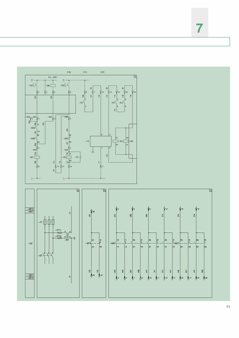
71
7

72
ELECTRIC CIRCUIT DIAGRAM
State of operation shownThe diagram is shown in the followingconditions:– contactor open– circuits de-energized– medium voltage fuses not blown.
Caption= Reference number of diagram figure
-TR = Feeder (see note B for contactor withelectrical latching; see note D for contac-tor with mechanical latching).
-BM = Device for checking continuity of theshunt opening release winding (seenote B for contactor with mechanicallatching)
-CC = Capacitor
-FF = Medium voltage fuses
-FF11, -FF12 = Fuses for voltage transformerprotection
-KA = Relay or auxiliary control contactor (useABB B16 or BC16 type contactor orequivalent apparatus)
-QC = Contactor
-MC = Closing electromagnet
-BB1, -BB2 = Contactor auxiliary contacts
-KC = Auxiliary closing relay (see note C)
-BF = Position contacts of the medium voltagefuses
-SC = Pushbutton or contact for closing contac-tor
-SO = Pushbutton or contact for openingcontactor
-BV = Voltage transformer
-RD = Diode
-XB11, -XB12 = Connectors for contactor circuits
-XB3 = Connectors of the accessories
-PC = Electric operation counter
-MO = Shunt opening release with possibility ofcontinuous control of the winding forcontactors with mechanical latching (seenote B).
Description of figuresFig. 1 = Contactor control circuits (see note B
for contactor with mechanical latching).
Fig. 2 = Control circuits of the contactor (24/60 V)(with mechanical latching).
Fig. 9 = Voltage transformer for contactorcontrol circuit power supply.
Fig. 11 = Electric operation counter circuit.
Fig. 12 = Medium voltage fuse auxiliary contactsfor contactor operating mechanism(cause contactor opening and preventclosure due to a fuse missing or blown)and for signalling.
Fig. 13 = Contactor auxiliary contacts.
NotesA) The contactor is only fitted with the accessories
listed in the order confirmation. To draw up theorder, consult this catalogue.
Only for contactor with electrical latchingB) In case of power supply voltage between 24
and 60 V DC, the feeder circuits (connectionsto sockets 10, 11, 14 and 19 of connector -XB11) must be made with 2.5 mm2 cross-sec-tion conductors.
Only for contactor with mechanical latchingB) The circuit for control of shunt opening re-
lease coil continuity must only be used for thisfunction (e.g.: to connect the “Control CoilContinuity” device or a relay or a signallinglamp absorbing a current no higher than20mA). Other uses jeopardise integrity of therelease.
C) To carry out the antipumping function, seediagram 1VCD400045.
D) In case of power supply voltage between 24and 60 V DC, the feeder circuits (connectionsto sockets 6 and 11 of connector -XB11) mustbe made with 2.5 mm2 cross-section conduc-tors.

73
7
Semiconductor diode (general symbol)
Make contact
Break contact
Closing position contact(limit switch)
Opening position contact(limit switch)
Contactor (make contact)
Control coil (general symbol)
Fuse (general symbol)
Electric impulse meter
Graphic symbols for electric diagrams (IEC 617 and CEI 3-14 ... 3-26 Standards)
Mechanical, pneumaticorhydraulic connection
Latching device, released
Pushbutton control
Electromagnetic control
Earth (general symbol)
Three conductors
Conductor connection or terminal
Capacitor (general symbol)
Socket and plug(female and male)

74


The data and illustrations are not binding. We reserve the right to make changes without notice in the course of technical development of the product.
Copyright 2009 ABB.All rights reserved.
Contact us
1VC
P00
0004
9 –
Rev
. I, e
n –
Tech
nica
l Cat
alog
ue -
200
9.02
(V-C
onta
ct)
ABB S.p.A. Power Products DivisionUnità Operativa Sace-MVVia Friuli, 4I-24044 DalmineTel.: +39 035 6952 111Fax: +39 035 6952 874e-mail: [email protected]
www.abb.com
ABB Calor Emag Mittelspannung GmbH Oberhausener Strasse 33 Petzower Strasse 8D-40472 Ratingen D-14542 Glindow Phone: +49(0)2102/12-1230, Fax: +49(0)2102/12-1916 E-mail: [email protected]
Internet:http://www.abb.de/calor