Embed Size (px)
Citation preview
IEC voltage detectors 118
Single phase comparators 120
Phase comparators 121
IEC equipment 122
Insulating sticks 123
Clamps 125
Overhead line systems 126
Cables 127
Underground systems 129
Sticks accessories 130
Medium voltage equipment
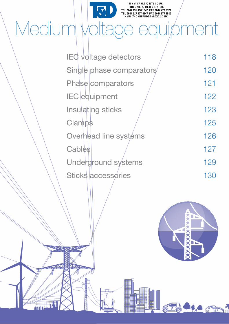
CC-875-C
CC-875-K
Robust housing.Weight of the detector: 450 gr.Size of the detector: Ø 59 x 270 mm.
CC-875-5,5/20-(*)
CC-875-10/30-(*)
CC-875-10/36-(*)
CC-875-11/33
50/60 Hz
50/60 Hz
50/60 Hz
50/60 Hz
118
IEC voltage detectors
IEC-61243-1IEC electronic Voltage Detectors, "Compactserie" for indoor and outdoor use
Ultimate technology of voltage detector “Head Capacitive Technology"Compact and light, it offers a wide band (10/36 kV).Operating check:By pressing the TEST button:- A red LED flashes on.- Powerful rated audible signal > 60 dB(A)/2 m.- When loosening the button. The timed green LED lights up. While remaining
on, it indicates the good working order of the detector.Characteristics:- Precise and stable operating threshold.- High environmental resistance (impacts, vibrations, moisture).- Temperature conditions: class N (IEC -61243-1 standard).- Use from 50 to 60 Hz.
ReferenceOperating voltage (KV)
5.5 - 20 kV
10 - 30 kV
10 - 36 kV
11 - 33 kV
(*) Specify type of mounting when ordering: C or K.Packaging: unit supplied complete in a case with batteries and contact electrodes (straight and V-shaped).
Total weight: 1100 g. Total size: 340 x 275 x 83 mm. For other voltages, please consult us.
Voltage presence is indicated by:- red flashing LED (very bright -visible at more than 20 m
in direct lighting),- powerful rated audible signal > 60 dB(A)/2 m.
Contact electrodes fitted to thehousing by screwing and are easily interchangeable.
9 V
9 V
9 V
9 V
450
450
450
450
gtype 6 LR 61
C K
End fittings:C: hexagonal 12 mm, for hexagonal end-fitting sticks, K: universal, for universal end-fitting sticks.Recommended stick: CE-4-21, CE-75. See page 123.
g Weight
Medium Voltage Equipment
Voltage detectors
119
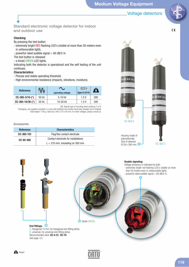
Standard electronic voltage detector for indoorand outdoor use
CheckingBy pressing the test button:- extremely bright RED flashing LED’s (visible at more than 50 meters even
in unfavourable light),- powerful rated audible signal > 60 dB/2 mThe test button is released:- a timed GREEN LED lights. Indicating both the detector is operational and the self testing of the unitcontinues.Characteristics:- Precise and stable operating threshold.- High environmental resistance (impacts, vibrations, moisture).
CC-363-K
CC-363-C
Double signaling:Voltage presence is indicated by both:- extremely bright red flashing LED’s (visible at more
than 50 meters even in unfavourable light),- powerful rated audible signal > 60 dB/2 m.
Housing made of polycarbonate.Size of detectorØ 59 x 390 mm.
CC-365-101
CC-92-492
Reference Characteristics
Flag/Vee contact electrode
Contact electrode for installations
L = 310 mm, insulating on 300 mm
Diode GREEN.
CC-365-3/10-(*)
CC-365-10/30-(*)
50 Hz
50 Hz
Reference
3-10 kV
10-30 kV
(*) Specify type of mounting when ordering: C or K.Packaging: unit supplied complete in a case with batteries and contact electrodes (straight and V-shaped).
Total weight: 1100 g. Total size: 340 x 275 x 83 mm. For other voltages, please consult us.
1.5 V
1.5 V
500
500
Accessories
C K
End fittings:C: hexagonal 12 mm, for hexagonal end-fitting sticks, K: universal, for universal end-fitting sticks.Recommended stick: CE-4-21, CE-75. See page 123.
g Weight
(operating voltage)g
type 6 LR 61
Single phase comparators
IEC-61481
120
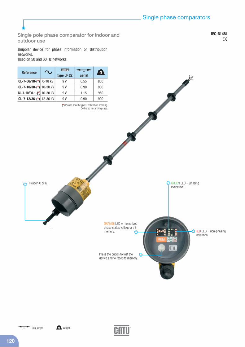
Unipolar device for phase information on distribution networks.Used on 50 and 60 Hz networks.
Single pole phase comparator for indoor andoutdoor use
Press the button to test the device and to reset its memory.
CL-7-06/18-(*)
CL-7-10/30-(*)
CL-7-10/30-1-(*)
CL-7-12/36-(*)
6-18 kV
10-30 kV
10-30 kV
12-36 kV
0.55
0.90
1.15
0.90
9 V
9 V
9 V
9 V
(*) Please specify type C or K when ordering.Delivered in carrying case.
Reference m
aerialtype LF 22
GREEN LED = phasingindication.
Fixation C or K.
RED LED = non-phasingindication.
ORANGE LED = memorizedphase status voltage are inmemory.
850
900
950
900
g
g Weightmm Total length
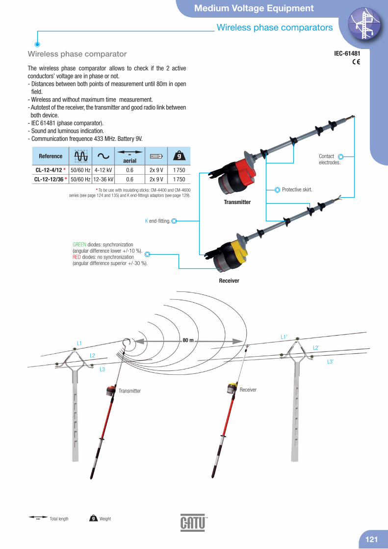
GREEN diodes: synchronization (angular difference lower +/-10 %). RED diodes: no synchronization(angular difference superior +/-30 %).
Medium Voltage Equipment
121
Wireless phase comparators
IEC-61481
Receiver
Transmitter
Wireless phase comparator
The wireless phase comparator allows to check if the 2 activeconductors’ voltage are in phase or not.- Distances between both points of measurement until 80m in open
field.- Wireless and without maximum time measurement.- Autotest of the receiver, the transmitter and good radio link between both device.
- IEC 61481 (phase comparator).- Sound and luminous indication.- Communication frequence 433 MHz. Battery 9V.
ReceiverTransmitter
L1
L2
L3
L1’
L2’
L3’
80 m
Contact electrodes.
K end-fitting.
CL-12-4/12 *
CL-12-12/36 *
4-12 kV
12-36 kV
0.6
0.6
2x 9 V
2x 9 V
* To be use with insulating sticks: CM-4400 and CM-4600 series (see page 124 and 135) and K end-fittings adaptors (see page 129).
Reference
1 750
1 750
g
50/60 Hz
50/60 Hz
aerial
Protective skirt.
g Weightmm Total length
m
122
IEC equipment
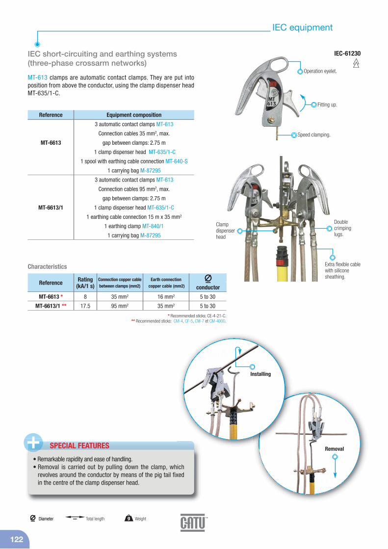
IEC short-circuiting and earthing systems(three-phase crossarm networks)
MT-613 clamps are automatic contact clamps. They are put into position from above the conductor, using the clamp dispenser head MT-635/1-C.
IEC-61230
SPECIAL FEATURES+• Remarkable rapidity and ease of handling.• Removal is carried out by pulling down the clamp, which
revolves around the conductor by means of the pig tail fixedin the centre of the clamp dispenser head.
MT-6613
MT-6613/1
Reference Equipment composition
3 automatic contact clamps MT-613
Connection cables 35 mm2, max.
gap between clamps: 2.75 m
1 clamp dispenser head MT-635/1-C
1 spool with earthing cable connection MT-640-S
1 carrying bag M-87295
3 automatic contact clamps MT-613
Connection cables 95 mm2, max.
gap between clamps: 2.75 m
1 clamp dispenser head MT-635/1-C
1 earthing cable connection 15 m x 35 mm2
1 earthing clamp MT-840/1
1 carrying bag M-87295
Operation eyelet.
Removal
Fitting up.
Speed clamping.
C lamp dispenser head
Extra flexible cablewith siliconesheathing.
Double crimpinglugs.
Installing
g Weightmm
Diametermm
Diameter mm Total length
* Recommended sticks: CE-4-21-C.** Recommended sticks: CM-4, CF-5, CM-7 et CM-4000.
MT-6613 *
MT-6613/1 **
Reference Rating(kA/1 s)
8
17.5
Connection copper cablebetween clamps (mm2)
35 mm2
95 mm2
16 mm2
35 mm2
5 to 30
5 to 30
Earth connectioncopper cable (mm2)
mm
conductor
Characteristics

IEC-61235
Medium Voltage Equipment
123
Insulating sticks
Telescopic sticks for voltage detector
Use in wet conditions.
CE-4-21-C
CE-75-C
CF-5
CM-7-10-A
Yellow lower element madeof resin polyester/glass fiber41 mm diameter base tube.
For sticks and voltage detectors. Plastic.
Wall mounted supports
CE-4-21-(*)
CM-7-10-A
CE-75-(*)
90 kV
Extension*
75 kV
41/32
36
41/32
1.15
–
1.5
2
1
2
1 500
1 000
1 200
(*) Please specify type C or K when ordering.Delivered with wall mounted supports CI-10-D.
* For CE-4-21.
Telescopic stickcontains 2 elements made ofresin polyester/glass fiber foamfilled tube.
Lockable button.
Element madeof resin polyes-ter/glass fiber.
Referencemm
m gFolded up m Isolated skirts
polycarbonate Ø 100 mm,height 90 mm ,resistant shocks.
Fixed length sticks
Use in wet conditions.
CF-5-40-(*)
CF-5-90-(*)
CF-5-110-(*)
CF-5-170-(*)
40 kV
90 kV
110 kV
170 kV
1.50
2.00
2.50
3.00
1 150
1 550
2 000
2 400
1
1
2
3
(*) Please specify type C or K when ordering.
Reference gm
Skirtnbr
CI-06-D
CI-10-D
CI-12-D
CI-08
28-30
32-36
28-30
16-20
Reference mm
Top
36 max
58 max
56 max
36 max
mm
Bottom
Delivered with wood screws.
Element made ofglass fiber/resinepoxy foam filled of 36 mmdiameter (**).
An upper orange element made ofglass fiber/resin epoxy foam filledof 32 mm diameter (**).
Top Bottom
IEC-61235
124
CM-4400-J
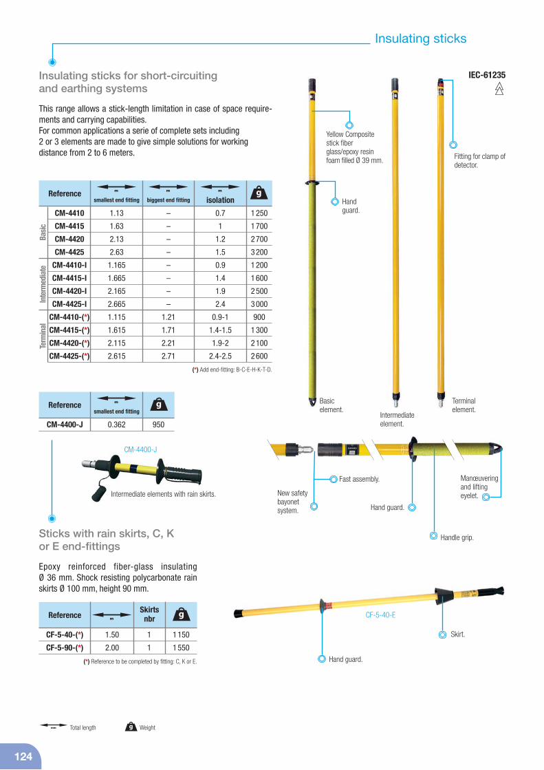
Insulating sticks for short-circuiting and earthing systems
This range allows a stick-length limitation in case of space require-ments and carrying capabilities.For common applications a serie of complete sets including2 or 3 elements are made to give simple solutions for workingdistance from 2 to 6 meters.
Sticks with rain skirts, C, K or E end-fittings
Epoxy reinforced fiber-glass insulating Ø 36 mm. Shock resisting polycarbonate rainskirts Ø 100 mm, height 90 mm.
CF-5-40-E
New safetybayonetsystem. Hand guard.
Manœuveringand lifting eyelet.
Fitting for clamp ofdetector.
Fast assembly.
Intermediate elements with rain skirts.
Intermediateelement.
Basic element.
Terminalelement.
Hand guard.
Skirt.CF-5-40-(*)
CF-5-90-(*)
1.50
2.00
1 150
1 550
1
1
(*) Reference to be completed by fitting: C, K or E.
gm
Skirtsnbr
1 250
1 700
2 700
3 200
1 200
1 600
2 500
3 000
900
1 300
2 100
2 600
g
CM-4410
CM-4415
CM-4420
CM-4425
CM-4410-I
CM-4415-I
CM-4420-I
CM-4425-I
CM-4410-(*)
CM-4415-(*)
CM-4420-(*)
CM-4425-(*)
1.13
1.63
2.13
2.63
1.165
1.665
2.165
2.665
1.115
1.615
2.115
2.615
m
smallest end fitting
–
–
–
–
–
–
–
–
1.21
1.71
2.21
2.71
m
biggest end fitting
0.7
1
1.2
1.5
0.9
1.4
1.9
2.4
0.9-1
1.4-1.5
1.9-2
2.4-2.5
m
isolation
Basi
cIn
term
edia
teTe
rmin
al
(*) Add end-fitting: B-C-E-H-K-T-D.
950
Reference g
CM-4400-J 0.362
m
smallest end fitting
Insulating sticks
Handguard.
Handle grip.
Reference
Reference
g Weightmm Total length
Yellow Compositestick fiberglass/epoxy resinfoam filled Ø 39 mm.
Medium Voltage Equipment
Clamp dispenser heads and accessories
125
Reference Headfor 3 clamps
Headfor 4 clamps
Withpigtail hook
MT-633-C ■ ■
MT-633-K ■ ■
MT-633-S ■ ■
MT-634/1-C/K ■ ■
Reference Silicone cable (mm2)
Length (m)
MT-640-S 16 16
MT-641-S 16 25
Reference Weight (kg) Conductors (mm)
MT-840/1 0.48 Ø 6-25 0-25
MT-843 0.95 Ø 6-35 0-35MT-840/1 MT-843
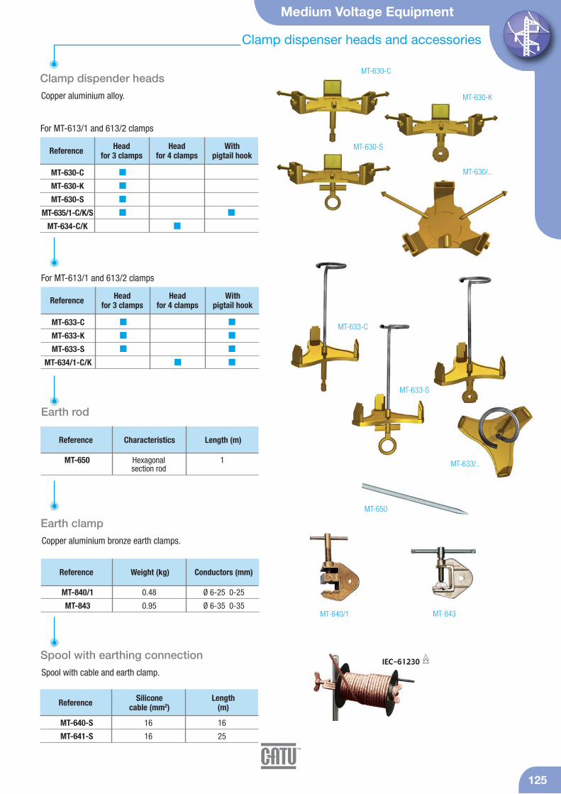
MT-630-C
MT-633-C
MT-633/..
MT-633-S
MT-630-S
Clamp dispender heads
Copper aluminium alloy.
Earth clamp
Copper aluminium bronze earth clamps.
Reference Characteristics Length (m)
MT-650 Hexagonal 1section rod
Earth rod
For MT-613/1 and 613/2 clamps
MT-650
Spool with earthing connection
Spool with cable and earth clamp.IEC-61230
Reference Headfor 3 clamps
Headfor 4 clamps
Withpigtail hook
MT-630-C ■
MT-630-K ■
MT-630-S ■
MT-635/1-C/K/S ■ ■
MT-634-C/K ■
For MT-613/1 and 613/2 clamps
MT-630-K
MT-630/..

126
Overhead line systems
Short-circuiting and earthing systems
Installed from the ground on conductors up to10.50 m.
MT-546
MT-650
On-the-spot voltage testingwith a CC-875 detector attached to a metal polewith a combination Ve/flagantenna.
MT-508/36
MT-508/46
Reference Rating(kA/1 s)
8
8
3-22
3-22
mm
conductor
Composition
3 telescopic metallic sticks 3 elementsL = 6.00/2.37 m - 2.4 kg - MT-512/36
1 insulating stick 2 elements 1.65 m - MT-531
Reel for 3 cables 10 m x 35 mm2 withearth connect. for attachment to stick - MT-543/35
1 earth rod 1 m - MT-650
1 bag. 2.50 x 0.30 x 0.15 - 10.5 kg - M-87-127
3 telescopic metallic sticks 4 elementsL = 5.10/1.62 m - 2.1 kg - MT-512/46
1 insulating stick2 elements 1.65 m - MT-531
1 insulating intermediatestick element 1.65 m - CM-4-165-B
1 stick lifter - MT-546
Reel for 3 cables 10 m x 35 mm2 withearth connect. for attachment to stick - MT-543/35
1 earth rod 1 m - MT-650
1 bag M-87-208
Reference
MT-508/36
MT-508/46
MT-512/36
MT-531
CM-4-165-B
MT-543/35
MT-650
Easier installation features.Self locking contact clamp: powerful conductor clampingand very good performance atshort-circuiting, does not slide.
Re-inforced insulatingstick (36 mm dia.).
More rigid metallic stick.Lower tube 30.6 mm dia.Upper tube 16 mm dia.
On all models: Reinforced insulating pole: Epoxy/fibre-glass resin over Ø 36 mmPV foam with a non-skidarea. This equipment can beused for rigid deployed polesfor easy installation.
Self-locking clampNo spring for easier mainte-nance, removal, and greaterreliability.
mmDiameter

Medium Voltage Equipment
127
Cables
* IEC-61230Copper cables
Extra flexible braided multi-strand cables. Transparent PVC sheath, withcable section identification. Transparent silicon sheath according toIEC-61230. Resistant to temperature variations (-40 °C to +70 °C) withdouble IEC triangle marked on cable section.
Copper cables only: Heating curves (Gut & Grundberg method).
Copper cables only: Heating curves - 300 °C.
FUSI ÓN
500100015002000
10
16
25
30
35
40
50
70
95
3000
4000
5000
6000
7000
8000
9000
10. 000
15. 000
20. 000
25. 000
30. 000
35. 000
40. 000
0 0, 5 1 2 3 4 5sA
120 mm2
300°C
500100015002000 10
16
2530
40
50
70
95
3000
4000
5000
6000
7000
8000
9000
10. 000
15. 000
20. 000
25. 000
30. 000
35. 000
40. 000
0 0, 5 1 2 3 4 5s
0 0, 5 1 2 3 4 5s
A
120 mm2
35
Fusion 300 °C
M-24-10
M-24-16
M-24-25
M-24-30
M-24-35
M-24-40
M-24-50
M-24-70
M-24-75
M-24-95
M-24-120
M-24-150
–
M-24-16-S
M-24-25-S
–
M-24-35-S
M-24-40-S
M-24-50-S
M-24-70-S
–
M-24-95-S
M-24-120-S
M-24-150-S
Reference
A B*Rating
(kA/1 s)Cable
Weight (kg/m) Ø (mm)
2
3.5
6
7
8
10
12
16
20
20
30
40
0.105
0.156
0.5
0.330
0.86
0.440
0.545
0.768
0.800
1.000
1.280
1.630
4.5
5.6
7.5
8
9
9.5
10
12
12
14
17
19
Section(mm2)
10
16
25
30
35
40
50
70
75
95
120
150
Copper cables.
A: Transparent PVC sheath, with cable section identification.B: Transparent silicon sheath according to IEC-61230. Resistant to temperature variations
(-40 °C to +70 °C) with double IEC triangle marked on cable section.
128
Cables
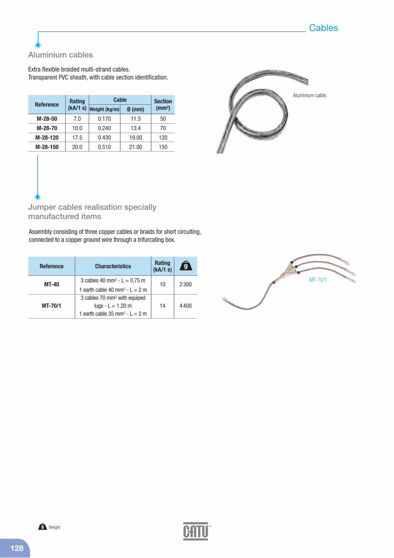
Aluminium cables
Extra flexible braided multi-strand cables.Transparent PVC sheath, with cable section identification.
MT-70/1
Jumper cables realisation specially manufactured items
Assembly consisting of three copper cables or braids for short circuiting,connected to a copper ground wire through a trifurcating box.
M-28-50
M-28-70
M-28-120
M-28-150
Reference Rating(kA/1 s)
Cable
Weight (kg/m) Ø (mm)
7.0
10.0
17.5
20.0
0.170
0.240
0.430
0.510
11.5
13.4
19.00
21.00
Section(mm2)
50
70
120
150
MT-40
MT-70/1
Reference Characteristics
3 cables 40 mm2 - L = 0.75 m
1 earth cable 40 mm2 - L = 2 m3 cables 70 mm2 with equiped
lugs - L = 1.20 m1 earth cable 35 mm2 - L = 2 m
Rating(kA/1 s)
10
14
2 300
4 400
g
Aluminium cable.
g Weight
Medium Voltage Equipment
129
Underground systems
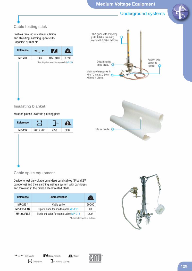
Cable testing stick
Enables piercing of cable insulation and shielding, earthing up to 50 kV.Capacity: 70 mm dia.
Carrying Case available separately (MP-02).Ratchet typeoperatinghandle.
MP-211 1.60 8 750Ø 60 maxi
Reference gm mm
Double cuttingangle blade.
Cable-guide with protectingguide. 0.60 m insulatingsleeve with 0.80 m extender.
Must be placed over the piercing point
Insulating blanket
960
Reference g
MP-212 Hole for handle.
mm
900 X 900 Ø 50
mm
Cable spike equipment
Device to test the voltage on underground cables (1st and 2nd
categories) and their earthing, using a system with cartridges and throwing in the cable a steel treated blade.
Cable spike
Spare blade for spade-cable MP-213
Blade extractor for spade-cable MP-213
Reference Characteristics
20 000
20
200
g
MP-213 *
MP-213/LAM
MP-213/EXT* Delivered complete in suitcase.
Multistrand copper earth wire 70 mm2 x 2.50 m with earth clamp.
g Weightmm Total length mm Clamp capacity.
mm Dimensions mm Maximal opening.
130
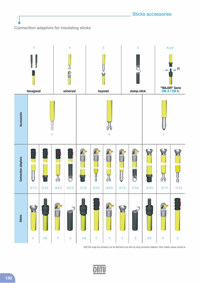
Sticks accessories
E
Connection adaptors for insulating sticks
Acce
ssor
ies
Conn
ectio
n ad
apto
rsSt
icks
C K S A ou B
C EK
CI-7-C CI-3-C CI-6-C CI-5-C CI-3-K CI-4-K CI-6-K CI-7-K CI-5-K CI-3-E CI-7-E CI-4-E
E A B K S A B C K E S A B K C
21
With this range any accessory can be attached to any stick by using connection adaptors. Other models, please consult us.
hexagonal universal bayonet clamp-stick"MAJOR" Serie CM-4 / CM-6.
Medium Voltage Equipment
131
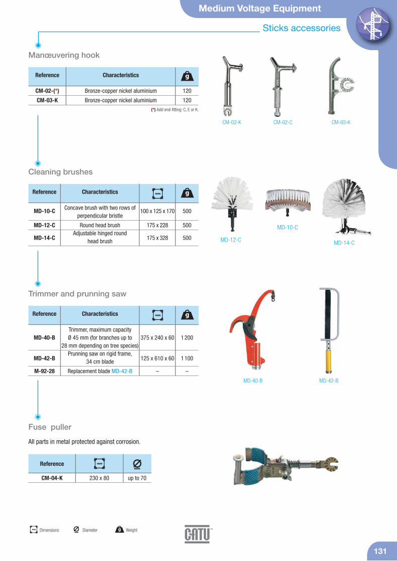
Sticks accessories
Manœuvering hook
Bronze-copper nickel aluminium
Bronze-copper nickel aluminium
Reference Characteristics
120
120
g
CM-02-(*)
CM-03-K(*) Add end-fitting: C, E or K.
CM-02-C CM-03-KCM-02-K
Cleaning brushes
Trimmer and prunning saw
Fuse puller
All parts in metal protected against corrosion.
MD-12-C MD-14-C
MD-10-C
500
500
500
Reference g
MD-10-C
MD-12-C
MD-14-C
mm
100 x 125 x 170
175 x 228
175 x 328
Concave brush with two rows of perpendicular bristle
Round head brushAdjustable hinged round
head brush
Characteristics
1 200
1 100
–
Reference g
MD-40-B
MD-42-B
M-92-28
mm
375 x 240 x 60
125 x 610 x 60
–
Trimmer, maximum capacityØ 45 mm (for branches up to
28 mm depending on tree species)Prunning saw on rigid frame,
34 cm blade
Replacement blade MD-42-B
Characteristics
MD-40-B MD-42-B
CM-04-K
Reference
up to 70
mm
mm
230 x 80
g Weightmm
Diametermm Dimensions
132
Sticks accessories
mm Dimensions
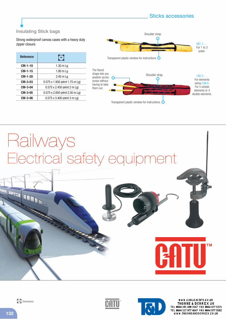
Insulating Stick bags
Strong waterproof canvas cases with a heavy dutyzipper closure.
Reference
CM-1-10
CM-1-15
CM-1-20
CM-3-03
CM-3-04
CM-3-05
CM-3-06
mm
1.30 m Lg
1.80 m Lg
2.40 m Lg
0.575 x 1.950 (elmt 1.75 m Lg)
0.575 x 2.450 (elmt 2 m Lg)
0.575 x 2.850 (elmt 2.50 m Lg)
0.575 x 3.400 (elmt 3 m Lg)
Shoulder strap.
The flaredshape lets youposition acces-sories withouthaving to takethem out.
Transparent plastic window for instructions.
Transparent plastic window for instructions.
Shoulder strap.
MC-1-…For 1 to 3
poles.
CM-3-…For elements series CM-6. For 5 simple
elements or 4double elements.
m