Embed Size (px)
Citation preview
Mediatrix 4102 Hardware Installation Guide
Mediatrix 4102
Revision 1
2016-02-24
Table of Contents
media5corp.com
Table of Contents
Mediatrix 4102 Series Gateways 4
Safety Recommendations and Information 5
Danger, Warning, Caution, and Note Definitions 5Electrical Safety Guidelines 5General Safety Practices 6Electrostatic Discharge Prevention 7Translated Warning Definition 7
Requirements 9
Location Requirements 9Wiring Guidelines 9Mediatrix 4102 Characteristics 10
Getting Started 11
Installation Check List 11Package Check List 12Cleaning Instructions 12Mounting Tools and Equipment 12Connectors and Indicators 13
Installing the Mediatrix Unit 15
Installing the Unit on a Flat Surface 15Installing the Unit on the Wall 16
Table of Contents
media5corp.com
Connecting the Telephony Cables 17Using IPv4 to Connect the Mediatrix unit to a Network with a DHCP 17Using IPv4 to Connect the Mediatrix Unit to a Network without a DHCP 18Verifying the Installation 19
Cables 20
FXS Connections (RJ-11) 2010/100 Ethernet Connection (RJ-45) 20
Troubleshooting 22
Locating the Product Serial Number 22Troubleshooting 23LED Patterns 23RESET/DEFAULT Button 24Partial Reset 25Performing a Partial Reset 26
Factory Reset 27Performing a Factory Reset 27
Disabling the Rescue Interface 28
Standards Compliance and Disclaimers 29
Supported Standards 29Disclaimers 30
Copyright Notice 33
Mediatrix 4102 Hardware Installation Guide 4
media5corp.com
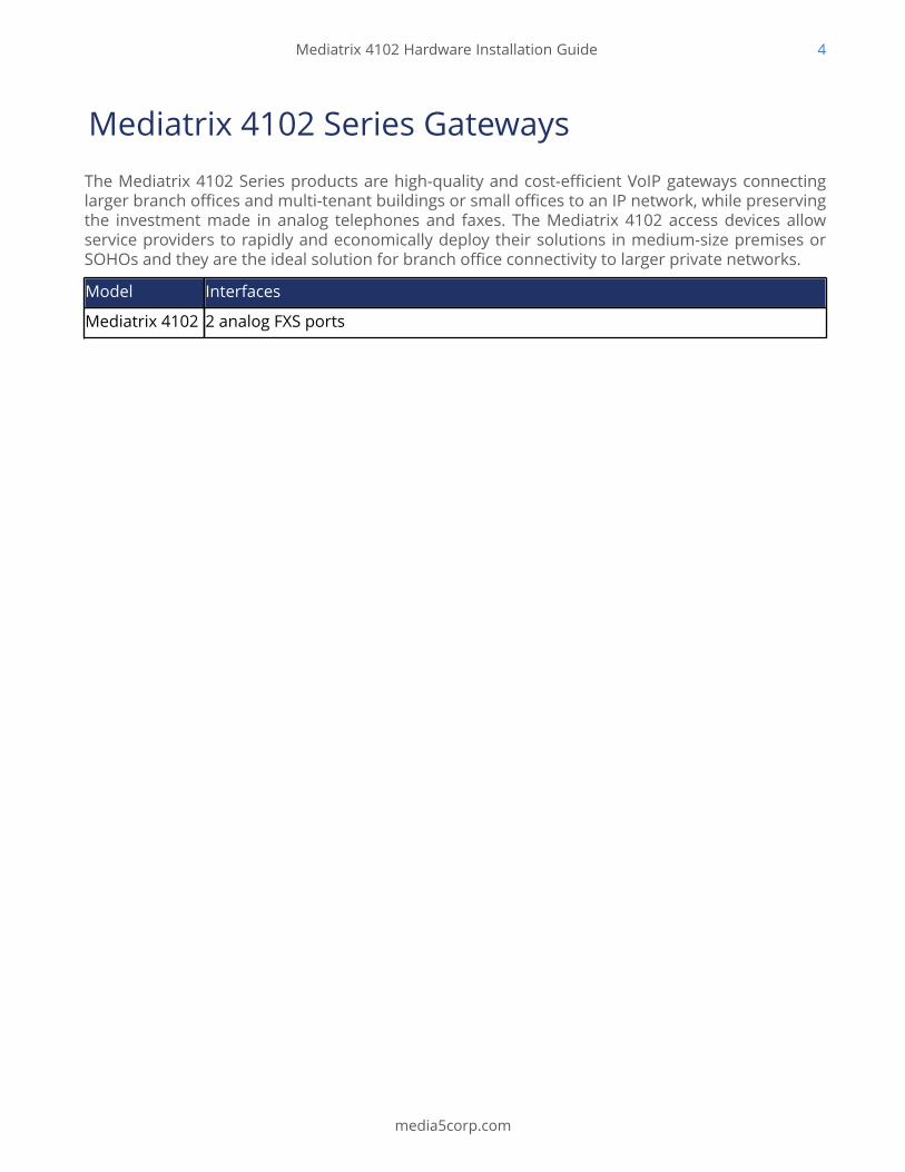
Mediatrix 4102 Series GatewaysThe Mediatrix 4102 Series products are high-quality and cost-efficient VoIP gateways connectinglarger branch offices and multi-tenant buildings or small offices to an IP network, while preservingthe investment made in analog telephones and faxes. The Mediatrix 4102 access devices allowservice providers to rapidly and economically deploy their solutions in medium-size premises orSOHOs and they are the ideal solution for branch office connectivity to larger private networks.
Model Interfaces
Mediatrix 4102 2 analog FXS ports
Mediatrix 4102 Hardware Installation Guide 5
media5corp.com
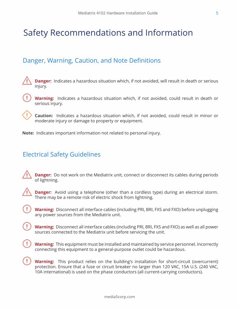
Safety Recommendations and Information
Danger, Warning, Caution, and Note Definitions
Danger: Indicates a hazardous situation which, if not avoided, will result in death or seriousinjury.
Warning: Indicates a hazardous situation which, if not avoided, could result in death orserious injury.
Caution: Indicates a hazardous situation which, if not avoided, could result in minor ormoderate injury or damage to property or equipment.
Note: Indicates important information not related to personal injury.
Electrical Safety Guidelines
Danger: Do not work on the Mediatrix unit, connect or disconnect its cables during periodsof lightning.
Danger: Avoid using a telephone (other than a cordless type) during an electrical storm.There may be a remote risk of electric shock from lightning.
Warning: Disconnect all interface cables (including PRI, BRI, FXS and FXO) before unpluggingany power sources from the Mediatrix unit.
Warning: Disconnect all interface cables (including PRI, BRI, FXS and FXO) as well as all powersources connected to the Mediatrix unit before servicing the unit.
Warning: This equipment must be installed and maintained by service personnel. Incorrectlyconnecting this equipment to a general-purpose outlet could be hazardous.
Warning: This product relies on the building's installation for short-circuit (overcurrent)protection. Ensure that a fuse or circuit breaker no larger than 120 VAC, 15A U.S. (240 VAC,10A international) is used on the phase conductors (all current-carrying conductors).
Mediatrix 4102 Hardware Installation Guide 6
media5corp.com
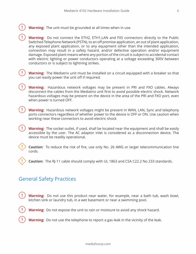
Warning: The unit must be grounded at all times when in use.
Warning: Do not connect the ETH2, ETH1,LAN and FXS connectors directly to the PublicSwitched Telephone Network (PSTN), to an off premise application, an out of plant application,any exposed plant application, or to any equipment other than the intended application,connection may result in a safety hazard, and/or defective operation and/or equipmentdamage. Exposed plant means where any portion of the circuit is subject to accidental contactwith electric lighting or power conductors operating at a voltage exceeding 300V betweenconductors or is subject to lightning strikes.
Warning: The Mediatrix unit must be installed on a circuit equipped with a breaker so thatyou can easily power the unit off if required.
Warning: Hazardous network voltages may be present in PRI and FXO cables. Alwaysdisconnect the cables from the Mediatrix unit first to avoid possible electric shock. Networkhazardous voltages may be present on the device in the area of the PRI and FXO port, evenwhen power is turned OFF.
Warning: Hazardous network voltages might be present in WAN, LAN, Sync and telephonyports connectors regardless of whether power to the device is OFF or ON. Use caution whenworking near these connectors to avoid electric shock
Warning: The socket outlet, if used, shall be located near the equipment and shall be easilyaccessible by the user. The AC adaptor inlet is considered as a disconnection device. Thedevice must be readily operational.
Caution: To reduce the risk of fire, use only No. 26 AWG or larger telecommunication linecords.
Caution: The RJ-11 cable should comply with UL 1863 and CSA C22.2 No 233 standards.
General Safety Practices
Warning: Do not use this product near water, for example, near a bath tub, wash bowl,kitchen sink or laundry tub, in a wet basement or near a swimming pool.
Warning: Do not expose the unit to rain or moisture to avoid any shock hazard.
Warning: Do not use the telephone to report a gas leak in the vicinity of the leak.
Mediatrix 4102 Hardware Installation Guide 7
media5corp.com
Warning: Do not get this product wet or pour liquids into it.
Warning: Ultimate disposal of this product should be handled according to all national lawsand regulations.
• Keep your Mediatrix unit clear and dust-free during and after installation.
• Locate the emergency power-off switch for the room in which you are working. Then, if anelectrical accident occurs, you can act quickly to turn off the power.
• Do not work alone if potentially hazardous conditions exist.
• Never assume that power is disconnected from a circuit. Always check.
• Do not perform any action that creates a potential hazard to people or makes the equipmentunsafe.
• Do not open or disassemble this product.
• Do not perform any action that creates a potential hazard to people or makes the equipmentunsafe.
• The unit should be located at 20 cm from your monitor, computer casing or other peripheralincluding speakers.
• When the unit is brought from a cold to a warm environment, condensation, that might beharmful to the unit, may occur. If this is the case, wait one hour before powering the unit.
Electrostatic Discharge Prevention
• When working on a Mediatrix unit, always wear an ESD wrist strap, ensuring that it makes agood contact with your bare skin.
• Attach the ESD wrist strap end to an earth ground i.e. the grounding screw on the back of theMediatrix unit or on an unpainted bare metal spot of a grounded equipment rack.
Translated Warning Definition
Warning: Means danger. You are in a situation that could cause bodily injury. Before youwork on any equipment, you must be aware of the hazards involved with electrical circuitryand familiar with standard practices for preventing accidents.
Waarschuwing: (Waarschuwing) Dit waarschuwingssymbool betekent gevaar. U overtreatin een situatie die lichamelijk letsel kan veroorzaken. Voordat u aan enige apparatuur gaat
Mediatrix 4102 Hardware Installation Guide 8
media5corp.com
werken, dient u zich bewust te zijn van de bij elektrische schakelingen betrokken risico's endient u op de hoogte te zijn van standaard maatregelen om ongelukken te voorkomen.
Varoitus: (Varoitus) Tämä varoitusmerkki merkitsee vaaraa. Olet tilanteessa, joka voijohtaa ruumiinvammaan. Ennen kuin työskentelet minkään laitteiston parissa, ota selvääsähkökytkentöihin liittyvistä vaaroista ja tavanomaisista onnettomuuksien ehkäisykeinoista.
Attention : (Avertissement)Ce symbole d'avertissement indique un danger. Vous voustrouvez dans une situation pouvant causer des blessures ou des dommages corporels. Avantde travailler sur un équipement, soyez conscient des dangers posés par les circuits électriqueset familiarisez-vous avec les procédures couramment utilisées pour éviter les accidents.
Warnung: (Warnung) Dieses Warnsymbol bedeutet Gefahr. Sie befinden sich in einerSituation, die zu einer Körperverletzung führen könnte. Bevor Sie mit der Arbeit anirgendeinem Gerät beginnen, seien Sie sich der mit elektrischen Stromkreisen verbundenenGefahren und der Standardpraktiken zur Vermeidung von Unfällen bewußt
Avvertenza: (Avvertenza) Questo simbolo di avvertenza indica un pericolo. La situazionepotrebbe causare infortuni alle persone. Prima di lavorare su qualsiasi apparecchiatura,occorre conoscere i pericoli relativi ai circuiti elettrici ed essere al corrente delle pratichestandard per la prevenzione di incidenti.
Advarsel: (Advarsel) Dette varselsymbolet betyr fare. Du befinner deg i en situasjon somkan føre til personskade. Før du utfører arbeid på utstyr, må du vare oppmerksom på defaremomentene som elektriske kretser innebærer, samt gjøre deg kjent med vanlig praksisnår det gjelder å unngå ulykker.
Aviso: (Aviso) Este símbolo de aviso indica perigo. Encontra-se numa situação que lhe poderácausar danos físicos. Antes de começar a trabalhar com qualquer equipamento, familiarize-se com os perigos relacionados com circuitos eléctricos, e com quaisquer práticas comunsque possam prevenir possíveis acidentes..
¡Advertencia!: (¡Advertencia!) Este símbolo de aviso significa peligro. Existe riesgo para suintegridad física. Antes de manipular cualquier equipo, considerar los riesgos que entrañala corriente eléctrica y familiarizarse con los procedimientos estándar de prevención deaccidentes.
Varning: (Varning) Denna varningssymbol signalerar fara. Du befinner dig i en situation somkan leda till personskada. Innan du utför arbete på någon utrustning måste du vara medvetenom farorna med elkretsar och känna till vanligt förfarande för att förebygga skador.
Mediatrix 4102 Hardware Installation Guide 9
media5corp.com
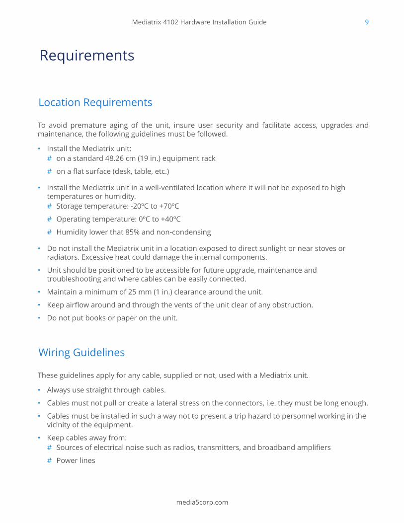
Requirements
Location Requirements
To avoid premature aging of the unit, insure user security and facilitate access, upgrades andmaintenance, the following guidelines must be followed.
• Install the Mediatrix unit:# on a standard 48.26 cm (19 in.) equipment rack
# on a flat surface (desk, table, etc.)
• Install the Mediatrix unit in a well-ventilated location where it will not be exposed to hightemperatures or humidity.# Storage temperature: -20ºC to +70ºC
# Operating temperature: 0ºC to +40ºC
# Humidity lower that 85% and non-condensing
• Do not install the Mediatrix unit in a location exposed to direct sunlight or near stoves orradiators. Excessive heat could damage the internal components.
• Unit should be positioned to be accessible for future upgrade, maintenance andtroubleshooting and where cables can be easily connected.
• Maintain a minimum of 25 mm (1 in.) clearance around the unit.
• Keep airflow around and through the vents of the unit clear of any obstruction.
• Do not put books or paper on the unit.
Wiring Guidelines
These guidelines apply for any cable, supplied or not, used with a Mediatrix unit.
• Always use straight through cables.
• Cables must not pull or create a lateral stress on the connectors, i.e. they must be long enough.
• Cables must be installed in such a way not to present a trip hazard to personnel working in thevicinity of the equipment.
• Keep cables away from:# Sources of electrical noise such as radios, transmitters, and broadband amplifiers
# Power lines
Mediatrix 4102 Hardware Installation Guide 10
media5corp.com
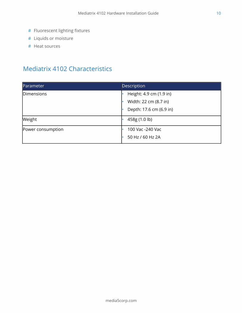
# Fluorescent lighting fixtures
# Liquids or moisture
# Heat sources
Mediatrix 4102 Characteristics
Parameter Description
Dimensions • Height: 4.9 cm (1.9 in)
• Width: 22 cm (8.7 in)
• Depth: 17.6 cm (6.9 in)
Weight • 458g (1.0 lb)
Power consumption • 100 Vac -240 Vac
• 50 Hz / 60 Hz 2A
Mediatrix 4102 Hardware Installation Guide 11
media5corp.com
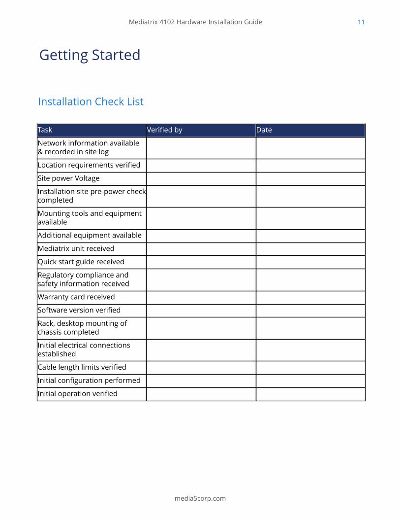
Getting Started
Installation Check List
Task Verified by Date
Network information available& recorded in site log
Location requirements verified
Site power Voltage
Installation site pre-power checkcompleted
Mounting tools and equipmentavailable
Additional equipment available
Mediatrix unit received
Quick start guide received
Regulatory compliance andsafety information received
Warranty card received
Software version verified
Rack, desktop mounting ofchassis completed
Initial electrical connectionsestablished
Cable length limits verified
Initial configuration performed
Initial operation verified
Mediatrix 4102 Hardware Installation Guide 12
media5corp.com
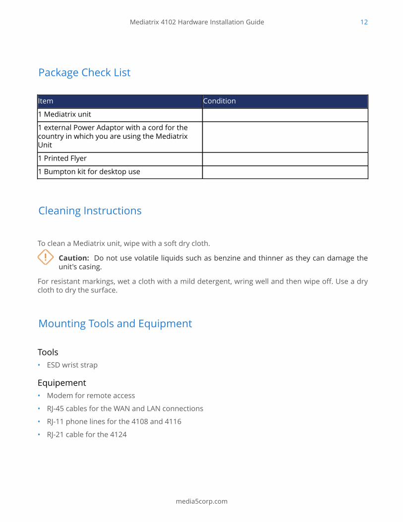
Package Check List
Item Condition
1 Mediatrix unit
1 external Power Adaptor with a cord for thecountry in which you are using the MediatrixUnit
1 Printed Flyer
1 Bumpton kit for desktop use
Cleaning Instructions
To clean a Mediatrix unit, wipe with a soft dry cloth.
Caution: Do not use volatile liquids such as benzine and thinner as they can damage theunit's casing.
For resistant markings, wet a cloth with a mild detergent, wring well and then wipe off. Use a drycloth to dry the surface.
Mounting Tools and Equipment
Tools• ESD wrist strap
Equipement• Modem for remote access
• RJ-45 cables for the WAN and LAN connections
• RJ-11 phone lines for the 4108 and 4116
• RJ-21 cable for the 4124
Mediatrix 4102 Hardware Installation Guide 13
media5corp.com
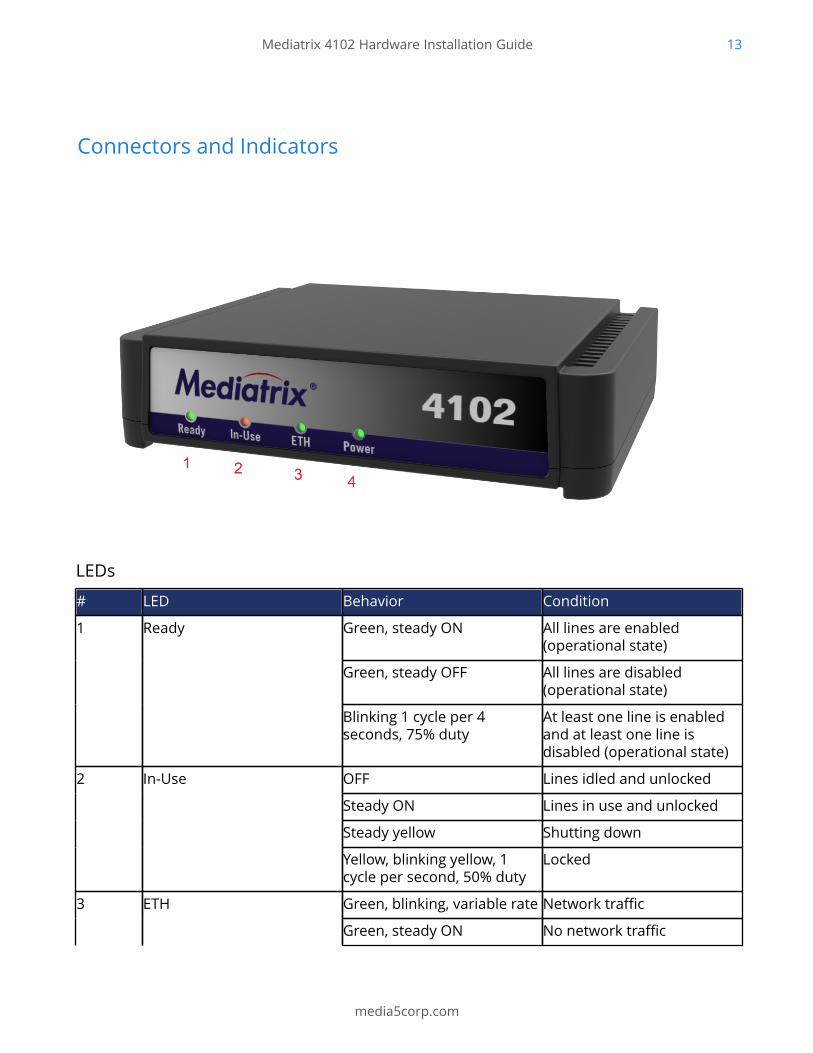
Connectors and Indicators
LEDs
# LED Behavior Condition
Green, steady ON All lines are enabled(operational state)
Green, steady OFF All lines are disabled(operational state)
1 Ready
Blinking 1 cycle per 4seconds, 75% duty
At least one line is enabledand at least one line isdisabled (operational state)
OFF Lines idled and unlocked
Steady ON Lines in use and unlocked
Steady yellow Shutting down
2 In-Use
Yellow, blinking yellow, 1cycle per second, 50% duty
Locked
Green, blinking, variable rate Network traffic3 ETH
Green, steady ON No network traffic
Mediatrix 4102 Hardware Installation Guide 14
media5corp.com
# LED Behavior Condition
OFF Not connected
Amber, steady ON Restart completed
OFF Indicates that the unit is notconnected
5 Power
Blinking, 1 Hz, 50% duty Restart in progress
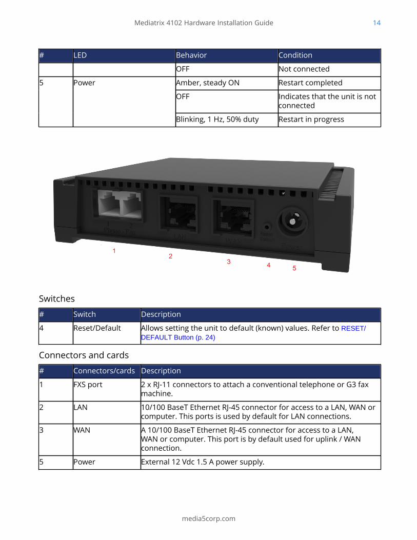
Switches
# Switch Description
4 Reset/Default Allows setting the unit to default (known) values. Refer to RESET/DEFAULT Button (p. 24)
Connectors and cards
# Connectors/cards Description
1 FXS port 2 x RJ-11 connectors to attach a conventional telephone or G3 faxmachine.
2 LAN 10/100 BaseT Ethernet RJ-45 connector for access to a LAN, WAN orcomputer. This ports is used by default for LAN connections.
3 WAN A 10/100 BaseT Ethernet RJ-45 connector for access to a LAN,WAN or computer. This port is by default used for uplink / WANconnection.
5 Power External 12 Vdc 1.5 A power supply.
Mediatrix 4102 Hardware Installation Guide 15
media5corp.com
Installing the Mediatrix Unit
Before you start
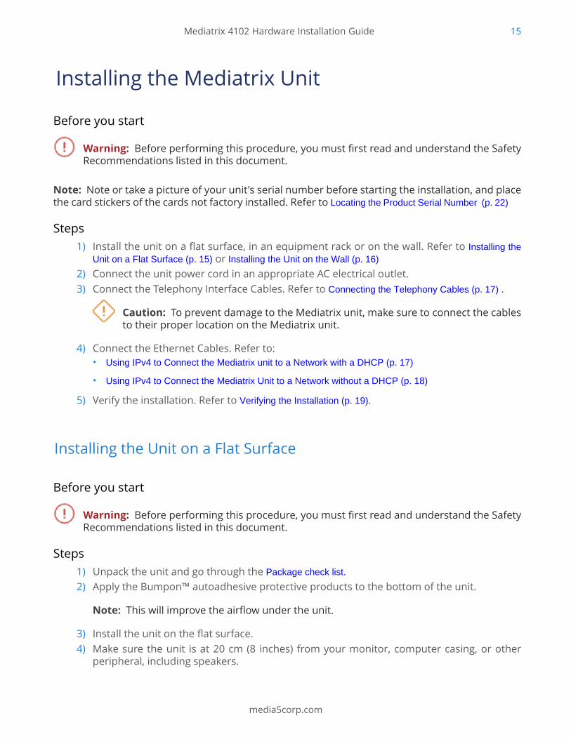
Warning: Before performing this procedure, you must first read and understand the SafetyRecommendations listed in this document.
Note: Note or take a picture of your unit's serial number before starting the installation, and placethe card stickers of the cards not factory installed. Refer to Locating the Product Serial Number (p. 22)
Steps1) Install the unit on a flat surface, in an equipment rack or on the wall. Refer to Installing the
Unit on a Flat Surface (p. 15) or Installing the Unit on the Wall (p. 16)
2) Connect the unit power cord in an appropriate AC electrical outlet.3) Connect the Telephony Interface Cables. Refer to Connecting the Telephony Cables (p. 17) .
Caution: To prevent damage to the Mediatrix unit, make sure to connect the cablesto their proper location on the Mediatrix unit.
4) Connect the Ethernet Cables. Refer to:• Using IPv4 to Connect the Mediatrix unit to a Network with a DHCP (p. 17)
• Using IPv4 to Connect the Mediatrix Unit to a Network without a DHCP (p. 18)
5) Verify the installation. Refer to Verifying the Installation (p. 19).
Installing the Unit on a Flat Surface
Before you start
Warning: Before performing this procedure, you must first read and understand the SafetyRecommendations listed in this document.
Steps1) Unpack the unit and go through the Package check list.
2) Apply the Bumpon™ autoadhesive protective products to the bottom of the unit.
Note: This will improve the airflow under the unit.
3) Install the unit on the flat surface.4) Make sure the unit is at 20 cm (8 inches) from your monitor, computer casing, or other
peripheral, including speakers.

Mediatrix 4102 Hardware Installation Guide 16
media5corp.com
Next StepConnecting the Telephony Cables (p. 17)
Installing the Unit on the Wall
Before you start
IMPORTANT: Before performing this procedure, you must first read and understand theSafety Recommendations listed in this document.
InformationConsider writing down the Product Serial Number on a document easy to access before performingthe installation of the unit. Refer to Locating the Product Serial Number (p. 22)
Steps1) Unpack the unit and go through the Package check list.
2) Do not connect any cables to the unit.3) Make sure the wall is smooth, flat, dry and sturdy.
Note: If necessary, install a 250 mm x 200 mm x 12 mm (10 inches x 8 inches x 0,5 inches)plywood on the wall.
4) Apply the Bumpon™ autoadhesive protection to the bottom of the unit.
Note: This will improve the airflow under the unit.
5) Position the unit against the wall (plywood).6) Mark the position of the screw holes on the wall.7) Drill two holes on the markings.8) Install a screw in each hole.9) Align the screw holes of the unit over the screws installed on the wall, and hang the unit.

Mediatrix 4102 Hardware Installation Guide 17
media5corp.com
Next StepConnecting the Telephony Cables (p. 17)
Connecting the Telephony Cables
Information
Note: To prevent damage to the Mediatrix unit, make sure to connect the cables to their properlocation on the Mediatrix unit.
Steps1) Wear an ESD wrist strap, ensuring it makes good contact with your bare skin.2) Attach the ESD wrist strap end to an earth ground (unpainted bare metal spot of a grounded
equipment rack).3) Make sure the circuit breakers of AC power sources used to power the Mediatrix unit are
OFF.4) Make sure the provided power cable is connected to the Mediatrix unit and in an
appropriate AC electrical outlet.5) Connect faxes, phones or a PBX to the FXS card.
Next StepUsing IPv4 to Connect the Mediatrix unit to a Network with a DHCP (p. 17)
Using IPv4 to Connect the Mediatrix Unit to a Network without a DHCP (p. 18)
Using IPv4 to Connect the Mediatrix unit to a Network with a DHCP
Before you start• Make sure that your network connection is working.
• If your unit does not have an FXS port, or if you do not have access to the DHCP server's logs,then use the Using IPv4 to Connect the Mediatrix Unit to a Network without a DHCP (p. 18) procedure.
Steps1) Wear an ESD wrist strap, ensuring it makes good contact with your bare skin.2) Attach the ESD wrist strap end to an earth ground (unpainted bare metal spot of a grounded
equipment rack).

Mediatrix 4102 Hardware Installation Guide 18
media5corp.com
3) Make sure the circuit breakers of AC power sources used to power the Mediatrix unit areOFF.
4) Make sure the provided external Power Adaptor is connected to the DC connector of theMediatrix unit and in an appropriate AC electrical outlet.
5) Connect a 10/100 BaseT Ethernet RJ-45 cable into the connector of the Mediatrix unit.6) Connect the other end of the cable to a router/switch connected to your Network.7) Validate the installation.8) Turn ON the AC power sources that are used to power the Mediatrix unit at the circuit
breaker
Note: When the unit is brought from a cold to a warm environment, condensation, thatmight be harmful to the unit, may occur. If this is the case, wait one hour before connectingthe power cord.
9) If you have an FXS port, dial *#*0 to get the IP address or consult the DHCP server's logsto find out your IP address.
ResultThe Power LED on the unit will be flashing when the unit performs a DHCP query. It will becomesolid once it successfully gets an IP address from the DHCP server. At this point, you can now usethe DHCP IP address to access your unit's management interface.
Next StepVerifying the Installation (p. 19)
Using IPv4 to Connect the Mediatrix Unit to a Network without aDHCP
Before you start• Your computer must be set to use the 192.168.0.11 private IP address.
• Make sure that your network connection is working.
Steps1) Wear an ESD wrist strap, ensuring it makes good contact with your bare skin.2) Attach the ESD wrist strap end to an earth ground (unpainted bare metal spot of a grounded
equipment rack).3) Make sure the circuit breakers of AC power sources used to power the Mediatrix unit are
OFF.4) Make sure the provided external Power Adaptor is connected to the DC connector of the
Mediatrix unit and in an appropriate AC electrical outlet.

Mediatrix 4102 Hardware Installation Guide 19
media5corp.com
5) Connect a 10/100 BaseT Ethernet RJ-45 cable into the Ethernet connector of the Mediatrixunit.
6) Connect the other end of the cable into your PC.7) Validate the installation.8) Turn ON the AC power sources that are used to power the Mediatrix unit at the circuit
breaker.
Note: When the unit is brought from a cold to a warm environment, condensation, thatmight be harmful to the unit, may occur. If this is the case, wait one hour before connectingthe power cord.
ResultYou can now use the 192.168.0.10 IP address to access your unit's management interface.
Next StepVerifying the Installation (p. 19)
Verifying the Installation
Steps1) Contact the Mediatrix unit with an SNMP browser.2) Contact the Mediatrix unit via the CLI.3) Contact the Mediatrix unit via the Web Browser.4) Ping the Mediatrix unit.
Mediatrix 4102 Hardware Installation Guide 20
media5corp.com
Cables
FXS Connections (RJ-11)
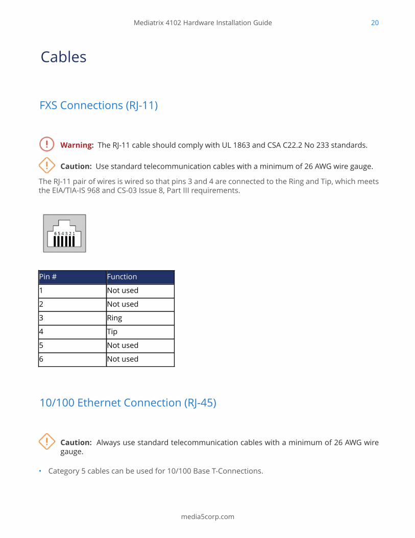
Warning: The RJ-11 cable should comply with UL 1863 and CSA C22.2 No 233 standards.
Caution: Use standard telecommunication cables with a minimum of 26 AWG wire gauge.
The RJ-11 pair of wires is wired so that pins 3 and 4 are connected to the Ring and Tip, which meetsthe EIA/TIA-IS 968 and CS-03 Issue 8, Part III requirements.
Pin # Function
1 Not used
2 Not used
3 Ring
4 Tip
5 Not used
6 Not used
10/100 Ethernet Connection (RJ-45)
Caution: Always use standard telecommunication cables with a minimum of 26 AWG wiregauge.
• Category 5 cables can be used for 10/100 Base T-Connections.

Mediatrix 4102 Hardware Installation Guide 21
media5corp.com
• It is possible to use either a crossover or a straight Ethernet cable as the Mediatrix unitsperform automatic MDI/ MDIX detection, meaning that they adapt to the type of cablesconnected to them. The Auto MDI/ MDIX feature only works when the unit are configured inauto detect mode, which is the default mode.
Pin Name Description TIA/EIA 568A TIA/EIA 568B
1 Bl_DA+/Tx+ Bi-directional pair A+(Transmit+)
white/green white/orange
2 Bl_DA-/Tx- Bi-directional pair A-(Transmit-)
green orange
3 Bl_DB+/Rx+ Bi-directional pair B+(Received+)
white/orange white/green
4 not used
5 not used
6 Bl_DB-/Rx- Bi-directional pair B-(Receive -)
orange green
7 not used
8 not used
Mediatrix 4102 Hardware Installation Guide 22
media5corp.com
Troubleshooting
Locating the Product Serial Number
Before you start
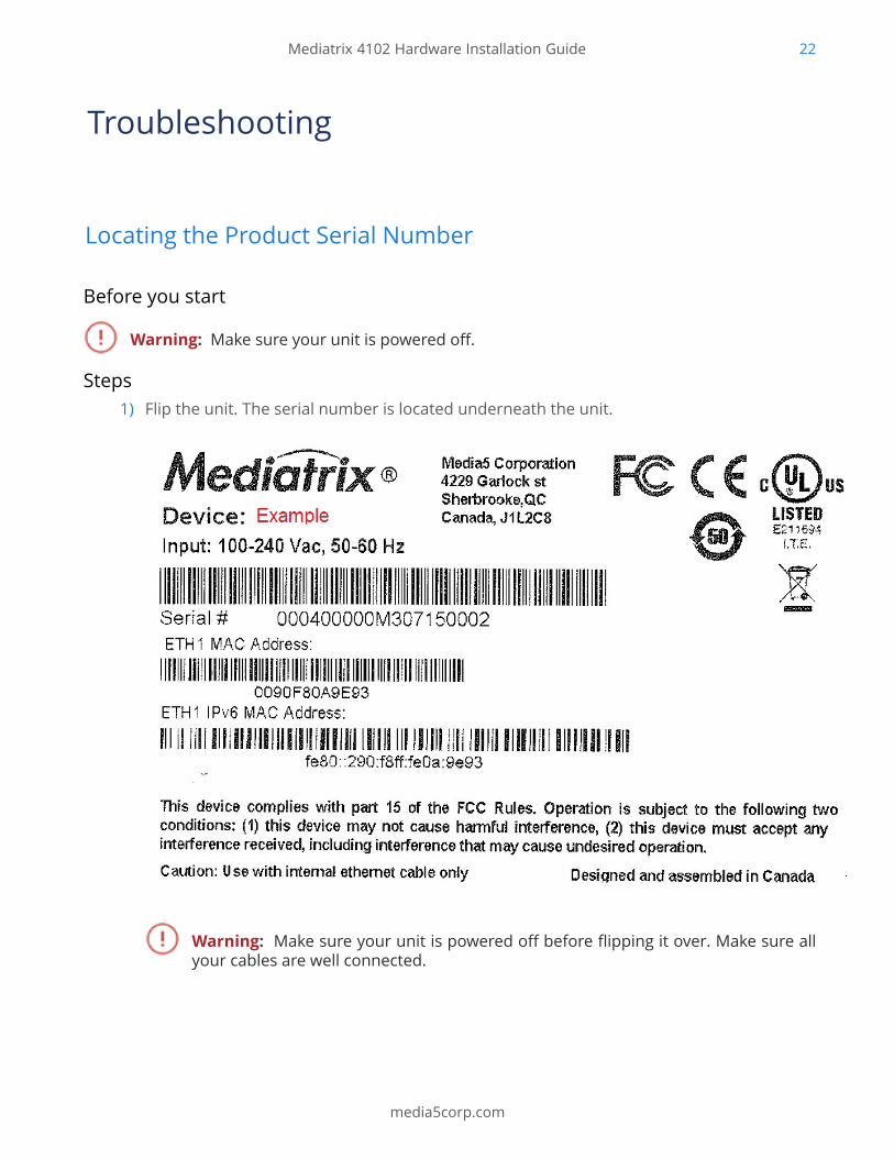
Warning: Make sure your unit is powered off.
Steps1) Flip the unit. The serial number is located underneath the unit.
Warning: Make sure your unit is powered off before flipping it over. Make sure allyour cables are well connected.
Mediatrix 4102 Hardware Installation Guide 23
media5corp.com
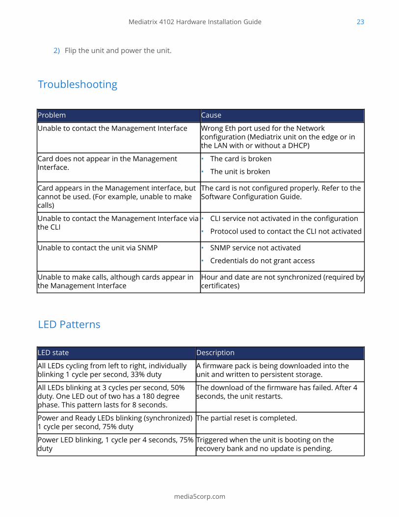
2) Flip the unit and power the unit.
Troubleshooting
Problem Cause
Unable to contact the Management Interface Wrong Eth port used for the Networkconfiguration (Mediatrix unit on the edge or inthe LAN with or without a DHCP)
Card does not appear in the ManagementInterface.
• The card is broken
• The unit is broken
Card appears in the Management interface, butcannot be used. (For example, unable to makecalls)
The card is not configured properly. Refer to theSoftware Configuration Guide.
Unable to contact the Management Interface viathe CLI
• CLI service not activated in the configuration
• Protocol used to contact the CLI not activated
Unable to contact the unit via SNMP • SNMP service not activated
• Credentials do not grant access
Unable to make calls, although cards appear inthe Management Interface
Hour and date are not synchronized (required bycertificates)
LED Patterns
LED state Description
All LEDs cycling from left to right, individuallyblinking 1 cycle per second, 33% duty
A firmware pack is being downloaded into theunit and written to persistent storage.
All LEDs blinking at 3 cycles per second, 50%duty. One LED out of two has a 180 degreephase. This pattern lasts for 8 seconds.
The download of the firmware has failed. After 4seconds, the unit restarts.
Power and Ready LEDs blinking (synchronized)1 cycle per second, 75% duty
The partial reset is completed.
Power LED blinking, 1 cycle per 4 seconds, 75%duty
Triggered when the unit is booting on therecovery bank and no update is pending.

Mediatrix 4102 Hardware Installation Guide 24
media5corp.com
LED state Description
Power LED blinking green 3 cycles per second,50% duty
Waiting for DHCP (IPv4 or IPv6) answer or IPv6router advertisement or PPPoE connection. No IpAddress configured.
All LEDs blinking green, 3Hz, 50% duty Waiting for DHCP (IPv4 or IPv6) answer or IPv6router advertisement or PPPoE connection.
Ready LED OFF, all other LEDs cycling fromright to left, left to right.
The unit tries to download and install a firmwaregiven by the Network Rescue server.
RESET/DEFAULT Button
The Reset/Default switch can be used to perform a partial or factory reset while the unit is running.
In other words, the Reset/Default switch can be used to:• Cancel an action that was started.
• Revert to known factory settings if the Mediatrix unit refuses to work properly for any reasonor the connection to the network is lost.
• Reconfigure a unit.
The Reset/Default switch will generate different actions depending on the amount of time thebutton is held.
Pressing Time Action Comment LED Pattern
2 to 6 seconds Restarts the Mediatrixunit.
No changes are madeto the Mediatrix unitsettings.
Power1 blinking, allother LEDs OFF
7 to 11 seconds Initiates a Partial Resetof the Mediatrix unit.
Restarts the unit in aknown and static statewhile keeping mostof the configurationunchanged.
All LEDs blinking, 1cycleper second, 50% duty
12 to 16 seconds Initiates a Factory Resetof the Mediatrix unit
Reverts the unit backto its default factorysettings.
All LEDs steady ON
17 seconds and more No action is taken.This is useful if youaccidentally pushedthe button and do notneed and action to beapplied.
The action is ignored. N/A
Mediatrix 4102 Hardware Installation Guide 25
media5corp.com
Partial Reset
The partial reset provides a way to contact the Mediatrix unit in a known and static state whilekeeping most of the configuration unchanged.
A partial reset can be performed at the initial start-up of the Mediatrix unit or on a unit alreadyin use where the configuration was modified in such a way that the user can longer access thesystem by the web page or otherwise. In both cases, the user will access the Rescue Interface withthe Rescue Network Interface using either a static IPv4 address (192.168.0.1 ) or an IPv6 Link Localaddress connection. These connections give access to the Rescue Management Interface where theconfiguration of a new unit can be completed and where an existing configuration can be modified.
By default the Rescue Network Interface is disabled. When a partial reset is performed, theRescue network Interface becomes enabled. Once the configuration has been modified to solve theproblem that required the partial reset, it is important to access the Management interface usingthe Network Interface Configuration defined for your set-up, and to disable the Rescue NetworkInterface to make sure that you are no longer working in the Rescue Network Interface.
Performing a partial reset on a new unit will not modify the configuration, as it has not yet beenmodified to your needs. However, a partial reset performed on a unit already in use will :• Cancel the changes that were being modified but not yet applied to the configuration
• Remove all Network and Local Firewall rules.
• Remove all Nat rules.
• Disable any Network Interface in conflict with the Network Rescue Interface.
• Configure and enable the Rescue Network Interface to:# use the Eth1 link, or the same link as the one used by the Uplink Network Interface.
# set the IP address to 192.168.0.1 and the Network Mask to 255.255.255.0.
# set the IPv6 link-local address on all network links. The IPv6 link-local address can be foundunderneath the unit.
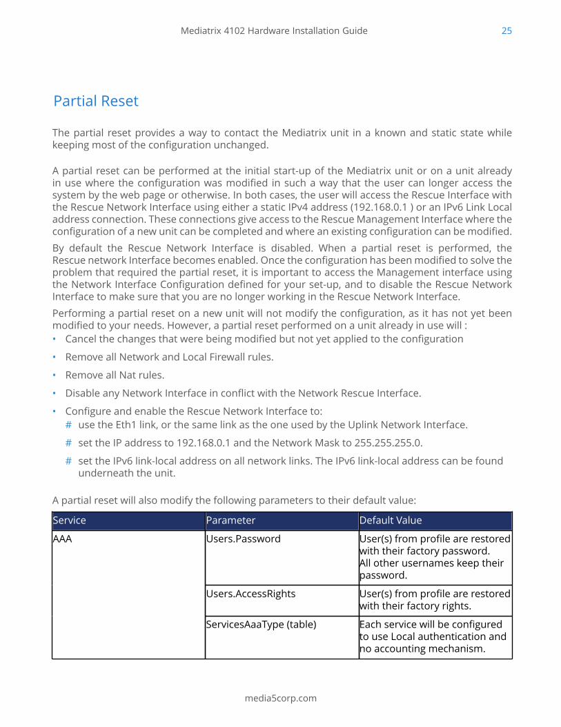
A partial reset will also modify the following parameters to their default value:
Service Parameter Default Value
Users.Password User(s) from profile are restoredwith their factory password.All other usernames keep theirpassword.
Users.AccessRights User(s) from profile are restoredwith their factory rights.
AAA
ServicesAaaType (table) Each service will be configuredto use Local authentication andno accounting mechanism.
Mediatrix 4102 Hardware Installation Guide 26
media5corp.com
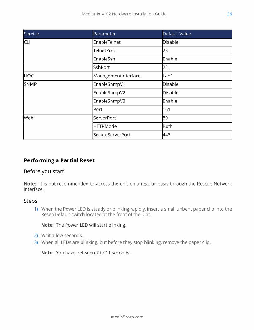
Service Parameter Default Value
EnableTelnet Disable
TelnetPort 23
EnableSsh Enable
CLI
SshPort 22
HOC ManagementInterface Lan1
EnableSnmpV1 Disable
EnableSnmpV2 Disable
EnableSnmpV3 Enable
SNMP
Port 161
ServerPort 80
HTTPMode Both
Web
SecureServerPort 443
Performing a Partial Reset
Before you start
Note: It is not recommended to access the unit on a regular basis through the Rescue NetworkInterface.
Steps1) When the Power LED is steady or blinking rapidly, insert a small unbent paper clip into the
Reset/Default switch located at the front of the unit.
Note: The Power LED will start blinking.
2) Wait a few seconds.3) When all LEDs are blinking, but before they stop blinking, remove the paper clip.
Note: You have between 7 to 11 seconds.
Mediatrix 4102 Hardware Installation Guide 27
media5corp.com
ResultThe Rescue Network Interface is displayed when accessing the Management Interface. Severalparameters and services are modified.
What to do nextRemove the changes in your configuration that caused the system to no longer respond, and donot forget to disable the Rescue Network interface.
Factory Reset
The Factory reset reverts the Mediatrix unit back to its default factory settings.
It deletes the persistent configuration parameters of the unit, including:• User files stored in the File service
• Certificates except the ones factory installed
• Log files of the File service
The Factory reset should be performed with the Mediatrix unit connected to a network with accessto a DHCP server. If the unit cannot find a DHCP server, it will sent requests indefinitely. A FactoryReset can be triggered either:• directly on the unit. Refer to Performing a Factory Reset (p. 27).
• via the web interface of the Mediatrix unit. (Management/Firmware Upgrade).
• via the Command Line Interface of the Mediatrix unit by using the fpu.defaultsettingparameter.
Performing a Factory Reset
InformationThe Factory reset alters any persistent configuration data of the Mediatrix unit.
Note: The Mediatrix unit must be connected to a network with access to a DHCP server. If the unitcannot find a DHCP server, it will send requests indefinitely.
Steps1) Power the Mediatrix unit Off.2) Insert a small, unbent paper clip into the Reset/Default hole located at the rear of the
Mediatrix unit.3) While pressing the Reset/Default button, restart the unit.
Do not depress before the LEDs stop blinking and are steadily ON. This can take up to 30 seconds.
Mediatrix 4102 Hardware Installation Guide 28
media5corp.com
4) Release the paper clip.
ResultAll configuration parameters are reset to their default value. When the Mediatrix unit has finished itsprovisioning sequence, it is ready to be used with a DHCP provided IP address and MIB parameters.This procedure can also be performed at run time.
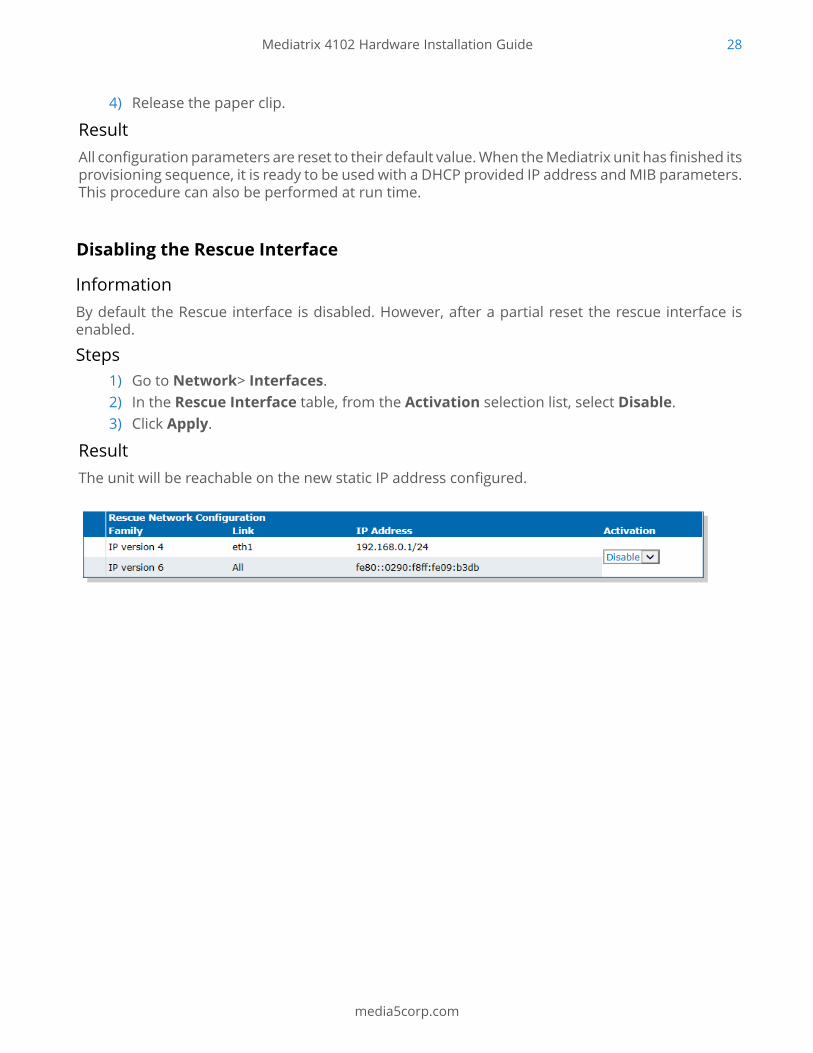
Disabling the Rescue Interface
InformationBy default the Rescue interface is disabled. However, after a partial reset the rescue interface isenabled.
Steps1) Go to Network> Interfaces.2) In the Rescue Interface table, from the Activation selection list, select Disable.3) Click Apply.
ResultThe unit will be reachable on the new static IP address configured.
Mediatrix 4102 Hardware Installation Guide 29
media5corp.com
Standards Compliance and Disclaimers
Supported Standards
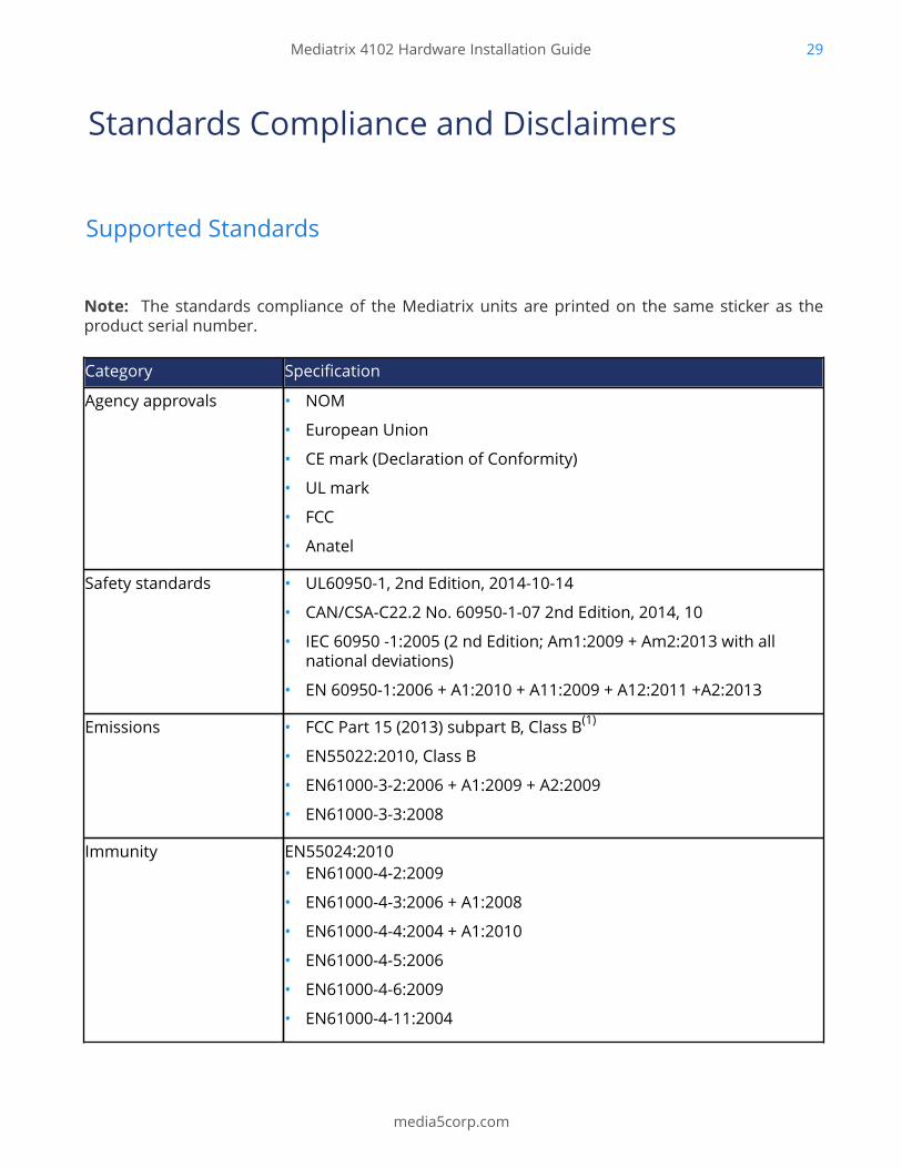
Note: The standards compliance of the Mediatrix units are printed on the same sticker as theproduct serial number.
Category Specification
Agency approvals • NOM
• European Union
• CE mark (Declaration of Conformity)
• UL mark
• FCC
• Anatel
Safety standards • UL60950-1, 2nd Edition, 2014-10-14
• CAN/CSA-C22.2 No. 60950-1-07 2nd Edition, 2014, 10
• IEC 60950 -1:2005 (2 nd Edition; Am1:2009 + Am2:2013 with allnational deviations)
• EN 60950-1:2006 + A1:2010 + A11:2009 + A12:2011 +A2:2013
Emissions • FCC Part 15 (2013) subpart B, Class B(1)
• EN55022:2010, Class B
• EN61000-3-2:2006 + A1:2009 + A2:2009
• EN61000-3-3:2008
Immunity EN55024:2010• EN61000-4-2:2009
• EN61000-4-3:2006 + A1:2008
• EN61000-4-4:2004 + A1:2010
• EN61000-4-5:2006
• EN61000-4-6:2009
• EN61000-4-11:2004
Mediatrix 4102 Hardware Installation Guide 30
media5corp.com
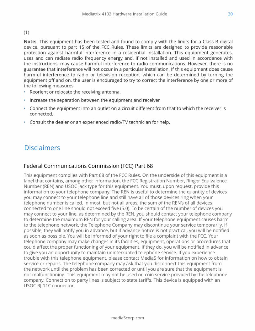
(1)
Note: This equipment has been tested and found to comply with the limits for a Class B digitaldevice, pursuant to part 15 of the FCC Rules. These limits are designed to provide reasonableprotection against harmful interference in a residential installation. This equipment generates,uses and can radiate radio frequency energy and, if not installed and used in accordance withthe instructions, may cause harmful interference to radio communications. However, there is noguarantee that interference will not occur in a particular installation. If this equipment does causeharmful interference to radio or television reception, which can be determined by turning theequipment off and on, the user is encouraged to try to correct the interference by one or more ofthe following measures:• Reorient or relocate the receiving antenna.
• Increase the separation between the equipment and receiver
• Connect the equipment into an outlet on a circuit different from that to which the receiver isconnected.
• Consult the dealer or an experienced radio/TV technician for help.
Disclaimers
Federal Communications Commission (FCC) Part 68
This equipment complies with Part 68 of the FCC Rules. On the underside of this equipment is alabel that contains, among other information, the FCC Registration Number, Ringer EquivalenceNumber (REN) and USOC jack type for this equipment. You must, upon request, provide thisinformation to your telephone company. The REN is useful to determine the quantity of devicesyou may connect to your telephone line and still have all of those devices ring when yourtelephone number is called. In most, but not all areas, the sum of the REN’s of all devicesconnected to one line should not exceed five (5.0). To be certain of the number of devices youmay connect to your line, as determined by the REN, you should contact your telephone companyto determine the maximum REN for your calling area. If your telephone equipment causes harmto the telephone network, the Telephone Company may discontinue your service temporarily. Ifpossible, they will notify you in advance, but if advance notice is not practical, you will be notifiedas soon as possible. You will be informed of your right to file a complaint with the FCC. Yourtelephone company may make changes in its facilities, equipment, operations or procedures thatcould affect the proper functioning of your equipment. If they do, you will be notified in advanceto give you an opportunity to maintain uninterrupted telephone service. If you experiencetrouble with this telephone equipment, please contact Media5 for information on how to obtainservice or repairs. The telephone company may ask that you disconnect this equipment fromthe network until the problem has been corrected or until you are sure that the equipment isnot malfunctioning. This equipment may not be used on coin service provided by the telephonecompany. Connection to party lines is subject to state tariffs. This device is equipped with anUSOC RJ-11C connector.

Mediatrix 4102 Hardware Installation Guide 31
media5corp.com
Industry Canada
This Class B digital apparatus complies with Canadian ICES-003. Cet appareil numérique de laclasse B est conforme à la norme NMB-003 du Canada. The Industry Canada Label identifiescertified equipment. This certification means that the equipment meets telecommunicationsnetwork protective, operational and safety requirements as prescribed in the appropriateTerminal Equipment Technical Requirements document(s). The Department does not guaranteethe equipment will operate to the user's satisfaction. Before installing this equipment,users should ensure that it is permissible to be connected to the facilities of the localtelecommunications company. The equipment must also be installed using an acceptable methodof connection. The customer should be aware that compliance with the above conditions maynot prevent degradation of service in some situations. Repairs to certified equipment shouldbe coordinated by a representative designated by the supplier. Any repairs or alterations madeby the user to this equipment, or equipment malfunctions, may give the telecommunicationscompany cause to request the user to disconnect the equipment. Users should ensure for theirown protection that the electrical ground connections of the power utility, telephone lines andinternal metallic water pipe system, if present, are connected together. This precaution may beparticularly important in rural areas.
Note: Users should not attempt to make such connections themselves, but should contact theappropriate electric inspection authority, or electrician, as appropriate.
Note: The Ringer Equivalence Number (REN) for this terminal equipment is 0.0. The RingerEquivalence Number (REN) assigned to each terminal device provides an indication of the maximumnumber of terminals allowed to be connected to a telephone interface. The termination on aninterface may consist of any combination of devices subject only to the requirement that the sumof the Ringer Equivalence Number of all the devices does not exceed 5.
Note: This equipment meets the applicable Industry Canada Terminal Equipment TechnicalSpecifications. This is confirmed by the registration number. The abbreviation, IC, before theregistration number signifies that registration was performed based on a Declaration of Conformityindicating that Industry Canada technical specifications were met. It does not imply that IndustryCanada approved the equipment.
CE Marking
DECLARATION OF CONFORMITY
We, Media5 Corporation, located at 4229 Garlock st. Sherbrooke, Québec, Canada J1L 2C8, declarethat for the hereinafter mentioned product the presumption of conformity with the applicableessential requirements of Directives 2014/30/EC and 2014/35/EC European parliament (EMCand LVD directives)is given. Any unauthorized modification of the product voids this declaration.For a copy of the original signed Declaration Of Conformity please contact Media5 at the aboveaddress.

Mediatrix 4102 Hardware Installation Guide 32
media5corp.com
RoHS Declaration Of Compliance
This Mediatrix unit is in compliance with the Council Directives 2002/95/EC and2011/65/EC on the restriction of the use of certain hazardous substances in electrical andelectronic equipment
RoHS China
Altitude of Operation
Translated from Chinese as "Used onlyat altitudes not more than 2000 m above sea level" or similar.
"Only used in not-tropical climate regions."

Mediatrix 4102 Hardware Installation Guide 33
media5corp.com
Copyright NoticeCopyright ™ © 2016 Media5 Corporation.
This document contains information proprietary to Media5 Corporation.
Media5 Corporation reserves all rights to this document as well as to the Intellectual Property ofthe document and the technology and know-how that it includes and represents.
This publication cannot be reproduced, neither in whole nor in part, in any form whatsoever, withoutwritten prior approval by Media5 Corporation.
Media5 Corporation reserves the right to revise this publication and make changes at any time andwithout the obligation to notify any person and/or entity of such revisions and/or changes.