Embed Size (px)
Citation preview
Media Workflow Platform Architecture for Avid ISIS® This document provides recommendations from Avid and Cisco Systems to enable Broadcasters to deploy Enterprise Network Architectures supporting the Media Workflow Platform (MWP) This document addresses the deployment for ISIS® 1.x up to 2.1
Updates to this document will be required to support future versions of this product Version 1.0
© 2010 Cisco | Avid. All rights reserved. 2
Table of Contents
1 Purpose of this Document ...................................................................................... 4
2 Overview of the Cisco Media Workflow Platform ................................................. 5
2.1 Evolution of Digital Workflows ................................................................................ 6
2.2 Disclaimer ................................................................................................................. 7
3 Enterprise Network Architecture for Avid Unity ISIS Systems............................ 7
3.1 Introduction .............................................................................................................. 7
3.2 Avid Unity ISIS Systems .......................................................................................... 9
3.2.1 ISIS Systems Overview .......................................................................................... 9
3.2.2 Avid & Media Workflows Platform ..........................................................................10
3.3 Avid ISIS Media Network Environment ..................................................................12
3.3.1 Hardware Overview and Naming Convention ........................................................12
3.3.2 Zone Description ....................................................................................................15
3.3.3 Basic Design with Zones 1, 2, 3 & 4 .......................................................................21
3.3.4 Basic High Availability Design with Zones 1, 2, 3 & 4 – Example ...........................24
3.3.5 Avid ISIS High Performance Network Design ........................................................25
3.3.6 Cisco HA Design for Avid ISIS Systems ................................................................26
3.4 Media Workflow and Network Services Constraints .............................................27
3.4.1 Qualified Switches .................................................................................................27
3.4.2 Approved Switches ................................................................................................29
3.4.3 Additional High-End Cisco Switches ......................................................................32
3.4.4 Bandwidth Requirement for N clients .....................................................................38
3.4.5 Buffering ................................................................................................................39
3.4.6 Switch Buffering Architectures and Limitations ......................................................42
3.5 Quality of Service ....................................................................................................42
3.5.1 Latency and Jitter ..................................................................................................42
3.5.2 QoS: Definition ......................................................................................................43
3.5.3 The Important Aspect of QoS for the Media Workflow ...........................................45
3.5.4 Avid Flow QoS Analysis .........................................................................................46
3.6 Security Considerations .........................................................................................48
3.6.1 Threat Model .........................................................................................................48
3.6.2 Security Zone Concepts .........................................................................................49
3.6.3 Network Security Best Practices ............................................................................52
3.6.4 Zone Separation ....................................................................................................53
3.6.5 Logical Segmentation ............................................................................................55
3.6.6 Cisco TrustSec ......................................................................................................56
© 2010 Cisco | Avid. All rights reserved. 3
3.6.7 Security Management and Monitoring ....................................................................58
3.7 Increased Network High Availability ......................................................................59
3.7.1 Virtual Switching System (VSS®) ...........................................................................60
3.7.2 Virtual Port Channel (vPC) .....................................................................................61
3.7.3 Virtual Device Context (VDC ) ................................................................................61
3.7.4 Per-VDC Virtual Port Channel support ...................................................................63
4 Case Studies with Avid Utility ISIS Systems ...................................................... 65
4.1 Original Enterprise Network Architecture ..............................................................66
4.2 Protocol Optimization .............................................................................................67
4.3 Suggestions on Server Side ...................................................................................68
4.4 Suggestions on Client Side ....................................................................................68
4.5 Workaround .............................................................................................................69
4.5.1 Direct Access to Zone 2 .........................................................................................69
4.5.2 Risks of Threats .....................................................................................................70
4.5.3 Virtual Device Contexts ..........................................................................................70
4.6 Recommended Architecture using 10GE line-rate ................................................72
5 Media, Satellite and Broadcast............................................................................. 74
6 Summary ................................................................................................................ 74
7 References ............................................................................................................. 76
7.1 Avid systems ...........................................................................................................76
7.1.1 Network Requirements ..........................................................................................76
7.1.2 Applications ...........................................................................................................76
7.1.3 Avid Unity ISIS v2.0 ...............................................................................................77
7.2 Cisco Systems .........................................................................................................77
7.2.1 Switches and Reference Design Guides ................................................................77
7.2.2 QoS and MPLS ......................................................................................................78
7.2.3 Security .................................................................................................................78
7.2.4 Unified I/O, Unified Fabric and Fabric Extenders ...................................................78
7.2.5 Network Management ............................................................................................79
© 2010 Cisco | Avid. All rights reserved. 4
1 Purpose of this Document Media companies are increasingly viewing production and broadcasting workflows as
applications that can be supported by a common IT infrastructure rather than as isolated end-to-
end systems. However, meeting the rigorous security, media segregation, latency, and high-
availability requirements of media production to do this requires a unique underlying network.
The Cisco Media Workflow Platform is the ideal foundation for this type of network. Combining a
Cisco IP Next-Generation Network (IP NGN), Cisco Media Data Center innovations, and proven
digital workflow applications from industry-leading vendors such as Avid, the Cisco Media
Workflow Platform provides an excellent framework for a new generation of digital workflows.
This paper provides an overview of the network architecture of a Cisco Media Workflow
Platform in a real-world media production environment. It highlights key architectural
recommendations for supporting media production based on the Avid application suite and
editing and storage systems. In particular, it focuses on the Avid Unity ISIS (Infinitely Scalable
Intelligent Storage) system, and provides an overview of an end-to-end network design that
meets the requirements imposed by the application of this technology.
This document uses Avid to illustrate a Cisco Media Workflow Platform implementation because
Avid has a large market share of the audio/video production and newsroom systems deployed
in the media and broadcast market today, and because the Avid Unity ISIS system is a common
reference system for most broadcasters. Ultimately, it demonstrates that with proper network
design considerations, the Cisco Media Workflow platform provides a viable foundation for even
the most demanding media environments.
Furthermore it offers guidelines to the network system engineers regarding the detailed
architectural requirements and considerations of the Cisco Media Workflow Platform to support
an Avid-based production system in a converged IT/Production environment. It explains how to
improve the delivery of media-generated traffic next to other business-oriented traffic that exists
in the same network infrastructure (e.g., Voice over IP or unified communication and
collaboration tools) by using network services (e.g., Quality of Services) and enabling security
tools.
Note: These considerations refer to Avid ISIS systems version 1.x and version 2.x. When
necessary, additional version-specific information is provided (e.g., buffer resource requirements).
© 2010 Cisco | Avid. All rights reserved. 5
2 Overview of the Cisco Media Workflow Platform The evolution to an end-to-end digital media workflow requires a way to allow all production
applications to communicate with each other. It requires an open, flexible, and interoperable
infrastructure that can efficiently pool applications and resources, and dynamically invoke the
appropriate processes at each stage in the workflow. The Cisco Media Workflow Platform
provides this infrastructure.
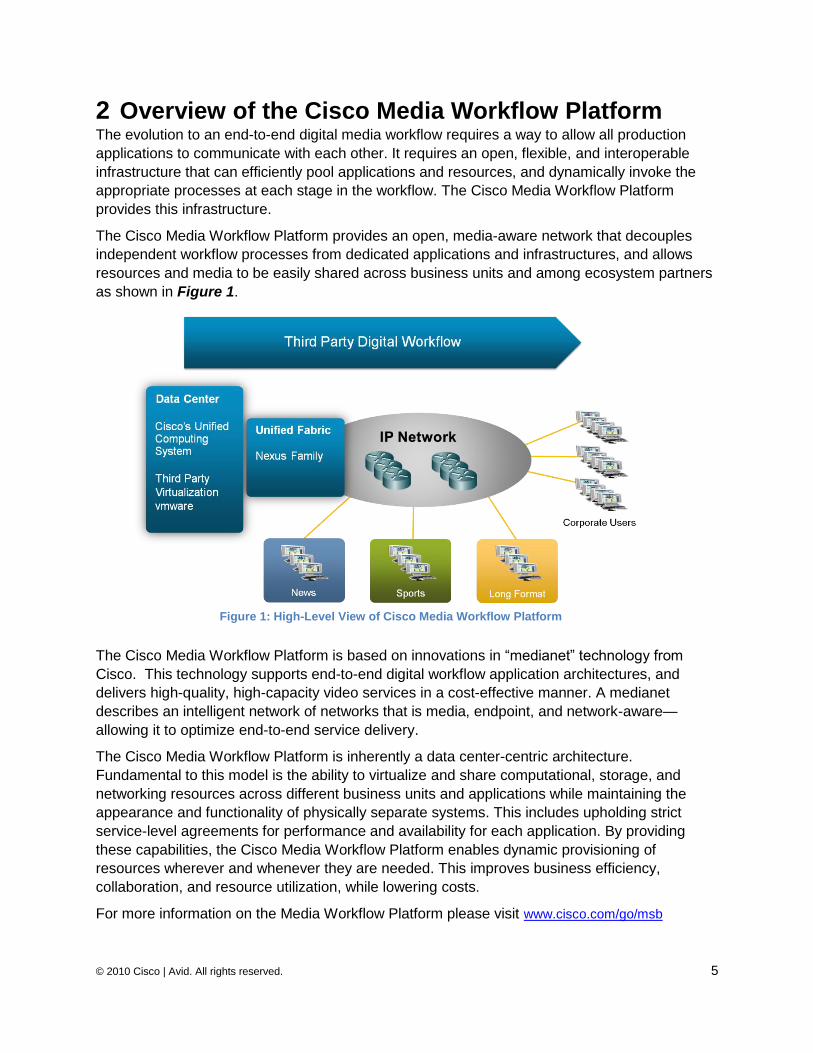
The Cisco Media Workflow Platform provides an open, media-aware network that decouples
independent workflow processes from dedicated applications and infrastructures, and allows
resources and media to be easily shared across business units and among ecosystem partners
as shown in Figure 1.
The Cisco Media Workflow Platform is based on innovations in ―medianet‖ technology from
Cisco. This technology supports end-to-end digital workflow application architectures, and
delivers high-quality, high-capacity video services in a cost-effective manner. A medianet
describes an intelligent network of networks that is media, endpoint, and network-aware—
allowing it to optimize end-to-end service delivery.
The Cisco Media Workflow Platform is inherently a data center-centric architecture.
Fundamental to this model is the ability to virtualize and share computational, storage, and
networking resources across different business units and applications while maintaining the
appearance and functionality of physically separate systems. This includes upholding strict
service-level agreements for performance and availability for each application. By providing
these capabilities, the Cisco Media Workflow Platform enables dynamic provisioning of
resources wherever and whenever they are needed. This improves business efficiency,
collaboration, and resource utilization, while lowering costs.
For more information on the Media Workflow Platform please visit www.cisco.com/go/msb
Figure 1: High-Level View of Cisco Media Workflow Platform
© 2010 Cisco | Avid. All rights reserved. 6
2.1 Evolution of Digital Workflows To understand the scope of the evolution from conventional workflows to the digital workflows
envisioned by the Cisco Media Workflow Platform, it is important to consider the entire
broadcasting production model—a model that encompasses end-to-end production processes
from idea conception to content publishing.
A typical media workflow may involve a range of departments and processes, including
processes that do not relate to handling video content. The evolution to a digital workflow
model—and the architecture employed—must account for the characteristics of these workflow
processes at each stage in the transition. This transition typically occurs in three stages:
Stage 1: The media company introduces IT applications in ‖silos‖(e.g., strictly for news). A
non-linear editing (NLE) application replaces legacy editing systems, video files replace
video tapes, and a collaborative storage solution allows all NLE clients to jointly work on
the same content. This initial stage of the evolution introduces fully digital workflows in
the production silo. However, communication with outside processes is still typically
handled via physical tapes.
Stage 2: Multiple production silos (e.g., long-form drama, and news) are connected via a
common content management system. This system is generally supported by the
introduction of a media asset management system and centralized content storage
system. In this environment, a common network supports movement of media among
the production processes. Depending on process implementation, it is generally based
on either a single network or set of interconnected networks.
Stage 3: In the first two stages of the digital workflow evolution, the media company still
treats the production environment separately from IT and the rest of the business
environment. While certain business applications (e.g., marketing, resource
management) may integrate with production applications, users generally must still be
physically located in the production network (or use a proxy that is physically connected
to the network) to access production resources. The third stage of the workflow evolution
eliminates this limitation and introduces new capabilities such as full user mobility and
company-wide collaborative workflows. To implement these new capabilities, IT and
production networks converge within a single environment. Now, production applications
are treated as any other application on the network, albeit while maintaining the strict
latency, quality, availability, and other requirements they demand. IT and production
engineers must find new ways to collaborate as the lines separating their areas of
responsibility blur.
A specific IT network design is required to achieve this third stage in the evolution to digital
workflows. The network must be able to support the enormous amount of video content involved
in post-production processes, along with business IT applications, while also meeting stringent
service-level delivery requirements. Such a network must provide:
Support for strict security, latency, and availability requirements
Tools to segregate resources over a converged network
The ability to function within the limitations of existing applications and business
processes
Technology innovations to enable new processes and applications
© 2010 Cisco | Avid. All rights reserved. 7
The following sections of this paper provide an overview of the characteristics of such a
network, and highlight Cisco‘s key architectural recommendations for supporting a media
production environment based on the Avid application suite and Avid Unity ISIS system.
2.2 Disclaimer The technical information contained in this document is provided 'as is' for best practices without
warranty of any kind. Please note that while Cisco believes that most of the technical
information, design architecture and recommendations contained in this paper can be
considered ‗current best practice‘, and represent the views of some of our top specialists,
specific recommendations must always be adapted to suit the specific needs of individual
environments.
At the time of publication most of the recommendations made here have not been fully tested
in real-world production environments. Several of these are still to be fully verified in a lab
environment and some of the platform recommendations have yet to be subjected to any
testing at all.
The approved designs available in the Avid Unity ISIS Ethernet Switch Reference Guide
(Section 7.1) represent simple contained solutions that can be deployed without the
involvement of Avid solutions. However the purpose of this document is to discuss deploying
complex solutions beyond the production environment. If you are deploying such a solution, it is
essential to work in partnership with an Avid Network Consultant to ensure your end-to-end
solution can be approved as suitable for delivery of ultra real-time video to editing workstations.
3 Enterprise Network Architecture for Avid Unity ISIS Systems
3.1 Introduction
Note: In the following content, the information related to Avid Unity Systems has been derived from the Avid white paper that describes the Network Requirements for Avid Unity ISIS and Interplay. This document has been written by David Shephard, European Consulting Engineer from Avid, based in UK.
An update (rel.1.61) of this Avid white paper is available at: Network Requirements for Avid Unity ISIS and Interplay and Avid Unity ISIS Ethernet Switch Reference Guide
As of 2010, Avid has the leading market share of Audio/Video Production and Newsroom
systems deployed in the Media Broadcast market. Their Avid Unity ISIS system is one of the
best reference systems for most broadcasters.
Avid Unity ISIS is an Advanced Storage Array supporting broadcaster applications required in a
media production environment such as Ingest, Rough Cut Editing, Audio/Video Editing,
Finishing, Transcoding and Playout. The different software components used in Production and
Post-production stages are detailed in Chapter 3.3.
© 2010 Cisco | Avid. All rights reserved. 8
Because all the storage (NAS) is contained in the network ISIS engine, only network traffic (IP
and L2) moves from the ISIS system to the media clients. Therefore the recommended and
validated design regarding the deployment for the Avid Unity ISIS system only concerns the IP
network, not the Fiber Channel network design.
To support Avid ISIS system applications (clients servers), the network infrastructure should
work with all other regular office applications (e.g., CRM/ERM, e-Business, IP Telephony or any
Unified communication tools). Combining these applications on the same network infrastructure
will increase design complexity.
The Avid ISIS client server applications require that latency must be as small as possible to
avoid any undesirable visual impact for editing functions (e.g., hangs of several seconds at the
editor desk). It is very important that all of the network components that carry video applications
from end-to-end inject a minimum of latency In & Out. Therefore most stateful devices such as
firewall, or Intrusion Prevention Systems must be avoided in the path between the servers and
the editing clients. Stateful devices include devices that inspect the pattern of the video streams
in order to police the flow. This is discussed in Chapter 3.4.1.
Avid has qualified and certified a limited number of Cisco switches which are described in
Section 3.4.1. This is in support of Media Application workflows which require very large buffer
sizes to handle concurrent communication from multiple server blades bursting to a single client.
This blueprint will evolve to include additional Cisco switches and Avid products and solutions
as products are tested. Deployments based on ―non-certified‖ network components and
architecture must be tested in a real-world production network prior to validating the Media
workflow platform solutions.
This blueprint provides additional recommendations on multiple network switches and
architecture to address large network infrastructures for broadcasters planning to deploy the
Avid ISIS solution. In addition, these recommendations include a forward view with regards to a
new generation of switches.
Several options are covered in this document, including improvement in high availability in
Zones 2 and 3. Zones are described in Section 3.4.1. Additional network architectures are
covered to ―improve‖ network design and High Availability on the global architecture of Zone 4
and to ease their integration into a single enterprise IP campus network.
Video flows used in the broadcaster production (especially for editing applications) are
described in this document as ―ultra real-time‖ video streams. The nature of these flows is
dramatically different from the distribution stage where compressed flows are conveyed by RTP
Real Time Protocol.
In Avid‘s environment, the flows between Editing stations and storage servers (ISIS) are
conveyed through a UDP block-based proprietary protocol. This proprietary protocol enables
journalists and editors to jog with the content (fast-forward, fast-rewind, stop, start, forward,
rewind, cut, paste), Such actions could not be implemented using a streaming protocol
such as RTP.
All of these actions, which stress and sometimes exhaust network resources, have driven us to
issue this document.
© 2010 Cisco | Avid. All rights reserved. 9
Network designs based on Data Center Bridging (IEEE DCB) and Fiber Channel over Ethernet
(FCoE) are not covered in this document.
3.2 Avid Unity ISIS Systems
3.2.1 ISIS Systems Overview
The Avid Unity ISIS is built upon the concept of ―Grid Storage‖. Grid storage provides an
architecture which is highly scalable and highly redundant. Avid has developed a 64 bit ―real
time‖ file system which is distributed across all the components of the ISIS system.
The Avid Unity ISIS Engine utilizes intelligent storage and network switch blades (2 per chassis)
which use standard Gigabit Ethernet interfaces connected inside the mid-plane. There are no
remote storage interfaces (such as FC or FCIP or iSCSI). The storage is all integrated into the
ISIS system, which is built like a blade chassis. It has 16 servers (ISIS Storage Blade - ISB) per
enclosure. Each supports two hard drives (1TBytes, 500 GBytes fully mirrored with ISIS 1.x -
doubled to 2TBytes, 1TByte fully mirrored with ISIS 2.0) to provide a total storage capacity of
16TBytes per enclosure.
All Servers are dual-homed to two separate switch blades (ISIS Integrated Switch – ISS), via
the mid-plane, using 1GE Ethernet access. A complete Avid Unity ISIS system is able to
support up to 12 enclosures interconnected using proprietary 12Gbps links. This large system
can bring total consolidated storage capacity to 384TB (192TBytes, fully mirrored or 288TBytes
with RAID 6 protection) with ISIS 2.1.
Hardware details are covered in Chapter 3.3. You may also download a ReadMe document
about the Avid Unity ISIS system at the end of this white paper in Chapter 6.1.3. The document
provides hardware and software requirements, a hardware overview, and other important
information.
High resolution video on the ISIS application implies high performances on the network
infrastructure without any single point of congestion. To ensure the best quality performance for
the editing application, Avid ISIS v2.0 communicates to the editors using blocks of 256 Kbyte
(ISIS 1.x) or 512 Kbyte bursts (default) of UDP.
The media flows exchanged between the servers and the clients are fundamentally different
than standard FTP transfers, as they are block-based and not file-based. An editing client
application that requests a certain series of UDP blocks, can only request the next block if it has
fully received the previous block. Application response time is conditioned by how long the
complete block needs to travel through the network. Therefore, speed, latency, packet memory
capacity and the lossless nature of data for ISIS traffic are extremely important for efficiency.
The larger the UDP burst from the NAS (ISIS engine), the faster the delivery of the media flow.
However, this assumes there is no packet loss and enough packet memory capacity along the
path between the server and the client. Otherwise efficiency will drop very quickly.
The read-window size and required data rate is dependent on the video resolution selected and
the number of streams requested. The following chapters will focus on this behavior that is
specific to Avid ISIS workflows.
© 2010 Cisco | Avid. All rights reserved. 10
3.2.2 Avid & Media Workflows Platform
Avid delivers a full suite of applications aimed at supporting the digital of post-production
processes in a media broadcaster environment. The company also supports the digital of
Newsroom processes.
From a network design perspective, all these applications pertain to a specific ―Zone‖.
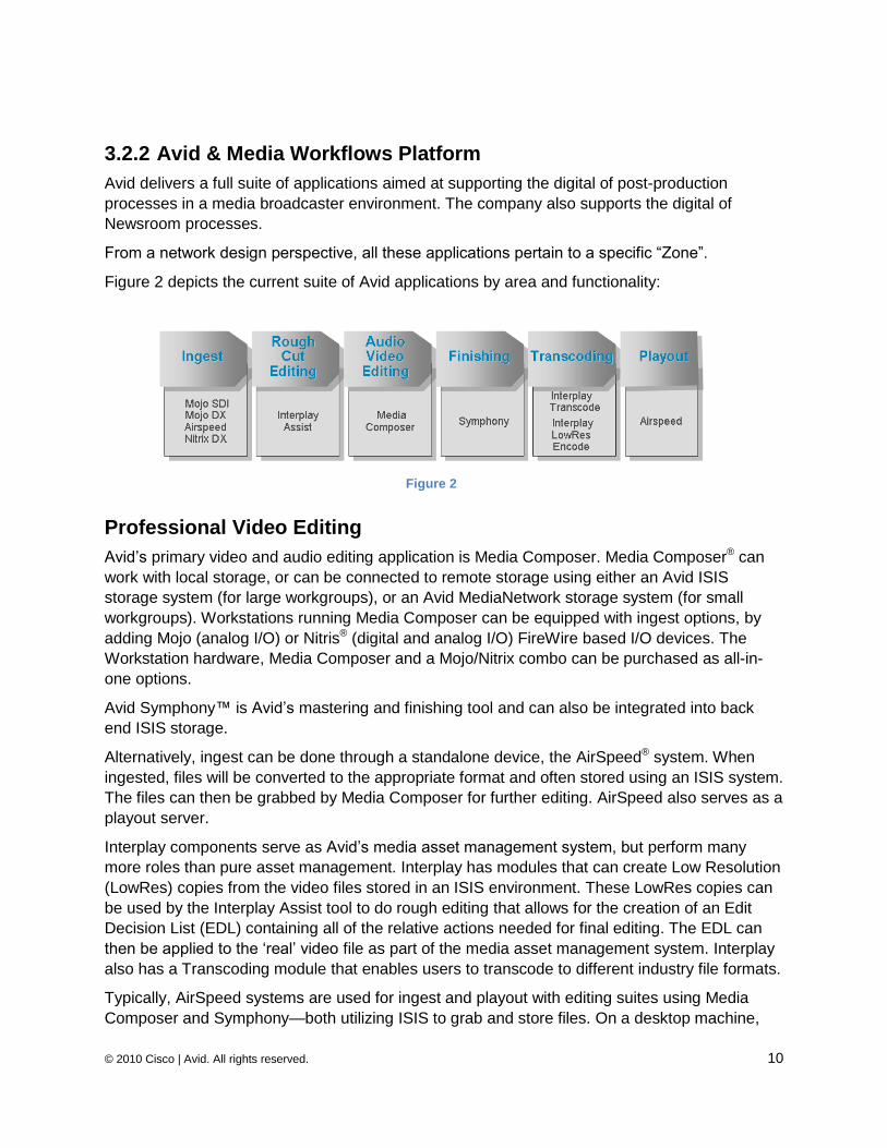
Figure 2 depicts the current suite of Avid applications by area and functionality:
3.2.2.1 Professional Video Editing
Avid‘s primary video and audio editing application is Media Composer. Media Composer® can
work with local storage, or can be connected to remote storage using either an Avid ISIS
storage system (for large workgroups), or an Avid MediaNetwork storage system (for small
workgroups). Workstations running Media Composer can be equipped with ingest options, by
adding Mojo (analog I/O) or Nitris® (digital and analog I/O) FireWire based I/O devices. The
Workstation hardware, Media Composer and a Mojo/Nitrix combo can be purchased as all-in-
one options.
Avid Symphony™ is Avid‘s mastering and finishing tool and can also be integrated into back
end ISIS storage.
Alternatively, ingest can be done through a standalone device, the AirSpeed® system. When
ingested, files will be converted to the appropriate format and often stored using an ISIS system.
The files can then be grabbed by Media Composer for further editing. AirSpeed also serves as a
playout server.
Interplay components serve as Avid‘s media asset management system, but perform many
more roles than pure asset management. Interplay has modules that can create Low Resolution
(LowRes) copies from the video files stored in an ISIS environment. These LowRes copies can
be used by the Interplay Assist tool to do rough editing that allows for the creation of an Edit
Decision List (EDL) containing all of the relative actions needed for final editing. The EDL can
then be applied to the ‗real‘ video file as part of the media asset management system. Interplay
also has a Transcoding module that enables users to transcode to different industry file formats.
Typically, AirSpeed systems are used for ingest and playout with editing suites using Media
Composer and Symphony—both utilizing ISIS to grab and store files. On a desktop machine,
Figure 2
© 2010 Cisco | Avid. All rights reserved. 11
Interplay Assist can be used to fetch LowRes copies—again using ISIS. Other Interplay tools for
file conversion, etc., also use ISIS. Essentially the entire workflow is based on different fetches
and stores using the UDP-based ISIS system. There are some other TCP-based control
connections between various parts of the system, but they are not as traffic-intensive as the
ISIS.
3.2.2.2 News Room NewsCutter Software
Designed for broadcast news editing, Avid NewsCutter® video editing software gives journalists
all the tools they need to produce news on their own while in the field or in the newsroom.
NewsCutter also provides tight integration with newsroom automation systems like iNEWS®,
playout servers, and collaborative workflows.
Media Management
In an Avid solution, all Media Asset Management capabilities are centralized under the umbrella
of the following suite of Interplay products.
Interplay Access
Interplay Media DB
Interplay Transfer
Interplay Archive™
Newsroom computer system (NRCS): iNEWS
iNEWS® is a central tool for Journalists. The Avid iNEWS newsroom computer system (NRCS)
provides journalists with all the tools necessary to plan, create, publish, and archive a news
broadcast.
Avid iNEWS NRCS is scalable for ten to thousands of users working across multiple sites. It
brings the newsroom system, editing systems, and playout applications together in a unified
production environment.
Starting with wire service ingest and wire search capabilities, and continuing through
assignment desk, story research, and newsroom communication management, news
professionals and managers are keyed directly into the system from their desktops.
iNEWS adds support for Avid iNEWS Instinct®, an application that provides journalists with
visual storytelling capabilities on their desktop in a familiar script-based format.
The Avid iNEWS Web Client is a browser-based, simplified front-end to the NRCS that allows
journalists to create and modify stories quickly from any location.
Journalist Editor: iNEWS Instinct
Avid iNEWS Instinct brings together script writing, shot selection, editing, voiceover recording,
and split-audio editing in a tool that is specifically tailored to the journalist. A unique new
interface, combined with a workflow that follows the logic of news writing, means that any
producer, writer, or journalist can add to the production process.
Please see the reference section at the end of Section 7.1.2 of this document for more
information.
© 2010 Cisco | Avid. All rights reserved. 12
3.2.2.3 ISIS Client Performance Testing Avid ISIS clients have the option of using Avid‘s PathDiag tool to run performance tests on their
connections from their workstations. PathDiag offers the ability to emulate the editor application
by transferring data using different video resolutions (Avid DNxHD®, DV/IMX, MPG-2). It is
therefore able to validate how many video streams can be edited with specific resolutions.
A separate white paper is available on Avid.com for more details on the Avid ISIS client
performance test. Please see Section 7.1.3 in the reference section of this document for more
information
3.3 Avid ISIS Media Network Environment The Avid Unity ISIS system enables multiple clients to capture, play, and edit video and audio media. This chapter provides an overview of the Avid Unity ISIS system and the basic function of each Avid hardware component within the system.
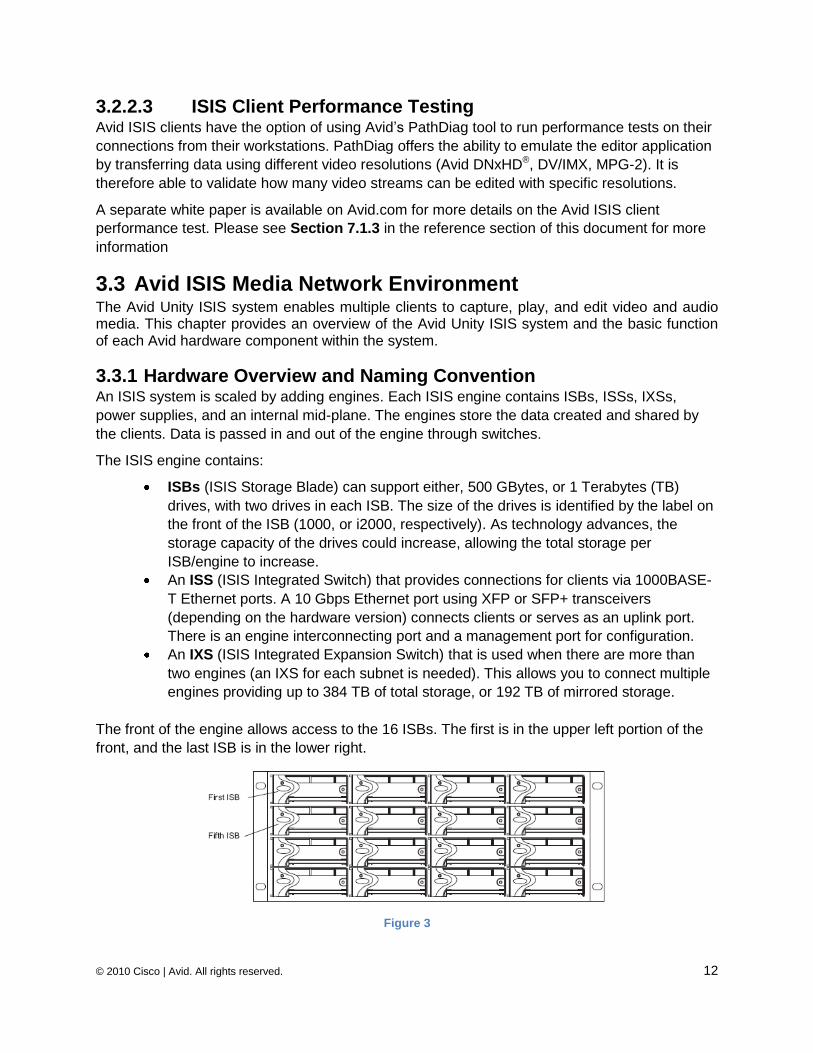
3.3.1 Hardware Overview and Naming Convention An ISIS system is scaled by adding engines. Each ISIS engine contains ISBs, ISSs, IXSs,
power supplies, and an internal mid-plane. The engines store the data created and shared by
the clients. Data is passed in and out of the engine through switches.
The ISIS engine contains:
ISBs (ISIS Storage Blade) can support either, 500 GBytes, or 1 Terabytes (TB)
drives, with two drives in each ISB. The size of the drives is identified by the label on
the front of the ISB (1000, or i2000, respectively). As technology advances, the
storage capacity of the drives could increase, allowing the total storage per
ISB/engine to increase.
An ISS (ISIS Integrated Switch) that provides connections for clients via 1000BASE-
T Ethernet ports. A 10 Gbps Ethernet port using XFP or SFP+ transceivers
(depending on the hardware version) connects clients or serves as an uplink port.
There is an engine interconnecting port and a management port for configuration.
An IXS (ISIS Integrated Expansion Switch) that is used when there are more than
two engines (an IXS for each subnet is needed). This allows you to connect multiple
engines providing up to 384 TB of total storage, or 192 TB of mirrored storage.
The front of the engine allows access to the 16 ISBs. The first is in the upper left portion of the
front, and the last ISB is in the lower right.
Figure 3
© 2010 Cisco | Avid. All rights reserved. 13
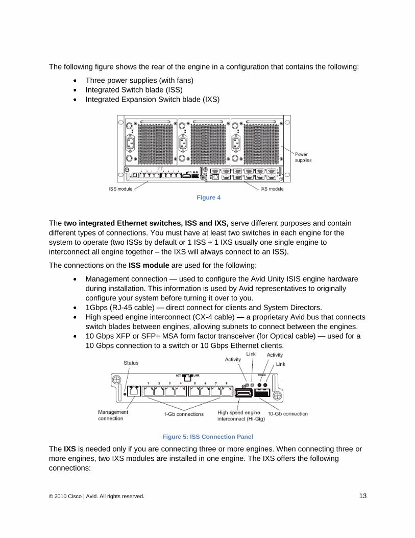
The following figure shows the rear of the engine in a configuration that contains the following:
Three power supplies (with fans)
Integrated Switch blade (ISS)
Integrated Expansion Switch blade (IXS)
The two integrated Ethernet switches, ISS and IXS, serve different purposes and contain
different types of connections. You must have at least two switches in each engine for the
system to operate (two ISSs by default or 1 ISS + 1 IXS usually one single engine to
interconnect all engine together – the IXS will always connect to an ISS).
The connections on the ISS module are used for the following:
Management connection — used to configure the Avid Unity ISIS engine hardware
during installation. This information is used by Avid representatives to originally
configure your system before turning it over to you.
1Gbps (RJ-45 cable) — direct connect for clients and System Directors.
High speed engine interconnect (CX-4 cable) — a proprietary Avid bus that connects
switch blades between engines, allowing subnets to connect between the engines.
10 Gbps XFP or SFP+ MSA form factor transceiver (for Optical cable) — used for a
10 Gbps connection to a switch or 10 Gbps Ethernet clients.
Figure 5: ISS Connection Panel
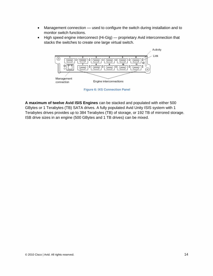
The IXS is needed only if you are connecting three or more engines. When connecting three or
more engines, two IXS modules are installed in one engine. The IXS offers the following
connections:
Figure 4
© 2010 Cisco | Avid. All rights reserved. 14
Management connection — used to configure the switch during installation and to
monitor switch functions.
High speed engine interconnect (Hi-Gig) — proprietary Avid interconnection that
stacks the switches to create one large virtual switch.
A maximum of twelve Avid ISIS Engines can be stacked and populated with either 500
GBytes or 1 Terabytes (TB) SATA drives. A fully populated Avid Unity ISIS system with 1
Terabytes drives provides up to 384 Terabytes (TB) of storage, or 192 TB of mirrored storage.
ISB drive sizes in an engine (500 GBytes and 1 TB drives) can be mixed.
Figure 6: IXS Connection Panel
© 2010 Cisco | Avid. All rights reserved. 15
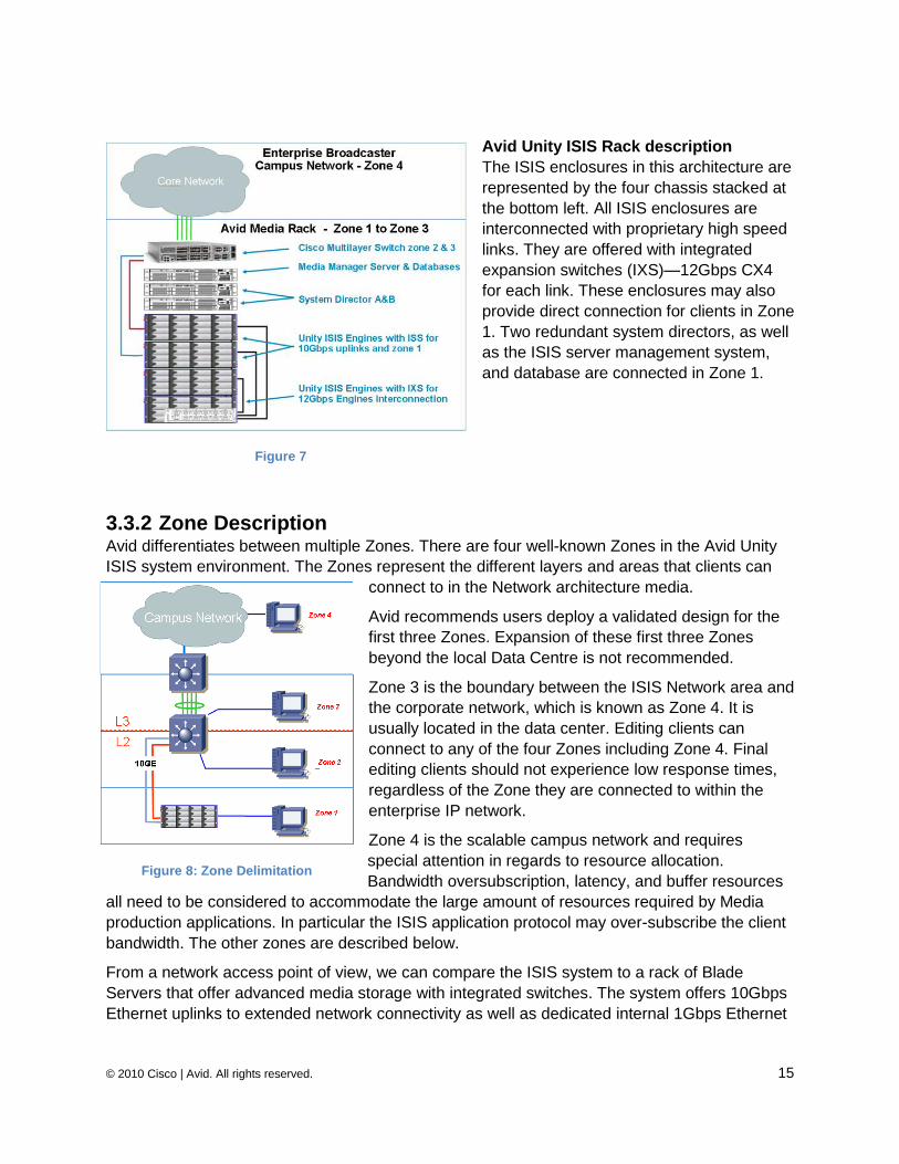
Avid Unity ISIS Rack description
The ISIS enclosures in this architecture are
represented by the four chassis stacked at
the bottom left. All ISIS enclosures are
interconnected with proprietary high speed
links. They are offered with integrated
expansion switches (IXS)—12Gbps CX4
for each link. These enclosures may also
provide direct connection for clients in Zone
1. Two redundant system directors, as well
as the ISIS server management system,
and database are connected in Zone 1.
3.3.2 Zone Description Avid differentiates between multiple Zones. There are four well-known Zones in the Avid Unity
ISIS system environment. The Zones represent the different layers and areas that clients can
connect to in the Network architecture media.
Avid recommends users deploy a validated design for the
first three Zones. Expansion of these first three Zones
beyond the local Data Centre is not recommended.
Zone 3 is the boundary between the ISIS Network area and
the corporate network, which is known as Zone 4. It is
usually located in the data center. Editing clients can
connect to any of the four Zones including Zone 4. Final
editing clients should not experience low response times,
regardless of the Zone they are connected to within the
enterprise IP network.
Zone 4 is the scalable campus network and requires
special attention in regards to resource allocation.
Bandwidth oversubscription, latency, and buffer resources
all need to be considered to accommodate the large amount of resources required by Media
production applications. In particular the ISIS application protocol may over-subscribe the client
bandwidth. The other zones are described below.
From a network access point of view, we can compare the ISIS system to a rack of Blade
Servers that offer advanced media storage with integrated switches. The system offers 10Gbps
Ethernet uplinks to extended network connectivity as well as dedicated internal 1Gbps Ethernet
Figure 7
Figure 8: Zone Delimitation
© 2010 Cisco | Avid. All rights reserved. 16
interfaces for local ISIS clients (via the mid-plane). The main difference from a regular network
infrastructure resides on the storage side which is fully embedded inside the ISIS Systems.
It is important to respect the order interconnecting different Zones. This is a hop-based daisy-
chain, where Zone 1 can border only Zone 2 (one Layer 2 hop), which can only border Zone 3
(one Layer 3 hop max). This pattern continues from Zone 3 to Zone 4 (multiple Layer 3 hops).
In an ISIS Media Network, you can set your client type to one of the following levels, depending
on your bandwidth requirements:
Ultra High Resolution — this setting is for Avid editing systems with 10 Gbps
Ethernet connections supporting clients editing in Uncompressed HD and multiple
Avid DNxHD/SD stream counts. These specific editors are also known as Craft
Editors. These ultra high-resolution clients (UHRC) only access the media network in
Zone 1, Zone 2, or Zone 3. Access beyond these zones may work in particular
network designs, but is not supported at this time.
High Resolution — this setting is intended for Avid editing systems or Avid Interplay
Assist using Avid DNxHD resolutions like Avid DNxHD 145/120 or DV50/IMX-50. In
addition to higher bandwidth allocations, High Resolution clients have shorter time-
out values. These editors can sit in Zone 4, the enterprise network. Therefore, the
end-to-end campus network must be dimensioned according to the number of
editors. Alternatively, they can be located in a dedicated editing room connected to
Zone 1 and to Zone 3.
Medium Resolution — this setting is intended for Avid editing systems using
DV25/IMX30 in Zone 1 to Zone 4. At the time of publishing, this is the default client
type setting.
Low Resolution — This setting is intended for Avid editing systems using MPEG-2
in Zone 4. The Avid Unity ISIS system assigns this client type an oversubscription
shut off and smaller read/write sizes.
The iNEWS and Interplay Assist Media Clients can work in any of the four Zones, as long as the
end-to-end oversubscription and buffer resources are provisioned according to the number of
editing clients and the number and definitions of the video streams are initialized across all
Zones.
Zone-1
– Connected to ISIS VLAN(s) via Gbps Port (direct connect)
Clients in Zone 1 are directly connected to the ISIS system which includes two embedded
switch blades (ISS). This offers a total of 2 x 8 Gigabit BaseT interfaces per enclosure. If more
than two ISIS engines are to be interconnected, one of the ISIS engines from the stack will be
built with two IXS modules used for global ISIS engine interconnection. Theoretically this could
support up to 176 (11 engines with 16 gigabit interfaces on each) local clients in a full system
(maximum of 12 enclosures interconnected using Avid proprietary 12Gbps fibers (IXS that uses
the network slots on the first engine).
The mid-plane interconnection between the storage servers (also known as ISB) and the
embedded switch (ISS) is ―hardcoded‖.
© 2010 Cisco | Avid. All rights reserved. 17
Zone-2
– Connected to ISIS VLAN(s) via 1Gbps port or 10Gbps port on (10Gbps connected) Avid
qualified Switch L2
Clients in Zone 2 are connected to a dedicated standalone switch which is normally validated or
approved by Avid. This switch extends the layer 2 broadcast domain of Zone 1 which is used to
connect local ISIS Application clients. Only the 4948-10GE and 4900-M Cisco switches are
validated models as of today. Other switch models, such as Cisco Catalyst® 6500, can be
deployed following the recommendations described in Section 3.4.1.
The switch in Zone 2 is dual-homed from the Avid ISIS system (Zone 1) using 2 x 10GE uplinks.
It is important to note that:
1. Each Uplink uses a different VLAN (VLAN10 & VLAN20) coming from different switch blades. Therefore, there is no possible L2 loop as long as the embedded switches are not connected together.
2. STP does not run on the ISIS system. The system forwards the BPDUs. Therefore, even
if there is a mis-configuration with multiple enclosures and multiple uplinks, the upstream
switch will block the redundant paths. Zone 2 is a pure L2 broadcast domain, so no
routing is allowed there.
Zone-3
– Connected to an Avid Qualified Layer-3 Switch (Router) with known QoS (normally 1Gbps)
– Traffic routed to ISIS (1 hop) and load balanced across ISIS Vlan (~60/40 ratio)
Clients in Zone 3 are connected to the same Switch used for Zone 2. However, routed VLANs
are used for those clients to access the ISIS system. There is no impact in terms of
performance or latency as Layer 3 switching is performed in hardware.
Zone-4
– Connected to Customer‘s Edge/Core switch with unknown QoS
– Traffic routed to ISIS and load balance traffic across ISIS Vlan (~60/40 ratio)
Finally, editing clients can be connected on any access port (wiring closet port) within the
campus IP network, which forms Zone 4. It should be possible to connect an editing workstation
anywhere in the Enterprise network. This allows for multi-stream DV50 (or higher) editing as
long as all network requirements are addressed. However, it is much more difficult to address
bandwidth, buffer and latency requirements in Zone 4 than in other Zones. This is due to its
complexity, shared infrastructure and scalability requirements.
The Corporate network is the most complex and sensitive Zone as media flows must cohabit
with other critical business application flows such as SAP, Oracle, VoIP, etc. Network paths and
switches must be configured according to the media flow requirements (bandwidth, buffer size,
oversubscription, latency).
Sufficient Network resources must be available from end-to-end. QoS techniques may need to
be used to ensure sufficient network resource availability. When required the QoS must provide
a granular configuration according to all critical and sensitive applications that impose high
© 2010 Cisco | Avid. All rights reserved. 18
bandwidth and low latency especially when used for high resolution video editing. QoS is
covered in Chapter 3.5.
A network design ―upgrade‖ is necessary to support a production network infrastructure where
media workflow is run in conjunction with existing applications and services. Such a network will
need higher bandwidth, as well as some additional network components for better utilization of
buffer resources.
This is discussed in Section 3.4.4.
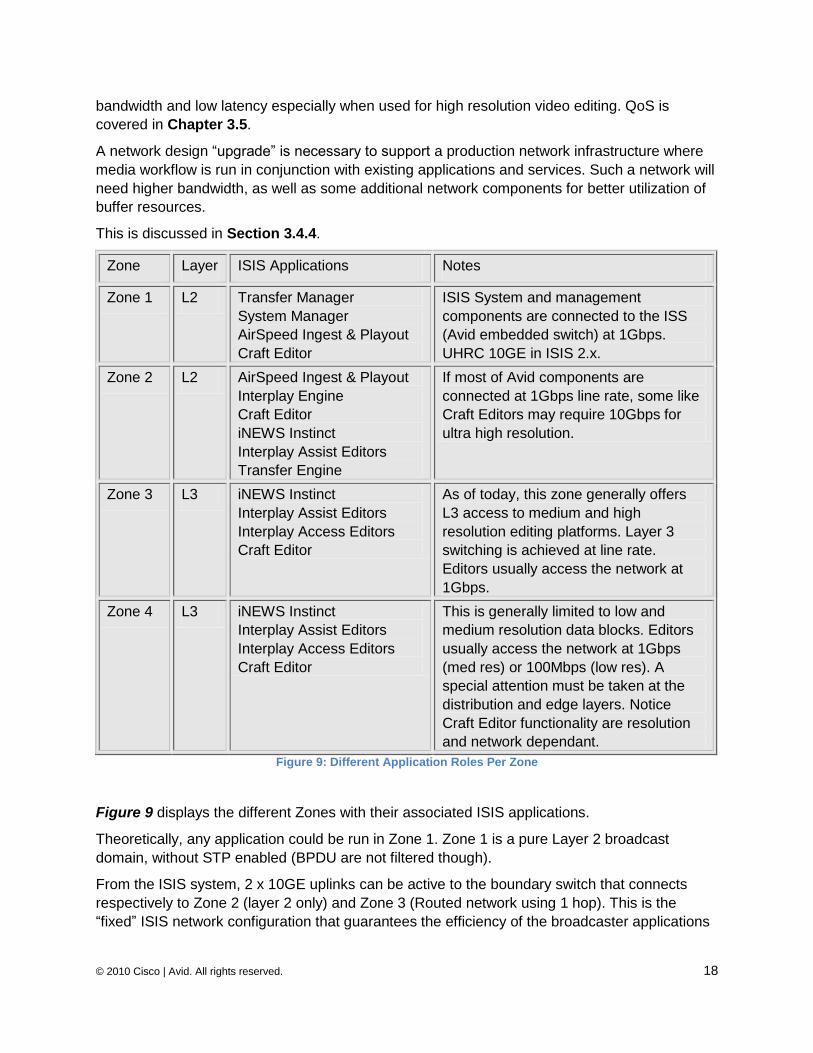
Zone Layer ISIS Applications Notes
Zone 1 L2 Transfer Manager
System Manager
AirSpeed Ingest & Playout
Craft Editor
ISIS System and management
components are connected to the ISS
(Avid embedded switch) at 1Gbps.
UHRC 10GE in ISIS 2.x.
Zone 2 L2 AirSpeed Ingest & Playout
Interplay Engine
Craft Editor
iNEWS Instinct
Interplay Assist Editors
Transfer Engine
If most of Avid components are
connected at 1Gbps line rate, some like
Craft Editors may require 10Gbps for
ultra high resolution.
Zone 3 L3 iNEWS Instinct
Interplay Assist Editors
Interplay Access Editors
Craft Editor
As of today, this zone generally offers
L3 access to medium and high
resolution editing platforms. Layer 3
switching is achieved at line rate.
Editors usually access the network at
1Gbps.
Zone 4 L3 iNEWS Instinct
Interplay Assist Editors
Interplay Access Editors
Craft Editor
This is generally limited to low and
medium resolution data blocks. Editors
usually access the network at 1Gbps
(med res) or 100Mbps (low res). A
special attention must be taken at the
distribution and edge layers. Notice
Craft Editor functionality are resolution
and network dependant.
Figure 9: Different Application Roles Per Zone
Figure 9 displays the different Zones with their associated ISIS applications.
Theoretically, any application could be run in Zone 1. Zone 1 is a pure Layer 2 broadcast
domain, without STP enabled (BPDU are not filtered though).
From the ISIS system, 2 x 10GE uplinks can be active to the boundary switch that connects
respectively to Zone 2 (layer 2 only) and Zone 3 (Routed network using 1 hop). This is the
―fixed‖ ISIS network configuration that guarantees the efficiency of the broadcaster applications
© 2010 Cisco | Avid. All rights reserved. 19
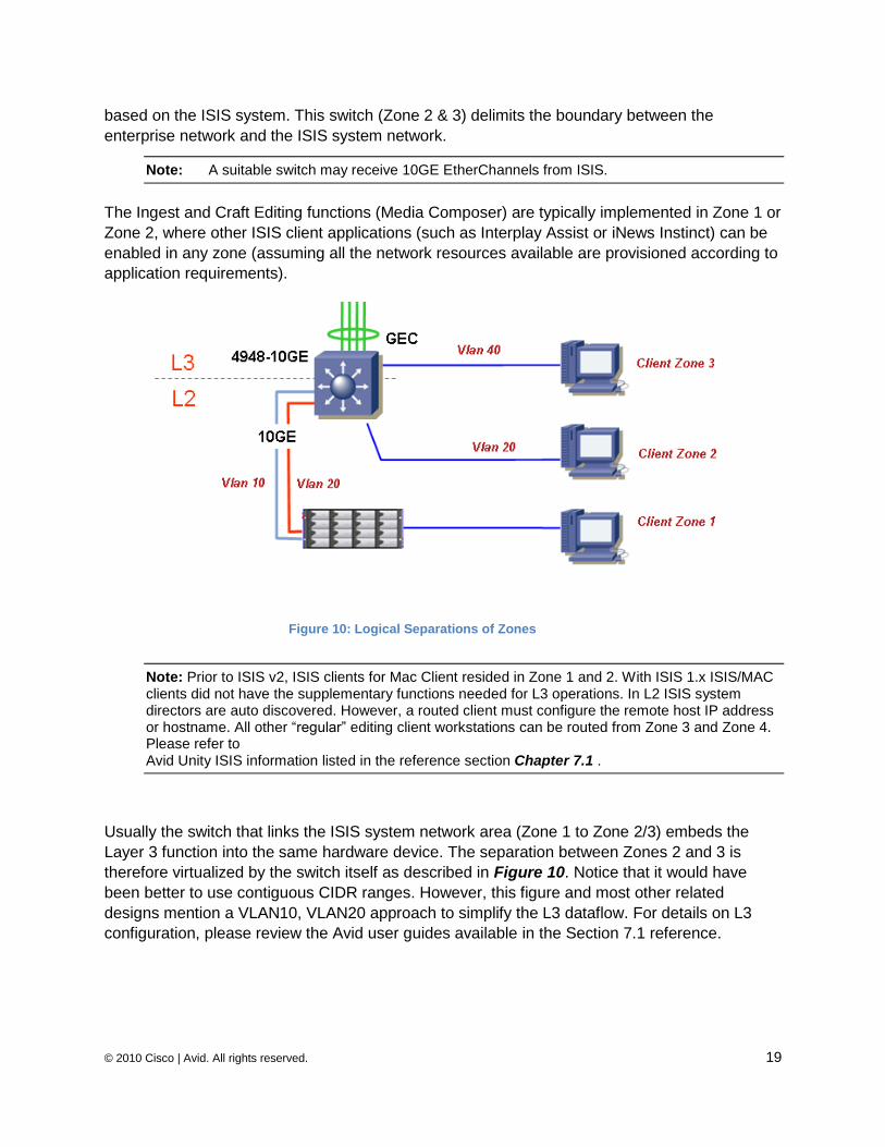
based on the ISIS system. This switch (Zone 2 & 3) delimits the boundary between the
enterprise network and the ISIS system network.
Note: A suitable switch may receive 10GE EtherChannels from ISIS.
The Ingest and Craft Editing functions (Media Composer) are typically implemented in Zone 1 or
Zone 2, where other ISIS client applications (such as Interplay Assist or iNews Instinct) can be
enabled in any zone (assuming all the network resources available are provisioned according to
application requirements).
Note: Prior to ISIS v2, ISIS clients for Mac Client resided in Zone 1 and 2. With ISIS 1.x ISIS/MAC clients did not have the supplementary functions needed for L3 operations. In L2 ISIS system directors are auto discovered. However, a routed client must configure the remote host IP address or hostname. All other ―regular‖ editing client workstations can be routed from Zone 3 and Zone 4. Please refer to Avid Unity ISIS information listed in the reference section Chapter 7.1 .
Usually the switch that links the ISIS system network area (Zone 1 to Zone 2/3) embeds the
Layer 3 function into the same hardware device. The separation between Zones 2 and 3 is
therefore virtualized by the switch itself as described in Figure 10. Notice that it would have
been better to use contiguous CIDR ranges. However, this figure and most other related
designs mention a VLAN10, VLAN20 approach to simplify the L3 dataflow. For details on L3
configuration, please review the Avid user guides available in the Section 7.1 reference.
Figure 10: Logical Separations of Zones
© 2010 Cisco | Avid. All rights reserved. 20
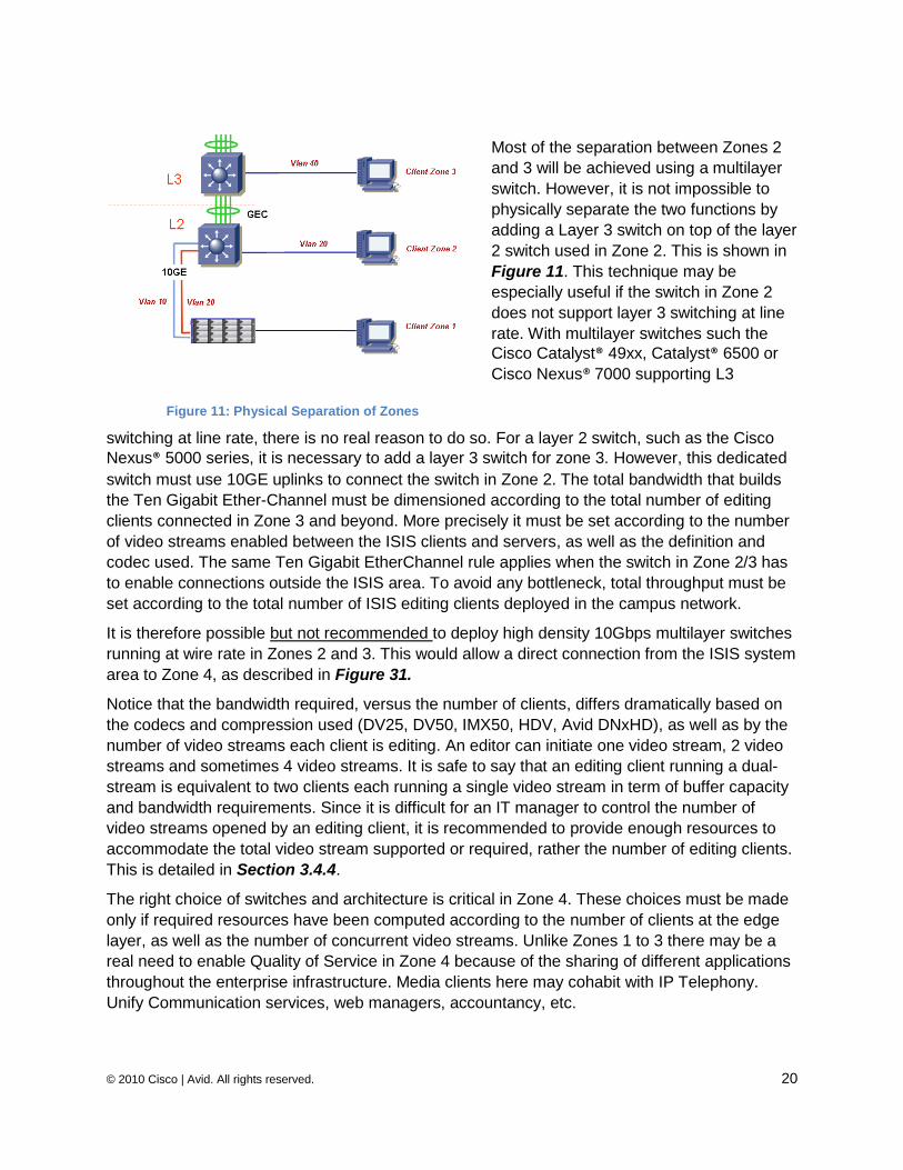
Most of the separation between Zones 2
and 3 will be achieved using a multilayer
switch. However, it is not impossible to
physically separate the two functions by
adding a Layer 3 switch on top of the layer
2 switch used in Zone 2. This is shown in
Figure 11. This technique may be
especially useful if the switch in Zone 2
does not support layer 3 switching at line
rate. With multilayer switches such the
Cisco Catalyst® 49xx, Catalyst® 6500 or
Cisco Nexus® 7000 supporting L3
switching at line rate, there is no real reason to do so. For a layer 2 switch, such as the Cisco
Nexus® 5000 series, it is necessary to add a layer 3 switch for zone 3. However, this dedicated
switch must use 10GE uplinks to connect the switch in Zone 2. The total bandwidth that builds
the Ten Gigabit Ether-Channel must be dimensioned according to the total number of editing
clients connected in Zone 3 and beyond. More precisely it must be set according to the number
of video streams enabled between the ISIS clients and servers, as well as the definition and
codec used. The same Ten Gigabit EtherChannel rule applies when the switch in Zone 2/3 has
to enable connections outside the ISIS area. To avoid any bottleneck, total throughput must be
set according to the total number of ISIS editing clients deployed in the campus network.
It is therefore possible but not recommended to deploy high density 10Gbps multilayer switches
running at wire rate in Zones 2 and 3. This would allow a direct connection from the ISIS system
area to Zone 4, as described in Figure 31.
Notice that the bandwidth required, versus the number of clients, differs dramatically based on
the codecs and compression used (DV25, DV50, IMX50, HDV, Avid DNxHD), as well as by the
number of video streams each client is editing. An editor can initiate one video stream, 2 video
streams and sometimes 4 video streams. It is safe to say that an editing client running a dual-
stream is equivalent to two clients each running a single video stream in term of buffer capacity
and bandwidth requirements. Since it is difficult for an IT manager to control the number of
video streams opened by an editing client, it is recommended to provide enough resources to
accommodate the total video stream supported or required, rather the number of editing clients.
This is detailed in Section 3.4.4.
The right choice of switches and architecture is critical in Zone 4. These choices must be made
only if required resources have been computed according to the number of clients at the edge
layer, as well as the number of concurrent video streams. Unlike Zones 1 to 3 there may be a
real need to enable Quality of Service in Zone 4 because of the sharing of different applications
throughout the enterprise infrastructure. Media clients here may cohabit with IP Telephony.
Unify Communication services, web managers, accountancy, etc.
Figure 11: Physical Separation of Zones
© 2010 Cisco | Avid. All rights reserved. 21
An IT manager may decide to enable editing clients running high resolution only in Zones 1 and
2 for highest performance, and select Zone 4 for lower resolution clients (typically MPEG-2).
This decision may be driven by design, oversubscription, and switch capacity used in Zone 4,
which may or may not be able to support multiple clients running the editing applications
concurrently within the same wiring closet.
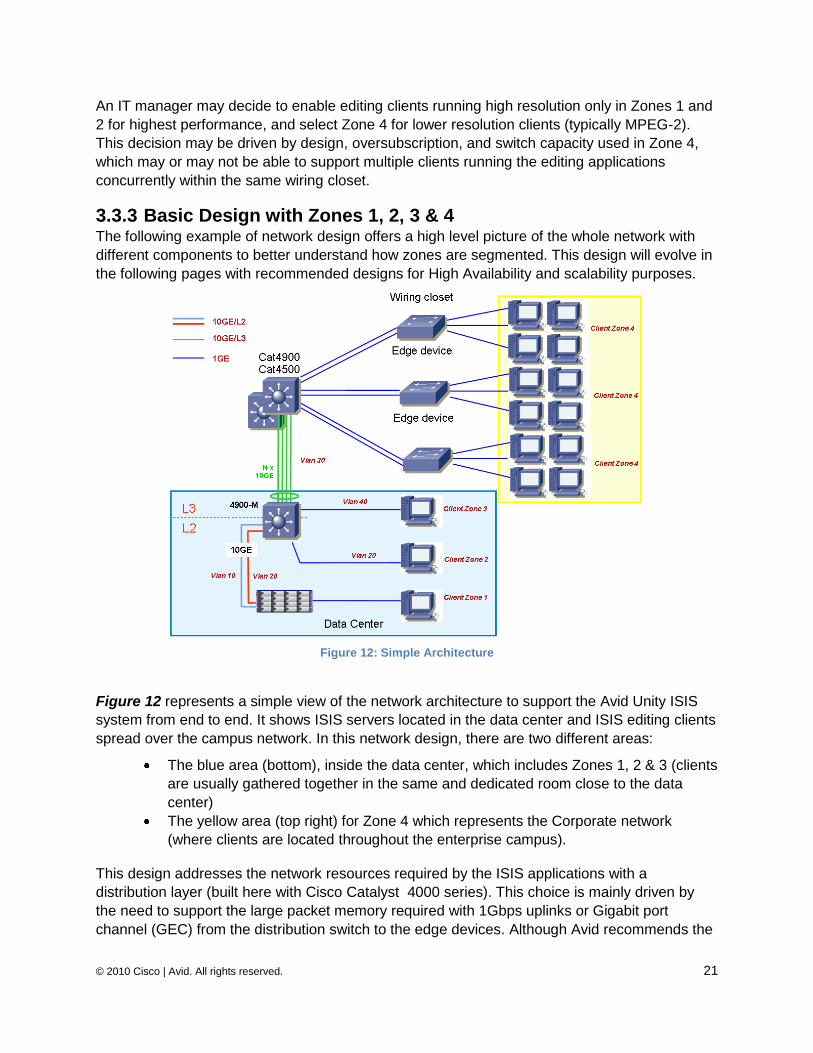
3.3.3 Basic Design with Zones 1, 2, 3 & 4 The following example of network design offers a high level picture of the whole network with
different components to better understand how zones are segmented. This design will evolve in
the following pages with recommended designs for High Availability and scalability purposes.
Figure 12: Simple Architecture
Figure 12 represents a simple view of the network architecture to support the Avid Unity ISIS
system from end to end. It shows ISIS servers located in the data center and ISIS editing clients
spread over the campus network. In this network design, there are two different areas:
The blue area (bottom), inside the data center, which includes Zones 1, 2 & 3 (clients
are usually gathered together in the same and dedicated room close to the data
center)
The yellow area (top right) for Zone 4 which represents the Corporate network
(where clients are located throughout the enterprise campus).
This design addresses the network resources required by the ISIS applications with a
distribution layer (built here with Cisco Catalyst 4000 series). This choice is mainly driven by
the need to support the large packet memory required with 1Gbps uplinks or Gigabit port
channel (GEC) from the distribution switch to the edge devices. Although Avid recommends the
© 2010 Cisco | Avid. All rights reserved. 22
use of qualified border switches in Zones 2/3, it is possible to build Zones 2/3 with other Cisco
switches, as long as network resources are not impacted.
HA technologies and bandwidth optimization can be improved with new generation switches
and technologies, such as VSS (Cisco Catalyst 6500) or vPC (Cisco Nexus 7000). In some
cases the N5k can be deployed for Zone 2. This is especially recommended when connecting
high-end ISIS engines for a large number of editors, and offering direct access to ultra high
resolution editing clients (Craft Editors) using 10GE NIC card on Zone 2. Notice that there are
not many editing clients in Media production today that run with 10GE NIC cards. However, we
expect to see an increased demand for such performance I/O starting in 2010. Additional details
are covered in Section 3.4.2.
In Figure 12, Zone 4 is schematically represented by a Cisco Catalyst 4000 series enabled as a
Distribution switch. The reason for deploying a Cisco Catalyst 4500 in the enterprise core (Zone
4) is detailed in Chapter 3.4. In short, the distribution switch must be able to support shared
1Gbps downlinks to connect to the edge layer switches. The Cisco Catalyst 4000 series
provides excellent dynamic buffer resource capacity. This is important to take into consideration
when switches are cascaded using 1Gbps uplinks or GEC to support multiple video streams
sharing the same uplink interfaces because the ISIS systems may offer multiple 10Gbps of
outbound throughput. When 1Gbps ―cascaded‖ switches are deployed for multiple shared video
streams, buffer resources must be dimensioned accordingly on the shared egress interface on
the aggregation layer interconnecting the edge devices.
In the Figure 12 example the edge devices are ―cascaded‖ to the Cisco Catalyst 4000 series
using 2 x 1Gbps uplinks. This means that each Port Channel interface on the Cisco Catalyst
4000 supporting the cascaded access switches needs to support the total amount of buffer
capacity required for all clients connected to the access switch. Assuming each client works with
media flows made of 256 Kbytes bursts (aka Craft Editors), 10 editing clients would required
2.5MBytes of buffer resources from the egress interface of the Cisco Catalyst 4500. Notice that
if the media applications use the default chunk of ISIS version 2.0 (512Kbyte), the total amount
of packet memory required at the egress interface would be 5Mbytes. Hence the total amount of
buffers per upstream 1Gbps interface must be sized according to the total burst required of all
clients (per single access switch). With uplinks built with GEC the Cisco Catalyst 4000 series
(Sup5-10GE and Sup6 including 49xx series) can be scaled with this cascaded configuration
(1Gbps-based uplinks) for a large number of editing clients. This is because the buffer memory
resources are dynamically shared between all interfaces (up to 17.5MB with the Cisco Catalyst
4900-M and Sup6).
Although the Cisco Catalyst 6500/6748 architecture has a larger total buffer memory resource
capacity (1.2Mbytes/Port) per interface than a Cisco Catalyst 4000 series, the buffer pool is
assigned and limited to each individual port. Therefore, contrary to the Cisco Catalyst 4000
series, unused buffer memory on one port cannot be dynamically allocated to another port
which would require more than its hardcoded assignment. Each assigned buffer resource per
port may not be sufficient to support several editors through the same 1Gbps uplink. This is the
reason the Cisco Catalyst 6500 series does not fit well in this original design when using
cascaded 1GE uplinks.
© 2010 Cisco | Avid. All rights reserved. 23
Nevertheless, 1Gbps uplinks are not recommended in such network designs, and more and
more large enterprise network architectures are enabling 10Gbps uplinks to the edge device
(wiring closet).
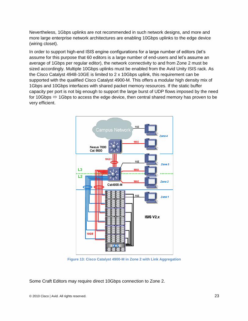
In order to support high-end ISIS engine configurations for a large number of editors (let‘s
assume for this purpose that 60 editors is a large number of end-users and let‘s assume an
average of 1Gbps per regular editor), the network connectivity to and from Zone 2 must be
sized accordingly. Multiple 10Gbps uplinks must be enabled from the Avid Unity ISIS rack. As
the Cisco Catalyst 4948-10GE is limited to 2 x 10Gbps uplink, this requirement can be
supported with the qualified Cisco Catalyst 4900-M. This offers a modular high density mix of
1Gbps and 10Gbps interfaces with shared packet memory resources. If the static buffer
capacity per port is not big enough to support the large burst of UDP flows imposed by the need
for 10Gbps 1Gbps to access the edge device, then central shared memory has proven to be
very efficient.
Figure 13: Cisco Catalyst 4900-M in Zone 2 with Link Aggregation
Some Craft Editors may require direct 10Gbps connection to Zone 2.
© 2010 Cisco | Avid. All rights reserved. 24
Figure 13 shows how the Cisco Catalyst 4900-M can aggregate multiple ISIS engines and
editors at 10Gbps as well as editors connected at 1Gbps. This is because the Cisco Catalyst
4900-M additionally provides the embedded routed Zone 3 at line rate to outside the ISIS media
rack and the demarcation to the enterprise core network (Zone 4).
ISIS 1.x offers a maximum of four physical links per port channel. With ISIS 2.x the maximum number of physical links is extended to up to eight. Notice the port channel configuration on the switch must be set to ―mode on‖ as LACP negotiation is not supported on the ISIS side. The hashing algorithm must be computed based on the layer 3 identifiers (Src & Dst IP addresses).
Zone 2 is not limited to the Cisco Catalyst 49xx series. Other switches such as Cisco Nexus
7000 using Virtual Device Context (VDC) or Cisco Nexus 5000 can be deployed. However, it is important to understand the network resource requirements for 10Gbps and 1Gbps access before doing so. This is discussed in the following sections.
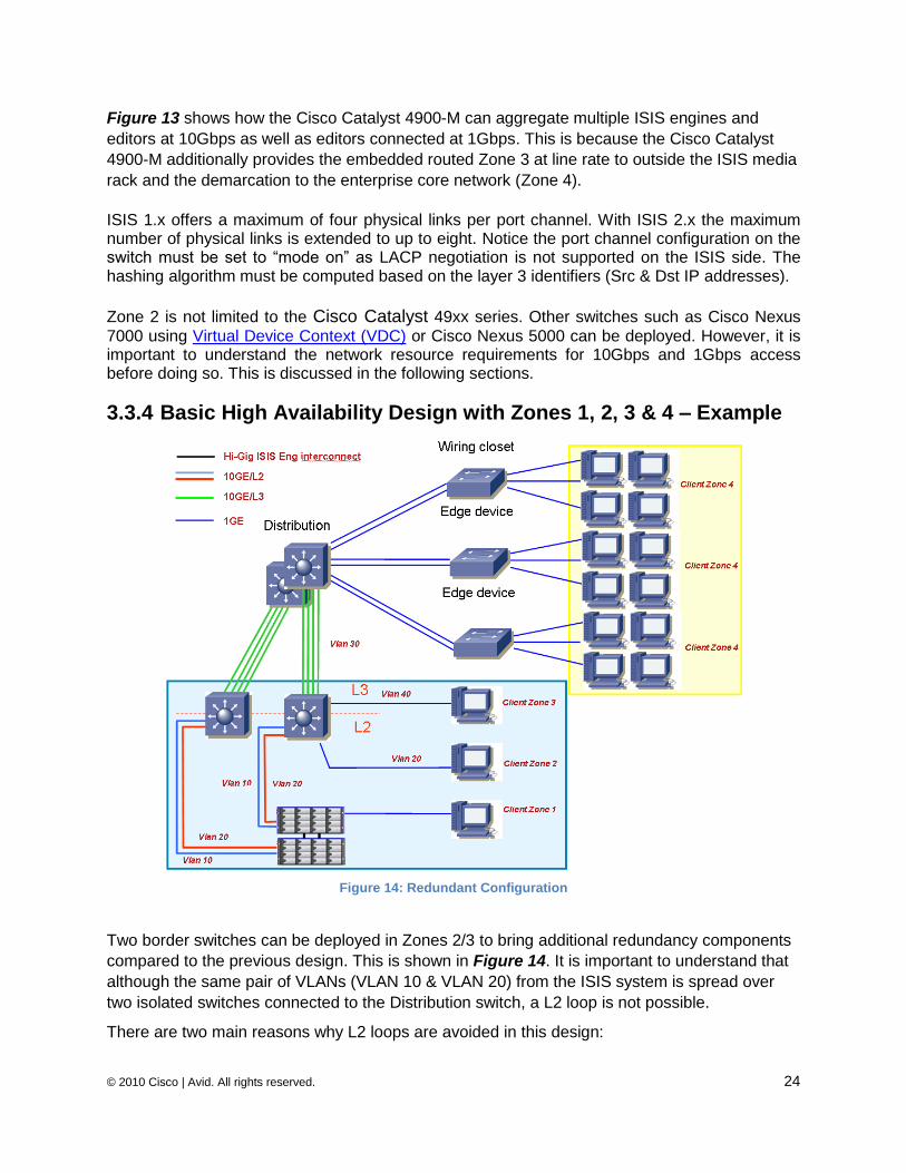
3.3.4 Basic High Availability Design with Zones 1, 2, 3 & 4 – Example
Figure 14: Redundant Configuration
Two border switches can be deployed in Zones 2/3 to bring additional redundancy components
compared to the previous design. This is shown in Figure 14. It is important to understand that
although the same pair of VLANs (VLAN 10 & VLAN 20) from the ISIS system is spread over
two isolated switches connected to the Distribution switch, a L2 loop is not possible.
There are two main reasons why L2 loops are avoided in this design:
© 2010 Cisco | Avid. All rights reserved. 25
There is no inter switch link (L2) between the two standalone switches in Zone 2.
The upward links to the Core switch must be L3 links. Hence HSRP or GLBP must
be enabled to load distribute the L3 traffic between the 2 routed VLAN‘s.
It is important to make sure Layer 3 is enabled between Zone 2 and Zone 4 (Enterprise Layer 3
Infrastructure). Zone 3 (L3) embedded into the switch in Zone 2 addresses the L2 isolation by
interconnecting the different network components using L3 routing. Therefore, redundant paths
and redundant switches are achieved for Zones 2 and 3.
Additional options to improve High Availability in Zone 4 are discussed in the next section.
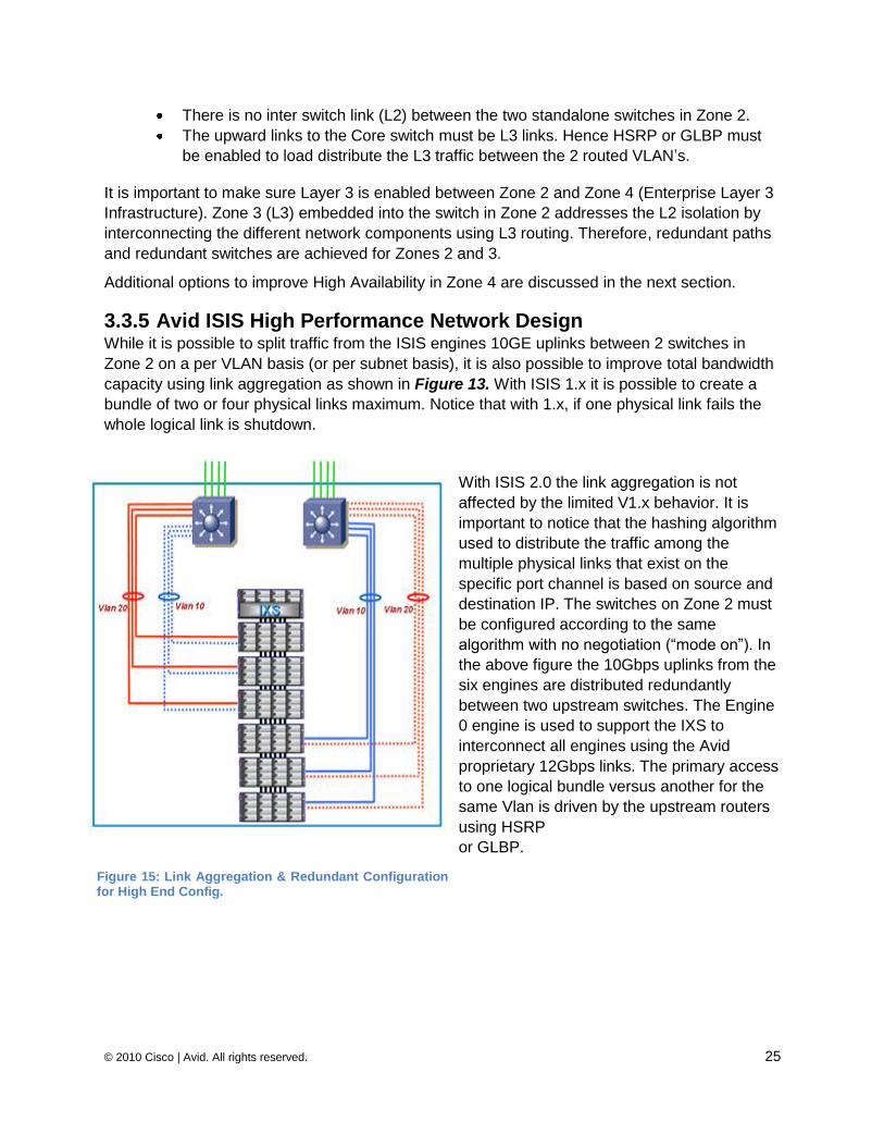
3.3.5 Avid ISIS High Performance Network Design While it is possible to split traffic from the ISIS engines 10GE uplinks between 2 switches in
Zone 2 on a per VLAN basis (or per subnet basis), it is also possible to improve total bandwidth
capacity using link aggregation as shown in Figure 13. With ISIS 1.x it is possible to create a
bundle of two or four physical links maximum. Notice that with 1.x, if one physical link fails the
whole logical link is shutdown.
With ISIS 2.0 the link aggregation is not
affected by the limited V1.x behavior. It is
important to notice that the hashing algorithm
used to distribute the traffic among the
multiple physical links that exist on the
specific port channel is based on source and
destination IP. The switches on Zone 2 must
be configured according to the same
algorithm with no negotiation (―mode on‖). In
the above figure the 10Gbps uplinks from the
six engines are distributed redundantly
between two upstream switches. The Engine
0 engine is used to support the IXS to
interconnect all engines using the Avid
proprietary 12Gbps links. The primary access
to one logical bundle versus another for the
same Vlan is driven by the upstream routers
using HSRP
or GLBP.
Figure 15: Link Aggregation & Redundant Configuration for High End Config.
© 2010 Cisco | Avid. All rights reserved. 26
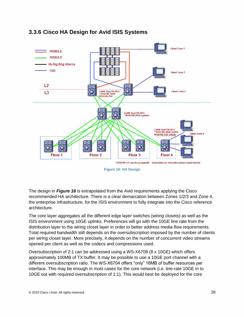
3.3.6 Cisco HA Design for Avid ISIS Systems
Figure 16: HA Design
The design in Figure 16 is extrapolated from the Avid requirements applying the Cisco
recommended HA architecture. There is a clear demarcation between Zones 1/2/3 and Zone 4,
the enterprise infrastructure, for the ISIS environment to fully integrate into the Cisco reference
architecture.
The core layer aggregates all the different edge layer switches (wiring closets) as well as the
ISIS environment using 10GE uplinks. Preferences will go with the 10GE line rate from the
distribution layer to the wiring closet layer in order to better address media flow requirements.
Total required bandwidth still depends on the oversubscription imposed by the number of clients
per wiring closet layer. More precisely, it depends on the number of concurrent video streams
opened per client as well as the codecs and compressions used.
Oversubscription of 2:1 can be addressed using a WS-X6708 (8 x 10GE) which offers
approximately 100MB of TX buffer. It may be possible to use a 10GE port channel with a
different oversubscription ratio. The WS-X6704 offers ―only‖ 16MB of buffer resources per
interface. This may be enough in most cases for the core network (i.e. line-rate 10GE in to
10GE out with required oversubscription of 1:1). This would best be deployed for the core
© 2010 Cisco | Avid. All rights reserved. 27
infrastructure, as the buffer resources are not as large as required on the distribution layer. This
is obviously as long as there is no 1Gbps bottleneck in the core layer.
The Cisco Nexus 7000 with 32 x 10G line cards configured in dedicated mode (to provide 8 x
10GE line rate) can be used as a core switch or as an Aggregation switch connecting the
multiple access switches at 10GE line rate. In this case the buffer resources can be addressed
per editor directly at the wiring closets (Cisco Catalyst series, and Nexus 7000). Nothing else
changes dramatically from any other standard recommended oversubscription ratio but packet
buffer size. Therefore, it is important to provision the correct bandwidth oversubscription
according to the number of clients or video streams due to the large UDP datagrams used by
the ISIS media applications.
In theory, a broadcasting LAN network should be treated like any other regular multi-layer
Campus network. However, some very important considerations apply:
Applications should be tested extensively in real life environments. Not all of them
run properly on a multi-service IP infrastructure.
Testing and interoperability in a real life environment can be challenging when
migrating from legacy media applications and enabling IP with previously ―private‖
broadcaster applications (e.g., audio routers, video mixers, editing desks, satellite
control servers etc.). Deployment can be complicated by negative testing results
which are costly, time consuming, and require ―all hands on deck‖ to fix (broadcaster,
partner, AS, account team, vendor 1, vendor 2, etc.
Dedicated network resources (bandwidth and packet memory) must be allocated and
dimensioned according to the media applications and the number of video streams.
3.4 Media Workflow and Network Services Constraints
3.4.1 Qualified Switches
3.4.1.1 Qualified: Cisco Catalyst 49xx series As of today (March 2010) only one line of Cisco L3 switches, Cisco Catalyst 4948-10GE and
Cisco Catalyst 4900-M, has been qualified to support Gigabit Ethernet connected Avid Video
clients.
Qualification means that Avid has qualified these platforms through its SQA (software
qualification & assurance) process and provides them to its customers as network switch
references to fully support Avid design for Avid Unity ISIS Applications. The SQA process
extensively tests all possible configuration usage and scenarios. The main reason that the Cisco
Catalyst 4948-10GE and Cisco Catalyst 4900-M are ―Qualified‖ by Avid is that the internal
architecture of shared memory provides the capacity to address multiple High Resolution editing
clients (10GE mixed with 1GE) in a 1GE or GEC cascaded fashion.
The Cisco Catalyst 4500 and 4900 series offers the same internal architecture based on a
shared memory fabric. This means that although not qualified by Avid, other Cisco Catalyst
45xx configurations may be supported. This depends on the combination of supervisor and line
cards chosen.
© 2010 Cisco | Avid. All rights reserved. 28
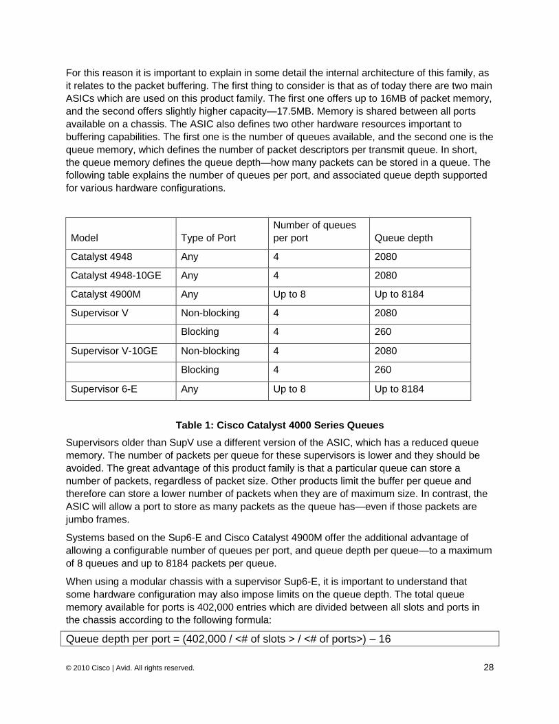
For this reason it is important to explain in some detail the internal architecture of this family, as
it relates to the packet buffering. The first thing to consider is that as of today there are two main
ASICs which are used on this product family. The first one offers up to 16MB of packet memory,
and the second offers slightly higher capacity—17.5MB. Memory is shared between all ports
available on a chassis. The ASIC also defines two other hardware resources important to
buffering capabilities. The first one is the number of queues available, and the second one is the
queue memory, which defines the number of packet descriptors per transmit queue. In short,
the queue memory defines the queue depth—how many packets can be stored in a queue. The
following table explains the number of queues per port, and associated queue depth supported
for various hardware configurations.
Model Type of Port
Number of queues
per port Queue depth
Catalyst 4948 Any 4 2080
Catalyst 4948-10GE Any 4 2080
Catalyst 4900M Any Up to 8 Up to 8184
Supervisor V Non-blocking 4 2080
Blocking 4 260
Supervisor V-10GE Non-blocking 4 2080
Blocking 4 260
Supervisor 6-E Any Up to 8 Up to 8184
Table 1: Cisco Catalyst 4000 Series Queues
Supervisors older than SupV use a different version of the ASIC, which has a reduced queue
memory. The number of packets per queue for these supervisors is lower and they should be
avoided. The great advantage of this product family is that a particular queue can store a
number of packets, regardless of packet size. Other products limit the buffer per queue and
therefore can store a lower number of packets when they are of maximum size. In contrast, the
ASIC will allow a port to store as many packets as the queue has—even if those packets are
jumbo frames.
Systems based on the Sup6-E and Cisco Catalyst 4900M offer the additional advantage of
allowing a configurable number of queues per port, and queue depth per queue—to a maximum
of 8 queues and up to 8184 packets per queue.
When using a modular chassis with a supervisor Sup6-E, it is important to understand that
some hardware configuration may also impose limits on the queue depth. The total queue
memory available for ports is 402,000 entries which are divided between all slots and ports in
the chassis according to the following formula:
Queue depth per port = (402,000 / <# of slots > / <# of ports>) – 16
© 2010 Cisco | Avid. All rights reserved. 29
By default, a port on a 48 port card will have 1192 queue entries per port, and a single queue
per port, based on a 10 slot chassis. Improved default values apply to 6/7 and 3 slot chassis
platforms.
Note: The 4500 SUP II 10G + has also been used successfully for Zone 4 edge switches in some production enviroments, where only the layer 2 functions are deployed and net flow is not required. This SUP has not been qualified by Avid, but can be considered as approved.
3.4.2 Approved Switches
3.4.2.1 Cisco Catalyst 6500 Whereas qualified switches are provided by Avid to support an end-to-end certified solution for
the Avid ISIS perimeter (Zone 1 to Zone 3), customer testing has also been performed on many
other switches. Some of these have been approved for direct connection to ISIS.
Cisco Catalyst 6500 Components:
WS-SUP720-3B Cisco Catalyst 6500
WS-X6748-SFP Cisco Catalyst 6500 48-port Gig Ethernet Mod: fabric-enabled (Req.
SFPs)
WS-X6748-GE-TX& WS-X6724-GE Cisco Catalyst 6500 48-port 10/100/1000 GE
Mod: fabric enabled
WS-X6704-10GE Cisco Catalyst 6500 4-port 10 Gigabit Ethernet Module (req.
XENPAKs)
WS-X6708-10GE Cisco Catalyst 6500 8-port 10 Gigabit Ethernet Module (req. X2)
WS-X67016-10GE Cisco Catalyst 6500 16-port 10 Gigabit Ethernet Module (req. X2)
This Cisco Catalyst 6500 switch is approved only in certain configurations. It is important to
understand when 1GE uplinks are cascaded, the uplinks 1GE line cards of the Cisco Catalyst
6500—even the X67xx series—may not offer enough buffer capacity to support multiple editing
clients shared on the same uplink. However, cascaded 1GE uplinks are best limited to small
network architectures and are not usually recommended by Cisco for most large broadcasters
and enterprise networks.
© 2010 Cisco | Avid. All rights reserved. 30
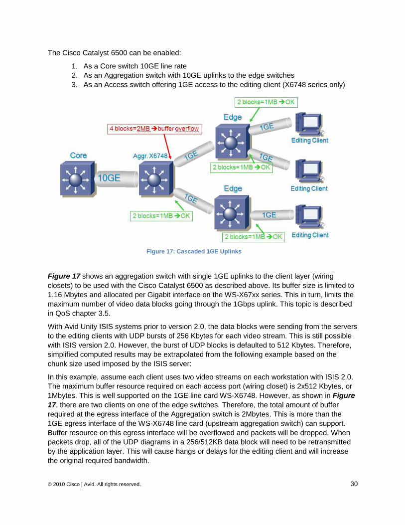
The Cisco Catalyst 6500 can be enabled:
1. As a Core switch 10GE line rate
2. As an Aggregation switch with 10GE uplinks to the edge switches
3. As an Access switch offering 1GE access to the editing client (X6748 series only)
Figure 17 shows an aggregation switch with single 1GE uplinks to the client layer (wiring
closets) to be used with the Cisco Catalyst 6500 as described above. Its buffer size is limited to
1.16 Mbytes and allocated per Gigabit interface on the WS-X67xx series. This in turn, limits the
maximum number of video data blocks going through the 1Gbps uplink. This topic is described
in QoS chapter 3.5.
With Avid Unity ISIS systems prior to version 2.0, the data blocks were sending from the servers
to the editing clients with UDP bursts of 256 Kbytes for each video stream. This is still possible
with ISIS version 2.0. However, the burst of UDP blocks is defaulted to 512 Kbytes. Therefore,
simplified computed results may be extrapolated from the following example based on the
chunk size used imposed by the ISIS server:
In this example, assume each client uses two video streams on each workstation with ISIS 2.0.
The maximum buffer resource required on each access port (wiring closet) is 2x512 Kbytes, or
1Mbytes. This is well supported on the 1GE line card WS-X6748. However, as shown in Figure
17, there are two clients on one of the edge switches. Therefore, the total amount of buffer
required at the egress interface of the Aggregation switch is 2Mbytes. This is more than the
1GE egress interface of the WS-X6748 line card (upstream aggregation switch) can support.
Buffer resource on this egress interface will be overflowed and packets will be dropped. When
packets drop, all of the UDP diagrams in a 256/512KB data block will need to be retransmitted
by the application layer. This will cause hangs or delays for the editing client and will increase
the original required bandwidth.
Figure 17: Cascaded 1GE Uplinks
© 2010 Cisco | Avid. All rights reserved. 31
Until recently, Avid Unity used 256 KBytes chunk size on their System storage. The recent
version 2.0 of the Avid Unity ISIS system offers the choice to create Storage Groups in the ISIS
file system of combined Storage elements. These Storage Groups can now be configured to
either operate using 512 KBytes (default) or 256 KBytes chunk sizes. This option allows for
performance improvement. However, it imposes larger memory capacity on the network
components. Please refer to the Avid ISIS 2.0 Readme file accessible in Section 7.1.3 of this
white paper. At the time this paper was written, the highest version available is 2.0, and any
references to 2.x must be understood as version 2.0.
As long as multiple 1GEs are bundled according to the total memory resources required, or
10GE uplinks are used (preferred to GEC), it is possible to deploy the Cisco Catalyst 6500 or
Nexus 7000 at any layer of the architecture (Core, Aggregation and wiring closets layers).
However, deploying GEC with the Cisco Catalyst 6500 is not as scalable as 10GE interfaces
and must be enabled carefully. It is also very important to note that not all Cisco Catalyst 6500
1GE line cards are appropriate for Media client applications. For example, WS-6148, WS-6348,
WS-6548 cannot be used due to their buffer capacity. WS-X67xx series might be used to
support Low or Medium Resolution editing clients. However, the number of video streams is not
unlimited and must be taken into consideration accordingly before enabling GEC from the
distribution using X6748 line card. 10Gbps uplinks must be the choice for High Resolution and
multiple editing clients to uplink edge layers. As explained before, depending on the
oversubscription required (1:1, 2:1, 4:1) different options can be deployed for the core 10GE
uplinks.
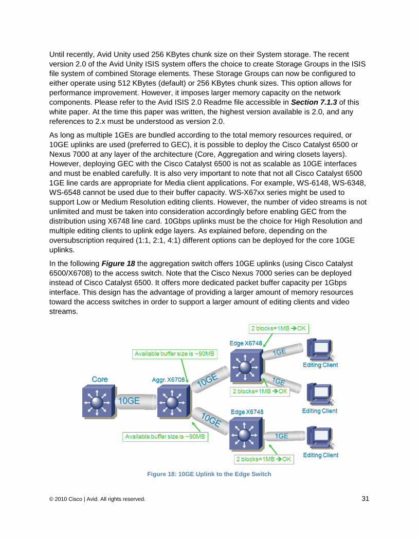
In the following Figure 18 the aggregation switch offers 10GE uplinks (using Cisco Catalyst
6500/X6708) to the access switch. Note that the Cisco Nexus 7000 series can be deployed
instead of Cisco Catalyst 6500. It offers more dedicated packet buffer capacity per 1Gbps
interface. This design has the advantage of providing a larger amount of memory resources
toward the access switches in order to support a larger amount of editing clients and video
streams.
Figure 18: 10GE Uplink to the Edge Switch
© 2010 Cisco | Avid. All rights reserved. 32
.
3.4.3 Additional High-End Cisco Switches At publication, the following switches are not yet qualified or approved by Avid because they are
still under stress lab testing. However, it is obvious that based on the network resource
requirements detailed throughout this document, the Cisco Nexus 7000 series, and in some
particular cases the Cisco Nexus 5000 series, can improve the total throughput or buffer
utilization required to offer a highly scalable and flexible network design to support Avid ISIS
applications.
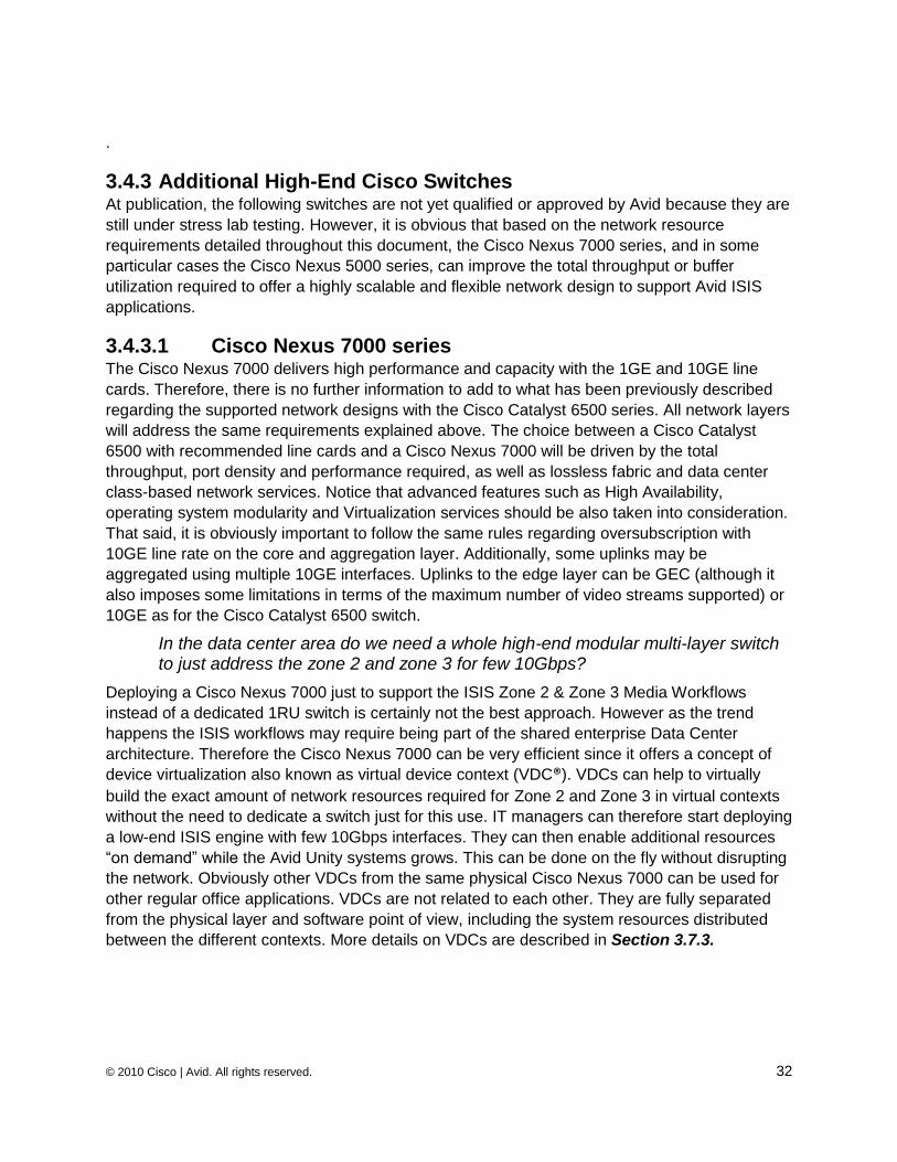
3.4.3.1 Cisco Nexus 7000 series The Cisco Nexus 7000 delivers high performance and capacity with the 1GE and 10GE line
cards. Therefore, there is no further information to add to what has been previously described
regarding the supported network designs with the Cisco Catalyst 6500 series. All network layers
will address the same requirements explained above. The choice between a Cisco Catalyst
6500 with recommended line cards and a Cisco Nexus 7000 will be driven by the total
throughput, port density and performance required, as well as lossless fabric and data center
class-based network services. Notice that advanced features such as High Availability,
operating system modularity and Virtualization services should be also taken into consideration.
That said, it is obviously important to follow the same rules regarding oversubscription with
10GE line rate on the core and aggregation layer. Additionally, some uplinks may be
aggregated using multiple 10GE interfaces. Uplinks to the edge layer can be GEC (although it
also imposes some limitations in terms of the maximum number of video streams supported) or
10GE as for the Cisco Catalyst 6500 switch.
In the data center area do we need a whole high-end modular multi-layer switch to just address the zone 2 and zone 3 for few 10Gbps?
Deploying a Cisco Nexus 7000 just to support the ISIS Zone 2 & Zone 3 Media Workflows
instead of a dedicated 1RU switch is certainly not the best approach. However as the trend
happens the ISIS workflows may require being part of the shared enterprise Data Center
architecture. Therefore the Cisco Nexus 7000 can be very efficient since it offers a concept of
device virtualization also known as virtual device context (VDC®). VDCs can help to virtually
build the exact amount of network resources required for Zone 2 and Zone 3 in virtual contexts
without the need to dedicate a switch just for this use. IT managers can therefore start deploying
a low-end ISIS engine with few 10Gbps interfaces. They can then enable additional resources
―on demand‖ while the Avid Unity systems grows. This can be done on the fly without disrupting
the network. Obviously other VDCs from the same physical Cisco Nexus 7000 can be used for
other regular office applications. VDCs are not related to each other. They are fully separated
from the physical layer and software point of view, including the system resources distributed
between the different contexts. More details on VDCs are described in Section 3.7.3.
© 2010 Cisco | Avid. All rights reserved. 33
Figure 19: Cisco Nexus 7000 with VDC for Zone 2
In addition to the throughput and high buffer capacity available with the Cisco Nexus 7000
series, it is important to take into consideration the following elements that can help to improve
the level of service required to carry the ISIS media workflows with a minimum of disruption.
Virtual Output Queuing and Lossless Fabric
The Cisco Nexus 7000 series offers a lossless fabric with Virtual Output Queues (VoQ‘s) and
central arbitration. The central arbitration mechanism helps to ensure the traffic is delivered at
the egress line cards with no packet loss due to any type of congestion.
One of the main problems with fabric switches is ―head of line blocking‖. As an example,
assuming traffic made of multiple flows coming into the switch via the same ingress line card
has to be delivered to different output interfaces (e.g., GE1, Ten2 and Ten3). If the egress
interface GE1 is congested, then the egress line card will send a flow control to stop the ingress
line card to access the fabric. This will cause all the ports that belong to the same ingress line
card to be affected. For the Media Workflow, if GE1 is the distribution switch uplink connecting
an edge switch with multiple editors attached to it, and if this egress interface becomes
congested, then all the following inbound traffic from the same ingress interface toward non-
congested interfaces will be stopped. Notice that this behavior doesn't apply to non-blocking
© 2010 Cisco | Avid. All rights reserved. 34
shared memory devices. These are—like the Cisco Catalyst 4900 series switches—by definition
not subject to head-of-line blocking.
The Cisco Nexus 7000 implements Virtual Output Queuing (VoQ). Output queues of the egress
modules are virtually represented on the ingress modules, hence providing inbound fabric
capacity on the egress modules. All flows to be transmitted to the fabric are stored on these
VoQs based on their respective destination. In addition, the VoQs are aware of the desired
Class of Service of the packets. When the packet is destined to a congested port, the other
flows coming from the same input line card are transmitted based on the output queue capacity
of their respective target interface and according to the appropriate degree of priority (also
known as class of service). They are therefore not impacted by any other congested egress
interfaces.
Virtual Output Queuing (VoQ) will not be efficient without a per VoQ transaction mechanism.
This important transaction mechanism is the central arbitration which sits on the supervisor.
Central arbitration controls access to the fabric based on available output resources. The central
arbiter monitors available buffers on each egress interface which are represented by the VoQ
on the ingress line cards. Before a packet is sent to the egress interface, it is placed in one of
the VoQs. Then the ingress interface requests grant access to the fabric from the central arbiter.
The central arbiter either provides the requested credit for a particular VoQ or not, depending on
the available transmit buffer capacity at the target egress interface required to send the packet
across the fabric switch.
High Availability
The Cisco Nexus 7000 is a modular switch that offers fully redundant hardware components for
all critical functions as well as a highly available operating system NX-OS.
On the hardware side, any redundant components can be hot swapped without disrupting the
production traffic. Additionally, a distinct functional separation between control plane
(Supervisor) and forwarding data plane (Line Cards) is emphasized in its design in order to
allow continuous operation and zero data loss during planned or unplanned control-plane
events or failures.
On the software side, the Cisco NX-OS™ uses a modular architecture that offers independent
software modules for redundancy, fault isolation, and resource efficiency. These are known as
system service components. Most system services are capable of performing stateful restarts.
This allows a given service experiencing a failure to be restarted and to resume operations
transparent to other services within the platform, and fully transparent to neighboring devices
within the network. Another critical service provided by the NX-OS is the ability to perform in-
service software updates (ISSUs) as well as downgrades without any disruption to the
production traffic. The overall modular software architecture supports plug-in-based services
and features. This function helps to perform complete image upgrades, with little to no impact
on other modules. This capability allows for nonstop forwarding during a software upgrade,
including upgrades between full image versions.
Virtualization
In addition to the well-known layer 2 and Layer 3 service virtualization, the Cisco Nexus 7000
offers two concepts of virtual switching:
© 2010 Cisco | Avid. All rights reserved. 35
A many-to-one virtualization known as vPC (Virtual Port Channel)
This provides layer 2 multipath to take advantage of all available connections. It also
removes reliance on the STP, improving high availability.
A one-to-many virtualization known as VDC (Virtual Device Context)
This consists of creating multiple instances of virtual devices within each physical
device. It offers all available services independently on each context. Hardware
Resources can be partitioned between virtual instances. This offers complete Fault
Isolation and management delineation between each VDC Instance.
Bandwidth Scalability
The Cisco Nexus 7000 architecture supports 230Gbps of bandwidth per slot. As of the writing of
this document (November 2009), 10Gigabit Ethernet I/O modules on the Cisco Nexus 7000 are
capable of supporting 80Gbps of bandwidth per slot. This is an I/O Module limitation and not a
limitation of the available slot bandwidth in the Cisco Nexus 7000 chassis. Future modules
compatible with the Cisco Nexus 7000 chassis will be able to support higher densities of line
rate 10GE ports without requiring a chassis, fabric module or supervisor upgrade.
Bandwidth scalability is important when requirements are driven by very high resolution video
streams. The next generation of editing client workstations may support System Virtualization in
order to take advantages of the full I/O bandwidth. Virtualization is driving editing clients to
adopt 10GE at the access layer by consolidating multiple logical 1 GE interfaces to a single 10
GE interface. As access layers migrate to 10GE this requires higher density of 10GE in the
aggregation and the core layer of the network.
The Cisco Nexus 7000 can support a high-density of 1GE / 10GE ports. It is also ready to
support 40/100GE interfaces in the future, after the relevant IEEE standards are ratified. This
capability of the chassis to scale from 1GE to 100GE provides significant investment protection.
Cisco Nexus 7010 Cisco Nexus 7018
1 Gigabit Ethernet 384 (Dual Supervisor) 768 (Dual Supervisor)
10 Gigabit Ethernet (line-rate) 64 (Dual Supervisor) 128 (Dual Supervisor)
10 Gigabit Ethernet (4:1 Oversubscription)
256 (Dual Supervisor) 512 (Dual Supervisor)
Cisco TrustSec (CTS®) - 802.1AE Link Encryption.
This function enables administrators to encrypt traffic on the wire without the need for any
additional hardware. CTS allows definition and application of an abstract secure group-based
ACL at line rate. This enhances the scalability and portability of ACL. This allows users to define
topology independent ACL policies and Network Authentication for end-points and network
devices.
The above section lists just a few functions that can improve service and security levels.
Additional detail may be found in Reference Section 7.2.1 at the end of this document.
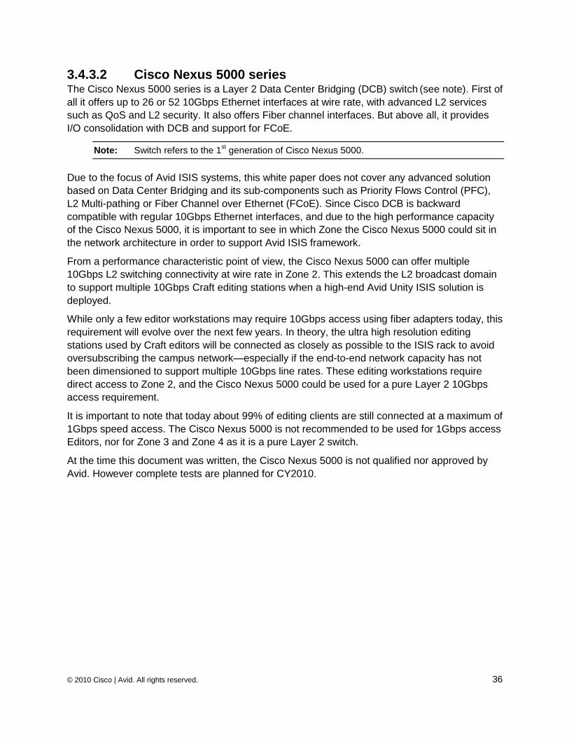
© 2010 Cisco | Avid. All rights reserved. 36
3.4.3.2 Cisco Nexus 5000 series The Cisco Nexus 5000 series is a Layer 2 Data Center Bridging (DCB) switch (see note). First of
all it offers up to 26 or 52 10Gbps Ethernet interfaces at wire rate, with advanced L2 services
such as QoS and L2 security. It also offers Fiber channel interfaces. But above all, it provides
I/O consolidation with DCB and support for FCoE.
Note: Switch refers to the 1st generation of Cisco Nexus 5000.
Due to the focus of Avid ISIS systems, this white paper does not cover any advanced solution
based on Data Center Bridging and its sub-components such as Priority Flows Control (PFC),
L2 Multi-pathing or Fiber Channel over Ethernet (FCoE). Since Cisco DCB is backward
compatible with regular 10Gbps Ethernet interfaces, and due to the high performance capacity
of the Cisco Nexus 5000, it is important to see in which Zone the Cisco Nexus 5000 could sit in
the network architecture in order to support Avid ISIS framework.
From a performance characteristic point of view, the Cisco Nexus 5000 can offer multiple
10Gbps L2 switching connectivity at wire rate in Zone 2. This extends the L2 broadcast domain
to support multiple 10Gbps Craft editing stations when a high-end Avid Unity ISIS solution is
deployed.
While only a few editor workstations may require 10Gbps access using fiber adapters today, this
requirement will evolve over the next few years. In theory, the ultra high resolution editing
stations used by Craft editors will be connected as closely as possible to the ISIS rack to avoid
oversubscribing the campus network—especially if the end-to-end network capacity has not
been dimensioned to support multiple 10Gbps line rates. These editing workstations require
direct access to Zone 2, and the Cisco Nexus 5000 could be used for a pure Layer 2 10Gbps
access requirement.
It is important to note that today about 99% of editing clients are still connected at a maximum of
1Gbps speed access. The Cisco Nexus 5000 is not recommended to be used for 1Gbps access
Editors, nor for Zone 3 and Zone 4 as it is a pure Layer 2 switch.
At the time this document was written, the Cisco Nexus 5000 is not qualified nor approved by
Avid. However complete tests are planned for CY2010.
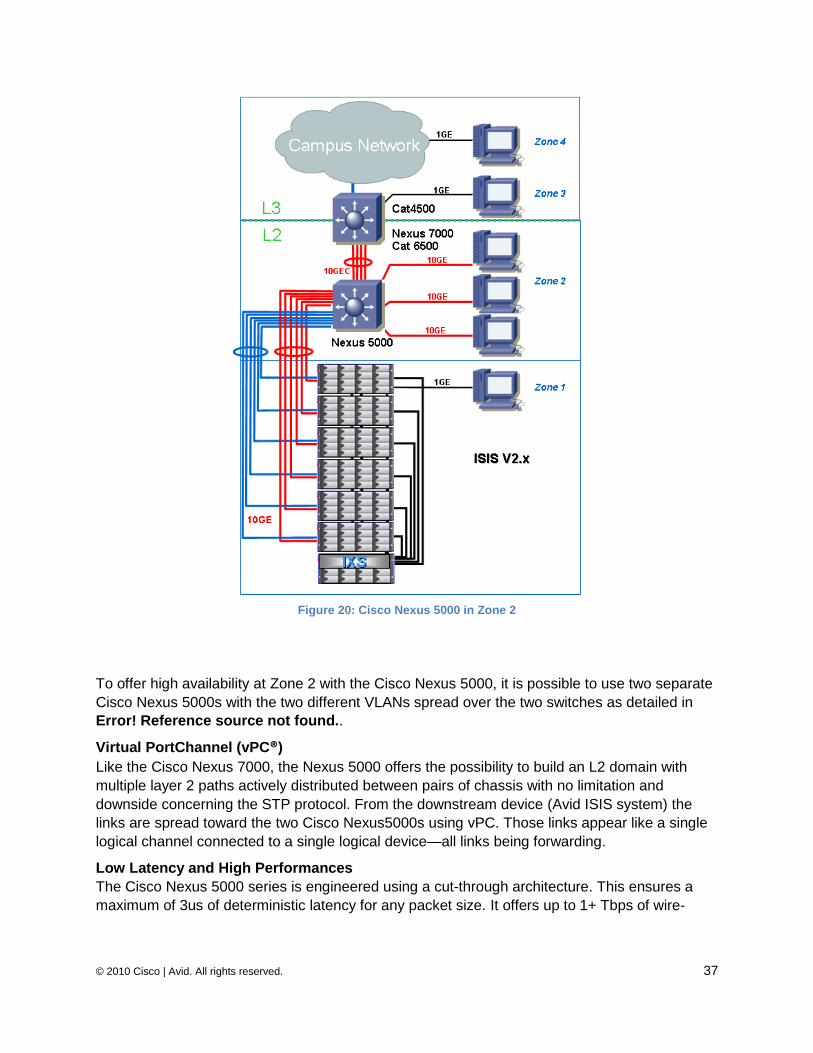
© 2010 Cisco | Avid. All rights reserved. 37
Figure 20: Cisco Nexus 5000 in Zone 2
To offer high availability at Zone 2 with the Cisco Nexus 5000, it is possible to use two separate
Cisco Nexus 5000s with the two different VLANs spread over the two switches as detailed in
Error! Reference source not found..
Virtual PortChannel (vPC®)
Like the Cisco Nexus 7000, the Nexus 5000 offers the possibility to build an L2 domain with
multiple layer 2 paths actively distributed between pairs of chassis with no limitation and
downside concerning the STP protocol. From the downstream device (Avid ISIS system) the
links are spread toward the two Cisco Nexus5000s using vPC. Those links appear like a single
logical channel connected to a single logical device—all links being forwarding.
Low Latency and High Performances
The Cisco Nexus 5000 series is engineered using a cut-through architecture. This ensures a
maximum of 3us of deterministic latency for any packet size. It offers up to 1+ Tbps of wire-
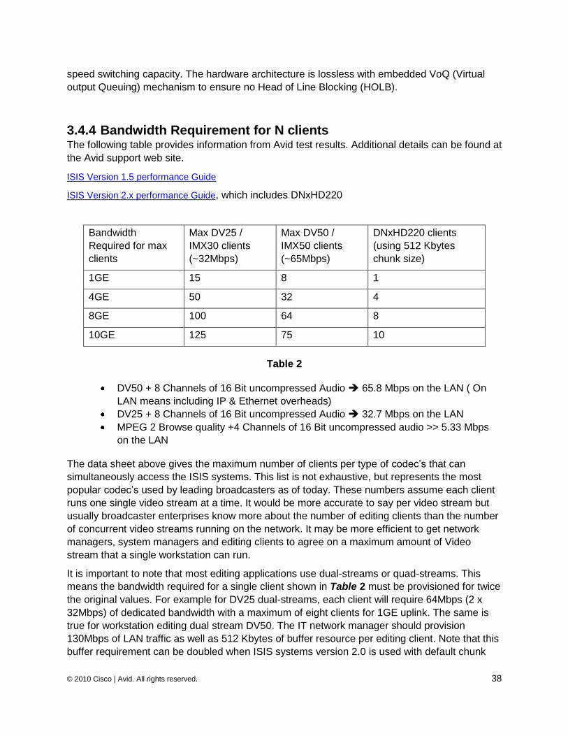
© 2010 Cisco | Avid. All rights reserved. 38
speed switching capacity. The hardware architecture is lossless with embedded VoQ (Virtual
output Queuing) mechanism to ensure no Head of Line Blocking (HOLB).
3.4.4 Bandwidth Requirement for N clients The following table provides information from Avid test results. Additional details can be found at
the Avid support web site.
ISIS Version 1.5 performance Guide
ISIS Version 2.x performance Guide, which includes DNxHD220
Bandwidth
Required for max
clients
Max DV25 /
IMX30 clients
(~32Mbps)
Max DV50 /
IMX50 clients
(~65Mbps)
DNxHD220 clients
(using 512 Kbytes
chunk size)
1GE 15 8 1
4GE 50 32 4
8GE 100 64 8
10GE 125 75 10
Table 2
DV50 + 8 Channels of 16 Bit uncompressed Audio 65.8 Mbps on the LAN ( On
LAN means including IP & Ethernet overheads)
DV25 + 8 Channels of 16 Bit uncompressed Audio 32.7 Mbps on the LAN
MPEG 2 Browse quality +4 Channels of 16 Bit uncompressed audio >> 5.33 Mbps
on the LAN
The data sheet above gives the maximum number of clients per type of codec‘s that can
simultaneously access the ISIS systems. This list is not exhaustive, but represents the most
popular codec‘s used by leading broadcasters as of today. These numbers assume each client
runs one single video stream at a time. It would be more accurate to say per video stream but
usually broadcaster enterprises know more about the number of editing clients than the number
of concurrent video streams running on the network. It may be more efficient to get network
managers, system managers and editing clients to agree on a maximum amount of Video
stream that a single workstation can run.
It is important to note that most editing applications use dual-streams or quad-streams. This
means the bandwidth required for a single client shown in Table 2 must be provisioned for twice
the original values. For example for DV25 dual-streams, each client will require 64Mbps (2 x
32Mbps) of dedicated bandwidth with a maximum of eight clients for 1GE uplink. The same is
true for workstation editing dual stream DV50. The IT network manager should provision
130Mbps of LAN traffic as well as 512 Kbytes of buffer resource per editing client. Note that this
buffer requirement can be doubled when ISIS systems version 2.0 is used with default chunk
© 2010 Cisco | Avid. All rights reserved. 39
sizes. It is even possible to see high definition video editing clients running four video streams
(or equivalent when running Picture in Picture) that will result in requirements four times the
original bandwidth for a DV50 video frame. This would require about 260Mbps of bandwidth and
1MB of buffer memory available just for one single client.
In Figure 17 the buffer pool allocation explains why a 1GE interface with the Cisco Catalyst
6500 may not be sufficient for two clients—each running dual-streams of high resolution video
editing (the X6748 supports a maximum of 1.1MB of TX buffer per egress interface). Buffer
resources are explained in Chapter 3.4.5
Network manager requirements are increased when the existing network infrastructure is built
with an oversubscription ratio not dimensioned to support multiple high resolution editing clients.
It is possible to see why IT managers starts off by forcing broadcaster clients in Zone 4 (the
campus network) to only access low resolution editing, while clients in Zones 2 or 3 are
preferred for high resolution use.
Another option is to limit the number of high resolution editing clients per edge switch on Zone 4
according to the max bandwidth and buffer available. However, this does not help broadcasters
with future growth planned or who have new high resolution codecs!
Until now, editing applications did not allow clients to limit the number of concurrent video
streams to be used for editing. This had to be done using the internal ISIS GUI or the ISIS client
in 2.x in order to control and limit the bandwidth itself. It is recommended that the editing client
and network manager agree on the max number of concurrent video streams that can be edited.
It is important to design the architecture according to the number of video streams opened per
client as well as according to compression and codecs used. Network managers must apply the
Cisco recommended design to provide the appropriate bandwidth and HA requirements and
avoid multi-cascaded switches using 1GE uplinks.
In the meantime, due to new high resolution codec, the core must be a 10GE-based non-
blocking and even in some cases, multi-10GE-based Port-channels.
If there are multiple concurrent streams served to one or multiple clients connected to the same
edge switch, then the total rate of 2:1 burst will increase according to the number of video
streams. The shared egress interface on the uplink switch must then be able to offer all of the
memory resource required for multiple video streams. This solution cannot work for an extended
period of time, and the final client will be rapidly impacted by packet lost if the upstream switch
cannot address the required resources.
3.4.5 Buffering Usually an editing client uses an oversubscription model, which means that sufficient buffering
capacity must exist for each client—not only at the edge switch on each dedicated egress port—
but also in the aggregation layer to support the total number of editing clients behind each uplink
to the access layer. From end-to-end, all uplinks should be dimensioned to address the buffer
resources according to all the existing clients spread over the different edge components. The
same accountancy model as for bandwidth should be applied on the client itself. Understanding
the number of streams or picture-in-picture a particular client will run on its workstation is as
© 2010 Cisco | Avid. All rights reserved. 40
important as the total number of clients. This will dictate the buffer capacity required for each
editing workstation in addition to the shared bandwidth usage.
If most of the core and distribution layers are built with 10GE interconnections, the aggregation
switch must be able to offer high memory capacity to support all of the high bursts from the
editing applications. This means that oversubscription from 10GE (Ingress) to 1GE or 1GE port-
channel uplinks (Egress) must be taken into consideration in determining the shared buffer
capacity per uplink as detailed in Figure 17 and Figure 18.
Avid ISIS systems use an aggressive protocol to handle video data blocks between clients and
the servers. Although this protocol consumes a large amount of resources, it can work well on
the top of a network architecture built with high-end performance switches. Multilayer switches,
uplink capacity and high availability must be designed to fully optimize all hardware resources,
and uplinks must be distributed intelligently. Gigabit Ethernet switches need to be able to
manage media flow with oversubscription, (i.e. ability of the 1G port to buffer multiple 256Kbytes
bursts of media traffic sent from the 10G+ interfaces). All of this imposes rigorous requirements
on network platforms and oversubscription design.
The most important traffic of media flow travels from the ISIS Application Servers (ISB) to the
editing clients. If the traffic from multiple GE or 10GE interfaces is aggregated onto a single GE
uplink shared by multiple editing clients, then congestion is likely to happen, and packet drop
will occur. This is referred to as the aggregation problem and can be addressed with two
approaches:
1. Use a switch (like the Cisco Catalyst 4000 series (C45xx, C49xx)) that provides
dynamic shared memory from which all interfaces can use resources.
2. Design uplinks between the aggregation and access switches using 10GE uplinks or
multiple 1GE port-channels based on the resources available on each physical
interface according to the number of editing clients (and of course the number of
streams opened and the codecs in use by each client). While this issue is likely to be
transparent for a limited number of clients sharing the same resources, if a large
concentration of multiple traffic streams should occur from the same uplink, this
scenario can cause congestion on an egress interface on the upstream switch. This
polarization on the same physical link may disrupt all editing stations that share this
uplink. This is also referred to as the confluence problem. Also this option implies
that enough 1GE or 10GE interfaces are already provisioned, especially when the
deployment for an ISIS system is done on top of a ―regular‖ Enterprise network
infrastructure.
3.4.5.1 Application Oversubscription It is important to understand that a client running multiple streams may use multiple servers in
parallel. Each stream is served by a different ISIS storage server. The main reason is that the
ISIS application protocol works by over-subscribing the client bandwidth. For example, there
may be two physical servers (ISBs) connected. Each is connected at 1GE and is sending data
at multi gigabits per second to a single client running quad-streams on the same screen. The
ISIS editing application itself is connected at a gigabit. This is called network oversubscription.
Obviously, this solution may not work for an extended period of time, and somehow the network
© 2010 Cisco | Avid. All rights reserved. 41
should rate limit at the ingress side to avoid oversubscription to the client. Editing actions bring
several requests to the servers (e.g. to play, forward, cut & paste, rewind, etc.) This is defined
as ―ultra real-time‖ video editing on the original media content located on the ISIS systems.
One option to handle longer periods of over-subscription is to deploy deeper buffers. However,
this comes at the cost of higher latency (delay) and jitter (variation in delay) in the network. A
delay is introduced because data has to wait in the queue before being transmitted to wire. Jitter
comes from the fact that data will sometimes hit an empty buffer and be transmitted right away
and at other times it will hit a half-full buffer and will have to wait. This is detailed in Section
QoS 3.5.1.
Many applications, especially those based on TCP, will react to data loss by reducing the data
transmission rate at the server end, adapting the traffic to the network transmission
characteristics at that point in time.
The Avid ISIS application uses UDP instead of TCP and doesn't adapt well to packet drops.
However in a ―lossless‖ network architecture design, applications with large bursts of UDP
datagram should work faster. This is why the UDP protocol has historically been used in a LAN
environment.
3.4.5.2 Data Transmission The basic operation of the Avid application is that the client sends requests to multiple physical
servers (ISBs) at the same time. The corresponding ISBs reply by sending data (a part of a
video stream) to the client.
The request from the editing client is usually small (a single Ethernet frame), while the reply
from the ISIS server is quite large: 256 Kbytes or 512 Kbytes with ISIS 2.x of data divided in 5
IP UDP datagram's (approx 52 Kbytes each). Because the MTU size on an IP network (without
Jumbo Frames) is 1500 Bytes, each datagram gets broken down by the IP stack of the ISIS
server (ISB) into approximately 35 fragments. These are sent to the receiving client. The client
must then re-assemble the full datagram and send the IP stack up to the application.
If just one 1500 Byte IP fragment is lost, the client will wait a certain time for the packet to arrive
before it determines that the packet has been lost and asks for a retransmission. Since the 1500
Byte frame was a fragment of a block of 52 Kbytes from 35 fragments, the whole UDP datagram
of 256 Kbytes or 512 Kbytes is retransmitted. This behavior of retransmission obviously has a
visual impact on the editing client. It is difficult to reproduce the same behavior with traffic
generator, hence this is one of the main reasons why testing and certification must also be
consolidated in a ―real‖ production environment to be as accurate as possible.
In practice, packet loss causes the application performance of a single client to rapidly drop off
from approximately 70 Mbps (1 Video Channel – DV50 + 8 Audio Channels) to a few Mbps.
Because of the UDP fragmentation, the application client will ask for a retransmission of all UDP
datagrams.
When the client is set for Medium resolution it may receive data from 2 Gigabit Ethernet
connected disks concurrently.
© 2010 Cisco | Avid. All rights reserved. 42
3.4.6 Switch Buffering Architectures and Limitations As previously described, the Cisco Catalyst 4948-10GE offers a dynamic buffering scheme
shared between all interfaces. This means than at any time, any interface can use the buffer
resource from a shared memory pool. This is helpful to enable multiple 1GE port-channel
uplinks to avoid the upstream uplink becoming a single point of congestion. The Cisco Catalyst
49xx or 45xx-E series will be used when 1GE or GEC will be enabled as shared uplinks to
cascaded edge switches.
Contrary to the Cisco Catalyst 4000 series, the Cisco Catalyst 6500 offers more memory
resources on the line card. However, it is assigned with a specific amount of memory per
interface that cannot be shared between interfaces. Unused buffer resources on one physical
interface cannot be allocated to a port which needs more than its normal assignment. This
restricts the design options for this platform in terms of the number of streams that can be
supported on an individual 6500 series using a single Gigabit Ethernet uplink to serve multiple
editing clients.
Therefore, the 10GE interfaces supporting larger Transmit Port Buffer capacity must be
deployed to connect the edge devices supporting around 20 clients (5MB buffer required) or
forty clients (10MB buffer required). This is assuming each client runs a single video stream with
ISIS v1.x. The maximum number of editors per 10Gbps uplink should be divided by two if the
ISIS application is configured to use bursts of 512Kbytes (ISIS 2.0).
Note: For any ISIS deployments using 1GE cascaded architecture, the designs must be
approved by Avid.
3.5 Quality of Service
3.5.1 Latency and Jitter
The following table is from Avid test results and is provided only for information purposes.
Latency Applied Result Usable
0ms System performs on test network as if locally attached Yes
5ms Noticeable degradation in scrubbing performance, slight delay
in play function (minimal)
Yes
10ms Particularly noticeable delay in scrubbing, 1s delay from
pressing play to material playing, may not be suitable for
editors
Limited
20ms More noticeable delay in scrubbing, 2.5s delay from pressing
play to material playing – this would most likely be unsuitable
for editors
No
50ms Unusable delay from pressing play, buffer ran out after 4-5
seconds
No
Figure 21: Latency and Jitter Based on a Large PING via PATHDIAG (3.2.2.3)
© 2010 Cisco | Avid. All rights reserved. 43
The real-time nature of editing high bandwidth video in a collaborative environment means that
tolerance for delay and jitter is small.
ISIS client applications, like any broadcaster video applications, are latency sensitive as detailed
in Section 3.5.2 QoS below. An editing application needs to be very responsive. Most video
editing applications have been designed for high speed LAN environments. When latency
reaches 5ms, it becomes noticeable. At 10ms it becomes difficult to work with, and at 20ms it is
unworkable. Above 10-15ms of latency, the network is no longer transparent for editing clients
(big visual impact) and most clients would consider it impossible to use their application with
such response times.
This means that no « slow » devices are to be inserted between the servers and the editing
client (such as data inspection devices or firewalls).
This section provides an overview of the Quality of Service (QoS) tools and design that include
high-level answers to the following questions:
What is Quality of Service?
Why is Quality of Service Important for Media Networks?
What is Cisco‘s Quality of Service Toolset?
How to Optimally Deploy QoS for Media Networks?
3.5.2 QoS: Definition At a high level, QoS is the measure of a network‘s transmission quality and service availability.
The service availability part of QoS is a crucial foundational element. The network infrastructure
must be designed to be highly available before you can successfully implement QoS.
The section below focuses on transmission quality, and we will refer to QoS as the term to
define it.
The key factors determining end-to-end network transmission quality are ―packet loss‖, ―end-
to-end latency‖ and induced ―jitter‖.
Packet Loss
A relative measure of the number of packets that were not received compared to the total
number of packets transmitted.
Several events may induce packet loss in a network:
Convergence on the link, or a node failure that should be covered by a HA design
and re-routing optimizations
Excessive link congestion which is the main condition covered by diverse QoS
models described below
Congestion may be avoided by over-provisioning bandwidth versus flow requirement
Node resource exhaustion, such as buffers or processing, is often due to high traffic
bursts
In the case of temporary congestion, such as bursts of traffic, packets are queued. When the
queue is full, excess packets are dropped
© 2010 Cisco | Avid. All rights reserved. 44
End to end latency (delay)
The finite amount of time it takes a packet to reach the receiving endpoint after being
transmitted from the sending endpoint.
Delay in a network is mainly due to five elements:
Physical transmission over optical nodes and fiber induced latency. Therefore, the
optical path is always a key element to consider. An average of 2ms per 100km is a
standard estimation. This value has to be highlighted with media applications which
may be disrupted with latency over 5 to 10ms (detailed in section 3.5.1.
Switching node latency due to processing time is in the order of µs when using
switches, whenever they are handling L2 or L3 frames. Depending on switching
processing (cut-through or store-and-forward modes), this value may vary between 2
and 20µs, which is negligible for these types of applications.
Network service nodes induce a higher latency, around 5ms, due to the deep
inspection of stateful flows. Well-known network service devices are Firewalls, deep
packet inspection and load balancers.
Queuing for resource allocation is an important contributor to latency, and very
sensitive flows should consider a congestion-free design.
Serialization delay is a large contributor to latency when you have a large stream to
send over a physical media. Serialization delay is equal to stream size divided by
bandwidth.
In a congestion-free state, egress speed is faster than ingress arrival. Therefore, queue is
statistically empty, and average waiting time in queue is null.
In a high congestion state, egress queue is filling up to the overflow. Therefore, latency is equal
to queue size divided by link speed.
Applications with large bursts (like Avid file transfer) will face latency at speed adaption point.
Delay variation (Jitter)
This is the difference in the end-to-end delay between packets. For example, if one packet
requires 2ms to traverse the network from the source endpoint to the destination endpoint, and
the subsequent packet requires 5ms to make the same trip, then the delay variation is 3ms.
It is usually recommended that jitter-sensitive flows implement edge buffering to alleviate
dependency.
Jitter is a constant occurrence in a network due to queuing for access to resources. Jitter is
induced mainly by two mechanisms:
Congestion variation over the time due to traffic burst or concurrent streams
Mutual influence of output queues, when multiple types of traffic are mixed on
same link
© 2010 Cisco | Avid. All rights reserved. 45
3.5.3 The Important Aspect of QoS for the Media Workflow The amount and resolution of real-time media traffic is typically of a higher order of magnitude
than found in regular business networks. Therefore, the impact of uncontrolled QoS elements is
very important.
A real-time traffic flow sends packet information in synchronization at encoding speed, while
ultra real-time traffic sends encoded information faster than real-time, with synchronization
readjusted by application. Typically in the media broadcaster environment, real-time flows use
RTP in a timed-based rhythm, while ultra real-time flows are simulated by the action of the
broadcaster client (a.k.a. Jog, forward, fast-forward, rewind, fast-rewind, pause, start,
accelerate, etc.). Real-time flows are mainly used for distributing media, while post-production
mainly uses an ultra real-time mechanism to exchange video frames between the storage
system and the editing clients. Avid file-transfer uses an ultra real-time approach that sends the
encoded content at a very high speed, but still requires it to be resynchronized with display.
Most business applications use TCP as a congestion handling mechanism. This allows smooth
adaptation of flows to network real capacity. TCP relies on a dynamic windowing stream through
packet loss detection to adjust volume of flows to network capacity.
Avid‘s application has been built around Local Area Network. Therefore, packet loss is not an
option in an Avid Media workflow. TCP is not perceived as the correct transmission layer
protocol. UDP is the selected Avid alternative.
As UDP does not offer any reliability a file transfer application mechanism has been
implemented to deliver the average bandwidth required by user, assuming the network can
handle it.
To allow the application to survive in the case of very rare packet loss, an
acknowledge/retransmit mechanism is implemented in the application layer.
In this respect, media flows are very different from business flows that are essentially adaptive.
Media flows are qualified as ‗Inelastic flows‘; while TCP-based flows are ‗Elastic flows‘.
The key quality for an Avid Media network is then ―Loss-less transport service for packet loss
sensitive applications‖.
In depth analysis of media flow burst implication to QoS:
UDP-based ultra real-time file transfer with Avid Unity ISIS used 256 Kbyte bursts
prior to ISIS version 2.0. Avid Unity ISIS now uses 512Kbyte bursts by default.
With this approach, no adaptive mechanism is required, but network design must be able to
losslessly deliver these 65Mbps (i.e. with DV50). This means a huge train in a row of 171 IP
(256Kbytes/1500) packets of 1500Bytes or 342 IP packets when using 512 Kbytes of burst.
It has to be noted that high resolution flows may require 270Mbps. In addition, Avid ISIS v2
increases UDP streams to 512 Kbytes. This increases the pressure on link buffer drop and
latency.
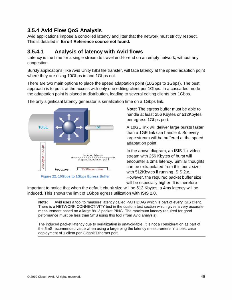
© 2010 Cisco | Avid. All rights reserved. 46
3.5.4 Avid Flow QoS Analysis Avid applications impose a controlled latency and jitter that the network must strictly respect.
This is detailed in Error! Reference source not found.
3.5.4.1 Analysis of latency with Avid flows Latency is the time for a single stream to travel end-to-end on an empty network, without any
congestion.
Bursty applications, like Avid Unity ISIS file transfer, will face latency at the speed adaption point
where they are using 10Gbps in and 1Gbps out.
There are two main options to place the speed adaptation point (10Gbps to 1Gbps). The best
approach is to put it at the access with only one editing client per 1Gbps. In a cascaded mode
the adaptation point is placed at distribution, leading to several editing clients per 1Gbps.
The only significant latency generator is serialization time on a 1Gbps link.
Note: The egress buffer must be able to
handle at least 256 Kbytes or 512Kbytes
per egress 1Gbps port.
A 10GE link will deliver large bursts faster
than a 1GE link can handle it. So every
large stream will be buffered at the speed
adaptation point.
In the above diagram, an ISIS 1.x video
stream with 256 Kbytes of burst will
encounter a 2ms latency. Similar thoughts
can be extrapolated from this burst size
with 512Kbytes if running ISIS 2.x.
However, the required packet buffer size
will be especially higher. It is therefore
important to notice that when the default chunk size will be 512 Kbytes, a 4ms latency will be
induced. This shows the limit of 1Gbps egress utilization with ISIS 2.0.
Note: Avid uses a tool to measure latency called PATHDIAG which is part of every ISIS client. There is a NETWORK CONNECTIVITY test in the custom test section which gives a very accurate measurement based on a large 8912 packet PING. The maximum latency required for good peformance must be less than 5mS using this tool (from Avid analysis).
The induced packet latency due to serialization is unavoidable. It is not a consideration as part of the 5mS recommnded value when using a large ping the latency measuremens in a best case deployment of 1 client per Gigabit Ethernet port.
Figure 22: 10Gbps to 1Gbps Egress Buffer
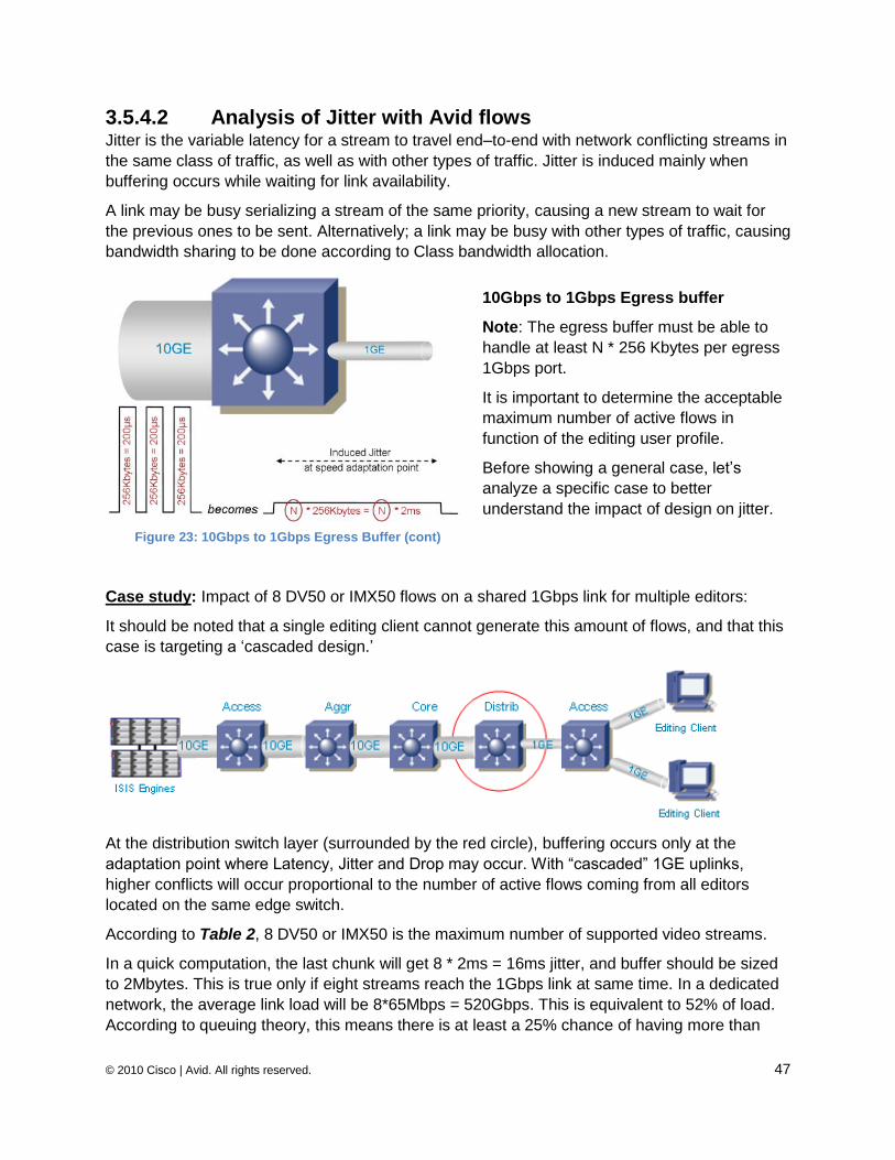
© 2010 Cisco | Avid. All rights reserved. 47
3.5.4.2 Analysis of Jitter with Avid flows Jitter is the variable latency for a stream to travel end–to-end with network conflicting streams in
the same class of traffic, as well as with other types of traffic. Jitter is induced mainly when
buffering occurs while waiting for link availability.
A link may be busy serializing a stream of the same priority, causing a new stream to wait for
the previous ones to be sent. Alternatively; a link may be busy with other types of traffic, causing
bandwidth sharing to be done according to Class bandwidth allocation.
10Gbps to 1Gbps Egress buffer
Note: The egress buffer must be able to
handle at least N * 256 Kbytes per egress
1Gbps port.
It is important to determine the acceptable
maximum number of active flows in
function of the editing user profile.
Before showing a general case, let‘s
analyze a specific case to better
understand the impact of design on jitter.
Case study: Impact of 8 DV50 or IMX50 flows on a shared 1Gbps link for multiple editors:
It should be noted that a single editing client cannot generate this amount of flows, and that this
case is targeting a ‗cascaded design.‘
At the distribution switch layer (surrounded by the red circle), buffering occurs only at the
adaptation point where Latency, Jitter and Drop may occur. With ―cascaded‖ 1GE uplinks,
higher conflicts will occur proportional to the number of active flows coming from all editors
located on the same edge switch.
According to Table 2, 8 DV50 or IMX50 is the maximum number of supported video streams.
In a quick computation, the last chunk will get 8 * 2ms = 16ms jitter, and buffer should be sized
to 2Mbytes. This is true only if eight streams reach the 1Gbps link at same time. In a dedicated
network, the average link load will be 8*65Mbps = 520Gbps. This is equivalent to 52% of load.
According to queuing theory, this means there is at least a 25% chance of having more than
Figure 23: 10Gbps to 1Gbps Egress Buffer (cont)
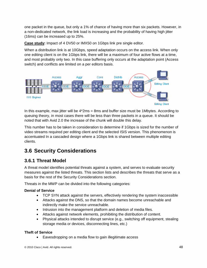
© 2010 Cisco | Avid. All rights reserved. 48
one packet in the queue, but only a 1% of chance of having more than six packets. However, in
a non-dedicated network, the link load is increasing and the probability of having high jitter
(16ms) can be increased up to 25%.
Case study: Impact of 4 DV50 or IMX50 on 1Gbps link pre single editor.
When a distribution link is at 10Gbps, speed adaptation occurs on the access link. When only
one editing client is on the 1Gbps link, there will be a maximum of four active flows at a time,
and most probably only two. In this case buffering only occurs at the adaptation point (Access
switch) and conflicts are limited on a per editors basis.
In this example, max jitter will be 4*2ms = 8ms and buffer size must be 1Mbytes. According to
queuing theory, in most cases there will be less than three packets in a queue. It should be
noted that with Avid 2.0 the increase of the chunk will double this delay.
This number has to be taken in consideration to determine if 1Gbps is sized for the number of
video streams required per editing client and the selected ISIS version. This phenomenon is
accentuated In a cascaded design where a 1Gbps link is shared between multiple editing
clients.
3.6 Security Considerations
3.6.1 Threat Model
A threat model identifies potential threats against a system, and serves to evaluate security
measures against the listed threats. This section lists and describes the threats that serve as a
basis for the rest of the Security Considerations section.
Threats in the MWP can be divided into the following categories:
Denial of Service
TCP SYN attack against the servers, effectively rendering the system inaccessible
Attacks against the DNS, so that the domain names become unreachable and
indirectly make the service unreachable.
Intrusion into the management platform and deletion of media files.
Attacks against network elements, prohibiting the distribution of content.
Physical attacks intended to disrupt service (e.g., switching off equipment, stealing
storage media or devices, disconnecting lines, etc.)
Theft of Service
Eavesdropping on a media flow to gain illegitimate access
© 2010 Cisco | Avid. All rights reserved. 49
Intrusion into the management platform and illegitimately copying a media file.
Faking user credentials to get access to streams
Breaking system limits to get access to more streams than permissible.
Physical attacks, such as stealing a hard disk with a new movie, with the aim to get
illegitimate access to the media.
Integrity Attacks
Breaking into the management system and modifying content, channel
assignments, etc.
Physical attacks, such as replacing authentic hard disks with disks with
wrong content.
Attacks can be carried out from outside the trusted zone (e.g., any PC in the corporate network),
or from the inside the trusted zone (for example, a network administrator misconfiguring the
network, either deliberately or inadvertently).
Physical attacks are extremely powerful and allow any form of attack. They need to be
addressed by physical security measures, such as access control to equipment rooms. Since
this type of threat is not network related, it is not discussed further in this document.
Note that there are several ways to execute a threat; for example, a denial of service attack can
be executed by breaking into a system and corrupting or deleting media files, or by attacking
core switching platforms. The threat model discussed here focuses on the abstract threat,
independent of the method used to execute it.
3.6.2 Security Zone Concepts While security should be an integral part of every component in a system, it is common practice
to divide an architecture into security zones, and to assume that security measures apply
primarily on inter-zone boundaries.
A zone is comprised by devices that share similar security attributes. The key attributes are the
value of the devices and the data stored on them, vulnerability level and exposure to threats,
and probability of exploit or abuse. The goal of a security zone concept is to separate high value
and high risk devices from less critical resources, and to control the boundary between them.
Control is typically achieved by packet filtering and/or firewalling, plus potentially specific access
control, intrusion prevention, etc.
The Avid architecture already defines a zone concept, which is outlined in detail in Section 15.
However, the four zones defined there do not necessarily map to security zones. We define two
security zones, based on where a piece of equipment is physically located:
Zone A encompasses everything within the ISIS system area (Data Center). This is a
trusted environment, meaning that all pieces of equipment, and all users within this
zone of trust are logically (by network architecture) and physically (by walls, doors
and access control) separated from other zones. This includes Zone 1, and may
include Zone 2 and Zone 3.
Zone B encompasses everything outside the ISIS data center. Usually this refers to
Zone 4.
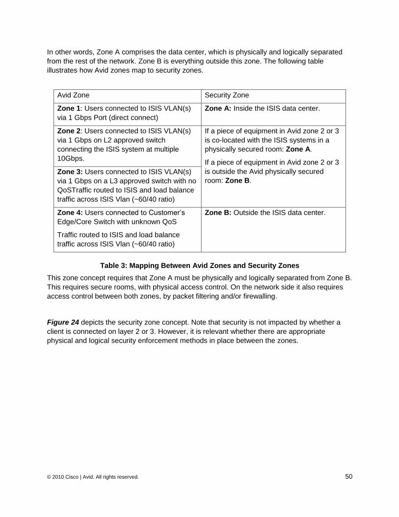
© 2010 Cisco | Avid. All rights reserved. 50
In other words, Zone A comprises the data center, which is physically and logically separated
from the rest of the network. Zone B is everything outside this zone. The following table
illustrates how Avid zones map to security zones.
Avid Zone Security Zone
Zone 1: Users connected to ISIS VLAN(s)
via 1 Gbps Port (direct connect)
Zone A: Inside the ISIS data center.
Zone 2: Users connected to ISIS VLAN(s)
via 1 Gbps on L2 approved switch
connecting the ISIS system at multiple
10Gbps.
If a piece of equipment in Avid zone 2 or 3
is co-located with the ISIS systems in a
physically secured room: Zone A.
If a piece of equipment in Avid zone 2 or 3
is outside the Avid physically secured
room: Zone B.
Zone 3: Users connected to ISIS VLAN(s)
via 1 Gbps on a L3 approved switch with no
QoSTraffic routed to ISIS and load balance
traffic across ISIS Vlan (~60/40 ratio)
Zone 4: Users connected to Customer‘s
Edge/Core Switch with unknown QoS
Traffic routed to ISIS and load balance
traffic across ISIS Vlan (~60/40 ratio)
Zone B: Outside the ISIS data center.
Table 3: Mapping Between Avid Zones and Security Zones
This zone concept requires that Zone A must be physically and logically separated from Zone B.
This requires secure rooms, with physical access control. On the network side it also requires
access control between both zones, by packet filtering and/or firewalling.
Figure 24 depicts the security zone concept. Note that security is not impacted by whether a
client is connected on layer 2 or 3. However, it is relevant whether there are appropriate
physical and logical security enforcement methods in place between the zones.
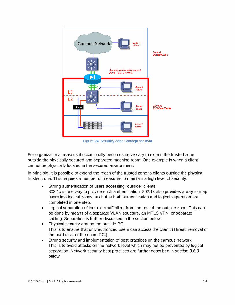
© 2010 Cisco | Avid. All rights reserved. 51
Figure 24: Security Zone Concept for Avid
For organizational reasons it occasionally becomes necessary to extend the trusted zone
outside the physically secured and separated machine room. One example is when a client
cannot be physically located in the secured environment.
In principle, it is possible to extend the reach of the trusted zone to clients outside the physical
trusted zone. This requires a number of measures to maintain a high level of security:
Strong authentication of users accessing ―outside‖ clients
802.1x is one way to provide such authentication. 802.1x also provides a way to map
users into logical zones, such that both authentication and logical separation are
completed in one step.
Logical separation of the ―external‖ client from the rest of the outside zone, This can
be done by means of a separate VLAN structure, an MPLS VPN, or separate
cabling. Separation is further discussed in the section below.
Physical security around the outside PC
This is to ensure that only authorized users can access the client. (Threat: removal of
the hard disk, or the entire PC.)
Strong security and implementation of best practices on the campus network
This is to avoid attacks on the network level which may not be prevented by logical
separation. Network security best practices are further described in section 3.6.3
below.
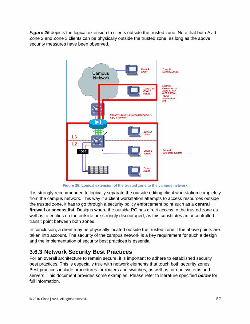
© 2010 Cisco | Avid. All rights reserved. 52
Figure 25 depicts the logical extension to clients outside the trusted zone. Note that both Avid
Zone 2 and Zone 3 clients can be physically outside the trusted zone, as long as the above
security measures have been observed.
Figure 25: Logical extension of the trusted zone to the campus network
It is strongly recommended to logically separate the outside editing client workstation completely
from the campus network. This way if a client workstation attempts to access resources outside
the trusted zone, it has to go through a security policy enforcement point such as a central
firewall or access list. Designs where the outside PC has direct access to the trusted zone as
well as to entities on the outside are strongly discouraged, as this constitutes an uncontrolled
transit point between both zones.
In conclusion, a client may be physically located outside the trusted zone if the above points are
taken into account. The security of the campus network is a key requirement for such a design
and the implementation of security best practices is essential.
3.6.3 Network Security Best Practices For an overall architecture to remain secure, it is important to adhere to established security
best practices. This is especially true with network elements that touch both security zones.
Best practices include procedures for routers and switches, as well as for end systems and
servers. This document provides some examples. Please refer to literature specified below for
full information.
© 2010 Cisco | Avid. All rights reserved. 53
Examples of security best practices are:
Physical security: To prevent theft of hard disks or flash disks, modifications of
cabling, removal of security elements, etc.
Access control: To prevent unauthorized access to PCs, routers, switches and
other devices. This includes appropriate password management, and access control
via advanced systems such as Kerberos, AAA (authentication, authorization and
accounting).
Switch security: To prevent layer-2 attacks, such as MAC spoofing, CAM table
flooding, DHCP spoofing, etc. Security is especially important on switches that touch
both security levels. Modern switches like the Cisco Catalyst 4900 or 6500 provide
the necessary security features, such as port security, DHCP snooping, dynamic
ARP inspection, and private VLANs.
Router security: To prevent security compromises on routers which could lead to
man-in-the-middle attacks, denial of service attacks, etc.
Security monitoring: To detect attack attempts, or successful attacks.
Operational security: To detect potential insider attacks or misconfigurations.
Assuming solid security is in place in the network and on a physical level, zone separation can
be successfully implemented by using firewalls and/or packet filters.
3.6.4 Zone Separation There is a control instance between two security zones which passes packets that conform to a
security policy, and drops packets that do not. This implies the existence of a security policy,
which clearly defines what is allowed between zones, in either direction, and what is not. There
are three fundamental types of control instances:
Packet filters
Firewalls
Intrusion Prevention Systems
These are discussed in the following sub-sections.
Note: At the time this document was written, no authoritative and complete list of connections in the Avid ISIS system was available. Therefore, we list various mechanisms here without giving a final recommendation on which is the best option for the Avid architecture.
3.6.4.1 Packet Filters / Access Control Lists Decisions on forwarding/dropping packet filters are made independently for each packet, and
only by looking at one direction of traffic at a time. Access control lists (ACL) are Cisco‘s
implementation of packet filters. Normal ACLs strictly consider only one direction of traffic. For
example, if a telnet connection in one direction may result in packets to a large number of
source ports in the other direction, all these possible return ports need to be allowed statically.
Reflexive ACLs improve on this: They monitor an outgoing connection, and automatically open
ingress flows with matching port numbers. This typically allows tighter security.
© 2010 Cisco | Avid. All rights reserved. 54
Cisco platforms support ACLs at full line rate as performed by hardware engines so that there is
no performance impact. ACLs do not consider packet payload, or look into the application in any
way. This typically makes them unsuitable for many multimedia applications, where port
numbers for subsequent connections are negotiated dynamically.
3.6.4.2 Firewalls A firewall examines both directions of a traffic flow, and maintains the state of each connection.
It understands application algorithms, which allows it to do things like permit new flows that are
negotiated in an existing connection. A firewall usually defaults to ―drop‖ for anything not
explicitly permitted.
Avid video frames are fragmented due to the nature of the handshake mechanism established
between the ISIS servers and the different editing clients. While the request from the editing
client is built with small sized flows, the response from the ISIS server consists of large amounts
of data (video data blocks) sent to the client in a burst of 256 Kbytes or even 512 Kbytes by
default with ISIS version 2.0. Therefore, the firewall needs to deal with fragmented packets from
the ISIS system toward the ISIS clients.
Before the firewall can validate the IP datagram, it needs to re-assemble it to its original size of
256 Kbytes or 512 Kbytes. This re-assembly takes approximately 2ms. If the frame meets the
security policies, the firewall needs to re-fragment the datagram in the same way it received it in
order to proceed to the next step. Then the firewall can send it to the outbound interface. This
second stages takes an additional 2ms. Theoretically, the total process to control the flow may
take a total of 5ms or more of additional latency.
Since the firewall is the central point for security control, it needs to deal with several
simultaneous sessions. This is especially true when multiple editing clients exchange large
amounts of data. The firewall must be able to treat a large quantity of 256 Kbytes burst per
second, which is dependent on video resolution.
DV25 runs approximately 4MB/s which is 16 x 256 Kbytes bursts per second
DV50 runs approximately 8MB/s which is 32 x 256 Kbytes burst per second
MPEG II Browse of uncompressed audio is approximately 1MB/s in 4 x 256 Kbytes
bursts per second
20 editing clients running dual-stream (a consistent ―standard‖ number in a large broadcaster
environment) would require 10MB of high speed memory available in the firewall. In order to
process at a high speed, this needs to be executed in hardware, not software which would add
huge amounts of latency. This becomes a heavy task for most firewalls, so the general
recommendation from Avid is to not firewall the ISIS video traffic.
However, instead of not protecting the ISIS installation at all, it is possible to position a firewall
and to bypass the high-bandwidth sessions. This way, the firewall does not have to analyze this
specific type of stream completely. However, other connections are still secured by the firewall.
Since the multimedia streams go from the inside (the trusted zone) to the outside, this behavior
is probably acceptable.
It is also possible to detour the firewall for specific streams using Policy-based routing (PBR).
PBR allows bypassing streams based on one of the parameters discussed below.
© 2010 Cisco | Avid. All rights reserved. 55
3.6.4.3 Selectively Bypassing a firewall with Policy Based Routing If it can be assumed that certain flows do not pose a security threat, it is possible to bypass
those flows such that they do not go through the firewall. This avoids additional firewall load, as
well as delays for the flow. Flows can be identified and diverted based on a large number of flow
parameters. In this example, the following parameters are of interest:
ISIS source address
Client destination address
UDP Port
o Ports 4200 - 4599 (since ISIS Version 1.4)
It is not possible to differentiate ISIS applications on the network level, as they all use the same
range of UDP ports. However, high-volume flows can be routed via policy based routing (PBR)
to bypass the firewall, whereas other flows can be sent through the firewall for security
enforcement.
Note: Note that all 400 ports are in use at any time, but the ports in use will vary over time over this entire dynamic range. The wide range of ports is used by ISIS as a tracking mechanism of the UDP segments that are exchanged between the ISIS server blade and the ISIS client.
If the firewall policy for a given flow is a ―permit‖ without further application-level inspection, then
a PBR bypass based on the flow parameters results in a similar protection. However, a PBR
policy is stateless, meaning that the connection will always be open. It is not dependent on a
previous connection in the other direction, the state of the TCP protocol, or other flow
parameters. Acceptance of this policy is dependent on the application.
PBR is computed in hardware (Forwarding Engine), so there is no impact in terms of
performance.
3.6.4.4 Intrusion Prevention Systems (IPS) In addition to packet filters and firewalls, Intrusion Prevention Systems (IPS) are also designed
to enforce a security boundary between two zones of trust. An IPS examines flows bi-
directionally and is stateful, like a firewall. However it typically applies a more detailed analysis
of flows to be able to do things like detect malicious payload.
An IPS typically defaults to ―permit‖. Due to the complex analysis necessary on the protocol and
payload level, IPS systems have important throughput limitations, and are therefore not the
method of choice for separating the trusted ISIS zone from the enterprise network. However,
IPS systems may add value in the general enterprise network, or possibly inside the ISIS
trusted zone, as long as the bandwidth passing through it is appropriate for the device.
3.6.5 Logical Segmentation As described above, there are cases where trusted clients are outside the trusted zone, and
should therefore be logically separated from the campus network. Segmentation can be
achieved through VLANs, MPLS VPNs, or physical cabling directly to the PC.
MPLS VPNs separate traffic at the data-link and network layer. This is so that media client
groups can only communicate with media servers and other clients within their virtual network.
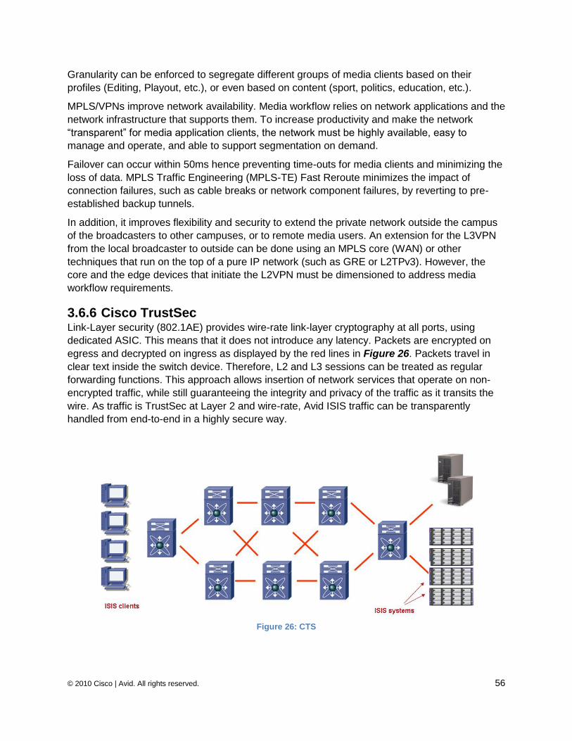
© 2010 Cisco | Avid. All rights reserved. 56
Granularity can be enforced to segregate different groups of media clients based on their
profiles (Editing, Playout, etc.), or even based on content (sport, politics, education, etc.).
MPLS/VPNs improve network availability. Media workflow relies on network applications and the
network infrastructure that supports them. To increase productivity and make the network
―transparent‖ for media application clients, the network must be highly available, easy to
manage and operate, and able to support segmentation on demand.
Failover can occur within 50ms hence preventing time-outs for media clients and minimizing the
loss of data. MPLS Traffic Engineering (MPLS-TE) Fast Reroute minimizes the impact of
connection failures, such as cable breaks or network component failures, by reverting to pre-
established backup tunnels.
In addition, it improves flexibility and security to extend the private network outside the campus
of the broadcasters to other campuses, or to remote media users. An extension for the L3VPN
from the local broadcaster to outside can be done using an MPLS core (WAN) or other
techniques that run on the top of a pure IP network (such as GRE or L2TPv3). However, the
core and the edge devices that initiate the L2VPN must be dimensioned to address media
workflow requirements.
3.6.6 Cisco TrustSec Link-Layer security (802.1AE) provides wire-rate link-layer cryptography at all ports, using
dedicated ASIC. This means that it does not introduce any latency. Packets are encrypted on
egress and decrypted on ingress as displayed by the red lines in Figure 26. Packets travel in
clear text inside the switch device. Therefore, L2 and L3 sessions can be treated as regular
forwarding functions. This approach allows insertion of network services that operate on non-
encrypted traffic, while still guaranteeing the integrity and privacy of the traffic as it transits the
wire. As traffic is TrustSec at Layer 2 and wire-rate, Avid ISIS traffic can be transparently
handled from end-to-end in a highly secure way.
Figure 26: CTS
© 2010 Cisco | Avid. All rights reserved. 57
Cisco TrustSec (CTS)
CTS is a suite of security functionality that includes End-point Authentication (EAC), Network
Device Admission Control (NDAC), Link-layer Cryptography (802.1AE) and Security Group
Access Control Lists (SGACL). The different features are closely linked to each other and
therefore Cisco TrustSec is commonly referred to as a security architecture.
Network Device Admission Control
NDAC provides the functionality necessary for Network Devices to authenticate and authorize
each other onto the network. Using 802.1x, a new network device will be authenticated and
authorized by the network device it is connecting to. This way, network devices in the Cisco
TrustSec architecture can play the role of a 802.1x Authenticator or Supplicant, depending on
the scenario. This prevents unauthorized network devices from joining the network.
End-Point Admission Control
EAC is the 802.1x (or other) authentication and authorization of an end-point as it connects to
the network. This prevents an unauthorized client from connecting to the network. NDAC and
EAC together ensure that all elements in the network, including PCs, are known and
authenticated.
Link-layer Cryptography
802.1ae standardizes cryptography at the link layer. Traffic is encrypted and decrypted every
time it goes on or off the wire. In other words, 802.1ae is hop-by-hop encryption.
There are several advantages to link-layer cryptography. The first one is scalability. Because
the only Security Association required is for a single point-to-point link, link-layer cryptography
scales much better than end-to-end encryption schemes in which states (Security Associations)
would have to be maintained for each end-point.
The second advantage is that traffic is encrypted on the wire, but is clear within the network
devices. This makes it possible to insert Network Services along an encrypted path and
maintain the necessary monitoring and visibility while providing encryption. The latter was not
possible before link-layer cryptography was made available. Encryption mechanisms are
provided by the hardware where each interface has its own ASIC that performs the encryption
at 10GE line rate.
Security Group ACLs
SGACLs are ACLs based on Security Group Tags (SGTs). Rather than defining policies based
on IP addresses, which are tightly bound to the topology, end-points can be grouped into
security groups. The end-points belong to the same groups as they move around the network
(this is achieved by dynamic authentication and tagging of the traffic with the corresponding
SGT). Policies are therefore topology-independent, as an end-point can change its IP address
but still be subject to the same policies based on its security group membership
When hosts (e.g., servers) authenticate into the network based on their identity and role, the
AAA policy server parses the authorization rules. It then determines which logical security group
the host should be assigned to and assesses if there are any SGACLs to be applied. If there are
SGACLs which have been assigned in the matrix for the given security group, then those
SGACLs will be dynamically downloaded and applied on the switch for any communications
destined to that host. This provides dynamic policy provisioning that is associated with the host
© 2010 Cisco | Avid. All rights reserved. 58
based on its identity and network role. Again this is accommodated without any knowledge of
the host‘s IP address, subnet or VLAN.
3.6.7 Security Management and Monitoring Security is a fundamental function in a network which needs to be managed, as well as
monitored, just like any other network functionality.
Security management includes the control of user and network device credentials in a scalable
and secure way. Authentication, authorization and accounting (AAA) servers are a fundamental
part of credential management. Additionally, security elements such as firewalls need to be
securely and easily managed. This usually involves management software such as Cisco
Security Manager (CSM).
Monitoring is an essential part of overall security management. The goal is to be able to detect
security problems, such as potential intrusions or denial of service attacks. Network
management platforms usually include an element of monitoring, but there are also special
monitoring solutions for security, such as CS-MARS. Such solutions obtain network intelligence
in a number of ways (e.g., through syslog, NetFlow, and SNMP traps). They correlate
information from various devices and provide a network-wide view of a potential security issue
to the operator.
Security management and monitoring are essential in an Avid data center and campus network,
and must be considered in the security design.
© 2010 Cisco | Avid. All rights reserved. 59
3.7 Increased Network High Availability High Availability continues to be a major requirement for the different network building blocks
that exist in the enterprise infrastructure. The target for HA is 99.999% uptime, with only five
minutes of downtime permitted per year. HA must be addressed through advanced
technologies. Even if most Layer 2 and Layer 3 protocols provide a certain level of redundant
elements by nature, this generally is not sufficient to reach the high level of availability required
by most enterprises today.
The expectations for high availability are evolving. A highly available network infrastructure
requires switch-level and architecture-level high availability. Therefore, it is important to address
these independently but cohesively. Switch-level high availability is addressed by hardware and
software architectures and the capabilities they offer.
Cisco offers a set of enhancements for standard L2 (UDLD, Loop Guard, Root Guard, and new
RSTP dispute mechanisms, bridge assurance and other Port VLAN ID mismatch controls) and
L3 resilient architectures (fast IP convergence, BFD).
Network node virtualization is another new advanced technology for network node redundancy
(Virtual Switching Systems, Virtual Port Channel, MAC pinning). This virtualization combines
multiple physical devices and links into one single logical redundant element.
Data center network high availability focuses on bandwidth and path optimization, reliability,
stability, and deterministic behavior. All of these need to be taken under consideration during
steady state and through normal operational procedures and failover conditions.
This document is not intended to cover all these features and enhancements in detail. However,
it is important to highlight some of the new components that offer node virtualization and
therefore enforce High Availability while improving the bandwidth as well as the shortest path.
The node or switch virtualization is characterized using two distinct node virtualizations:
Many-to-One – This is addressed with the Virtual Switch System supported on the
Cisco Catalyst 6500 in conjunction with the Sup720-10GE series
One-to-Many – This addresses the Virtual Device Context supported by the
Cisco Nexus 7000 series
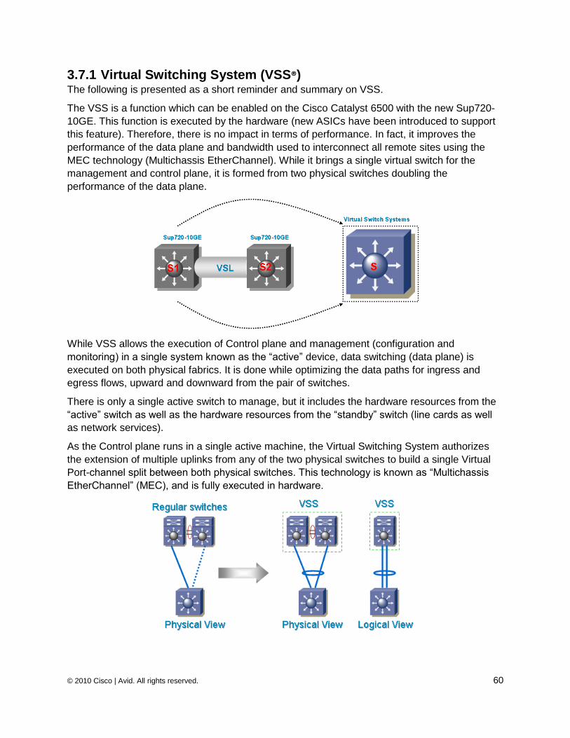
© 2010 Cisco | Avid. All rights reserved. 60
3.7.1 Virtual Switching System (VSS®) The following is presented as a short reminder and summary on VSS.
The VSS is a function which can be enabled on the Cisco Catalyst 6500 with the new Sup720-
10GE. This function is executed by the hardware (new ASICs have been introduced to support
this feature). Therefore, there is no impact in terms of performance. In fact, it improves the
performance of the data plane and bandwidth used to interconnect all remote sites using the
MEC technology (Multichassis EtherChannel). While it brings a single virtual switch for the
management and control plane, it is formed from two physical switches doubling the
performance of the data plane.
While VSS allows the execution of Control plane and management (configuration and
monitoring) in a single system known as the ―active‖ device, data switching (data plane) is
executed on both physical fabrics. It is done while optimizing the data paths for ingress and
egress flows, upward and downward from the pair of switches.
There is only a single active switch to manage, but it includes the hardware resources from the
―active‖ switch as well as the hardware resources from the ―standby‖ switch (line cards as well
as network services).
As the Control plane runs in a single active machine, the Virtual Switching System authorizes
the extension of multiple uplinks from any of the two physical switches to build a single Virtual
Port-channel split between both physical switches. This technology is known as ―Multichassis
EtherChannel‖ (MEC), and is fully executed in hardware.
© 2010 Cisco | Avid. All rights reserved. 61
In a regular design, the server is usually connected in a dual-homed manner to offer a high level
of redundancy on the network server side. However, only one server NIC can be forwarding at a
time due to the teaming mechanism. The same scenario occurs between the access and the
aggregation layer. A second path is available to provide a redundant path in case of failure on
the aggregation or distribution layer or uplink. In a normal layer 2 design, it is not acceptable to
have two different paths due to the infinite L2 loop. Therefore, the Spanning Tree Protocol will
force all the links for the same path to become backup except one.
The PortChannel (aka PAgP or LACP) provides up to 8 physical links that operate all together in
parallel. However the biggest limitation in classic PortChannel is that the PortChannel operates
only between two devices in point to point configuration.
To address this limitation, the Virtual Switch System provides a technology called MEC that
distributes the Port-channel from a single device (either a server or a switch) into two different
physical switches, yet they appear as one single but logical switch.
Very similar features are also offered with the Stackwize concept (aka cat3750) or the Virtual
Blade Switches (aka VBS-31xx)
3.7.2 Virtual Port Channel (vPC) The Cisco Nexus 7000 as well as Nexus 5000 offers a very similar concept to the MultiChassis
EtherChannel (MEC) available with the VSS. This function is called Virtual Port-channel (vPC)
or sometime MultiChassis EtherChannel (MCEC). To avoid any confusion with MEC, we will call
a logical PortChannel of the VSS a MEC and the virtual PortChannel of the Cisco Nexus 7000 a
vPC. A pair of Cisco Nexus 7000 switches acting as a vPC peer endpoint looks like a single
logical entity to PortChannel-attached devices, yet the two devices that act as the logical
PortChannel endpoint are still two separate devices. This environment combines the benefits of
hardware redundancy with the benefits of PortChannel loop management. The other main
benefit of migration to an all-PortChannel-based loop management mechanism is that link
recovery is potentially much faster. Spanning Tree Protocol can recover from a link failure in
approximately 1 second or few more depending on the spanning tree diameter, while an all-
PortChannel-based solution has the potential for failure recovery in less than a second.
It is possible to use vPC on a per VDC basis to support layer 2 multipathing for each virtual
device context, offering a full HA design for virtual segmented contexts.
Please for more details on Cisco Virtualization and High Availability, please refer to the
documents listed at the reference section: Cisco Systems
3.7.3 Virtual Device Context (VDC ) Cisco Nexus 7000 Series switches can be segmented into virtual devices based on business
need. The Virtual Device Contexts (VDC‘s) deliver true segmentation of network traffic, context-
level fault isolation, and management through the creation of independent hardware and
software partitions.
The segmentation of the Layer 1 can be done on the fly without impacting the production
network. Any line card and interface can be part of one VDC.
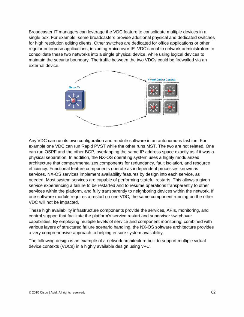
© 2010 Cisco | Avid. All rights reserved. 62
Broadcaster IT managers can leverage the VDC feature to consolidate multiple devices in a
single box. For example, some broadcasters provide additional physical and dedicated switches
for high resolution editing clients. Other switches are dedicated for office applications or other
regular enterprise applications, including Voice over IP. VDC‘s enable network administrators to
consolidate these two networks into a single physical device, while using logical devices to
maintain the security boundary. The traffic between the two VDCs could be firewalled via an
external device.
Any VDC can run its own configuration and module software in an autonomous fashion. For
example one VDC can run Rapid PVST while the other runs MST. The two are not related. One
can run OSPF and the other BGP, overlapping the same IP address space exactly as if it was a
physical separation. In addition, the NX-OS operating system uses a highly modularized
architecture that compartmentalizes components for redundancy, fault isolation, and resource
efficiency. Functional feature components operate as independent processes known as
services. NX-OS services implement availability features by design into each service, as
needed. Most system services are capable of performing stateful restarts. This allows a given
service experiencing a failure to be restarted and to resume operations transparently to other
services within the platform, and fully transparently to neighboring devices within the network. If
one software module requires a restart on one VDC, the same component running on the other
VDC will not be impacted.
These high availability infrastructure components provide the services, APIs, monitoring, and
control support that facilitate the platform‘s service restart and supervisor switchover
capabilities. By employing multiple levels of service and component monitoring, combined with
various layers of structured failure scenario handling, the NX-OS software architecture provides
a very comprehensive approach to helping ensure system availability.
The following design is an example of a network architecture built to support multiple virtual
device contexts (VDCs) in a highly available design using vPC.
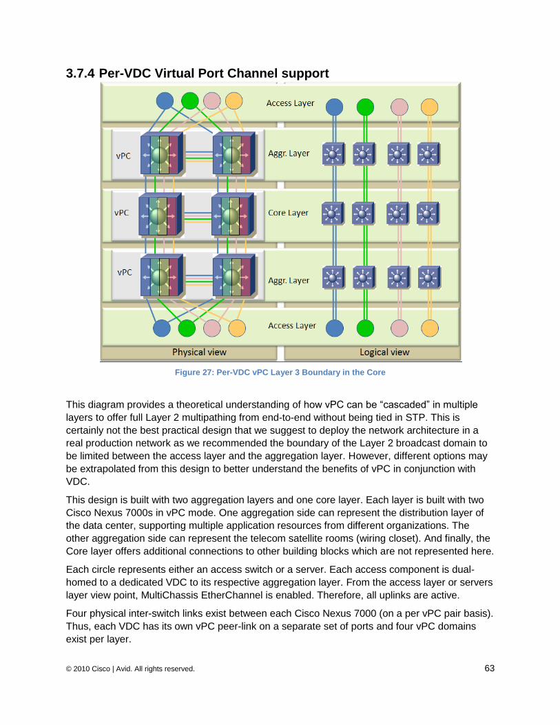
© 2010 Cisco | Avid. All rights reserved. 63
3.7.4 Per-VDC Virtual Port Channel support
Figure 27: Per-VDC vPC Layer 3 Boundary in the Core
This diagram provides a theoretical understanding of how vPC can be ―cascaded‖ in multiple
layers to offer full Layer 2 multipathing from end-to-end without being tied in STP. This is
certainly not the best practical design that we suggest to deploy the network architecture in a
real production network as we recommended the boundary of the Layer 2 broadcast domain to
be limited between the access layer and the aggregation layer. However, different options may
be extrapolated from this design to better understand the benefits of vPC in conjunction with
VDC.
This design is built with two aggregation layers and one core layer. Each layer is built with two
Cisco Nexus 7000s in vPC mode. One aggregation side can represent the distribution layer of
the data center, supporting multiple application resources from different organizations. The
other aggregation side can represent the telecom satellite rooms (wiring closet). And finally, the
Core layer offers additional connections to other building blocks which are not represented here.
Each circle represents either an access switch or a server. Each access component is dual-
homed to a dedicated VDC to its respective aggregation layer. From the access layer or servers
layer view point, MultiChassis EtherChannel is enabled. Therefore, all uplinks are active.
Four physical inter-switch links exist between each Cisco Nexus 7000 (on a per vPC pair basis).
Thus, each VDC has its own vPC peer-link on a separate set of ports and four vPC domains
exist per layer.
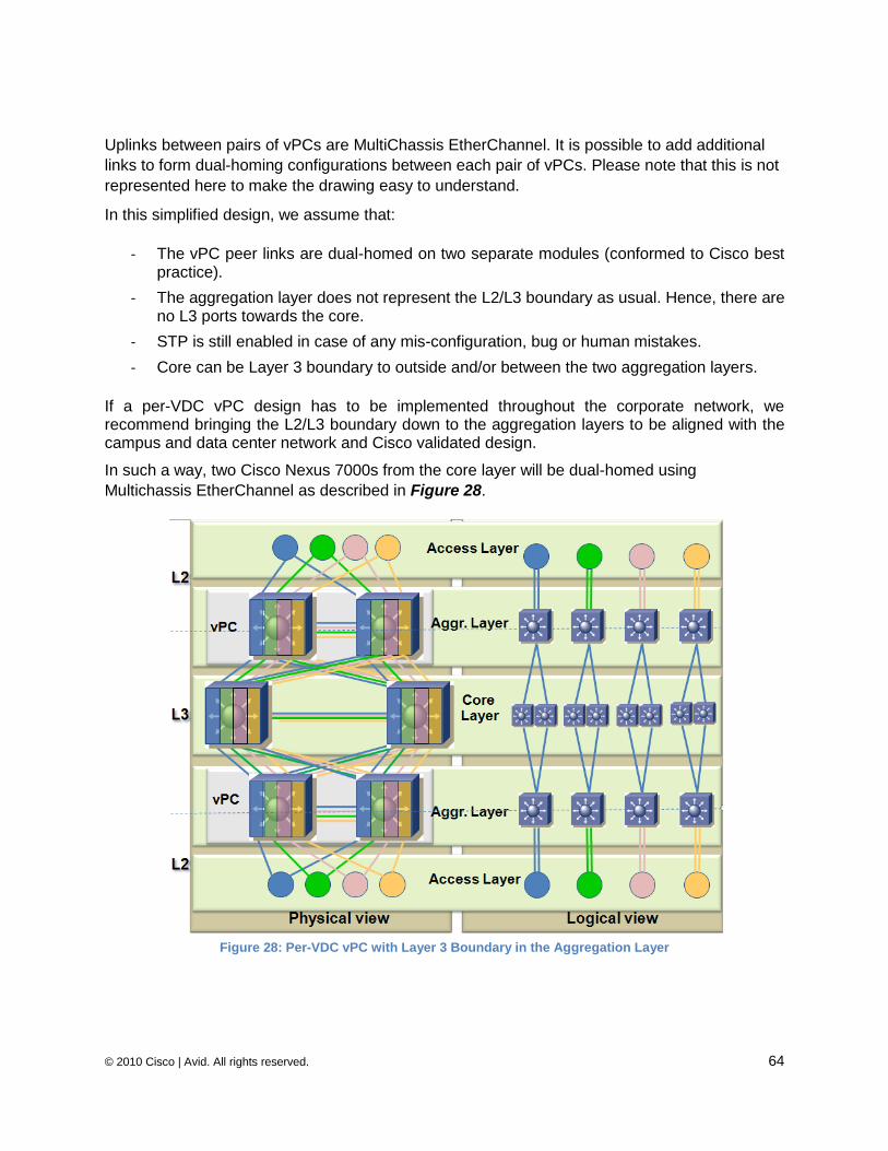
© 2010 Cisco | Avid. All rights reserved. 64
Uplinks between pairs of vPCs are MultiChassis EtherChannel. It is possible to add additional
links to form dual-homing configurations between each pair of vPCs. Please note that this is not
represented here to make the drawing easy to understand.
In this simplified design, we assume that:
- The vPC peer links are dual-homed on two separate modules (conformed to Cisco best practice).
- The aggregation layer does not represent the L2/L3 boundary as usual. Hence, there are no L3 ports towards the core.
- STP is still enabled in case of any mis-configuration, bug or human mistakes.
- Core can be Layer 3 boundary to outside and/or between the two aggregation layers.
If a per-VDC vPC design has to be implemented throughout the corporate network, we recommend bringing the L2/L3 boundary down to the aggregation layers to be aligned with the campus and data center network and Cisco validated design.
In such a way, two Cisco Nexus 7000s from the core layer will be dual-homed using
Multichassis EtherChannel as described in Figure 28.
Figure 28: Per-VDC vPC with Layer 3 Boundary in the Aggregation Layer
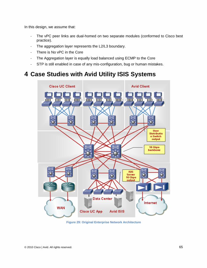
© 2010 Cisco | Avid. All rights reserved. 65
In this design, we assume that:
- The vPC peer links are dual-homed on two separate modules (conformed to Cisco best practice).
- The aggregation layer represents the L2/L3 boundary.
- There is No vPC in the Core
- The Aggregation layer is equally load balanced using ECMP to the Core
- STP is still enabled in case of any mis-configuration, bug or human mistakes.
4 Case Studies with Avid Utility ISIS Systems
Figure 29: Original Enterprise Network Architecture
© 2010 Cisco | Avid. All rights reserved. 66
4.1 Original Enterprise Network Architecture
Figure 29 provides an example of a regular network architecture deployed in a large enterprise
that is going to be used to converge the Media Workflow for a Broadcaster with the regular
applications. All access layer switches are linked to the upstream layer (aggregation switches)
using a 1GE uplinks.
Summary of Network Architecture deployment:
8000+ users on one campus
50 wiring closets, each with two Cisco Catalyst 6500s
Gigabit Ethernet from access to distribution switches
10 Gigabit Ethernet connections from distribution to core, and from core to server distribution
Fully redundant architecture
– Requirement: live editing of broadcast video anywhere
– Requirement: direct attachment of digital cameras for broadcast video anywhere
– Requirement: IP phones everywhere with Inline Power
Each wiring closet has a mixture of 6548 and 6748 boards to accommodate both of the above requirements
This architecture has been designed to successfully address the regular Enterprise workflow.
However, in the state shown it does not necessarily support all requirements for efficiently
carrying Media Workflow.
Assuming the Broadcaster network infrastructure is built on top of an existing large network
architecture, this network infrastructure is dimensioned to support several thousand users on
the same campus organized into three tier layers:
The 10GE Core layer
The Aggregation layer attached to the Core via 10GE uplinks
The Access Layer (or wiring closets) attached to the Aggregation layer using
1GE uplinks
Although the Core is interconnected with the next direct layer (aggregation layer) using 10GE
line rate links, this architecture is not necessarily laid out to support multiple video clients. The
main reason is that several video clients can be attached to the same edge switch dual-homed
with 1GE uplinks to two distribution switches. The issue is not the performance of the
distribution switch, nor the edge switch, but the upstream connection resources from the
distribution switch.
As explained in Section 3.4.5, no more than four or eight editing workstations (single stream)
can be supported per edge switch. Each single video data block uses a UDP burst of 256Kbytes
or 512Kbytes, and the maximum buffer capacity available per uplink interface is 2.3MB (2 x
© 2010 Cisco | Avid. All rights reserved. 67
1.16MB). Therefore, theoretically, no more than 4 or 8 editors can be supported at a time,
assuming all editing clients use a single video stream.
However, in a real production network it is not unusual to see clients running two or more
concurrent video streams. This reduces the maximum number of clients able to edit video
streams concurrently.
The buffer resources may also be limited by the use of QoS queuing for other applications like
IPT or collaboration tools that would require additional QoS.
The user experience is very bad when multiple NLE clients are operating from the same switch
with multiple DV50 streams. In order to accommodate the Avid NLE clients, the video queue
would require 80% of available queue space. As a result, ordinary shared applications such FTP
suffer dramatically from this buffer resource allocation.
Therefore, although this network architecture fits perfectly for ―regular‖ enterprise applications, it
is not well suited for media broadcaster client server applications using high resolution.
The 6748 line cards have fixed buffers of 1,16MB RAM per port which is a deliberate
hardware design, reducing the critical latency to a minimum.
In a worst-case scenario, the volume of burst data is larger than the total size of
buffer in the timeframe of the burst minus depletion rate which implies packets are
dropped.
The Avid NLE application uses approximately 52 Kbyte datagrams, consisting of
approximately 35 Ethernet frames of 1500Bytes each. If one of these frames is
dropped, the entire datagram is dropped and retransmitted, resulting in low
throughput / performance and adding more unnecessary traffic.
Cisco Catalyst 6500 switches can enable QoS with advanced buffering and queuing
mechanisms. This can protect data from being dropped if links are over-subscribed. However,
only a finite amount of buffering is available to each port. If that buffer is overrun by an extended
period of over-subscription, data will be dropped anyhow.
If we concentrate on the areas of concern to media applications, servers on the data center
layer and clients on the wiring closets or access layer, and assume the Core layer is a non-
blocking 10GE, each building block needs to be optimized.
4.2 Protocol Optimization By nature of the ISIS application, the media flows exchanged from the servers to the ISIS clients
oversubscribe the network bandwidth, which may induce packet loss. The protocol doesn't
efficiently handle packet loss (UDP) at the ISIS application layer, which causes large amounts
of retransmission (further increasing traffic by retransmitting each complete datagram for each
packet loss).
First, the application flow cannot be optimized so that it doesn‘t oversubscribe the
client bandwidth, or at least lower the oversubscription. The servers will reply to the
client as fast as they can. Therefore, it is not really possible to scale the complete
network architecture for an unlimited number of video clients. Such scaling can only
be accomplished for local connections.
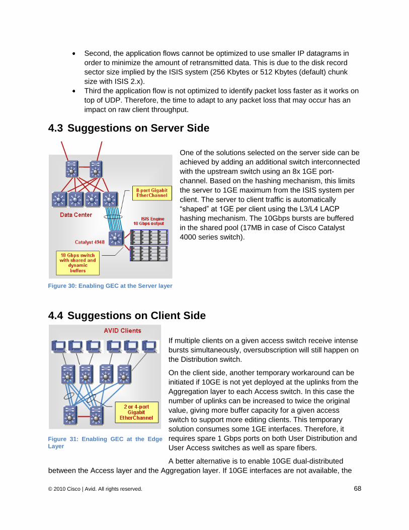
© 2010 Cisco | Avid. All rights reserved. 68
Second, the application flows cannot be optimized to use smaller IP datagrams in
order to minimize the amount of retransmitted data. This is due to the disk record
sector size implied by the ISIS system (256 Kbytes or 512 Kbytes (default) chunk
size with ISIS 2.x).
Third the application flow is not optimized to identify packet loss faster as it works on
top of UDP. Therefore, the time to adapt to any packet loss that may occur has an
impact on raw client throughput.
4.3 Suggestions on Server Side
One of the solutions selected on the server side can be
achieved by adding an additional switch interconnected
with the upstream switch using an 8x 1GE port-
channel. Based on the hashing mechanism, this limits
the server to 1GE maximum from the ISIS system per
client. The server to client traffic is automatically
―shaped‖ at 1GE per client using the L3/L4 LACP
hashing mechanism. The 10Gbps bursts are buffered
in the shared pool (17MB in case of Cisco Catalyst
4000 series switch).
4.4 Suggestions on Client Side
If multiple clients on a given access switch receive intense
bursts simultaneously, oversubscription will still happen on
the Distribution switch.
On the client side, another temporary workaround can be
initiated if 10GE is not yet deployed at the uplinks from the
Aggregation layer to each Access switch. In this case the
number of uplinks can be increased to twice the original
value, giving more buffer capacity for a given access
switch to support more editing clients. This temporary
solution consumes some 1GE interfaces. Therefore, it
requires spare 1 Gbps ports on both User Distribution and
User Access switches as well as spare fibers.
A better alternative is to enable 10GE dual-distributed
between the Access layer and the Aggregation layer. If 10GE interfaces are not available, the
Figure 30: Enabling GEC at the Server layer
Figure 31: Enabling GEC at the Edge
Layer
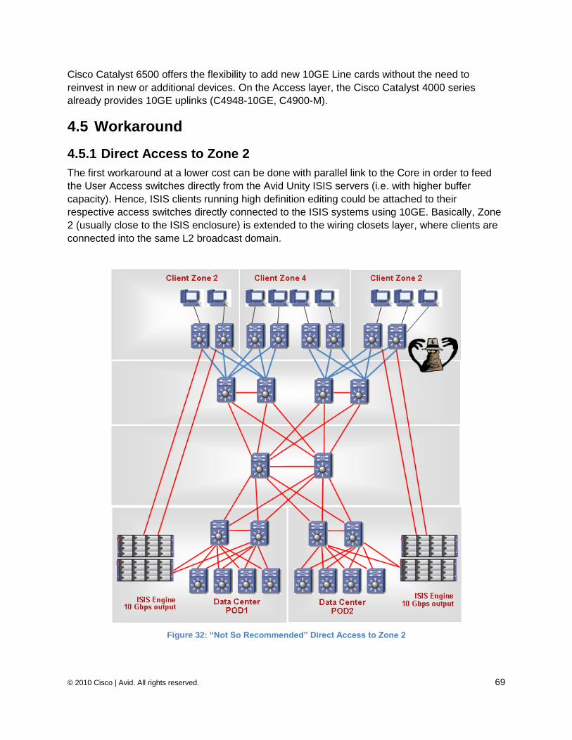
© 2010 Cisco | Avid. All rights reserved. 69
Cisco Catalyst 6500 offers the flexibility to add new 10GE Line cards without the need to
reinvest in new or additional devices. On the Access layer, the Cisco Catalyst 4000 series
already provides 10GE uplinks (C4948-10GE, C4900-M).
4.5 Workaround
4.5.1 Direct Access to Zone 2
The first workaround at a lower cost can be done with parallel link to the Core in order to feed
the User Access switches directly from the Avid Unity ISIS servers (i.e. with higher buffer
capacity). Hence, ISIS clients running high definition editing could be attached to their
respective access switches directly connected to the ISIS systems using 10GE. Basically, Zone
2 (usually close to the ISIS enclosure) is extended to the wiring closets layer, where clients are
connected into the same L2 broadcast domain.
Figure 32: “Not So Recommended” Direct Access to Zone 2
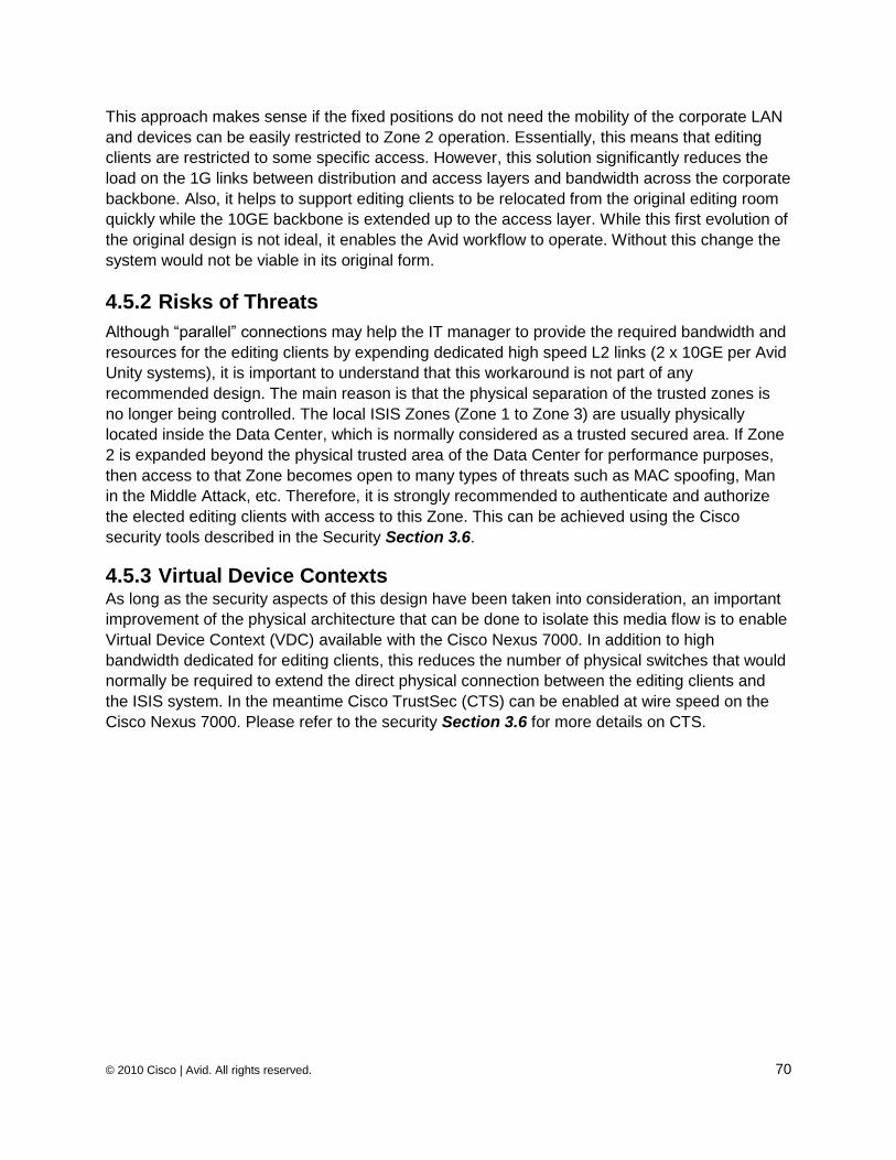
© 2010 Cisco | Avid. All rights reserved. 70
This approach makes sense if the fixed positions do not need the mobility of the corporate LAN
and devices can be easily restricted to Zone 2 operation. Essentially, this means that editing
clients are restricted to some specific access. However, this solution significantly reduces the
load on the 1G links between distribution and access layers and bandwidth across the corporate
backbone. Also, it helps to support editing clients to be relocated from the original editing room
quickly while the 10GE backbone is extended up to the access layer. While this first evolution of
the original design is not ideal, it enables the Avid workflow to operate. Without this change the
system would not be viable in its original form.
4.5.2 Risks of Threats
Although ―parallel‖ connections may help the IT manager to provide the required bandwidth and
resources for the editing clients by expending dedicated high speed L2 links (2 x 10GE per Avid
Unity systems), it is important to understand that this workaround is not part of any
recommended design. The main reason is that the physical separation of the trusted zones is
no longer being controlled. The local ISIS Zones (Zone 1 to Zone 3) are usually physically
located inside the Data Center, which is normally considered as a trusted secured area. If Zone
2 is expanded beyond the physical trusted area of the Data Center for performance purposes,
then access to that Zone becomes open to many types of threats such as MAC spoofing, Man
in the Middle Attack, etc. Therefore, it is strongly recommended to authenticate and authorize
the elected editing clients with access to this Zone. This can be achieved using the Cisco
security tools described in the Security Section 3.6.
4.5.3 Virtual Device Contexts As long as the security aspects of this design have been taken into consideration, an important
improvement of the physical architecture that can be done to isolate this media flow is to enable
Virtual Device Context (VDC) available with the Cisco Nexus 7000. In addition to high
bandwidth dedicated for editing clients, this reduces the number of physical switches that would
normally be required to extend the direct physical connection between the editing clients and
the ISIS system. In the meantime Cisco TrustSec (CTS) can be enabled at wire speed on the
Cisco Nexus 7000. Please refer to the security Section 3.6 for more details on CTS.
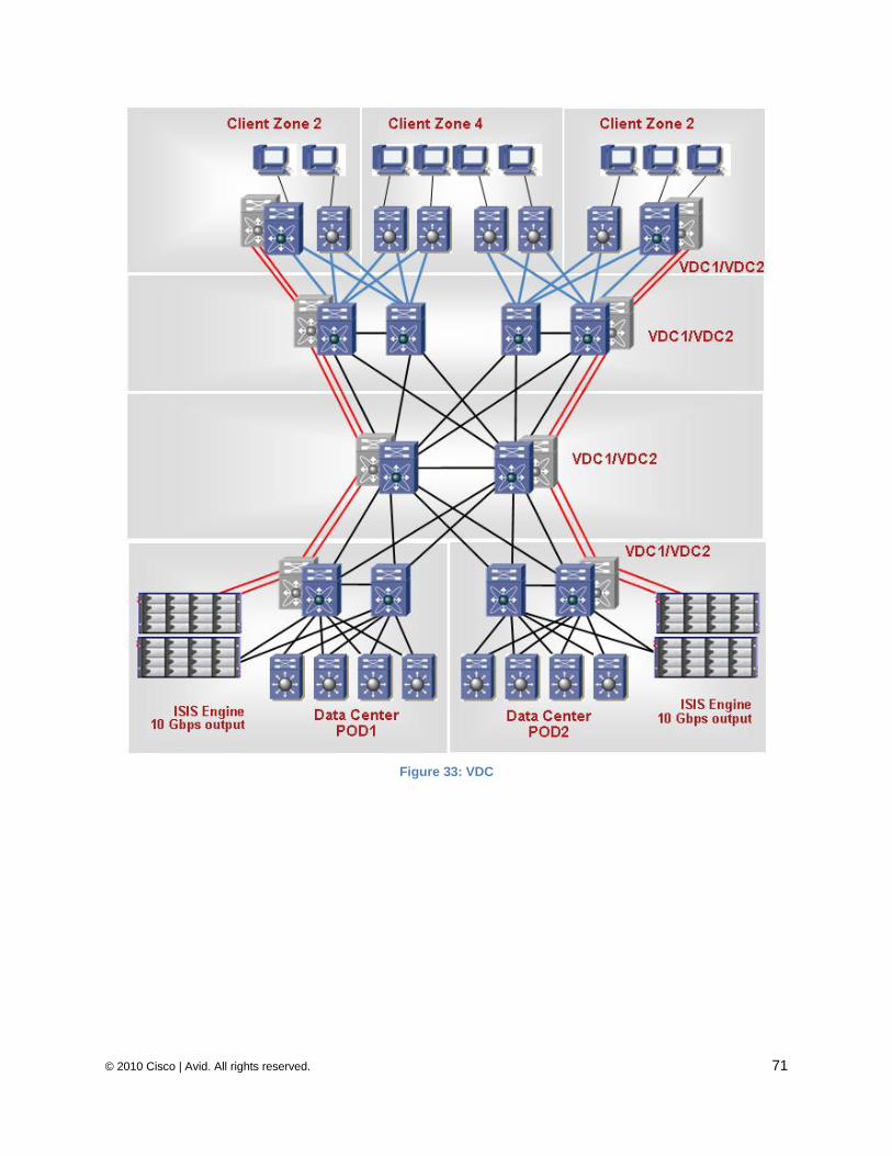
© 2010 Cisco | Avid. All rights reserved. 71
Figure 33: VDC
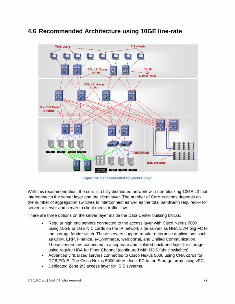
© 2010 Cisco | Avid. All rights reserved. 72
4.6 Recommended Architecture using 10GE line-rate
Figure 34: Recommended Physical Design
With this recommendation, the core is a fully distributed network with non-blocking 10GE L3 that
interconnects the server layer and the client layer. The number of Core switches depends on
the number of aggregation switches to interconnect as well as the total bandwidth required— for
server to server and server to client media traffic flow.
There are three options on the server layer inside the Data Center building blocks:
Regular high end servers connected to the access layer with Cisco Nexus 7000
using 10GE or 1GE NIC cards on the IP network side as well as HBA 1/2/4 Gig FC to
the storage fabric switch. These servers support regular enterprise applications such
as CRM, ERP, Finance, e-Commerce, web portal, and Unified Communication.
These servers are connected to a separate and isolated back-end layer for storage
using regular HBA for Fiber Channel (configured with MDS fabric switches)
Advanced virtualized servers connected to Cisco Nexus 5000 using CNA cards for
DCB/FCoE. The Cisco Nexus 5000 offers direct FC to the Storage array using vPC.
Dedicated Zone 2/3 access layer for ISIS systems.
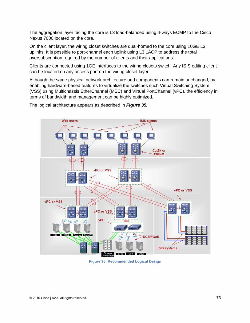
© 2010 Cisco | Avid. All rights reserved. 73
The aggregation layer facing the core is L3 load-balanced using 4-ways ECMP to the Cisco
Nexus 7000 located on the core.
On the client layer, the wiring closet switches are dual-homed to the core using 10GE L3
uplinks. It is possible to port-channel each uplink using L3 LACP to address the total
oversubscription required by the number of clients and their applications.
Clients are connected using 1GE interfaces to the wiring closets switch. Any ISIS editing client
can be located on any access port on the wiring closet layer.
Although the same physical network architecture and components can remain unchanged, by
enabling hardware-based features to virtualize the switches such Virtual Switching System
(VSS) using Multichassis EtherChannel (MEC) and Virtual PortChannel (vPC), the efficiency in
terms of bandwidth and management can be highly optimized.
The logical architecture appears as described in Figure 35.
Figure 35: Recommended Logical Design
© 2010 Cisco | Avid. All rights reserved. 74
The two main advantages of enabling Virtual PortChannel (MEC and VSS) are:
First to optimize all uplink utilization by enabling LACP distributed across a pair of
upstream chassis (also known as V shape from a Cisco recommended design)
instead of the regular Rapid STP.
Secondly, although it is recommended to keep STP enabled to protect against any
risks of L2 loop failure, the failover of all active paths is controlled by the port-channel
mechanism as if it were the regular back-to-back EtherChannel. Therefore, failover
can be achieved in a sub-second. In addition, from a deployment and
troubleshooting point of view, management operations are easier.
5 Media, Satellite and Broadcast While this document focuses on Media Workflow Platforms and provides the Cisco and Avid
network design recommendations to support Broadcaster applications in the post-production
stage, there are subsequent key video delivery processes—Contribution and Distribution.
There is a Media, Satellite and Broadcast (MSB) architecture document addressing Contribution
and Distribution, with a particular focus on Contribution processes. It provides a coherent and
unified view as to how to approach the specific activities that make up MSB offerings to
customers and the markets they serve. It provides an overview of the architectural approaches
that are proposed to address these areas. Another goal of this effort is to identify the
architectures and technologies that provide comprehensive formulas in serving our customers in
the MSB area.
For further details about Media, Satellite and Broadcast please go to:
http://www.cisco.com/en/US/netsol/ns898/networking_solutions_market_segment_solution.html
6 Summary
The recommendations presented in this document cover the IP side of the network architecture
for all types of workflows used for Avid production and post-production stages. All of the
recommendations presented are based on available Cisco Ethernet switches, including the new
generation of switches such as the Cisco Nexus 7000 and Nexus 5000 series switches. They
conform to Ethernet and IP standards and as such they interoperate with other standard
switches. As previously noted in this document, at time of publication these two switches are
not yet fully qualified or approved by Avid.
This white paper describes ways of delivering availability, resilience and performance for the
Media workflows.
Bandwidth and memory capacity requirements
Because of its native ―ultra‖ real-time workflow, bandwidth requirements differ based on the
resolutions required by each application. Different requirements can be seen for ingest, editing,
and play-out for server-to-client and server-to-server communications. It should also be noted
© 2010 Cisco | Avid. All rights reserved. 75
that the media flows exchanged between the servers and the editing clients are fundamentally
different than standard FTP transfers. They are mostly block-based and not file-based, although
some file-based transfers do exist in Avid workflows. A client may request a certain block, but
they can only request the next block if they have fully received the previous block. Avid
applications deliver bursts of data. Application throughput is conditioned by how long a complete
block needs to travel through the network. Therefore, speed and memory capacity for egress
traffic are extremely important for efficiency. In a lossless design such as a reliable campus
LAN, this solution offers very high performance for the NAS applications such Avid Unity ISIS.
Thus our recommendations to enable 10GE from the ISIS rack down to the wiring closet (user
access switches).
Security Media workflows are very sensitive to latency and jitter, so it is not recommended to insert any
stateful deep inspection devices between the client and Avid Unity ISIS servers. However, as
long as the editors can be located anywhere in a campus network, non-trusted zones must be
protected against Denial of Service, Theft of Service and Integrity attacks.
Quality of Service
The amount and resolution of media real-time traffic is typically of a higher order of magnitude
than those found in regular business networks. Therefore, the impact of uncontrolled QoS
elements is very important—especially when Media flows share the same infrastructure as
regular office applications such as CRM, ERP, Finance, e-Commerce, web portal, IP
Telephony, and Unified Communication. The key factors determining end-to-end network
transmission quality are ―packet loss‖, ―end-to-end latency‖ and induced ―jitter‖. Therefore QoS
is very important and must be enabled throughout Zone 4.
Operating the Media Workflow Platform
It is very important to be able to provide information to IT management to allow them to
accurately provision for the number of editors and video streams required at the edge layer.
This is especially the case when the network is also transporting regular office applications.
Traffic must be identified at different layers in the network architecture. The IT manager must be
able to identify the utilization of the network and memory resources available from an end-to-
end basis. Therefore, measurements and analyses must be available in real-time. High latency,
packet loss, and delay may have a very important impact in the media workflows. They must be
measured in real-time and notifications and statistics must be available for provisioning
capacity, optimizations and troubleshooting.
© 2010 Cisco | Avid. All rights reserved. 76
7 References
7.1 Avid systems
7.1.1 Network Requirements
Network Requirements for Avid Unity ISIS and Interplay
http://avid.custkb.com/avid/app/selfservice/search.jsp?DocId=244197
In addition TCP/IP Network Ports used by Avid Interplay, Avid Unity ISIS, Workgroups 4 and
other applications
http://avid.custkb.com/avid/app/selfservice/search.jsp?DocId=243397
Avid Products and Network Site Preparation Guide
http://avid.custkb.com/avid/app/selfservice/search.jsp?DocId=275203
Avid Unity ISIS Qualified Ethernet Switch Reference Guide
http://avid.custkb.com/avid/app/selfservice/search.jsp?DocId=278049
7.1.2 Applications
Interplay
http://www.avid.com/products/interplay/
http://www.avid.com/resources/briefs/interplay_sb.pdf
AirSpeed
http://www.avid.com/resources/briefs/AirSpeed.pdf
Media Composer
http://www.avid.com/products/productBriefs/Avid_MCsoftware_US_v1.pdf
Symphony
http://www.avid.com/products/productBriefs/SymphNit_US.pdf
Media Composer, Symphony, and I/O options
http://www.avid.com/products/professionalfilm_matrix.asp
iNEWS
http://www.avid.com/products/iNews/index.asp
iNEWS Instinct
http://www.avid.com/resources/briefs/inewsinstinct.pdf
© 2010 Cisco | Avid. All rights reserved. 77
NewsCutter
http://www.avid.com/products/NewsCutter-Software/index.asp
Avid Unity ISIS Admin v1.x
o Avid Unity ISIS ReadMe document v1.7
http://avid.custkb.com/avid/app/selfservice/search.jsp?DocId=288705
o Avid Unity ISIS Administration Guide v1.x
http://avid.custkb.com/avid/app/selfservice/search.jsp?DocId=265657
Avid Unity ISIS Performance Guide v1.x
http://avid.custkb.com/avid/app/selfservice/search.jsp?DocId=288705
ISIS Client Performance Testing and Troubleshooting version 2
http://avid.custkb.com/avid/app/selfservice/search.jsp?DocId=245079
7.1.3 Avid Unity ISIS v2.0
Avid provided recently a new version of Avid Unity ISIS v2.0.1. Have a look on new features
supported described on the ReadMe document
http://avid.custkb.com/avid/app/selfservice/search.jsp?DocId=287071
Avid Unity ISIS Administration Guide v2.x
http://avid.custkb.com/avid/app/selfservice/search.jsp?DocId=275227
Avid Unity ISIS Performance Guide v2.x
http://avid.custkb.com/avid/app/selfservice/search.jsp?DocId=275215
7.2 Cisco Systems
7.2.1 Switches and Reference Design Guides
Data Centre recommendation summary: Using Cisco Catalyst 6500 and Nexus 7000 Series
Switching
Please refer to the Architecture Brief white paper: Using Cisco Cisco Catalyst 6500 and Cisco
Nexus 7000 Series Switching Technology in Data Centre Networks
High Availability
Please refer to the Continuous Operation and High Availability discussion around the Cisco
Nexus 7000
© 2010 Cisco | Avid. All rights reserved. 78
Cisco Nexus 7000
Please refer to the public Cisco web page as well as a series of white papers
Cisco Validated Design for the Cisco Nexus 7000
Please refer to the DataCenter Design – IP Network Infrastructure
7.2.2 QoS and MPLS MPLS VPN Design and Implementation Guides
http://www.cisco.com/en/US/docs/solutions/Enterprise/WAN_and_MAN/ngmane.html
NBAR performance analysis
http://www.cisco.com/en/US/technologies/tk543/tk759/technologies_white_paper0900aecd8031
b712_ps6616_Products_White_Paper.html
7.2.3 Security TrustSec:
http://www.cisco.com/go/trustsec/
Secure network design guides:
http://www.cisco.com/en/US/netsol/ns744/networking_solutions_program_home.html
Cisco Security Manager (CSM):
http://www.cisco.com/en/US/products/ps6498/index.html
Cisco MARS:
http://www.cisco.com/go/mars/
7.2.4 Unified I/O, Unified Fabric and Fabric Extenders Cisco Nexus 5000 Overview
http://www.cisco.com/en/US/products/ps9670/index.html
Cisco Nexus 5000 Series Architecture
http://www.cisco.com/en/US/prod/collateral/switches/ps9441/ps9670/white_paper_c11-
462176.html
Evolving Data Center Architecture with Cisco Nexus 5000 series switches
http://www.cisco.com/en/US/solutions/collateral/ns340/ns517/ns224/ns783/white_paper_c11-
473501.html
Cisco, the Cisco logo, and Cisco Systems are registered trademarks or trademarks of Cisco Systems, Inc. and/or its affiliates in the United States and certain other countries. All other trademarks mentioned in this document or Website are the property of their respective owners. The use of the word partner does not imply a partnership relationship between Cisco and any other company. ©2010 Avid Technology, Inc. All rights reserved. Product features, specifications, system requirements and availability are subject to change without notice. AirSpeed, Archive, Avid, Avid DNxHD, Avid Unity, the Avid logo, iNEWS, Instinct, Interplay, ISIS, Media Composer, NewsCutter, and Symphony are either registered trademarks or trademarks of Avid Technology, Inc. or its subsidiaries in the United States and/or other countries. The Interplay name is used with the permission of Interplay Entertainment Corp. which bears no responsibility for the product. All other trademarks contained herein are the property of their respective companies.
Corporate Headquarters 800 949 AVID (2843) Asian Headquarters + 65 6476 7666 European Headquarters + 44 1753 655999 To find your regional Avid office, visit www.avid.com/contact
Cisco Systems, Inc. 170 West Tasman Drive San Jose, CA 95134-1706 USA www.cisco.com Tel: 408 526-4000 800 553-NETS (6387) Fax: 408 527-0883
Cisco Nexus 5000 and Virtual PortChannel
http://www.cisco.com/en/US/prod/collateral/switches/ps9441/ps9670/configuration_guide_c07-
543563.html
DCB and PFC
http://www.cisco.com/en/US/partner/solutions/collateral/ns340/ns517/ns224/ns783/qa_c67-461717.html
7.2.5 Network Management Network Management Applications http://www.cisco.com/go/nms
Enhanced Device Interface (E-DI): www.cisco.com/en/US/products/ps6456/
Cisco Info Center: www.cisco.com/go/cic
CiscoWorks LMS: www.cisco.com/go/lms
CiscoWorks LMS Health and Utilization Monitor (HUM): www.cisco.com/go/hum
CiscoSecure ACS: www.cisco.com/go/acs
Device Manageability Instrumentation (DMI) www.cisco.com/go/instrumentation
Embedded Event Manager (EEM): www.cisco.com/go/eem
Embedded Packet Capture (EPC): www.cisco.com/go/epc
Cisco Beyond – EEM Community: www.cisco.com/go/ciscobeyond
NetFlow: www.cisco.com/go/netflow
IPSLA (aka SAA, aka RTR): www.cisco.com/go/ipsla
NBAR: www.cisco.com/go/nbar
Smart Call Home: www.cisco.com/go/smartcall