Embed Size (px)
Citation preview
Mechanism and Machine Theory 96 (2016) 179–191
Contents lists available at ScienceDirect
Mechanism and Machine Theory
j ourna l homepage: www.e lsev ie r .com/ locate /mechmt
An analytical study of controlling chaotic dynamics in a spurgear system
A. Saghafi a,⁎, A. Farshidianfar ba Mechanical Engineering Department, Birjand University of Technology, Birjand, Iranb Mechanical Engineering Department, Ferdowsi University of Mashhad, Mashhad, Iran
a r t i c l e i n f o
⁎ Corresponding author.E-mail address: [email protected] (A. Saghafi).
http://dx.doi.org/10.1016/j.mechmachtheory.2015.10.000094-114X/© 2015 Elsevier Ltd. All rights reserved.
a b s t r a c t
Article history:Received 21 July 2014Received in revised form 22 September 2015Accepted 5 October 2015Available online 11 November 2015
In order to design and develop an optimal gear transmission system, it is important to control theoccurrence of various types of nonlinear phenomena such as bifurcation and chaotic response.This paper describes a control system for elimination of the chaotic behaviors in a gear dynamicsystem. Analytical approach concerning the elimination of chaos in a gear system with applyingthe external control excitation is given by using Melnikov method. The numerical simulationsare considered to check the validity of theoretical predictions, and also to investigate the efficien-cy of the proposed control system to eliminate the homoclinic bifurcation and chaos in nonlineargear systems.
© 2015 Elsevier Ltd. All rights reserved.
Keywords:Gear vibrationChaotic dynamicsControl
1. Introduction
Gear systems are known as one of the most important sources of vibration and noise in industrial rotary machinery and powertransmission systems. As a consequence, many studies have been performed for the purpose of analyzing gear dynamics. Themore accurate evaluations and experimental investigations of the gear dynamic response have indicated some complicatedphenomena such as regular vibrations, non-periodic or even chaotic motions on some system parameters. With the developmentof nonlinear dynamics theories, the nonlinear characteristics of these systems such as stability, periodic responses, bifurcations,and chaotic behaviors, have become the most interesting research areas. For instance, the experimental results, were reportedby Kahraman and Blankenship [1], indicated that several nonlinear phenomena such as sub and super-harmonic resonancesand chaotic behaviors occur when a spur gear pair with clearance nonlinearity subjected to combined parametric and externalforced excitation is present. Also, they [2] had presented a single-degree-freedom gear system involving combined parametricexcitation and clearance to analyze the steady state solutions by means of multiple term HBM approach and experimentalvalidation. The IHBM was applied by Raghothama et al. [3] to investigate periodic responses and bifurcations of a nonlinear gearedrotor-bearing system with time varying mesh stiffness and backlash. Also, the chaotic response was investigated by using numer-ical simulation method, and the Lyapunov exponent was calculated.
In [4], a generalized nonlinear time varying dynamic model of a hypoid gear pair with backlash nonlinearity was formulated.Computational results reveal numerous nonlinear behaviors such as sub-harmonic and chaotic responses, especially for lightlyloaded and lightly damped cases. Also, Luczko [5] investigated a nonlinear model with the time varying stiffness and backlashto describe vibration of a one-stage gearbox. The possibility of existence of chaotic response was studied using numerical integra-tion and spectrum analysis. The simulation results reveal that the system exhibits a range of quasi periodic or chaotic behaviors. In[6], Wang et al. developed a dynamic model of gear system in which sliding friction force between each tooth pair, backlash and
2
180 A. Saghafi, A. Farshidianfar / Mechanism and Machine Theory 96 (2016) 179–191
time varying mesh stiffness was considered. The complex nonlinear phenomena such as periodic response, chaos and bifurcationin system were investigated numerically.
Chang-Jian et al. [7] investigated dynamic responses of a single-degree-of freedom spur gear system with and without nonlin-ear suspension and found periodic and chaotic dynamics in this system. In addition, they [8] analyzed dynamics of a gear pairsystem supported by journal bearings. Nonlinear suspension effect, nonlinear oil film and gear mesh force are also considered.The possibility of existence of periodic, sub-harmonic and chaotic responses for some regions of the parameters were studiedusing numerical integration.
From the above mentioned references, one finds that non-periodic or chaotic motions have been widely found in nonlineargear systems. Chaotic motion as unusual and unpredictable behavior has been considered as an undesirable phenomenon in vi-brations of a gear system. Though the previous studies investigated the existence of bifurcation and chaos in gear dynamics,there is no attention to control these phenomena. Therefore, in order to design and develop an optimal gear transmission system,it is important to control or eliminate these phenomena.
Chaotic behavior is a very interesting nonlinear phenomenon, and it has been found in a large number of nonlinear scienceand engineering systems. In general, chaos is an unwanted behavior and as a consequence a major attention has received in re-cent years, to control and/or eliminate the chaos in these systems. Design and proper choice of system parameters are the basicideas for suppression or elimination of the chaotic behavior. It is clear that for each parameter, there are some boundaries andlimits. Beyond this area is causing serious influence on the system performance and the design is not possible. In such conditionsthe methods of controlling chaos are proposed. Generally, these methods have been classified in two main groups. First of them isto stabilize a determined unstable periodic orbit which is embedded in a chaotic attractor, usually achieved by the use of feedbackcontrol method [9–14]. Second is to eliminate the chaotic behaviors by applying an additional periodic excitation force or byperturbing a system parameter with small harmonic identified as non-feedback control method [15–21]. To control a determinedunstable periodic orbit by feedback control methods, the OGY control approach being the most representative was introduced byOtt, Grebogi and Yorke [22]. This method does not require the information of the system equations, but one must determine theunstable periodic orbits and require performing several calculations to create the control signal. The feedback control methodsseem to be efficient but have some difficulties in practical experiments.
In such cases, non-feedback control methods might be more useful and can be easily realized in practical experiments. Thereare numerous experimental and numerical examples of converting chaos to a periodic motion by applying an additional excitationforce or by perturbing a system parameter. This method requires information of the system equations to create control forces. Itdoes not require continuous tracking of the system state, and also, it is more robust to noise.
The main objective of this study is to develop a practical model of gear system for controlling and suppressing the chaotic be-havior. To this end, a nonlinear dynamic model of a spur gear pair with backlash and static transmission error often investigatedin the literature [23–25], is formulated. Non-feedback control method is used to control chaos by applying an additional excitationtorque to the driver gear. The parameter space regions of the control excitation where homoclinic chaos can be eliminated areobtained analytically by generalization of Melnikov approach, which is one of the few analytical methods to study the occurrenceof homoclinic bifurcation and transition to chaotic behavior in the nonlinear systems [25–33].
The organization of the paper is as follows. In Section 2, a nonlinear dynamic model of a spur gear pair including the backlashand static transmission error is formulated. The analyzing of the unperturbed system and the conditions for existence of chaoticbehavior in terms of homoclinic bifurcation by using Melnikov analysis are performed in Section 3. In Section 4, the control modelis described. The parameter space regions of the control excitation for elimination of chaos are investigated. In Section 5, numer-ical simulation results are performed to verify the theoretical analysis and show effectiveness of the proposed control system.Finally, the conclusions are presented in Section 6.
Fig. 1. Schematic of the gear model.
181A. Saghafi, A. Farshidianfar / Mechanism and Machine Theory 96 (2016) 179–191
2. Model description and equation of motion
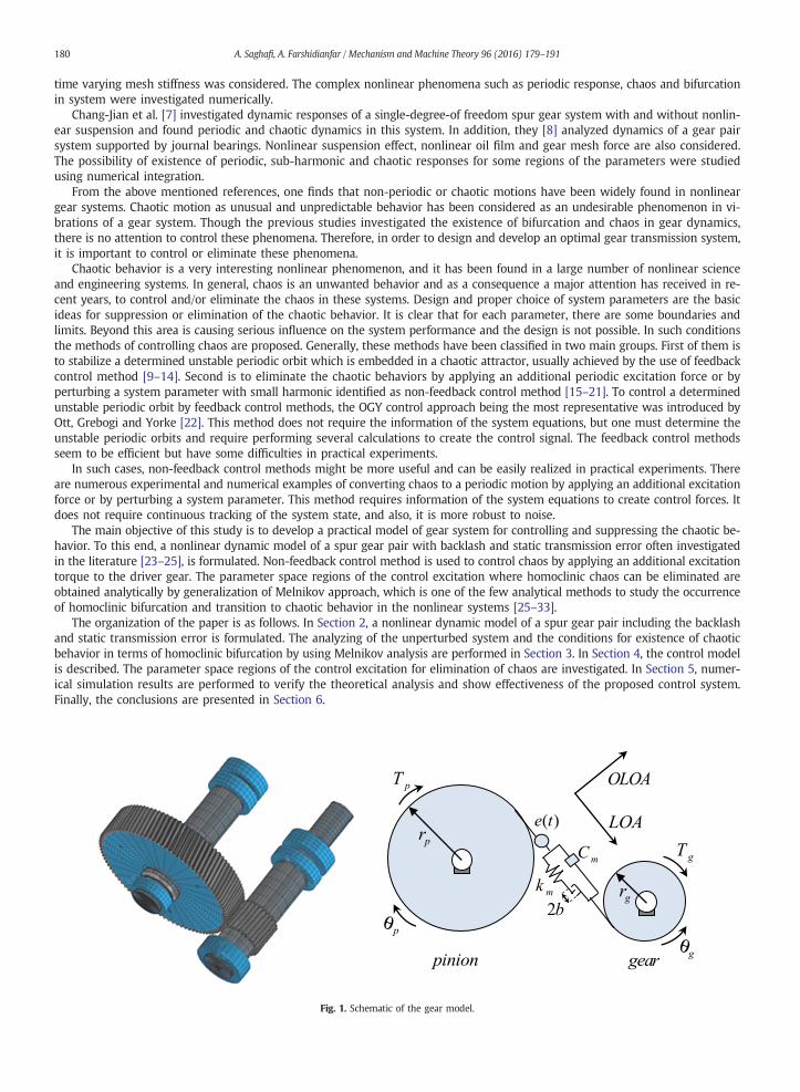
In this paper, a nonlinear dynamic model of a gear pair system supported by rigid mounts including the backlash and statictransmission error is investigated. In this model, the gear mesh is represented as a pair of rigid disk connected by a spring damperset along the line of action, as shown in Fig. 1. The backlash function fh, is usually used to represent gear clearances, and thedisplacement function e(t), is also applied at the gear mesh interface to represent static transmission error. Considering θp andθg as the torsional displacements of pinion and gear, the equations of torsional motion of the 2-degree of-freedom model aregiven as
Ipd2θpdt2
þ rpcm rpdθpdt
−rgdθgdt
−de tð Þdt
� �þ rpkm f h rpθp−rgθg−e tð Þ
� �¼ Tp ð1� aÞ
Igd2θgdt2
−rgcm rpdθpdt
−rgdθgdt
−de tð Þdt
� �−rgkm f h rpθp−rgθg−e tð Þ
� �¼ −Tg : ð1� bÞ
In these equations, rp and rg, are the base circle radius of the pinion and the gear. Ip and Ig are the mass moment of inertia ofthe gears. km and cm represent the gear mesh stiffness and damping coefficients. Additionally, external torques Tp and Tg act on thepinion and the gear, respectively. Eqs. (1-a) and (1-b) can be reduced into Eq. (2) by defining a new variable ~x ¼ rpθp−rgθg−eðtÞ,which is the difference between the dynamic and static transmission error.
md2~xdt2
þ cmd~xdt
þ km f h ~xð Þ ¼ F̂m þ F̂e tð Þ ð2Þ
Where
m ¼ IpIgIgr
2p þ Ipr
2g; F̂m ¼ m
TprpIp
þ TgrgIg
!; F̂e tð Þ ¼ −m
d2e tð Þdt2
:
Here, m is the equivalent mass representing the total inertia of the gear pair, F̂m is the average force transmitted through thegear pair, and the internal excitation term F̂eðtÞ arises from the static transmission error. The gear pair has a clearance equal to 2balong the line of action, which may be designed for better lubrication and reduction of interference, or caused by wear andmounting errors. The backlash function fh, is a nonlinear displacement function and can be expressed as
f h ~xð Þ ¼~x− 1−αð Þb b b ~xα~x −b ≤ ~x ≤ b~xþ 1−αð Þb b b−~x
8<: : ð3Þ
The static transmission error due to any manufacturing errors and teeth deformations from perfect involute form is one of themost important sources of vibration and noise in gear systems which also affect all gearbox elements. Since the mean angularvelocities of the gears are constant, the static transmission error can be approximated as a periodic function, its fundamental fre-quency is the meshing frequency [23]. So, the static transmission error is considered as harmonic with e(t) = e(t + 2π/ωe) =e cos(ωet + ϕe). A non-dimensional form of the above equation can be obtained by defining
x ¼ ~x=b; ωn ¼ffiffiffiffiffiffiffiffiffiffiffiffiffikm=m
q; τ ¼ ωnt; Ωe ¼ ωe=ωn ;
~μ ¼ c=2mωn;~Fm ¼ F̂m=bkm; ~Fe ¼ e=b :
So, the dimensionless equation of the gear pair can be written as
d2xdτ2
þ 2~μdxdτ
þ f h xð Þ ¼ ~Fm þ ~FeΩ2e cos Ωeτ þ ϕeð Þ ð4Þ
where
f h xð Þ ¼x− 1−αð Þ 1 b xαx −1≤ x ≤ 1xþ 1−αð Þ 1 b−x
8<: :
182 A. Saghafi, A. Farshidianfar / Mechanism and Machine Theory 96 (2016) 179–191
fh is a stepwise linear function and a 3-order approximation polynomial is recommended to express this function. For α = 0,the approximated function can be expressed as: fh(x) = −0.1667x + 0.1667x3. Substituting fh into Eq. (4), the equation of motioncan be obtained as
d2xdτ2
þ 2~μdxdτ
þ −0:1667xþ 0:1667x3� �
¼ ~Fm þ ~FeΩ2e cos Ωeτ þ ϕeð Þ : ð5Þ
Eq. (5) presents a generalized dynamic model of a spur gear pair system. The proposed study is focused on the prediction andcontrol of the homoclinic bifurcation and chaos in this equation.
3. Global bifurcation and chaos prediction for gear model equation
Global homoclinic bifurcation is the occurrence of transverse intersection of the stable and unstable manifolds of thehomoclinic orbits and defined as a criterion for prediction of the chaotic behavior. The Melnikov analysis is one of the few ana-lytical methods to study the global bifurcation of the system and provides the estimate in the parameter space for existence of thechaos in nonlinear systems [28–33]. In this section, the conditions for existence of the chaotic behavior in terms of homoclinicbifurcation are performed by using Melnikov analysis. In order to apply this technique and carry out this study, the homoclinicorbits, stable and unstable manifolds of the unperturbed system are derived. The damping term, the average force, and also theexcitation term are considered as small perturbations to the Hamiltonian system. Thus, considering ε as a small parameter andscaling ~μ ¼ εμ , ~Fm ¼ ε f m, and ~Fe ¼ ε f e, the perturbed Eq. (5) can be rewritten as
x� ¼ yy� ¼ −2εμ x
� þ 0:1667x−0:1667x3� �
þ εð f m þ f eΩ2e cos Ωeτ þ ϕeð Þ :
ð6Þ
For the unperturbed system, when ε = 0, the differential Eq. (6) is simplified to
x� ¼ yy� ¼ 0:1667x−0:1667x3� �
¼ ax−cx3� �
:ð7Þ
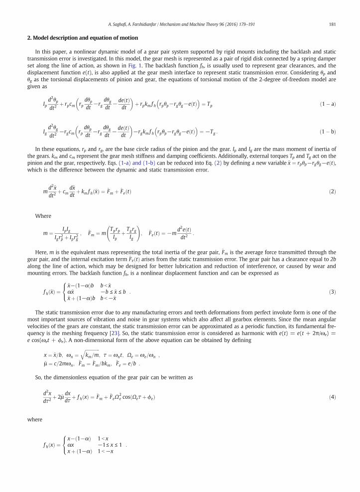
The unperturbed system Eq. (7) is a planar Hamiltonian system with a Hamiltonian function as H(x, y) = 0.5y2 −0.5ax2 + 0.25cx4. The unperturbed system has three fixed points. From the linear stability analysis, ðþ ffiffiffiffiffiffiffiffi
a=cp
;0Þ and ð− ffiffiffiffiffiffiffiffia=c
p;0Þ
are centers, and (0, 0) is a saddle point. The saddle point is connected to itself by two homoclinic orbits, and can be obtainedas
xh τð Þ; yh τð Þð Þ ¼ �ffiffiffiffiffiffi2ac
rsech
ffiffiffia
pτð Þ� �
; ∓
ffiffiffi2c
ra � sech
ffiffiffia
pτð Þ� �
tanhffiffiffia
pτð Þ� � !
ð8Þ
where τ−τ0 ¼ τ. Stable and unstable manifolds of the homoclinic orbits for the unperturbed system are shown in Fig. 2.
-1.5 -1 -0.5 0 0.5 1 1.5-0.4
-0.3
-0.2
-0.1
0
0.1
0.2
0.3
0.4
x
y
uWsW
uW s
+
+W
Fig. 2. Stable and unstable manifolds of the homoclinic orbits.
183A. Saghafi, A. Farshidianfar / Mechanism and Machine Theory 96 (2016) 179–191
When the perturbation terms are added to the unperturbed system, the closed homoclinic orbits break, and may intersectmanifolds. The Melnikov method measures the distance between the stable and unstable manifolds of the perturbed system inthe Poincare section, and provides the estimate for transverse intersection of the stable and unstable manifolds of the homoclinicorbits, and hence the occurrence of homoclinic bifurcation and transition to chaotic behavior. According to this theory, theconditions for transverse intersection of the stable and unstable manifolds are given by M(τ0) = 0 and dM(τ0)/dτ0 ≠ 0, whereM(τ0) is the Melnikov function and defined as follows [26,27]
Mð
⇒
M τ0ð Þ ¼Zþ∞
−∞
p Xh τ−τ0ð Þð Þ ∧ qðXh τ−τ0ð Þ; τÞdτ ¼Zþ∞
−∞
p Xh τð Þð Þ ∧ qðXh τð Þ; τ þ τ0Þdτ : ð9Þ
In this equation, Xh = (xh, yh) is homoclinic orbit. p and q represent the vector field and the perturbed vector of Eq. (6) givenby
p x; yð Þ ¼ y; ax−cx3� �
q x; y; τð Þ ¼ ð0;−2μ x� þ f m þ Ω2
e f e cos Ωeτ þ ϕeð Þ :ð10Þ
Using Eqs. (8) and (10) to carry out integration of Eq. (9), the Melnikov integral can be rewritten as
τ0Þ ¼Zþ∞
−∞
yhð−2μyh þ f m þΩ2e f e cos Ωe τ þ τ0ð Þ þ ϕeð ÞÞdτ
M τ0ð Þ ¼Zþ∞
−∞
∓
ffiffiffi2c
ra� sech
ffiffiffia
pτ
� �tanh
ffiffiffia
pτ
� � !−2μ
�∓
ffiffiffi2c
ra� sech
ffiffiffia
pτ
� �tanh
ffiffiffia
pτ
� ��þ f m þ f eΩ2e cos Ωe τ þ τ0ð Þ þ ϕeð Þ
!dτ
ð11Þ
After evaluation of the above integral, the Melnikov function is given by
M� τ0ð Þ ¼ −83μ að Þ2cffiffiffia
p �ffiffiffi2c
rf eΩ
3eπ � sech
πΩe
2ffiffiffia
p� �
sin Ωeτ0 þ ϕeð Þ : ð12Þ
Using this equation, the condition for transverse intersection of the stable and unstable manifolds is obtained as
−83μ að Þ2cffiffiffia
p
bffiffiffi2c
rf eΩ
3eπ � sech
πΩe
2ffiffiffia
p� �
:
ð13Þ
From this relation, the threshold values for the occurrence of homoclinic bifurcation and transition to chaotic behavior areobtained.
4. Controller design based on chaos control concept
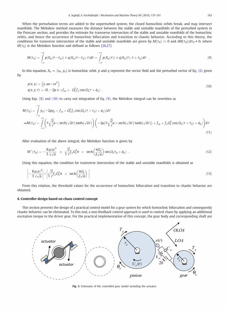
This section presents the design of a practical control model for a gear system for which homoclinic bifurcation and consequentlychaotic behavior can be eliminated. To this end, a non-feedback control approach is used to control chaos by applying an additionalexcitation torque to the driver gear. For the practical implementation of this concept, the gear body and corresponding shaft are
Fig. 3. Schematic of the controlled gear model including the actuator.
184 A. Saghafi, A. Farshidianfar / Mechanism and Machine Theory 96 (2016) 179–191
connected via several actuators for one set of gear–shaft coupling, as shown in Fig. 3. These actuators can transmit themean torque andsimultaneously generate additional excitation torque. The suitable parameter spaces for the additional excitation, where homoclinicchaos can be eliminated, are obtained analytically by generalization of Melnikov approach. The dynamic equations of this systemincluding the actuator can be rewritten as
Ipd2θpdt2
þ rpcm rpdθpdt
−rgdθgdt
−dedt
� �þ rpkm f h rpθp−rgθg−e tð Þ
� �¼ Tp þ Up tð Þ ð14� aÞ
Igd2θgdt2
−rgcm rpdθpdt
−rgdθgdt
−dedt
� �−rgkm f h rpθp−rgθg−e tð Þ
� �¼ −Tg : ð14� bÞ
The additional external excitation Up(t) is the chaos elimination excitation and is considered as harmonic with Up(t) =Up cos(ωpt + ϕp). Where Up, ωp, and ϕp are the amplitude, frequency, and phase of the excitation term, respectively. Similarto Eq. (1-a to 1-b), the vibration Eq. (14-a to 14-b) can be simplified as
md2~xdt2
þ cmd~xdt
þ km f h ~xð Þ ¼ F̂m þ F̂e tð Þ þ F̂p cos ωpt þ ϕp
� �: ð15Þ
Where F̂p ¼ mrpUp=Ip. Further, by defining the dimensionless excitation frequency and amplitude as Ωp ¼ ωp=ωn; ~Fp ¼F̂p=bkm and also considering the dimensionless parameters defined in Eq. (4), the following equation is obtained
d2xdτ2
þ 2~μdxdτ
þ f h xð Þ ¼ ~Fm þ ~FeΩ2e cos Ωeτ þ ϕeð Þ þ ~Fp cos Ωpτ þ ϕp
� �: ð16Þ
The amplitude of excitation term is considered as weak perturbations as ~Fp ¼ ε f p. Similar to Eq. (6), the Melnikov function isobtained as
M τ0ð Þ ¼Zþ∞
−∞
yhð−2μyh þ f m þΩ2e f e cos Ωe τ þ τ0ð Þ þ ϕeð Þ þ f p cosðΩp τ þ τ0ð Þ þ ϕpÞÞdτ
⇒M τ0ð Þ ¼Zþ∞
−∞
∓
ffiffiffi2c
ra� sech
ffiffiffia
pτ
� �tanh
ffiffiffia
pτ
� � !ð−2μ ∓
ffiffiffi2c
ra� sech
ffiffiffia
pτ
� �tanh
ffiffiffia
pτ
� � !…
…þ f m þ f eΩ2e cos Ωe τ þ τ0ð Þ þ ϕeð Þ þ f p cosðΩp τ þ τ0ð Þ þ ϕpÞÞdτ
ð17Þ
After evaluating the above integral, the Melnikov function can be presented as
M� τ0ð Þ ¼ A� B sin Ωeτ0 þ ϕeð Þ � C sin Ωpτ0 þ ϕp
� �ð18Þ
with
A ¼ −83μ að Þ2cffiffiffia
p ; B ¼ffiffiffi2c
rf eΩ
3eπ � sech
πΩe
2ffiffiffia
p� �
; C ¼ffiffiffi2c
rf pΩpπ � sech
πΩp
2ffiffiffia
p� �
:
ffiffiq
Compared with Eq. (12), the control excitation term� 2c f pΩpπ � sechðπΩp
2ffiffia
p Þ sinðΩpτ0 þ ϕpÞ appears in the Melnikov function.In the following, this function will be used to establish the chaos elimination results. The objective is to choose the control param-eter values of fp, Ωp, and ϕp such that the chaotic behavior in primary system be eliminated.
As mentioned in the previous section, in the absence of chaos elimination excitation, Eq. (13) provides a condition for trans-verse intersection of the stable and unstable manifolds, and hence occurrence of chaotic behavior. Now, the additional excitationis added on the system, such that the Melnikov function always has the same sign. In the present case, a necessary condition forM±(τ0) to be the same sign for all τ0 is obtained as [15]
Cj j N Bj j− Aj j ¼ Cminffiffiffi2c
rf pΩpπ � sech
πΩp
2ffiffiffia
p� �
Nffiffiffi2c
rf eΩ
3eπ � sech
πΩe
2ffiffiffia
p� �
− −83μ að Þ2cffiffiffia
p
:ð19Þ
185A. Saghafi, A. Farshidianfar / Mechanism and Machine Theory 96 (2016) 179–191
The optimal excitation phase (ϕp = ϕoptimum), which corresponds to the widest amplitude range for the chaos elimination, isobtained for the situation in which the maximum (maximum for A b 0 and minimum for A N 0) of A ± B sin(Ωeτ0 + ϕe) and∓ Cmin sin(Ωpτ0 + ϕoptimum) occur at the same τ0. In the following, B and C will be considered to be the same sign and also asa positive term. It is clear that changing this sign is equivalent to shift the phase as ϕe → ~ϕe þ π . In this case, for Ωp =mΩe, (m = 1, 2, 3, …), two different sets of the optimal values of excitation phase are obtained as
(a
f or Mþ andA b 0� �
or M− andA N 0ð Þ⇒ ϕoptimum ¼
π þ ϕeð Þ f or m ¼ 4n−3ð Þπ.
2þ ϕe
� �f or m ¼ 4n−2ð Þ
0þ ϕeð Þ f or m ¼ 4n−1ð Þ3π.
2þ ϕe
� �f or m ¼ 4nð Þ
8>>>><>>>>:
f or Mþ andA N 0� �
or M− andA b 0ð Þ⇒ ϕoptimum ¼
π þ ϕeð Þ f or m ¼ 4n−3ð Þπ.
2þ ϕe
� �f or m ¼ 4nð Þ
0þ ϕeð Þ f or m ¼ 4n−1ð Þ3π.
2þ ϕe
� �f or m ¼ 4n−2ð Þ :
8>>>><>>>>:
ð20Þ
Moreover, for the optimal excitation phase the upper threshold value of excitation amplitude can be easily obtained, for whichM±(τ0) have the same sign for all τ0. Also, the Melnikov function indicated that the excitation phase can be changed in allowedinterval as [ϕoptimum − Δϕmax , ϕoptimum + Δϕmax], such that the Melnikov function always have the same sign. Δϕmax, is the max-imum deviation of excitation phase from optimal phase. It is clear that the maximum deviation of excitation phase is obtainedbased on the nearest zeros of A ± B sin(Ωeτ0 + ϕe) and ± C sin(Ωpτ0 + ϕoptimum) given by
Δϕmax ¼ Ωp τ20−τ10� �
¼ m arcsinAB−ϕe
� �−kπþ ϕoptimum : ð21Þ
The value of τ01 and τ02 is the nearest zeros of ± C sin(Ωpτ0 + ϕoptimum) and A ± B sin(Ωeτ0 + ϕe), respectively. For an arbitrarydeviation of excitation phase from ϕoptimum (0 b Δϕ b Δϕmax), one can easily obtain the allowed amplitude value of Cmax(bCmax atϕoptimum), and Cmin(NCmin at ϕoptimum). Therefore, there exist certain suitable excitation phase and amplitude intervals for control-ling the chaotic behavior in a gear system.
5. Simulation results and discussion
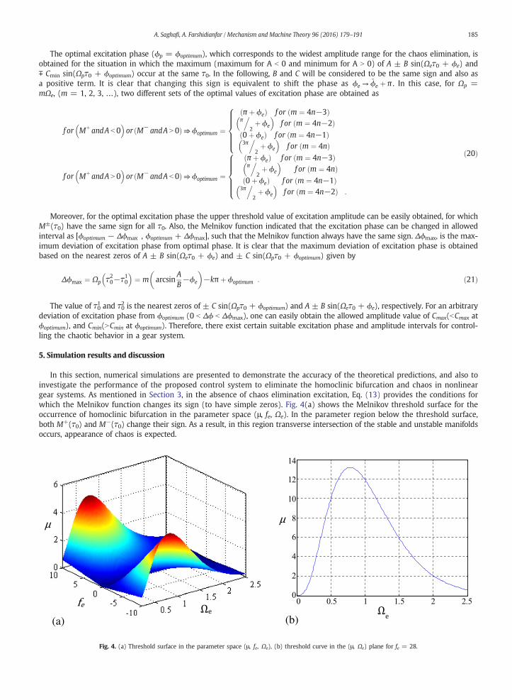
In this section, numerical simulations are presented to demonstrate the accuracy of the theoretical predictions, and also toinvestigate the performance of the proposed control system to eliminate the homoclinic bifurcation and chaos in nonlineargear systems. As mentioned in Section 3, in the absence of chaos elimination excitation, Eq. (13) provides the conditions forwhich the Melnikov function changes its sign (to have simple zeros). Fig. 4(a) shows the Melnikov threshold surface for theoccurrence of homoclinic bifurcation in the parameter space (μ, fe, Ωe). In the parameter region below the threshold surface,both M+(τ0) and M−(τ0) change their sign. As a result, in this region transverse intersection of the stable and unstable manifoldsoccurs, appearance of chaos is expected.
) (b)
Fig. 4. (a) Threshold surface in the parameter space (μ, fe, Ωe), (b) threshold curve in the (μ, Ωe) plane for fe = 28.

0.05 0.1 0.15 0.2 0.25
-0.1
-0.08
-0.06
-0.04
-0.02
0
0.02
0.04
Max
imum
Lya
puno
v ex
pone
nt
x
(a) (b)
Fig. 5. (a) Bifurcation diagram, and (b) corresponding maximum Lyapunov exponent for ~μ (~μ ¼ εμ) as the control parameter.
186 A. Saghafi, A. Farshidianfar / Mechanism and Machine Theory 96 (2016) 179–191
According to Eq. (13) and by choosing μ as the control parameter, the condition for transverse intersection of the stable andunstable manifolds is obtained as
μ b34a
ffiffiffiffiffiffic2a
rf ej jπΩ3
e � sechπΩe
2ffiffiffia
p� �
; f or μ N 0ð Þ : ð22Þ
The critical values of μ versus frequency Ωe, at fe = 28 are plotted in Fig. 4(b). In the region below the threshold curve thesystem has transverse homoclinic orbits and resulting occurrence of the chaotic behavior.
-1.5 -1 -0.5 0 0.5 1 1.5
-0.2
-0.1
0
0.1
0.2
0.3
0.4
0.5
x Ω
y
0 0.5 1 1.5 20
5
10
15x 10
4
FFT
(a)
(b) (c)
0 200 400 600 800 1000 1200 1400 1600 1800
-1
0
1
x
Fig. 6. (a) Time history, (b) Poincare section, and (c) Fourier spectra for μ = 8.
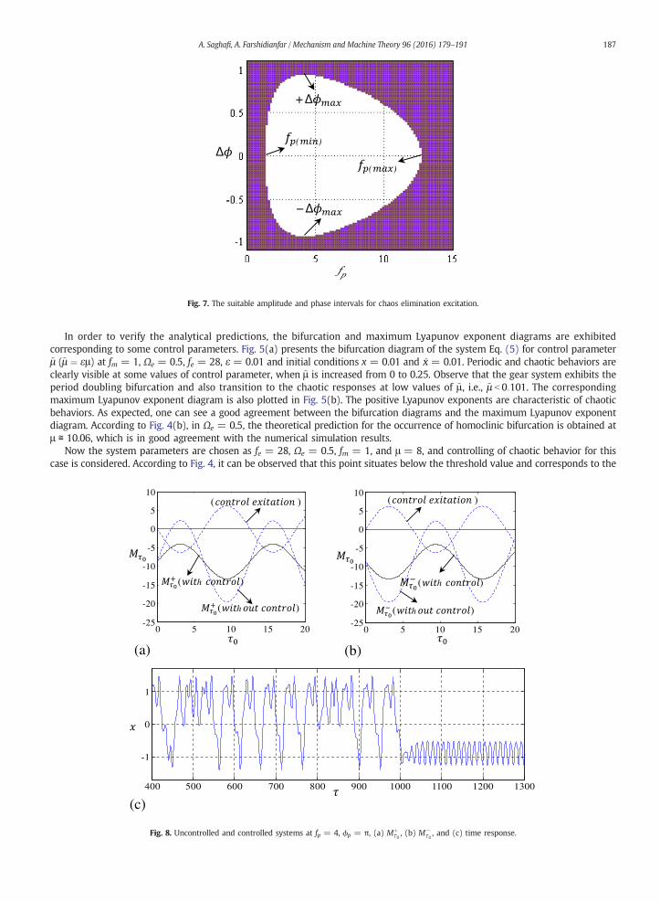
Fig. 7. The suitable amplitude and phase intervals for chaos elimination excitation.
187A. Saghafi, A. Farshidianfar / Mechanism and Machine Theory 96 (2016) 179–191
In order to verify the analytical predictions, the bifurcation and maximum Lyapunov exponent diagrams are exhibitedcorresponding to some control parameters. Fig. 5(a) presents the bifurcation diagram of the system Eq. (5) for control parameter~μ (~μ ¼ εμ) at fm = 1, Ωe = 0.5, fe = 28, ε = 0.01 and initial conditions x = 0.01 and ẋ = 0.01. Periodic and chaotic behaviors areclearly visible at some values of control parameter, when ~μ is increased from 0 to 0.25. Observe that the gear system exhibits theperiod doubling bifurcation and also transition to the chaotic responses at low values of ~μ , i.e., ~μ b 0:101. The correspondingmaximum Lyapunov exponent diagram is also plotted in Fig. 5(b). The positive Lyapunov exponents are characteristic of chaoticbehaviors. As expected, one can see a good agreement between the bifurcation diagrams and the maximum Lyapunov exponentdiagram. According to Fig. 4(b), in Ωe = 0.5, the theoretical prediction for the occurrence of homoclinic bifurcation is obtained atμ ≅ 10.06, which is in good agreement with the numerical simulation results.
Now the system parameters are chosen as fe = 28, Ωe = 0.5, fm = 1, and μ = 8, and controlling of chaotic behavior for thiscase is considered. According to Fig. 4, it can be observed that this point situates below the threshold value and corresponds to the
0 5 10 15 20-25
-20
-15
-10
-5
0
5
10
( )
( )
( )
0 5 10 15 20-25
-20
-15
-10
-5
0
5
10
( )
( )
( )
(a) (b)
400 500 600 700 800 900 1000 1100 1200 1300
-1
0
1
(c)
Fig. 8. Uncontrolled and controlled systems at fp = 4, ϕp = π, (a) Mþτ0 , (b) M−
τ0 , and (c) time response.
0 5 10 15 20
-20
-10
0
10
20
( )
( )
( )
0 5 10 15 20
-20
-10
0
10
20
( )
( )
( )
(a) (b)
400 500 600 700 800 900 1000 1100 1200 1300
-1
0
1
(c)
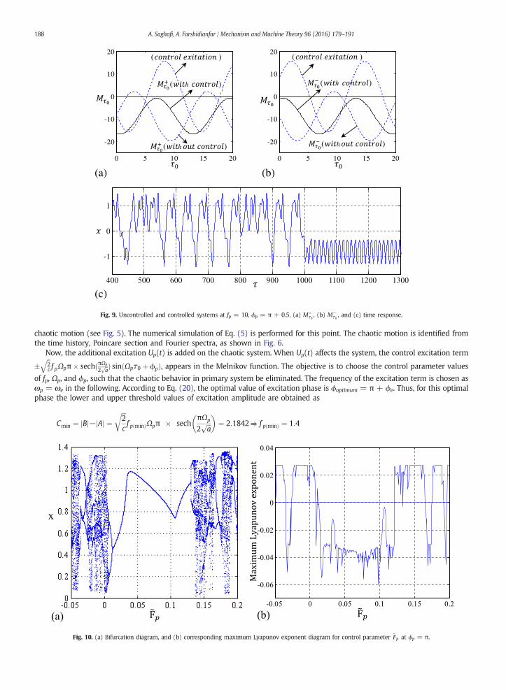
Fig. 9. Uncontrolled and controlled systems at fp = 10, ϕp = π + 0.5, (a) Mþτ0 , (b) M−
τ0 , and (c) time response.
188 A. Saghafi, A. Farshidianfar / Mechanism and Machine Theory 96 (2016) 179–191
chaotic motion (see Fig. 5). The numerical simulation of Eq. (5) is performed for this point. The chaotic motion is identified fromthe time history, Poincare section and Fourier spectra, as shown in Fig. 6.
Now, the additional excitation Up(t) is added on the chaotic system. When Up(t) affects the system, the control excitation term
�ffiffi2c
qf pΩpπ� sechðπΩp
2ffiffia
p Þ sinðΩpτ0 þ ϕpÞ, appears in the Melnikov function. The objective is to choose the control parameter values
of fp, Ωp, and ϕp, such that the chaotic behavior in primary system be eliminated. The frequency of the excitation term is chosen asωp = ωe in the following. According to Eq. (20), the optimal value of excitation phase is ϕoptimum = π + ϕe. Thus, for this optimalphase the lower and upper threshold values of excitation amplitude are obtained as
Cmin ¼ Bj j− Aj j ¼ffiffiffi2c
rf p minð ÞΩpπ � sech
πΩp
2ffiffiffia
p� �
¼ 2:1842⇒ f p minð Þ ¼ 1:4
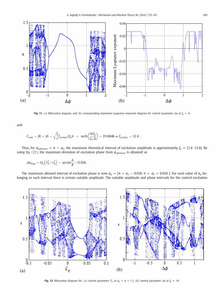
Fig. 10. (a) Bifurcation diagram, and (b) corresponding maximum Lyapunov exponent diagram for control parameter ~Fp at ϕp = π.
x
(a)-2 -1 0 1 2
-0.06
-0.04
-0.02
0
0.02
0.04
Max
imum
Lya
puno
v ex
pone
nt
(b)
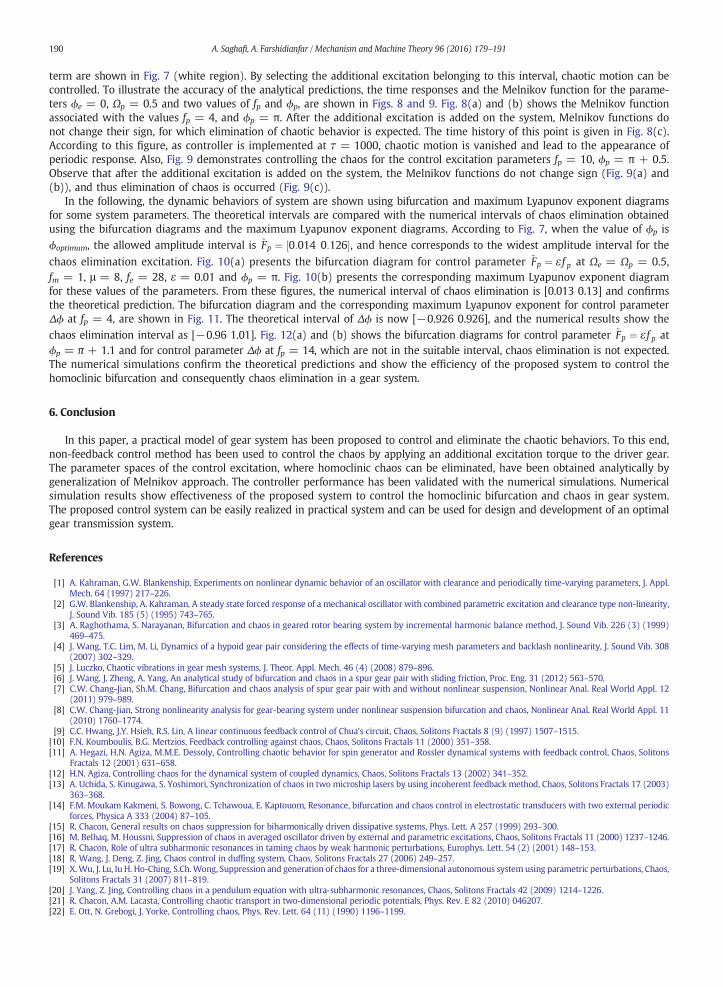
Fig. 11. (a) Bifurcation diagram, and (b) corresponding maximum Lyapunov exponent diagram for control parameter Δϕ at fp = 4.
189A. Saghafi, A. Farshidianfar / Mechanism and Machine Theory 96 (2016) 179–191
and
x
(a)
Cmax ¼ Bj j þ Aj j ¼ffiffiffi2c
rf p maxð ÞΩpπ � sech
πΩp
2ffiffiffia
p� �
¼ 19:6046⇒ f p maxð Þ ¼ 12:6 :
Thus, for ϕoptimum = π + ϕe, the maximum theoretical interval of excitation amplitude is approximately fp = [1.4 12.6]. Byusing Eq. (21), the maximum deviation of excitation phase from ϕoptimum is obtained as
Δϕmax ¼ Ωp τ20−τ10� �
¼ arcsinAB¼ 0:926 :
The maximum allowed interval of excitation phase is now ϕp = [π + ϕe − 0.926 π + ϕe + 0.926 ]. For each value of ϕp be-longing to such interval there is certain suitable amplitude. The suitable amplitude and phase intervals for the control excitation
F Δ(b)
x
Fig. 12. Bifurcation diagram for: (a) control parameter ~Fp at ϕp = π + 1.1, (b) control parameter Δϕ at fp = 14.
190 A. Saghafi, A. Farshidianfar / Mechanism and Machine Theory 96 (2016) 179–191
term are shown in Fig. 7 (white region). By selecting the additional excitation belonging to this interval, chaotic motion can becontrolled. To illustrate the accuracy of the analytical predictions, the time responses and the Melnikov function for the parame-ters ϕe = 0, Ωp = 0.5 and two values of fp and ϕp, are shown in Figs. 8 and 9. Fig. 8(a) and (b) shows the Melnikov functionassociated with the values fp = 4, and ϕp = π. After the additional excitation is added on the system, Melnikov functions donot change their sign, for which elimination of chaotic behavior is expected. The time history of this point is given in Fig. 8(c).According to this figure, as controller is implemented at τ = 1000, chaotic motion is vanished and lead to the appearance ofperiodic response. Also, Fig. 9 demonstrates controlling the chaos for the control excitation parameters fp = 10, ϕp = π + 0.5.Observe that after the additional excitation is added on the system, the Melnikov functions do not change sign (Fig. 9(a) and(b)), and thus elimination of chaos is occurred (Fig. 9(c)).
In the following, the dynamic behaviors of system are shown using bifurcation and maximum Lyapunov exponent diagramsfor some system parameters. The theoretical intervals are compared with the numerical intervals of chaos elimination obtainedusing the bifurcation diagrams and the maximum Lyapunov exponent diagrams. According to Fig. 7, when the value of ϕp isϕoptimum, the allowed amplitude interval is ~Fp ¼ ½0:014 0:126�, and hence corresponds to the widest amplitude interval for the
chaos elimination excitation. Fig. 10(a) presents the bifurcation diagram for control parameter ~Fp ¼ ε f p at Ωe = Ωp = 0.5,fm = 1, μ = 8, fe = 28, ε = 0.01 and ϕp = π. Fig. 10(b) presents the corresponding maximum Lyapunov exponent diagramfor these values of the parameters. From these figures, the numerical interval of chaos elimination is [0.013 0.13] and confirmsthe theoretical prediction. The bifurcation diagram and the corresponding maximum Lyapunov exponent for control parameterΔϕ at fp = 4, are shown in Fig. 11. The theoretical interval of Δϕ is now [−0.926 0.926], and the numerical results show thechaos elimination interval as [−0.96 1.01]. Fig. 12(a) and (b) shows the bifurcation diagrams for control parameter ~Fp ¼ ε f p atϕp = π + 1.1 and for control parameter Δϕ at fp = 14, which are not in the suitable interval, chaos elimination is not expected.The numerical simulations confirm the theoretical predictions and show the efficiency of the proposed system to control thehomoclinic bifurcation and consequently chaos elimination in a gear system.
6. Conclusion
In this paper, a practical model of gear system has been proposed to control and eliminate the chaotic behaviors. To this end,non-feedback control method has been used to control the chaos by applying an additional excitation torque to the driver gear.The parameter spaces of the control excitation, where homoclinic chaos can be eliminated, have been obtained analytically bygeneralization of Melnikov approach. The controller performance has been validated with the numerical simulations. Numericalsimulation results show effectiveness of the proposed system to control the homoclinic bifurcation and chaos in gear system.The proposed control system can be easily realized in practical system and can be used for design and development of an optimalgear transmission system.
References
[1] A. Kahraman, G.W. Blankenship, Experiments on nonlinear dynamic behavior of an oscillator with clearance and periodically time-varying parameters, J. Appl.Mech. 64 (1997) 217–226.
[2] G.W. Blankenship, A. Kahraman, A steady state forced response of a mechanical oscillator with combined parametric excitation and clearance type non-linearity,J. Sound Vib. 185 (5) (1995) 743–765.
[3] A. Raghothama, S. Narayanan, Bifurcation and chaos in geared rotor bearing system by incremental harmonic balance method, J. Sound Vib. 226 (3) (1999)469–475.
[4] J. Wang, T.C. Lim, M. Li, Dynamics of a hypoid gear pair considering the effects of time-varying mesh parameters and backlash nonlinearity, J. Sound Vib. 308(2007) 302–329.
[5] J. Luczko, Chaotic vibrations in gear mesh systems, J. Theor. Appl. Mech. 46 (4) (2008) 879–896.[6] J. Wang, J. Zheng, A. Yang, An analytical study of bifurcation and chaos in a spur gear pair with sliding friction, Proc. Eng. 31 (2012) 563–570.[7] C.W. Chang-Jian, Sh.M. Chang, Bifurcation and chaos analysis of spur gear pair with and without nonlinear suspension, Nonlinear Anal. Real World Appl. 12
(2011) 979–989.[8] C.W. Chang-Jian, Strong nonlinearity analysis for gear-bearing system under nonlinear suspension bifurcation and chaos, Nonlinear Anal. Real World Appl. 11
(2010) 1760–1774.[9] C.C. Hwang, J.Y. Hsieh, R.S. Lin, A linear continuous feedback control of Chua's circuit, Chaos, Solitons Fractals 8 (9) (1997) 1507–1515.
[10] F.N. Koumboulis, B.G. Mertzios, Feedback controlling against chaos, Chaos, Solitons Fractals 11 (2000) 351–358.[11] A. Hegazi, H.N. Agiza, M.M.E. Dessoly, Controlling chaotic behavior for spin generator and Rossler dynamical systems with feedback control, Chaos, Solitons
Fractals 12 (2001) 631–658.[12] H.N. Agiza, Controlling chaos for the dynamical system of coupled dynamics, Chaos, Solitons Fractals 13 (2002) 341–352.[13] A. Uchida, S. Kinugawa, S. Yoshimori, Synchronization of chaos in two microship lasers by using incoherent feedback method, Chaos, Solitons Fractals 17 (2003)
363–368.[14] F.M. Moukam Kakmeni, S. Bowong, C. Tchawoua, E. Kaptouom, Resonance, bifurcation and chaos control in electrostatic transducers with two external periodic
forces, Physica A 333 (2004) 87–105.[15] R. Chacon, General results on chaos suppression for biharmonically driven dissipative systems, Phys. Lett. A 257 (1999) 293–300.[16] M. Belhaq, M. Houssni, Suppression of chaos in averaged oscillator driven by external and parametric excitations, Chaos, Solitons Fractals 11 (2000) 1237–1246.[17] R. Chacon, Role of ultra subharmonic resonances in taming chaos by weak harmonic perturbations, Europhys. Lett. 54 (2) (2001) 148–153.[18] R. Wang, J. Deng, Z. Jing, Chaos control in duffing system, Chaos, Solitons Fractals 27 (2006) 249–257.[19] X.Wu, J. Lu, Iu H. Ho-Ching, S.Ch.Wong, Suppression and generation of chaos for a three-dimensional autonomous systemusing parametric perturbations, Chaos,
Solitons Fractals 31 (2007) 811–819.[20] J. Yang, Z. Jing, Controlling chaos in a pendulum equation with ultra-subharmonic resonances, Chaos, Solitons Fractals 42 (2009) 1214–1226.[21] R. Chacon, A.M. Lacasta, Controlling chaotic transport in two-dimensional periodic potentials, Phys. Rev. E 82 (2010) 046207.[22] E. Ott, N. Grebogi, J. Yorke, Controlling chaos, Phys. Rev. Lett. 64 (11) (1990) 1196–1199.

191A. Saghafi, A. Farshidianfar / Mechanism and Machine Theory 96 (2016) 179–191
[23] Y. Shen, S. Yang, X. Liu, Nonlinear dynamics of a spur gear pair with time-varying stiffness and backlash based on incremental harmonic balance method, Int. J.Mech. Sci. 48 (2006) 1256–1263.
[24] G. Bonori, F. Pellicano, Non-smooth dynamics of spur gears with manufacturing errors, J. Sound Vib. 306 (2007) 271–283.[25] A. Farshidianfar, A. Saghafi, Global bifurcation and chaos analysis in nonlinear vibration of spur gear systems, Nonlinear Dyn. 75 (2014) 783–806.[26] S. Wiggins, Global Bifurcations and Chaos, Springer, New York, 1988.[27] S. Wiggins, Introduction to Applied Nonlinear Dynamical Systems and Chaos, Springer, NewYork, 1990.[28] M. SieweSiewe, F.M. MoukamKakmeni, C. Tchawoua, P. Woafo, Bifurcations and chaos in the triple-well φ6 Van der Pol oscillator driven by external and
parametric excitations, Physica A 357 (2005) 383–396.[29] J. Awrejcewicz, Y. Pyryev, Chaos prediction in the duffing-type system with friction using Melnikov's function, Nonlinear Anal. RealWorld Appl. 7 (2006) 12–24.[30] K. Yagasaki, Bifurcations and chaos in vibrating micro cantilevers of tapping mode atomic force microscopy, Int. J. Non-Linear Mech. 42 (2007) 658–672.[31] M. SieweSiewe, H. Cao, M. Sanjuan, On the occurrence of chaos in a parametrically driven extended Rayleigh oscillator with three-well potential, Chaos, Solitons
Fractals 41 (2009) 772–782.[32] G. Litak, M. Borowiec, A. Syta, K. Szabelski, Transition to chaos in the self-excited systemwith a cubic doublewell potential and parametric forcing, Chaos, Solitons
Fractals 40 (2009) 2414–2429.[33] L. Zhou, Y. Chen, F. Chen, Global bifurcation analysis and chaos of an arch structure with parametric and forced excitation, Mech. Res. Commun. 37 (1) (2010)
67–71.


![Bifurcation and Chaos of Gear Pair System Supported by ... · mesh stiffness, damping, gear errors profile modification and backlash. Cai and Hayashi [9] calculated the opti- mum](https://img.dokumen.tips/doc/110x75/5ec58b34a482d05ea361c337/bifurcation-and-chaos-of-gear-pair-system-supported-by-mesh-stiffness-damping.jpg)