Embed Size (px)
DESCRIPTION
Vacuum Pumps
Citation preview

Mechanical vacuum pumps*
A.D. Chew BOC Edwards, Crawley, United Kingdom
Abstract This presentation gives an overview of the technology of contemporary primary and secondary mechanical vacuum pumps. For reference a brief history of vacuum and a summary of important and basic vacuum concepts are first presented.
1 Introduction Vacuum? It is just like turning on a tap. We have come to take for granted vacuum and its application, in all its degrees from vacuum forming, metallurgy, integrated circuitry fabrication to space simulation. The current provision, the engineering innovations, and global availability bear testament to the technical and commercial pioneers of the 19th and 20th centuries. The full history itself can be traced back to the ancient philosophers, however, here we touch briefly on the revolutionary work of the Natural Philosophers of the period of the Scientific Enlightenment.
There is some debate as to who achieved the first deliberate experimental vacuum (Berti or Torricelli), however, it is pretty certain that it was in Italy in the 1640s. The concept of a vacuum or void was a huge discussion amongst philosophical heavyweights across Europe in the 17th century. Indeed in reasoning against a vacuum (the Aristotolean ‘horror vacuii’), the Torricellian void in an inverted mercury column was said to have been filled with elements from the liquid mercury itself. As well as creating a vacuum, they also recognised the concept of outgasssing—a concept familiar to many practitioners today.
Galileo and Descartes were party to the debate be it via the concept of the weight of air (measured as 2.2 g/l compared to a ‘modern’ value of 1.3 g/l). The work spread from Italy (Baliani) to Mersenne and Pascal in France. It is worth noting that these intellectual endeavours were patronized by the great realms of the time both for application to live issues (for example, suction of water in mines) and also for the reflected glory on the patrons themselves. Science as Natural Philosophy was truly revered in the 17th century.
Von Guericke raised significant issues with the Torricellian void and combined the glass tube with his own suction pumps (reported by the Roman engineer Vitruvius) to produced the famous Magdeburg hemispheres. His problems with the correction of the (degassing) effects of the mercury column also paved the way for the ‘real’ gas correction to the ideal gas laws. Along the way his correction to the mercury column also led to its use for weather prediction (barometry) and in 1660 he predicted the onset of a heavy thunderstorm.
Pascal had by then joined the debate (as a fully fledged vacuist) as to what exactly could constitute a void. He led against the Aristotelean view, a victory which was to lead to the development of the gas laws.
*Disclaimer. The author and his employer, BOC Edwards, disclaim any and all liability and any warranty whatsoever relating to the practice, safety and results of the information, procedures or their applications described herein.
43

1.1 The gas laws
“If I have seen further it is by standing on the shoulders of giants” a famous quotation from a letter written by Isaac Newton in 1676. This may have been a way of giving credit to his correspondent, rival, and contemporary Robert Hooke, but I would like to think that the giants Newton had in mind would include Robert Boyle who was, amongst many other things, a great vacuum pioneer.
Boyle had a young Hooke as his assistant and circa 1660 they jointly developed an air pump, arguably the first vacuum-producing apparatus suitable for experiments. These included the investigation and extinguishing of the ringing of a bell. This is a common vacuum demonstration now in classrooms but was used by Boyle as evidence for his attack on the plenists (and for theological applications). This vacuum pump allowed the accurate investigation of the (inverse) relationship between pressure and volume: P1V1 = P2V2—Boyle’s (or Mariotte’s) Law.
At this time no temperature scale existed and he could not determine the relationship between ‘hotness’ and volume. Later work (1702) by Amontons developed the air thermometer—it relied on the increase in volume of a gas with temperature rather than the increase in volume of a liquid and gave us Amontons’ Law: P1T2 = P2T1.
Although Amontons had done the work before him, Charles is credited with the law V1T2 = V2T1 as measured on the Kelvin temperature scale. Gay-Lussac (also famed for his Law of Combined Volumes) in 1808 made definitive measurements and published results showing that every gas he tested obeyed this generalization. Dalton’s work on the law of the partial pressure of gases (1801) and Avogadro’s article (1811) stating that at the same temperature and pressure, equal volumes of different gases contain the same number of molecules would lead to the concept of the mole and Avogadro’s number. By 1860 our modern day view of the Ideal Gas Law was in existence and the Maxwell–Boltzmann theory further explained the gas laws in terms kinetics of individual molecules. This incorporated Bernoulli’s 1730s kinetic model of tiny gas molecules moving about in otherwise empty space (a foretelling of the van der Waals equation—perhaps the most commonly known of many Real Gas equations).
Boyle’s Law was the first of the gas laws and was a truly remarkable display of experimental procedure with the application of leading-edge contemporary technology. A vacuum pump was the catalyst and facilitating element as it would prove to be in many other major scientific milestones.
1.2 First industrial applications of vacuum
The development of vacuum technology made many contributions in the 17th to 19th centuries ranging from evidence to resolve to the philosophical confrontation between plenists and vacuuists, to the development of the gas laws. By the mid 19th century there seems to have been a major application of vacuum awaiting discovery. Step forward the humble light bulb.
Davy moved the world on from gas/oil/candle lighting in 1809 by creating an incandescent light arc-lamp. De la Rue in 1820 followed with an evacuated glass bulb (thence filled with gas) to provide an incandescent light-bulb though it proved non-economic. From the 1850s work intensified in which vacuum was used to form the void in which an electric filament was heated to incandescence by an electric current. Edison is generally attributed with the design in 1879 of the modern-day practical light-bulb though others (Swan, Weston, Maxim etc.) made many contributions.
Althought they were intended to cause the gas to glow, certain glasses were seen to glow (e.g., Geissler’s tube) at the end of the tube and/or around the filament. Many investigations of these cathode rays followed (Lenard and Crookes etc.) and it was a ‘short’ step for a third electrode to be used in the vacuum tube to see their effect on these cathode rays. Thomson developed from these studies his corpuscular theory and discovered the negatively charged electron (1897).
A.D. CHEW
44
1.3 Vacuum-aided particle discoveries
The understanding of the strange phenomenon of cathode rays presented a great scientific challenge in the latter stages of the 19th century. In 1871 Crookes suggested that these rays were negatively charged and in 1879 invented the Crookes vacuum tube (of glass). This was an early form of the much known 20th century cathode-ray tube and eight years later he performed the famous Maltese cross experiment. Varley and Crookes in 1871 had suggested that cathode rays were particles and Perrin proved this in 1895. Positive (canal) rays, or ions, were observed by Goldstein in 1896.
Stoney in 1874 had estimated the charge on the cathode rays (calling them electrons in 1891) but it was not until 1897 that J.J. Thomson performed his famous series of experiments to demonstrate the particle or corpuscular, nature of cathode rays. He showed them to be a constituent of an atom—the first subatomic particle to be discovered. It is interesting to note that after Röntgen discovered X-rays in 1895 the first commercial X-ray machine was developed for medical applications in the following year (by E. Thomson): one of the shortest times to market of any vacuum application! Röntgen picked up his Nobel prize in physics in 1901 for his discovery of the X-ray.
A fundamental and at least enabling factor in these experiments was the development of the mean free path theory by Clausius in 1858 without the knowledge that a vacuum is needed to allow particles to travel unimpeded by collision with gas molecules (as a guide, the mean free path of nitrogen is 66 cm at 10–4 mbar). As with today, experimental necessity proved the catalyst for the development of vacuum generation mechanisms and vice versa new vacuum techniques facilitated advances in experimental developments. Various pumping techniques for glass vacuum systems had been developed in parallel to these significant discoveries. These included the Roots pump 1859, diffusion pumps (Geissler 1855, Topler 1862 and Sprengel 1865), Bunsen’s 1870 water jet pump and Dewar’s 1892 cryogenic (liquid air-cooled charcoal) pump. Fleuss’ oil piston pump (1892) pump and Gaede’s 1905 mercury sealed rotary vacuum and molecular drag pump of 1912 also played a role.
Subatomic particles were further isolated in 1918 with Rutherford’s discovery of the first nucleon (alpha particle): the proton, and by Chadwick in 1932 of the neutron.
Since then vacuum has continued to be an instrumental tool in driving subatomic studies and more. Perhaps the most demanding and fundamental studies are still to reveal themselves: the use of UHV in interferometric experiments for the isolation, capture of gravitational waves. Gravitational waves were predicted from Einstein’s General Theory of Relativity and are disturbances (‘ripples’) in the curvature of space–time caused by motions of matter. As these waves pass through matter, their strength weakens and the wave shrinks and stretches.
Mechanical vacuum pumps developed and used from ~ the mid 20th century to the present day will be discussed after some basic vacuum concepts.
2 Basic vacuum concepts The commonly used and basic vacuum concepts utilize the gas quantities:
– number of molecules, N
molar mass, M
gas constant R0
temperature, T
gas mass, w
– number of moles, nm
– pressure (P) volume (V) units; gas quantity q
MECHANICAL VACUUM PUMPS
45

q = PV , (1)
for example, mbar litre/s could be expressed in joules
0R Tq PV wM
= = . (2)
m 0 0wPV n R T R TM
= = . (2a)
q = 100 mbar litre
1000 mbar100 mbar
q = PV
PV n R T wM
R Tm 0 0= =
Given PV mass can be foundGiven w q can be found
Only if we know M and T
Fig. 1: Gas quantity
– Speed, S ≡ volume rate
S V≡ . (3)
– Throughput
Q = pressure × volume rate (where pressure is constant)
Q PV PS= = . (4)
0R TQ PV wM
= = . (5)
Q tells us nothing about pressure and volume rate separately—only the product does that.
By speed, manufacturers generally mean the volume flow rate measured under standard conditions. Generally units are m3/h, l/m or cfm for primary and l/s for secondary pumps but many other units are used (standards specify between 15ºC and 25ºC). Displacement is usually referred by manufacturers to the swept volume rate D, i.e., the trapped or isolated inlet volume/unit time. The maximum possible flow rate of the pump, or speed S < D.
A.D. CHEW
46

2.1 Flow regimes
Knudsen number:Mean free path
Characteristicdimension
Regime
ContinuumMolecular Transitional
Increasing PressureTypically < 10–3 mbar Typically > 1 mbar
Kn = λd
Fig. 2: Flow regimes
Kndλ= (6)
Knudsen number = mean free path/typical dimension.
Regime
MolecularContinuum
Regime
Molecular Continuum
Kn << 1, λ << d Kn >> 1, λ >> d molecule–molecule molecule–surface
collisions dominate collisions dominate
Fig. 3: Flow regime classification
Definitions:
– Kn < 0.01 continuum state
– 0.01 < Kn < 1 transitional state
– Kn > 1 molecular state.
MECHANICAL VACUUM PUMPS
47

Regime
Type
Turbulent Laminar
ContinuumMolecular Transitional
Re
Regime
Type
Turbulent Laminar
ContinuumMolecular Transitional
Re
Fig. 4: Flow regimes and types
2.2 Conductance, C
Definition
u d
QCP P
=−
(7)
C1 C2C1 C2Series 1 1 1
1 2C C C n
= + +
C1
C2
C1
C2
Parallel Cn = C1 + C 1 + ….
Conductance = 1/Resistance
Fig 5: Conductance definition
Pumping speed can be combined with a conductance in the same way as conductances in series, see Fig. 6. N.B. in molecular flow we need to introduce the concept of transmission probability.
A.D. CHEW
48

1 1 1
S S C net
= +
Conductance Pump
C SPumping speed can be combined with aconductance in the same way asconductances in series
Fig. 6: Combination of speed and conductances
Speed, pressure ratio K and conductances are combined as in Fig. 7 so that the zero flow compression ratio K (i.e. ratio of the upstream to downstream pressures) is given as
d u d ( )
or 1 .1
Q P S P P CS SC K
K C
= = −
∴ = = +−
(8)
1 1 1Snet S C
= +
PuSnet = PdS
SnetS
K =
Q = PdS = (Pu – Pd)C
C SK
K SC
∴ =−
= +1
1 or
Q
S
PdPu
Snet
Pu
PdK =
C
From the definition of conductance
K is (zero flow) compression ratio
Fig. 7: Speed, pressure ratio and conductance relationship
The formula for the chamber exhaust: pressure at time t is given by
( ) ( 0)
S tV
t tP P e−
== . (9)
MECHANICAL VACUUM PUMPS
49
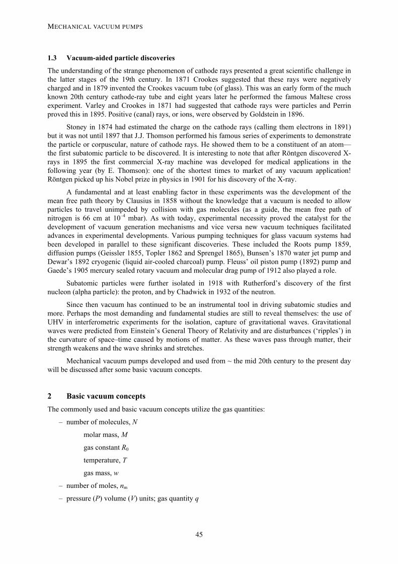
3 Mechanical pumps A classification for mechanical pumps of speeds > 1 m3/h is shown in Fig. 8.
• Wet pumps– Oil sealed rotary vane Primary n = 0 to 3 (m3/h) – Piston Primary n = 0 to 2 (m3/h) – Liquid ring Primary n = 1 to 3 (m3/h)
• Dry Pumps– Northey-claw
- Primary n = 1 to 3 (m3/h)
– Roots Primary or Secondary n = 2 to 5 (m3/h) – Scroll Primary n = 1 to 3 (m3/h) – Screw Primary n = 1 to 3 (m3/h) – Regenerative Primary n = 1 to 3 (m3/h) – Piston Primary n = 1 to 2 (m3/h) – Diaphragm Primary n = 0 to 2 (m3/h) – Drag Primary or Secondary n = 0 to 2 (l/s) – Turbomolecular Secondary n = 1 to 4 (l/s)
Primary pumps – exhaust to atmosphere ) Secondary pump – exhaust to a backing (primary pump) Max speeds shown exponent of maximum pump speed 10n (m3/h or l/s)
Fig. 8: Mechanical pump classification scheme
All theses pumps rely on the principle of positive displacement of gas (or vapour) except drag pumps, which exploit molecular drag and turbomolecular pumps (momentum transfer/capture technique). Table 1 indicates some of the range of choices involved between wet (oil-filled) and dry (oil-free) vacuum pumps.
Table 1: Wet and dry pump comparisons
Wet pumps Dry pumps
Capital cost Low High
Oil loss Can be high at > 1 mbar Very low
System contamination Backstream at < 0.1 mbar Very low
Add on costs Oil return/filtration Not necessary
Aggressive process Not suitable Resistant
Purge Sometimes Almost always
A consideration process involving more decision criteria is shown in Fig. 9.
A.D. CHEW
50

Roughing time ?Throughput ? For process?
Ultimate ? Leakage/outgassing?
Cleanliness?
Choose pump size > requirements
Check: acceptable costPump + foreline still meet requirement Or re-define requirements/foreline
£ $ €?
Up-timeService interval? Running Costs?
Fig. 9: Pump choice considerations
4 Oil-sealed rotary vane pumps Oil-sealed rotary vane pumps (OSRVs shown in Fig. 10) were first developed in the early 1900s. Today, the two commonly used oil-sealed pumps are rotary vane and rotary piston pumps. Oil-sealed rotary vane pumps are often used for low inlet pressures and light gas loads. Oil-sealed rotary piston pumps are often large and are most often found in high-gas-load, high-inlet-pressure industrial applications.
EXHAUSTOUTLET
EXHAUSTVALVE
STATOR
ROTOR
VANE
OIL
INLET
Fig. 10: Basic OSRV schematic
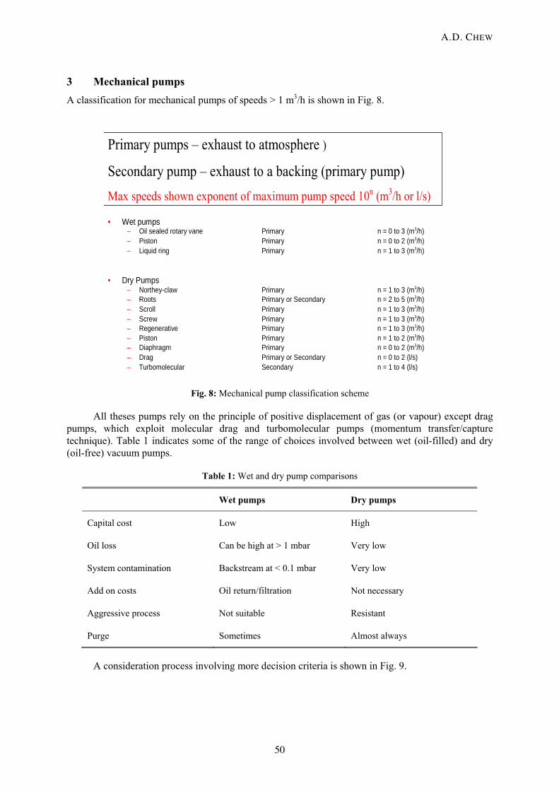
The OSRV pumping cycle is shown in Fig. 11.
MECHANICAL VACUUM PUMPS
51
1 Inlet exposed2 Trapped volume3 Compression4 Exhaust
1 2
34
1 2
34
Fig. 11: OSRV pumping cycle
4.1 Functions of oil
The oil in OSRV and piston pumps has several functions:
– sealing: the oil surface tension seals the duo-seal and fills the gaps between the vanes, rotors, and stators;
– lubrication: of the bearing areas and blade contact surfaces;
– cooling: removes heat from rotors and stators;
– protects parts from rust and corrosion: coats and ‘seals’ surfaces to protect from aggressive gas.
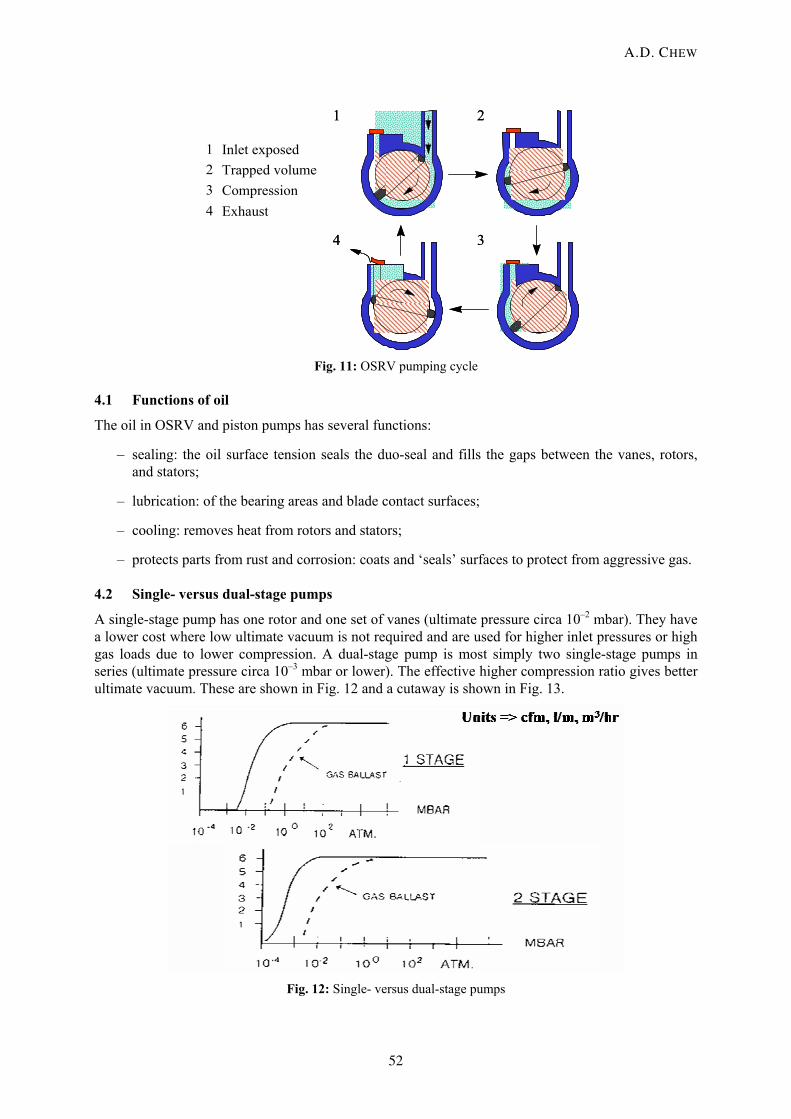
4.2 Single- versus dual-stage pumps
A single-stage pump has one rotor and one set of vanes (ultimate pressure circa 10–2 mbar). They have a lower cost where low ultimate vacuum is not required and are used for higher inlet pressures or high gas loads due to lower compression. A dual-stage pump is most simply two single-stage pumps in series (ultimate pressure circa 10–3 mbar or lower). The effective higher compression ratio gives better ultimate vacuum. These are shown in Fig. 12 and a cutaway is shown in Fig. 13.
Fig. 12: Single- versus dual-stage pumps
A.D. CHEW
52

Fig. 13: OSRV pump cutaway view
4.3 OSRV gas loads
Pumped gas may contain both permanent gases and vapours, which can condense when compressed. Condensed vapours may include liquid water and solvents which can mix with pump oil to form an emulsion. Condensed vapours can limit the ultimate vacuum, cause corrosion, and possibly lead to pump seizure. Gas ballasting allows vapour pumping without condensation. The basic principle is that the ballast gas opens the exhaust before compression pressure allows vapours to condense.
5 Dry pumps – clearance mechanisms Dry pumps do not have oil in the swept pumping volume and use a series of stages with small non-contacting clearances to displace gas/vapours and create compression. Ultimates can be 10–2 mbar and lower; higher frequencies giving lower ultimates as they provide reduced (ultimate-limitating) gas back-leakage. A typical design is shown in Fig.14.
Dry pump: ultimate 0.001 mbar
CannedM otor
C law sM ulti-LobeRootsCooling
G ear
H eadplate
5th 4th 3rd 2nd 1st
Bearing
Seal
Roots
Clearance mechanism Fig. 14: Roots–claw dry pump schematic
MECHANICAL VACUUM PUMPS
53

5.1 Diaphragm pumps
Figure 15 shows the schematic of a diaphragm pump whose best ultimates are of the order 0.1 mbar.
The crankshaft rotates and the connecting rod pulls the diaphragm down, creating a vacuum in the chamber. This opens the inlet valve and closes the exhaust valve and the chamber fills with gas. As the crankshaft continues to rotate, the connecting rod forces the diaphragm to the top of the chamber. This compresses the gas, opens the outlet valve, and closes the inlet valve. The valves on the inlet and outlet to the chamber are flapper types, which are operated by pressure. Figure 16 shows a typical speed curve.
Fig. 15: Diaphragm pump operation schematic
Fig. 16: Vacuubrand/BOC Edwards MD1/XDD1 diaphragm pump speed curve
A.D. CHEW
54

5.2 Scroll pumps
Eccentrically mounted matching scroll forms move to isolate gas and transport it to an atmospheric pressure exhaust as in Fig. 17.
Fig. 17: Isolation of gas in scroll pump mechanism
A typical scroll pump speed curve is shown in Fig. 18.
BOCE XDS35i
Fig. 18: BOC Edwards XDS35i speed curve
5.3 Dry piston pumps
The operational principle of dry piston pumps is the same as with oil-filled versions and is shown in Fig. 19. In the ‘dry’ version contact can be made with ‘sacrificial’ coatings.
MECHANICAL VACUUM PUMPS
55
Inlet Exhaust
Crankshaft
Trapped GasExhausted GasCompressed Gas
Fig. 19: Dry piston pump
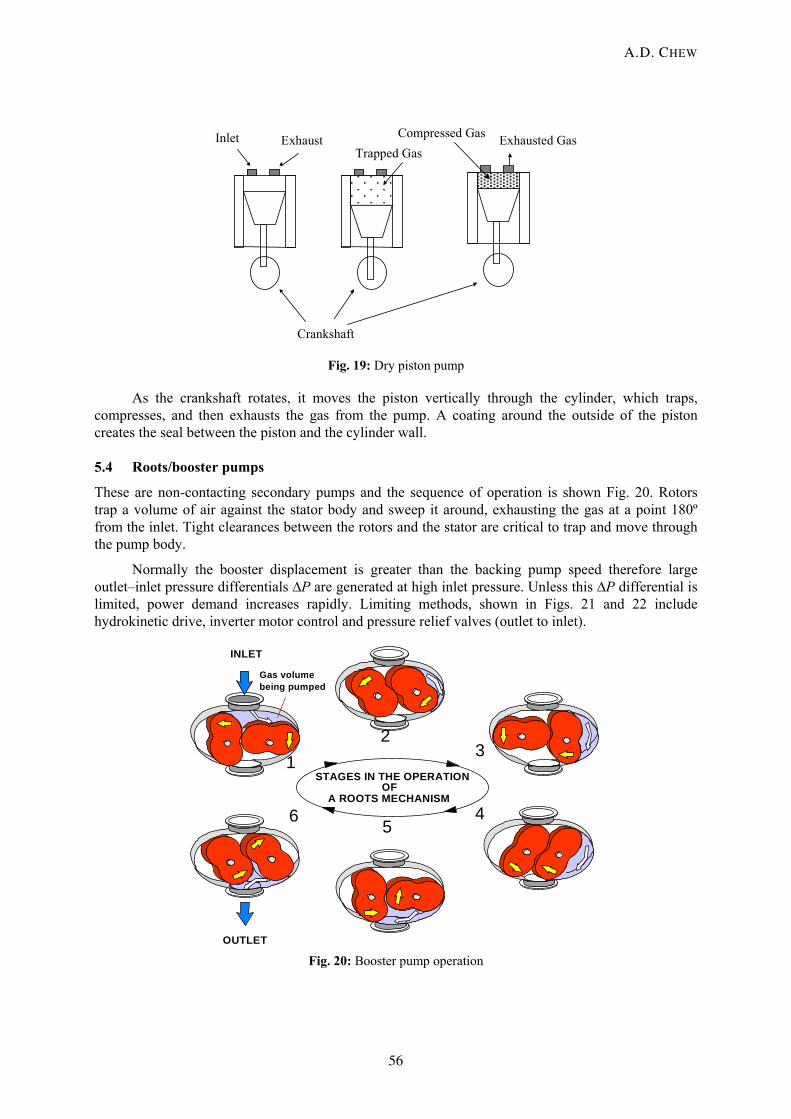
As the crankshaft rotates, it moves the piston vertically through the cylinder, which traps, compresses, and then exhausts the gas from the pump. A coating around the outside of the piston creates the seal between the piston and the cylinder wall.
5.4 Roots/booster pumps
These are non-contacting secondary pumps and the sequence of operation is shown Fig. 20. Rotors trap a volume of air against the stator body and sweep it around, exhausting the gas at a point 180º from the inlet. Tight clearances between the rotors and the stator are critical to trap and move through the pump body.
Normally the booster displacement is greater than the backing pump speed therefore large outlet–inlet pressure differentials ∆P are generated at high inlet pressure. Unless this ∆P differential is limited, power demand increases rapidly. Limiting methods, shown in Figs. 21 and 22 include hydrokinetic drive, inverter motor control and pressure relief valves (outlet to inlet).
STAGES IN THE OPERATION
A ROOTS MECHANISM
OUTLET
INLET
1
12
3
456
Gas volumebeing pumped
OF
Fig. 20: Booster pump operation
A.D. CHEW
56

10001001010.1Pressure
0.010.001
Speed Hydrokinetic driveOr bypass valve orInverter drive
Direct drive driveNo bypass Backing pump
Speed
Fig. 21: Mechanical booster limiting methods
10001001010.1Pressure
0.010.001
Pressure differential
SpeedIncreasing
motor power
IncreasingΔP
capability
Fig. 22: Mechanical booster ∆P versus power
To achieve speed, ultimate or pump-down requirements, more than one booster may be used. With boosters in parallel, performance improvement is limited to approximately one decade improvement in ultimate with modest improvement in pumping speed at high pressures and with high pumping speed improvement at low pressures. With boosters in series, a lower ultimate is achieved (limited by outgassing and back-leakage). Also higher pumping speeds at higher pressures are achieved. This configuration limits the pumping speed at lower pressures. Schematically these are shown in Fig. 23.
MECHANICAL VACUUM PUMPS
57

B
B
B
Pressure
Speed
B
Fig. 23: Schematic of boosters in series and parallel
6 Turbomolecular pumps The internal configuration of a bladed and compound/‘drag’ turbomolecular (secondary) pump is shown in Fig. 24. They can generally achieve UHV and exhaust to approximately 0.1 mbar. Different configurations and compound drag stages can increase throughputs and exhaust pressures significantly (> 20 mbar).
Fig. 24: Compound turbomolecular pump
A.D. CHEW
58

6.1 Principle of operation
This is shown in Figs. 25 to 30 below.
Surface
Molecules leaving surface
1. The direction of the arrow indicates the direction of travel of the molecule. 2. The length of the arrow indicates the ‘probability’ that the molecule will depart in that direction - Knudsen
Fig. 25: Principle of operation
θ
⊥r
pII
P
⊥r
pII
B A
N
(a) (b)
Consider (a) text book collision and (b) reality
High rotational speeds (> 1000 Hz) tip velocity = molecular thermalvelocities
Fig. 26: Molecular collisions with surfaces
MECHANICAL VACUUM PUMPS
59

In the position shown, there is a higher probability that the molecules will leave the blade in a downward direction.
Turbomolecular pump blade
Horizontal
Direction of rotation of blade
Blade speed needs to be of same order as molecular velocity to influence motion
Fig. 27: Molecules leaving a surface
Stator Direction of rotation of blade
Fig. 28: Molecules leaving rotors/stators
A.D. CHEW
60
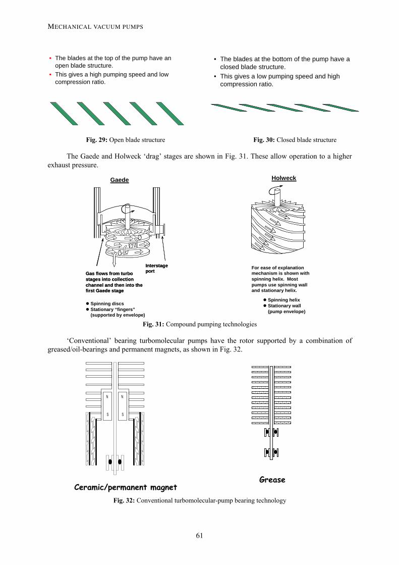
• The blades at the top of the pump have an open blade structure.
• This gives a high pumping speed and low compression ratio.
• The blades at the bottom of the pump have a closed blade structure.
• This gives a low pumping speed and high compression ratio.
Fig. 29: Open blade structure Fig. 30: Closed blade structure
The Gaede and Holweck ‘drag’ stages are shown in Fig. 31. These allow operation to a higher exhaust pressure.
Spinning discs Stationary “fingers” (supported by envelope)
Gaede
Gas flows from turbo stages into collection channel and then into the first Gaede stage
Interstage port Gas flows from turbo
stages into collection channel and then into the first Gaede stage
Interstage port
Holweck
Spinning helix Stationary wall (pump envelope)
For ease of explanation mechanism is shown with spinning helix. Most pumps use spinning wall and stationary helix.
Fig. 31: Compound pumping technologies
‘Conventional’ bearing turbomolecular pumps have the rotor supported by a combination of greased/oil-bearings and permanent magnets, as shown in Fig. 32.
Ceramic/permanent magnetGrease
N
S
N
S
Fig. 32: Conventional turbomolecular-pump bearing technology
MECHANICAL VACUUM PUMPS
61

Magnetic levitation turbomolecular pumps shown in Fig. 33 are generally more expensive but are non-contacting with the following advantages:
– no bearings to wear and – high reliability – permanently low vibration characteristic with time – no hydrocarbon lubricants present – can be mounted in any orientation – designed to work with (harsh) semiconductor process gases, radiation environments, etc.
Z
Y
X1
1
Y
X2
2
PLANE 2
PLANE 1
Z
Y
X1
1
PLANE 1
N S N S
S N S N
3 active axis 5 active axis Cross sectionof 5 – axis STP
Fig. 33: Magnetic bearing turbomolecular pumps
A BOC Edwards STPA2203 (nominal speed 2200 l/s) is shown in Fig. 34 with respect to its throughput performance
Fig. 34: BOC Edwards STPA2203 throughput performance
A.D. CHEW
62

Other pumps designed for mass spectrometry: ‘split flow’/multi-inlet pumps Ref. [1] and pure drag pumps are also extensively used, especially in machinery for scientific instrumentation.
7 Regenerative/drag pump This pump is a single-axis mechanical clearance pump capable of achieving < 10–6 mbar and exhausting directly to atmospheric pressure. It is fully described in Ref. [2] and a cross-section shown in Fig. 35.
Holweck Stages
Rotor
Stator Regenerative stages
Fig. 35: Cross-section of the regenerative/drag (EPX) pump
The pump employs a combination of Holweck drag stages (which enable the achievement of the low ultimate and the molecular pumping speed—up to 140 l/s) and ‘regenerative’ stages which operate from a few mbar to atmospheric exhaust pressure. Figure 36 shows the pumping speed curves for a BOC Edwards EPX500 pump which show the typical molecular nature of the pump’s performance.
0
100
200
300
400
500
600
1.00E-06 1.00E-05 1.00E-04 1.00E-03 1.00E-02 1.00E-01 1.00E+00 1.00E+01 1.00E+02 1.00E+03
Pressure mbar
Spee
d m
3 /hr
Ar
N2
He
H2
Fig. 36: EPX500 speed curves for different gases
MECHANICAL VACUUM PUMPS
63

References [1] A. D. Chew, A. Cameron, D. Goodwin, J. Hamilton, T. Hawley-Jones, P. Meares, J. Pumfrey,
J. Ramsden and D. Steele, Considerations for primary vacuum pumping in mass spectrometry systems, Spectroscopy 20, January 2005.
[2] A. D. Chew, M. Galtry, R. G. Livesey and I. Stones, Towards the single pump solution: Recent development in high speed machines for dry vacuum pumping, J. Vac. Sci. Technol. A 23 (2005) 1314.
A.D. CHEW
64