Embed Size (px)
Citation preview
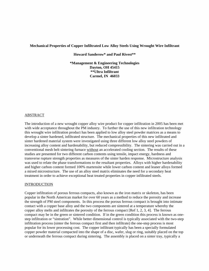
Mechanical Properties of Copper Infiltrated Low Alloy Steels Using Wrought Wire Infiltrant
Howard Sanderow* and Paul Rivest**
*Management & Engineering Technologies Dayton, OH 45415 **Ultra Infiltrant Carmel, IN 46033
ABSTRACT The introduction of a new wrought copper alloy wire product for copper infiltration in 2005 has been met with wide acceptance throughout the PM industry. To further the use of this new infiltration technology this wrought wire infiltration product has been applied to low alloy steel powder matrices as a means to develop a sinter hardened, infiltrated structure. The mechanical properties of this new infiltrated and sinter hardened material system were investigated using three different low alloy steel powders of increasing alloy content and hardenability, but reduced compressibility. The sintering was carried out in a conventional mesh belt sintering furnace without an accelerated cooling section. The results of these studies are presented for two different carbon contents using tensile, impact energy, hardness and transverse rupture strength properties as measures of the sinter harden response. Microstructure analysis was used to relate the phase transformations to the resultant properties. Alloys with higher hardenability and higher carbon content formed 100% martensite while lower carbon content and leaner alloys formed a mixed microstructure. The use of an alloy steel matrix eliminates the need for a secondary heat treatment in order to achieve exceptional heat treated properties in copper infiltrated steels. INTRODUCTION Copper infiltration of porous ferrous compacts, also known as the iron matrix or skeleton, has been popular in the North American market for over 60 years as a method to reduce the porosity and increase the strength of PM steel components. In this process the porous ferrous compact is brought into intimate contact with a copper base alloy and the two components are sintered at a temperature whereby the copper alloy melts and infiltrates the porosity of the ferrous compact [Ref 1, 2, 3, 4]. The ferrous compact may be in the green or sintered condition. If in the green condition this process is known as one-step infiltration or “sintration”. While better dimensional control is typically associated with the two-step infiltration process (sinter the ferrous compact first and then infiltrate) the one-step process is most popular for its lower processing cost. The copper infiltrant typically has been a specially formulated copper powder material compacted into the shape of a disc, wafer, slug or ring, suitably placed on the top or underneath the ferrous compact during sintering. The assembly is placed on a sinter tray, typically a
graphite or ceramic plate, to support the assembly and prevent molten copper from possibly dripping on the sintering belt and causing damage. The molten copper is drawn into the interconnected pores of the ferrous matrix by capillary action. The capillary pressure varies inversely with pore diameter and indirectly with the surface energy of the infiltrating liquid and the contact angle. Therefore the infiltrating alloy should be designed to have good wettability and fluidity, low surface energy (limited solubility of the two materials or formation of an intermediate phase). Since smaller pores have greater capillary force these are filled first and more completely than larger pores. When there is some mutual solubility of the matrix into the infiltrant, as in the case of iron and copper, the infiltrant composition is modified to limit the dissolution of the matrix by matching the equilibrium composition of the infiltrant to that of the matrix at the infiltrating temperature. Most commercial powdered infiltrants contain several weight percent iron to minimize erosion during infiltration. In addition it is generally desirable to limit the effects of the mutual solubility by keeping the infiltration time period short and the infiltration temperature sufficiently low. Finally it is extremely important that the surface of the ferrous matrix be clean, oxide-free and soot-free to ensure proper wetting by the molten infiltrant. Ferrous PM components are copper infiltrated in order to improve physical or mechanical properties as noted below [Ref. 1]. Tensile strength, ductility and impact resistance Improved machinability Improved thermal conductivity Provide pressure tightness for leak-free operation in hydraulic applications Seal porosity for secondary operations such as plating Selective property improvement through localized infiltration In 2005 Ultra Infiltrant introduced a new copper infiltration product based on a wrought copper alloy system (patent pending). This fully prealloyed wire product is supplied cut to length or coiled for precise size and weight control for ease of placement with the ferrous matrix. The rigid wrought infiltrant preform allows for ease of handling, precise placement and 100% product usage. Problems with the fragile, easily fractured or damaged powdered infiltrant are eliminated, cutting the scrap rate to zero. In addition to the processing issues described above the new wrought copper infiltrant eliminates the need for a separate set of tools to press the infiltrant as well as the press to compact the infiltrant and the personnel to monitor and handle the fragile powdered infiltrant. Storage and transport of these delicate compacted infiltrant performs is also removed from the processing route, replaced by a robust, rigid, easily handled wrought wire infiltrant. Previous investigation of this new product [5] found an excellent infiltration response with no residue on the part surface, mechanical properties that far exceed the values listed in MPIF Standard 35 and the ability to achieve less than 5% porosity when using the FX-1008 composition. Tensile strength of 880 MPa (127,000 psi) with 3% elongation, 16 J (12 ft-lbf) impact energy and 27 HRC apparent hardness were reported for the FX-1008 grade at an infiltrated density of 7.70 g/cc. OBJECTIVE The goal of this new study was to extend the mechanical properties of this new infiltration product by using low alloy steel powder as the matrix, rather than plain iron powder. Due to the excellent infiltration behavior reported previously [5] it was believed that a sinter hardened structure could be developed
without the need for an accelerated cooling zone in the sintering furnace. This would allow all current manufacturers to extend their product capabilities without the need to add new sintering equipment. The goal of this study was to determine the physical and mechanical response of the new wrought wire copper infiltrant when coupled with three different low alloy steel matrices of differing composition and hardenability, as a function of two different combined carbon levels. EXPERIMENTAL PROCEDURE Three different low alloy steel powders were selected for this investigation. The alloy composition ranged from lean to highly alloyed and thereby provided a range of responses based on hardenability, compressibility and powder cost. The base powders were Hoeganaes Ancorsteel 50HP, Ancorsteel 2000 and Ancorsteel 4600V. The six blends used 0.6% Southwest 1651 graphite and 0.85% Southwest 1651 graphite with each base powder; 0.75% Acrawax C was admixed as the lubricant. Each powder was compacted at 40 tsi. The resultant green density varied due to the amount of graphite in the mix and the compressibility of the base powder. Four tensile, TRS and Charpy impact test specimens, conforming to MPIF Standards 10, 41 and 40, were prepared using each powder blend. The wire infiltrant provided by Ultra Infiltrant was placed on top of the green specimens and then processed using a one-step sinter-infiltration process in a commercial mesh belt sintering furnace at 1125°C (2060°F) with 90% nitrogen -10% hydrogen atmosphere and no accelerated cooling zone. The weight of the wire infiltrant was 13% of the green weight of the test specimen. Following sintering the test bars were tempered in air for 1 hour at 205C (400F). Mechanical properties (tensile, TRS, hardness and impact energy) and final dimensions were measured for each test specimen in the infiltrated and tempered condition with no effort to clean or abrade the specimen surface. Optical microscopy was used to characterize the microstructure of the TRS test specimens, both at the surface and in the interior of the test specimen cross section. RESULTS
Green Properties The green density, weight and dimensions of each test specimen were recorded to serve as a basis for comparison to the sintered and infiltrated results. As expected, the green density of the six powder blends responded directly to the amount of graphite in the mix and the compressibility of the base powder (see Table 1). The 50HP mixes reached the highest green density while the 4600V mixes were the lowest in green density.
Table 1 – Compressibility of the Steel Matrix Powder Blends
Mix # Powder Blend Alloy Content wt. %
Green Density g/cc
1 Ancorsteel 50HP + 0.6% graphite 0.15%Mn, 0.50%Mo 6.99 2 Ancorsteel 50HP + 0.85% graphite 0.15%Mn, 0.50%Mo 6.96 3 Ancorsteel 4200 + 0.6% graphite 0.30%Mn, 0.45%Ni, 0.65%Mo 6.92 4 Ancorsteel 4200 + 0.85% graphite 0.30%Mn, 0.45%Ni, 0.65%Mo 6.89 5 Ancorsteel 4600V +0.6% graphite 0.15%Mn, 1.85%Ni, 0.50%Mo 6.82 6 Ancorsteel 4600V +0.85% graphite 0.15%Mn, 1.85%Ni, 0.50%Mo 6.80

Sintered/Infiltrated Physical Properties The physical characteristics of the infiltrated test specimens (dimensional change and density) were determined using the TRS bars, tensile bars and the Charpy impact bars (total of 72 test specimens). The results of these measurements are summarized in Table 2.
Table 2 – Physical Properties of Infiltrated Low Alloy Steels
Mix # Matrix Powder Blend Dimensional Change %
Infiltrated Density g/cc
1 Ancorsteel 50HP + 0.6% graphite +0.66 7.69 2 Ancorsteel 50HP + 0.85% graphite +0.37 7.73 3 Ancorsteel 4200 + 0.6% graphite +0.92 7.53 4 Ancorsteel 4200 + 0.85% graphite +0.47 7.61 5 Ancorsteel 4600V +0.6% graphite +1.62 7.29 6 Ancorsteel 4600V +0.85% graphite +0.72 7.51
A review of the dimensional change data finds the least growth for the powder blends that contained the higher graphite content and the lower alloy content. Using the 50HP powder blend as a base for comparison, the 4200 powder blend grew 40% more and the 4600V blend grew nearly 2.5X greater. Clearly the addition of more graphite to each powder blend helped to control dimensional growth. The density results directly followed the trends of the dimensional change data -- the highest density for the higher graphite content blends and the lower alloy content blends. The infiltration process increased the density of the higher graphite content blends to a greater extent than the lower graphite blends, reversing the relative positions seen in the green density data (compare the position of the lower graphite blends in Table 1 to their position in Table 2). Note also the differential between the lower and higher graphite blend was the least for the 50HP blend (only 0.04 g/cc) and much greater for the 4600V base blend (0.22 g/cc). It is clear that metallurgical changes have occurred during the sinter-infiltration process that have affected the degree of densification over and above the difference in compressibility between the three blends. Sintered/Infiltrated Mechanical Properties The mechanical characteristics of the infiltrated test specimens were determined from the TRS bars, tensile bars and the Charpy impact bars (total of 72 test specimens). The results of these measurements are summarized in Table 3.
Table 3 – Mechanical Properties of Infiltrated Low Alloy Steels
Tensile Properties Hardness UTS YS Elongation
TRS Impact Energy As-sinter Tempered
Mix # MPa (psi)
MPa (psi)
%
MPa (psi)
J (ft-lbf)
HRC HRC
1 755 (109,000)
585 (85,000)
1.6 1520 (220,000)
19 (14)
31 31
2 875 (127,000)
645 (93,000)
1.8 1720 (249,000)
22 (16)
34 35
3 755 (110,000)
650 (95,000)
0.9 1350 (196,000)
10 (7)
37 37
4 840 (122,000)
685 (99,000)
1.0 1570 (228,000)
12 (9)
43 40
5 555 (80,000)
-- 0.4 940 (137,000)
4 (3)
42 40
6 705 (102,000)
640 (93,000)
0.6 1170 (170,000)
7 (5)
45 43
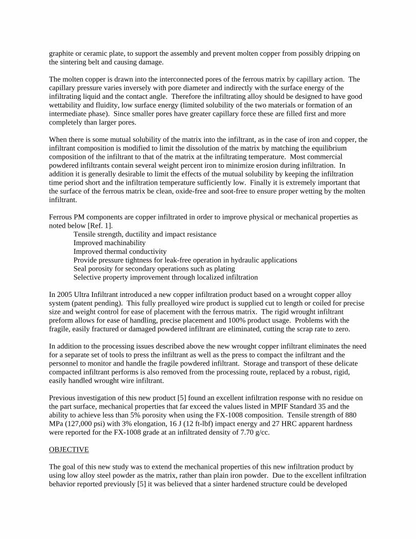
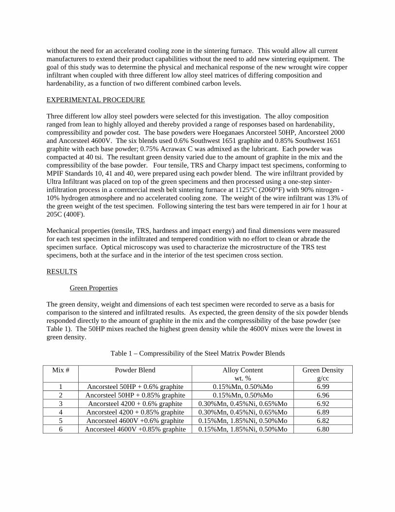
The strength and hardness properties followed the same pattern, regardless of part density. The materials with 0.85% graphite were higher in strength and hardness than the corresponding base low alloy material with only 0.6% graphite. Strength was highest for the material with the lowest hardenability (FL-4000) and lowest for the highest hardenability alloy (FL-4600). Hardness followed the expected relationship – highest hardness for the highest hardenability steel. These results imply that the FL-4600 material sinter hardened to a full martensite structure while the FL-4000 did not form very much martensite on cooling from the sintering process. The intermediate alloy, FL-4200 apparently yielded a greater amount of martensite than the FL-4000 grade but less than the FL-4600. The impact energy results followed the same relationship as the strength data – the higher graphite content materials were higher in impact energy than the same base material with the 0.6% graphite. In addition the leanest alloy, FL-4000 had the highest impact energy results 19 and 22 J while the highly alloyed FL-4600 blends had only 4 and 7 J impact energy. Thus the compositions that formed more martensite appear to have lower impact results. Sintered/Infiltrated Metallurgical Properties The results of the metallurgical investigations are shown in the following microstructures. A critical analysis of the phase constituents identified at both the surface and the interior of the test specimens is summarized in Table 4. The lamellar structure typical of prealloyed steels is identified as pearlite. A dark, unresolved colony is called upper bainite or fine pearlite. If this colony appears feathery it is identified as lower bainite. Martensite can be lightly etched or darker depending on the powder mix, but is generally acicular. Large amounts of retained austenite were found in mix #6 at the surface and appeared as white regions dispersed in the martensite. In all cases the constituents were estimated based on the ferrous portion of the microstructure (no pores, no copper). Each figure is a composite of four individual photomicrographs – the top two photos illustrate the surface of the sample with a free edge evident (top left at 250X and top right at 800X magnification) and the bottom two photos illustrate the interior of the sample, again with the bottom left view at 250X and the bottom right at 800X.

Mix #1 (Figure 1) The leanest alloy with the lowest carbon content was predominantly pearlite both at the surface and the interior of the sample. Minor amounts of fine pearlite and martensite were noted. This structure is most similar to the structure found when using a plain carbon steel matrix (FX-1008). Mix #2 (Figure 2) Increasing the carbon content from 0.6% (mix #1) to 0.85% (mix #2) while using the leanest alloy significantly changed the microstructure from predominantly pearlite seen in Figure 1 to a mixture of martensite and fine pearlite/upper bainite seen in Figure 2. The surface region of mix #2 was predominantly martensite and then changed to predominantly fine pearlite/upper bainite in the interior. Even wit the increase in carbon content the lean alloy did not have sufficient hardenability to transform to a martensite structure in the interior of the specimen. Mix #3 (Figure 3) Changing to a slightly higher hardenability alloy for mix #3 (from FL-4000 in mix #1 to FL-4200 in mix #3) had major effect at the lower carbon level. Figure 3 shows a mixed structure at both the surface and interior with mainly martensite and fine pearlite/upper bainite. The martensite phase is slightly greater at the surface than the interior, becoming the less dominant phase in the interior portion of the specimen. This compares to the leaner alloy in mix #1 which formed mainly pearlite both at the surface and the interior (compare Figure 1 with Figure 3 for the effect of changing alloy content of the matrix material). Mix #4 (Figure 4) Using the higher hardenability FL-4200 prealloyed powder plus the higher carbon content produced even more martensite both at the surface and interior than found in mix #3 and seen in Figure 3. The structure found in Figure 4 is predominantly martensite at the surface and nearly 50% martensite in the interior. Though still a mixed microstructure the hardness and strength of this system would be affected by the predominant martensite phase, as compared to the previous specimens where martensite was not the predominant phase. The microstructure phase distribution is mix #4 most closely matches the results seen from mix #2 (compare results in Figure 2 and Figure 4, and listed in Table 4). Mix #5 (Figure 5) Changing to the highest hardenability prealloyed powder for mix #5 completely changed the microstructure, as seen in Figure 5, to 100% martensite at the surface and only small amounts of bainite with the martensite in the interior. The combination of 0.6% carbon and the FL-4600 prealloyed powder was sufficient to produce a fully martensitic structure without the use of a rapid cooling zone in this material. Mix #6 (Figure 6) Increasing the carbon content to 0.85% in the FL-4600 material for mix #6 again yielded a martensitic structure but the extra carbon created a sluggish transformation with about 15% retained austenite at the surface and additional lower transformation products in the interior. The use of the higher added graphite to this prealloyed powder did not provide the desired 100% martensite microstructure, but rather a greater amount of lower transformation products than seen in mix #5 with less carbon.
Figure 1 Mix #1, exterior surface of specimen illustrated in top photos, interior in bottom photos; 2% nital
Figure 2 Mix #2, exterior surface of specimen illustrated in top photos, interior in bottom photos; 2% nital
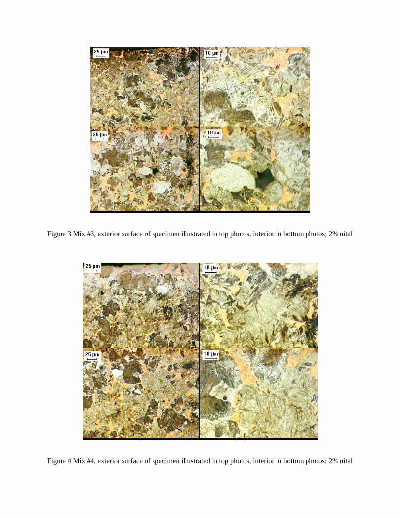
Figure 3 Mix #3, exterior surface of specimen illustrated in top photos, interior in bottom photos; 2% nital
Figure 4 Mix #4, exterior surface of specimen illustrated in top photos, interior in bottom photos; 2% nital
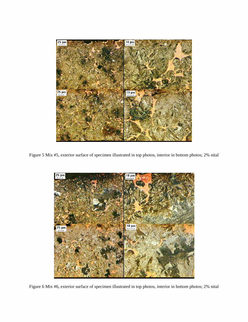
Figure 5 Mix #5, exterior surface of specimen illustrated in top photos, interior in bottom photos; 2% nital
Figure 6 Mix #6, exterior surface of specimen illustrated in top photos, interior in bottom photos; 2% nital
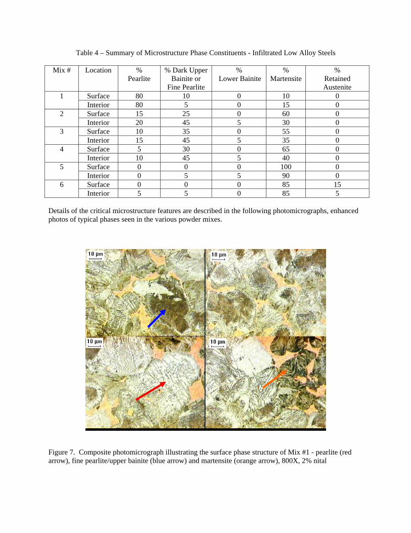
Table 4 – Summary of Microstructure Phase Constituents - Infiltrated Low Alloy Steels
Mix # Location % Pearlite
% Dark Upper Bainite or
Fine Pearlite
% Lower Bainite
% Martensite
% Retained Austenite
Surface 80 10 0 10 0 1 Interior 80 5 0 15 0 Surface 15 25 0 60 0 2 Interior 20 45 5 30 0 Surface 10 35 0 55 0 3 Interior 15 45 5 35 0 Surface 5 30 0 65 0 4 Interior 10 45 5 40 0 Surface 0 0 0 100 0 5 Interior 0 5 5 90 0 Surface 0 0 0 85 15 6 Interior 5 5 0 85 5
Details of the critical microstructure features are described in the following photomicrographs, enhanced photos of typical phases seen in the various powder mixes.
Figure 7. Composite photomicrograph illustrating the surface phase structure of Mix #1 - pearlite (red arrow), fine pearlite/upper bainite (blue arrow) and martensite (orange arrow), 800X, 2% nital

Figure 8. Composite photomicrograph illustrating the interior phase structure of Mix #4, highlighting pearlite (red arrow), fine pearlite/upper bainite (blue arrow), lower bainite (green arrow) and martensite (orange arrow), 800X, 2% nital
Figure 9. Composite photomicrograph illustrating the surface phase structure of Mix #6, highlighting martensite (orange arrow) and retained austenite (purple arrow), 800X, 2% nital
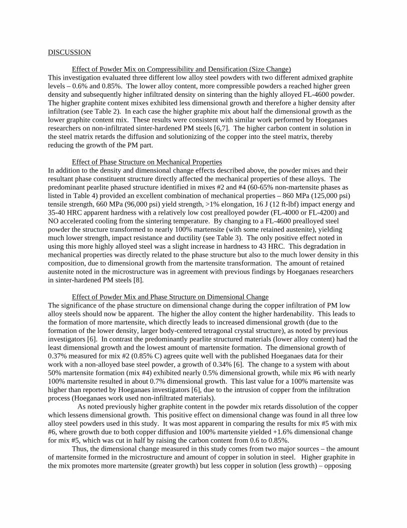
DISCUSSION Effect of Powder Mix on Compressibility and Densification (Size Change) This investigation evaluated three different low alloy steel powders with two different admixed graphite levels – 0.6% and 0.85%. The lower alloy content, more compressible powders a reached higher green density and subsequently higher infiltrated density on sintering than the highly alloyed FL-4600 powder. The higher graphite content mixes exhibited less dimensional growth and therefore a higher density after infiltration (see Table 2). In each case the higher graphite mix about half the dimensional growth as the lower graphite content mix. These results were consistent with similar work performed by Hoeganaes researchers on non-infiltrated sinter-hardened PM steels [6,7]. The higher carbon content in solution in the steel matrix retards the diffusion and solutionizing of the copper into the steel matrix, thereby reducing the growth of the PM part. Effect of Phase Structure on Mechanical Properties In addition to the density and dimensional change effects described above, the powder mixes and their resultant phase constituent structure directly affected the mechanical properties of these alloys. The predominant pearlite phased structure identified in mixes #2 and #4 (60-65% non-martensite phases as listed in Table 4) provided an excellent combination of mechanical properties – 860 MPa (125,000 psi) tensile strength, 660 MPa (96,000 psi) yield strength, >1% elongation, 16 J (12 ft-lbf) impact energy and 35-40 HRC apparent hardness with a relatively low cost prealloyed powder (FL-4000 or FL-4200) and NO accelerated cooling from the sintering temperature. By changing to a FL-4600 prealloyed steel powder the structure transformed to nearly 100% martensite (with some retained austenite), yielding much lower strength, impact resistance and ductility (see Table 3). The only positive effect noted in using this more highly alloyed steel was a slight increase in hardness to 43 HRC. This degradation in mechanical properties was directly related to the phase structure but also to the much lower density in this composition, due to dimensional growth from the martensite transformation. The amount of retained austenite noted in the microstructure was in agreement with previous findings by Hoeganaes researchers in sinter-hardened PM steels [8]. Effect of Powder Mix and Phase Structure on Dimensional Change The significance of the phase structure on dimensional change during the copper infiltration of PM low alloy steels should now be apparent. The higher the alloy content the higher hardenability. This leads to the formation of more martensite, which directly leads to increased dimensional growth (due to the formation of the lower density, larger body-centered tetragonal crystal structure), as noted by previous investigators [6]. In contrast the predominantly pearlite structured materials (lower alloy content) had the least dimensional growth and the lowest amount of martensite formation. The dimensional growth of 0.37% measured for mix #2 (0.85% C) agrees quite well with the published Hoeganaes data for their work with a non-alloyed base steel powder, a growth of 0.34% [6]. The change to a system with about 50% martensite formation (mix #4) exhibited nearly 0.5% dimensional growth, while mix #6 with nearly 100% martensite resulted in about 0.7% dimensional growth. This last value for a 100% martensite was higher than reported by Hoeganaes investigators [6], due to the intrusion of copper from the infiltration process (Hoeganaes work used non-infiltrated materials). As noted previously higher graphite content in the powder mix retards dissolution of the copper which lessens dimensional growth. This positive effect on dimensional change was found in all three low alloy steel powders used in this study. It was most apparent in comparing the results for mix #5 with mix #6, where growth due to both copper diffusion and 100% martensite yielded +1.6% dimensional change for mix #5, which was cut in half by raising the carbon content from 0.6 to 0.85%. Thus, the dimensional change measured in this study comes from two major sources – the amount of martensite formed in the microstructure and amount of copper in solution in steel. Higher graphite in the mix promotes more martensite (greater growth) but less copper in solution (less growth) – opposing
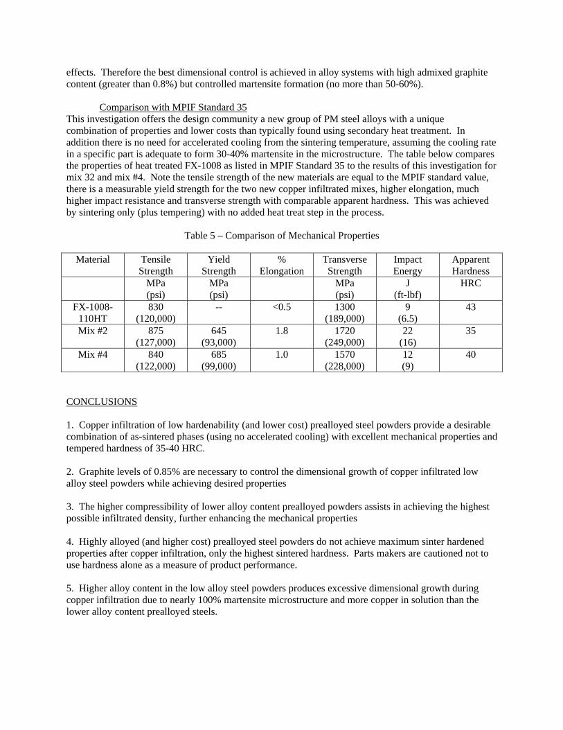
effects. Therefore the best dimensional control is achieved in alloy systems with high admixed graphite content (greater than 0.8%) but controlled martensite formation (no more than 50-60%). Comparison with MPIF Standard 35 This investigation offers the design community a new group of PM steel alloys with a unique combination of properties and lower costs than typically found using secondary heat treatment. In addition there is no need for accelerated cooling from the sintering temperature, assuming the cooling rate in a specific part is adequate to form 30-40% martensite in the microstructure. The table below compares the properties of heat treated FX-1008 as listed in MPIF Standard 35 to the results of this investigation for mix 32 and mix #4. Note the tensile strength of the new materials are equal to the MPIF standard value, there is a measurable yield strength for the two new copper infiltrated mixes, higher elongation, much higher impact resistance and transverse strength with comparable apparent hardness. This was achieved by sintering only (plus tempering) with no added heat treat step in the process.
Table 5 – Comparison of Mechanical Properties
Material Tensile Strength
Yield Strength
% Elongation
Transverse Strength
Impact Energy
Apparent Hardness
MPa (psi)
MPa (psi)
MPa (psi)
J (ft-lbf)
HRC
FX-1008-110HT
830 (120,000)
-- <0.5 1300 (189,000)
9 (6.5)
43
Mix #2 875 (127,000)
645 (93,000)
1.8 1720 (249,000)
22 (16)
35
Mix #4 840 (122,000)
685 (99,000)
1.0 1570 (228,000)
12 (9)
40
CONCLUSIONS 1. Copper infiltration of low hardenability (and lower cost) prealloyed steel powders provide a desirable combination of as-sintered phases (using no accelerated cooling) with excellent mechanical properties and tempered hardness of 35-40 HRC. 2. Graphite levels of 0.85% are necessary to control the dimensional growth of copper infiltrated low alloy steel powders while achieving desired properties 3. The higher compressibility of lower alloy content prealloyed powders assists in achieving the highest possible infiltrated density, further enhancing the mechanical properties 4. Highly alloyed (and higher cost) prealloyed steel powders do not achieve maximum sinter hardened properties after copper infiltration, only the highest sintered hardness. Parts makers are cautioned not to use hardness alone as a measure of product performance. 5. Higher alloy content in the low alloy steel powders produces excessive dimensional growth during copper infiltration due to nearly 100% martensite microstructure and more copper in solution than the lower alloy content prealloyed steels.
6. The sinter-infiltration of low alloy steel powders in a standard cooling zone sintering furnace produces mechanical properties equal to or exceeding the heat treated properties of FX-1008 listed in MPIF Standard 35. REFERENCES 1. P. Samal and E. Klar, “Copper-Infiltrated Steels”, Powder Metal Technologies and Applications, ASM Metals Handbook - Volume 7, 1998, ASM International, Materials Park, OH, p. 769-773. 2. F. V. Lenel, Powder Metallurgy-Principles and Applications, 1980, MPIF, Princeton, NJ, p. 316-317. 3. R. M. German, Powder Metallurgy Science, 2nd Edition, 1994, MPIF, Princeton, NJ, p. 310-312. 4. L. F. Pease, III and W. G. West, Fundamentals of Powder Metallurgy, 2002, MPIF, Princeton, NJ, p. 159-162. 5. H. Sanderow and P. Rivest, “A Unique Form for Copper Infiltration – Wrought Wire Infiltrant”, Advances in Powder Metallurgy and Particulate Materials-2006, compiled by W. R. Gasbarre and J. W. vonArx, MPIF, Princeton, NJ, 2006, Part 6, p. 50-61. 6. B. Lindsley, G. Fillari and T. Murphy, “Effect of Composition and Cooling Rate on Physical Properties and Microstructure of Prealloyed P/M Steels”, Advances in Powder Metallurgy and Particulate Materials-2005, compiled by C. Ruas and T. A. Tomlin, MPIF, Princeton, NJ, 2005, Part 10, p. 353-366. 7. M. C. Baran, A. H. Graham, A. B. Davala, R. J. Causton and C. Schade, “A Superior Sinter-Hardenable Material”, Advances in Powder Metallurgy and Particulate Materials-1999, compiled by C. L Rose and M. H. Thibodeau, MPIF, Princeton, NJ, 1999, Part 7, p. 185-203. 8. T. F. Murphy and M. C. Baran, “An Investigation into the Effect of Copper and Graphite Additions to Sinter-Hardening Steels”, Advances in Powder Metallurgy and Particulate Materials-2004, compiled by R. A. Chernenkoff and W. b. James, MPIF, Princeton, NJ, 2004, Part 10, p. 266-274.