Embed Size (px)
Citation preview

© 2012 ANSYS, Inc. December 19, 2012 1 Release 14.5
Introduction to ANSYS Mechanical
14.5 Release
Lecture 10 Thermal Analysis
© 2012 ANSYS, Inc. December 19, 2012 2 Release 14.5
Chapter Overview
In this chapter, performing steady-state thermal analyses in Mechanical will be covered:
A. Basics of Steady State Heat Transfer
B. Geometry
C. Material Properties
D. Thermal Contact
E. Thermal Boundary Conditions
F. Solution Options
G. Results and Postprocessing
H. Workshop 10.1 – Pump Housing
Note: advanced topics including thermal transient analyses are covered in the ANSYS Mechanical Heat Transfer training course.

© 2012 ANSYS, Inc. December 19, 2012 3 Release 14.5
A. Basics of Steady-State Heat Transfer The schematic setup for a steady-state (static) thermal analysis is shown here.
Later in this chapter we will shown the procedure for setting up a coupled thermal structural analysis.
© 2012 ANSYS, Inc. December 19, 2012 4 Release 14.5
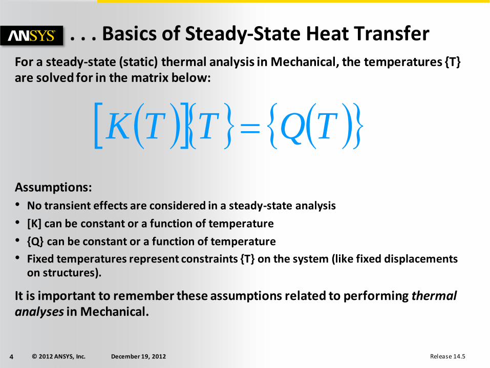
. . . Basics of Steady-State Heat Transfer For a steady-state (static) thermal analysis in Mechanical, the temperatures {T} are solved for in the matrix below:
Assumptions:
• No transient effects are considered in a steady-state analysis
• [K] can be constant or a function of temperature
• {Q} can be constant or a function of temperature
• Fixed temperatures represent constraints {T} on the system (like fixed displacements on structures).
It is important to remember these assumptions related to performing thermal analyses in Mechanical.
TQTTK
© 2012 ANSYS, Inc. December 19, 2012 5 Release 14.5
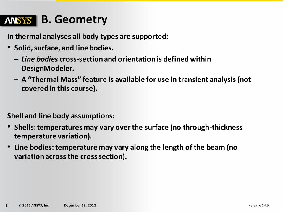
B. Geometry In thermal analyses all body types are supported:
• Solid, surface, and line bodies.
– Line bodies cross-section and orientation is defined within DesignModeler.
– A “Thermal Mass” feature is available for use in transient analysis (not covered in this course).
Shell and line body assumptions:
• Shells: temperatures may vary over the surface (no through-thickness temperature variation).
• Line bodies: temperature may vary along the length of the beam (no variation across the cross section).

© 2012 ANSYS, Inc. December 19, 2012 6 Release 14.5
C. Material Properties
• Thermal Conductivity is
input in the Engineering
Data application
• Temperature-dependent
thermal conductivity is
input as a table
• The only required material property for steady state is thermal
conductivity.

© 2012 ANSYS, Inc. December 19, 2012 7 Release 14.5
D. Thermal Contact As with structural analyses, contact regions are automatically created to enable heat transfer between parts in assemblies.
© 2012 ANSYS, Inc. December 19, 2012 8 Release 14.5
… Thermal Contact
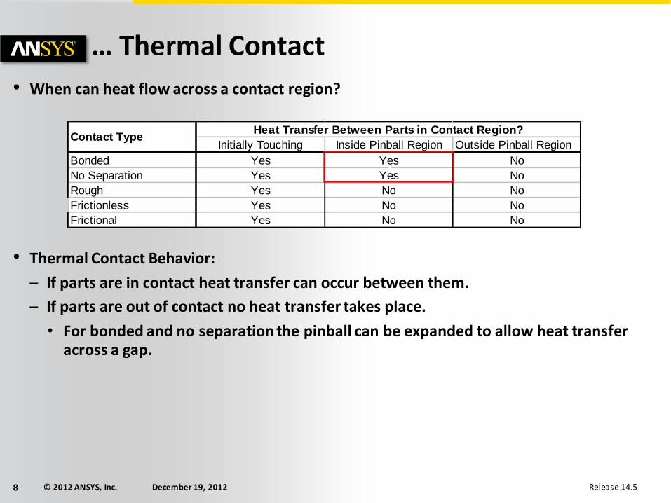
• When can heat flow across a contact region?
• Thermal Contact Behavior:
– If parts are in contact heat transfer can occur between them.
– If parts are out of contact no heat transfer takes place.
• For bonded and no separation the pinball can be expanded to allow heat transfer across a gap.
Initially Touching Inside Pinball Region Outside Pinball Region
Bonded Yes Yes No
No Separation Yes Yes No
Rough Yes No No
Frictionless Yes No No
Frictional Yes No No
Contact TypeHeat Transfer Between Parts in Contact Region?
z

© 2012 ANSYS, Inc. December 19, 2012 9 Release 14.5
… Thermal Contact
If the contact is bonded or no separation, then heat transfer will occur when the surfaces are within the pinball radius.
Pinball Radius
In this figure, the gap between the
two parts is larger than the pinball region, so no heat transfer will
occur between the parts.
© 2012 ANSYS, Inc. December 19, 2012 10 Release 14.5
… Thermal Contact
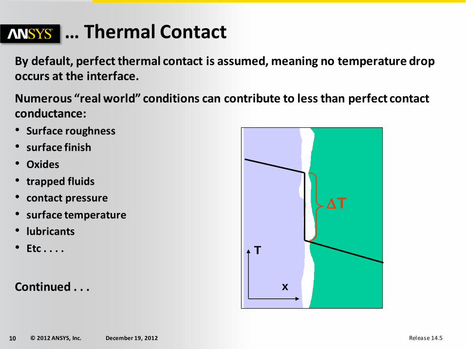
By default, perfect thermal contact is assumed, meaning no temperature drop occurs at the interface.
Numerous “real world” conditions can contribute to less than perfect contact conductance:
• Surface roughness
• surface finish
• Oxides
• trapped fluids
• contact pressure
• surface temperature
• lubricants
• Etc . . . .
Continued . . .
DT
T
x

© 2012 ANSYS, Inc. December 19, 2012 11 Release 14.5
… Thermal Contact
• By default, TCC (Thermal Contact Conductivity) is set to a high value based on the size and material conductivities in the model. This essentially provides ‘perfect’ conductance between parts.
• A lower TCC value can be set in the contact details to provide a thermal resistance.
contacttarget TTTCCq
The amount of heat flow across a contact interface is defined by the contact heat flux expression “q” shown here:
• Tcontact is the temperature of the contact surface and
• Ttarget is the temperature of the target surface.
© 2012 ANSYS, Inc. December 19, 2012 12 Release 14.5
… Thermal Contact
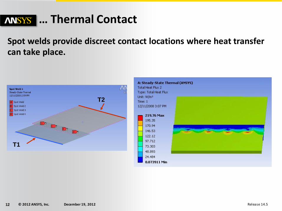
Spot welds provide discreet contact locations where heat transfer can take place.
T1
T2

© 2012 ANSYS, Inc. December 19, 2012 13 Release 14.5
E. Thermal Boundary Conditions
Heat Flow:
• A heat flow rate can be applied to a vertex, edge, or surface.
• Heat flow has units of energy/time.
Heat Flux:
• Heat flux can be applied to surfaces only (edges in 2D).
• Heat flux has units of energy/time/area.
Internal Heat Generation:
• An internal heat generation rate can be applied to bodies only.
• Heat generation has units of energy/time/volume.
A positive value for heat load will add energy to the system.
© 2012 ANSYS, Inc. December 19, 2012 14 Release 14.5
… Thermal Boundary Conditions
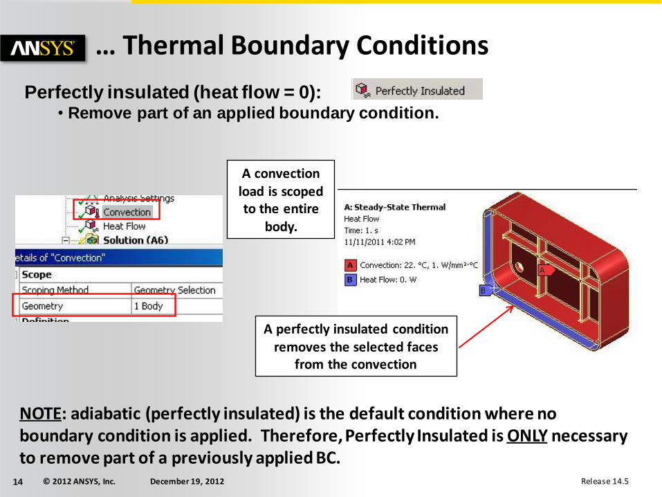
Perfectly insulated (heat flow = 0): • Remove part of an applied boundary condition.
NOTE: adiabatic (perfectly insulated) is the default condition where no boundary condition is applied. Therefore, Perfectly Insulated is ONLY necessary to remove part of a previously applied BC.
A convection load is scoped to the entire
body.
A perfectly insulated condition removes the selected faces
from the convection

© 2012 ANSYS, Inc. December 19, 2012 15 Release 14.5
… Thermal Boundary Conditions
Temperature, Convection and Radiation: – At least one type of thermal condition containing temperature {T} should be present
to bound the problem (prevent the thermal equivalent of rigid body motion).
Temperature:
• Imposes a temperature on vertices, edges, surfaces or bodies.
Convection:
• Ambient temperature
Radiation:
• Ambient temperature
ambientsurfacec TThAq
44
ambientsurfaceR TTFAq
T
© 2012 ANSYS, Inc. December 19, 2012 16 Release 14.5
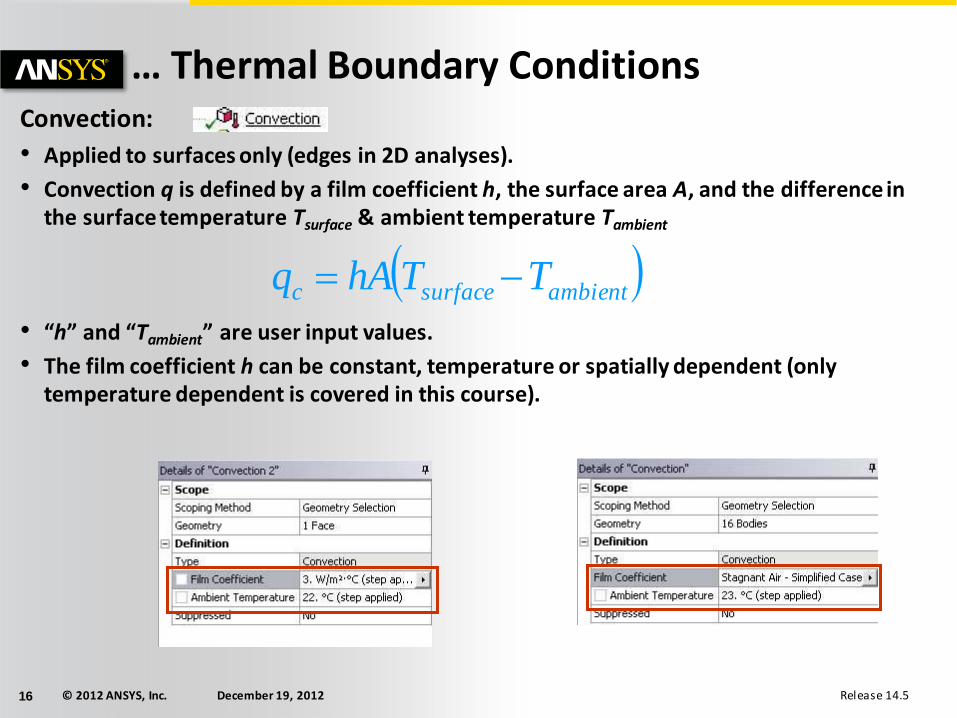
… Thermal Boundary Conditions Convection:
• Applied to surfaces only (edges in 2D analyses).
• Convection q is defined by a film coefficient h, the surface area A, and the difference in the surface temperature Tsurface & ambient temperature Tambient
• “h” and “Tambient” are user input values.
• The film coefficient h can be constant, temperature or spatially dependent (only temperature dependent is covered in this course).
ambientsurfacec TThAq
© 2012 ANSYS, Inc. December 19, 2012 17 Release 14.5
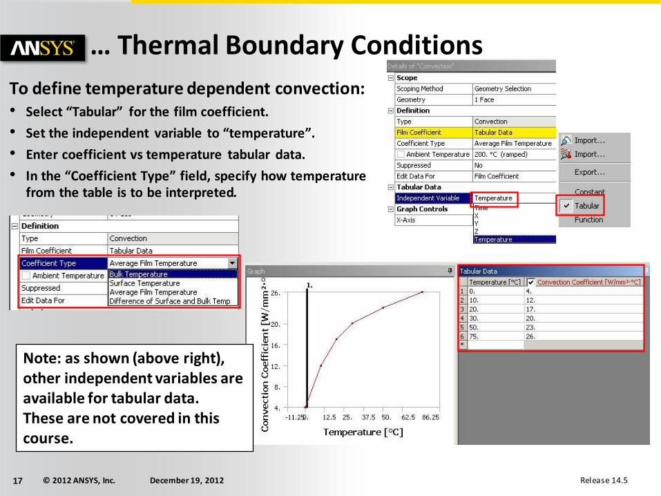
… Thermal Boundary Conditions
To define temperature dependent convection: • Select “Tabular” for the film coefficient.
• Set the independent variable to “temperature”.
• Enter coefficient vs temperature tabular data.
• In the “Coefficient Type” field, specify how temperature from the table is to be interpreted.
Note: as shown (above right), other independent variables are available for tabular data. These are not covered in this course.
© 2012 ANSYS, Inc. December 19, 2012 18 Release 14.5
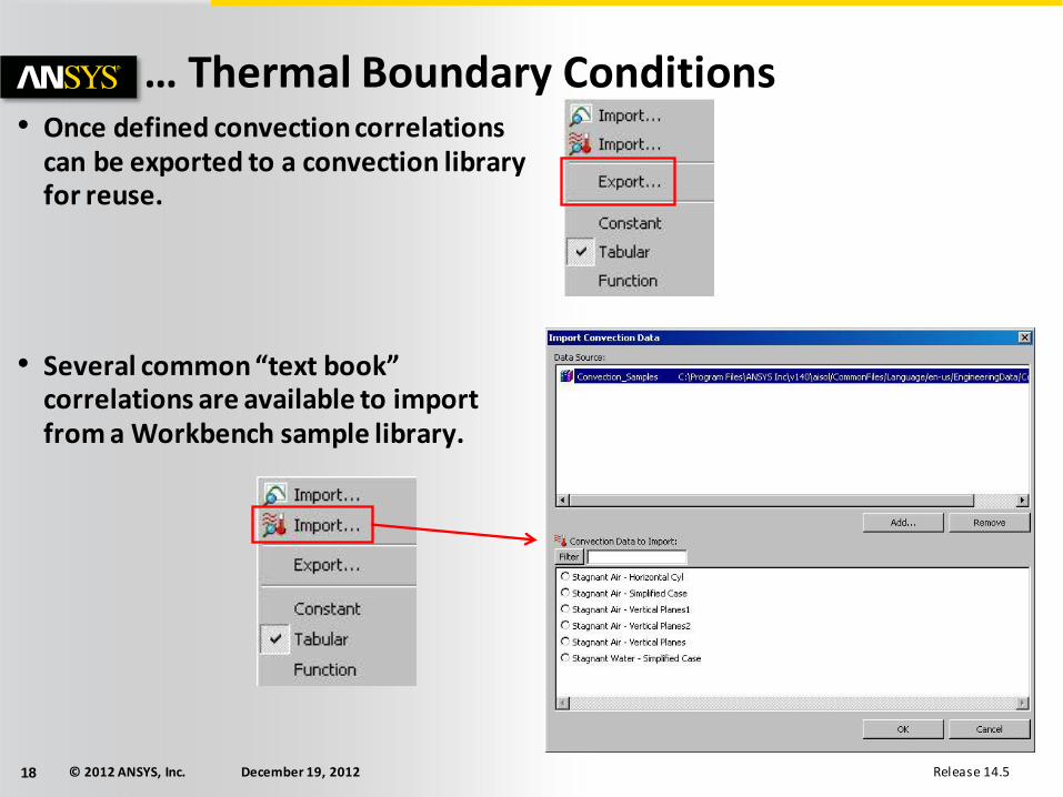
… Thermal Boundary Conditions • Once defined convection correlations
can be exported to a convection library for reuse.
• Several common “text book” correlations are available to import from a Workbench sample library.

© 2012 ANSYS, Inc. December 19, 2012 19 Release 14.5
. . . Thermal Boundary Conditions Radiation:
• Applied to surfaces (edges in 2D analyses)
• Where:
– σ = Stefan-Boltzman constant
– ε = Emissivity
– A = Area of radiating surface
– F = Form factor
• Correlations:
– To ambient (form factor assumed to be 1)
OR
– Surface to surface (view factors calculated).
• Stefan Boltzman constant is set automatically based on the active unit system
44
ambientsurfaceR TTFAq
© 2012 ANSYS, Inc. December 19, 2012 20 Release 14.5
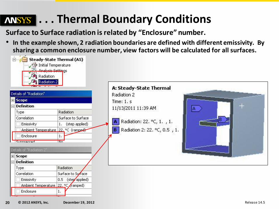
. . . Thermal Boundary Conditions Surface to Surface radiation is related by “Enclosure” number.
• In the example shown, 2 radiation boundaries are defined with different emissivity. By sharing a common enclosure number, view factors will be calculated for all surfaces.
© 2012 ANSYS, Inc. December 19, 2012 21 Release 14.5
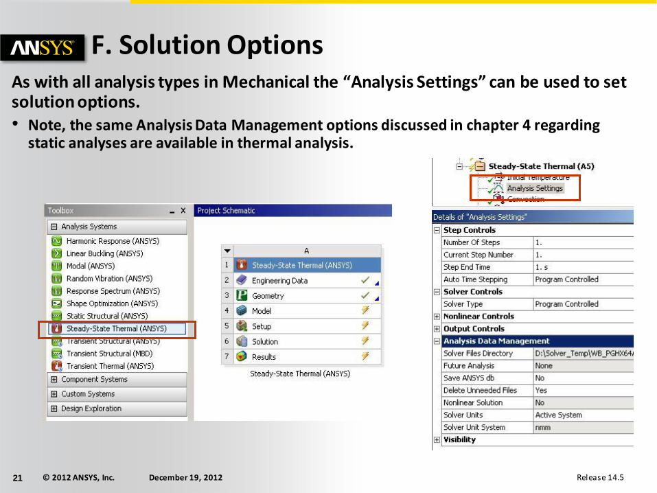
F. Solution Options As with all analysis types in Mechanical the “Analysis Settings” can be used to set solution options. • Note, the same Analysis Data Management options discussed in chapter 4 regarding
static analyses are available in thermal analysis.
© 2012 ANSYS, Inc. December 19, 2012 22 Release 14.5
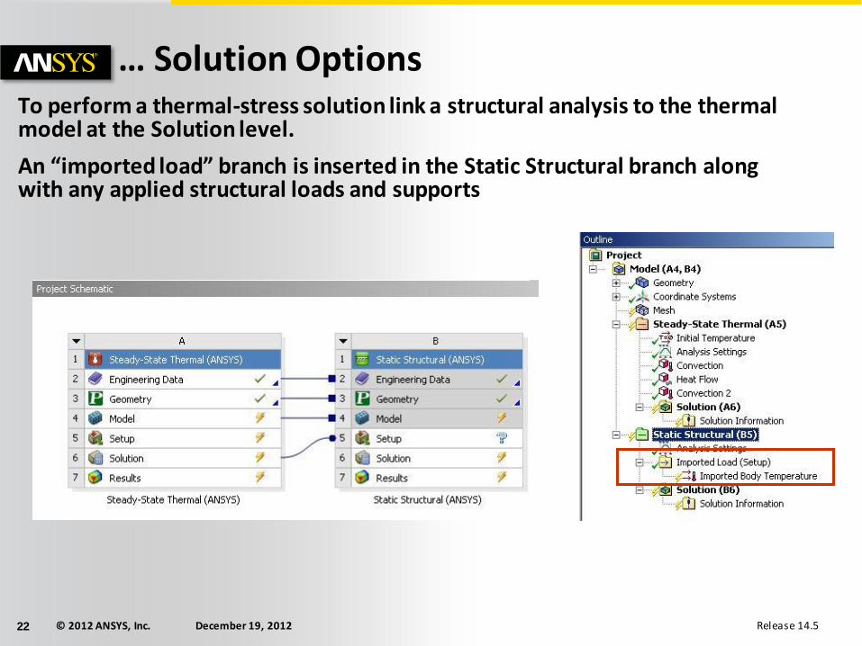
… Solution Options To perform a thermal-stress solution link a structural analysis to the thermal model at the Solution level.
An “imported load” branch is inserted in the Static Structural branch along with any applied structural loads and supports

© 2012 ANSYS, Inc. December 19, 2012 23 Release 14.5
G. Results and Postprocessing Various results are available for postprocessing:
• Temperature
• Heat Flux
• “Reaction” Heat Flow Rate
• User defined results
In Mechanical, results can be requested before or after solving.
• A new solution is not required when retrieving new results from a solved model.
© 2012 ANSYS, Inc. December 19, 2012 24 Release 14.5
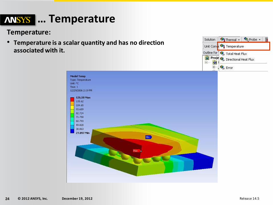
… Temperature Temperature:
• Temperature is a scalar quantity and has no direction associated with it.
© 2012 ANSYS, Inc. December 19, 2012 25 Release 14.5
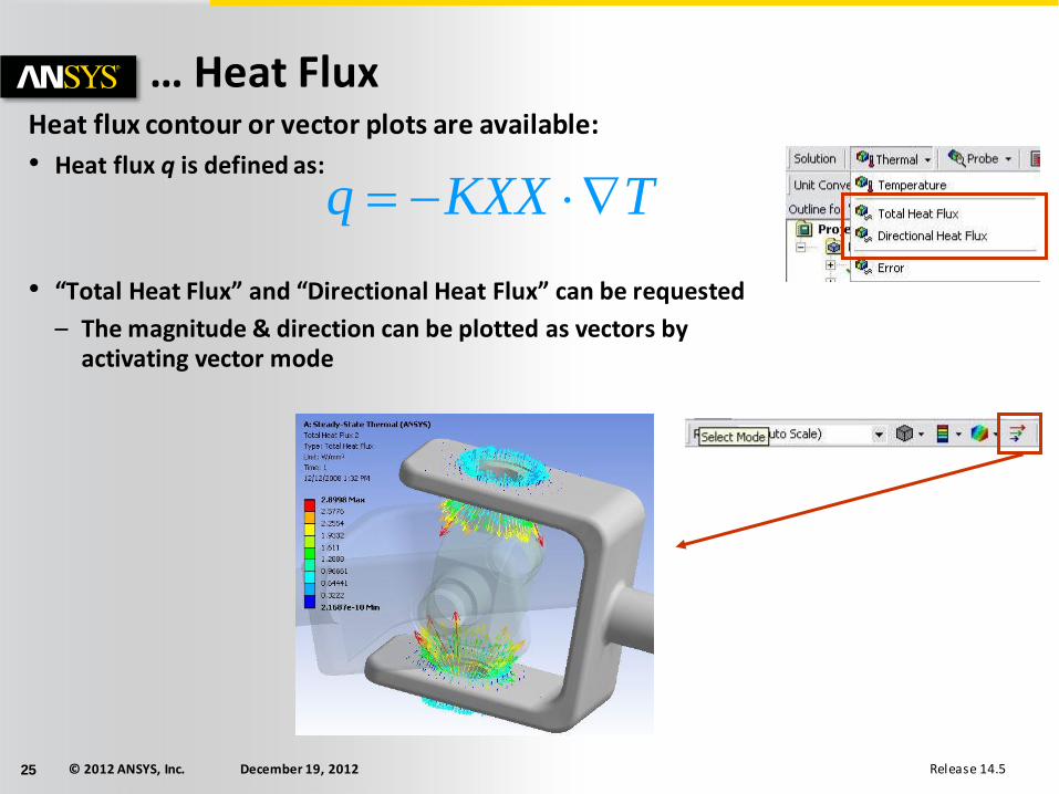
… Heat Flux Heat flux contour or vector plots are available:
• Heat flux q is defined as:
• “Total Heat Flux” and “Directional Heat Flux” can be requested
– The magnitude & direction can be plotted as vectors by activating vector mode
TKXXq
© 2012 ANSYS, Inc. December 19, 2012 26 Release 14.5
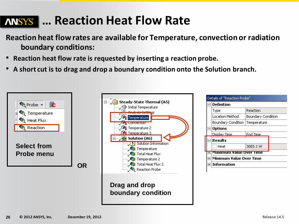
… Reaction Heat Flow Rate Reaction heat flow rates are available for Temperature, convection or radiation
boundary conditions:
• Reaction heat flow rate is requested by inserting a reaction probe.
• A short cut is to drag and drop a boundary condition onto the Solution branch.
OR
Select from
Probe menu
Drag and drop
boundary condition
© 2012 ANSYS, Inc. December 19, 2012 27 Release 14.5
H. Workshop 10.1
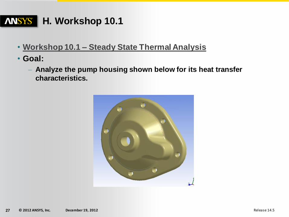
• Workshop 10.1 – Steady State Thermal Analysis
• Goal:
– Analyze the pump housing shown below for its heat transfer
characteristics.