Embed Size (px)
Citation preview
Mechanical Expansion Amplifier © IEEE 2017, Slide 1SAS-2017
JaJames A. Kuzdrallmes A. Kuzdrall
IntrelIntrel Ser Service Companyvice Company
www.intrel.com/mea/www.intrel.com/mea/
Week of 13 March 2017Week of 13 March 2017
MechanicalMechanical
ExpansionExpansion
AmplifierAmplifier
Sensor Applications SymposiumSensor Applications Symposium
Rowan UniversityRowan University
Glassboro, NJGlassboro, NJ
Copyright IEEE 2017Copyright IEEE 2017
1) If it is truly new, you won't be able to say..."It is just like a <something existing> except <some feature that differs>."
Mechanical Expansion Amplifier © IEEE 2017, Slide 2SAS-2017
What is So Different?
� New amplification concept, no semiconductors
� Extremely low noise and very high gain
� Operates at 300ºK with no sensitivity loss
� Highly configurable
� Sensitivities orders of magnitude higher for
radiometers, magnetometers, etc.
� Relatively simple to build.
1) None of the noises associated with semiconductors are found in the metals and insulators comprising the MEA.
2) The range of environmental temperature change might be limited to ±10°C but it can be located over a very wide range of temperatures. The temperature span depends on how much energy is available to keep the gap near its assembly temperature.
3) Configurable using many mechanical, thermal, circuitry, and material options to meet application requirements.
4) Sensitivities beyond any previously known technology.
5) Responsive to many environmental stimuli.
6) All of the materials, parts, and assembly tools are available at costs an individual can afford.
Mechanical Expansion Amplifier © IEEE 2017, Slide 3SAS-2017
Agenda
� The amplification concept
� Gains attainable
� Noise sources and their suppression
� Feedback loop stability
� Photon noise suppression, a physical
breakthrough thought impossible
1) No comment.
Mechanical Expansion Amplifier © IEEE 2017, Slide 4SAS-2017
How Does it Work
� MEA has 3 parts �
� � Gap decreases, strains
increase (�strip= 1.0)� Strain 1: 1.5/27.5= 0.05� Strain 2: 3.6/12= 0.30
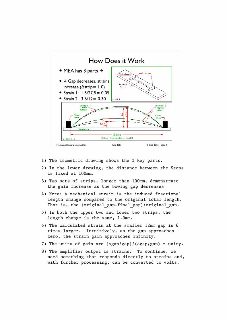
1) The isometric drawing shows the 3 key parts.
2) In the lower drawing, the distance between the Stops is fixed at 100mm.
3) Two sets of strips, longer than 100mm, demonstrate the gain increase as the bowing gap decreases
4) Note: A mechanical strain is the induced fractional length change compared to the original total length. That is, the (original_gap-final_gap)/original_gap.
5) In both the upper two and lower two strips, the length change is the same, 1.0mm.
6) The calculated strain at the smaller 12mm gap is 6 times larger. Intuitively, as the gap approaches zero, the strain gain approaches infinity.
7) The units of gain are (�gap/gap)/(�gap/gap) = unity.
8) The amplifier output is strains. To continue, we need something that responds directly to strains and, with further processing, can be converted to volts.
Mechanical Expansion Amplifier © IEEE 2017, Slide 5SAS-2017
Capacitance and Strain
� C0 = e0*area/gap
� Air-gap capacitor C0 changes by �gap
� �C0 = -(e0*area/gap)*(�gap/gap)
� Capacitance responds to strain rather than �gap
1) An air-gap capacitor is the answer.
2) By grouping the terms of the derivative appropriately, the strain appears as a multiplier of the total capacitance, the gain. The smaller the gap, the larger the gain.
Mechanical Expansion Amplifier © IEEE 2017, Slide 6SAS-2017
Instrument Block Diagram
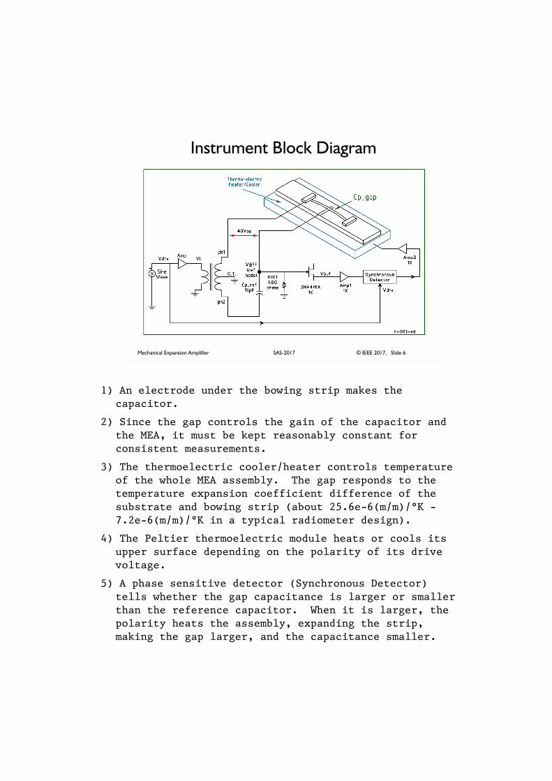
1) An electrode under the bowing strip makes the capacitor.
2) Since the gap controls the gain of the capacitor and the MEA, it must be kept reasonably constant for consistent measurements.
3) The thermoelectric cooler/heater controls temperature of the whole MEA assembly. The gap responds to the temperature expansion coefficient difference of the substrate and bowing strip (about 25.6e-6(m/m)/°K - 7.2e-6(m/m)/°K in a typical radiometer design).
4) The Peltier thermoelectric module heats or cools its upper surface depending on the polarity of its drive voltage.
5) A phase sensitive detector (Synchronous Detector) tells whether the gap capacitance is larger or smaller than the reference capacitor. When it is larger, the polarity heats the assembly, expanding the strip, making the gap larger, and the capacitance smaller.
Mechanical Expansion Amplifier © IEEE 2017, Slide 7SAS-2017
What it Looks Like
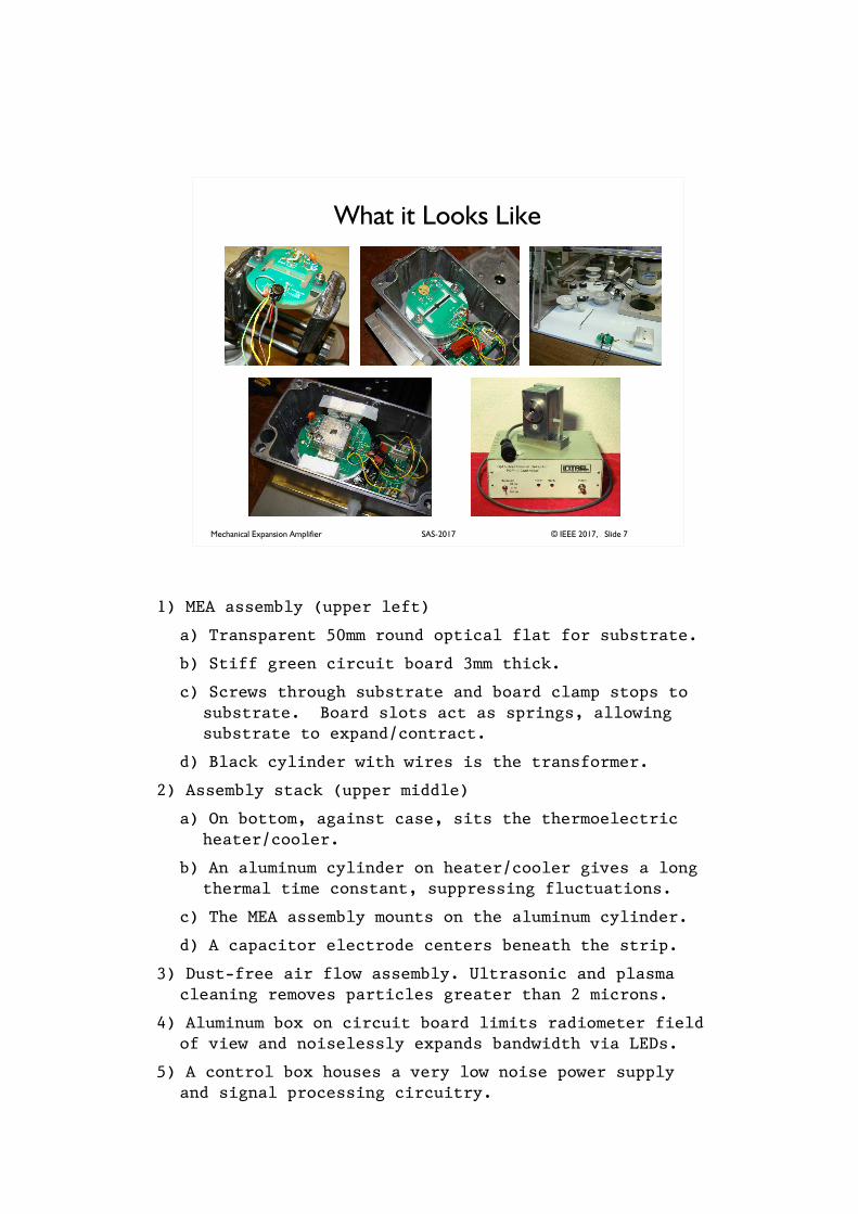
1) MEA assembly (upper left)
a) Transparent 50mm round optical flat for substrate.
b) Stiff green circuit board 3mm thick.
c) Screws through substrate and board clamp stops to substrate. Board slots act as springs, allowing substrate to expand/contract.
d) Black cylinder with wires is the transformer.
2) Assembly stack (upper middle)
a) On bottom, against case, sits the thermoelectric heater/cooler.
b) An aluminum cylinder on heater/cooler gives a long thermal time constant, suppressing fluctuations.
c) The MEA assembly mounts on the aluminum cylinder.
d) A capacitor electrode centers beneath the strip.
3) Dust-free air flow assembly. Ultrasonic and plasma cleaning removes particles greater than 2 microns.
4) Aluminum box on circuit board limits radiometer field of view and noiselessly expands bandwidth via LEDs.
5) A control box houses a very low noise power supply and signal processing circuitry.
Mechanical Expansion Amplifier © IEEE 2017, Slide 8SAS-2017
What Causes Expansion?
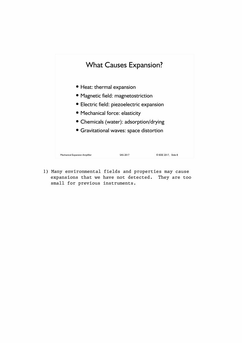
� Heat: thermal expansion
� Magnetic field: magnetostriction
� Electric field: piezoelectric expansion
� Mechanical force: elasticity
� Chemicals (water): adsorption/drying
� Gravitational waves: space distortion
1) Many environmental fields and properties may cause expansions that we have not detected. They are too small for previous instruments.
Mechanical Expansion Amplifier © IEEE 2017, Slide 9SAS-2017
Geometry and Gain
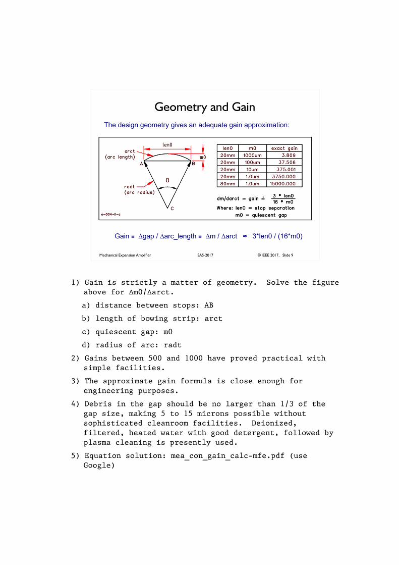
Gain � gap / arc_length � � � �m / arct� � 3*len0 / (16*m0)
The design geometry gives an adequate gain approximation:
1) Gain is strictly a matter of geometry. Solve the figure above for �m0/�arct.
a) distance between stops: AB
b) length of bowing strip: arct
c) quiescent gap: m0
d) radius of arc: radt
2) Gains between 500 and 1000 have proved practical with simple facilities.
3) The approximate gain formula is close enough for engineering purposes.
4) Debris in the gap should be no larger than 1/3 of the gap size, making 5 to 15 microns possible without sophisticated cleanroom facilities. Deionized, filtered, heated water with good detergent, followed by plasma cleaning is presently used.
5) Equation solution: mea_con_gain_calc-mfe.pdf (use Google)
Mechanical Expansion Amplifier © IEEE 2017, Slide 10SAS-2017
Blumlein Bridge Review
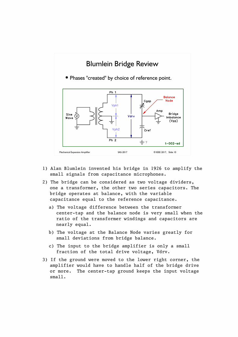
� Phases "created" by choice of reference point.
1) Alan Blumlein invented his bridge in 1926 to amplify the small signals from capacitance microphones.
2) The bridge can be considered as two voltage dividers, one a transformer, the other two series capacitors. The bridge operates at balance, with the variable capacitance equal to the reference capacitance.
a) The voltage difference between the transformer center-tap and the balance node is very small when the ratio of the transformer windings and capacitors are nearly equal.
b) The voltage at the Balance Node varies greatly for small deviations from bridge balance.
c) The input to the bridge amplifier is only a small fraction of the total drive voltage, Vdrv.
3) If the ground were moved to the lower right corner, the amplifier would have to handle half of the bridge drive or more. The center-tap ground keeps the input voltage small.
Mechanical Expansion Amplifier © IEEE 2017, Slide 11SAS-2017
Transduction: Meters to Volts
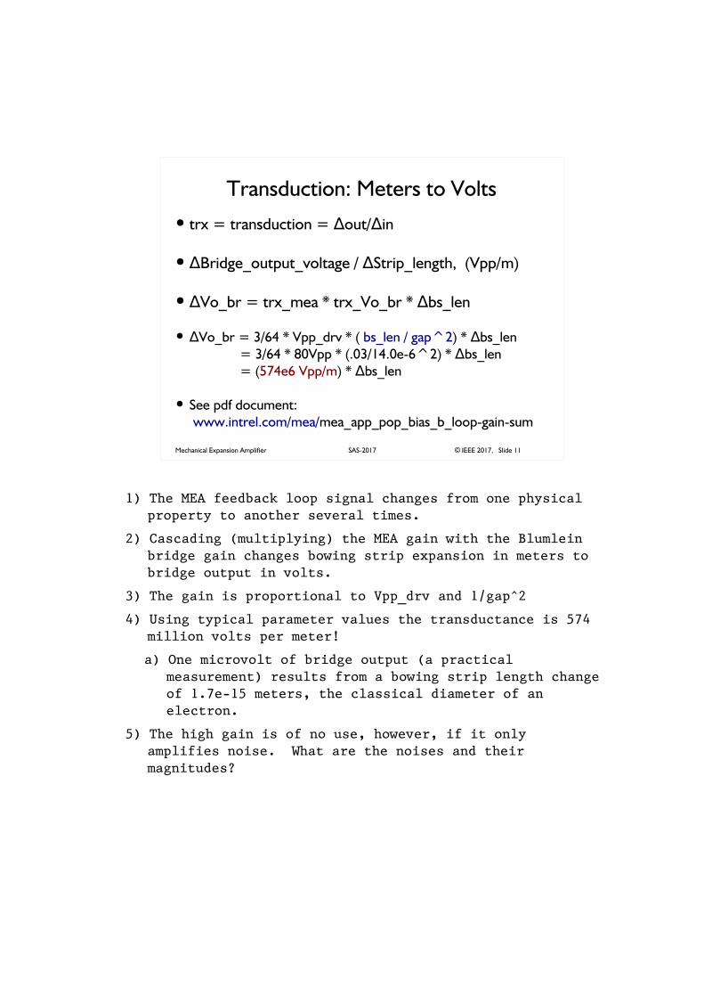
� trx = transduction = out/ in� �
� �Bridge_output_voltage / Strip_length, (Vpp/m)�
� �Vo_br = trx_mea * trx_Vo_br * bs_len�
� �Vo_br = 3/64 * Vpp_drv * ( bs_len / gap^2) * bs_len� = 3/64 * 80Vpp * (.03/14.0e-6^2) * bs_len� = (574e6 Vpp/m) * bs_len�
� See pdf document:
www.intrel.com/mea/mea_app_pop_bias_b_loop-gain-sum
1) The MEA feedback loop signal changes from one physical property to another several times.
2) Cascading (multiplying) the MEA gain with the Blumlein bridge gain changes bowing strip expansion in meters to bridge output in volts.
3) The gain is proportional to Vpp_drv and 1/gap^2
4) Using typical parameter values the transductance is 574 million volts per meter!
a) One microvolt of bridge output (a practical measurement) results from a bowing strip length change of 1.7e-15 meters, the classical diameter of an electron.
5) The high gain is of no use, however, if it only amplifies noise. What are the noises and their magnitudes?
Mechanical Expansion Amplifier © IEEE 2017, Slide 12SAS-2017
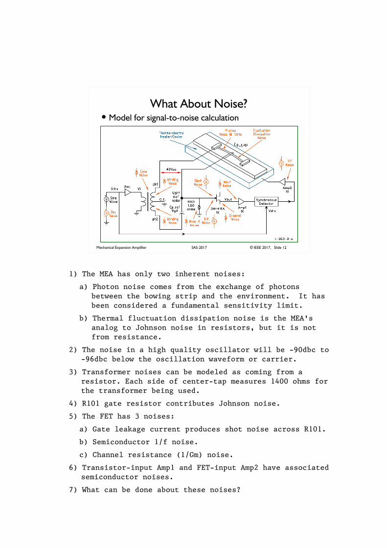
What About Noise?� Model for signal-to-noise calculation
1) The MEA has only two inherent noises:
a) Photon noise comes from the exchange of photons between the bowing strip and the environment. It has been considered a fundamental sensitivity limit.
b) Thermal fluctuation dissipation noise is the MEA's analog to Johnson noise in resistors, but it is not from resistance.
2) The noise in a high quality oscillator will be -90dbc to -96dbc below the oscillation waveform or carrier.
3) Transformer noises can be modeled as coming from a resistor. Each side of center-tap measures 1400 ohms for the transformer being used.
4) R101 gate resistor contributes Johnson noise.
5) The FET has 3 noises:
a) Gate leakage current produces shot noise across R101.
b) Semiconductor 1/f noise.
c) Channel resistance (1/Gm) noise.
6) Transistor-input Amp1 and FET-input Amp2 have associated semiconductor noises.
7) What can be done about these noises?
Mechanical Expansion Amplifier © IEEE 2017, Slide 13SAS-2017
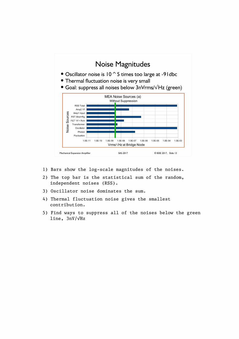
Noise Magnitudes� Oscillator noise is 10^5 times too large at -91dbc� Thermal fluctuation noise is very small� Goal: suppress all noises below 3nVrms/�Hz (green)
1) Bars show the log-scale magnitudes of the noises.
2) The top bar is the statistical sum of the random, independent noises (RSS).
3) Oscillator noise dominates the sum.
4) Thermal fluctuation noise gives the smallest contribution.
5) Find ways to suppress all of the noises below the green line, 3nV/�Hz
Mechanical Expansion Amplifier © IEEE 2017, Slide 14SAS-2017
Bridge Frequency
� FET1/f noise at negligible at 30KHz
� 30KHz reduces bridge source impedance,
shunting gate shot and bias resistor noise
1) Blumlein bridge drive in the range of 10KHz to 200KHz has advantages:
a) Semiconductor 1/f noise has diminished.
b) Low capacitive reactance shunts R101 and shot noise to insignificance.
c) Small, efficient, but expensive transformers are available. Low frequency (less than 1000Hz) response is eliminated to make them small. Audio transformers exhibit excessive saturation and phase shift above 20KHz.
Mechanical Expansion Amplifier © IEEE 2017, Slide 15SAS-2017
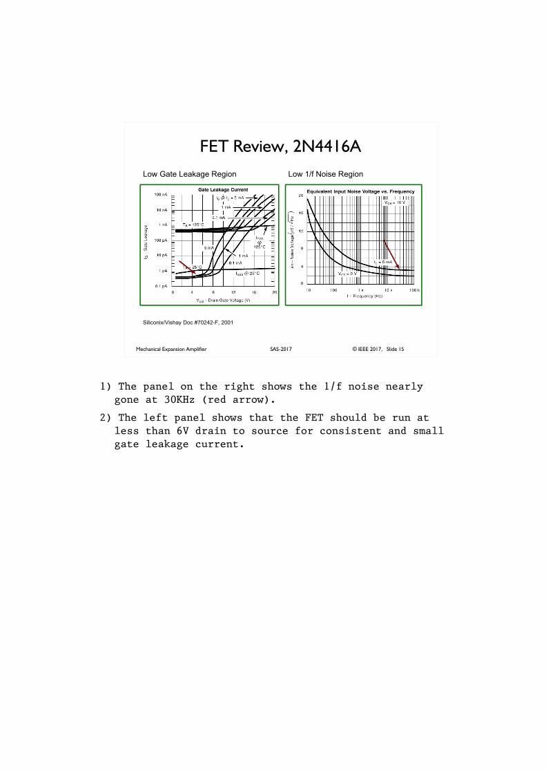
FET Review, 2N4416A
Siliconix/Vishay Doc #70242-F, 2001
Low Gate Leakage Region Low 1/f Noise Region
1) The panel on the right shows the 1/f noise nearly gone at 30KHz (red arrow).
2) The left panel shows that the FET should be run at less than 6V drain to source for consistent and small gate leakage current.
Mechanical Expansion Amplifier © IEEE 2017, Slide 16SAS-2017
Gain Accuracy
� Gap size determines MEA gain
� 1% gain accuracy
� Loop with 100X negative feedback� feedback matches Cgap to Cref by subtracting
99% of phase1 from phase2� 100X gives MEA 1% gain accuracy (gap precision)� feedback also subtracts bridge drive noise to 1
part in 100
1) Subtracting Phase 1 from Phase 2 brings the bridge into closer balance.
a) Subtraction means the strain sensitivity is the same at balance as it is anywhere near balance.
b) Everything coming from the transformer subtracts to a fraction of its original self: bridge drive voltage, oscillator noise, transformer resistance noise.
Mechanical Expansion Amplifier © IEEE 2017, Slide 17SAS-2017
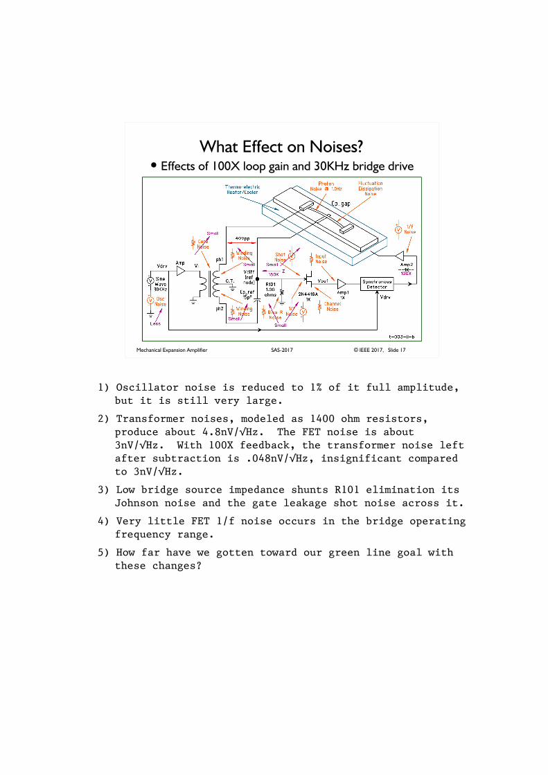
What Effect on Noises?� Effects of 100X loop gain and 30KHz bridge drive
1) Oscillator noise is reduced to 1% of it full amplitude, but it is still very large.
2) Transformer noises, modeled as 1400 ohm resistors, produce about 4.8nV/�Hz. The FET noise is about 3nV/�Hz. With 100X feedback, the transformer noise left after subtraction is .048nV/�Hz, insignificant compared to 3nV/�Hz.
3) Low bridge source impedance shunts R101 elimination its Johnson noise and the gate leakage shot noise across it.
4) Very little FET 1/f noise occurs in the bridge operating frequency range.
5) How far have we gotten toward our green line goal with these changes?
Mechanical Expansion Amplifier © IEEE 2017, Slide 18SAS-2017
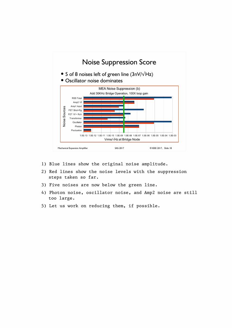
Noise Suppression Score
� 5 of 8 noises left of green line (3nV/�Hz)� Oscillator noise dominates
1) Blue lines show the original noise amplitude.
2) Red lines show the noise levels with the suppression steps taken so far.
3) Five noises are now below the green line.
4) Photon noise, oscillator noise, and Amp2 noise are still too large.
5) Let us work on reducing them, if possible.
Mechanical Expansion Amplifier © IEEE 2017, Slide 19SAS-2017
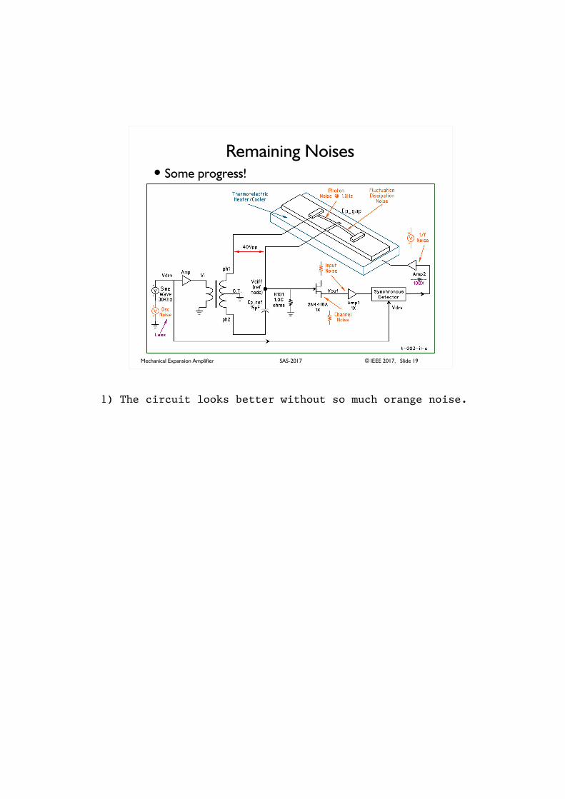
Remaining Noises� Some progress!
1) The circuit looks better without so much orange noise.
Mechanical Expansion Amplifier © IEEE 2017, Slide 20SAS-2017
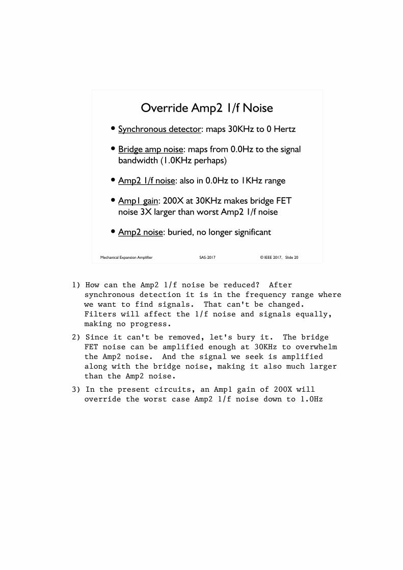
Override Amp2 1/f Noise
� Synchronous detector: maps 30KHz to 0 Hertz
� Bridge amp noise: maps from 0.0Hz to the signal
bandwidth (1.0KHz perhaps)
� Amp2 1/f noise: also in 0.0Hz to 1KHz range
� Amp1 gain: 200X at 30KHz makes bridge FET
noise 3X larger than worst Amp2 1/f noise
� Amp2 noise: buried, no longer significant
1) How can the Amp2 1/f noise be reduced? After synchronous detection it is in the frequency range where we want to find signals. That can't be changed. Filters will affect the 1/f noise and signals equally, making no progress.
2) Since it can't be removed, let's bury it. The bridge FET noise can be amplified enough at 30KHz to overwhelm the Amp2 noise. And the signal we seek is amplified along with the bridge noise, making it also much larger than the Amp2 noise.
3) In the present circuits, an Amp1 gain of 200X will override the worst case Amp2 1/f noise down to 1.0Hz
Mechanical Expansion Amplifier © IEEE 2017, Slide 21SAS-2017
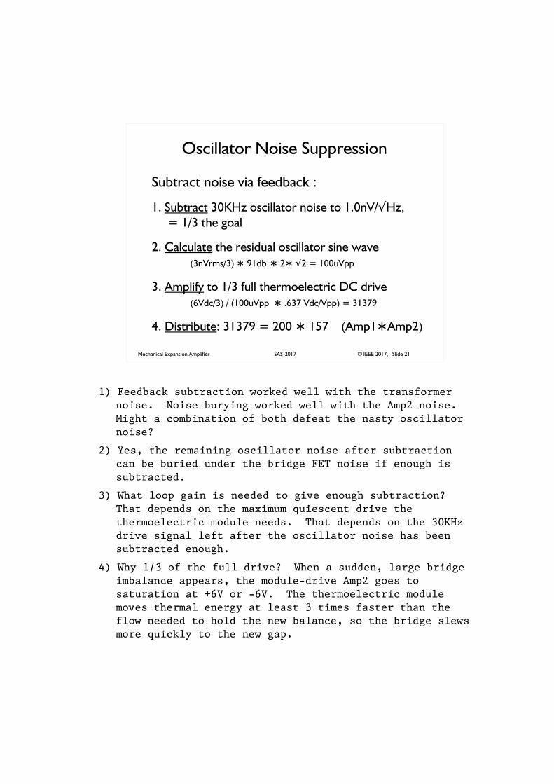
Oscillator Noise Suppression
Subtract noise via feedback :
1. Subtract 30KHz oscillator noise to 1.0nV/�Hz,
= 1/3 the goal
2. Calculate the residual oscillator sine wave
(3nVrms/3) � 91db � 2� �2 = 100uVpp
3. Amplify to 1/3 full thermoelectric DC drive
(6Vdc/3) / (100uVpp � .637 Vdc/Vpp) = 31379
4. Distribute: 31379 = 200 � 157 (Amp1�Amp2)
1) Feedback subtraction worked well with the transformer noise. Noise burying worked well with the Amp2 noise. Might a combination of both defeat the nasty oscillator noise?
2) Yes, the remaining oscillator noise after subtraction can be buried under the bridge FET noise if enough is subtracted.
3) What loop gain is needed to give enough subtraction? That depends on the maximum quiescent drive the thermoelectric module needs. That depends on the 30KHz drive signal left after the oscillator noise has been subtracted enough.
4) Why 1/3 of the full drive? When a sudden, large bridge imbalance appears, the module-drive Amp2 goes to saturation at +6V or -6V. The thermoelectric module moves thermal energy at least 3 times faster than the flow needed to hold the new balance, so the bridge slews more quickly to the new gap.
Mechanical Expansion Amplifier © IEEE 2017, Slide 22SAS-2017
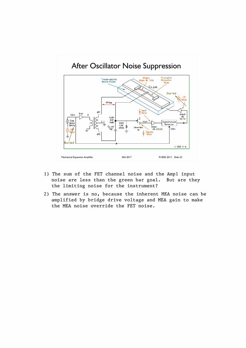
After Oscillator Noise Suppression
1) The sum of the FET channel noise and the Amp1 input noise are less than the green bar goal. But are they the limiting noise for the instrument?
2) The answer is no, because the inherent MEA noise can be amplified by bridge drive voltage and MEA gain to make the MEA noise override the FET noise.
Mechanical Expansion Amplifier © IEEE 2017, Slide 23SAS-2017
Almost There!
Only photon noise exceeds the goal.
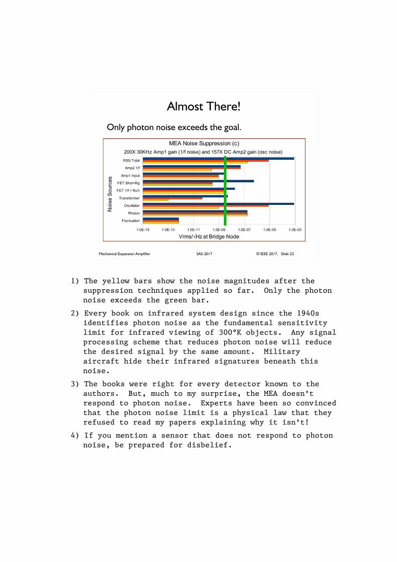
1) The yellow bars show the noise magnitudes after the suppression techniques applied so far. Only the photon noise exceeds the green bar.
2) Every book on infrared system design since the 1940s identifies photon noise as the fundamental sensitivity limit for infrared viewing of 300°K objects. Any signal processing scheme that reduces photon noise will reduce the desired signal by the same amount. Military aircraft hide their infrared signatures beneath this noise.
3) The books were right for every detector known to the authors. But, much to my surprise, the MEA doesn't respond to photon noise. Experts have been so convinced that the photon noise limit is a physical law that they refused to read my papers explaining why it isn't!
4) If you mention a sensor that does not respond to photon noise, be prepared for disbelief.
Mechanical Expansion Amplifier © IEEE 2017, Slide 24SAS-2017
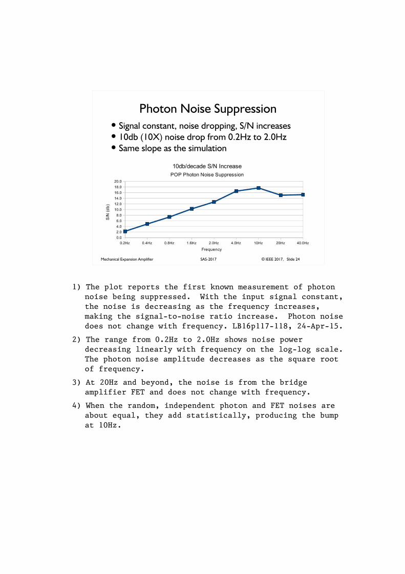
Photon Noise Suppression� Signal constant, noise dropping, S/N increases� 10db (10X) noise drop from 0.2Hz to 2.0Hz� Same slope as the simulation
1) The plot reports the first known measurement of photon noise being suppressed. With the input signal constant, the noise is decreasing as the frequency increases, making the signal-to-noise ratio increase. Photon noise does not change with frequency. LB16p117-118, 24-Apr-15.
2) The range from 0.2Hz to 2.0Hz shows noise power decreasing linearly with frequency on the log-log scale. The photon noise amplitude decreases as the square root of frequency.
3) At 20Hz and beyond, the noise is from the bridge amplifier FET and does not change with frequency.
4) When the random, independent photon and FET noises are about equal, they add statistically, producing the bump at 10Hz.
Mechanical Expansion Amplifier © IEEE 2017, Slide 25SAS-2017
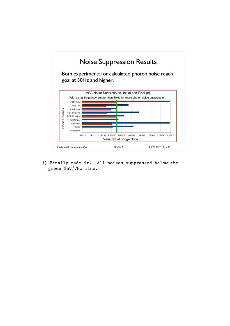
Noise Suppression Results
Both experimental or calculated photon noise reach
goal at 30Hz and higher.
1) Finally made it. All noises suppressed below the green 3nV/�Hz line.
Mechanical Expansion Amplifier © IEEE 2017, Slide 26SAS-2017
Noise Suppression Recapitulation
� 1/f noise of Blumlein bridge amp FET is lowest
for 20KHz to 100KHz operation
� Shot and resistor noise at bridge amp gate is
shunted by low bridge impedance
� Transformer noise is small and subtracted
� Post-detection 1/f noise overridden by bridge
amp noise amplified at the bridge frequency
� Oscillator noise subtracted-out by gap control
feedback loop gain
� Photon noise suppressed by MEA thermal
diffusion time constant
1) The techniques used for noise reduction in the MEA should be kept in mind for use in other applications.
Mechanical Expansion Amplifier © IEEE 2017, Slide 27SAS-2017
Yipes! No Signal Gain
� 120.0e+6 feedback gain suppresses oscillator noise� Gain from Table 2 mea_app_pop_bias_c_phase-adj-sum.pdf
� Also suppresses MEA signal below FET noise
� What can distinguish signal from drift and noise?
� Frequency. Signals occur above 1.0 Hertz
� No feedback above 1.0Hz
1) The large negative feedback needed to suppress the oscillator noise does not discriminate environmental change from signal. Signals are suppressed along with anything else that changes the gap.
2) Use frequency to differentiate signal from noise.
3) The large feedback loop gain must be reduced to less than one above the lowest signal frequency.
4) A simple resistance-capacitance time constant, such as used in the opamps, will not work because a thermal pole from the aluminum cylinder under the MEA appears at about 0.001Hz adding its 90 degrees of phase shift.
5) Lag networks with carefully chosen pole and zero locations can accomplish the job, however.
Mechanical Expansion Amplifier © IEEE 2017, Slide 28SAS-2017
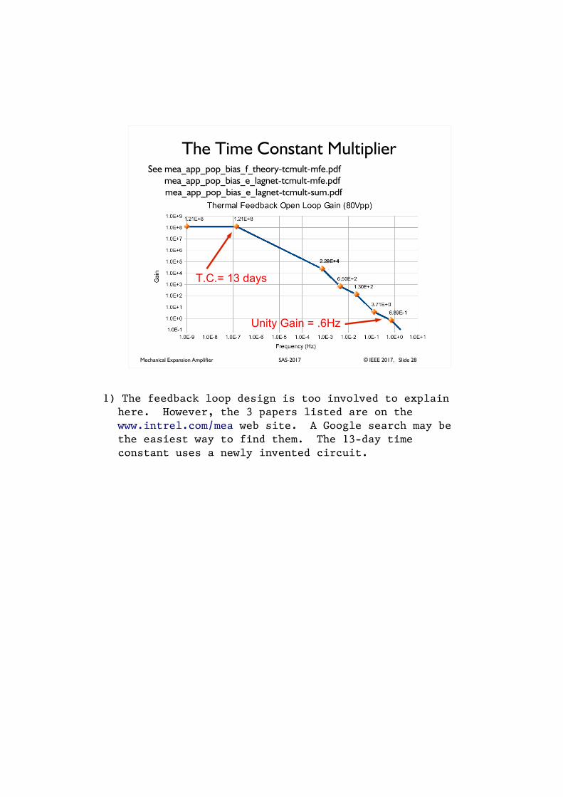
The Time Constant MultiplierSee mea_app_pop_bias_f_theory-tcmult-mfe.pdf
mea_app_pop_bias_e_lagnet-tcmult-mfe.pdf
mea_app_pop_bias_e_lagnet-tcmult-sum.pdf
T.C.= 13 days
Unity Gain = .6Hz
1) The feedback loop design is too involved to explain here. However, the 3 papers listed are on the www.intrel.com/mea web site. A Google search may be the easiest way to find them. The 13-day time constant uses a newly invented circuit.
Mechanical Expansion Amplifier © IEEE 2017, Slide 29SAS-2017
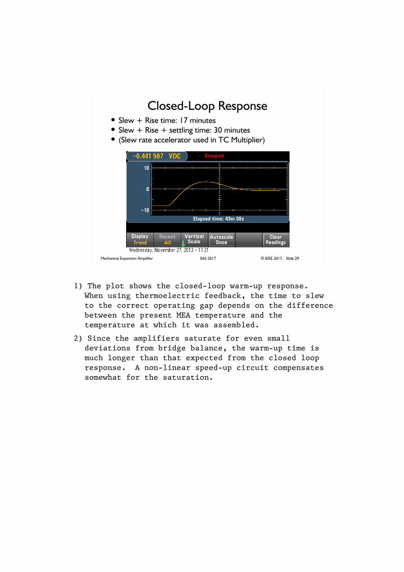
Closed-Loop Response� Slew + Rise time: 17 minutes� Slew + Rise + settling time: 30 minutes� (Slew rate accelerator used in TC Multiplier)
1) The plot shows the closed-loop warm-up response. When using thermoelectric feedback, the time to slew to the correct operating gap depends on the difference between the present MEA temperature and the temperature at which it was assembled.
2) Since the amplifiers saturate for even small deviations from bridge balance, the warm-up time is much longer than that expected from the closed loop response. A non-linear speed-up circuit compensates somewhat for the saturation.
Mechanical Expansion Amplifier © IEEE 2017, Slide 30SAS-2017
Photon Noise
1) Why doesn't this amplifier produce noise as photons randomly hit it? All other radiometers and sensitive instruments have a sensitivity-limiting photon noise.
Mechanical Expansion Amplifier © IEEE 2017, Slide 31SAS-2017
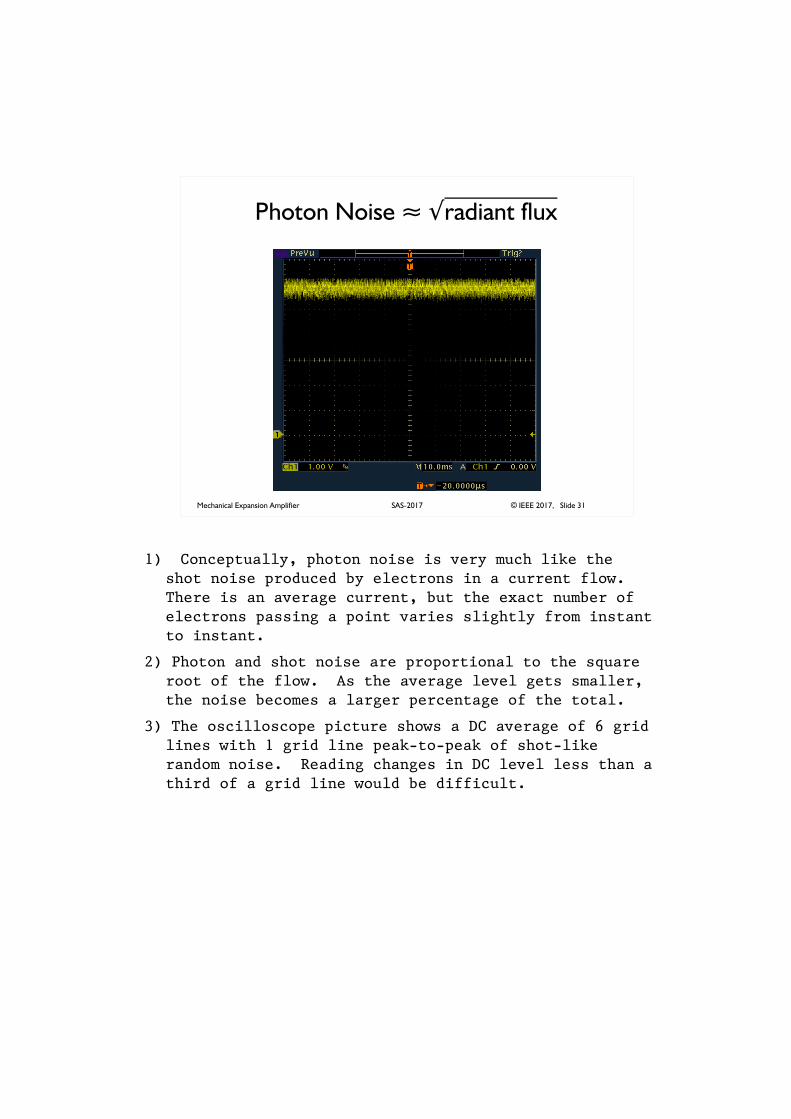
Photon Noise � �radiant flux
1) Conceptually, photon noise is very much like the shot noise produced by electrons in a current flow. There is an average current, but the exact number of electrons passing a point varies slightly from instant to instant.
2) Photon and shot noise are proportional to the square root of the flow. As the average level gets smaller, the noise becomes a larger percentage of the total.
3) The oscilloscope picture shows a DC average of 6 grid lines with 1 grid line peak-to-peak of shot-like random noise. Reading changes in DC level less than a third of a grid line would be difficult.
Mechanical Expansion Amplifier © IEEE 2017, Slide 32SAS-2017
Photon Noise Suppression
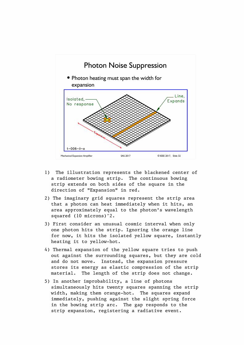
� Photon heating must span the width for
expansion
�
1) The illustration represents the blackened center of a radiometer bowing strip. The continuous bowing strip extends on both sides of the square in the direction of "Expansion" in red.
2) The imaginary grid squares represent the strip area that a photon can heat immediately when it hits, an area approximately equal to the photon's wavelength squared (10 microns)^2.
3) First consider an unusual cosmic interval when only one photon hits the strip. Ignoring the orange line for now, it hits the isolated yellow square, instantly heating it to yellow-hot.
4) Thermal expansion of the yellow square tries to push out against the surrounding squares, but they are cold and do not move. Instead, the expansion pressure stores its energy as elastic compression of the strip material. The length of the strip does not change.
5) In another improbability, a line of photons simultaneously hits twenty squares spanning the strip width, making them orange-hot. The squares expand immediately, pushing against the slight spring force in the bowing strip arc. The gap responds to the strip expansion, registering a radiative event.
Mechanical Expansion Amplifier © IEEE 2017, Slide 33SAS-2017
Photon Noise Suppression
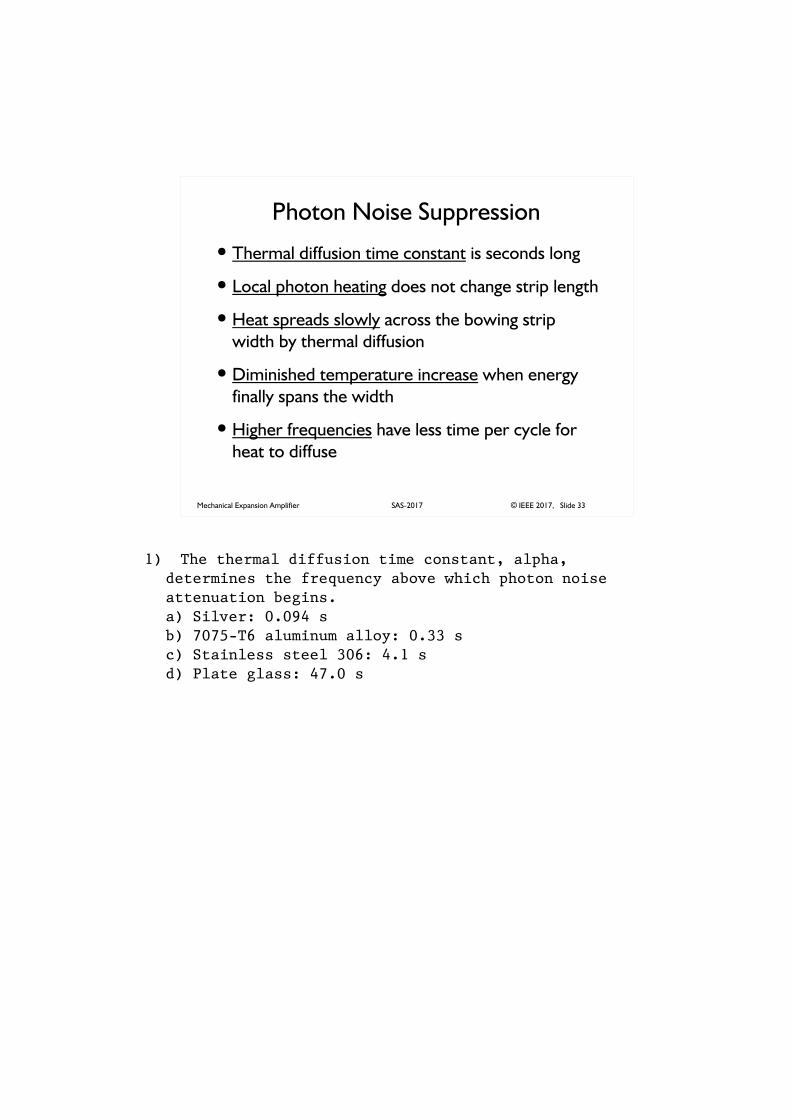
� Thermal diffusion time constant is seconds long
� Local photon heating does not change strip length
� Heat spreads slowly across the bowing strip
width by thermal diffusion
� Diminished temperature increase when energy
finally spans the width
� Higher frequencies have less time per cycle for
heat to diffuse
1) The thermal diffusion time constant, alpha, determines the frequency above which photon noise attenuation begins.a) Silver: 0.094 sb) 7075-T6 aluminum alloy: 0.33 sc) Stainless steel 306: 4.1 sd) Plate glass: 47.0 s
Mechanical Expansion Amplifier © IEEE 2017, Slide 34SAS-2017
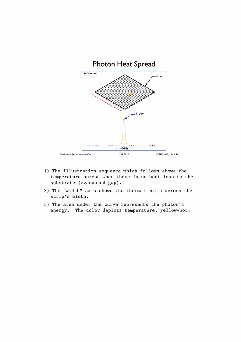
Photon Heat Spread
1) The illustration sequence which follows shows the temperature spread when there is no heat loss to the substrate (evacuated gap).
2) The "width" axis shows the thermal cells across the strip's width.
3) The area under the curve represents the photon's energy. The color depicts temperature, yellow-hot.
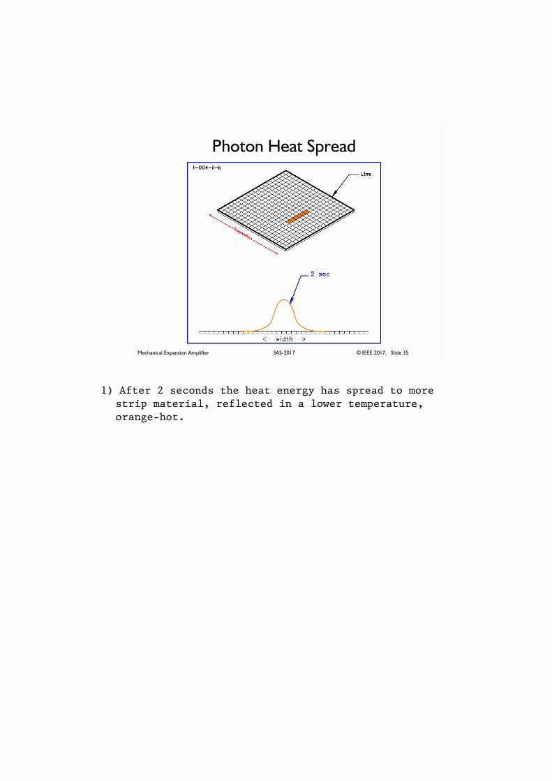
Mechanical Expansion Amplifier © IEEE 2017, Slide 35SAS-2017
Photon Heat Spread
1) After 2 seconds the heat energy has spread to more strip material, reflected in a lower temperature, orange-hot.
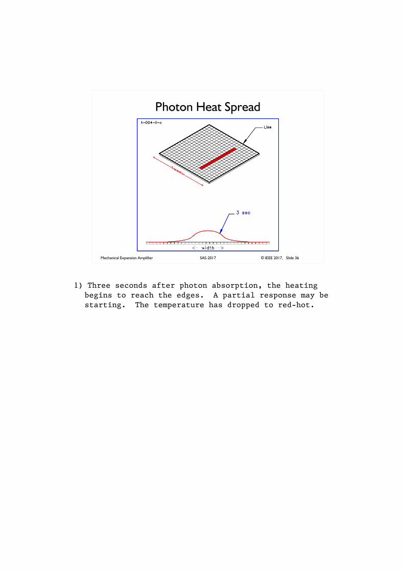
Mechanical Expansion Amplifier © IEEE 2017, Slide 36SAS-2017
Photon Heat Spread
1) Three seconds after photon absorption, the heating begins to reach the edges. A partial response may be starting. The temperature has dropped to red-hot.
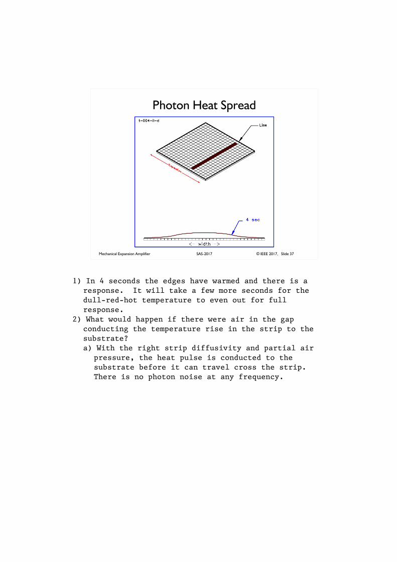
Mechanical Expansion Amplifier © IEEE 2017, Slide 37SAS-2017
Photon Heat Spread
1) In 4 seconds the edges have warmed and there is a response. It will take a few more seconds for the dull-red-hot temperature to even out for full response.
2) What would happen if there were air in the gap conducting the temperature rise in the strip to the substrate?a) With the right strip diffusivity and partial air
pressure, the heat pulse is conducted to the substrate before it can travel cross the strip. There is no photon noise at any frequency.
Mechanical Expansion Amplifier © IEEE 2017, Slide 38SAS-2017
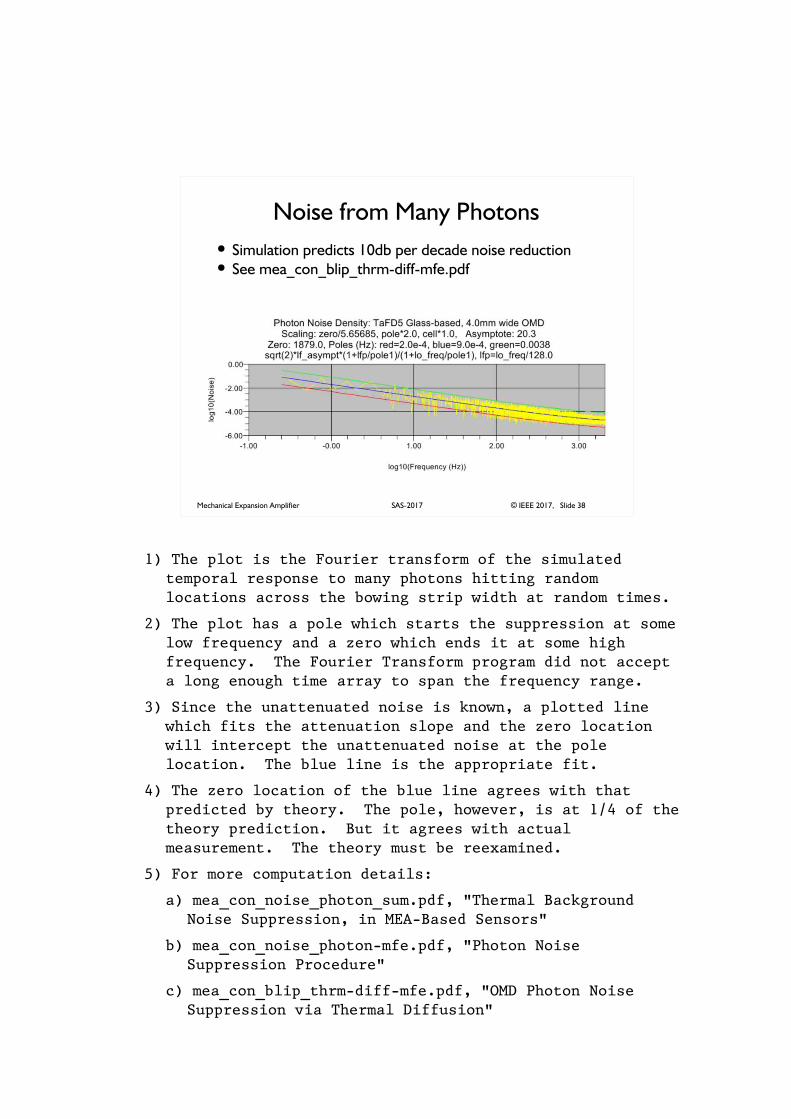
Noise from Many Photons
� Simulation predicts 10db per decade noise reduction� See mea_con_blip_thrm-diff-mfe.pdf
1) The plot is the Fourier transform of the simulated temporal response to many photons hitting random locations across the bowing strip width at random times.
2) The plot has a pole which starts the suppression at some low frequency and a zero which ends it at some high frequency. The Fourier Transform program did not accept a long enough time array to span the frequency range.
3) Since the unattenuated noise is known, a plotted line which fits the attenuation slope and the zero location will intercept the unattenuated noise at the pole location. The blue line is the appropriate fit.
4) The zero location of the blue line agrees with that predicted by theory. The pole, however, is at 1/4 of the theory prediction. But it agrees with actual measurement. The theory must be reexamined.
5) For more computation details:
a) mea_con_noise_photon_sum.pdf, "Thermal Background Noise Suppression, in MEA-Based Sensors"
b) mea_con_noise_photon-mfe.pdf, "Photon Noise Suppression Procedure"
c) mea_con_blip_thrm-diff-mfe.pdf, "OMD Photon Noise Suppression via Thermal Diffusion"
Mechanical Expansion Amplifier © IEEE 2017, Slide 39SAS-2017
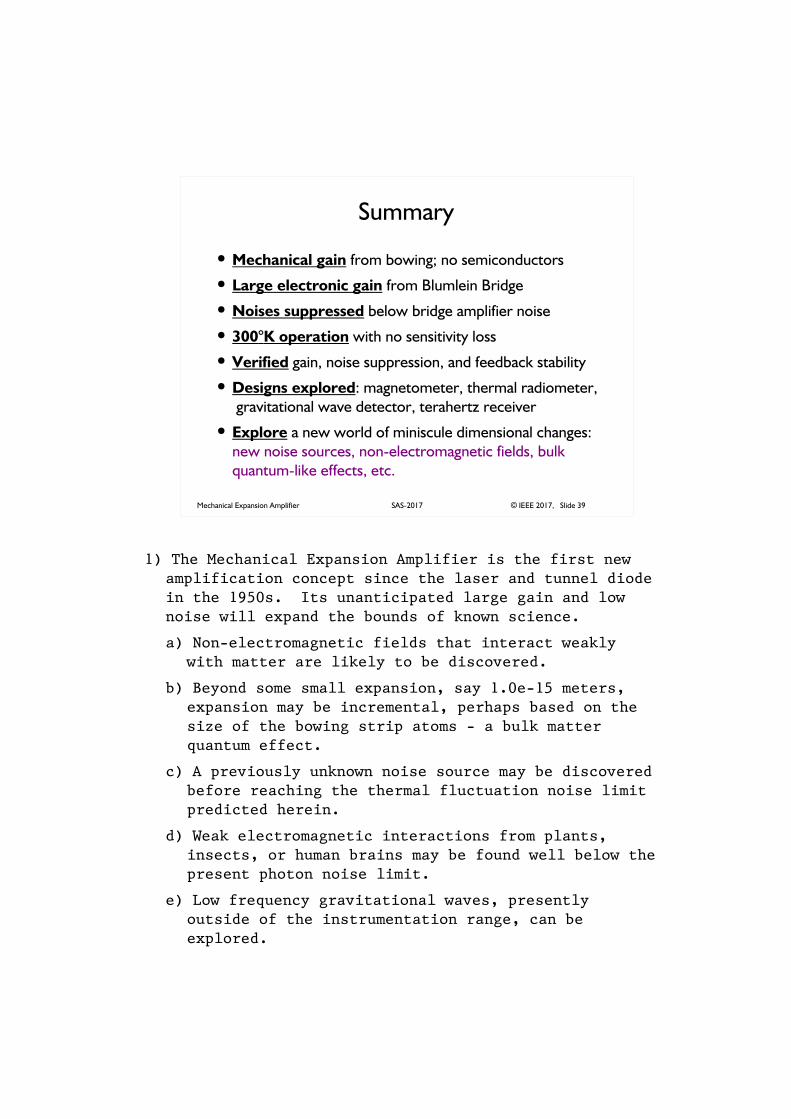
Summary
� Mechanical gain from bowing; no semiconductors
� Large electronic gain from Blumlein Bridge
� Noises suppressed below bridge amplifier noise
� 300°K operation with no sensitivity loss
� Verified gain, noise suppression, and feedback stability
� Designs explored: magnetometer, thermal radiometer,
gravitational wave detector, terahertz receiver
� Explore a new world of miniscule dimensional changes:
new noise sources, non-electromagnetic fields, bulk
quantum-like effects, etc.
1) The Mechanical Expansion Amplifier is the first new amplification concept since the laser and tunnel diode in the 1950s. Its unanticipated large gain and low noise will expand the bounds of known science.
a) Non-electromagnetic fields that interact weakly with matter are likely to be discovered.
b) Beyond some small expansion, say 1.0e-15 meters, expansion may be incremental, perhaps based on the size of the bowing strip atoms - a bulk matter quantum effect.
c) A previously unknown noise source may be discovered before reaching the thermal fluctuation noise limit predicted herein.
d) Weak electromagnetic interactions from plants, insects, or human brains may be found well below the present photon noise limit.
e) Low frequency gravitational waves, presently outside of the instrumentation range, can be explored.
Mechanical Expansion Amplifier © IEEE 2017, Slide 40SAS-2017
Thank you for attending.
Best wishes for asuccessful career.James A. Kuzdrall