Embed Size (px)
Citation preview

PE Mechanical – TFS – Thermodynamics & Energy Balances Study Problems www.SlaythePE.com
MECHANICAL ENGINEERING
THERMAL AND FLUID SYSTEMS
STUDY PROBLEMS
PRINCIPLES:
THERMODYNAMICS & ENERGY BALANCES
www.SlaythePE.com 1 Copyright © 2018. All rights reserved.

PE Mechanical – TFS – Thermodynamics & Energy Balances Study Problems www.SlaythePE.com
How to use this book
The exam specifications in effect since April 2017 state that approximately 6 problems from the
“Thermodynamics” topic will be in the morning “Principles” portion of your exam. The problems in
this book will prepare you for all the thermodynamics problems in the morning “Principles” portion.
Furthermore, a solid understanding of this topic is required to have any success with the 24 questions in
the afternoon “Energy/Power System Applications” portion. The problems in this book will prepare
you for the thermodynamics problems of the afternoon “Energy/Power System Applications” portion of
the exam.
How it works
This study problems book works on what we call the “principle of progressive overload”. With this
technique you start with very easy problems and smoothly progress towards more complex problems.
A good example of progressive overload is the story of the famous wrestler Milo of Croton in ancient
Greece. This extraordinarily strong man was allegedly capable of carrying a fully grown bull on his
shoulders. He was reported to have achieved this tremendous strength by walking around town with a
new born calf on his shoulders every single day. As the calf grew, so did the man's strength.
We recommend you work the problems in this book in the order they are presented. Within each
section of the book, the first problems will feel “light”, like carrying that baby calf – you might even be
tempted to skip them. We strongly urge you to resist this temptation. As you progress, the problems
become harder, but the work you've been putting in with all the previous problems will bear fruit. You
will be pleasantly surprised at how relatively easy those “hard” problems will seem. You will soon be
carrying intellectual bulls on your shoulders! The problems that are considered “exam-level
difficult” are denoted with an asterisk.
www.SlaythePE.com 2 Copyright © 2018. All rights reserved.

PE Mechanical – TFS – Thermodynamics & Energy Balances Study Problems www.SlaythePE.com
This book is comprised of the following sections:
Sections Page
01: Mass & Volume Flow Rates 5
02: Mass Balances 7
03: Introduction to Energy Balances 11
04: Control Volume Analysis – Incompressible Liquids 19
05: Control Volume Analysis – Ideal Gases 23
06: Control Volume Analysis – Saturated Mixtures & Superheated Vapors 29
07: Entropy Balance, Isentropic Processes & Isentropic Efficiencies 41
08: The Carnot Cycle (Heat Engines, Heat Pumps & Refrigerators) 51
09: Rankine Cycle 59
10: Brayton Cycle 67
11: Vapor Compression Refrigeration Cycle 75
12: Otto and Diesel Cycles 81
13: Gas Mixtures 89
14: Combustion 95
15: Answers 103
For the most part, these sections are not independent (specially the first seven) and build from the
previous ones. We recommend you go through them in the order presented, and be sure to review them
all. Each section begins with a brief discussion of the relevant concepts and equations. These
discussions are laser-focused on the aspects that are relevant to the P.E. exam and do not go into
derivations with academic rigor.
www.SlaythePE.com 3 Copyright © 2018. All rights reserved.

PE Mechanical – TFS – Thermodynamics & Energy Balances Study Problems www.SlaythePE.com
This page was intentionally left blank
www.SlaythePE.com 4 Copyright © 2018. All rights reserved.

PE Mechanical – TFS – Thermodynamics & Energy Balances Study Problems www.SlaythePE.com
SECTION 01: Mass and Volume Flow Rates
The key equation for this section is the relationship between mass flow rate, m , volume flow rate, V ,
and average flow velocity, V . This relationship takes on many forms, but they are all really the same:
m=ρ AV (1-1)
Since:
V =A V (1-2)
where A is the pipe or duct cross-sectional area, we also have the alternate forms of equation (1-1):
m=ρ V , m=V /v , and m=AV / v , where ρ is density, and v=1/ ρ is the specific volume.
PROBLEMS
01-01. Water ( ρ =62.4 lbm /ft3 ) flows at a rate of 300 gpm in a 4-inch, schedule-40, seamless steel
pipe (ID=4.026 inches). What is the average flow velocity, in feet per minute (fpm)?
01-02. Water ( ρ =62.4 lbm /ft3 ) flows at a rate of 300 gpm in a 4-inch, schedule-40, seamless steel
pipe (ID=4.026 inches). What is the mass flow rate, in pound-mass per hour (lbm/h)?
01-03. Steam with a specific volume of v=5ft3/ lbm flows at a velocity of 500 ft/s within a 4-inch,
schedule-40, seamless steel pipe (ID=4.026 inches). What is the mass flow rate in lbm/h?
01-04. What is the volumetric flow rate of steam – in cubic feet per minute – for the previous problem?
01-05. Air flows in a circular cross section duct with a volumetric flow rate of 3,000 CFM (cubic feet
per minute) and a flow velocity of 2,200 feet per minute. What is the duct diameter, in inches?
01-06. Which has a higher flow velocity in a 3-in ID pipe: 300 gpm of water, or 300 lbm/h of steam
with v=7ft 3/ lbm ?
www.SlaythePE.com 5 Copyright © 2018. All rights reserved.

PE Mechanical – TFS – Thermodynamics & Energy Balances Study Problems www.SlaythePE.com
This page was intentionally left blank
www.SlaythePE.com 6 Copyright © 2018. All rights reserved.

PE Mechanical – TFS – Thermodynamics & Energy Balances Study Problems www.SlaythePE.com
SECTION 02: Mass Balances
For the purposes of the P.E. Exam, the most general form of the mass balance equation is:
dMdT
=∑i
min , i−∑j
mout , j (2-1)
That is, the rate at which the mass accumulates inside a control volume, dM /dT , is equal to total rate
at which mass enters the control volume, Σmin ,i minus the total rate at which mass leaves the control
volume, Σ mout , j . We use the summation signs to account for multiple inlet and/or outlet ports.
When the total rates of mass into and out of the control volume are equal, there is no mass
accumulation. This is the steady-state condition:
∑i
min ,i=∑j
mout , j (Steady State) (2-2)
If there is only one inlet and one outlet in the control volume, then:
min=mout (Steady state, one inlet, one outlet) (2-3)
For incompressible fluids (liquids, or gases that do not experience significant density changes) the
above equations can all be written in terms of volume and volumetric flow rates as well.
PROBLEMS
02-01. Water ( ρ =62.4 lbm /ft3 ) flows at a rate of 300 gpm in a 4-inch, schedule-40, seamless steel
pipe (ID=4.026 inches). The pipe is reduced down to a 3-inch, schedule-40, seamless steel pipe
(ID=3.068 inches). What is the percentage increase in average flow velocity after the reduction?
02-02. Air flows in a circular cross section duct containing a heating section. The volumetric flow rate
upstream of the heating section is 3,000 CFM. The air density changes from ρ cold=0.075lbm /ft3 to
ρ hot=0.06 lbm /ft3 across the heating section. What is the volumetric flow rate of air downstream of
the heating section?
02-03. A stream of 8 kg/s of liquid ammonia enters a throttle valve in which the pressure drops and
some of the ammonia flashes into vapor. If the flow is at steady state, what is the mass flow rate of the
liquid-vapor ammonia mixture leaving the throttle valve?
www.SlaythePE.com 7 Copyright © 2018. All rights reserved.

PE Mechanical – TFS – Thermodynamics & Energy Balances Study Problems www.SlaythePE.com
02-04. A stream of 300 gpm of cold water and another stream of 400 gpm of hot water enter a mixing
chamber. If the chamber operates at steady state, and has only one outlet, what is the water flow rate
(gpm) at the discharge?
02-05*. A stream of 0.019 m3/s of cold water and another stream of 0.025 m3/s of hot water enter a
mixing chamber. Both inlet pipes have an internal diameter of 77 mm. The chamber operates at steady
state, and has only one outlet. It is required that the flow velocity at the discharge must not exceed the
flow velocity of the cold water inlet. The smallest allowed internal diameter (mm) for the outlet pipe is
most nearly:
(A) 0.117
(B) 77
(C) 117
(D) 234
02-06*. A hydraulic jump is in place downstream from a spillway as indicated in the figure depicting a
channel of constant width. The depth of the water upstream of the jump is 6 inches and the average
stream velocity is 12 ft/s. Just downstream of the jump, the average stream velocity is 3 ft/s. The water
depth (ft) just downstream of the jump is most nearly:
(A) 1.5
(B) 2
(C) 24
(D) 48
www.SlaythePE.com 8 Copyright © 2018. All rights reserved.
12 ft/s
3 ft/s6 in
h = ?

PE Mechanical – TFS – Thermodynamics & Energy Balances Study Problems www.SlaythePE.com
02-07*. An airplane jet engine receives air at a rate of 70 lbm/s. Simultaneously, fuel enters the engine
at a steady rate of 0.55 lbm/s. The average velocity of the exhaust gases is 1,550 ft/s relative to the
engine. The engine exhaust effective cross-sectional area is 3.5 ft2.. The density (lbm/ft3) of the exhaust
gases is most nearly:
(A) 0.005
(B) 0.08
(C) 0.010
(D) 0.013
02-08* The evaporative cooling tower shown in the figure is used to cool water (which enters at a rate
of 250,000 lbm/h) from 100°F to 80°F. Dry air (no water vapor) flows into the tower at a rate of
150,000 lbm/h. The rate of wet air flow out of the tower is 155,900 lbm/h. Because some of the hot
water evaporates, some make-up water has to be added so the flow rate of cooled water leaving the
tower equals the rate of hot water entering. The required make-up water flow rate (lbm/h) is most
nearly:
(A) 5,900
(B) 155,900
(C) 244,100
(D) Can't be determined
www.SlaythePE.com 9 Copyright © 2018. All rights reserved.
250,000 lbm/h
Cooled water
Cooling Tower
Hot water
150,000 lbm/hDry air
155,900 lbm/hWet air
Make-up water

PE Mechanical – TFS – Thermodynamics & Energy Balances Study Problems www.SlaythePE.com
02-09* An above-ground water storage tank has a circular cross section with a diameter of 33 ft and a
height of 16 ft. Initially, the tank is 10% liquid full. When a loading operation starts, the water is
pumped into the tank at a rate of 1,100 gpm. The high-level alarm is triggered when the liquid level
reaches 14 ft. The elapsed time (minutes) between beginning loading and triggering the high-level
alarm is most nearly:
(A) 20
(B) 40
(C) 60
(D) 80
www.SlaythePE.com 10 Copyright © 2018. All rights reserved.

PE Mechanical – TFS – Thermodynamics & Energy Balances Study Problems www.SlaythePE.com
SECTION 03: Introduction to Energy Balances
Nearly all the thermodynamics problems in the P.E. Exam can be solved by performing one or more
energy balances (The energy balance is also known as the first law of thermodynamics). An energy
balance consists simply of accounting for all forms of energy that enter or leave a certain control
volume. For purposes of the P.E. Exam, the forms of energy that typically enter or leave a control
volume are work, heat and energy carried by fluids.
Work enters or leaves a control volume through a rotating shaft (mechanical work) and/or electrical
conductors (electrical work). The rate at which work enters or leaves a control volume is power.
Heat enters or leaves a control volume whenever the surface of the control volume is exposed to
surroundings that are at a different temperature than the control volume surface. The rate at which heat
enters or leaves a control volume is simply the heat transfer rate.
Finally, energy enters or leaves a control volume with any stream of fluid that enters or leaves the
control volume. On a per-unit mass basis, the amount of energy carried into or out of a control volume
by a stream of fluid is:
e fluid=u+P v+V 2
2+g z
The last two terms are the familiar kinetic and potential energy terms. The first term, u, is the internal
energy,1 while the second term, P v , is known as the flow work2. The group u+P v shows up so often
when analyzing control volumes in thermal fluids engineering that they are lumped together and given
a special name, enthalpy, h=u+P v=u+P / ρ .
For the purposes of the P.E. Exam, energy balances are performed on devices operating at steady state,
and the most general form of the mass balance equation is:
Ein= Eout (3-1)
That is, the rate at which energy (in all its forms) enters a control volume must be the same as the rate
at which it leaves the control volume. For a control volume with an arbitrary number of mass flow
inlets and outlets, the generic energy balance is:
1 Internal energy is the total sum of several microscopic forms of energy related to the molecular structure of a system andthe degree of the molecular activity.
2 It can be shown that flow work is the energy required to push mass into or out of a control volume. This work is necessary for maintaining a continuous flow through a control volume.
www.SlaythePE.com 11 Copyright © 2018. All rights reserved.

PE Mechanical – TFS – Thermodynamics & Energy Balances Study Problems www.SlaythePE.com
W in+Qin+∑i
min , i(h+V 2
2+g z )
i
=W out+Qout+∑j
mout , j(h+V 2
2+g z)
j
(3-2)
In the left hand side of (3-2) we are adding all the rates of energy coming in in the form of work (could
be electrical and/or mechanical), heat, and that brought in with fluid flow in each of the flow inlets
respectively. All this must be equal to the sum of all the rates at which energy is leaving the control
volume.
In the typical P.E. Exam problem, most terms in equation (3-2) are either negligible or cancel each
other out and thus need not be considered. Which terms can be crossed out depends on the particular
application.
Consider for example an industrial continuous flow heater, with one inlet and one outlet.
We define the control volume with the red dashed line.
A cold stream with a mass flow rate m is continuously
flowing into the heater, and a hot stream of the same
mass flow rate is continuously flowing out of it. The
heater (the control volume) is losing heat to the
surrounding air at a rate of Qout , and the electric
heating element is supplying electrical work (heating)
to the water at a rate of W in . For this example, the energy balance (3-2) reduces to:
W in+m(h+V 2
2+g z)
1
=Qout+m(h+V 2
2+g z)
2
which can be re-arranged as:
W in−Qout=m[h2−h1+V 2
2−V 12
2+g ( z2−z1 ) ]
On the basis of this equation, we can say that the fluid stream experiences an increase in its total energy
as it flows through the heater that is equal to the electric energy supplied to the water minus the heat
losses. If we divide through by m , the above equation becomes:
win−qout=[h2−h1+V 2
2−V 12
2+g ( z2−z1 )]
where w=W /m and q=Q /m are the work and heat transfer per unit mass flow rate.
www.SlaythePE.com 12 Copyright © 2018. All rights reserved.
1
2
Electricheatingelement
Heatloss
Cold fluid in
Hot fluid out m
m
Qout
W in

PE Mechanical – TFS – Thermodynamics & Energy Balances Study Problems www.SlaythePE.com
This discussion of the fluid heater shows the typical terms that you will need to obtain in order to
perform energy balances.
Consider the change in kinetic energy, (V 22−V 1
2)/2 . The SI unit of kinetic energy is m2/s2, which is
equivalent to a J/kg. The enthalpy is usually given in kJ/kg. To add these two quantities, the kinetic
energy should be expressed in kJ/kg, so we divide it by 1000. A velocity change from rest to 45 m/s
(100 mph!) corresponds to a kinetic energy increase of just 1 kJ/kg, which is a very small value
compared with the enthalpy changes encountered in practice. In customary US units, a velocity change
from rest to 225 ft/s (150 mph!) corresponds to a kinetic energy increase of only 1 Btu/lbm, which is a
very small value compared with the enthalpy changes encountered in practice. Thus, the change in
kinetic energy term at low velocities can be neglected. When a fluid stream enters and leaves a steady-
flow device at about the same velocity, V 1≈V 2 , the change in the kinetic energy is close to zero
regardless of the magnitude of the velocity itself. With the exception of problems involving nozzles and
diffusers, you can typically neglect the changes in kinetic energy in the thermodynamics section of the
P.E. Exam.
A similar argument can be given for the potential energy change term, g ( z2−z1 ) . A potential energy
change of 1 kJ/kg corresponds to an elevation difference of 102 m (335 ft), and a potential energy
change of 1 Btu/lbm corresponds to an elevation difference of 780 ft. The elevation difference between
the inlet and exit of most industrial devices such as turbines and compressors is well below this value,
and the potential energy term is always neglected for these devices. The only time the potential energy
term is significant is when a process involves pumping a fluid to high elevations and we are interested
in the required pumping power (this kind of problem is the purview of the Hydraulic and Fluid
Applications portion of the test).
Calculating the change in enthalpy, (h2−h1 ) , is usually at the heart of the thermo problems in the test.
How you calculate this term depends on the fluid you are dealing with. For liquids and ideal gases,
(h2−h1 ) can be obtained with a simple analytical expression that depends on temperature. For greater
accuracy an alternate approach involving tables can be used for gases. For liquid-vapor mixtures and
superheated vapors, we rely on tables or graphs to look up individual values of enthalpy, in order to
calculate (h2−h1 ) . The next three sections are dedicated to studying how to calculate enthalpy changes
www.SlaythePE.com 13 Copyright © 2018. All rights reserved.

PE Mechanical – TFS – Thermodynamics & Energy Balances Study Problems www.SlaythePE.com
for different kinds of fluids. The review problems that follow are designed to get your toe wet with the
energy balance without having to worry about calculating enthalpy changes. That is left for subsequent
sections.
Turbines & Compressors
In a steam, gas, or hydroelectric turbine, the fluid does work against the blades, which are attached to a
shaft. As a result, the shaft rotates, and the turbine produces work.
Compressors, as well as pumps and fans, are devices used to increase the pressure of a fluid, so these
devices require work input. Even though these three devices function similarly, they do differ in the
tasks they perform. A fan increases the pressure of a gas slightly and is mainly used to mobilize a gas.
A compressor is capable of compressing the gas to very high pressures. Pumps work very much like
compressors except that they handle liquids instead of gases.
Note that turbines produce power output whereas compressors, pumps, and fans require power input.
Gas and steam turbines are typically well insulated so heat transfer from turbines is usually negligible.
Heat transfer for compressors is also typically negligible, unless there is intentional cooling. Potential
energy changes are negligible for all of these devices. The velocities involved in these devices, with the
exception of turbines and fans, are usually too low to cause any significant change in the kinetic
energy. The flow velocities encountered in most turbines are very high, and the fluid experiences a
significant change in its kinetic energy. However, this change is usually very small relative to the
change in enthalpy, and thus it is often disregarded.
Throttling valves
Throttling valves (e.g. adjustable valves, porous plugs) are usually small devices, and the flow through
them is assumed to be adiabatic (no heat loss to ambient) since there is neither sufficient time nor large
enough area for any effective heat transfer to take place. Also, there is no work done, nor any
significant change in potential energy. Even though the exit velocity is often considerably higher than
the inlet velocity, the increase in kinetic energy is typically negligible. Then the conservation of energy
equation for this one-inlet, one-outlet steady-flow device is simply h2=h1 .
That is, the enthalpy values at the inlet and exit of a throttling valve are the same. A throttling valve is
sometimes called an isenthalpic device. Note, however, that for throttling devices with large exposed
surface areas such as capillary tubes, heat transfer may be significant.
www.SlaythePE.com 14 Copyright © 2018. All rights reserved.

PE Mechanical – TFS – Thermodynamics & Energy Balances Study Problems www.SlaythePE.com
Nozzles & Diffusers
Nozzles and diffusers are commonly used in jet engines, spacecraft, and other applications requiring
fluid jets. A nozzle increases the velocity of a fluid at the expense of pressure. A diffuser is a device
that increases the pressure of a fluid by slowing it down. So, nozzles and diffusers perform opposite
tasks. The cross-sectional area of a nozzle decreases in the flow direction for subsonic flows and
increases for supersonic flows. The reverse is true for diffusers.
PROBLEMS
03-01. Write the energy balance for the turbine shown. Hint: List on one side of the equal sign all the
ways that energy is entering the control volume, and on the other side list all the forms in which energy
is leaving.
03-02. Write the energy balance for the turbine shown, and calculate the power output, in MW.
www.SlaythePE.com 15 Copyright © 2018. All rights reserved.
h1
GasTurbine
Perfect insulation
h2
m
W
Air, 450,000 lbm/hh = 732.33 Btu/lbm
GasTurbine
Air, 450,000 lbm/hh = 521.4 Btu/lbm
Perfect insulation
W

PE Mechanical – TFS – Thermodynamics & Energy Balances Study Problems www.SlaythePE.com
03-03. Write the energy balance for the compressor shown. Hint: List on one side of the equal sign all
the ways that energy is entering the control volume, and on the other side list all the forms in which
energy is leaving.
03-04. Write the energy balance for the compressor shown, and calculate the power consumption, in
hp.
03-05. Write the energy balance for the compressor shown, and calculate the power consumption, in
hp. Hint: List on one side of the equal sign all the ways that energy is entering the control volume, and
on the other side list all the forms in which energy is leaving.
www.SlaythePE.com 16 Copyright © 2018. All rights reserved.
h1
AmmoniaCompressor
Perfect insulation
h2
m
W
Ammonia, 700 lbm/hh = 600 Btu/lbm
Ammonia 700 lbm/hh = 200 Btu/lbm
Perfect insulation
AmmoniaCompressor
W
Ammonia, 700 lbm/hh = 600 Btu/lbm
Ammonia 700 lbm/hh = 200 Btu/lbm
AmmoniaCompressor
Q loss =10,000 Btu/h
W

PE Mechanical – TFS – Thermodynamics & Energy Balances Study Problems www.SlaythePE.com
03-06. The figure shows a heat exchanger used as a condenser for superheated ammonia gas. The
coolant is a stream of water. Over the course of several years, the insulation on the heat exchanger has
been degraded so there is a non negligible amount of heat lost to the ambient. Write an energy balance
on the heat exchanger to develop an expression for the heat transfer loss to ambient.
03-07. A desuperheater is a mixing chamber in which superheated steam is mixed with cold liquid
water in the right proportion, to produce saturated vapor. Assume the chamber is perfectly insulated
and write the energy balance and the mass balance, to obtain the required mass flow of liquid water
into the desuperheater.
03-08*. A turbine admits superheated steam at 750°F, h=1,400 Btu/lbm. Roughly 20% of the mass
flow rate through the turbine is extracted at an intermediate step within the turbine, where pressure is
atmospheric and h=1,200 Btu/lbm. The rest of the steam continues through the turbine until it is
discharged at a pressure of 3 psia with h=1,100 Btu/lbm. If this is a 5 MW turbine, the mass flow rate
(lbm per hour) of steam entering the turbine is most nearly:
(A) 20,000
(B) 40,000
(C) 60,000
(D) 80,000
www.SlaythePE.com 17 Copyright © 2018. All rights reserved.
Superheated NH3
WaterQ loss
Liquid NH3
Superheated steamh = 1309.6 Btu/lbm120,000 lbm/h Saturated vapor
h = 1203.9 Btu/lbm
Liquid waterh = 366.8 Btu/lbm
m=?

PE Mechanical – TFS – Thermodynamics & Energy Balances Study Problems www.SlaythePE.com
This page was intentionally left blank
www.SlaythePE.com 18 Copyright © 2018. All rights reserved.

PE Mechanical – TFS – Thermodynamics & Energy Balances Study Problems www.SlaythePE.com
SECTION 04: Control Volume Analysis – Incompressible Liquids
The previous sections presented energy balance and mass balance problems in which the enthalpies
and/or densities (or specific volume) were given. In most problems of the P.E. exam this is information
that will not be provided. This section and the next two are dedicated to reviewing how to obtain
properties of fluids in order to solve energy balance problems. Calculating changes in enthalpy is at the
heart of most thermo problems in the P.E. Exam.
For liquids, the key assumption is that they are incompressible. A substance whose specific volume (or
density) is constant is called an incompressible substance. The specific volume of liquids (and solids)
essentially remains constant during a process. Therefore, liquids (and solids) can be approximated as
incompressible substances without loss of accuracy.
It can be shown that for incompressible substances, a change in enthalpy is produced whenever there
are changes in temperature and/or pressure. The change in enthalpy for liquids is:
h2−h1=c (T 2−T 1 )+v ( p2− p1 ) (liquids) (4-1)
where v is the specific volume, and c is the specific heat. Strictly speaking, c is a weak function of
temperature. However, for the purposes of the P.E. Exam, assuming c is a constant is a safe
assumption.
For liquids, two common cases are typically encountered:
a) Constant pressure process (as in heat exchangers), then:
h2−h1=c (T 2−T 1 ) (liquids in a constant p process) (4-2)
b) Constant temperature process (as in pumps), then:
h2−h1=v ( p2−p1 ) (liquids in a constant T process) (4-3)
Values of specific heats are widely available in the literature.
www.SlaythePE.com 19 Copyright © 2018. All rights reserved.

PE Mechanical – TFS – Thermodynamics & Energy Balances Study Problems www.SlaythePE.com
PROBLEMS
04-01. The continuous flow, well-insulated heater shown in the figure is used to heat 25,000 lbm/h of
water, c=1Btu /(lbm F) , from 70ºF to 140ºF. Determine the power added by the heating element, in
kW. Hint: start with an energy balance on the heater.
04-02. An alcohol solution of density 50 lbm/ft3 flows at a rate of 10 gpm through a centrifugal pump.
A pressure gage at the suction indicates a vacuum of 0.25 psi and a gage at the discharge indicates a
pressure of 10 psi. At what rate is the pump adding energy to the fluid, in horsepower?
04-03. The heat exchanger shown uses water as the cooling fluid to cool and condense a stream of
1,000 lbm/h of superheated ammonia vapor. If the temperature rise for the water shall not exceed 20ºF,
the required flow rate (gpm) of water is most nearly:
(A) 57
(B) 225
(C) 4560
(D) 28,750
www.SlaythePE.com 20 Copyright © 2018. All rights reserved.
Electricheatingelement
Cold fluid in
Hot fluid out m
Superheated NH3
h = 725 Btu/lbm1,000 lbm/h
Water
Liquid NH3
h = 150 Btu/lbm

PE Mechanical – TFS – Thermodynamics & Energy Balances Study Problems www.SlaythePE.com
04-04*. A poorly insulated continuous flow water heater is used for heating 50 gpm of water from 70ºF
to 140ºF. The power consumed by the electric heating element is known to be 600 kW. The heat lost to
the ambient (Btu/h) is most nearly:
(A) 25
(B) 87
(C) 330
(D) 513
04-05*. The heat exchanger shown uses water as the cooling fluid to cool and condense a stream of
1,000 lbm/h of superheated ammonia vapor. The water flow rate is 60 gpm and the water temperature
rise is 18ºF. The heat loss (Btu/h) to ambient from the vessel is most nearly:
(A) 8,750
(B) 12,000
(C) 60,000
(D) 575,000
04-06*. A stream of 50,000 lbm/h of water at 190ºF is mixed with a stream of water at 70ºF in an
adiabatic mixing chamber. The desired temperature of the discharge from the chamber is 100ºF. The
required flow rate (gpm) of 70ºF water into the chamber is most nearly:
(A) 300
(B) 900
(C) 10,000
(D) 150,000
www.SlaythePE.com 21 Copyright © 2018. All rights reserved.
Superheated NH3
h = 750 Btu/lbm1,000 lbm/h
WaterQ loss
Liquid NH3
h = 150 Btu/lbm
PE Mechanical – TFS – Thermodynamics & Energy Balances Study Problems www.SlaythePE.com
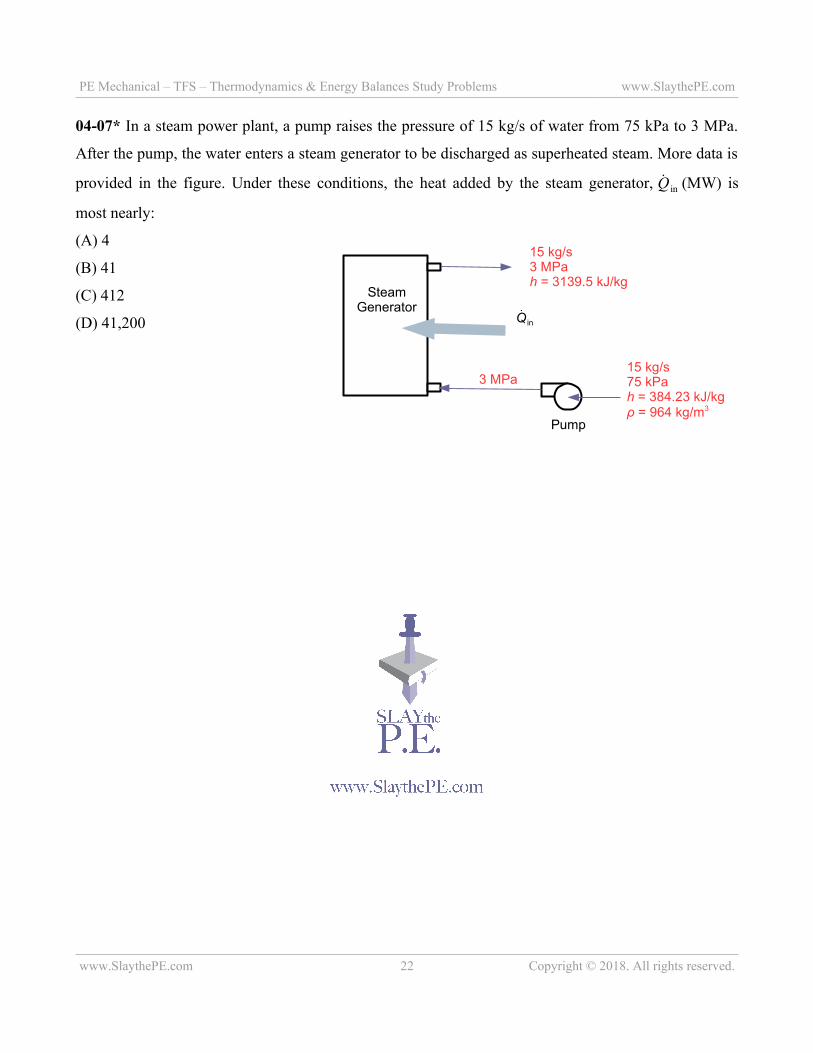
04-07* In a steam power plant, a pump raises the pressure of 15 kg/s of water from 75 kPa to 3 MPa.
After the pump, the water enters a steam generator to be discharged as superheated steam. More data is
provided in the figure. Under these conditions, the heat added by the steam generator, Q in (MW) is
most nearly:
(A) 4
(B) 41
(C) 412
(D) 41,200
www.SlaythePE.com 22 Copyright © 2018. All rights reserved.
SteamGenerator
Pump
15 kg/s75 kPah = 384.23 kJ/kgρ = 964 kg/m3
3 MPa
15 kg/s3 MPah = 3139.5 kJ/kg
Q in