Embed Size (px)
Citation preview

Journal of Physics Conference Series
OPEN ACCESS
Measurement techniques for determining the staticstiffness of foundations for machine toolsTo cite this article A Myers et al 2005 J Phys Conf Ser 13 094
View the article online for updates and enhancements
You may also likeExperimental study on vertical staticstiffnesses of polycal wire rope isolatorsPS Balaji Leblouba Moussa NomanKhandoker et al
-
Static Stiffness Optimization of RubberAbsorber Based on Taguchi MethodQuanshan Xiao Yinglong Zhao Jin Zhu etal
-
Magnetorheological elastomer withstiffness-variable characteristics based oninduced current applied to differentialmount of vehiclesUn-Chang Jeong Ji-Hyun Yoon In-HyungYang et al
-
Recent citationsCross-rail deformation modelingmeasurement and compensation for agantry slideway grinding machineconsidering thermal effectsSitong Xiang et al
-
Machine tools for large partsL Uriarte et al
-
This content was downloaded from IP address 1881491695 on 22112021 at 1107
Measurement techniques for determining the static stiffness of foundations for machine tools
A Myers1 S M Barrans and D G FordCenter for Precision Technologies University of Huddersfield UK
E-mail 1amyershudacuk
Abstract The paper presents a novel technique for accurately measuring the static stiffness of a machine tool concrete foundation using various items of metrology equipment Thefoundation was loaded in a number of different ways which simulated the erection of themachine traversing of the axes and loading of the heaviest component The results werecompared with the stiffness tolerances specified for the foundation which were deemednecessary in order that the machine alignments could be achieved This paper is a continuationof research previously published for a FEA of the foundation [1]
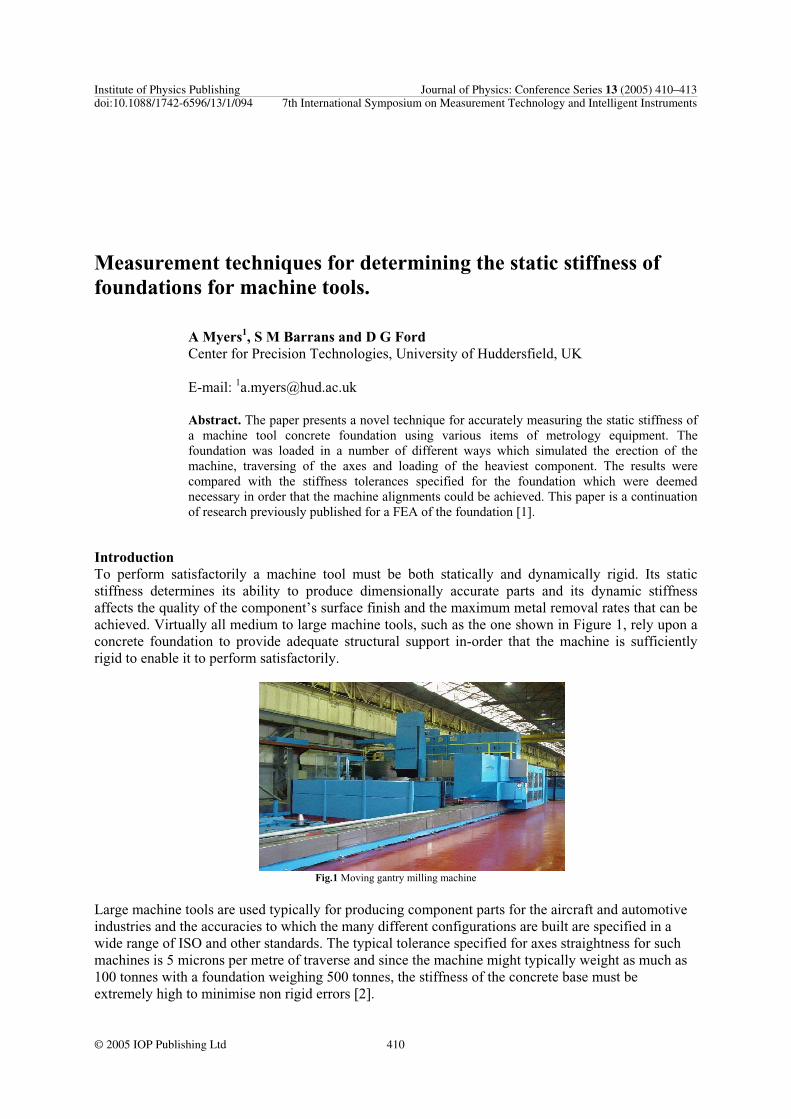
IntroductionTo perform satisfactorily a machine tool must be both statically and dynamically rigid Its staticstiffness determines its ability to produce dimensionally accurate parts and its dynamic stiffness affects the quality of the componentrsquos surface finish and the maximum metal removal rates that can be achieved Virtually all medium to large machine tools such as the one shown in Figure 1 rely upon aconcrete foundation to provide adequate structural support in-order that the machine is sufficientlyrigid to enable it to perform satisfactorily
Fig1 Moving gantry milling machine
Large machine tools are used typically for producing component parts for the aircraft and automotiveindustries and the accuracies to which the many different configurations are built are specified in a wide range of ISO and other standards The typical tolerance specified for axes straightness for such machines is 5 microns per metre of traverse and since the machine might typically weight as much as 100 tonnes with a foundation weighing 500 tonnes the stiffness of the concrete base must be extremely high to minimise non rigid errors [2]
Institute of Physics Publishing Journal of Physics Conference Series 13 (2005) 410ndash413doi1010881742-6596131094 7th International Symposium on Measurement Technology and Intelligent Instruments
410copy 2005 IOP Publishing Ltd
To illustrate how exacting the requirements are it is interesting to observe that for machines of extremely long traverse the earthrsquos curvature can be a significant proportion of the allowable tolerance A machine 40metre long might have a lsquoXrsquo axis straightness tolerance of 160 microns and the earthrsquos curvature over this distance is 32 microns
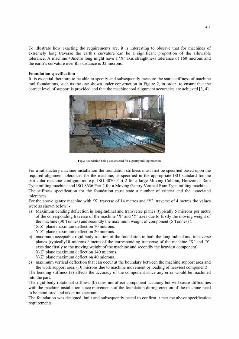
Foundation specificationIt is essential therefore to be able to specify and subsequently measure the static stiffness of machine tool foundations such as the one shown under construction in Figure 2 in order to ensure that the correct level of support is provided and that the machine tool alignment accuracies are achieved [3 4]
Fig2 Foundation being constructed for a gantry milling machine
For a satisfactory machine installation the foundation stiffness must first be specified based upon the required alignment tolerances for the machine as specified in the appropriate ISO standard for theparticular machine configuration eg ISO 3070 Part 2 for a large Moving Column Horizontal RamType milling machine and ISO 8636 Part 2 for a Moving Gantry Vertical Ram Type milling machineThe stiffness specification for the foundation must state a number of criteria and the associatedtolerancesFor the above gantry machine with lsquoXrsquo traverse of 14 metres and lsquoYrsquo traverse of 4 metres the valueswere as shown below - a) Maximum bending deflection in longitudinal and transverse planes (typically 5 microns per metre
of the corresponding traverse of the machine lsquoXrsquo and lsquoYrsquo axes due to firstly the moving weight of the machine (30 Tonnes) and secondly the maximum weight of component (5 Tonnes) )
lsquoX-Zrsquo plane maximum deflection 70 micronslsquoY-Zrsquo plane maximum deflection 20 microns
b) maximum acceptable rigid body rotation of the foundation in both the longitudinal and transverseplanes (typically10 microns metre of the corresponding tranverse of the machine lsquoXrsquo and lsquoYrsquoaxes due firstly to the moving weight of the machine and secondly the heaviest component)
lsquoX-Zrsquo plane maximum deflection 140 micronslsquoY-Zrsquo plane maximum deflection 40 microns
c) maximum vertical deflection that can occur at the boundary between the machine support area andthe work support area (10 microns due to machine movement or loading of heaviest component)
The bending stiffness (a) affects the accuracy of the component since any error would be machinedinto the partThe rigid body rotational stiffness (b) does not affect component accuracy but will cause difficultieswith the machine installation since movements of the foundation during erection of the machine needto be monitored and taken into account The foundation was designed built and subsequently tested to confirm it met the above specificationrequirements
411
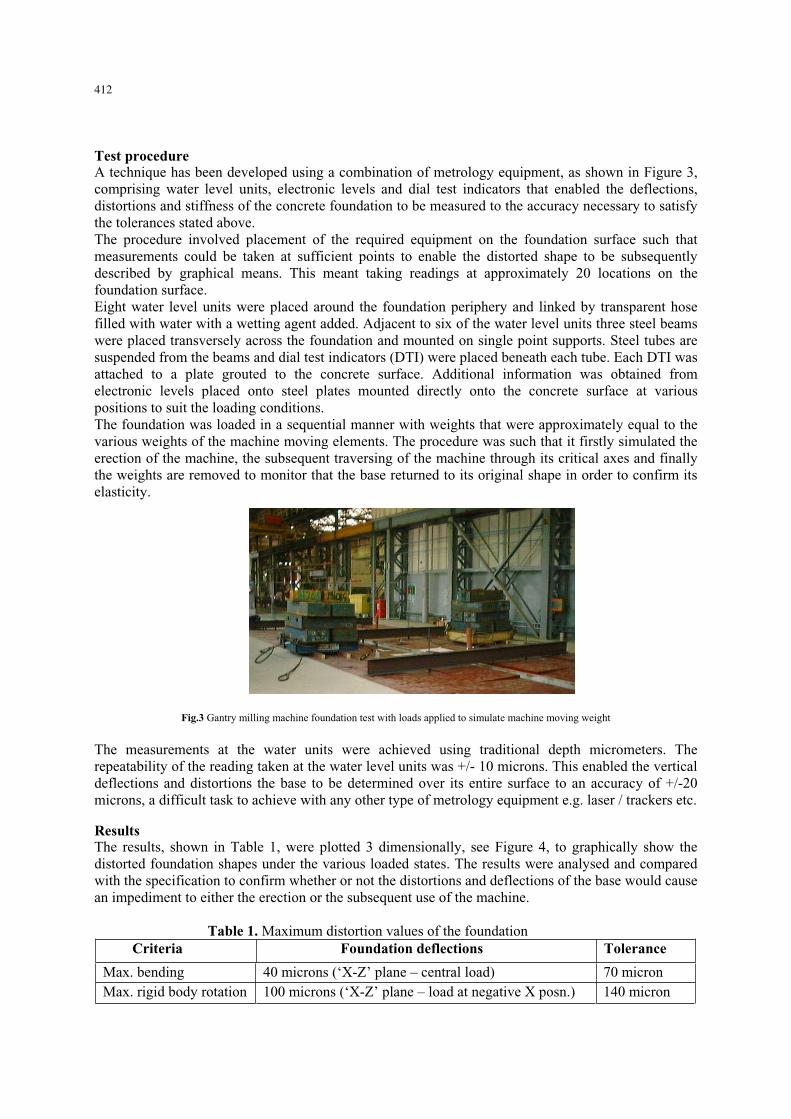
Test procedureA technique has been developed using a combination of metrology equipment as shown in Figure 3comprising water level units electronic levels and dial test indicators that enabled the deflections distortions and stiffness of the concrete foundation to be measured to the accuracy necessary to satisfythe tolerances stated above The procedure involved placement of the required equipment on the foundation surface such thatmeasurements could be taken at sufficient points to enable the distorted shape to be subsequentlydescribed by graphical means This meant taking readings at approximately 20 locations on thefoundation surface Eight water level units were placed around the foundation periphery and linked by transparent hose filled with water with a wetting agent added Adjacent to six of the water level units three steel beams were placed transversely across the foundation and mounted on single point supports Steel tubes are suspended from the beams and dial test indicators (DTI) were placed beneath each tube Each DTI wasattached to a plate grouted to the concrete surface Additional information was obtained fromelectronic levels placed onto steel plates mounted directly onto the concrete surface at various positions to suit the loading conditionsThe foundation was loaded in a sequential manner with weights that were approximately equal to thevarious weights of the machine moving elements The procedure was such that it firstly simulated the erection of the machine the subsequent traversing of the machine through its critical axes and finally the weights are removed to monitor that the base returned to its original shape in order to confirm itselasticity
Fig3 Gantry milling machine foundation test with loads applied to simulate machine moving weight
The measurements at the water units were achieved using traditional depth micrometers The repeatability of the reading taken at the water level units was +- 10 microns This enabled the verticaldeflections and distortions the base to be determined over its entire surface to an accuracy of +-20 microns a difficult task to achieve with any other type of metrology equipment eg laser trackers etc
ResultsThe results shown in Table 1 were plotted 3 dimensionally see Figure 4 to graphically show the distorted foundation shapes under the various loaded states The results were analysed and comparedwith the specification to confirm whether or not the distortions and deflections of the base would cause an impediment to either the erection or the subsequent use of the machine
Table 1 Maximum distortion values of the foundation Criteria Foundation deflections Tolerance
Max bending 40 microns (lsquoX-Zrsquo plane ndash central load) 70 micronMax rigid body rotation 100 microns (lsquoX-Zrsquo plane ndash load at negative X posn) 140 micron
412
Fig4 Results of foundation distortions due to 3 loading conditions and subsequent removal of weights
The above results were subsequently compared with a Finite Element Analysis (FEA) of the concretefoundation and which is the subject of another paper [1]
ConclusionThe test was carried out successfully and enabled the stiffness the foundation to be measured to thelevel of accuracy that was required The results showed that the foundation met the tolerances laiddown in the lsquoFoundation Specificationrsquo thus confirming that the gantry machine tool could be installed to the high level of precision specified by the alignment test sheets and that it would function correctly when in use
The test procedure took a total of three days to carry out one day to set up the equipment and two days to carry out the loading and measurements The equipment used though relatively inexpensivemet the necessary accuracy requirements
By testing a foundation in this manner before a machine is installed it is possible to determinewhether or not subsequent machining problems will occur after installation and establish where the responsibility lies
It is envisaged that by comparing the results from these and future tests on other foundations with the results obtained by FEA that the accuracy of FEA prediction will be further enhanced to give even higher levels of certainty
Acknowledgements
The support from EPSRC (EPSRC Grant GR R 35186 01 and EPSRC Grant GR R 13401 01)and industrial partners is acknowledged by the Centre for Precision TechnologiesSpecial thanks go to AsquithButler Ltd for providing measurement data
References
[1] Myers A Ford D G Barrans S M 2005 Lamdamap Conference Finite element analysis of thestatic stiffness of a foundation for a large machine tool
[2] Ford D G Postlethwaite S R Blake M D 1999 Proc Instn Mech Engrs The identification ofnon rigid error in a vertical machining centre Vol 213 Part B
[3] Brogen T H N 1970 MTIRA The stiffness of machine tool foundations Research Report No 33 [4] Brogen T H N and Stansfield F M 1970 International MTDR Conference The design of
machine tool foundations Proc 11th pp 333-353
413
Measurement techniques for determining the static stiffness of foundations for machine tools
A Myers1 S M Barrans and D G FordCenter for Precision Technologies University of Huddersfield UK
E-mail 1amyershudacuk
Abstract The paper presents a novel technique for accurately measuring the static stiffness of a machine tool concrete foundation using various items of metrology equipment Thefoundation was loaded in a number of different ways which simulated the erection of themachine traversing of the axes and loading of the heaviest component The results werecompared with the stiffness tolerances specified for the foundation which were deemednecessary in order that the machine alignments could be achieved This paper is a continuationof research previously published for a FEA of the foundation [1]
IntroductionTo perform satisfactorily a machine tool must be both statically and dynamically rigid Its staticstiffness determines its ability to produce dimensionally accurate parts and its dynamic stiffness affects the quality of the componentrsquos surface finish and the maximum metal removal rates that can be achieved Virtually all medium to large machine tools such as the one shown in Figure 1 rely upon aconcrete foundation to provide adequate structural support in-order that the machine is sufficientlyrigid to enable it to perform satisfactorily
Fig1 Moving gantry milling machine
Large machine tools are used typically for producing component parts for the aircraft and automotiveindustries and the accuracies to which the many different configurations are built are specified in a wide range of ISO and other standards The typical tolerance specified for axes straightness for such machines is 5 microns per metre of traverse and since the machine might typically weight as much as 100 tonnes with a foundation weighing 500 tonnes the stiffness of the concrete base must be extremely high to minimise non rigid errors [2]
Institute of Physics Publishing Journal of Physics Conference Series 13 (2005) 410ndash413doi1010881742-6596131094 7th International Symposium on Measurement Technology and Intelligent Instruments
410copy 2005 IOP Publishing Ltd
To illustrate how exacting the requirements are it is interesting to observe that for machines of extremely long traverse the earthrsquos curvature can be a significant proportion of the allowable tolerance A machine 40metre long might have a lsquoXrsquo axis straightness tolerance of 160 microns and the earthrsquos curvature over this distance is 32 microns
Foundation specificationIt is essential therefore to be able to specify and subsequently measure the static stiffness of machine tool foundations such as the one shown under construction in Figure 2 in order to ensure that the correct level of support is provided and that the machine tool alignment accuracies are achieved [3 4]
Fig2 Foundation being constructed for a gantry milling machine
For a satisfactory machine installation the foundation stiffness must first be specified based upon the required alignment tolerances for the machine as specified in the appropriate ISO standard for theparticular machine configuration eg ISO 3070 Part 2 for a large Moving Column Horizontal RamType milling machine and ISO 8636 Part 2 for a Moving Gantry Vertical Ram Type milling machineThe stiffness specification for the foundation must state a number of criteria and the associatedtolerancesFor the above gantry machine with lsquoXrsquo traverse of 14 metres and lsquoYrsquo traverse of 4 metres the valueswere as shown below - a) Maximum bending deflection in longitudinal and transverse planes (typically 5 microns per metre
of the corresponding traverse of the machine lsquoXrsquo and lsquoYrsquo axes due to firstly the moving weight of the machine (30 Tonnes) and secondly the maximum weight of component (5 Tonnes) )
lsquoX-Zrsquo plane maximum deflection 70 micronslsquoY-Zrsquo plane maximum deflection 20 microns
b) maximum acceptable rigid body rotation of the foundation in both the longitudinal and transverseplanes (typically10 microns metre of the corresponding tranverse of the machine lsquoXrsquo and lsquoYrsquoaxes due firstly to the moving weight of the machine and secondly the heaviest component)
lsquoX-Zrsquo plane maximum deflection 140 micronslsquoY-Zrsquo plane maximum deflection 40 microns
c) maximum vertical deflection that can occur at the boundary between the machine support area andthe work support area (10 microns due to machine movement or loading of heaviest component)
The bending stiffness (a) affects the accuracy of the component since any error would be machinedinto the partThe rigid body rotational stiffness (b) does not affect component accuracy but will cause difficultieswith the machine installation since movements of the foundation during erection of the machine needto be monitored and taken into account The foundation was designed built and subsequently tested to confirm it met the above specificationrequirements
411
Test procedureA technique has been developed using a combination of metrology equipment as shown in Figure 3comprising water level units electronic levels and dial test indicators that enabled the deflections distortions and stiffness of the concrete foundation to be measured to the accuracy necessary to satisfythe tolerances stated above The procedure involved placement of the required equipment on the foundation surface such thatmeasurements could be taken at sufficient points to enable the distorted shape to be subsequentlydescribed by graphical means This meant taking readings at approximately 20 locations on thefoundation surface Eight water level units were placed around the foundation periphery and linked by transparent hose filled with water with a wetting agent added Adjacent to six of the water level units three steel beams were placed transversely across the foundation and mounted on single point supports Steel tubes are suspended from the beams and dial test indicators (DTI) were placed beneath each tube Each DTI wasattached to a plate grouted to the concrete surface Additional information was obtained fromelectronic levels placed onto steel plates mounted directly onto the concrete surface at various positions to suit the loading conditionsThe foundation was loaded in a sequential manner with weights that were approximately equal to thevarious weights of the machine moving elements The procedure was such that it firstly simulated the erection of the machine the subsequent traversing of the machine through its critical axes and finally the weights are removed to monitor that the base returned to its original shape in order to confirm itselasticity
Fig3 Gantry milling machine foundation test with loads applied to simulate machine moving weight
The measurements at the water units were achieved using traditional depth micrometers The repeatability of the reading taken at the water level units was +- 10 microns This enabled the verticaldeflections and distortions the base to be determined over its entire surface to an accuracy of +-20 microns a difficult task to achieve with any other type of metrology equipment eg laser trackers etc
ResultsThe results shown in Table 1 were plotted 3 dimensionally see Figure 4 to graphically show the distorted foundation shapes under the various loaded states The results were analysed and comparedwith the specification to confirm whether or not the distortions and deflections of the base would cause an impediment to either the erection or the subsequent use of the machine
Table 1 Maximum distortion values of the foundation Criteria Foundation deflections Tolerance
Max bending 40 microns (lsquoX-Zrsquo plane ndash central load) 70 micronMax rigid body rotation 100 microns (lsquoX-Zrsquo plane ndash load at negative X posn) 140 micron
412
Fig4 Results of foundation distortions due to 3 loading conditions and subsequent removal of weights
The above results were subsequently compared with a Finite Element Analysis (FEA) of the concretefoundation and which is the subject of another paper [1]
ConclusionThe test was carried out successfully and enabled the stiffness the foundation to be measured to thelevel of accuracy that was required The results showed that the foundation met the tolerances laiddown in the lsquoFoundation Specificationrsquo thus confirming that the gantry machine tool could be installed to the high level of precision specified by the alignment test sheets and that it would function correctly when in use
The test procedure took a total of three days to carry out one day to set up the equipment and two days to carry out the loading and measurements The equipment used though relatively inexpensivemet the necessary accuracy requirements
By testing a foundation in this manner before a machine is installed it is possible to determinewhether or not subsequent machining problems will occur after installation and establish where the responsibility lies
It is envisaged that by comparing the results from these and future tests on other foundations with the results obtained by FEA that the accuracy of FEA prediction will be further enhanced to give even higher levels of certainty
Acknowledgements
The support from EPSRC (EPSRC Grant GR R 35186 01 and EPSRC Grant GR R 13401 01)and industrial partners is acknowledged by the Centre for Precision TechnologiesSpecial thanks go to AsquithButler Ltd for providing measurement data
References
[1] Myers A Ford D G Barrans S M 2005 Lamdamap Conference Finite element analysis of thestatic stiffness of a foundation for a large machine tool
[2] Ford D G Postlethwaite S R Blake M D 1999 Proc Instn Mech Engrs The identification ofnon rigid error in a vertical machining centre Vol 213 Part B
[3] Brogen T H N 1970 MTIRA The stiffness of machine tool foundations Research Report No 33 [4] Brogen T H N and Stansfield F M 1970 International MTDR Conference The design of
machine tool foundations Proc 11th pp 333-353
413
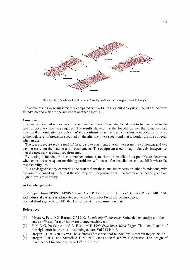