Embed Size (px)
Citation preview
American Geographical Society
Meandering Arroyos of the Dry SouthwestAuthor(s): John LeighlySource: Geographical Review, Vol. 26, No. 2 (Apr., 1936), pp. 270-282Published by: American Geographical SocietyStable URL: http://www.jstor.org/stable/209342 .
Accessed: 09/05/2014 13:27
Your use of the JSTOR archive indicates your acceptance of the Terms & Conditions of Use, available at .http://www.jstor.org/page/info/about/policies/terms.jsp
.JSTOR is a not-for-profit service that helps scholars, researchers, and students discover, use, and build upon a wide range ofcontent in a trusted digital archive. We use information technology and tools to increase productivity and facilitate new formsof scholarship. For more information about JSTOR, please contact [email protected].
.
American Geographical Society is collaborating with JSTOR to digitize, preserve and extend access toGeographical Review.
http://www.jstor.org
This content downloaded from 194.29.185.42 on Fri, 9 May 2014 13:27:45 PMAll use subject to JSTOR Terms and Conditions
MEANDERING ARROYOS OF THE DRY SOUTHWEST
John Leighly University of California, Berkeley, California
HE recently cut arroyos of the Colorado Plateau and adjacent parts of the dry Southwest owe their prominence in scientific literature largely to the enlightening account of them by Kirk
Bryan published in I925.1 The decade that has passed since the
appearance of Bryan's paper has not seen the accumulation of new data that its author hoped to evoke. During this period, however, opinion seems to have crystallized that overgrazing, rather than one of the other agents cited by Bryan, has caused excavation of the arroyos. A recent paper by Reed W. Bailey2 may perhaps be taken as register- ing both the identification of overgrazing as the agent that has released the potentially destructive powers of runoff in the Southwest and the focusing of conservationist interest on its consequences. Aside from the well founded claim that these always striking and frequently appalling evidences of misuse of land in a dry climate must have on conservationist interest, they exemplify in a considerably simplified form-as compared with the channels of permanent streams in humid climates-the action of running water in sculpturing the land surface. It is from this latter viewpoint that they are brought under scrutiny in this article.
In the summer of 1934 I was a member of a scientific party, led by Carl Sauer, that worked in the Southwest under the Soil Erosion Service of the Department of the Interior (now the Soil Conservation Service of the Department of Agriculture). From the beginning of our field work I was impressed by the sinuosity of many arroyos. As
opportunity offered I mapped representative sections of them, paying particular attention to their sinuosities, many of which can without any stretching of the term be called "meanders." At the end of the field period I was able to devote a week exclusively to the completion of the series of maps already begun. The maps, reproduced in the
accompanying figures, form the basis of the following discussion, which deals primarily with the meandering of the channels mapped.
The arroyos are cut in unconsolidated or poorly consolidated alluvial deposits and so change much more rapidly than do the chan- nels of permanent streams in humid regions, which have provided the material for previous discussions of meandering in streams. The
equilibrium between drainage and land surface in the Southwest has
1 Date of Channel Trenching (Arroyo Cutting) in the Arid Southwest; Science, Vol. 62 (N.S.), 1925, pp. 338-344.
2 Epicycles of Erosion in the Valleys of the Colorado Plateau Province, Journ. of Geol., Vol. 43, 1935, pp. 337-355.
270
This content downloaded from 194.29.185.42 on Fri, 9 May 2014 13:27:45 PMAll use subject to JSTOR Terms and Conditions
MEANDERING ARROYOS
been disturbed only recently, and a new equilibrium is not yet attained. One finds, therefore, channels in all stages of development. I have thought that observations of these rapidly changing channels might throw light on the general problem of meandering in streams, though I have not ventured in the present article to apply any of the conclu- sions arrived at to the streams of humid regions. It is possible, more- over, that the series of maps reproduced does not include all the significant modalities of sinuous arroyos in the Southwest.
All the maps were made in northwestern New Mexico, within an area extending southward from the eastern part of the Navajo Indian Reservation through the Zufii Reservation to some distance south of El Morro National Monument. The mapping was done by compass and pacing, but with care, so that as high a degree of ac- curacy may be claimed for it as for ordinary plane-table work. As reproduced, the maps are so oriented that the direction of flow of water in the channels is in all cases from right to left across the page.
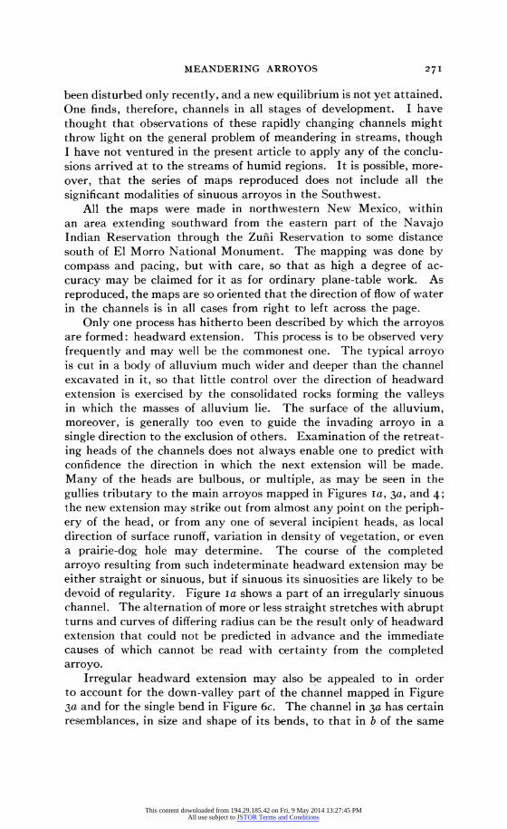
Only one process has hitherto been described by which the arroyos are formed: headward extension. This process is to be observed very frequently and may well be the commonest one. The typical arroyo is cut in a body of alluvium much wider and deeper than the channel excavated in it, so that little control over the direction of headward extension is exercised by the consolidated rocks forming the valleys in which the masses of alluvium lie. The surface of the alluvium, moreover, is generally too even to guide the invading arroyo in a single direction to the exclusion of others. Examination of the retreat- ing heads of the channels does not always enable one to predict with confidence the direction in which the next extension will be made. Many of the heads are bulbous, or multiple, as may be seen in the gullies tributary to the main arroyos mapped in Figures Ia, 3a, and 4; the new extension may strike out from almost any point on the periph- ery of the head, or from any one of several incipient heads, as local direction of surface runoff, variation in density of vegetation, or even a prairie-dog hole may determine. The course of the completed arroyo resulting from such indeterminate headward extension may be either straight or sinuous, but if sinuous its sinuosities are likely to be devoid of regularity. Figure Ia shows a part of an irregularly sinuous channel. The alternation of more or less straight stretches with abrupt turns and curves of differing radius can be the result only of headward extension that could not be predicted in advance and the immediate causes of which cannot be read with certainty from the completed arroyo.
Irregular headward extension may also be appealed to in order to account for the down-valley part of the channel mapped in Figure 3a and for the single bend in Figure 6c. The channel in 3a has certain resemblances, in size and shape of its bends, to that in b of the same
271
This content downloaded from 194.29.185.42 on Fri, 9 May 2014 13:27:45 PMAll use subject to JSTOR Terms and Conditions

THE GEOGRAPHICAL REVIEW
figure, another part of the same stream. But it can hardly be asserted that its pattern of bends is developing toward 3b. The sinuosities of the channel walls seem rather to be in process of elimination, and the arroyo seems to be developing directly toward the final form of such channels, an excavation wide and straight enough to carry flood discharges without suffering serious attack on its walls.
a 0o 5o qoo Maximum depth about 8 ft. m0ter
II W*-?;lIue
O.ms511, . UNalSTUBE D LLEvt FIlL
Symbols: O Stream bed at low water
i1i: Sand bar _4 Stranded lumps of wall material (ASire' Quiescent channel wall
.S-h) Actively retreating channel wall b - 5er 100
~~~~D me ~rs~^ melers C I 50~meirs GALLUP-17mies
Maximum depth about 8 ft. Maximum deoth about 8 ft. EOGR REViEW, APR 1936
FIG. I-Maps of sections of arroyos in northwestern New Mexico: a, near Fort Defiance road, Navajo Indian Reservation, about 3 miles west of its intersection with U. S. Highway 666; b, Mexican Springs Wash where U. S. Highway 666 crosses it; c, a tributary of Zuni Creek, Zufii Indian Reserva- tion, I mile south of Zufii Pueblo.
There is therefore little observational basis for thinking that such rhythmic meander patterns as are mapped in Figures Ib, 3b, and 4 have developed out of the irregular bends to which indeterminate headward extension gives rise. Figure Ic may also belong in this list, but it is farther along in the course of development toward the final form of arroyo than the other channels mapped, and the earlier states of its bends are correspondingly obscure. The history of change in the channels represented in Figures Ib, 3b, and 4 is fairly well recorded in the outlines of the channel walls and the shape and extent of the areas that have formerly been parts of the channel floors. These channels have had regular sinuosities from the time they were ex- cavated. The origin of regular or rhythmic sinuosities in the arroyos, which will be frankly called "meanders" in the following, is the first question to be discussed.
PRIMARY MEANDERING IN THE DRAINAGE CHANNELS
At the present time it is difficult to find alluvial valleys from which one may judge the character of the drainage lines that existed before the arroyos were cut. Of the channels mapped, those in Figures 2
272
This content downloaded from 194.29.185.42 on Fri, 9 May 2014 13:27:45 PMAll use subject to JSTOR Terms and Conditions
MEANDERING ARROYOS
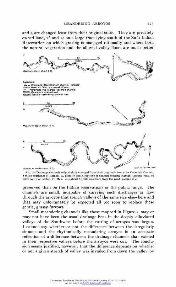
and 3 are changed least from their original state. They are privately owned land, 2b and 2C on a large tract lying south of the Zufii Indian Reservation on which grazing is managed rationally and where both the natural vegetation and the alluvial valley floors are much better
a o 50 100
Symbols: a _ Undrained depressions In channel; "tanques' t:)ui:. Bare surface; in channel, of sand -- Drainage line in grass-covered channel i-_'h.n. Quiescent channel wall
uctiSvS Actively retreating channel wall
b
Maximum depth about 5 ft.
o
Maximum denth about 5 ft. GEOG REVIEW. APR.1936
FIG. 2-Drainage channels only slightly changed from their original state: a, in Cebolleta Canyon, 5 miles southeast of Ramah, N. Mex.; b and c, sections of channel crossing Ramah-Atarque road, 92 miles south of Gallup, N. Mex. b is about 3 mile upstream from the road crossing in c.
preserved than on the Indian reservations or the public range. The channels are small, incapable of carrying such discharges as flow through the arroyos that trench valleys of the same size elsewhere and that may unfortunately be expected all too soon to replace these gentle, grassy furrows.
Small meandering channels like those mapped in Figure 2 may or may not have been the usual drainage lines in the deeply alluviated valleys of the Southwest before the cutting of arroyos was begun. I cannot say whether or not the difference between the irregularly sinuous and the rhythmically meandering arroyos is an accurate reflection of a difference between the drainage channels that existed in their respective valleys before the arroyos were cut. The conclu- sion seems justified, however, that the difference depends on whether or not a given stretch of valley was invaded from down the valley by
273
This content downloaded from 194.29.185.42 on Fri, 9 May 2014 13:27:45 PMAll use subject to JSTOR Terms and Conditions

THE GEOGRAPHICAL REVIEW
a headward-extending arroyo before the local drainage channel was deepened by the process caught in an early stage in Figure 2a. If the primary channel was in its primitive shallow state, the new channel extending up-valley might easily trench the alluvium wholly inde-
a ? 5SE'WI
Maximum depth about 30 ft.
Symbols: o Stream bed at low water stage
-.;';.. ::.. Bars, abandoned channels, terrace surfaces Jchanel1 Quiescent channel wall Schs.S) Actively retreating channel wall
Maximum depth about 7 ft. r C-EOCR PEVIE, APR 19.6
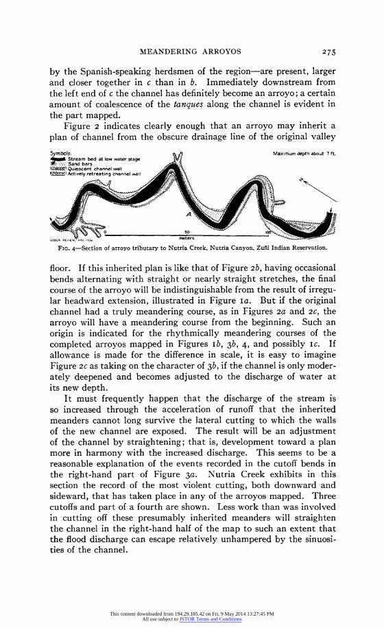
FIG. 3-Two sections of Nutria Creek, Zufli Indian Reservation: a, on Nutria Canyon road about 3/ mile east of its intersection with the Gallup-Ramah road; b, about 2 miles upstream from a.
pendently of it. The question posed could doubtless be answered, even where the arroyos have been completed, through study of the courses of the arroyos, traces of earlier channels, and cross profiles of the alluvial valley floors.
The process by which the channels of Figure 2 are being changed into steep-walled arroyos is obviously very different from the irregular headward extension that produced the channel mapped in Figure Ia. The initial breaks in the grassy bottoms of the drainage ways have the form of discrete excavations, located at the places where in the general run of meandering streams the most intense attacks on the channel are to be expected. Where the rate of cutting is slight, as in 2a, the growth of grass and sedge may be sufficient to keep the localized excavations within safe limits. But if the cutting proceeds at an accelerated rate, the grass can neither heal the surfaces exposed by excavation of the channel nor maintain a saving cover of vegetation in the stretches where the grass growing in the channel is buried under the sand washed out of the excavations. The drainage line mapped in Figures 2b and 2C is in a late stage of its existence as a shallow channel. All along its length the discrete depressions-called tanques
274
This content downloaded from 194.29.185.42 on Fri, 9 May 2014 13:27:45 PMAll use subject to JSTOR Terms and Conditions
MEANDERING ARROYOS
by the Spanish-speaking herdsmen of the region-are present, larger and closer together in c than in b. Immediately downstream from the left end of c the channel has definitely become an arroyo; a certain amount of coalescence of the tanques along the channel is evident in the part mapped.
Figure 2 indicates clearly enough that an arroyo may inherit a
plan of channel from the obscure drainage line of the original valley
Symbols: f_ Maximum depth about 7 ft. Stream bed at low water stage v
:.......:: Sand bars , .~. Q(A4P=!) Quiescent channel wall (ch2&aPnl) Actively retreating channel wall
FIG. 4-Section of arroyo tributary to Nutria Creek, Nutria Canyon, Zufii Indian Reservation.
floor. If this inherited plan is like that of Figure 2b, having occasional bends alternating with straight or nearly straight stretches, the final course of the arroyo will be indistinguishable from the result of irregu- lar headward extension, illustrated in Figure Ia. But if the original channel had a truly meandering course, as in Figures 2a and 2c, the arroyo will have a meandering course from the beginning. Such an origin is indicated for the rhythmically meandering courses of the completed arroyos mapped in Figures Ib, 3b, 4, and possibly ic. If allowance is made for the difference in scale, it is easy to imagine Figure 2c as taking on the character of 3b, if the channel is only moder- ately deepened and becomes adjusted to the discharge of water at its new depth.
It must frequently happen that the discharge of the stream is so increased through the acceleration of runoff that the inherited meanders cannot long survive the lateral cutting to which the walls of the new channel are exposed. The result will be an adjustment of the channel by straightening; that is, development toward a plan more in harmony with the increased discharge. This seems to be a reasonable explanation of the events recorded in the cutoff bends in the right-hand part of Figure 3a. Nutria Creek exhibits in this section the record of the most violent cutting, both downward and sideward, that has taken place in any of the arroyos mapped. Three cutoffs and part of a fourth are shown. Less work than was involved in cutting off these presumably inherited meanders will straighten the channel in the right-hand half of the map to such an extent that the flood discharge can escape relatively unhampered by the sinuosi- ties of the channel.
275
This content downloaded from 194.29.185.42 on Fri, 9 May 2014 13:27:45 PMAll use subject to JSTOR Terms and Conditions
THE GEOGRAPHICAL REVIEW
No comparable changes in the courses of the other meandering arroyos are to be noted. Some cutting off may eventually occur in the channel mapped in Figure 3b, but the straightening that has already been accomplished in all the channels except 3a has been done by gradual attrition of the ends of the meander lobes rather than by the violent amputation of whole meanders.
THE SHAPE OF THE MEANDERS
Earlier discussions of the shapes of meanders have been based on the examination of topographic maps and the comparison on them of stream bends differing greatly in size and orientation. Their authors seem to have supposed that the form toward which meanders tend is the arc of a circle. A better method of comparison than the simple contemplation of maps is not difficult to devise. All the quali- ties to be compared can be subjected to measurement and numerical expression, and it seems better to abstract the measurable qualities from the map than to depend on the simple judgment of the eye.
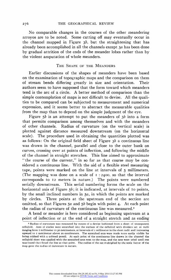
Figure 5b is an attempt to put the meanders of 3b into a form that permits comparison among themselves and with the meanders of other channels. Radius of curvature (on the vertical scale) is plotted against distance measured downstream (on the horizontal scale). The procedure used in obtaining the quantities plotted was as follows: On the original field sheet of Figure 3b a continuous line was drawn in the channel, parallel and close to the outer bank on curves, crossing over at points of inflection, and following the middle of the channel in straight stretches. This line aimed to approximate "the course of the current," in so far as that course may be con- sidered a continuous line. With the aid of a flexible steel measuring tape, points were marked on the line at intervals of 5 millimeters. (The mapping was done on a scale of I : 2400, so that the interval corresponds to I2 meters in nature.) The points were numbered serially downstream. This serial numbering forms the scale on the horizontal axis of Figure 5b; it is indicated, at intervals of 10 points, by the small inclined numbers in 5a, in which the points are marked by circles. Three points at the upstream end of the section are omitted, so that Figures 5a and 5b begin with point 4. At each point the radius of curvature of the continuous line was measured.3
A bend or meander is here considered as beginning upstream at a point of inflection or at the end of a straight stretch and as ending
3 Radius of curvature was measured by means of a device fashioned from a sheet of transparent celluloid. Arcs of circles were scratched into the surface of the celluloid with dividers set at radii ranging from i millimeter to 30 centimeters, at intervals of I millimeter in the short radii and increasing upward to i centimeter above 20 centimeters. The scratched arcs were made more easily visible by being rubbed with a colored pencil. At each point of the continuous line drawn in the channel the celluloid sheet was applied with the scratched arcs next to the map, and the arcs were tried until one was found that fitted the line at that point. The radius of the arc multiplied by the scale factor of the map gave the radius of curvature in nature.
276
This content downloaded from 194.29.185.42 on Fri, 9 May 2014 13:27:45 PMAll use subject to JSTOR Terms and Conditions

MEANDERING ARROYOS
downstream at another point of inflection or straightening. The bends of Figure 3b are numbered serially downstream in Figure 5; 5a serves to identify the bends on the map with the corresponding graphs of radius of curvature in 5b. The spaces under the graphs of
0400~
2[
o
o o6 6.6, o 6?20
0 o 5 20 30 40 50 60 0 60 90
~300 ~ ? ~
I'iAStAX SX .n200
0k g REIEW, AP 1936 01
FIG. 5-a, index diagram to points at which radius of curvature was measured on the original of
Figure 3b, and to the serial numbering of the meanders; b, graphs of radius of curvature in the meanders of the section of Nutria Creek mapped in Figure 3b.
radius of curvature in the individual bends, in 5b, are shaded sepa- rately; the blank intervals between them represent straight stretches. The blank intervals are very short at simple points of inflection and longer where the straight stretch is of measurable length. All the bends are represented in the drawing, though little significance is
to be attached to the short or poorly developed ones, numbers , 3,
.:,200
g is 19 23 2422
6, 0I, 1I, 1 24, 15, and .60 170
Several shapes of bend are recognizable, and it is difficult at first glance to say which are typical. One conclusion, however, is safe: no bend resembles the arc of a circle, which, having a constant radius
. 5-a, index diagram to points at which radius of curvature would be represented n Figure by a straight linal of Figure 3b, andallel to the horizontal numaxis of the figure. Ins, graphs of radius of curvature in the meanders
of the section of Nutria Creek -mapped in Figure 3b.
radius of curvature changes along the course of a bend, in a manner haded sepa-
rately; the blank intervals between them represent straight stretches.
e defined intervals of the position of thhort at simple point of inflectimum radius of curvatu where the straight stretch is of tmeasure lenth. Allwhich the
bends are represented in the drawing, though little significance is to be attached to the short or poorly developed ones, numbers i, 3, 6, io, Ii, 14, 15, and i8.
Several shapes of bend are recognizable, and it is difficult at first glance to say which are typical. One conclusion, however, is safe: no bend resembles the arc of a circle, which, having a constant radius of curvature, would be represented in Figure 5b by a straight line parallel to the horizontal axis of the figure. Instead, the radius of curvature changes along the course of a bend, in a manner that may be defined in terms of the position of the point of minimum radius of curvature-the vertex of the bend-and the rate at which the
277
This content downloaded from 194.29.185.42 on Fri, 9 May 2014 13:27:45 PMAll use subject to JSTOR Terms and Conditions
THE GEOGRAPHICAL REVIEW
radius of curvature changes upstream and downstream from the vertex. The bends that give character to the course of the stream in the section mapped are those numbered 2, 4, 5, 7, 8, 9, 12, 13, I6, 17, 19, 20, 21, 22, 23, 24, and 25. They may be classified as follows, on the basis of the position of the vertex:
I. Vertex upstream from the middle of the bend: 2, 7, 8, 9, 13, 17, I9, 21, 23, and 25.
2. Vertex at about the middle of the bend: 12, 20, and 22.
3. Vertex downstream from the middle of the bend: 4. 4. Two vertices, one near the upstream and one near the down-
stream end: 5, I6, and 24. If the downstream vertex were not
present, these would fall in group I. From this classification it may be concluded that the typical
bend in the channel has the shape of bends 2, 9, 17, I9, 21, and 25, in which there is a rapid decrease in radius of curvature downstream to the vertex, and downstream from the vertex either a steady in-
crease, as in 14, or, more frequently, first a slow and then a more
rapid increase, as in 9 or 17. The other types may be derived from this by a shifting of the vertex downstream or by the development, as in 5, I6, and 24, of a second vertex near the downstream termination of the bend.
Plotting radius of curvature as a function of position along the channel permits a rational discussion of the changes, if any, undergone by a bend in the process of its migration down-valley. A considerable
migration is recorded, in the form of bars and terrace surfaces, in bends 8, 9, 12, 13, I6, 19, 21, and 22. Of these bends that have
migrated farthest down-valley, only 12, I6, and 22 depart notably from the typical pattern: 12 and 22 by the location of the vertex at about the middle of the bend and I6 by the presence of a second vertex near the downstream end. I have measured radii of curvature along only one of the abandoned meander reentrants mapped in Figure 3b- the outermost one at bend 9. The plot of the radii of curvature of the edge of this reintrant is not reproduced here; the radius at the vertex is somewhat greater than in the present channel, but the form of the bend, as defined by the location of the vertex and the rate of
change in radius of curvature upstream and downstream from it, is almost identical with that of the outer bank of the present bend.
One may conclude from this examination of the bends of Figure 3b that what was above called the "typical" shape of meander is
stable, in the sense that it may migrate down-valley without essential
change. Occasionally the vertex is shifted downstream to the middle of the bend or even beyond, or a second vertex is formed near the downstream end. But these changes are not inherent in the process of down-valley migration.
One process is clearly visible that makes for the shifting down-
278
This content downloaded from 194.29.185.42 on Fri, 9 May 2014 13:27:45 PMAll use subject to JSTOR Terms and Conditions
MEANDERING ARROYOS
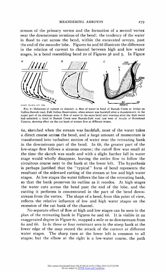
stream of the primary vertex and the formation of a second vertex near the downstream terminus of the bend: the tendency of the water in flood to cut across the bend, within the excavated arroyo, past the end of the meander lobe. Figures 6a and 6b illustrate the difference in the relation of current to channel between high and low water stages, in a bend resembling bend 20 of Figures 3b and 5. In Figure
a b C rock y///// ^y^:^^// outcrop-'
^ l ......
,,,- ,
:rock
GEOSR REVIEW , PR 193650 100
GEOGR REVIEW, APR 1936 meters
FIG. 6-Relations of current to channel: a, flow of water in bend of Ramah Creek at bridge on Gallup-Ramah road, Zufii Indian Reservation, when stream was bankfull after a thunderstorm in the upper part of its drainage area; b, flow of water in the same bend next morning after the high water had subsided; c, bend in Ramah Creek near Ramah-Zuii road just west of mouth of Horsehead Canyon, showing effect on the cut bank of stream flow at different stages.
6a, sketched when the stream was bankfull, most of the water takes a direct course across the bend, and a large amount of momentum is transformed into turbulent motion of water near the retreating bank in the downstream part of the bend. In 6b, the greater part of the low-stage flow follows a sinuous course; the cutoff flow was small at the time the sketch was made and with a slight further fall in water stage would wholly disappear, leaving the entire flow to follow the circuitous course next to the bank at the lower left. The hypothesis is perhaps justified that the "typical" form of bend represents the resultant of the sideward cutting of the stream at low and high water stages. At low stages the water follows the line of the retreating bank, so that the bank preserves its outline as it recedes. At high stages the water cuts across the bend past the end of the lobe, and the cutting it performs is concentrated in the part of the bend down- stream from the vertex. The shape of a bend, from this point of view, reflects the relative influence of low and high water stages on the recession of the cut bank of the channel.
No separate effect of flow at high and low stages can be seen in the plan of the retreating bank in Figures 6a and 6b. It is visible in an exaggerated degree in Figure 6c, mapped a mile or so downstream from 6a and 6b. In 6c three or four reentrant arcs in the steep bank at the lower edge of the map record the attack of the current at different water stages. The sharp turn at the lower left is common to all stages; but the elbow at the right is a low-water course, the path
279
This content downloaded from 194.29.185.42 on Fri, 9 May 2014 13:27:45 PMAll use subject to JSTOR Terms and Conditions
THE GEOGRAPHICAL REVIEW
followed by the current becoming straighter as the level of the water rises. At the low stage at which the bend was mapped, the stream (here the black represents an actual water surface) was dissecting the enveloping alluvium from about the lava outcrop at the elbow. At high stages the same corner is the scene of deposition rather than of erosion.
Discussion of the shapes of meanders in the foregoing has been
FA 7 i i '
15 5
0 L- I
figure-r Io - -a l be a l i 0 ay dis a o m s :\ i wt w e hw v \ z I
5\ < .:\y -s\ ' i I\
.2 .4 A .6 .8 1t0o .4 .6 ,.8 . LO1 ,2 .4 .6 .8 1.0 .2 .4 .6 .8 I FRACTION OF DISTANCE FROM UPSTREAM TO DOWNSTREAM POINT OF INFLECTION
3EOGR. RE\I1EW, APR 9365
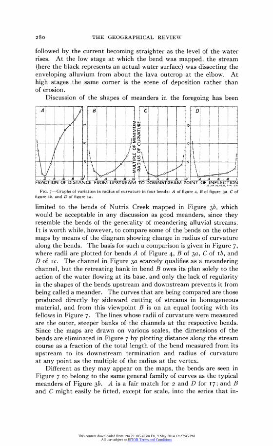
FIG. 7-Graphs of variation in radius of curvature in four bends: A of figure 4, B of figure 3a, C of figure ib, and D of figure ia.
limited to the bends of Nutria Creek mapped in Figure 3b, which would be acceptable in any discussion as good meanders, since they resemble the bends of the generality of meandering alluvial streams. It is worth while, however, to compare some of the bends on the other maps by means of the diagram showing change in radius of curvature along the bends. The basis for such a comparison is given in Figure 7, where radii are plotted for bends A of Figure 4, B of 3a, C of Ib, and D of ic. The channel in Figure 3a scarcely qualifies as a meandering channel, but the retreating bank in bend B owes its plan solely to the action of the water flowing at its base, and only the lack of regularity in the shapes of the bends upstream and downstream prevents it from being called a meander. The curves that are being compared are those produced directly by sideward cutting of streams in homogeneous material, and from this viewpoint B is on an equal footing with its fellows in Figure 7. The lines whose radii of curvature were measured are the outer, steeper banks of the channels at the respective bends. Since the maps are drawn on various scales, the dimensions of the bends are eliminated in Figure 7 by plotting distance along the stream course as a fraction of the total length of the bend measured from its upstream to its downstream termination and radius of curvature at any point as the multiple of the radius at the vertex.
Different as they may appear on the maps, the bends are seen in Figure 7 to belong to the same general family of curves as the typical meanders of Figure 3b. A is a fair match for 2 and D for 17; and B and C might easily be fitted, except for scale, into the series that in-
280
This content downloaded from 194.29.185.42 on Fri, 9 May 2014 13:27:45 PMAll use subject to JSTOR Terms and Conditions
MEANDERING ARROYOS
cludes most of the bends analyzed in Figure 5b. It would seem that we can speak of a characteristic meander form in the channels mapped, which includes the angular pendulations of Figure 4 and an actively receding section of channel wall in 3a as well as the serpentine curves of 3b and the mild reientrants of the cut banks in Ic.
Examination of Figure 7 raises the question whether the different shapes of bend there exhibited belong to one or more developmental series. If they do, then A must be at, or near, the beginning of the series, since B, C, or D may be derived from A, whereas A could be produced only from the same shape in the primary meander of the prearroyo channel or by sharply localized sideward cutting at the time the arroyo was excavated. The behavior of flood flows may account sufficiently for the downstream shift and rounding of the vertex that would change the shape of bend 2 (Figs. 3b and 5) into that of bend 8 and then of bend 13. The logical end of this course of development is the shape of bend 20 in Figures 3b and 5, in which curvature is limited to a short stretch at the vertex and the parts of the bend that displayed in earlier stages a rapid change in radius of curvature have become straight. This is definitely a low-water channel; flood flows cut across the bend without producing a notable effect on the cut bank.
In bends D and 17 the vertex seems to have remained in its normal position upstream from the middle of the bend, whereas downstream from the vertex the rate of increase in radius of curvature (measurable in Figures 5b and 7 by the slopes of the plotted lines) has decreased. This process, to judge from such bends as 4, 7, and 8 (Fig. 5b), mani- fests itself first at the vertex and produces a new phase of the bend that lengthens downstream from that point. To it may be ascribed the shape of the bends in which there is a distinct break in the graph of radius of curvature. The new phase has usurped most of the length of the bend in 17 and D, and there is no reason to believe that it may not continue its downstream extension until it includes the entire bend, except a residue that, as in the first course of development described, becomes straight. The observational data do not justify any further logical pursuit of the process, though the imagination readily invents still later phases of the same type, which would flatten the graph of radius of curvature even more and bring the bend toward the end of a second postulated course of development, toward the shape of the arc of a circle.
APPENDIX-NUMERICAL CHARACTERIZATION OF THE SHAPES OF BENDS
The plots of radii of curvature in Figures 5b and 7 frequently fall, through a certain distance along a bend, on a straight line. Considering the inaccuracies of mapping and measurement, the graphs representing increase in radius of curvature downstream from the vertex in A, Figure 7, or from the first vertex of I6, Figure 5b, may reasonably be considered approximations to straight lines, to say nothing of the graphs of 17 in Figure 5b and D in Figure 7. The graph is most frequently
28I
This content downloaded from 194.29.185.42 on Fri, 9 May 2014 13:27:45 PMAll use subject to JSTOR Terms and Conditions
THE GEOGRAPHICAL REVIEW
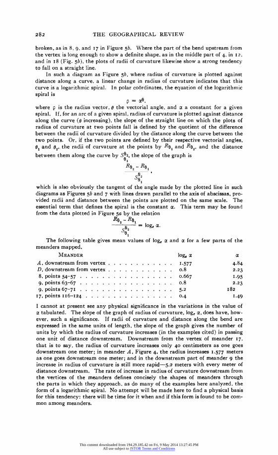
broken, as in 8, 9, and 17 in Figure 5b. Where the part of the bend upstream from the vertex is long enough to show a definite shape, as in the middle part of 4, in I2, and in I8 (Fig. 5b), the plots of radii of curvature likewise show a strong tendency to fall on a straight line.
In such a diagram as Figure 5b, where radius of curvature is plotted against distance along a curve, a linear change in radius of curvature indicates that this curve is a logarithmic spiral. In polar cobrdinates, the equation of the logarithmic spiral is
p = a0, where p is the radius vector, 0 the vectorial angle, and c a constant for a given spiral. If, for an arc of a given spiral, radius of curvature is plotted against distance along the curve (o increasing), the slope of the straight line on which the plots of radius of curvature at two points fall is defined by the quotient of the difference between the radii of curvature divided by the distance along the curve between the two points. Or, if the two points are defined by their respective vectorial angles, 01 and 02, the radii of curvature at the points by R0, and R02, and the distance
between them along the curve by S02, the slope of the graph is 01 Ro
2 R0
So2 01
which is also obviously the tangent of the angle made by the plotted line in such diagrams as Figures 5b and 7 with lines drawn parallel to the axis of abscissas, pro- vided radii and distance between the points are plotted on the same scale. The essential term that defines the spiral is the constant ac. This term may be found from the data plotted in Figure 5a by the relation
Re - Re1 0 - log, ac.
S02
The following table gives mean values of loge a and a for a few parts of the meanders mapped.
MEANDER log, a Z
A, downstream from vertex . . . . . . . . . 1.577 4.84 D, downstream from vertex . . . . . . . . .... o.8 2.23 8, points 54-57 ................. 0.667 I.95 9, points 63-67 . . . . . . . . . . . ...... o.8 2.23 9, points 67-71 . . . . . . . . . . . . ..... 5.2 I82
17, points II6-124 ................ 0.4 I.49
I cannot at present see any physical significance in the variations in the value of a tabulated. The slope of the graph of radius of curvature, log, a, does have, how- ever, such a significance. If radii of curvature and distance along the bend are expressed in the same units of length, the slope of the graph gives the number of units by which the radius of curvature increases (in the examples cited) in passing one unit of distance downstream. Downstream from the vertex of meander 17, that is to say, the radius of curvature increases only 40 centimeters as one goes downstream one meter; in meander A, Figure 4, the radius increases 1.577 meters as one goes downstream one meter; and in the downstream part of meander 9 the increase in radius of curvature is still more rapid-5.2 meters with every meter of distance downstream. The rate of increase in radius of curvature downstream from the vertices of the meanders defines concisely the shapes of meanders through the parts in which they approach, as do many of the examples here analyzed, the form of a logarithmic spiral. No attempt will be made here to find a physical basis for this tendency: there will be time for it when and if this form is found to be com- mon among meanders.
282
This content downloaded from 194.29.185.42 on Fri, 9 May 2014 13:27:45 PMAll use subject to JSTOR Terms and Conditions