Embed Size (px)
Citation preview

TESA-hite Magna 400 / 700
Instruction Instruction Instruction Instruction manualmanualmanualmanual
TESA-hite Magna 400 / 700

TESA-hite Magna 400 / 700
2

TESA-hite Magna 400 / 700
3
LIST OF CONTENTS PAGE
1 1 1 1 Main featuresMain featuresMain featuresMain features 4444
2 2 2 2 InstallationInstallationInstallationInstallation 5555 2.1 Unpacking and setting up 5 2.2 Starting the instrument 6 2.3 Short instructions for use 7
3 3 3 3 Description Description Description Description of the of the of the of the componentscomponentscomponentscomponents 9999 3.1 Instrument base 9 3.2 Vertical column, measuring head and movement of the head 9 3.3 Power supply 10 3.4 Measuring system 10 3.5 Automatic measuring value correction 10
4 4 4 4 MeasuringMeasuringMeasuringMeasuring 11111111 4.1 Basic principles 11 4.2 Display and function keys 11 4.2.1 Definition of display symbols 12 4.3 Program functions 13 4.4 Probing procedure at the contact point 15 4.5 Establishing the probe constant for length measurements
with inversion of the probing direction 16 4.6 Measuring features with flat surfaces 17 4.7 Measuring features with cylindrical surfaces 17 4.8 MODE 1, Measuring lengths in one direction, without probe constant 18 4.9 MODE 2, Measuring lengths in two directions, with probe constant 19 4.10 Procedure for detecting the culmination point 20 4.11 MODE 3, continuous display 26 4.12 PRESET function 28 4.13 Measuring parallelism deviations 32 4.14 Use of the fine adjustment 35 5 5 5 5 Instrument configurationInstrument configurationInstrument configurationInstrument configuration 35353535
6 6 6 6 Error messagesError messagesError messagesError messages 40404040
7 7 7 7 MaintenanceMaintenanceMaintenanceMaintenance 40404040 7.1 Cleaning 40 7.2 Charging the battery 41
8 8 8 8 Delivery programmeDelivery programmeDelivery programmeDelivery programme 41414141 8.1 Optional accessories 42
9 9 9 9 Technical dataTechnical dataTechnical dataTechnical data 45454545 9.1 Description of the RS 232 interface 46 9.1.1 Monodirectional data transmission 46 9.1.2 Bidirectional data transmission 46
10 10 10 10 WarrantyWarrantyWarrantyWarranty 46464646
11 11 11 11 DDDDeclaration of conformityeclaration of conformityeclaration of conformityeclaration of conformity 47474747

TESA-hite Magna 400 / 700
4
1 MAIN FEATURES
Fig. 1
Cap cover 1
Housing 2
Mounting pin 3
Probe fixing arm 4
Probe 5
Guiding and support faces 6
Cast-iron base 7
Knurled screw for locking the measuring-head drive 10
Handwheel for displacement 8
Knurled screw for the fine adjustment 9
Control panel 11

TESA-hite Magna 400 / 700
5
1 MAIN FEATURES
The TESA-Hite Magna 400 / 700 is a mains-independent height gauge, which is suitable for measuring lengths in the form of external, internal, step, height, depth and distance dimensions. A cast-iron base with finish-ground supporting face ensures the stability of the TESA-Hite Magna 400 / 700. A rigid column is located under the protective cover, equipped with a guide system that is straight. On this slides the measuring head and the movement of the head is measured by the magnetic measuring system magnaµsystem (TESA patent). The measured readings are obtained in a very simple and reliable manner. Firstly the probe is brought into contact with the point to be measured then immobilised to permit it to stabilise; then, by performing a further slight rotation of the drive system, the measured reading is automatically recorded by a dynamic process, with the measuring force at all times remaining constant. An acoustic signal confirms that the reading has been recorded and it is immediately displayed and, if required, transmitted via the RS 232 output. Cylindrical surfaces (bores and shafts) can also be measured simply and reliably by automatically probing to find the culminating point. The automatic microprocessor assisted correction makes the TESA-Hite Magna 400 / 700 even more accurate: Correction values memorised in the instrument compensate for systematic errors when measuring lengths.
2 INSTALLATION
2.1 2.1 2.1 2.1 UnpackingUnpackingUnpackingUnpacking and setting up and setting up and setting up and setting up
The TESA-Hite Magna 400/700 is delivered ex factory, packed to protect it from impact and corrosion. Please use the original packing materials for any subsequent transport. IMPORTANT: Your instrument is supplied with a 6V rechargeable battery already inserted. For recharging the battery, see section 7.2. Before fitting the standard accessories, release the measuring carriage by unscrewing the light grey knurled screw (10) Fig. 1 on the hand wheel. Securely fit the probe 5 to the probe-fixing arm 4 itself fitted to the mounting pin 3. Ensure that the two knurled screws on the probe-fixing arm are well tightened. After, unlock the measuring head by moving the slide downward until the insert touch the granite plate; exert a force on the handwheel, like if you would do a probing down; this will unlock the transport carriage from the measuring carriage. However, we recommend you firstly read this instruction manual.

TESA-hite Magna 400 / 700
6
2.2 2.2 2.2 2.2 Starting the instrumentStarting the instrumentStarting the instrumentStarting the instrument
After the instrument is turned on (ON/OFF), a double bar appears on the screen (Fig. 2)
Fig. 2
To enter in the measuring mode, move the measuring head until the reference mark has been crossed. After having crossed the reference, the TESA-Hite Magna 400 / 700 is in the measuring mode and the following display appears: Switch-on auto Print mode Establish the probe constant Enter in ZZ mode Introduction of a PRESET For more detailed information on the probing procedure for taking readings, please consult the chapter 4. Remark:Remark:Remark:Remark: By turned on, if first the F1, then the F1 and ON/OFF keys are simultaneously activated; after deactivate the ON/OFF and then the F1 keys; the instrument will go in the configurations menu. For further information about it, please consult the chapter 5.
mm
mm

TESA-hite Magna 400 / 700
7
b
h1
h2a
2.3 2.3 2.3 2.3 Short instructions for useShort instructions for useShort instructions for useShort instructions for use
Display and keys
Active functions Main display Functions available through keys F1 to F4 Function keys F1 to F4 Switching ON / OFF Cancel last function or last probing Change unit Transmit a reading to a peripheral
MODE 1 Measuring length in one direction, without calibration
mm

TESA-hite Magna 400 / 700
8
h2
2 x
b
a
h1
d
cb
h1
h2a
MODE 2 Measuring length in two directions, with calibration
With single probing With double probing With reading Display Scatter resolution 5 ÷ 10 µm 0.01 mm .0002 ÷ .0004 in .0005 in 10 ÷ 50 µm 0.1 mm .0004 ÷ .002 in .005 in 50µm 1 mm .002 in .05 in
Procedure for detecting the culmination point
Probe normally without releasing the probe; wait about 1 second in the probing zone. The system will automatically switch to culmination-point detection mode. Move either the part or the TESA-Hite Magna 400/ 700 so that measuring probe passes through the culmination point. The TESA-Hite Magna 400 / 700 has a system for automatically detecting the shape of the surface being probed (concave or convex). Hence it is not necessary to indicate to the TESA-Hite Magna 400 / 700 whether it is probing a bore or a shaft as this will be detected automatically according to the upward or downward probing of the maximum or minimum culmination point. Once the symbol ▲ or ▼ appears on the display, the system will have automatically detected the maximum or minimum point of the bore or shaft to be measured. The measuring head can now be withdrawn.
MODE 3 Continuous display

TESA-hite Magna 400 / 700
9
mm
Mode 1: 1xMode 2: 2x
+
—
« PRESET » function (mode 1, 2 and 3)
Choice:
Choice:
Shift one position to the left Confirm preselected reading Cancel preselected reading Indirect reference point
3 DESCRIPTION OF THE COMPONENTS
3.1 3.1 3.1 3.1 IIIInstrument basenstrument basenstrument basenstrument base
The base is chemically nickel-plated in order to make it very resistant to corrosion. Its lower face, which has been machined to ensure that it is rigorously flat, guarantee the stability of the TESA-Hite Magna 400 700. The lugs 6 (Fig. 1) are designed especially for supporting the TESA-Hite Magna 400 / 700 against a parallel rule or for guiding it along such a rule, for example.
3.3.3.3.2222 Vertical column, measuring head and movement of the headVertical column, measuring head and movement of the headVertical column, measuring head and movement of the headVertical column, measuring head and movement of the head
The rigid vertical column is perpendicular to the base, to which it is permanently fixed. A measuring head slides on the guide and the movement of the head is recorded by the magnetic measuring system magnaµsystem (TESA patent). The measuring head can be moved in infinitesimal increments by the fine-adjustment system, for example when using fine probes or measuring small bores. The knurled screw 9 (Fig. 1) is used to lock the measuring-head movement that is thus left free for scanning. However, if necessary, the head itself can also be locked by using the built-in system.

TESA-hite Magna 400 / 700
10
<6 N
<6 N
~ 7 mm
1.5 N
C ~ 2 mm
C ~ 2 mm~ 3 mm
0
~ 3 mm
~ 7 mm
A
1.5 N
D
D
B
B
Clamping ofClamping ofClamping ofClamping of the measuring head: the measuring head: the measuring head: the measuring head: Move the measuring slide upward until the stop; exert a force on the handwheel, like if you would do a probing up; this will lock the transport carriage on the measuring carriage. To unlock the carriage do the same, but in the opposite direction.
3.3.3.3.3333 Power Power Power Power supplysupplysupplysupply
The TESA-Hite 400 / 700 is powered by a 6V rechargeable battery (N° 00760157). This is recharged using the mains adapter N° 04761054 and the cable EU N° 04761055 or US N° 04761056 (see chapter 7.2 – Charging the battery).
3.3.3.3.4444 Measuring systemMeasuring systemMeasuring systemMeasuring system
The TESA-Hite Magna 400 / 700 incorporates the magnetic measuring system magnaµsystem which digitally records the measured dimension, called the mesurande (TESA patent). From point A, the reading system can be moved downwards to the respective trigger points. Once one of these points has been reached, the reading of the value is triggered, that is to say that the position of the measuring head in relation to the magnetic scale is read off by the sensor. The distance C, symmetrical in relation to the position of each trigger point in the travel of the measuring system is kept for seeking the culminating point when probing cylindrical surfaces. (Read section 4.7 also). A Starting position B Travel to upper or lower trigger point for taking reading C Partial measuring span for finding the culmination point D Travel in one direction from the neutral position to the spring-loaded end stop
3.3.3.3.5555 AutomaticAutomaticAutomaticAutomatic measuringmeasuringmeasuringmeasuring value correction value correction value correction value correction
It is agreed that a perfectly accurate measuring instrument is impossible to produce. Therefore, the value indicated by any instrument comprises a deviation from the true value; this deviation is composed of the bias errors and the random errors. Random errors cannot be predicted since they are the result of influences that cannot be controlled, e.g. the value dispersion. Bias errors, on the other hand, as for example the deviations of the scale divisions on the material measure or the form and positional errors of the measuring head guides can be corrected once they have been measured. To correct length measurements, after the TESA-Hite Magna 400 / 700 has been completely assembled; the actual errors are determined step-by-step by means of a system of stepped gauge

TESA-hite Magna 400 / 700
11
mmin
blocks. The correction values thus calculated will subsequently be memorised in the electronic module of the instrument. Thus, every measurement read off by the TESA-Hite Magna 400 / 700 will be automatically corrected before being displayed.
4 MEASURING
4444.1 .1 .1 .1 Basic principlesBasic principlesBasic principlesBasic principles
To measure with the TESA-Hite Magna 400 / 700 necessarily means that the way the measured values are determined depends to a large extent on the kind of measurement tasks the user has to carry out. Special attention should be paid to the main following points: • Determining the reading by one or two probe contacts • Measuring with or without change of probe direction • Measuring with or without seeking the culmination point.
4444....2222 Display and function keysDisplay and function keysDisplay and function keysDisplay and function keys
Active functions Main display Functions available through keys F1 to F4 Function keys F1 to F4 Transfer a reading to Cancel last function a peripheral or probing Change unit Switching ON / OFF

TESA-hite Magna 400 / 700
12
4444....2.12.12.12.1 Definition of display symbolsDefinition of display symbolsDefinition of display symbolsDefinition of display symbols
1 Length measurements in one direction, without probe constant (Measuring mode 1) 2 Length measurements in two directions, with probe constant (Measuring mode 2) 3 Continuous display (Measuring mode 3) 4 Display of the difference between the last two probe contacts (Measuring mode 2) 5 Display of the difference between the last two displayed readings (Measuring modes 1 and 2) 6 Measurements with 2 probe contacts per length measurement (Measuring mode 2) 7 Measurements with 1 probe contact per length measurement (Measuring mode 2) 8 Establishing a new reference (Measuring modes 1, 2 and 3) 9 «PRESET» function (presetting of numerical values) (Measuring modes 1, 2 and 3) 10 Automatic data transfer to a peripheral 11 Confirmation and further registering of data in the instrument memory 12 Increment digit, in measuring mode this indicates the detection of the maximum culmination point 13 Increment digit, in measuring mode this indicates the detection of the minimum culmination point 14 Shifting a digit to the left 15 Start the measurement of the parallelism deviation

TESA-hite Magna 400 / 700
13
4444....3333 Program Program Program Program functionsfunctionsfunctionsfunctions
MEASUREMENT TASKS
Length dimensions
Form dimensions
Step dimensions Height dimensions Depth dimensions
External dimensions: - Rib width - Shaft diameter (culmination) Internal dimensions: - Groove width - Bore diameter (culmination) Centre distances: - Ribs, shafts, grooves, bores
Determining distances during a continuous measurement process
Parallelism deviations
Measurements without change of probe direction
Measurements with change of probe direction
Without taking the probe constant
With taking the probe constant
« Continuous » display with the program functions excluded
Measuring the MAX – MIN deviation
Measuring mode 1 Measuring mode 2 Measuring mode 3

TESA-hite Magna 400 / 700
14
Measuring mode 1 Measuring mode 2 Measuring mode 3
Length measurements in one direction without probe
constant
Length measurements in two directions with probe
constant
Continuous display
TurnTurnTurnTurn instrument On instrument On instrument On instrument On
Set display to zero or
« PRESET » Mode 3
St2St2St2St2 Take the
reference point
Determine the probe constant
Measure
St1St1St1St1 Take the
reference point
Measure Measure

TESA-hite Magna 400 / 700
15
4444....4444 ProProProProbing procedure at the contact pointbing procedure at the contact pointbing procedure at the contact pointbing procedure at the contact point
In order to ensure the reliability of the measured values, the following condition must be fulfilled: the probe 5 should be firmly attached to the probe fixing arm 4 which in turn is fixed to the mounting pin 3. Make sure that both knurled screws on the fixing arm are tightened. 3 4 5 Probe contact procedure for the reading the measured values • Use the handwheel 8 (Fig. 1) to rapidly move the measuring head. • Use the knurled ring to bring the probe into contact with the measuring point on the work piece, but not right up to the switch point. • Pause for a second or so. • Approach the measuring head by continuing to turn the knurled ring slowly until an acoustic signal confirms the taking of the reading. • Withdraw the probe from the surface of the work piece. For optimum results when taking the readings, the measuring point should always be probed with the same careful regular movement. When the speed with which the measuring head approaches the work piece is reduced to an absolute minimum at the end of its travel, the probe will make precise and bounce-free contact. The readings thus obtained will be reliable and highly repeatable.

TESA-hite Magna 400 / 700
16
4444....5555 Establishing the probe coEstablishing the probe coEstablishing the probe coEstablishing the probe constanstanstanstant for length measurements nt for length measurements nt for length measurements nt for length measurements wwwwith inversion of the ith inversion of the ith inversion of the ith inversion of the probing directionprobing directionprobing directionprobing direction
When bores, shafts, grooves, etc. are measured with a change of probe direction, a gauge-head constant must be taken into account. In order that the user may effect all these measurements without having to resort to tire some calculations, the gauge-head constant is determined on a suitable master gauge whose actual dimension is known. Setting piece No. 00760231 is provided with the instrument. By combining the three gauge blocks of which it consists, it has a total internal or external dimension of 6.350 mm / .250 in.
RemarkRemarkRemarkRemark • Use only the setting piece supplied with the
TESA-Hite Magna 400 / 700 bearing with the N° 00760231 and the same production number as the instrument.
• The final TESA-Hite Magna 400 / 700 verification and the certificate supplied both refer to this reference gauge.
The gauge-head constant, which is a permanent correction factor, is calculated by the built-in program once the measurements on the master-gauge have been completed; it is then recorded and automatically taken into account for all subsequent measurements. By applying a gauge-head constant, the following features – which can affect the measurements – will be considered or compensated: • Diameter of the probe ball or disc used. • Elastic distortion of the probe and its support under the action of the measuring force. • Hysteresis errors of the measuring system. The gauge-head constant must be redetermined after any change in the measuring conditions. Main causes of change: • Turning the instrument off. • Changing the probe. • Changing the probe position. The «Determination a gauge-head constant» function requires at least two probe contacts at each measuring point. The difference between the two readings at each measuring point should not exceed 1 µm. Should the instrument indicate a greater difference, it will be displayed and the operator must either accept that difference or repeat the gauge-head constant determination operation.

TESA-hite Magna 400 / 700
17
4444....6666 MeMeMeMeasuring asuring asuring asuring featuresfeaturesfeaturesfeatures with flat surfaceswith flat surfaceswith flat surfaceswith flat surfaces
The probes used for contacting flat surfaces are those producing point contact. Such probes are either ball, barrel or disk shaped (see standard and optional accessories). In measuring mode 1, the measurements are taken exclusively by probing. All measurements must be taken in the same direction. In measuring mode 2, the measurements can involve one or two contacts and can be recorded with or without inverting the probe direction.
4444....7777 MeMeMeMeasuring features with cylindrical surfacesasuring features with cylindrical surfacesasuring features with cylindrical surfacesasuring features with cylindrical surfaces
Probes appropriate for contacting cylindrical surfaces are identical to those used for flat surfaces. If the diameter of bores or shafts has to be determine in addition to their height, the two contacts have to be made at the diametrically opposed culmination points. To determine the culminating point, proceed as follows: • Use the handwheel 8 to rapidly move the measuring head and the probe • Use the knurled ring to bring the probe into contact – slightly off centre – with the bore or shaft to be measured, but not right up to the switch point. • Pause for a second or so. • Move the measuring head forward by continuing to turn the knurled ring slowly until an acoustic signal confirms the taking of the reading. • After about 1 second, the probing force will be displayed graphically on the control-panel display. • Keep the probing force within the limits and manually move the part or the TESA-Hite Magna 400 / 700 so that the probe passes through the culmination point. Once the symbol or appears on the display, the system will have automatically detected the maximum or minimum point of the bore or shaft to be measured. • The measuring head can now be withdrawn. • Repeat the operation in the other direction to determine the diameter.

TESA-hite Magna 400 / 700
18
h2
h3
h1
b
h1
h2a
4444....8888 MODE 1 MeMODE 1 MeMODE 1 MeMODE 1 Measuring lengths in one directionasuring lengths in one directionasuring lengths in one directionasuring lengths in one direction, , , , wwwwithoutithoutithoutithout probe constantprobe constantprobe constantprobe constant
Measuring without inversion of gauge-head direction (Mode St 1) Measuring points
Automatic PrintPrintPrintPrint Available after switch-on Two possibilities for cancelling the automatic point: A)A)A)A) B)B)B)B) au
ImportantImportantImportantImportant To ensure optimum instrument measuring accuracy, the standard probe-fixing arm (N° 00760143) must be aligned on the working surface. The accessory N° 00760225 can be used to do this alignment.

TESA-hite Magna 400 / 700
19
h1
b1
h3
h2
b2
Ø 2
Ø 1
h3
h2
h1
0.000 mm.0000 in
1 4
2 3
4444....9999 MODE 2 MODE 2 MODE 2 MODE 2 MeasuringMeasuringMeasuringMeasuring lengths in two lengths in two lengths in two lengths in two direction direction direction directionssss, w, w, w, withithithith probe constantprobe constantprobe constantprobe constant
Measuring with inversion of gauge-head direction (Mode St 2) FLAT FLAT FLAT FLAT SURFACESSURFACESSURFACESSURFACES CYLINDRICAL SURFACESCYLINDRICAL SURFACESCYLINDRICAL SURFACESCYLINDRICAL SURFACES External dimensions Internal dimensions
AutomaticAutomaticAutomaticAutomatic PrPrPrPrintintintint Available after switch-on Changing the Dimension of the setting piece If the reading dispersion is too great, the display indicates: Deviation not accepted, Accept with resolution adapted recalibrate as follows: 5 ÷ 10µm 0.01 mm .0002 ÷ .0005 in .0005 in
10 ÷ 50µm 0.1 mm .0005 ÷ .002 in .005 in
> 50µm 1 mm > .002 in .05 in
ImportantImportantImportantImportant To ensure optimum instrument measuring accuracy, the standard probe-fixing arm (N° 00760143) must be aligned on the working surface with the air cushion deactivated. The accessory N° 00760225 can be used to do this alignment.

TESA-hite Magna 400 / 700
20
2 x
b
h1
h2a
h2
b
a
h1
d
c
With single probing With single probing With single probing With single probing With double probingWith double probingWith double probingWith double probing New reference New reference point point
4444....10101010 Procedure for detecting the culmination pointProcedure for detecting the culmination pointProcedure for detecting the culmination pointProcedure for detecting the culmination point
The TESA-Hite Magna 400 / 700 has an automatic system for determining the shape of the surface being probed (concave or convex). Hence, it is not necessary to indicate to the TESA-Hite Magna 400 / 700, whether the surface being probed is flat, a bore or a shaft, as it can independently detect whether there is a culminating point and, according to whether it is an upward or a downward probe, whether it is a maximum or a minimum. In short, just probe normally and release the key if the surface is flat or wait about 1 second in the probing zone to see whether the probe is in contact with a bore or a shaft and whether the diameter is to be measured. The system automatically switches to culminating-point detection mode. Then just move the part or the TESA-Hite Magna 400 / 700 so that the probe passes through the culmination point. Once the symbol or appears on the display, the system will have automatically detected the maximum or minimum point of the bore or shaft to be measured. At this point, the measuring key can be released.

TESA-hite Magna 400 / 700
21
h1
b1
h3
h2
b2
h3
h2
h1
Ø 2
Ø 1
h3
h2
h1
Plane parallel surfaces Cylindrical surfaces
REMARK:REMARK:REMARK:REMARK: Not convenient for external dimensions
Without searching for the culmination pointWithout searching for the culmination pointWithout searching for the culmination pointWithout searching for the culmination point
MEASURING
WiWiWiWith searching for the culmination pointth searching for the culmination pointth searching for the culmination pointth searching for the culmination point
WithoutWithoutWithoutWithout determiningdeterminingdeterminingdetermining Ø WithWithWithWith determiningdeterminingdeterminingdetermining Ø
With manual probing movements to find culmination points
Automatic triggering of memorising
Search for culmination point
unnecessary

TESA-hite Magna 400 / 700
22
mm
mm
mm
mm
Detailed procedure Detailed procedure Detailed procedure Detailed procedure for detecting the culmination pointfor detecting the culmination pointfor detecting the culmination pointfor detecting the culmination point
Probe/Contact Display Active keys Comments
mm /in Recording constantRecording constantRecording constantRecording constant OK. OK. OK. OK. PPPProbe referencerobe referencerobe referencerobe reference ReferenceReferenceReferenceReference OK. OK. OK. OK. PPPProbe diameterrobe diameterrobe diameterrobe diameter InternalInternalInternalInternal,,,, downward downward downward downward.... Normal probing Beep • Place the gauge head slightly off- centre with respect to the bore axis. Wait 1 second • After waiting about 1 second in the In probing zone probing zone. • Culmination proposal: if passing through the neutral point without culmination=normal probing. • Adjust the force in upper zone Move the part or the TESA-Hite Magna so that the gauge head passes through the maximum or the minimum point. Culmination point Culmination point Culmination point Culmination point detecteddetecteddetecteddetected. Beep The bar graph indicates the current measuring force.
mm

TESA-hite Magna 400 / 700
23
mm
mm
mm
mm
mm
Detailed procedure for detecting the culmination poDetailed procedure for detecting the culmination poDetailed procedure for detecting the culmination poDetailed procedure for detecting the culmination pointintintint
Probe/Contact Display Active keys Comments
Culmination pointCulmination pointCulmination pointCulmination point overshotovershotovershotovershot.... To improve accuracy, it is possible to make several passes through Beep the culmination point. Only the highest or Lowest point will be memorised. Gauge head releasedGauge head releasedGauge head releasedGauge head released.... First point memorised. Await next action. Aborts culmination. Return to last measurement displayed. • Place the gauge head slightly off- Centre with respect to the bore axis. Beep • Wait about 1 second. • Move the part or the TESA-Hite Magna Second contactSecond contactSecond contactSecond contact.... Culmination point Culmination point Culmination point Culmination point detecteddetecteddetecteddetected.... The bar graph indicates the current measuring force. End of bore measurementEnd of bore measurementEnd of bore measurementEnd of bore measurement.... Display centre of diameter

TESA-hite Magna 400 / 700
24
mm
mm
Detailed procedure for detecting the culmination pointDetailed procedure for detecting the culmination pointDetailed procedure for detecting the culmination pointDetailed procedure for detecting the culmination point
Probe/Contact Display Active keys Comments
Call up Call up Call up Call up diameterdiameterdiameterdiameter display. display. display. display. Beep Force diameter mode Cancel diameter mode ExterExterExterExternal diameternal diameternal diameternal diameter Probe, downwardProbe, downwardProbe, downwardProbe, downward.... Normal probing Beep • Place the gauge head slightly off- Centre with respect to the shaft axis. Wait 1 second • Wait 1 second in probing zone. probing zone • Adjust the force in the lower zone. Culmination Culmination Culmination Culmination proposalproposalproposalproposal.... Move the part or the TESA-Hite Magna so that the gauge head passes through the maximum or Beep Beep the minimum point. Point de rebroussement Point de rebroussement Point de rebroussement Point de rebroussement détecté. détecté. détecté. détecté. The bar graph indicates the current measuring force. Gauge head releasedGauge head releasedGauge head releasedGauge head released.... First point memorised. Await next action. Aborts culmination. Return to last measurement displayed.
mm
mm
mm

TESA-hite Magna 400 / 700
25
Detailed procedure for detecting the culmination pointDetailed procedure for detecting the culmination pointDetailed procedure for detecting the culmination pointDetailed procedure for detecting the culmination point
Probe/Contact Display Active keys Comments
• Place the gauge head slightly off- Centre with respect to the shaft axis. • Wait about 1 second. Beep Beep • Move the part or the TESA-Hite Magna. Second coSecond coSecond coSecond contactntactntactntact. . . . Culmination point detected.Culmination point detected.Culmination point detected.Culmination point detected. The bar graph indicates the current measuring force. End of shaft End of shaft End of shaft End of shaft measurementmeasurementmeasurementmeasurement.... Display centre of diameter. Call up diameterCall up diameterCall up diameterCall up diameter displaydisplaydisplaydisplay.... Force diameter mode Cancel diameter mode Forced display of diameterForced display of diameterForced display of diameterForced display of diameter Displays centre Quit diameter display priority. Wait 1 second MeMeMeMeasure depthasure depthasure depthasure depth in probing zone of groove.of groove.of groove.of groove. Beep Probing mode 1 (St1)
mm
mm
mm
mm
mm

TESA-hite Magna 400 / 700
26
Detailed procedure for detecting the culmination pointDetailed procedure for detecting the culmination pointDetailed procedure for detecting the culmination pointDetailed procedure for detecting the culmination point
Probe/Contact Display Active keys Comments
Contact force tooContact force tooContact force tooContact force too weakweakweakweak:::: culmination point not detected.
4444....11111111 MODE 3 MODE 3 MODE 3 MODE 3 Continuous displayContinuous displayContinuous displayContinuous display
Continuous display mode, as its name indicates, permits the TESA-Hite Magna 400 700 to continuously display the height of the measuring probe. To do this, proceed as follows:
– Enter ZZ mode by pressing the F3 key – Block the measuring head, please consult the chapter 3.2 – The counter can be reset at any time and at any height by means of the F2 key.
Detailed procedure of the continuous display modeDetailed procedure of the continuous display modeDetailed procedure of the continuous display modeDetailed procedure of the continuous display mode
Probe/Contact Display Active keys Comments
mm /in Switch-on auto Print mode Establish the probe constant Enter in ZZ mode Introduction of a PRESET mm /in ZZ ZZ ZZ ZZ mode mode mode mode Continuous displayContinuous displayContinuous displayContinuous display Return in St 1 mode Set the display to zero Introduction of a PRESET
mm
mm
mm

TESA-hite Magna 400 / 700
27
Detailed procedure of the continuous display modeDetailed procedure of the continuous display modeDetailed procedure of the continuous display modeDetailed procedure of the continuous display mode
Probe/Contact Display Active keys Comments
mm /in Switch-on auto Print mode Establish the probe constant Enter in ZZ mode Introduction of a PRESET IfIfIfIf you enter from St 2 into the ZZ mode, the probe constant will be memorised. you enter from St 2 into the ZZ mode, the probe constant will be memorised. you enter from St 2 into the ZZ mode, the probe constant will be memorised. you enter from St 2 into the ZZ mode, the probe constant will be memorised. BBBBy the exit of y the exit of y the exit of y the exit of the ZZ mode the instrument will return in St 2.the ZZ mode the instrument will return in St 2.the ZZ mode the instrument will return in St 2.the ZZ mode the instrument will return in St 2. Attention to take again the probe constant if you have moved or changed the gauge head.Attention to take again the probe constant if you have moved or changed the gauge head.Attention to take again the probe constant if you have moved or changed the gauge head.Attention to take again the probe constant if you have moved or changed the gauge head. mm /in Enter in St 1 mode Establish the probe constant Enter in ZZ mode Introduction of a PRESET mm /in ZZ ZZ ZZ ZZ mode mode mode mode Continuous displayContinuous displayContinuous displayContinuous display Return in St 2 mode Set the display to zero Introduction of a PRESET mm /in Enter in St 1 mode Establish the probe constant Enter in ZZ mode Introduction of a PRESET In ZZ mode, it is also possible to measure parallelism deviations (see chapter 4.13)
mm
mm
mm
mm
TESA-hite Magna 400 / 700
28
Mode 1: 1xMode 2: 2x
+
—
mm
mm
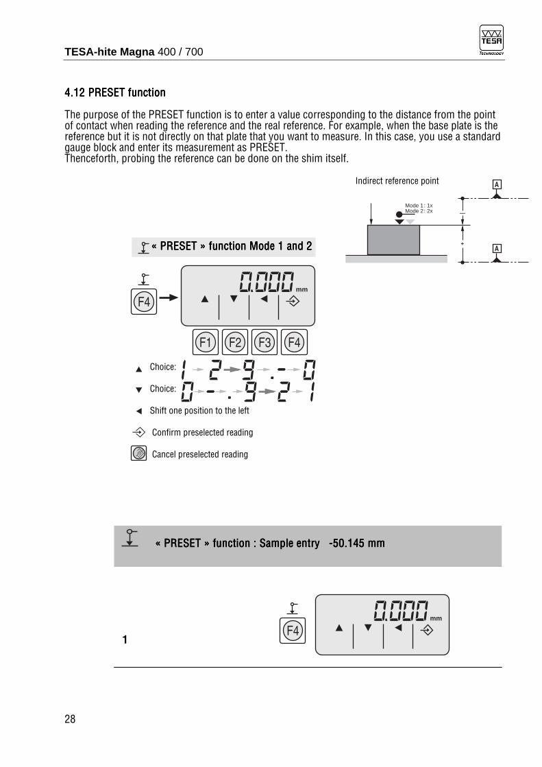
4444....12121212 PRESETPRESETPRESETPRESET functionfunctionfunctionfunction
The purpose of the PRESET function is to enter a value corresponding to the distance from the point of contact when reading the reference and the real reference. For example, when the base plate is the reference but it is not directly on that plate that you want to measure. In this case, you use a standard gauge block and enter its measurement as PRESET. Thenceforth, probing the reference can be done on the shim itself. Indirect reference point «««« PRESETPRESETPRESETPRESET »»»» functionfunctionfunctionfunction Mode 1 and Mode 1 and Mode 1 and Mode 1 and 2 2 2 2 Choice: Choice: Shift one position to the left Confirm preselected reading Cancel preselected reading
1
«««« PRESETPRESETPRESETPRESET »»»» functionfunctionfunctionfunction : : : : SampleSampleSampleSample entry entry entry entry ----50.145 mm50.145 mm50.145 mm50.145 mm

TESA-hite Magna 400 / 700
29
2 x
mm
1 x 5 x
mm
1 x
mm
2 x1 x
mm
1 x1 x
mm
4 x1 x
mm
5 x1 x
mm
2 3 4 5 6 7 8

TESA-hite Magna 400 / 700
30
mm
mm
mm
mm
mm
mm
9 IMPORTANTIMPORTANTIMPORTANTIMPORTANT Each time a new reference is requested the remains in memory Deleting «««« PRESETPRESETPRESETPRESET »»»» Two possibilities: AAAA BBBB
«««« PRESEPRESEPRESEPRESETTTT »»»» functionfunctionfunctionfunction : : : : CancellationCancellationCancellationCancellation

TESA-hite Magna 400 / 700
31
mm
mm
mm
Access and entry of «««« PRESETPRESETPRESETPRESET »»»» As for Modes 1 and 2
«««« PRESETPRESETPRESETPRESET »»»» functionfunctionfunctionfunction : : : : Mode 3Mode 3Mode 3Mode 3

TESA-hite Magna 400 / 700
32
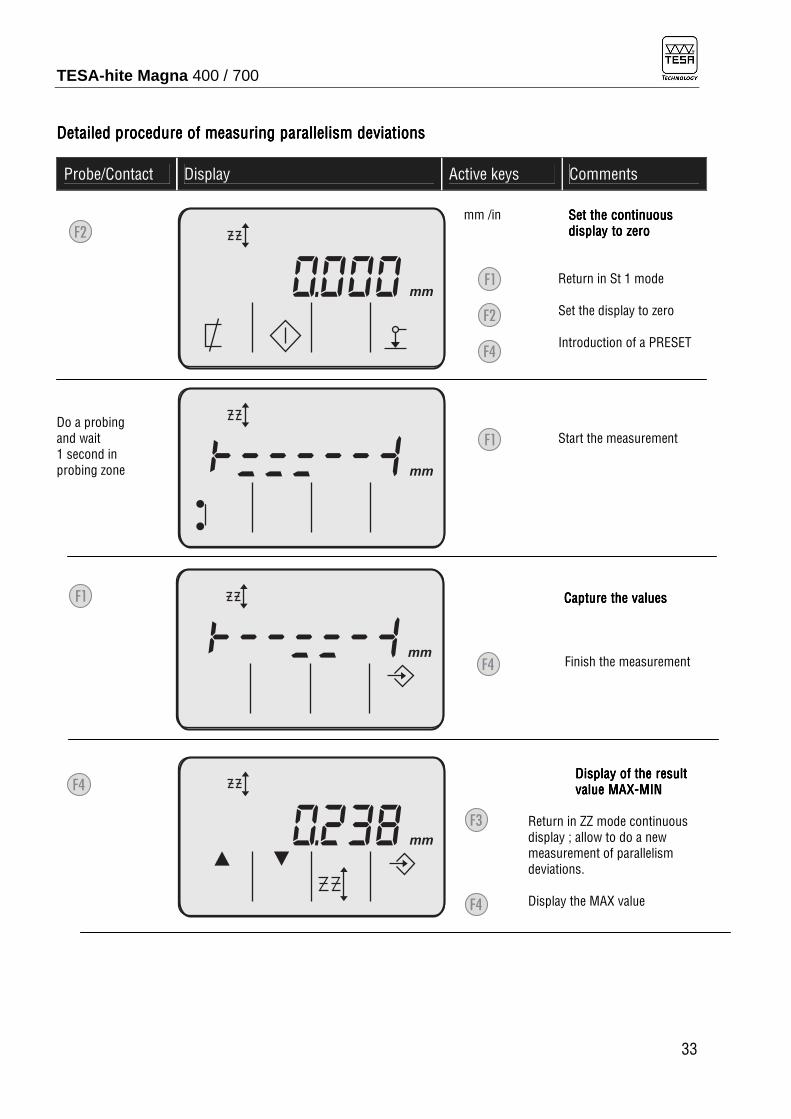
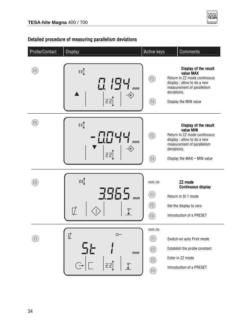
4444....13131313 MeMeMeMeasuring parallelisasuring parallelisasuring parallelisasuring parallelism deviationsm deviationsm deviationsm deviations
The measurement of the parallelism deviations is carried out in ZZ measuring mode. Place the gauge head in front of the surface to be controlled, do the probing and wait about 1 second in the probing zone. A bar graph appears and the measurement can be started by means of the F1 key and will be ended by means of the F4 key. Detailed procedDetailed procedDetailed procedDetailed procedure of measuring parallelism deviationsure of measuring parallelism deviationsure of measuring parallelism deviationsure of measuring parallelism deviations
Probe/Contact Display Active keys Comments
mm /in Switch-on auto Print mode Establish the probe constant Enter in ZZ mode Introduction of a PRESET mm /in ZZZZZZZZ mode mode mode mode Continuous displayContinuous displayContinuous displayContinuous display Return in St 1 mode Set the display to zero Introduction of a PRESET
mm
mm
Deviation:«maximum negative»
«maximum positive»
Starting point 0 Parallelism error
TESA-hite Magna 400 / 700
33
Detailed procedDetailed procedDetailed procedDetailed procedure of measuring parallelism deviationsure of measuring parallelism deviationsure of measuring parallelism deviationsure of measuring parallelism deviations
Probe/Contact Display Active keys Comments
mm /in SSSSet the continuouset the continuouset the continuouset the continuous display to zerodisplay to zerodisplay to zerodisplay to zero Return in St 1 mode Set the display to zero Introduction of a PRESET Do a probing and wait Start the measurement 1 second in probing zone CaptureCaptureCaptureCapture the values the values the values the values Finish the measurement Display of the Display of the Display of the Display of the resultresultresultresult value value value value MAXMAXMAXMAX----MINMINMINMIN Return in ZZ mode continuous display ; allow to do a new measurement of parallelism deviations. Display the MAX value
mm
mm
mm
mm
TESA-hite Magna 400 / 700
34
Detailed procedDetailed procedDetailed procedDetailed procedure of measuring parallelism deviationsure of measuring parallelism deviationsure of measuring parallelism deviationsure of measuring parallelism deviations
Probe/Contact Display Active keys Comments
Display of the Display of the Display of the Display of the resultresultresultresult value value value value MAXMAXMAXMAX Return in ZZ mode continuous display ; allow to do a new measurement of parallelism deviations. Display the MIN value Display of the Display of the Display of the Display of the resultresultresultresult valvalvalvaluuuueeee MIN MIN MIN MIN Return in ZZ mode continuous display ; allow to do a new measurement of parallelism deviations. Display the MAX – MIN value mm /in ZZ ZZ ZZ ZZ mode mode mode mode Continuous displayContinuous displayContinuous displayContinuous display Return in St 1 mode Set the display to zero Introduction of a PRESET mm /in Switch-on auto Print mode Establish the probe constant Enter in ZZ mode Introduction of a PRESET
mm
mm
mm
mm

TESA-hite Magna 400 / 700
35
4444....14141414 UUUUse of the fine adjustmentse of the fine adjustmentse of the fine adjustmentse of the fine adjustment
The fine adjustment is used when one wants to precisely adjust a height in 3 «ZZ» mode. It can also be used when seeking the culmination point of a bore or a shaft. Indeed, in such a case, the probing force can be very finely adjusted affording great stability. 10 Lightly block the light greylight greylight greylight grey knurled screw 9 Pull and turn the dark greydark greydark greydark grey knurled screw
5 INSTRUMENT CONFIGURATION
To enter into the configuration mode, you have to activate by turned on the instrument, first the F1, then simultaneously the F1 and ON/OFF keys; after deactivate the ON/OFF and then the F1 key. The configuration menu allows the following functions:
- F1: Activates or deactivates the Beep, when probing or detecting the culmination point. By default the Beep strong is active (BEEP Hi).
- F2: By default the TESA-Hite Magna 400 / 700 turns off after 20 min (AUTO OF). To turn it off only with the ON/OFF button, set this option on ON.
- F3: Change the resolution of the instrument (0.001 / 0.005 / 0.01 mm). By default the resolution is 0.001 mm.

TESA-hite Magna 400 / 700
36
mm
mm
Detailed procedDetailed procedDetailed procedDetailed procedure of the instrument configuration menuure of the instrument configuration menuure of the instrument configuration menuure of the instrument configuration menu
Probe/Contact Display Active keys Comments
mm /in and simultaneously Activates or deactivates the Beep Automatic turn off or not Change the resolution Exit of the configuration menu Activates the Beep Lo Return to the configuration menu Deactivates the Beep Return to the configuration menu Activates the Beep Hi Return to the configuration menu
mm /in Activates or deactivates the Beep Automatic turn off or not Change the resolution Exit of the configuration menu
mm
mm
mm

TESA-hite Magna 400 / 700
37
mm
mm
Detailed procedDetailed procedDetailed procedDetailed procedure of the instrument configuration menuure of the instrument configuration menuure of the instrument configuration menuure of the instrument configuration menu
Probe/Contact Display Active keys Comments
Turn off only with the ON/OFF button Return to the configuration menu Automatic turn off Return to the configuration menu mm /in Activates or deactivates the Beep Automatic turn off or not Change the resolution Exit of the configuration menu mm /in Change the resolution Exit of the configuration menu
mm
mm
mm

TESA-hite Magna 400 / 700
38
Detailed procedDetailed procedDetailed procedDetailed procedure of the instrument configuration menuure of the instrument configuration menuure of the instrument configuration menuure of the instrument configuration menu
Probe/Contact Display Active keys Comments
mm /in Change the resolution Exit of the configuration menu mm /in Change the resolution Exit of the configuration menu mm /in Change the resolution Exit of the configuration menu mm /in Change the resolution Exit of the configuration menu
mm
mm
mm
in

TESA-hite Magna 400 / 700
39
mm
Detailed procedDetailed procedDetailed procedDetailed procedure of the instrument configuration menuure of the instrument configuration menuure of the instrument configuration menuure of the instrument configuration menu
Probe/Contact Display Active keys Comments
mm /in Change the resolution Exit of the configuration menu mm /in Activates or deactivates the Beep Automatic turn off or not Change the resolution Exit of the configuration menu Then, to enter into the measuring mode, moves slowly the measuring carriage to pass the reference mark. For more detailed information, please consult chapter 2.2
mm
mm

TESA-hite Magna 400 / 700
40
6 ERROR MESSAGES
The error messages can be erased by pressing the key or by turning off the instrument using the key
- The message Error 4Error 4Error 4Error 4 indicates in problem in the measuring system, sensor or scale. It can also be caused by moving the measuring head to fast.
- The messages Error 6Error 6Error 6Error 6 and Error 9Error 9Error 9Error 9 indicate a fault in the electronic system. - The acoustic message Beep ErrorBeep ErrorBeep ErrorBeep Error detects a probe effected too brusquely. - If an error message persists, send the instrument to your TESA after-sales service agent.
7 MAINTENANCE
7.1 7.1 7.1 7.1 CleaningCleaningCleaningCleaning
The TESA-Hite Magna 400 / 700 must be used in a place that complies with the extreme operating and storage conditions indicated in the technical data. The magnetic measuring system does not require particular maintenance; however to clean the TESA-Hite Magna 400 / 700, use exclusively a dry, lint-free cloth. Do not use aggressive solvents. WarningWarningWarningWarning The cleaning of the guides and the magnetic rule is a delicate operation; we consequently recommend that you proceed with the utmost caution. PrePrePrePreparationparationparationparation Remove the housing by unscrewing the 3 screws located on the top of the base. Cleaning thCleaning thCleaning thCleaning the guidese guidese guidese guides Clean the guide rails Fig. 3 with a lint-free Guide rails cloth and relubricate the guide rails with watch oil. Cleaning the glass ruleCleaning the glass ruleCleaning the glass ruleCleaning the glass rule Clean the magnetic rule, Fig. 3, with a lint-free cloth, possibility slightly Magnetic rule moistened with alcohol (do not use other solvents) Fig. 3

TESA-hite Magna 400 / 700
41
7.2 7.2 7.2 7.2 ChaChaChaCharging the batteryrging the batteryrging the batteryrging the battery
First of all, you should know that new batteries or batteries that are not used for a long period of time only attain their full performance after 30 to 40 charges. Fully recharging the battery pack with the mains adaptor N° 04761054 requires about 8 hours. The TESA-Hite Magna 400 / 700 can then be used for about 60 hours. If the battery charge is not sufficient (under 5,8 V), the battery symbol appears on the display. The operator can continue with the measurements for about 15 minutes. Once this time has gone, the operating function will deteriorate. For charging batteries, use only the original adaptor N° 04761054 and proceed as follows: – Connect mains adaptor to the socket located on the back of the TESA-Hite Magna 400 / 700. – Connect adaptor to the mains 110 to 240 Vac / 50 to 60 Hz with connecting cable supplied. – Complete charging takes about 8 hours. – After full recharging, the adaptor may remain connected to the mains up to max. 24 hours without danger to the battery. – During the recharging it is still possible to use the instrument; the time necessary for the recharge will simply be longer. NoteNoteNoteNote Unused batteries will gradually lose charge as time goes by and, if not recharged, deteriorate. They must therefore be charged at intervals which do not exceed 6 months.
8 DELIVERY PROGRAMME
The order numbers are the following: TESA-Hite Magna 400 00730047 TESA-Hite Magna 700 00730059 Each TESA-Hite Magna is supplied with the following standard accessories: - 1 Standard insert holder 00760143 - 1 Standard measuring insert with a 5 mm tungsten carbide ball tip 00760164 - 1 Master piece with nominal dimension 6.350 mm / 0.250 in 00760231 - 1 Rechargeable 6V battery 00760157 - 1 Mains adaptor 110 to 240 Vac / 50 to 60 Hz 04761054 - 1 Cable EU 04761055 - 1 Cable US 04761056 - 1 SCS calibration certificate - 1 Instruction manual with a declaration of conformity - 1 Shipping box

TESA-hite Magna 400 / 700
42
00760007600076000760231231231231 00760164007601640076016400760164 00760143007601430076014300760143
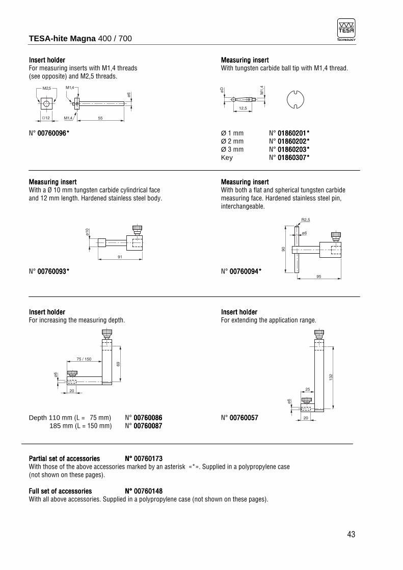
8.1 8.1 8.1 8.1 Optional accessoriesOptional accessoriesOptional accessoriesOptional accessories
All insert holder and measuring insert from MICRO-HITE can be used with the TESA-Hite Magna. Measuring insertMeasuring insertMeasuring insertMeasuring insert Measuring insertMeasuring insertMeasuring insertMeasuring insert With tungsten carbide ball tip, Ø 10 mm. With tungsten carbide ball tip, Ø 3 mm. N° 00760060*00760060*00760060*00760060* N° 00760061*00760061*00760061*00760061* Measuring insertMeasuring insertMeasuring insertMeasuring insert Measuring insertMeasuring insertMeasuring insertMeasuring insert With tungsten carbide measuring face (convex), With disc-shaped, tungsten carbide measuring for inspecting cylindrical bores or establishing face for measuring grooves, turned grooves, internal thread position (metric or similar). centring shoulders, etc. D= 2,2 mm for M3 to M16 N° 00760066007600660076006600760066 E = 1 mm / Ø 4,5 mm N° 00760074007600740076007400760074 D= 4,5 mm for M6 to M48 N° 00760067007600670076006700760067 E = 2 mm / Ø 14 mm N° 00760075007600750076007500760075**** D= 9,7 mm for M12 to M150 N° 00760068007600680076006800760068 E = 3 mm / Ø 19 mm N° 00760076007600760076007600760076 Measuring insertMeasuring insertMeasuring insertMeasuring insert IndexIndexIndexIndexinginginging of the of the of the of the insert insert insert insert holder holder holder holder With small tungsten carbide measuring face, Ø 2 mm, To screw on the mounting pin N° 00760082007600820076008200760082 N° 00000760225076022507602250760225
73
ø6
23
32
ø1
4,5
22
52
ø6
ø5
ø6
55
ø10
ø6
55
ø3
55
øD
ø6
ø4
ø2
6 9
E
55
ø9
,7
ø6
ø4
ø2
8 20
ø2
,2
ø4
,5
ø6
4
ø2
55
TESA-hite Magna 400 / 700
43
Insert Insert Insert Insert holderholderholderholder Measuring insertMeasuring insertMeasuring insertMeasuring insert For measuring inserts with M1,4 threads With tungsten carbide ball tip with M1,4 thread. (see opposite) and M2,5 threads. N° 00760096*00760096*00760096*00760096* Ø 1 mm N° 01860201*01860201*01860201*01860201* Ø 2 mm N° 00001860202186020218602021860202**** Ø 3 mm N° 01860203*01860203*01860203*01860203* Key N° 01860307*01860307*01860307*01860307* Measuring insertMeasuring insertMeasuring insertMeasuring insert Measuring insertMeasuring insertMeasuring insertMeasuring insert With a Ø 10 mm tungsten carbide cylindrical face With both a flat and spherical tungsten carbide and 12 mm length. Hardened stainless steel body. measuring face. Hardened stainless steel pin, interchangeable. N° 00760093*00760093*00760093*00760093* N° 00760094*00760094*00760094*00760094* Insert Insert Insert Insert holderholderholderholder Insert Insert Insert Insert holderholderholderholder For increasing the measuring depth. For extending the application range. Depth 110 mm (L = 75 mm) N° 00760000760000760000760088886666 N° 00000760007600076000760057575757 185 mm (L = 150 mm) N° 00000760007600076000760087878787 Partial set of accessoriesPartial set of accessoriesPartial set of accessoriesPartial set of accessories NNNN°°°° 00760173007601730076017300760173 With those of the above accessories marked by an asterisk «*». Supplied in a polypropylene case (not shown on these pages). Full set of accessorFull set of accessorFull set of accessorFull set of accessoriesiesiesies NNNN°°°° 00760148007601480076014800760148 With all above accessories. Supplied in a polypropylene case (not shown on these pages).
ø6
55M1,4
M2,5 M1,4
12
12,5
M1,4
øD
90
95
ø6
R2,5
ø1
0
91
ø6
25
13
2
20
ø6
75 / 150
69
20

TESA-hite Magna 400 / 700
44
Holder for dial test indicatorHolder for dial test indicatorHolder for dial test indicatorHolder for dial test indicator NNNN° ° ° ° 00760222007602220076022200760222 Probe insert setProbe insert setProbe insert setProbe insert set N° 00760175N° 00760175N° 00760175N° 00760175 Composition of the set: Supplied in a suited plastic case. 1 1 1 1 Insert holderInsert holderInsert holderInsert holder N° 00760177 1 1 1 1 Probing pinProbing pinProbing pinProbing pin
In hardened steel for grooves, 00760177 centring shoulders, blind bores, etc. Tilted through 8° N° 00760178
1 1 1 1 Probing pinProbing pinProbing pinProbing pin In hardened steel, shouldered, for depth measurement N° 00760179 3 3 3 3 Measuring insertsMeasuring insertsMeasuring insertsMeasuring inserts With a hardened ball tip, Ø 0.9 mm N° 00760180 Ø 1.9 mm N° 00760181 Ø 2.9 mm N° 00760182 1 Measuring i1 Measuring i1 Measuring i1 Measuring insertnsertnsertnsert With a Ø 8 mm cone-shaped measuring face in hardened steel N° 00760183 2 Extension2 Extension2 Extension2 Extensionssss Length 20 mm, thread M3 to M3 N° 00760184 Length 20 mm, thread M3 to M2,5 N° 00760185 00760178 00760179 00760180 00760181 00760182 00760183 00760184/5 TESA PRINTER SPCTESA PRINTER SPCTESA PRINTER SPCTESA PRINTER SPC N° 0N° 0N° 0N° 06430000643000064300006430000 Supplied with: 1 Roll heat sensitive paper N° 04765013 1 Mains adaptor, 100 to 240 Vac / 50 to 60 Hz, 6,6 Vdc / 750 mA N° 04761054 1 Cable EU N° 04761055 1 Instruction manual with declaration of conformity
ø6
73
20
2525
40
28
ø8
M3
25
8
ø4
20
45
ø6
ø4
M3 M
3
M3
4,5
8°
8°
78
ø4
8°
3
1,5
0,5
76
ø4
ø1,2
16
26,6
ø0,9
M3
23,1
26,6
ø1,9
M3
22,6
26,6
ø2,9
M3
22,1
23
ø4
M3
20
M

TESA-hite Magna 400 / 700
45
OPTIONAL OPTIONAL OPTIONAL OPTIONAL ACACACACCESSOCESSOCESSOCESSORRRRIIIIESESESES CCCConnection cableonnection cableonnection cableonnection cable RS232, opto-coupled with 9 pin m/f connector, length 2 m N° 04761052N° 04761052N° 04761052N° 04761052 PPPPrrrractice workpieceactice workpieceactice workpieceactice workpiece N° 00760124N° 00760124N° 00760124N° 00760124
9 TECHNICAL DATA
CCCCHHHHARACTERISTIARACTERISTIARACTERISTIARACTERISTICCCCSSSS TESATESATESATESA----Hite Hite Hite Hite Magna 400Magna 400Magna 400Magna 400 TESATESATESATESA----HiteHiteHiteHite Magna Magna Magna Magna 700 700 700 700 Measuring span 415 mm / 16 in 715 mm / 28 in Application range with standard insert holder 00760143 570 mm / 22 in 870 mm / 34 in with insert holder 00760057 625 mm / 24 in 925 mm / 36 in with insert holder S07001622 795 mm / 31 in 1095 mm / 43 in Maximum permissible error* 8 µm / 0.0003 in Repeatability* on flat surface: 2s=<3µm / 2s=< 0.00015in within bores: 2s=<5m / 2s=< 0.00020in Maximum perpendicularity error (frontal) ---- Display liquid crystal display (LCD) Display size 83 x 49 mm Resolution 0.001/0.005/0.01 mm – .0001/.0002/.001 in Number of decades 7 plus minus sign Character size 12 mm Additional display symbols for the functions Instrument base grey cast iron with rectified sole Guidance across the reference surface through mechanical contact Material measure magnetic scale Coefficient of linear expansion 12±1.5 10-6 K-1
Measuring head Guiding on ball-bearings Head displacement with a handwheel Maximum perm. displacement speed 1 m/s Value capture automatic Force exerted by measuring head when taking readings 1.5N ±0.5N (acoustic signal) Keypad 8 keys for selecting the functions and entering the values Air cushion no Power supply 6V rechargeable battery Autonomy 60 hours, recharging time 8 hours Data output RS-232 Measuring head lock yes Fine adjustment yes Operating temperature range 10°C to 40°C Storage temperature range -10°C to 60°C Maximum relative humidity 100% Weight 14 kg 16 kg Degree of protection IP55 (Electronic box and measuring system: IP65) Electromagnetic compatibility EN 50081-1, EN 50081-2 With mains adaptor disconnected EN 50082-1, EN 50082-2 Marked with individual identification number * Valid with standard accessories
241
148 100

TESA-hite Magna 400 / 700
46
9.1 Description 9.1 Description 9.1 Description 9.1 Description of theof theof theof the RS 232 RS 232 RS 232 RS 232 interface interface interface interface
To link the TESA-Hite Magna 400 / 700 to a Printer SPC or a PC, use the cable 04761052. Transmission speed 4800 bauds Character length 7 bits Start 1 bit Stop 2 bits Parity even
9.9.9.9.1.11.11.11.1 MonodMonodMonodMonodirectional data transmissionirectional data transmissionirectional data transmissionirectional data transmission
The data transfer is done by activating the function key .
TraTraTraTransfernsfernsfernsfer mm ±9999.999(9) <cr/lf> In ±99.99999 <cr/lf>
9.1.2 9.1.2 9.1.2 9.1.2 Bidirectional data transmissionBidirectional data transmissionBidirectional data transmissionBidirectional data transmission
This transmission mode allows direct control of the height gauge from a PC. Given instructions are as follows: Each command must be ended using ASCII code «CR» ?<cr> Measured value ID ?<cr> Product identification number TE…<cr/lf> VER ?<cr> Instrument version 2.1<cr/lf> UNI ?<cr> Unit system MM ou IN<cr/lf> MM<cr> Work in metric (mm) <cr/lf> IN<cr> Work in inch (in) <cr/lf> The pin assignment on the 9 pin (female) connector is as follow: Control panel PC 2 TXD (Data Out) 2 RXD 3 RXD (Data Req) 3 TXD 5 GND Other pins are leaved unused8 GARANTIE
10 WARRANTY
We guarantee this product against any fault of design, manufacture or material for a period of 12 months from the date of purchase. Any repair work carried out under the guarantee conditions is free of charge. Our responsibility is limited to the repair of the product or, if we consider it necessary, to its free replacement. The following are not covered by our guarantee: batteries and damages due to incorrect handling, failure to observe the instruction manual, or attempts by any non-qualified party to repair the product; any consequences whatever which may be connected either directly or indirectly with the product supplied or its use. (Extract from our General Terms of Delivery, December 1, 1981).
5 GND
V + (DTR)
Data In (TXD)
Data Out (RXD)
1
9
V � (RTS)
6
Printer SPC or PC sideSub-D 9 pole male

TESA-hite Magna 400 / 700
47
11 DECLARATION OF CONFORMITY
We thank you very much for your confidence in purchasing this product. We hereby certify that it was inspected in our works. Declaration of conformity and confirmation of traceability of the indicated valuesDeclaration of conformity and confirmation of traceability of the indicated valuesDeclaration of conformity and confirmation of traceability of the indicated valuesDeclaration of conformity and confirmation of traceability of the indicated values We declare under our sole responsibility that this product is in conformity with all technical data as specified in our sales literature (instruction manual, leaflet, general catalogue). In addition, we certify that the measuring equipment used to check this product refers to national reference standards. Traceability of the measured values is ensured by our Quality Assurance. Name of manufacturerName of manufacturerName of manufacturerName of manufacturer TESA SA AAAAdddddress of manufacturerdress of manufacturerdress of manufacturerdress of manufacturer TESA SA Rue du Bugnon 38 CH-1020 Renens (Switzerland) We declare that the following productWe declare that the following productWe declare that the following productWe declare that the following product(s)(s)(s)(s) Name of productName of productName of productName of product TESA-Hite Magna 400 / 700 Type of productType of productType of productType of product 00730047 / 00730059 is (are) in is (are) in is (are) in is (are) in conformity with the provisions of the European directiveconformity with the provisions of the European directiveconformity with the provisions of the European directiveconformity with the provisions of the European directive 2004/108/CE And And And And is (are) in is (are) in is (are) in is (are) in conformity with the provisions of the European Standardsconformity with the provisions of the European Standardsconformity with the provisions of the European Standardsconformity with the provisions of the European Standards EN 61326-1 Renens, the 22.02.2010 Manager of Quality Assurance.

TESA-hite Magna 400 / 700
48
NOTES