Embed Size (px)
DESCRIPTION
MDS Installation. Contents. Introduction Outdoor Unit Installation Indoor Unit Installation Refrigerant Pipe Work Gas Charge Wiring Summary. Introduction. Bad installation – System will not operate as per design Waste of Money Waste of Time Bad Image 3 Major Categories - PowerPoint PPT Presentation
Citation preview

Page 1
MDS InstallationMDS Installation

Page 2
Contents
IntroductionIntroduction
Outdoor Unit Installation Outdoor Unit Installation
Indoor Unit InstallationIndoor Unit Installation
Refrigerant Pipe WorkRefrigerant Pipe Work
Gas ChargeGas Charge
WiringWiring
SummarySummary

Page 3
Introduction

Page 4
Bad installation – System will not operate as per design
Waste of Money Waste of Time Bad Image
3 Major Categories Unit Installation Piping Installation Wiring Installation
INSTALLATIONINSTALLATION

Page 5
Outdoor Unit Installation

Page 6
Outdoor Unit Installation
Sufficient area around the unit. No barrier for supply air and discharge air.
Avoid discharge air return to the unit (Hot Air short-circuiting)
Strong foundation for the unit
Outdoor Unit InstallationOutdoor Unit Installation

Page 7
Handling Outdoor Unit
Correct
Outdoor Unit InstallationOutdoor Unit Installation

Page 8
Handling Outdoor Unit
Wrong
Outdoor Unit InstallationOutdoor Unit Installation

Page 9
Correct Wrong
Outdoor Unit InstallationOutdoor Unit Installation

Page 10
Outdoor Unit InstallationOutdoor Unit Installation

Page 11
Wall / Barrier higher than unit
Side View
Wall / Barrier lower than unit
Outdoor Unit InstallationOutdoor Unit Installation
Outdoor Unit Spacing (Single Unit)

Page 12
Top View (Barrier higher than unit)
Outdoor Unit Spacing (Single Unit)
Outdoor Unit InstallationOutdoor Unit Installation

Page 13
Top View (Barrier lower than unit)
Outdoor Unit InstallationOutdoor Unit Installation
Outdoor Unit Spacing (Single Unit)

Page 14
Outdoor Unit Spacing (More than 1 unit)
Top View
(Wall / Barrier restriction same as 1 outdoor unit)
Outdoor Unit InstallationOutdoor Unit Installation

Page 15
Outdoor Unit Spacing (More than 1 unit)
Top View
(Wall / Barrier restriction same as 1 outdoor unit)
Outdoor Unit InstallationOutdoor Unit Installation

Page 16
Top View
(Wall / Barrier restriction same as 1 outdoor unit)
Outdoor Unit Spacing (More than 1 unit)
Outdoor Unit InstallationOutdoor Unit Installation

Page 17
Outdoor Unit InstallationOutdoor Unit Installation
Outdoor Unit Foundation
Floor location strength
- Able to withstand the unit weight and vibration
Page 18
Outdoor Unit InstallationOutdoor Unit Installation
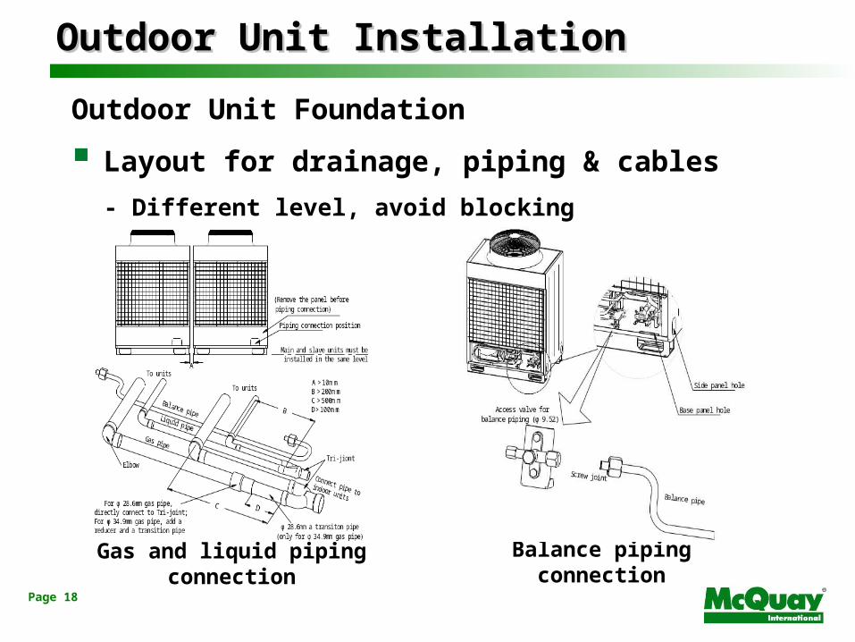
Outdoor Unit Foundation
Layout for drainage, piping & cables
- Different level, avoid blocking
Gas and liquid piping connection Balance piping connection

Page 19
Outdoor Unit InstallationOutdoor Unit Installation
Outdoor Unit Foundation
Screw bolt required to further tighten the unit
- Avoid the unit from falling due to earthquake

Page 20
Indoor Unit Installation

Page 21
Indoor Unit InstallationIndoor Unit Installation
Drainage Pipe Work
Adjust the downward gradient
Gradient of 1:100 or more

Page 22
Indoor Unit InstallationIndoor Unit Installation
Drainage Pipe Work
Group drain pipe
≥100mm
Vent opening Clamp of drain pipe
Gradient ≥ 1/100
Converged drain pipe

Page 23
Indoor Unit InstallationIndoor Unit Installation
EXV Box Installation
MUST install vertically upward

Page 24
Unit and EXV Selection - 2006
Indoor Mode R22 R410A R22 R410AWMD 09G 1/4 1/4WMD 10G 1/4 1/4WMD 15G 1/4 1/4WMD 20G 1/4 1/4WMD 25G 3/8 1/4 MEX-20-3SAP-B MEX-20-2SAP-B
CKD 10C 1/4 1/4CKD 15C 1/4 1/4CKD 20C 1/4 1/4
CKD 20A 1/4 1/4CKD 25A 3/8 1/4 MEX-20-3SAP-A MEX-20-2SAP-ACKD 30A 3/8 3/8 MEX-25-3SAP-A MEX-20-3SAP-ACKD 40A 3/8 3/8 MEX-25-3SAP-A MEX-20-3SAP-ACKD 50A 3/8 3/8 MEX-25-3SAP-A MEX-20-3SAP-A
MEX-20-2SAP-A
MEX-16-2SAP-AMEX-16-2SAP-A
MEX-20-2SAP-B
MEX-20-2SAP-A
Liquid Pipe Diamter (Inch) MEX Model
MEX-16-2SAP-BMEX-16-2SAP-BMEX-16-2SAP-B

Page 25
Unit and EXV Selection - 2006
Indoor Mode R22 R410A R22 R410ACCD 10C 1/4 1/4CCD 15C 1/4 1/4CCD 20C 1/4 1/4CCD 25C 3/8 1/4 MEX-20-3SAP-A MEX-20-2SAP-ACCD 28C - 3/8 - MEX-20-3SAP-ACCD 30C 3/8 3/8 MEX-25-3SAP-A MEX-20-3SAP-ACCD 38C - 3/8 - MEX-20-3SAP-ACCD 40C 3/8 3/8 MEX-25-3SAP-A MEX-20-3SAP-ACCD 50C 3/8 3/8 MEX-25-3SAP-A MEX-20-3SAP-ACCD 60C 1/2 3/8 MEX-25-3SAP-A MEX-25-3SAP-A
CED 15E - 1/4 - MEX-16-2SAP-ACED 20E 1/4 1/4 MEX-20-2SAP-A MEX-16-2SAP-ACED 25E 3/8 1/4 MEX-20-3SAP-A MEX-16-2SAP-ACED 28E 3/8 3/8 MEX-20-3SAP-A MEX-20-3SAP-A
CED 40D 3/8 3/8 MEX-25-3SAP-A MEX-20-3SAP-ACED 50D 3/8 3/8 MEX-25-3SAP-A MEX-20-3SAP-ACED 62C 1/2 3/8 MEX-25-3SAP-A MEX-25-3SAP-A
MEX-20-2SAP-A
Liquid Pipe Diamter (Inch) MEX Model
MEX-16-2SAP-AMEX-16-2SAP-A

Page 26
Indoor Mode R22 R410A R22 R410AWMD 09G 1/4 1/4WMD 10G 1/4 1/4WMD 15G 1/4 1/4WMD 20G 1/4 1/4 MEX-18-2SAP-D MEX-18-2SAP-DWMD 25G 3/8 1/4 MEX-18-3SAP-D MEX-22-2SAP-D
CKD 10C 1/4 1/4CKD 15C 1/4 1/4CKD 20C 1/4 1/4 MEX-18-2SAP-C MEX-18-2SAP-C
CKD 20A 1/4 1/4 MEX-18-2SAP-C MEX-22-2SAP-CCKD 25A 3/8 1/4 MEX-18-3SAP-C MEX-22-2SAP-CCKD 30A 3/8 3/8 MEX-24-3SAP-C MEX-22-3SAP-CCKD 40A 3/8 3/8 MEX-24-3SAP-C MEX-22-3SAP-CCKD 50A 3/8 3/8 MEX-24-3SAP-C MEX-22-3SAP-C
MEX-15-2SAP-CMEX-15-2SAP-C
MEX-15-2SAP-DMEX-15-2SAP-DMEX-15-2SAP-D
Liquid Pipe Diamter (Inch) MEX Model
Unit and EXV Selection - New
Marketing Bulletin: MBM001-0801

Page 27
Indoor Mode R22 R410A R22 R410ACCD 10C 1/4 1/4CCD 15C 1/4 1/4CCD 20C 1/4 1/4 MEX-18-2SAP-C MEX-18-2SAP-CCCD 25C 3/8 1/4 MEX-18-3SAP-C MEX-22-2SAP-CCCD 28C - 3/8 - MEX-22-3SAP-CCCD 30C 3/8 3/8 MEX-24-3SAP-C MEX-22-3SAP-CCCD 38C - 3/8 - MEX-22-3SAP-CCCD 40C 3/8 3/8 MEX-24-3SAP-C MEX-22-3SAP-CCCD 50C 3/8 3/8 MEX-24-3SAP-C MEX-22-3SAP-CCCD 60C 1/2 3/8 MEX-24-4SAP-C MEX-24-3SAP-C
CED 15E - 1/4 - MEX-15-2SAP-CCED 20E 1/4 1/4 MEX-18-2SAP-C MEX-18-2SAP-CCED 25E 3/8 1/4 MEX-18-3SAP-C MEX-22-2SAP-CCED 28E 3/8 3/8 MEX-18-3SAP-C MEX-22-3SAP-C
CED 40D 3/8 3/8 MEX-24-3SAP-C MEX-22-3SAP-CCED 50D 3/8 3/8 MEX-24-3SAP-C MEX-22-3SAP-CCED 62C 1/2 3/8 MEX-24-4SAP-C MEX-24-3SAP-C
MEX Model
MEX-15-2SAP-CMEX-15-2SAP-C
Liquid Pipe Diamter (Inch)
Unit and EXV Selection - New
Marketing Bulletin: MBM001-0801
Page 28
Indoor Unit InstallationIndoor Unit Installation
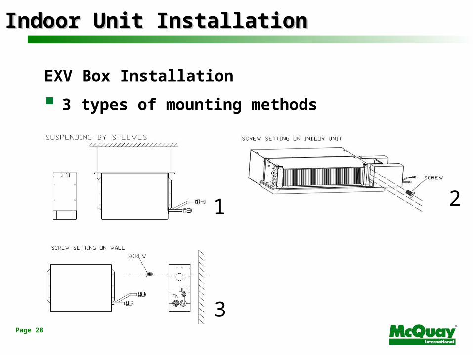
EXV Box Installation
3 types of mounting methods
1 2
3

Page 29
Indoor Unit InstallationIndoor Unit Installation
EXV Box Installation

Page 30
Indoor Unit InstallationIndoor Unit Installation
EXV Box Installation

Page 31
Refrigeration Pipe Work

Page 32
Refrigerant Pipe WorkRefrigerant Pipe Work
Piping Installation
Ensure piping is dry, clean and no air leakage

Page 33
Refrigerant Pipe WorkRefrigerant Pipe Work
Piping Installation
Nitrogen gas replacement
Nitrogen gas pressure: about 0.02 MPa (0.2 kg/cm2, 2.8 psi)

Page 34
Refrigerant Pipe WorkRefrigerant Pipe Work
Piping Installation
Covering of refrigerant pipes
- Prevent water, dirt or dust from getting into the pipes
Pinching
Taping Method

Page 35
Refrigerant Pipe WorkRefrigerant Pipe Work
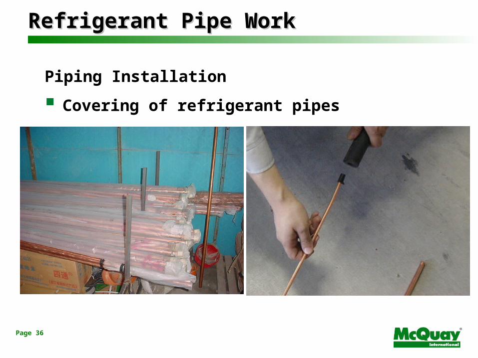
Piping Installation
Covering of refrigerant pipes
Page 36
Refrigerant Pipe WorkRefrigerant Pipe Work
Piping Installation
Covering of refrigerant pipes
Page 37
Refrigerant Pipe WorkRefrigerant Pipe Work
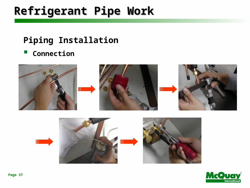
Piping Installation
Connection

Page 38
Refrigerant Pipe WorkRefrigerant Pipe Work
Piping Installation
Refnet & distributors joints to be install horizontally
In ±15°
In ±15°

Page 39
Refrigerant Pipe WorkRefrigerant Pipe Work
Piping Installation
Refnet & distributors joints to be install horizontally

Page 40
Connection Type of Refnet Joint/Distributors
Refnet Joint
Refrigerant Pipe WorkRefrigerant Pipe Work

Page 41
Connection Type of Refnet Joint/Distributor
Distributor
Refrigerant Pipe WorkRefrigerant Pipe Work

Page 42
Connection Type of Refnet Joint/Distributors
Refnet Joint Distributor
Refrigerant Pipe WorkRefrigerant Pipe Work

Page 43
Connection Type of Refnet Joint/Distributors
Refnet Joint Distributor
Refrigerant Pipe WorkRefrigerant Pipe Work

Page 44
Refrigerant Pipe WorkRefrigerant Pipe Work
Thermal Insulation Work
Insulation material must be able to withstand the pipe heat
- Heat pump unit – heat resistance polyethylene foamed (> 120°C)
- Cooling only unit – polyethylene (> 100°C)
Insulation method
Thickness of insulation

Page 45
Refrigerant Pipe WorkRefrigerant Pipe Work
Thermal Insulation Work
Both liquid and gas pipe MUST be insulated
Gas pipe
Liquid pipe
Insulation
Control wire
Finishing tape

Page 46
Refrigerant Pipe WorkRefrigerant Pipe Work
Thermal Insulation Work
Wrong Method Correct Method

Page 47
Refrigerant Pipe WorkRefrigerant Pipe Work
Thermal Insulation Work
Insulation thickness
Notes:• Hot and wet environment, increase then thickness of the insulation

Page 48
Refrigerant Pipe WorkRefrigerant Pipe Work
Thermal Insulation Work
Connection pipes should be properly fix

Page 49
Gas Charge

Page 50
Gas ChargeGas Charge
Additional Refrigerant Charge
The amount of additional charge must be determined by the equation with the total length of liquid pipe.
After calculation, the amount of additional charge should be recorded to the reverse side of the of the outdoor unit control box cover.
Put in liquid state refrigerant from the liquid port to connect the cylinder by using weight scale.

Page 51
Gas ChargeGas Charge
Pipe Diamater (mm) 6.35 9.52 12.70 15.88 19.05
Additional Charge (g/m) 50 80 120 180 290
Additional Refrigerant Charge (R22)
The equation of additional refrigerant charge
Additional Charge Amount= (Ø15.88 liquid pipe length x 180g/m) + (Ø12.7 liquid pipe length x 120g/m) +
(Ø9.52 liquid pipe length x 80g/m) + (Ø6.35 liquid pipe length x 50g/m)

Page 52
Gas ChargeGas Charge
Pipe Diamater (mm) 6.35 9.52 12.70 15.88 19.05
Additional Charge (g/m) 45 70 120 180 260
Additional Refrigerant Charge (R410A)
The equation of additional refrigerant charge
Additional Charge Amount= (Ø15.88 liquid pipe length x 180g/m) + (Ø12.7 liquid pipe length x 120g/m) +
(Ø9.52 liquid pipe length x 80g/m) + (Ø6.35 liquid pipe length x 50g/m)

Page 53
Wiring

Page 54
MC301 controllerMC301 controller
Credit Card controllerCredit Card controller
ID PCBID PCB
Connection between ID PCB & MC301
WiringWiringStandard length 10 meterStandard length 10 meter

Page 55
RECEIVER
WiringWiring

Page 56
WiringWiring
Wiring Design
All wires and accessories must be tested beforehand
All electric work must be done by licensed electrician
Wiring connection should be referred to the installation manual
Breaker and fuse should be set on each outdoor unit

Page 57
WiringWiringCommunication Wires
Twisted pair wired with shielding (20AWG)
- Shield wire to be earth on 1 end of the network
- Connected serially to the adjacent unit (Daisy Chain Connection)
- Same polarity between units (A-A, B-B)
Wire Limitation (Units in meter)
• PC to Gateway – 2m (RS232)
• 1st Outdoor to Last Outdoor < 1000m (RS485)
• Outdoor to Last Indoor < 1000m (RS485)

Page 58
WiringWiring
Communication Wires

Page 59
WiringWiring
Communication Wires
System wiring
Jumper JP7 need to be shorted for the final indoor unit

Page 60
WiringWiring
Communication Wires
System wiring
Ain = Terminal 30
Bin = Terminal 31APC = Terminal 32
BPC = Terminal 33

Page 61 ID PCB
OD PCB
MDS080~240
Ain Bin Apc Bpc
B
A
WiringWiring

Page 62
WiringWiring
Communication Wires
System wiring
Jumper JP7 need to be shorted for the final indoor unit

Page 63
Indoor Units
MDS260/280/300/320
MDS130/150/160BRSMDS120/150/160BRM
+Ain Bin Apc Bpc Ain Bin Apc Bpc
WiringWiring
Page 64
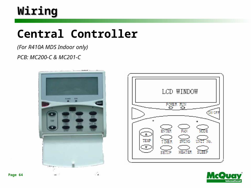
WiringWiring
Central Controller (For R410A MDS Indoor only)
PCB: MC200-C & MC201-C

Page 65
WiringWiring
Central Wired Controller
• Group control for 32 unit.
• Group Control setting: On/Off, Temperature, Operating mode, Fan speed, sleep mode and timer On/Off
• Single unit operation setting: On/Off, Temperature, Operating Mode, Fan speed and sleep mode.
• Timer setting: timer on/off all units.
• Display Circularly: display each unit temperature, mode, fan speed, running and fault code one by one.
• Real time clock: Required battery to maintain the time if no power supply.
Page 66
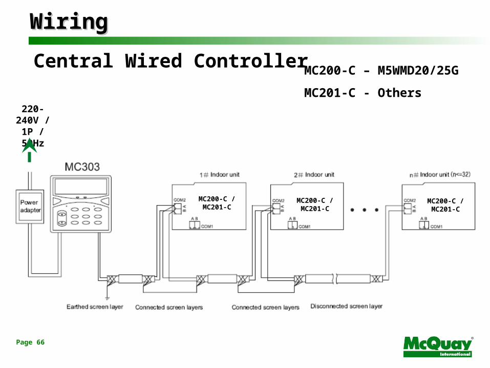
WiringWiring
Central Wired Controller
220-240V /
1P / 50Hz
MC200-C / MC201-C
MC200-C / MC201-C
MC200-C / MC201-C
MC200-C – M5WMD20/25G
MC201-C - Others

Page 67
WiringWiring
Central Wired Controller
Dimension
Installation

Page 68
Gateway
Computer
Indoor unitsOutdoor units
RS485
RS232
1.1. Display ID status & error historyDisplay ID status & error history2.2. Monitor & Control Monitor & Control 3.3. Daily, Weekly & Holiday timer settingDaily, Weekly & Holiday timer setting
1.1. Display ID status & error historyDisplay ID status & error history2.2. Monitor & Control Monitor & Control 3.3. Daily, Weekly & Holiday timer settingDaily, Weekly & Holiday timer setting
Ain Bin Apc Bpc
WiringWiring

Page 69
WiringWiring
Communication Wires
Necessary distance from communication wires to the power supply cable
Parallel distance (d)
≤ 10A 300mm
50A 500mm
100A 1,000mm
≥ 100A 1,500mm
Current of power supply
≥ 100V
Problem may happen due the electromagnetic interference if the communication line is too close with the power cable.

Page 70
Summary

Page 71
SummarySummary
3 basic rules of refrigerant pipe work :
- Dry, Clean and air tight
Both liquid and gas pipe should be insulate separately
The communication wires must be in the same polarity
DO NOT wrap the power cable and communication wire together

Page 72
The End The End


