Embed Size (px)
Citation preview
TAC RADIOS
MULTI-SERVICE TACTICS,
TECHNIQUES, AND PROCEDURES FOR TACTICAL
RADIOS
ATP 6-02.72
MCRP 3-40.3A NTTP 6-02.2
AFTTP 3-2.18
NOVEMBER 2013
DISTRIBUTION STATEMENT A: Approved for public release; distribution is unlimited.
*Supersedes FM 6-02.72/MCRP 3-40.3A/NTTP 6-02.2/AFTTP(I) 3-2.18 dated 14 June 2002; FM 6-02.74/MCRP 3-40.3E/NTTP 6-02.6/AFTTP(I) 3-2.48/COMDTINST M2000.7A dated 20 November 2007; and FM 6-02.771/MCRP 3-40.3F/NTTP 6-02.7/AFTTP(I) 3-2.49 dated 7 May 2004 respectively.
FOREWORD
This multi-Service tactics, techniques, and procedures (MTTP) publication is a project of the Air Land Sea Application (ALSA) Center in accordance with the memorandum of agreement between the Headquarters of the Army, Navy, Air Force, and Marine Corps doctrine commanders directing ALSA to develop MTTP publications to meet the immediate needs of the warfighter. This MTTP publication has been prepared by ALSA under our direction for implementation by our respective commands and for use by other commands as appropriate.
KIRBY R. BROWN Deputy to the Commanding General US Army Combined Arms Center C
William F. Mullen III Brigadier General, US Marine Corps Director Capabilities Development Directorate
TERRY B. KRAFT Rear Admiral, US Navy Commander Navy Warfare Development Command
WALTER D. GIVHAN Major General, US Air Force Commander Curtis E. LeMay Center for Doctrine Development and Education
ROBERT E. DAY Rear Admiral, US Coast Guard Assistant Commandant for Command, Control, Communications, Computers, and Information Technology US Coast Guard Headquarters
This publication is available through the following websites: ALSA (https://wwwmil.alsa.mil/);
US Army (https://armypubs.us.army.mil/doctrine/index.html); US Navy at Navy Doctrine Library System (https://ndls.nwdc.navy.mil);
US Marine Corps (https://www.doctrine.usmc.mil); US Air Force at Air Force E-Publishing System (http://www.e-
publishing.af.mil); and Joint Doctrine, Education, and Training Electronic Information System
(https://jdeis.js.mil/index.jsp?pindex=84).
5 November 2013 ATP 6-02.72/MCRP 3-40.3A i NTTP 6-02.2/AFTTP 3-2.18
PREFACE
1. Purpose
This publication provides a single-source, consolidated reference for tactics, techniques, and procedures in the employment, configuration, and creation of radio nets consisting of voice and data tactical radios.
Note: For the Army, the term “command and control” was replaced with “mission command.” Mission command now encompasses the Army’s philosophy of command (still known as mission command) as well as the exercise of authority and direction to accomplish missions (formerly known as command and control).
2. Scope
This publication describes multi-Service tactics, techniques, and procedures (MTTP) for the tactical employment of tactical radios to support warfighters for training and operations across the spectrum of operations.
3. Applicability
This publication applies to the Army, Navy, Air Force, Marine Corps, and Coast Guard. Also, it may be used by multi-Service and Service components of a joint force to conduct tactical radio training and operations. Procedures herein may be modified to fit specific theater command and control (C2) procedures and allied and foreign national electromagnetic spectrum management requirements.
4. Implementation Plan
Participating Service command offices of primary responsibility will review this publication, validate the information, and where appropriate, reference and incorporate it in Service manuals, regulations, and curricula as follows:
Army. Upon approval and authentication, this publication’s procedures will be incorporated into the United States (US) Army Doctrine and Training Literature Program as directed by the Commander, US Army Training and Doctrine Command (TRADOC). Distribution is in accordance with applicable directives and the initial distribution number listed on the authentication page. Marine Corps.1 The Marine Corps will incorporate the procedures in this publication in US Marine Corps doctrine publications as directed by the Headquarters, Marine Corps (HQMC) Deputy Commandant, Combat Development and Integration (DC, CD&I). Distribution is in accordance with the US Marine Corps Publications Distribution System. Navy. The Navy will incorporate these procedures in US Navy training and doctrine publications as directed by the Commander, Navy Warfare Development Command (NWDC). Distribution is in accordance with Military Standard Requisitioning and Issue Procedure Desk Guide, Naval Supply Systems Command Publication 409.
1 Marine Corps PCN: 144 00007 00
ii ATP 6-02.72/MCRP 3-40.3A 5 November 2013 NTTP 6-02.2/AFTTP 3-2.18
Air Force. The Air Force will incorporate the procedures in this publication in accordance with applicable governing directives. Distribution is in accordance with Air Force Instruction 33-360, Publications Management Program.
Coast Guard. The Coast Guard will incorporate the procedures in this publication in US Coast Guard (USCG) doctrine and training publications as directed by CG-652, Office of Spectrum Management and Telecommunications Policy. Distribution of this publication is in accordance with USCG standard operating procedures.
5. User Information
b. US Army Combined Arms Center; HQMC, DC, CD&I; NWDC; Curtis E. LeMay Center for Doctrine Development and Education; and the Air Land Sea Application (ALSA) Center developed this publication with the joint participation of the approving Service commands. ALSA will review and update this publication as necessary.
c. This publication reflects current joint and Service doctrine, C2 organizations, facilities, personnel, responsibilities, and procedures. Changes in Service protocol, appropriately reflected in joint and Service publications, likewise will be incorporated in revisions to this document.
d. Recommended changes for improving this publication are encouraged. Key your comments to the specific page and paragraph, and provide a rationale for each recommendation. Send comments and recommendations directly to the appropriate Service doctrine centers listed below.
Army
Commander, US Army Combined Arms Center ATTN: ATZL-MCK-D Fort Leavenworth, KS 66027-6900 DSN 552-4885 COMM (913) 684-4885 E-mail: [email protected]
Marine Corps
Deputy Commandant for Combat Development and Integration ATTN: C116 3300 Russell Road, Suite 204 Quantico, VA 22134-5021 DSN 278-3616/6233 COMM (703) 784-3616/6233 E-mail: [email protected]
Navy
Commander, Navy Warfare Development Command ATTN: N52 1530 Piersey St, Building O-27 Norfolk, VA 23511-2723 DSN 341-4185 COMM (757) 341-4185 E-mail: [email protected]
5 November 2013 ATP 6-02.72/MCRP 3-40.3A iii NTTP 6-02.2/AFTTP 3-2.18
Air Force
Commander, Curtis E. LeMay Center for Doctrine Development and Education ATTN: DDJ 401 Chennault Circle Maxwell AFB, AL 36112-6428 DSN 493-7864/1681 COMM (334) 953-7864/1681 E-mail: [email protected]
Coast Guard
Commandant (CG-6421) US Coast Guard Stop 7101 2703 Martin Luther King Jr Ave SE Washington, DC 20593-7101 COMM: (202) 475-3454 E-mail:[email protected]
ALSA
Director, ALSA Center 114 Andrews Street Joint Base Langley-Eustis VA 23665-2785 DSN 575-0902 COMM (757) 225-0902 E-mail: [email protected]
iv ATP 6-02.72/MCRP 3-40.3A 5 November 2013 NTTP 6-02.2/AFTTP 3-2.18
SUMMARY OF CHANGES ATP 6-02.72/MCRP 3-40.3A/NTTP 6-02.2/AFTTP 3-2.18, Multi-Service Tactics, Techniques, and Procedures for Tactical Radios.
This revision, 5 November 2013, provides the following changes: Updates :
• Combines the multi-Service tactics, techniques, and procedures (MTTP) for tactical radios, HAVE QUICK (HQ), and high frequency-automatic link establishment (HF-ALE) into one MTTP called Tactical Radios.
• Revises the table of contents. • Consolidates and standardizes planning and net management to apply to
any radio network. • Updates Service organizational structure for encryption and data
distribution. Deletions: • Removes technical manual data for the HF-ALE, enhanced position location
reporting system (EPLRS), single-channel ground and airborne radio system (SINCGARS), and HQ radios.
• Removes obsolete data. Additions: • Adds sections for very high frequency, ultrahigh frequency, and multiband
radios. • Incorporates existing EPLRS, SINCGARS, and HQ information under the
appropriate radio band sections. • Incorporates Link 16 data. • Adds a brief discussion of satellite communications radio in the overview
section. • Adds a discussion of methods of transporting radios and associated
considerations for power and coverage in the overview section. • Adds an equipment nomenclature matrix that lists what radio works in what
frequency bands, as well as “other” names for the same type of radio to bridge Service differences in radio naming conventions.
• Adds a discussion on spectrum management. • Adds a section discussing communications security management.
DISTRIBUTION STATEMENT A: Approved for public release; distribution is unlimited.
*Supersedes FM 6-02.72, 6-02.74, 6.02-771/MCRP 3-40.3A, 3-40.3E, 3-40.3F/NTTP 6-02.2, 6-02.6, 6-02.7/AFTTP 3-2.18, 3-2.48, 3-2.49, dated June 2002, November 2007, May 2004 respectively. 5 November 2013 ATP 6-02.72/MCRP 3-40.3A v NTTP 6-02.2/AFTTP 3-2.18
ATP 6-02.72 [FM 6-02.72] MCRP 3-40.3A
NTTP 6-02.2 AFTTP 3-2.18
ATP 6-02.72 [FM 6-02.72] US Army Combined Arms Center Fort Leavenworth, Kansas
MCRP 3-40.3A Headquarters, USMC, Deputy Commandant, CD&I, Quantico, Virginia
NTTP 6-02.2 Navy Warfare Development Command Norfolk, Virginia
AFTTP 3-2.18 Curtis E. LeMay Center for Doctrine Development and Education
Maxwell Air Force Base, Alabama
5 November 2013
TAC RADIOS MULTI-SERVICE TACTICS, TECHNIQUES, AND
PROCEDURES FOR TACTICAL RADIOS
EXECUTIVE SUMMARY .............................................................................. IX CHAPTER I TACTICAL RADIO (VOICE AND DATA) ................................. 1
1. Overview ..................................................................................... 1 2. Functions and Responsibilities .................................................... 1 3. Planning and Employment Considerations ................................. 2 4. Network Management ................................................................. 3 5. Spectrum Management ............................................................... 4 6. COMSEC Management .............................................................. 6 7. SATCOM-capable Radios ........................................................... 7
CHAPTER II HIGH FREQUENCY RADIOS ................................................. 9 1. Overview ..................................................................................... 9 2. ALE............................................................................................ 17 3. Automatic Link Establishment Parameters ............................... 21 4. Interoperability ........................................................................... 23
vi ATP 6-02.72/MCRP 3-40.3A 5 November 2013 NTTP 6-02.2/AFTTP 3-2.18
CHAPTER III VERY HIGH FREQUENCY RADIOS ...................................... 27 1. Overview ................................................................................... 27 2. SINCGARS................................................................................ 27
CHAPTER IV ULTRAHIGH FREQUENCY RADIOS .................................... 43 1. Overview ................................................................................... 43 2. EPLRS....................................................................................... 43 3. HQ ............................................................................................. 52 4. Link 16 ....................................................................................... 55
CHAPTER V MULTIBAND HIGH FREQUENCY, VERY HIGH FREQUENCY, AND ULTRAHIGH FREQUENCY RADIOS .................................................. 59
1. Overview ................................................................................... 59 2. Multiband Radio Example ......................................................... 59 3. Airborne and Maritime ............................................................... 61 4. Ground and Vehicular ............................................................... 62 5. Portable (Manpack and Hand-held) .......................................... 62
APPENDIX A STANDARD FREQUENCY ACTION FORMAT .................... 63 APPENDIX B FEDERAL HIGH FREQUENCY GLOBAL COMMUNICATIONS SYSTEM ........................................................................................................ 65
1. Overview ................................................................................... 65 2. HFGCS Parameters .................................................................. 65
APPENDIX C ESTABLISHED AND PROPOSED AUTOMATIC LINK ESTABLISHMENT NETWORKS .................................................................. 69
1. Established Networks ................................................................ 69 2. Shared Resources .................................................................... 69 3. COMSEC................................................................................... 70 4. Proposed Network ..................................................................... 70
APPENDIX D AUTOMATIC LINK ESTABLISHMENT EXCLUSION BAND LISTING ........................................................................................................ 71 APPENDIX E JOINT INTEROPERABILITY TEST COMMAND CERTIFIED AUTOMATIC LINK ESTABLISHMENT MATRIX ......................................... 73
1. Overview ................................................................................... 73 2. Testing and Certification ........................................................... 73
APPENDIX F HIGH FREQUENCY-AUTOMATIC LINK ESTABLISHMENT COMMUNICATION PLAN EXAMPLE .......................................................... 75 APPENDIX G HIGH FREQUENCY-AUTOMATIC LINK ESTABLISHMENT RADIO PROGRAMMING APPLICATION EXAMPLE .................................. 77
1. Third Generation (3G) Utility Functions ..................................... 77 2. The 3G, 3G+: Link Quality Analysis (LQA) ................................ 77 3. The 3G, 3G+: Time of Day (TOD) ............................................. 77 4. The 3G, 3G+: TOD Role ........................................................... 77
5 November 2013 ATP 6-02.72/MCRP 3-40.3A vii NTTP 6-02.2/AFTTP 3-2.18
5. The 3G, 3G+: View List of Linked Radios ................................. 78 6. The 3G Operation ..................................................................... 78 7. Place an Automatic Link Establishment (ALE) Call in 3G+ ....... 79 8. ALE: Program/Operation ........................................................... 79 9. ALE Configuration ..................................................................... 82 10. To Tear/Clear Down a Connected ALE Link ............................. 83 11. To Perform a Net Call (Every Member in the Net is Called) ..... 83 12. Automatic Message Display (AMD) .......................................... 83 13. View LQA Exchange Scores ..................................................... 84 14. Making an ALE Call ................................................................... 84
APPENDIX H HIGH FREQUENCY PROPAGATION PROGRAMS ............. 85 APPENDIX I SINGLE-CHANNEL GROUND AND AIRBORNE RADIO SYSTEM NETWORK MANAGEMENT ......................................................................... 87
1. Frequency Hopping (FH) Net Operations ................................. 87 2. Net Opening .............................................................................. 87 3. Late Net Entry ........................................................................... 88
APPENDIX J HAVE QUICK PLANNING ACTIONS .................................... 89 APPENDIX K HAVE QUICK NET MANAGEMENT REQUIREMENTS ....... 93
1. General...................................................................................... 93 2. Basic HQ I Nets ......................................................................... 93 3. HQ II Nets.................................................................................. 93
APPENDIX L HAVE QUICK TECHNICAL DATA ........................................ 97 1. Word-of-day (WOD) .................................................................. 97 2. Time-of-day (TOD) .................................................................... 98 3. Net Identification Number ........................................................ 101
APPENDIX M EQUIPMENT NOMENCLATURE MATRIX ........................... 103 REFERENCES .............................................................................................. 109 GLOSSARY .................................................................................................. 111
List of Figures Figure 1. Propagation Paths for HF Radio Waves .................................... 11 Figure 2. Incident Angle ............................................................................ 12 Figure 3. Layers of the Ionosphere ........................................................... 14 Figure 4. Eleven-Year Sunspot Cycle ....................................................... 16 Figure 5. Automatic Link Establishment Linking Sequence ...................... 18 Figure 6. Echelons Capable of Generating FH Data ................................. 28 Figure 7. Loadset Data Distribution within Army Units .............................. 30 Figure 8. Loadset Data Distribution within Marine Corps Units ................. 34 Figure 9. Loadset Data Distribution within Navy Forces ........................... 37 Figure 10. Loadset Data Distribution within Air Force Units ...................... 39 Figure 11. Host Tactical System Interfaces to an EPLRS ......................... 46 Figure 12. Army Tactical Internet Brigade and Below Architecture ........... 47 Figure 13. Marine Corps EPLRS Application ............................................ 49
viii ATP 6-02.72/MCRP 3-40.3A 5 November 2013 NTTP 6-02.2/AFTTP 3-2.18
Figure 14. Amphibious Assault Direction .................................................. 50 Figure 15. Situation Awareness Data Link Network .................................. 51 Figure 16. JTIDS Class 2M, AN/GSQ-240 Radio Set ............................... 56 Figure 17. Army MIDS LVT-2, AN/USQ-140 ............................................. 57 Figure 18. AN/PRC-148 Multiband Hand-held Radio ................................ 60 Figure 19. AN/PRC-152 Multiband Hand-held Radio ................................ 61 Figure 20. JTRS AN/PRC-155 Networking Manpack Radio ..................... 61 Figure 21. HF Global Communications System Network Architecture ...... 65
List of Tables
Table 1. Link Quality Analysis Matrix ........................................................ 19 Table 2. HF-ALE Self-Addressing ............................................................. 25 Table 3. Summary of Interoperable HQ Operating Modes Operation and Features .................................................................................................... 54 Table 4. Standard Frequency Action Format Example for SINCGARS .... 63 Table 5. Standard Frequency Action Format Example ............................. 64 Table 6. Recommended ALE Configuration Parameters .......................... 65 Table 7. Recommended Joint ALE System Parameters ........................... 66 Table 8. Recommended Joint ALE Channel Parameters .......................... 67 Table 9. JITC Certified ALE Radios Certification Matrix ............................ 73 Table 10. Example of a Communications Plan (Part 1) ............................ 75 Table 11. Example of a Communications Plan (Part 2) ............................ 75 Table 12. HAVE QUICK Planning Actions ................................................ 89 Table 13. HQ II FM T-Net Frequencies (Megahertz) ................................. 95 Table 14. Tactical Radio Equipment Nomenclature ................................ 103
5 November 2013 ATP 6-02.72/MCRP 3-40.3A ix NTTP 6-02.2/AFTTP 3-2.18
EXECUTIVE SUMMARY
TAC RADIOS
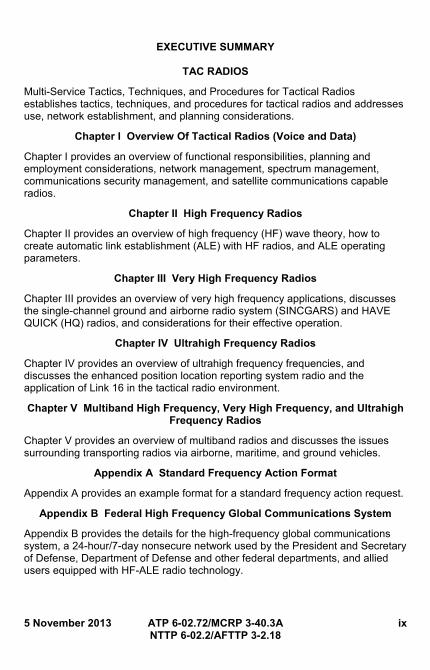
Multi-Service Tactics, Techniques, and Procedures for Tactical Radios establishes tactics, techniques, and procedures for tactical radios and addresses use, network establishment, and planning considerations.
Chapter I Overview Of Tactical Radios (Voice and Data)
Chapter I provides an overview of functional responsibilities, planning and employment considerations, network management, spectrum management, communications security management, and satellite communications capable radios.
Chapter II High Frequency Radios
Chapter II provides an overview of high frequency (HF) wave theory, how to create automatic link establishment (ALE) with HF radios, and ALE operating parameters.
Chapter III Very High Frequency Radios
Chapter III provides an overview of very high frequency applications, discusses the single-channel ground and airborne radio system (SINCGARS) and HAVE QUICK (HQ) radios, and considerations for their effective operation.
Chapter IV Ultrahigh Frequency Radios
Chapter IV provides an overview of ultrahigh frequency frequencies, and discusses the enhanced position location reporting system radio and the application of Link 16 in the tactical radio environment.
Chapter V Multiband High Frequency, Very High Frequency, and Ultrahigh Frequency Radios
Chapter V provides an overview of multiband radios and discusses the issues surrounding transporting radios via airborne, maritime, and ground vehicles.
Appendix A Standard Frequency Action Format
Appendix A provides an example format for a standard frequency action request.
Appendix B Federal High Frequency Global Communications System
Appendix B provides the details for the high-frequency global communications system, a 24-hour/7-day nonsecure network used by the President and Secretary of Defense, Department of Defense and other federal departments, and allied users equipped with HF-ALE radio technology.
x ATP 6-02.72/MCRP 3-40.3A 5 November 2013 NTTP 6-02.2/AFTTP 3-2.18
Appendix C Established and Proposed Automatic Link Establishment Networks
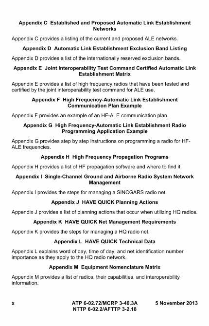
Appendix C provides a listing of the current and proposed ALE networks.
Appendix D Automatic Link Establishment Exclusion Band Listing
Appendix D provides a list of the internationally reserved exclusion bands.
Appendix E Joint Interoperability Test Command Certified Automatic Link Establishment Matrix
Appendix E provides a list of high frequency radios that have been tested and certified by the joint interoperability test command for ALE use.
Appendix F High Frequency-Automatic Link Establishment Communication Plan Example
Appendix F provides an example of an HF-ALE communication plan.
Appendix G High Frequency-Automatic Link Establishment Radio Programming Application Example
Appendix G provides step by step instructions on programming a radio for HF-ALE frequencies.
Appendix H High Frequency Propagation Programs
Appendix H provides a list of HF propagation software and where to find it.
Appendix I Single-Channel Ground and Airborne Radio System Network Management
Appendix I provides the steps for managing a SINCGARS radio net.
Appendix J HAVE QUICK Planning Actions
Appendix J provides a list of planning actions that occur when utilizing HQ radios.
Appendix K HAVE QUICK Net Management Requirements
Appendix K provides the steps for managing a HQ radio net.
Appendix L HAVE QUICK Technical Data
Appendix L explains word of day, time of day, and net identification number importance as they apply to the HQ radio network.
Appendix M Equipment Nomenclature Matrix
Appendix M provides a list of radios, their capabilities, and interoperability information.
5 November 2013 ATP 6-02.72/MCRP 3-40.3A xi NTTP 6-02.2/AFTTP 3-2.18
PROGRAM PARTICIPANTS
The following commands and agencies participated in the development of this publication:
Joint
Deputy Director J7-Joint and Coalition Warfighting/Joint Doctrine Support Division, Suffolk, VA
Army
United States (US) Army Combined Arms Center, Fort Leavenworth, KS
Marine Corps
US Marine Corps Combat Development Command, Quantico, VA
Navy
Navy Warfare Development Command, Norfolk, VA
Air Force
Curtis E. LeMay Center for Doctrine Development and Education, Maxwell Air Force Base, AL
Coast Guard
US Coast Guard (CG-6421), Washington, DC.

This page intentionally left blank.
5 November 2013 ATP 6-02.72/MCRP 3-40.3A 1 NTTP 6-02.2/AFTTP 3-2.18
Chapter I TACTICAL RADIO (VOICE AND DATA)
1. Overview
Tactical radios are deployed at all echelons and provide users the capability to conduct interoperable voice and data communications. These systems use high frequency (HF), ultrahigh frequency (UHF), very high frequency (VHF) bands, satellite communications (SATCOM), and multiband radios. The equipment may be specifically designed for military use and may include commercial off-the-shelf (COTS) radios. Each system has unique capabilities and characteristics commanders use to determine how to employ each system, depending on the mission and other factors. This publication discusses voice and data tactical radio systems in common use among the Services. It also reviews the basic operational and planning procedures for these systems in a joint environment.
2. Functions and Responsibilities
Air, land, and sea forces all require effective systems for command, control, and communications. For a wide variety of combat forces, single-channel (SC) VHF-frequency modulation (FM) combat net radio systems provide this capability. The VHF-FM channels are especially important for support of ground operations and forces.
a. The Joint Chiefs of Staff (JCS) provides overall guidance on joint United States (US) military frequency engineering and management. The JCS have delegated certain authority to carry out this responsibility to the chairman of the Military Communications-Electronics Board (MCEB). The Chairman of the JCS reserves the authority to resolve disputes.
b. The joint force commander (JFC) is responsible for all facets of communications in the area of operations. The JFC delegates the authority for communications coordination to the communications or signal special staff office communications system directorate of a joint staff; command, control, communications, and computer systems staff directorate (J-6). Multi-Service coordination maintains interoperability, establishes total force requirements, and reconciles the unique needs of each Service.
c. The JFC’s J-6 is a functionally organized staff that controls, coordinates and publishes plans and procedures dealing with all aspects of joint service operations or communication exercises. In addition to ensuring interoperability and compatibility, J-6 is responsible for: (1) Designating and distributing joint net parameters.
(2) Publishing standing operating procedures (SOPs) for communications.
(3) Providing spectrum management.
(4) Hosting government communication coordination.
(5) Controlling communications security (COMSEC) assignment, use, and management.
2 ATP 6-02.72/MCRP 3-40.3A 5 November 2013 NTTP 6-02.2/AFTTP 3-2.18
(6) Providing time synchronization.
(7) Establishing and assigning hierarchy for joint nets.
d. In joint operations, all Services shall work within their component to ensure the use of compatible radios. Spectrum management must occur at the highest multi-Service command level. This coordination is accomplished with the creation of a communications coordination committee. The communications coordination committee should include:
(1) The COMSEC custodian from the appropriate staff section.
(2) The special plans officer from the operations directorate of a joint staff (J-3) plans section.
(3) The host-country frequency coordinator.
(4) Spectrum managers from the joint and Service spectrum management office.
(5) The aviation officer from the J-3 office.
3. Planning and Employment Considerations
This section contains communications planning considerations and is intended to be a general checklist for joint communications planning. This list is not all inclusive.
a. Receive the mission.
b. Determine the geographic operational area.
c. Analyze the commander’s intent, commander’s critical information requirements, and planning guidance.
d. Determine the commander’s communication and information exchange requirements.
e. Determine potential offensive electronic warfare (EW) capabilities and identify an electronic protection (EP) plan.
f. Determine defensive EW capabilities and identify a communications compatibility plan.
g. Determine hierarchy for required nets and establish command relationships.
h. Determine interoperability among forces.
i. Receive frequency management planning guidance.
j. Receive key management plans for COMSEC assignment and use.
k. Receive SOPs for communications.
l. Receive joint operating parameters.
m. Develop local emergency destruction plans.
n. Distribute SOPs to all participants.
o. Generate a local plan to check the network.
p. Develop a pack-out plan.
5 November 2013 ATP 6-02.72/MCRP 3-40.3A 3 NTTP 6-02.2/AFTTP 3-2.18
q. Identify any special communications requirements.
r. Receive frequency authorization for nets.
s. Receive general information security/information assurance (IA) requirements.
t. Identify coalition communication requirements.
u. Determine communication requirements for geographically separated organic units.
Note: Appendix M, table 14 lists radio nomenclature and includes compatibility and capability listings for several types of radios commonly used by all the Services.
4. Network Management
Net management is a process of discipline and procedures established by the net control authority. Many nets utilize a net control station (NCS) which manages or directs traffic on the net. Net management requirements will vary based on the communication means and/or systems utilized. Successful net management requires detailed coordination between communications support personnel throughout the network and the users requiring their support. While there are some common aspects among all of the net types discussed in this publication (such as time synchronization), there are also some unique traits within each type of net. These are discussed in the following paragraphs.
a. HF-automatic link establishment (ALE). ALE allows a more effective use of the HF spectrum. By providing real-time updates of the best frequency from a selected scan list, the reliability and quality of HF communications is increased. From an operator standpoint, maintaining and managing an ALE network is similar to using a cell phone. However, from a technical standpoint, maintaining and managing an ALE network is complex. Centralized management of an ALE network is essential to ensuring integrity and efficiency of communications.
b. Enhanced position location reporting system (EPLRS). The system planner in the EPLRS network operations security center (NOSC) must anticipate EPLRS network needs to keep pace with the changing dynamics in the operational environment. There are two main components of EPLRS: (1) NCS. The NCS contains tactical computers that enable automated
technical control and centralized dynamic network management of EPLRS. The NCS is the primary technical control interface. NCS software provides dynamic network monitoring and resource assignment that satisfies requirements for communications, navigation, identification (ID) data distribution, and position location.
(2) Radio set (RS). The RS provides secure, jam-resistant, digital communications and accurate position location capabilities. The RS accepts and implements NCS-issued commands and reports its status to the NCS. These reports are essential for accomplishing the
4 ATP 6-02.72/MCRP 3-40.3A 5 November 2013 NTTP 6-02.2/AFTTP 3-2.18
automatic control of EPLRS. The RS consists of a remote terminal (RT), user readout (URO) device, and an appropriate installation kit for ground, vehicle, or airborne use.
c. Frequency hopping (FH) radios. FH is the repeated switching of frequencies during radio transmission and minimizing unauthorized interception or jamming of radio transmissions. The overall bandwidth required for FH is much wider than that required to transmit the same information using only one carrier frequency. Protection against eavesdropping and jamming is improved by employing encryption through FH radios.
d. Single-channel ground and airborne radio system (SINCGARS) and HAVE QUICK (HQ) are timing-based, FH networks require all net users to be synchronized.
(1) SINCGARS. FH-master (FH-M) mode. Only one radio in each FH radio net will use this mode. The FH-M radio maintains the radio net’s synchronization time and performs the electronic remote fill (ERF). Normally the designated or alternate NCS will operate in the FH-M mode. See appendix I for additional net management information.
(2) HQ. See appendix K for additional net management information.
5. Spectrum Management
a. Spectrum management responsibilities. A spectrum is a finite natural resource shared by all radio wave transmitters. All tactical radios fall within the 3 kilohertz to 30 gigahertz (GHz) radio spectrum; shared with: television broadcasting, amplitude modulation (AM) and FM radio, civil service, cell phone, civilian radio communication systems, and the global positioning system (GPS).
(1) Legal and regulatory principles:
(a) All nations have a sovereign right to their spectrum and use of their spectrum requires host nation approval at the international and national levels. The primary use of a spectrum, for many nations, is economic, not military. All nations have a sovereign right to allocate the spectrum as needed to support their national interests, but the successful conduct of military operations requires the JFC to work with the nation at issue to balance these rights with the need to maintain security of US and multinational forces.US national spectrum authority. Title 47, US Code, section 151 et seq., The Communications Act of 1934 established separate control of federal government and non-federal government use of the radio frequency (RF) spectrum. Under this act, the only government agencies that assign and control the use of frequencies within the US are the National Telecommunications and Information Administration (NTIA) and Federal Communications Commission (FCC). NTIA assigns and regulates frequencies for federal users. The NTIA governs all federal (including military) use of the RF
5 November 2013 ATP 6-02.72/MCRP 3-40.3A 5 NTTP 6-02.2/AFTTP 3-2.18
spectrum within the US and its possessions. The FCC assigns and regulates frequencies for non-federal users. Non-federal users include private citizens, companies, and state and local government agencies. The RF spectrum is allocated between government (federal) and non-government (civil) users with portions of the spectrum shared between the two. Federal users must utilize frequency bands allocated for government or shared use. A government frequency assignment may be authorized in a non-government band provided the request is coordinated and granted approval by the FCC.
(b) International spectrum authority. The International Telecommunication Union (ITU) is the international body responsible for international frequency allocations, worldwide telecommunications standards, and telecommunications development activities. The US is one of the 193 member nations comprising the ITU. International agreements signed by the President and ratified by the Senate gain treaty status. RF spectrum is a natural resource independently managed by each sovereign nation within its boundaries.
(2) Spectrum management abroad. The principles of international spectrum authority must be kept in mind when US military forces operate abroad. Joint force operations require spectrum management at theater levels for interoperability. Combined operations will also require spectrum management if allies use compatible radios. Inside the borders, airspace, or territorial waters of foreign countries, US forces are subject to existing international agreements and have no independent authority to use RFs. The US Department of State and the theater commander coordinate these agreements with allied governments.
(a) Before obtaining RF spectrum authorization abroad, it is imperative the commander keep in mind the principle of effective and efficient use of the spectrum, in addition to other principles of international spectrum authority. For example, congestion of radio spectrum in the Republic of Korea (ROK) is so significant it has become increasingly difficult to assign new sole-user frequencies. The ROK Ministry of Information and Communications, as the assignment authority for all RF requirements in the ROK, closely manages the RF spectrum in the ROK and requires strong justification for permanent frequency assignments.
(b) Commanders must critically review requirements and requests for new frequency assignments. Every effort should be made to share existing resources and ensure the continued use of currently assigned frequencies is absolutely necessary to accomplish the mission.
6 ATP 6-02.72/MCRP 3-40.3A 5 November 2013 NTTP 6-02.2/AFTTP 3-2.18
(3) Frequency assignments. Frequency assignments are area dependent; thus, when units change their area of responsibility (AOR), frequency planning must be addressed early to minimize operational disruptions.
(a) Users must approach the spectrum management process in a manner consistent with the combatant commander’s policy for spectrum management. The J-6 usually develops the commander’s policy, which includes documents such as the operations plan and joint communications-electronics operating instructions (JCEOI). At each level, users must identify and submit spectrum requirements to the joint frequency management office (JFMO) or joint spectrum management element (JSME), as appropriate. Users are also responsible for operating their electromagnetic radiating equipment in accordance with parameters authorized by the frequency assignment process. Due to the long lead time required to coordinate spectrum assignments, users should submit their requests for frequencies early in their planning cycle. After receiving assignments, the JFMO/JSME will generate editions to the JCEOI/signal operating instructions, print out a hard copy for issuance and usage, and create frequency lists needed for operations.
(b) Frequency assignments may be classified either by the MCEB or by the combatant commander. A Security Classification Guide (SCG) may apply to frequency assignments. An SCG specific to an operations plan also may address frequency assignments
(4) Reporting. Multi-Service components must submit a standard frequency action format (see appendix A, tables 4 and 5) for the RF needs of the organization, and any other special communication requirements to the J-6 spectrum manager. The frequency manager will validate the master net list and net group assignments prior to generation.
6. COMSEC Management
a. COMSEC management is a Department of Defense (DOD) program implemented to ensure voice and data communications are safeguarded to guarantee operational security through using cryptographic (CRYPTO) keying material, controlled cryptographic items (CCI), and handling and destroying classified materials.
b. Electronic key management system managers and custodians handle the documentation issued to users regarding destroying CRYPTO and classified materials; and maintaining, safeguarding, and using CCIs.
c. Access to classified COMSEC material must be restricted to properly cleared individuals whose official duties require such access. Although an individual has a security clearance and/or holds a certain rank or position, this does not entitle that individual access to COMSEC material. Access to classified, or unclassified COMSEC material requires a valid need-to-know.
5 November 2013 ATP 6-02.72/MCRP 3-40.3A 7 NTTP 6-02.2/AFTTP 3-2.18
All personnel having access to COMSEC keying material must be authorized in writing by the commanding officer.
d. CRYPTO fill devices/CCI should be stored only in General Services Administration-approved containers or vaults, or positively controlled areas maintained by authorized personnel. Compromised or lost CRYPTO materials MUST be reported to the appropriate chain of command IMMEDIATELY. Failure to do so can result in punishment in accordance with the Uniform Code of Military Justice.
e. Contact the COMSEC manager to ensure the proper key is used on the proper radio net.
7. SATCOM-capable Radios
SATCOM radios provide another means of communications for air, land, and sea forces. SATCOM radios provide standalone, terrain independent, line-of-sight (LOS)/beyond line-of-sight (BLOS), secure voice, and data communications. They can be employed to provide warfighters long-distance, wide-area, fixed, or on-the-move, ground, maritime, and ground-to-air communications. Employment of SATCOM radios enhances combatant commands and other users’ ability to network over large, geographically dispersed areas.
a. AN/PSC-5 Spitfire/Shadowfire. These are small, lightweight terminals capable of operating in VHF and UHF LOS modes. They provide half-duplex, secure data, and digital voice communications via demand assigned multiple access (DAMA). The AN/PSC-5 Spitfire/Shadowfire has a frequency range of 30.000 to 420.000 megahertz (MHz).
b. AN/PSC-5D multiband multi-mission radio. This radio is capable of operating in VHF and UHF LOS modes. SINCGARS and HQ II capable, the AN/PSC-5D offers a higher frequency range than the Spitfire or Shadowfire. The AN/PSC-5D has a frequency range of 30.000 to 512.000 MHz. It includes an embedded ViaSat data controller which has the capability of passing data communications across a single channel radio.
AN/PRC-117F and AN/PRC-117G multiband radio. The AN/PRC-117F and the AN/PRC-117G provide SATCOM link up for data/voice transfer. The radios can pass critical tactical and routine administrative and logistics information in data and voice modes. The radios are capable of providing LOS, SATCOM, electronic counter-countermeasures, and FH operations (SINCGARS and HQ), and are compatible with all tactical VHF/UHF radios. The AN/PRC-117F has a frequency range of 30.000 to 512.00 MHz. The AN/PRC-117G has a frequency range of 30.000 MHz to 2.000 GHz.

8 ATP 6-02.72/MCRP 3-40.3A 5 November 2013 NTTP 6-02.2/AFTTP 3-2.18
This page intentionally left blank. .

5 November 2013 ATP 6-02.72/MCRP 3-40.3A 9 NTTP 6-02.2/AFTTP 3-2.18
Chapter II HIGH FREQUENCY RADIOS
1. Overview
HF describes the 3 to 30 MHz portion of the radio spectrum. Many military HF capable radios can operate at frequencies as low as 1.6 MHz. This frequency range can provide short- and long-haul communications. However, it is greatly influenced by the Earth’s atmosphere. To communicate effectively in the HF spectrum, it is necessary to understand radio propagation and how the Earth’s atmosphere affects this frequency range.
a. Propagation. Propagation describes how radio signals radiate outward from a transmitting source. A radio transmitter’s antenna emits radio waves much like the wave motion formed by dropping a stone in a pool of water. This action is simple to imagine for radio waves travelling in a straight line in free space. The true path radio waves take, and how the Earth’s atmosphere affects these waves, is more complex.
b. Earth’s atmosphere. The Earth’s atmosphere is divided into three regions called layers. The layers are the troposphere, stratosphere, and ionosphere. Most of the Earth’s weather takes place in the troposphere, which extends from the Earth’s surface to about 10 miles up. The weather variations in temperature, density, and pressure have a great effect on the propagation of radio waves. The stratosphere, which extends from roughly 10 to 30 miles up, has little effect on radio wave propagation. The ionosphere, which extends from 30 to approximately 375 miles up, contains up to four cloud-like layers of electrically charged ions. It is this region and its ionized layers that enable radio waves to propagate great distances. The ionosphere, and how it affects radio wave propagation, is discussed in paragraph 1.c and its sub-paragraphs in this chapter.
c. Types of propagation. There are two basic modes of propagation: ground waves and sky waves. Ground waves travel along the surface of the Earth and are used primarily for short-range communications. Sky waves, reflected by the ionosphere, are “bounced” back to Earth and provide a long-haul communications path. Also, they provide short-range (0 to 180 miles or 300 kilometers (kms)) communication in mountainous terrain.
(1) Ground waves. Ground waves consist of three components: surface, direct, and ground-reflected waves.
(a) Surface waves. Surface waves travel along the surface of the Earth, reaching beyond the horizon. Eventually, surface wave energy is absorbed by the Earth. The effective range of surface waves is largely determined by the frequency and conductivity of the surface over which the waves travel. Bodies of water and flat land have the least amount of absorption, while desert and jungle areas have the greatest. For a given complement of equipment, the range may extend from 200 to 250 miles over a conductive, all-
10 ATP 6-02.72/MCRP 3-40.3A 5 November 2013 NTTP 6-02.2/AFTTP 3-2.18
sea-water path. Over arid, rocky, nonconductive terrain, however, the range may drop to less than 20 miles, even with the same equipment. If terrain is mountainous, the RF signal will be reflected rather than continuing along the Earth’s surface, thus, significantly reducing range. Absorption also increases with an increase in frequency. When trying to communicate using surface wave energy, use the lowest possible frequency.
(b) Direct waves. Direct waves, also known as LOS waves, travel in a straight line and become weaker as distance increases. They may be bent, or refracted, by the atmosphere; extending their useful range slightly beyond the horizon. Transmitting and receiving antennas must be able to “see” each other for LOS communications to take place; therefore, antenna height is critical in determining range. Any obstructions between the two antennas (such as mountains or buildings) can block or reduce the signal using LOS communications. At higher frequencies, reception is optimized by matching the polarization/antenna position of the radios.
(c) Ground-reflected waves. Ground-reflected waves are the portion of the propagated wave reflected from the surface of the Earth between the transmitter and receiver.
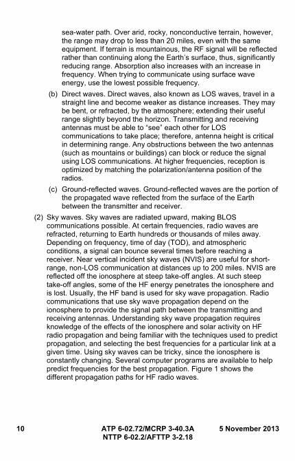
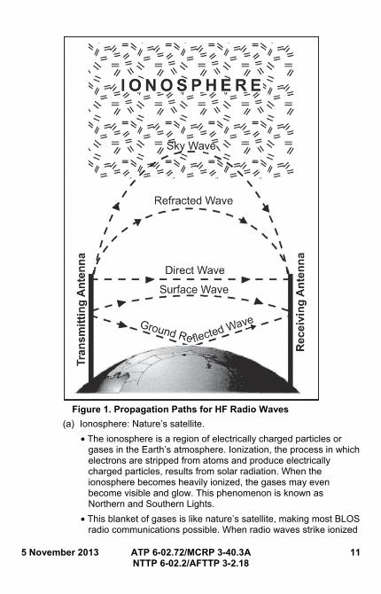
(2) Sky waves. Sky waves are radiated upward, making BLOS communications possible. At certain frequencies, radio waves are refracted, returning to Earth hundreds or thousands of miles away. Depending on frequency, time of day (TOD), and atmospheric conditions, a signal can bounce several times before reaching a receiver. Near vertical incident sky waves (NVIS) are useful for short-range, non-LOS communication at distances up to 200 miles. NVIS are reflected off the ionosphere at steep take-off angles. At such steep take-off angles, some of the HF energy penetrates the ionosphere and is lost. Usually, the HF band is used for sky wave propagation. Radio communications that use sky wave propagation depend on the ionosphere to provide the signal path between the transmitting and receiving antennas. Understanding sky wave propagation requires knowledge of the effects of the ionosphere and solar activity on HF radio propagation and being familiar with the techniques used to predict propagation, and selecting the best frequencies for a particular link at a given time. Using sky waves can be tricky, since the ionosphere is constantly changing. Several computer programs are available to help predict frequencies for the best propagation. Figure 1 shows the different propagation paths for HF radio waves.
5 November 2013 ATP 6-02.72/MCRP 3-40.3A 11 NTTP 6-02.2/AFTTP 3-2.18
Figure 1. Propagation Paths for HF Radio Waves
(a) Ionosphere: Nature’s satellite.
• The ionosphere is a region of electrically charged particles or gases in the Earth’s atmosphere. Ionization, the process in which electrons are stripped from atoms and produce electrically charged particles, results from solar radiation. When the ionosphere becomes heavily ionized, the gases may even become visible and glow. This phenomenon is known as Northern and Southern Lights.
• This blanket of gases is like nature’s satellite, making most BLOS radio communications possible. When radio waves strike ionized
12 ATP 6-02.72/MCRP 3-40.3A 5 November 2013 NTTP 6-02.2/AFTTP 3-2.18
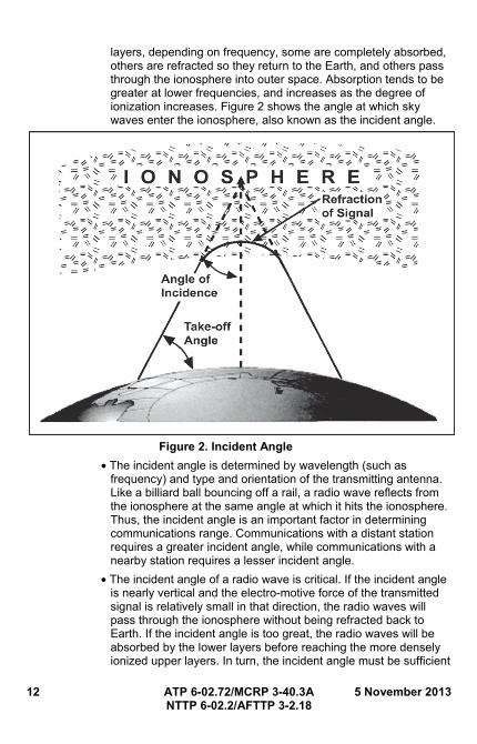
layers, depending on frequency, some are completely absorbed, others are refracted so they return to the Earth, and others pass through the ionosphere into outer space. Absorption tends to be greater at lower frequencies, and increases as the degree of ionization increases. Figure 2 shows the angle at which sky waves enter the ionosphere, also known as the incident angle.
Figure 2. Incident Angle
• The incident angle is determined by wavelength (such as frequency) and type and orientation of the transmitting antenna. Like a billiard ball bouncing off a rail, a radio wave reflects from the ionosphere at the same angle at which it hits the ionosphere. Thus, the incident angle is an important factor in determining communications range. Communications with a distant station requires a greater incident angle, while communications with a nearby station requires a lesser incident angle.
• The incident angle of a radio wave is critical. If the incident angle is nearly vertical and the electro-motive force of the transmitted signal is relatively small in that direction, the radio waves will pass through the ionosphere without being refracted back to Earth. If the incident angle is too great, the radio waves will be absorbed by the lower layers before reaching the more densely ionized upper layers. In turn, the incident angle must be sufficient
5 November 2013 ATP 6-02.72/MCRP 3-40.3A 13 NTTP 6-02.2/AFTTP 3-2.18
to bring the radio wave back to Earth, yet not so great that it will lead to absorption.
(b) Layers of the ionosphere.
• Within the ionosphere, there are four layers of varying ionization, as illustrated in figure 3. Since ionization is caused by solar radiation, the higher layers of the ionosphere tend to be more electrically dense, while the lower layers (protected by the outer layers) experience less ionization. The first layer was discovered in the early 1920s by Sir Edward Victor Appleton, and was designated E for electric waves. Later, D and F were discovered and noted by these letters. The letters A, B, and C will be used to designate future discoveries.
• The D layer is the lowest region affecting HF radio waves. Ionized only during the day, the D layer reaches maximum ionization when the sun is at its zenith, but dissipates quickly toward sunset.
• The E layer reaches maximum ionization at noon. It begins dissipating toward sunset and reaches minimum activity at midnight. Irregular cloud-like formations of ionized gases occasionally occur in the E layer. These regions, known as sporadic E, can support propagation of sky waves at the upper end of the HF band and beyond. Sporadic E regions appear and disappear quickly and at irregular intervals. Therefore, they are difficult to predict. For this reason, E layer communications cannot be depended upon to support mission-essential communications.
• The F layer is the most heavily ionized region of the ionosphere and, therefore, the most important for long-haul communications. At this altitude, the air is thin enough so the ions and electrons recombine very slowly. As a result, this layer retains its ionized properties even after sunset.
• In the daytime, the F layer consists of two distinct layers; F1 and F2. The F1 layer, which exists only in the daytime and is negligible in winter, is not important to HF communications.
• The F2 layer reaches maximum ionization at noon and remains charged at night, gradually decreasing to a minimum just before sunrise.
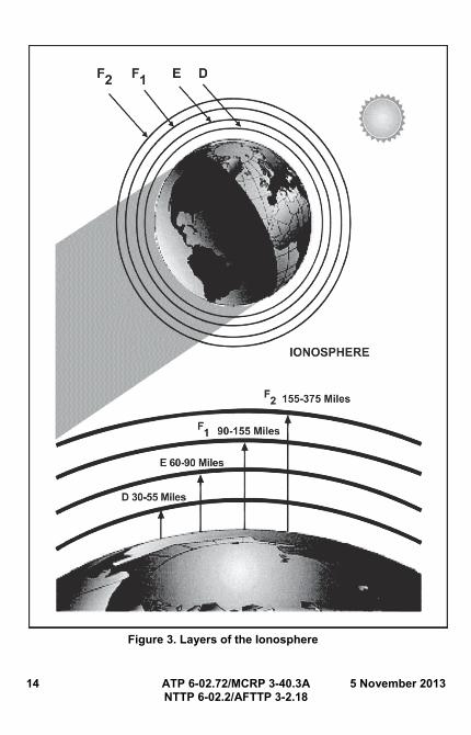
14 ATP 6-02.72/MCRP 3-40.3A 5 November 2013 NTTP 6-02.2/AFTTP 3-2.18
Figure 3. Layers of the Ionosphere
5 November 2013 ATP 6-02.72/MCRP 3-40.3A 15 NTTP 6-02.2/AFTTP 3-2.18
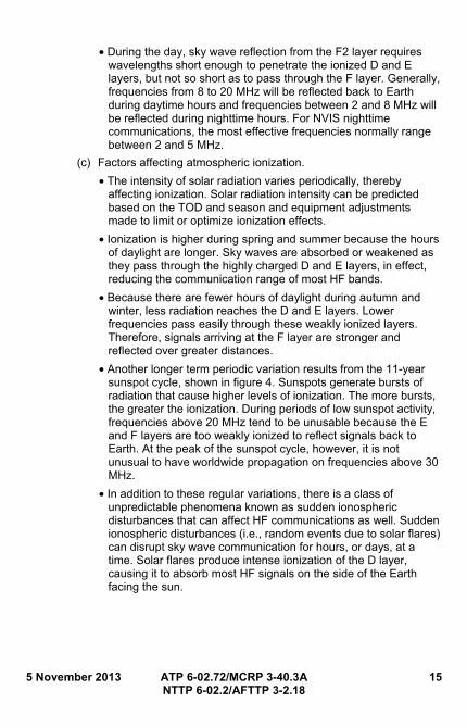
• During the day, sky wave reflection from the F2 layer requires wavelengths short enough to penetrate the ionized D and E layers, but not so short as to pass through the F layer. Generally, frequencies from 8 to 20 MHz will be reflected back to Earth during daytime hours and frequencies between 2 and 8 MHz will be reflected during nighttime hours. For NVIS nighttime communications, the most effective frequencies normally range between 2 and 5 MHz.
(c) Factors affecting atmospheric ionization.
• The intensity of solar radiation varies periodically, thereby affecting ionization. Solar radiation intensity can be predicted based on the TOD and season and equipment adjustments made to limit or optimize ionization effects.
• Ionization is higher during spring and summer because the hours of daylight are longer. Sky waves are absorbed or weakened as they pass through the highly charged D and E layers, in effect, reducing the communication range of most HF bands.
• Because there are fewer hours of daylight during autumn and winter, less radiation reaches the D and E layers. Lower frequencies pass easily through these weakly ionized layers. Therefore, signals arriving at the F layer are stronger and reflected over greater distances.
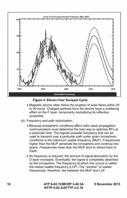
• Another longer term periodic variation results from the 11-year sunspot cycle, shown in figure 4. Sunspots generate bursts of radiation that cause higher levels of ionization. The more bursts, the greater the ionization. During periods of low sunspot activity, frequencies above 20 MHz tend to be unusable because the E and F layers are too weakly ionized to reflect signals back to Earth. At the peak of the sunspot cycle, however, it is not unusual to have worldwide propagation on frequencies above 30 MHz.
• In addition to these regular variations, there is a class of unpredictable phenomena known as sudden ionospheric disturbances that can affect HF communications as well. Sudden ionospheric disturbances (i.e., random events due to solar flares) can disrupt sky wave communication for hours, or days, at a time. Solar flares produce intense ionization of the D layer, causing it to absorb most HF signals on the side of the Earth facing the sun.
16 ATP 6-02.72/MCRP 3-40.3A 5 November 2013 NTTP 6-02.2/AFTTP 3-2.18
Figure 4. Eleven-Year Sunspot Cycle
• Magnetic storms often follow the eruption of solar flares within 20 to 40 hours. Charged particles from the storms have a scattering effect on the F layer, temporarily neutralizing its reflective properties.
(d) Frequency and path optimization.
• Because ionospheric conditions affect radio wave propagation, communicators must determine the best way to optimize RFs at a particular time. The highest possible frequency that can be used to transmit over a particular path under given ionospheric conditions is the maximum usable frequency (MUF). Frequencies higher than the MUF penetrate the ionosphere and continue into space. Frequencies lower than the MUF tend to refract back to Earth.
• As frequency is reduced, the amount of signal absorption by the D layer increases. Eventually, the signal is completely absorbed by the ionosphere. The frequency at which this occurs is called the lowest usable frequency (LUF). The “window” of usable frequencies, therefore, lies between the MUF and LUF.
5 November 2013 ATP 6-02.72/MCRP 3-40.3A 17 NTTP 6-02.2/AFTTP 3-2.18
• The frequency of optimum transmission (FOT) is nominally 85 percent of the MUF. Generally, the FOT is lower at night and higher during the day.
• In addition to frequency, the route the radio signal travels also must be considered in optimizing communications. A received signal may be comprised of components arriving via several routes, including one or more sky wave paths and a ground wave path. The arrival times of these components differ because of differences in path length. The range of time differences is the multipath spread. The effects of multipath spread can be minimized by selecting a frequency as close as possible to the MUF. Higher frequencies are generally less susceptible to atmospheric noise so communications also can be improved by choosing frequencies as close as possible to the MUF.
(e) Propagation prediction techniques.
• Since many of the variables affecting propagation follow repetitive cycles and can be predicted, techniques for effectively determining FOT have been developed.
• A number of propagation prediction computer programs are available (see appendix H). One widely used and effective program is the Voice of America Coverage Analysis Program, which predicts system performance at specific times of day as a function of frequency for a given HF path and a specified complement of equipment.
• Since computerized prediction methods are based on physical calculations and historic data, they cannot account for present conditions affecting communications, such as ionospheric changes caused by random phenomena (interference and noise).
d. Oceanic use and crowding. HF may be used by aircraft in trans-oceanic flight or ships afloat because of the long range, however, the HF spectrum may be very crowded in some oceanic locations.
2. ALE
ALE is a communication system permitting HF radio stations to call and link on the best HF channel automatically. Typically, ALE systems make use of recently measured radio channel characteristics stored in a memory matrix to select the best frequency. The system works like a telephone in that each radio in a network is assigned an address (similar to a call sign). When not in use, each radio receiver constantly scans through its assigned frequencies, listening for calls addressed to it. Appendix C lists established and proposed ALE networks, while appendix D lists the frequency bands excluded from operational use due to international and safety allocations. Appendix B provides details for the High Frequency Global Communications System which is a 24-hour/7-day-a-week
18 ATP 6-02.72/MCRP 3-40.3A 5 November 2013 NTTP 6-02.2/AFTTP 3-2.18
network used by the President and Secretary of Defense, the DOD, and other federal departments, and allied users equipped with HF-ALE radio technology in support of C2 among aircraft, ships and associated ground stations.
a. ALE linking sequence.
(1) The following paragraphs discuss the three parts of the ALE linking sequence.
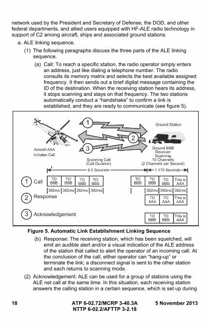
(a) Call: To reach a specific station, the radio operator simply enters an address, just like dialing a telephone number. The radio consults its memory matrix and selects the best available assigned frequency. It then sends out a brief digital message containing the ID of the destination. When the receiving station hears its address, it stops scanning and stays on that frequency. The two stations automatically conduct a “handshake” to confirm a link is established, and they are ready to communicate (see figure 5).
Figure 5. Automatic Link Establishment Linking Sequence
(b) Response: The receiving station, which has been squelched, will emit an audible alert and/or a visual indication of the ALE address of the station that called to alert the operator of an incoming call. At the conclusion of the call, either operator can “hang-up” or terminate the link; a disconnect signal is sent to the other station and each returns to scanning mode.
(2) Acknowledgement: ALE can be used for a group of stations using the ALE net call at the same time. In this situation, each receiving station answers the calling station in a certain sequence, which is set up during
5 November 2013 ATP 6-02.72/MCRP 3-40.3A 19 NTTP 6-02.2/AFTTP 3-2.18
the ALE programming. Net calls must be used judiciously because all called stations need to be in the same propagating region as the calling station.
(3) An HF communications network usually has several channels assigned. The ALE system has a link quality analysis (LQA) process that allows the radio to evaluate each channel to determine the best channel to place a call.
(4) At prescribed intervals, a station can be programmed to measure the signal quality on each assigned frequency by listening to the sounding signals from the other stations in the network. The quality scores are stored in a matrix, listed by the other stations as ID versus channel. When a call to a certain station is initiated, the radio checks the matrix to determine the best quality frequency for the call to that station. It then attempts to link on that frequency. If the link cannot be established on the frequency, it will try again on the next best frequency, and so on until a link is established. If a link is not established after trying all the assigned frequencies, the radio will prompt the operator that a link could not be established. Sometimes when using the HF spectrum, communications between any two points may not be possible. In these cases, it is important to be persistent in attempts to communicate and consider using another station as a relay to get a message across.
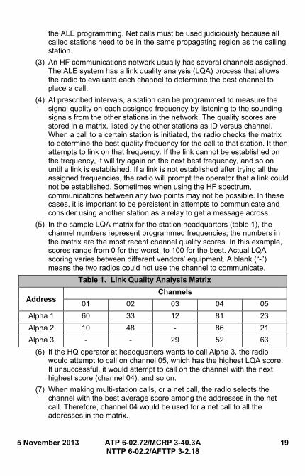
(5) In the sample LQA matrix for the station headquarters (table 1), the channel numbers represent programmed frequencies; the numbers in the matrix are the most recent channel quality scores. In this example, scores range from 0 for the worst, to 100 for the best. Actual LQA scoring varies between different vendors’ equipment. A blank (“-”) means the two radios could not use the channel to communicate.
Table 1. Link Quality Analysis Matrix
Address Channels
01 02 03 04 05
Alpha 1 60 33 12 81 23
Alpha 2 10 48 - 86 21
Alpha 3 - - 29 52 63
(6) If the HQ operator at headquarters wants to call Alpha 3, the radio would attempt to call on channel 05, which has the highest LQA score. If unsuccessful, it would attempt to call on the channel with the next highest score (channel 04), and so on.
(7) When making multi-station calls, or a net call, the radio selects the channel with the best average score among the addresses in the net call. Therefore, channel 04 would be used for a net call to all the addresses in the matrix.
20 ATP 6-02.72/MCRP 3-40.3A 5 November 2013 NTTP 6-02.2/AFTTP 3-2.18
b. Generations of ALE.
(1) Currently two generations of ALE are being used; these are commonly referred to as second generation (2G) and third generation (3G). This document primarily covers the 2G version of ALE. Military Standard (MIL-STDs)-188-141A and B cover 2G ALE.
(2) The newest ALE 3G technology is slowly gaining wide acceptance and use. This technology provides the following advantages over the 2G version of ALE:
(a) Faster link setup time.
(b) Linking at lower signal-to-noise ratios.
(c) Improved network channel efficiency.
(d) Higher performance serial waveforms.
(e) Higher throughput for short and long data messages.
Note: These advantages incorporate synchronous scanning, a burst phase shift keying waveform, and a carrier sense multiple access with a collision avoidance channel access procedure. MIL-STD-188-141B, and North Atlantic Treaty Organization (NATO) standardization agreement 4538 identify the applicable standards that cover the 3G of ALE.
c. Frequency selection.
(1) Frequency selection is important for ALE to function properly. When selecting frequencies to use in a network, consider the times of operation, distance to be communicated, power level, and type of antenna being used.
(2) When using the frequency parameters in the previous paragraph, also use a good propagation program to determine which spectrums will propagate. Appendix H lists some of the available propagation software programs and contact information.
(3) Consulting the frequency manager early in the process may save a lot of work, since the manager may already have lists of approved frequencies that can be used for particular functions in given areas.
d. Limitations.
(1) ALE is a tool that automates HF linking and frequency selection. It does not replace a properly trained HF operator. Knowledge of the specific radio equipment being used, propagation, antennas, and so forth, is still essential to use ALE effectively.
(2) ALE will not improve propagation. If poor propagating frequencies are used, ALE will not make them work better. ALE only works as well as the frequencies put into it; therefore, proper frequency management is essential.
5 November 2013 ATP 6-02.72/MCRP 3-40.3A 21 NTTP 6-02.2/AFTTP 3-2.18
(3) ALE makes the linking process more automatic, allowing a novice HF operator to use the radio effectively. However, in some cases, ALE requires more time than it takes for two highly trained HF operators to establish a link.
(4) ALE only determines the best channel to pass traffic and tries to establish a link between radios. The ALE function does not provide data capability other than a simple automatic message display (AMD) in the ALE header signal.
(5) Depending on the specific equipment used, ALE may not determine if the channel is busy with voice or data traffic before it transmits. An operator has no indication if two other stations are currently linked.
3. Automatic Link Establishment Parameters
Creating a network in ALE requires a number of parameters be set the same across all radios in the network. These settings are determined by considerations such as type and network. Due to the number of different data devices and types of data, this document does not cover the use of data in an ALE network. A sample ALE communications plan for the AN/PRC-150C and AN/ARC-220 radios is included in appendix F, tables 10 and 11.
a. ALE parameters. The following paragraphs list some of the ALE parameters provided to users. Different equipment may contain a greater or lesser amount of parameters.
(1) Address. This parameter assigns a unique call sign or address to each radio. The self address is the address assigned to the radio you are programming. The format is three to fifteen alphanumeric characters. For every three characters an additional handshake is required. Therefore, if all fifteen characters are used, five handshakes will be required for connection. Individual addresses are assigned to all other radios in the network.
(2) ALL call. This parameter determines if the radio will respond to an “ALL” call. An ALL call attempts to link with all the ALE stations using a broadcast format. An ALL call does not expect a response and does not designate a specific address. The letters A-L-L should not be used as an address.
(3) AMD allowed. This parameter enables (or disables) the ability of the radio to receive AMD messages. If this is turned off, the radio will not receive and store AMD messages sent to it. (This parameter does not exist in all vendors’ equipment.)
(4) ANY call. This parameter determines if the radio will respond to an “ANY” call. An ANY call attempts to link with all ALE stations in the same manner as the ALL call, except the individual stations are expected to respond at one of 16 random intervals for linking purposes. The letters A-N-Y should not be used as an address.
22 ATP 6-02.72/MCRP 3-40.3A 5 November 2013 NTTP 6-02.2/AFTTP 3-2.18
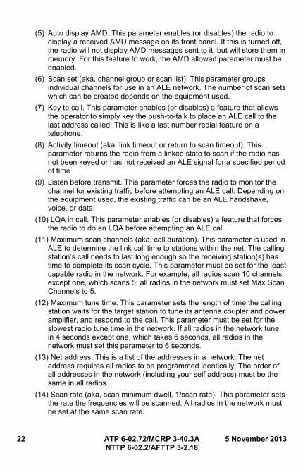
(5) Auto display AMD. This parameter enables (or disables) the radio to display a received AMD message on its front panel. If this is turned off, the radio will not display AMD messages sent to it, but will store them in memory. For this feature to work, the AMD allowed parameter must be enabled.
(6) Scan set (aka, channel group or scan list). This parameter groups individual channels for use in an ALE network. The number of scan sets which can be created depends on the equipment used.
(7) Key to call. This parameter enables (or disables) a feature that allows the operator to simply key the push-to-talk to place an ALE call to the last address called. This is like a last number redial feature on a telephone.
(8) Activity timeout (aka, link timeout or return to scan timeout). This parameter returns the radio from a linked state to scan if the radio has not been keyed or has not received an ALE signal for a specified period of time.
(9) Listen before transmit. This parameter forces the radio to monitor the channel for existing traffic before attempting an ALE call. Depending on the equipment used, the existing traffic can be an ALE handshake, voice, or data.
(10) LQA in call. This parameter enables (or disables) a feature that forces the radio to do an LQA before attempting an ALE call.
(11) Maximum scan channels (aka, call duration). This parameter is used in ALE to determine the link call time to stations within the net. The calling station’s call needs to last long enough so the receiving station(s) has time to complete its scan cycle. This parameter must be set for the least capable radio in the network. For example, all radios scan 10 channels except one, which scans 5; all radios in the network must set Max Scan Channels to 5.
(12) Maximum tune time. This parameter sets the length of time the calling station waits for the target station to tune its antenna coupler and power amplifier, and respond to the call. This parameter must be set for the slowest radio tune time in the network. If all radios in the network tune in 4 seconds except one, which takes 6 seconds, all radios in the network must set this parameter to 6 seconds.
(13) Net address. This is a list of the addresses in a network. The net address requires all radios to be programmed identically. The order of all addresses in the network (including your self address) must be the same in all radios.
(14) Scan rate (aka, scan minimum dwell, 1/scan rate). This parameter sets the rate the frequencies will be scanned. All radios in the network must be set at the same scan rate.
5 November 2013 ATP 6-02.72/MCRP 3-40.3A 23 NTTP 6-02.2/AFTTP 3-2.18
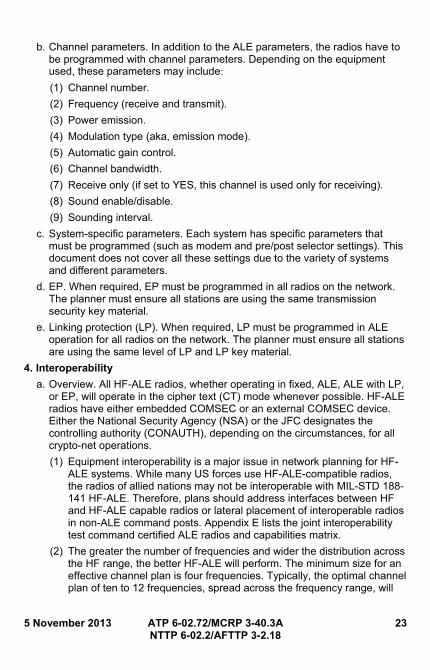
b. Channel parameters. In addition to the ALE parameters, the radios have to be programmed with channel parameters. Depending on the equipment used, these parameters may include: (1) Channel number.
(2) Frequency (receive and transmit).
(3) Power emission.
(4) Modulation type (aka, emission mode).
(5) Automatic gain control.
(6) Channel bandwidth.
(7) Receive only (if set to YES, this channel is used only for receiving).
(8) Sound enable/disable.
(9) Sounding interval.
c. System-specific parameters. Each system has specific parameters that must be programmed (such as modem and pre/post selector settings). This document does not cover all these settings due to the variety of systems and different parameters.
d. EP. When required, EP must be programmed in all radios on the network. The planner must ensure all stations are using the same transmission security key material.
e. Linking protection (LP). When required, LP must be programmed in ALE operation for all radios on the network. The planner must ensure all stations are using the same level of LP and LP key material.
4. Interoperability
a. Overview. All HF-ALE radios, whether operating in fixed, ALE, ALE with LP, or EP, will operate in the cipher text (CT) mode whenever possible. HF-ALE radios have either embedded COMSEC or an external COMSEC device. Either the National Security Agency (NSA) or the JFC designates the controlling authority (CONAUTH), depending on the circumstances, for all crypto-net operations.
(1) Equipment interoperability is a major issue in network planning for HF-ALE systems. While many US forces use HF-ALE-compatible radios, the radios of allied nations may not be interoperable with MIL-STD 188-141 HF-ALE. Therefore, plans should address interfaces between HF and HF-ALE capable radios or lateral placement of interoperable radios in non-ALE command posts. Appendix E lists the joint interoperability test command certified ALE radios and capabilities matrix.
(2) The greater the number of frequencies and wider the distribution across the HF range, the better HF-ALE will perform. The minimum size for an effective channel plan is four frequencies. Typically, the optimal channel plan of ten to 12 frequencies, spread across the frequency range, will
24 ATP 6-02.72/MCRP 3-40.3A 5 November 2013 NTTP 6-02.2/AFTTP 3-2.18
adequately support voice and data HF-ALE operations. As the number of frequencies in the channel plan decreases, the choices of LQA become limited, and may become zero. In addition, as the number of frequencies in the channel plan increases beyond the optimal number (ten to 12 frequencies), the time required to conduct LQA and establish links increases. Aggressively scrutinizing frequency selections and using the optimal number of frequencies per channel plan ensures the best possible HF-ALE performance. Care should be taken to avoid transmitting on frequencies reserved for other uses.
b. HF-ALE addressing and network allocations.
(1) Network allocations are mission dependent; thus when units change their AOR, net planning must address and implement timely updates to minimize disruptions in the operation. The lead Service HF-ALE network manager must contact the JFMO/JSME for frequencies. The HF-ALE network manager will validate the master address list and net assignments prior to generation. After receiving frequency assignments, the network manager will generate the required channel plan, print out paper and prepare an electronic copy to issue and use, and create channel plans needed for operations.
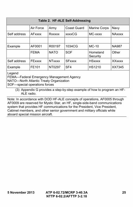
(2) HF-ALE addressing. The HF-ALE network administrator will coordinate HF-ALE addressing in a joint environment. Three to 15 characters can be used as the HF-ALE self address, depending on system parameters. Using fewer characters in the address will optimize the speed of HF-ALE operations. However, due to operational considerations on some networks, it may be practical to use other forms of addressing techniques. In a joint HF-ALE network, an effective technique is to use the letter identifiers for the specific Service, as per table 2. No governing body has been identified in this document for issues with, or deconfliction of, HF-ALE addresses. There is a potential of more than one agency/Service having the same HF-ALE radio address (frequency deconfliction and HF-ALE radio address deconfliction are separate issues).
5 November 2013 ATP 6-02.72/MCRP 3-40.3A 25 NTTP 6-02.2/AFTTP 3-2.18
Table 2. HF-ALE Self-Addressing
Air Force Army Coast Guard Marine Corps Navy
Self address AFxxxx Rxxxxx xxxxCG MC-xxxx NAxxxx
Example AF0001 R00197 1034CG MC-10 NA987
FEMA NATO SOF Homeland Security
Other
Self address FExxxx NTxxxx SFxxxx HSxxxx XXxxxx
Example FE101 NT0297 SF4 HS1210 XX7345
Legend FEMA—Federal Emergency Management Agency NATO—North Atlantic Treaty Organization SOF—special operations forces
(3) Appendix G provides a step-by-step example of how to program an HF-ALE radio.
Note: In accordance with DOD HF-ALE concepts of operations, AF0005 through AF0009 are reserved for Mystic Star, an HF, single-side-band communications system that provides HF communications for the President, Vice President, Cabinet members, and other senior government and military officials while aboard special mission aircraft.

26 ATP 6-02.72/MCRP 3-40.3A 5 November 2013 NTTP 6-02.2/AFTTP 3-2.18
This page intentionally left blank.
5 November 2013 ATP 6-02.72/MCRP 3-40.3A 27 NTTP 6-02.2/AFTTP 3-2.18
Chapter III VERY HIGH FREQUENCY RADIOS
1. Overview
VHF is a term used to describe the 30 to 300 MHz portion of the RF spectrum. This frequency range can provide short-range and long-haul communications. This includes point-to-point, mobile, air-to-ground, and general purpose communications. In the VHF band, there is no usable ground wave and only slight refraction of sky waves by the ionosphere at the lower frequencies. The direct wave LOS provides communications if the transmitting and receiving antennas are elevated high enough above the surface of the Earth.
2. SINCGARS
a. Radio modes of operation (see appendix I for SINCGARS net management). SINCGARS nets can operate in combinations of SC or FH and plain text (PT) or CT.
(1) SC mode uses manually entered frequencies and is not FH or jam resistant.
(2) FH mode is jam resistant, and requires loadsets which consist of hopsets, transmission security keys (TSKs), and net IDs. They may include lockout frequencies and integrated-COMSEC.
(a) A hopset, or lockout, is the set of frequencies on which an FH net hops. Hopsets are electronically loaded and stored in the radio.
(b) A TSK establishes a pseudo-random pattern in which the frequencies will be used.
(c) Net IDs establish the starting point within the pseudo-random pattern and are often allocated to specific units.
(d) TOD synchronizes the FH. Every effort must be made to maintain a standard TOD within the operating theater. GPS time is recommended.
b. Loadset distribution (FH and COMSEC data).
(1) A SINCGARS radio loadset consists of FH and COMSEC data. Only designated operators may transfer FH and COMSEC data physically from device to device, transmit the data electronically, or send it using a combination of physical and electronic means. The lowest operational echelon will normally distribute and store loadsets consistent with the availability of fill devices, security arrangements, and operational needs.
(2) The CONAUTH and JTF J-6 provide COMSEC and FH data to users. However, the CONAUTH provides only the amount necessary to satisfy operational requirements consistent with distribution capabilities. Organizations will deploy with the amount of data necessary to satisfy initial operational requirements consistent with distribution capabilities. Storing reserve loadsets at selected echelons facilitates rapid
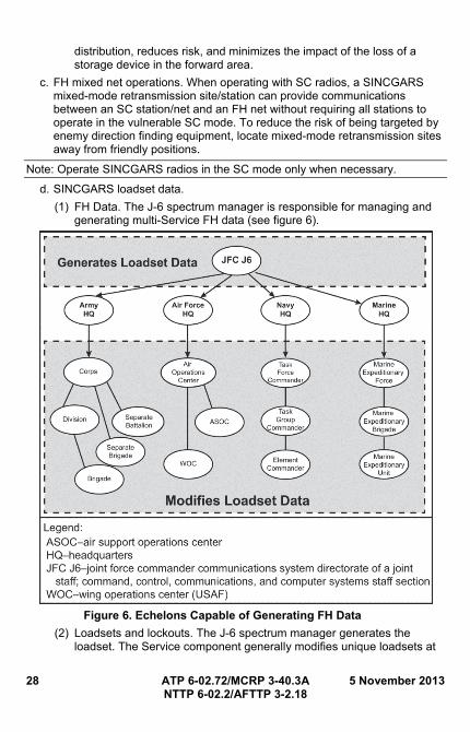
28 ATP 6-02.72/MCRP 3-40.3A 5 November 2013 NTTP 6-02.2/AFTTP 3-2.18
distribution, reduces risk, and minimizes the impact of the loss of a storage device in the forward area.
c. FH mixed net operations. When operating with SC radios, a SINCGARS mixed-mode retransmission site/station can provide communications between an SC station/net and an FH net without requiring all stations to operate in the vulnerable SC mode. To reduce the risk of being targeted by enemy direction finding equipment, locate mixed-mode retransmission sites away from friendly positions.
Note: Operate SINCGARS radios in the SC mode only when necessary.
d. SINCGARS loadset data.
(1) FH Data. The J-6 spectrum manager is responsible for managing and generating multi-Service FH data (see figure 6).
Figure 6. Echelons Capable of Generating FH Data
(2) Loadsets and lockouts. The J-6 spectrum manager generates the loadset. The Service component generally modifies unique loadsets at
5 November 2013 ATP 6-02.72/MCRP 3-40.3A 29 NTTP 6-02.2/AFTTP 3-2.18
the corps- or Service-equivalent level. To maximize effectiveness of FH, loadsets should use the largest possible number of frequencies in the SINCGARS frequency range. This FH range and the user frequency requirements determine the assignment of loadsets. After the spectrum manager generates loadsets, TSKs and net IDs are assigned. If a force’s AOR or task organization changes, it is the responsibility of the higher headquarters to pass the required loadset to the moving unit.
(a) The larger the number of frequencies and wider the distribution across the SINCGARS frequency range, the better SINCGARS will perform when in FH mode. Loadset performance is a function of many factors, including interference from friendly emitters, other electromagnetic sources, and the enemy’s electronic attack capability.
(b) The SINCGARS radio can store a unique loadset, and all other FH and COMSEC data, in each channel preset. The NCS or station designated as FH-M should transmit on each FH net a minimum of every four hours to keep all stations active on the net.
(3) Manual setting. radio operators may manually enter time into most SINCGARS-compatible radios using the keypad. Operators update sync time by contact with their NCS (FH-M function), receipt of an ERF via the defense advanced GPS receiver, or manually changing the sync time in the radio by using the keypad.
(4) Julian date. SINCGARS radios require a two-digit Julian date. On Julian days 100-365, any radio that uses a two digit Julian date drops the first digit (e.g., day 100 is entered into the radio as day 00).
(5) COMSEC data. All SINCGARS radios, whether SC or FH capable, will operate in the CT mode whenever possible. SINCGARS radios have either integrated COMSEC or can use an external COMSEC device. The JFC normally designates the CONAUTH for all crypto-net operations, and the J-6 will provide overall staff supervision. COMSEC data includes traffic encryption key (TEK) and key encryption key (KEK).
e. SINCGARS data distribution within Services and components.
(1) Army forces (ARFOR). (See figure 7.) The Army component CONAUTH receives and disseminates the FH and COMSEC data to subordinate echelons. The CONAUTH is the commander of the organization, or activity, responsible for directing the establishment and operation of a cryptographic network (cryptonet); and for managing the operational use and control of keying material assigned to the cryptonet. The commander may delegate CONAUTH responsibilities to a subordinate in writing. The CONAUTH should be organizationally senior to cryptonet members, have the staff and expertise to perform essential management functions, and have the authority to ensure instructions
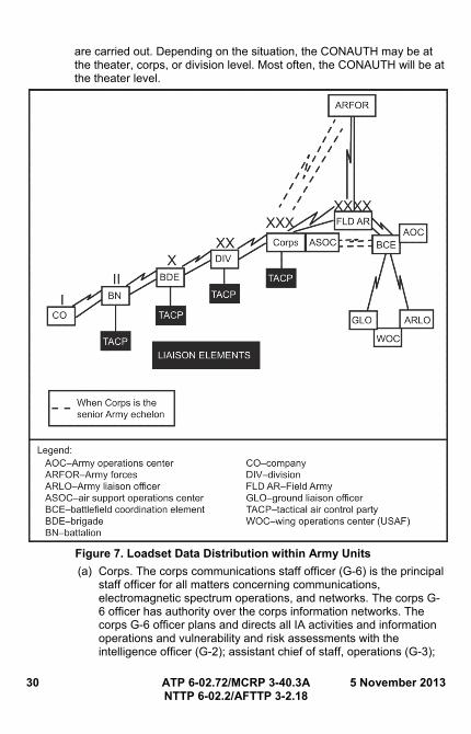
30 ATP 6-02.72/MCRP 3-40.3A 5 November 2013 NTTP 6-02.2/AFTTP 3-2.18
are carried out. Depending on the situation, the CONAUTH may be at the theater, corps, or division level. Most often, the CONAUTH will be at the theater level.
Figure 7. Loadset Data Distribution within Army Units
(a) Corps. The corps communications staff officer (G-6) is the principal staff officer for all matters concerning communications, electromagnetic spectrum operations, and networks. The corps G-6 officer has authority over the corps information networks. The corps G-6 officer plans and directs all IA activities and information operations and vulnerability and risk assessments with the intelligence officer (G-2); assistant chief of staff, operations (G-3);
5 November 2013 ATP 6-02.72/MCRP 3-40.3A 31 NTTP 6-02.2/AFTTP 3-2.18
assistant chief of staff, information engagement (G-7); operational chain of command; and the Service Theater Network Operations Security Center (STNOSC). The corps G-6 officer employs a fully integrated NOSC providing network operations (NETOPS) functions for the corps. All corps signal elements must coordinate with the NOSC during the engineering, installation, operation, maintenance, and defense of the corps information network. The corps NOSC:
• Monitors, manages, and ensures implementation of enterprise system management/network management, information dissemination management/content staging, and IA/computer network defense (CND) activities in coordination with the operational chain of command, STNOSC, and subordinate organizations.
• Coordinates operational procedures and requirements for IA/CND and information systems security with the operational chain of command and supporting regional computer emergency response team.
• Orders and accounts for all forms of COMSEC material, including storing keys in encrypted form, performing key generation (corps’ TEK and KEK), and automatic key distribution.
• Generates signal of interest (SOI) data, and FH data (corps-wide loadsets, net ID, and TSK).
(b) Division. The division G-6 is responsible employing a fully integrated NOSC providing NETOPS functions for the division. All division signal elements must coordinate with the division NOSC during the engineering, installation, operation, maintenance, and defense of the division information network. The division NOSC: • Monitors, manages, and ensures implementation of enterprise
system/network management, information dissemination management/content staging, and IA/CND activities in accordance with the operational chain of command, STNOSC, and subordinate organizations.
• Coordinates operational procedures and requirements for IA/CND and ISS with the supporting Army Service component command regional computer emergency response team.
• Orders and accounts for all forms of COMSEC material, including storing keys in encrypted form, performing key generation (division TEKs and KEKs), and automatic key distribution.
• Generates and merges SOI data, and generates FH data (net IDs and division TSKs).
32 ATP 6-02.72/MCRP 3-40.3A 5 November 2013 NTTP 6-02.2/AFTTP 3-2.18
• Performs COMSEC material accounting functions and communicates with other COMSEC elements.
• Coordinates operational procedures and requirements for IA/CND and ISS with the operational chain of command and supporting regional computer emergency response team.
(c) Army contingency planning.
• When Army component staffs are energized for a possible contingency, they will begin planning and preparing for operations simultaneously. Once the task organization is identified, commanders fine tune and determine the specific elements needed. Concurrently, J-6 frequency managers coordinate with higher-level frequency managers to obtain usable frequencies. Mission specific TSKs are generated and disseminated through the joint automated communication-electronics operating instructions system (JACS) or Revised Battlefield Electronic Communications, Electronics, Intelligence, and Operations (CEIO) System (RBECS) managers to the supporting forces. A separate message indicates specific TSK usage.
• COMSEC custodians coordinate COMSEC key needs and produce a COMSEC callout message that identifies specific keys for joint, ARFOR, corps, or division use. ARFOR subordinate units identify a specific net requirement and the master net list is compiled by higher headquarters.
• Upon receipt of approved frequencies from J-6, the ARFOR G-6 generates SOIs for use by ARFOR. In support of joint operations, Army JACS or RBECS managers pass a list of specific units and nets to the J-6. Once the J-6 provides FH data to the G-6, the G-6 disseminates the FH data to subordinate commands. Each level then prepares loadsets. At this point, files can be transferred back to the next higher level for archiving. Finalization is effected upon receipt of the COMSEC callout message and specific TSK use message. Prepared SOIs may be passed to subordinate units by secure electronic or physical means.
Note: SOI, COMSEC data, TSKs, and net ID assignments generation normally does not occur below the division/separate brigade level. When authorized to do so, brigade and separate battalion lightweight computer unit operators may generate TEKs to meet emergency requirements. When TEKs are generated at a lower echelon, they are forwarded through higher headquarters to the joint force command.
(2) Marine Corps forces (MARFOR). (Figure 8.) The Marine Corps uses JACS as the standard system for generating, distributing, and storing
5 November 2013 ATP 6-02.72/MCRP 3-40.3A 33 NTTP 6-02.2/AFTTP 3-2.18
communications-electronics operating instructions (CEOI) information at all levels of command. To employ the communications assets of the Marine air-ground task force (MAGTF) effectively, the spectrum manager also uses the Systems Planning, Engineering, and Evaluation Device software to create accurate terrain analysis and wave propagation studies that allow for selecting the optimum antenna sites. The Marine Corps uses the AN/CYZ-10 Data Transfer Device (ANCD) and AN/PYQ-10 Simple Key Loader (SKL) to transfer, store, and fill SINCGARS TEK, KEK and FH data at all levels. The ANCD/SKL uses JACS radio data system (RDS) software to fill SINCGARS capable radios’ single-channel radio electronic counter measure package (CSEP) which then is used to load the AN/ARC-210. Marine aircraft groups using the AN/ARC-210 radio will be required to convert JACS loadset files into CSEP/ARC-210 data using the ARC-210 fill program (AFP) software. AFP also allows the entry of HQ and SC data for the ARC-210. AFP software has the same hardware requirements as JACS.
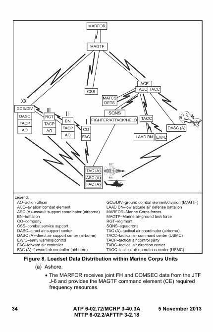
34 ATP 6-02.72/MCRP 3-40.3A 5 November 2013 NTTP 6-02.2/AFTTP 3-2.18
Figure 8. Loadset Data Distribution within Marine Corps Units
(a) Ashore.
• The MARFOR receives joint FH and COMSEC data from the JTF J-6 and provides the MAGTF command element (CE) required frequency resources.
5 November 2013 ATP 6-02.72/MCRP 3-40.3A 35 NTTP 6-02.2/AFTTP 3-2.18
• The MAGTF CE generates MAGTF FH data, publishes COMSEC data, and allocates net IDs for all major subordinate commands (MSCs) and supporting units.
• The ground combat element (GCE) receives all joint and MAGTF FH data from the MAGTF CE. The GCE is capable of loadset generation down to the regimental level (implemented only when directed).
• The aviation combat element (ACE) receives all joint and MAGTF FH data from the MAGTF CE. The MAGTF CE provides special loadset files for the AN/ARC-210. The ACE is capable of loadset generation down to the group level (implemented only when directed).
• The MAGTF Marine logistics group (MLG)/combat logistics regiment (CLR) receives all joint and MAGTF FH data from the MAGTF CE. The MLG/CLR is capable of loadset generation at the MLG/CLR headquarters (implemented only when directed).
(b) Afloat.
• Navy forces (NAVFOR) provide the MAGTF CE with required frequency resources and joint FH data.
• The MAGTF CE generates MAGTF FH data, publishes COMSEC data, and allocates net IDs for all MSCs and supporting units.
• The GCE receives all joint and MAGTF FH data from the MAGTF CE. The GCE is capable of loadset generation down to the regimental level (implemented only when directed).
• The ACE receives all joint and MAGTF FH data from the MAGTF CE. It provides loadset files for AN/ARC-210 users. The ACE is capable of loadset generation down to the group level (implemented only when directed).
• The MLG/CLR receives all joint and MAGTF FH data from the MAGTF CE. The combat service support is capable of loadset generation at the MLG/CLR headquarters (implemented only if directed).
(3) NAVFOR. Distribution of FH and COMSEC data within NAVFOR depends on the task organization. The initial implementation of SINCGARS in the Navy is primarily intended to support amphibious warfare operations. In an amphibious battle group scenario, the communications staff of the commander, amphibious task force (CATF) acts as the deconfliction point for FH and COMSEC data received from the MAGTF, elements of the amphibious task force, the composite warfare commander (CWC), the amphibious ready group commander, and carrier strike group (CSG) commander. Figure 9 illustrates this bottom-up flow of data to the deconfliction point and the top-down
36 ATP 6-02.72/MCRP 3-40.3A 5 November 2013 NTTP 6-02.2/AFTTP 3-2.18
dissemination of deconflicted data to every SINCGARS equipped element involved in the operation. In a conventional CSG scenario, the CWC/officer in tactical command (OTC) communications staff will act as the deconfliction point for FH and COMSEC data.
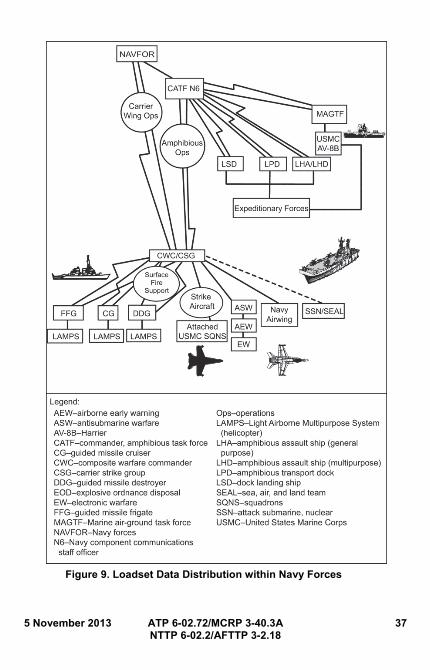
5 November 2013 ATP 6-02.72/MCRP 3-40.3A 37 NTTP 6-02.2/AFTTP 3-2.18
Figure 9. Loadset Data Distribution within Navy Forces
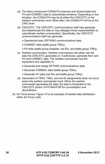
38 ATP 6-02.72/MCRP 3-40.3A 5 November 2013 NTTP 6-02.2/AFTTP 3-2.18
(a) The Navy component CONAUTH receives and disseminates the FH and COMSEC data to subordinate echelons. Depending on the situation, the CONAUTH may be at either the CWC/OTC or the warfare commander level. Most often, the CONAUTH will be at the CWC level.
(b) CWC/OTC. The CWC/OTC communications staff may generate and disseminate the data or may delegate those responsibilities to subordinate warfare commanders. Specifically, the CWC/OTC communications staff can generate: • Operational task (OPTASK) communications data.
• COMSEC data (battle group TEKs).
• FH data (battle group loadsets, net IDs, and battle group TSKs).
(c) Warfare commanders. Warfare commanders will either use the data the CWC/OTC generates or, if authorized, generate their own FH and COMSEC data. The warfare commander has the equipment and capability to: • Generate and merge OPTASK communications data.
• Generate COMSEC data (battle group TEKs).
• Generate FH data (net IDs and battle group TSKs).
(d) Generation of TEKs, TSKs, and net ID assignments does not occur below the warfare commander level. When the warfare commander generates the data, the data is forwarded to the CWC/OTC and/or CATF/NAVFOR for consolidation and deconfliction.
(4) Air Force forces. Figure 10 is an example of loadset data distribution within Air Force units.
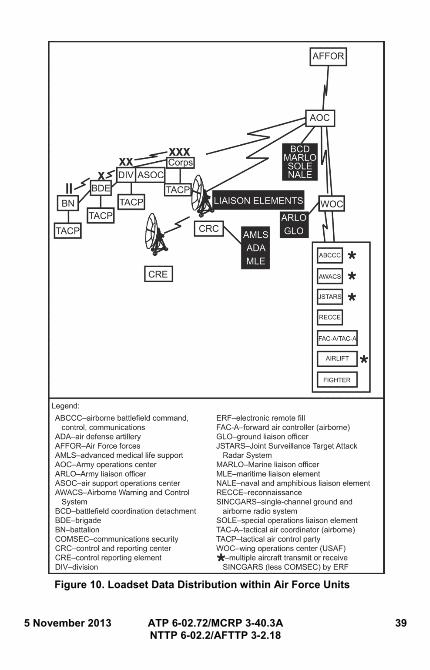
5 November 2013 ATP 6-02.72/MCRP 3-40.3A 39 NTTP 6-02.2/AFTTP 3-2.18
Figure 10. Loadset Data Distribution within Air Force Units
40 ATP 6-02.72/MCRP 3-40.3A 5 November 2013 NTTP 6-02.2/AFTTP 3-2.18
(a) Air operations center (AOC). The AOC is the operations control agency for the joint force air component. The AOC will provide overall management of SINCGARS net data for the Air Force components using Air Force key data management system (AFKDMS), and coordinate the SINCGARS net data with other Service components via the air tasking order (ATO). In this capacity, the AOC: • Provides the joint force land component commander (JFLCC)
communications staff with the total air component SINCGARS net requirements for close air support (CAS), combat search and rescue (CSAR), and joint suppression of enemy air defense.
• Receives initial and follow-on CEOI/SOI from the JFLCC (including the SINCGARS FH and associated COMSEC data) and distributes it to air component users (deployable radar, control and reporting center (CRC), MAGTF ACE CSG, CWC/OTC, etc.).
• Provides guidance to Air Force SINCGARS users regarding loading and employing SINCGARS nets.
Note: The AOC, in conjunction with generating the ATO, will identify the particular SINCGARS net data, TSKs, and COMSEC key identifiers, call signs, and call words for the specific CAS mission tasking. In addition, the AOC will identify both the SINCGARS data required by the CRC and the deployable radar. The actual SINCGARS FH data and communications identifiers will be transferred to the wing operations center (WOC) via the Wing Command and Control System (WCCS).
(b) CRC. The CRC will develop and distribute loadsets for CRC and deployable radar SINCGARS assets.
(c) Air support operations center (ASOC). The ASOC is the corps’ focal point for execution of US Air Force air support missions in support of US Army ground forces. In this capacity, the ASOC: • Coordinates Air Force agreements with the Army for ANCDs and
SINCGARS data for all tactical air control party (TACP) SINCGARS radio assets. The Army agreed to provide the RDS for installation on the TACP ANCDs. Also, the Army agreed to provide the SINCGARS CEOI/SOI to the aligned TACP units.
• Ensures SINCGARS net requirements for immediate CAS are correctly specified. Immediate CAS will be conducted on a uniquely specified standing net.
(d) WOC. The WOC executes the ATO as published by the AOC. Operations personnel of tasked units configure mission sets from the SINCGARS data and the linking SINCGARS identifiers contained in the ATO to support the specified mission. The WOC:
5 November 2013 ATP 6-02.72/MCRP 3-40.3A 41 NTTP 6-02.2/AFTTP 3-2.18
• Develops procedures for integrating the construction of mission sets into the wing mission planning process using the WCCS and the AFKDMS.
• Develops and implements a SINCGARS standard loading scheme.
• Develops and implements procedures for transferring loadsets to the key data system ANCD at the squadron/unit level and for subsequent loading of SINCGARS radios in specific aircraft assigned to the mission.
(e) Special tasking operations. Pre-mission planning requirements for small-scale, contingency, unilateral, and inter-Service operations demand the operational commander provide all SINCGARS FH and COMSEC fill data or identifiers for Air Force assets before deployment. Physical and electronic distribution of the SINCGARS and COMSEC communications packages should be accomplished as early as possible using the best means available for the particular situation (i.e., secure telephone equipment, SATCOM, inter-theater COMSEC package, and/or ERF).

42 ATP 6-02.72/MCRP 3-40.3A 5 November 2013 NTTP 6-02.2/AFTTP 3-2.18
This page intentionally left blank.
5 November 2013 ATP 6-02.72/MCRP 3-40.3A 43 NTTP 6-02.2/AFTTP 3-2.18
Chapter IV ULTRAHIGH FREQUENCY RADIOS
1. Overview
UHF is a term used to describe the 300 MHz to 3 GHz portion of the RF spectrum. This frequency range can provide short-range and long-haul communications. In the UHF band, direct wave is used for transmissions (15 to 100 miles). Communications are limited to a short distance beyond the horizon. Lack of static and fading in these bands makes LOS reception satisfactory. Highly directional antennas can be used to concentrate the beam of RF energy, thus increasing the signal intensity. UHF satellite transmissions can cover thousands of miles, depending on altitude, power, and antenna configuration. UHF radios and systems that play an important role in the network-centric warfare are the EPLRS, blue force tracking (BFT) near term digital radio, multifunctional information distribution system (MIDS), and the Joint Tactical Information Distribution System (JTIDS). These systems are employed to provide ground-to-air, ship-to shore, and multinational communications.
2. EPLRS
a. Overview.
(1) EPLRS is an enabler for network-centric warfare. EPLRS supports the Army’s transformation brigades and is interoperable with the US Air Force, Marine Corps, and Navy. EPLRS mobile networks are used by Army Battle Command System(s) (ABCS) and Force Battle Command Brigade and Below (FBCB2) host computers for situational awareness (SA) and C2. The situation awareness data link (SADL) integrates US Air Force CAS aircraft with the digitized battlefield via EPLRS. With its inherent position and status reporting for SA, the SADL provides an effective solution to the long-standing, air-to-ground combat ID problem.
(2) EPLRS is a wireless tactical communications system that automatically routes and delivers messages, enabling accurate and timely computer-to-computer communications on the battlefield. Using time division multiple access (TDMA), FH, and error correction coding technologies, the EPLRS provides the means for high-speed horizontal and vertical information distribution. The system, comprised of many radios and one or more network controllers, provides multiple concurrent communications channels.
(3) A typical EPLRS system consists of 800 radio sets within a Stryker Brigade Combat Team. Radios are networked to provide automatic, secure, jam-resistant relay of host-to-host data throughout the network. The EPLRS has automatic relay capabilities that are transparent to the user for beyond LOS coverage.
(4) The network controller provides integral position location and navigation services to the user, and secure over-the-air-rekey functionality. EPLRS provides programmable waveforms, selectable data rates, and multiple
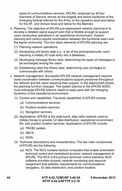
44 ATP 6-02.72/MCRP 3-40.3A 5 November 2013 NTTP 6-02.2/AFTTP 3-2.18
types of communications services. EPLRS, employed by all four branches of Service, serves as the brigade and below backbone of the emerging tactical Internet for the Army, to the squadron level and below for the AF, and division level and below for the Marines.
b. Planning. The objective of EPLRS pre-deployment network planning is to develop a detailed signal support plan that is flexible enough to support users conducting operations in an operational environment. System planning and control require coordination between the functional users and the signal community. The four basic elements of EPLRS planning are:
(1) Planning network operations.
(2) Developing unit library data (i.e., a list of the participants/units; each requiring a military ID code entry into a database).
(3) Developing message library data, determining the types of messages to be exchanged among the users.
(4) Establishing need line library data, determining user privileges to communicate with others.
c. Network management. Successful EPLRS network management requires close coordination between communications support personnel throughout the network and the users requiring their support. In the deployment phase, the planning function changes. The system planner in the EPLRS NOSC must anticipate EPLRS network needs to keep pace with the changing dynamics of the operational environment.
(1) Context and capabilities. Top-level capabilities of EPLRS include: (a) Communications services.
(b) Position location services.
(c) Navigation services.
(2) Applications. EPLRS is the wide-band, data radio network used by military forces to provide C2 data distribution, operational environment SA, and position location services. Applications of EPLRS include:
(a) FBCB2 system.
(b) ABCS.
(c) SADL.
(3) Technical descriptions and characteristics. The two main components of EPLRS are the following.
(a) NCS. The NCS contains tactical computers that enable automated technical control and centralized dynamic network management of EPLRS. The NCS is the primary technical control interface. NCS software provides dynamic network monitoring and resource assignment that satisfies requirements for communications, navigation, ID data distribution, and position location.
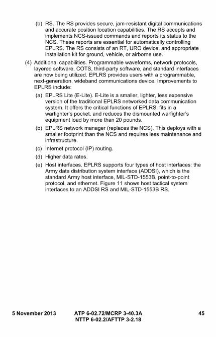
5 November 2013 ATP 6-02.72/MCRP 3-40.3A 45 NTTP 6-02.2/AFTTP 3-2.18
(b) RS. The RS provides secure, jam-resistant digital communications and accurate position location capabilities. The RS accepts and implements NCS-issued commands and reports its status to the NCS. These reports are essential for automatically controlling EPLRS. The RS consists of an RT, URO device, and appropriate installation kit for ground, vehicle, or airborne use.
(4) Additional capabilities. Programmable waveforms, network protocols, layered software, COTS, third-party software, and standard interfaces are now being utilized. EPLRS provides users with a programmable, next-generation, wideband communications device. Improvements to EPLRS include:
(a) EPLRS Lite (E-Lite). E-Lite is a smaller, lighter, less expensive version of the traditional EPLRS networked data communication system. It offers the critical functions of EPLRS, fits in a warfighter’s pocket, and reduces the dismounted warfighter’s equipment load by more than 20 pounds.
(b) EPLRS network manager (replaces the NCS). This deploys with a smaller footprint than the NCS and requires less maintenance and infrastructure.
(c) Internet protocol (IP) routing.
(d) Higher data rates.
(e) Host interfaces. EPLRS supports four types of host interfaces: the Army data distribution system interface (ADDSI), which is the standard Army host interface, MIL-STD-1553B, point-to-point protocol, and ethernet. Figure 11 shows host tactical system interfaces to an ADDSI RS and MIL-STD-1553B RS.
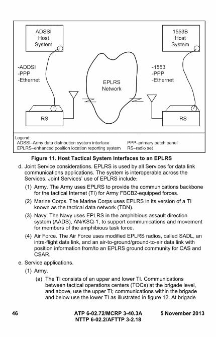
46 ATP 6-02.72/MCRP 3-40.3A 5 November 2013 NTTP 6-02.2/AFTTP 3-2.18
Figure 11. Host Tactical System Interfaces to an EPLRS
d. Joint Service considerations. EPLRS is used by all Services for data link communications applications. The system is interoperable across the Services. Joint Services’ use of EPLRS include: (1) Army. The Army uses EPLRS to provide the communications backbone
for the tactical Internet (TI) for Army FBCB2-equipped forces.
(2) Marine Corps. The Marine Corps uses EPLRS in its version of a TI known as the tactical data network (TDN).
(3) Navy. The Navy uses EPLRS in the amphibious assault direction system (AADS), AN/KSQ-1, to support communications and movement for members of the amphibious task force.
(4) Air Force. The Air Force uses modified EPLRS radios, called SADL, an intra-flight data link, and an air-to-ground/ground-to-air data link with position information from/to an EPLRS ground community for CAS and CSAR.
e. Service applications.
(1) Army.
(a) The TI consists of an upper and lower TI. Communications between tactical operations centers (TOCs) at the brigade level, and above, use the upper TI; communications within the brigade and below use the lower TI as illustrated in figure 12. At brigade
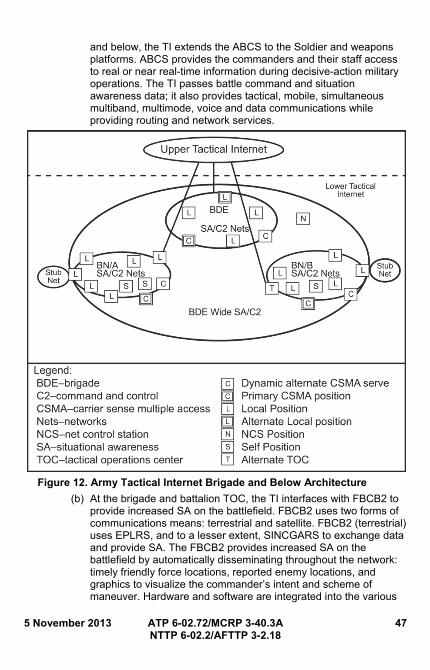
5 November 2013 ATP 6-02.72/MCRP 3-40.3A 47 NTTP 6-02.2/AFTTP 3-2.18
and below, the TI extends the ABCS to the Soldier and weapons platforms. ABCS provides the commanders and their staff access to real or near real-time information during decisive-action military operations. The TI passes battle command and situation awareness data; it also provides tactical, mobile, simultaneous multiband, multimode, voice and data communications while providing routing and network services.
Figure 12. Army Tactical Internet Brigade and Below Architecture
(b) At the brigade and battalion TOC, the TI interfaces with FBCB2 to provide increased SA on the battlefield. FBCB2 uses two forms of communications means: terrestrial and satellite. FBCB2 (terrestrial) uses EPLRS, and to a lesser extent, SINCGARS to exchange data and provide SA. The FBCB2 provides increased SA on the battlefield by automatically disseminating throughout the network: timely friendly force locations, reported enemy locations, and graphics to visualize the commander’s intent and scheme of maneuver. Hardware and software are integrated into the various
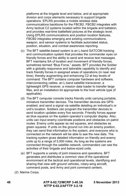
48 ATP 6-02.72/MCRP 3-40.3A 5 November 2013 NTTP 6-02.2/AFTTP 3-2.18
platforms at the brigade level and below, and at appropriate division and corps elements necessary to support brigade operations. EPLRS provides a mobile wireless data communications backbone for the FBCB2. FBCB2 integrates with Army tactical C2 systems located within the brigade and battalion, and provides real-time battlefield pictures at the strategic level. Using EPLRS communications and position location features, FBCB2 integrates emerging and existing communications, weapon, and sensor systems to facilitate automated status, position, situation, and combat awareness reporting.
(c) The BFT satellite-based system is an L-band SATCOM tracking and communication system that provides the commander eyes on friendly forces and the ability to send and receive text messages. BFT maintains SA of location and movement of friendly forces, sometimes termed “Blue Force,” assets. BFT provides the Soldier with a globally responsive and tailorable capability to identify and track friendly forces in assigned areas of operations (in near real time), thereby augmenting and enhancing C2 at key levels of command. The BFT contains computer hardware and software, interconnecting cables, an L-band satellite transceiver, a lightweight GPS receiver, a mission data loader to transfer large files, and an installation kit appropriate to the host vehicle type (if applicable).
(d) The BFT computer console tracks friendly units carrying portable, miniature transmitter devices. The transmitter devices are GPS-enabled, and send a signal via satellite detailing an individual’s or unit’s location. Soldiers can program the transmitter devices to send location updates every five seconds. Friendly forces appear as blue squares on the system operator’s computer display. Also, units can input enemy coordinate positions and obstacles on patrol routes. Enemy units appear as red squares, and obstacles as green squares. If units on the ground run into an enemy position, they can send that information to the system, and everyone who is connected on the network will be able to see the new data. The tracking system gives detailed information on friendly and enemy units up to a range of 5,000 miles. As long as the systems are connected through the satellite network, commanders can see the activities of their brigade and below-sized units.
(e) BFT supports a variety of joint missions and operations. BFT generates and distributes a common view of the operational environment at the tactical and operational levels, identifying and sharing that view with ground vehicles, rotary-wing aircraft, command posts, and Army and joint command centers.
(2) Marine Corps.
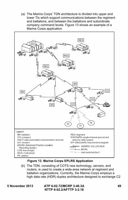
5 November 2013 ATP 6-02.72/MCRP 3-40.3A 49 NTTP 6-02.2/AFTTP 3-2.18
(a) The Marine Corps’ TDN architecture is divided into upper and lower TIs which support communications between the regiment and battalions, and between the battalions and subordinate company command levels. Figure 13 shows an example of a Marine Corps application.
Figure 13. Marine Corps EPLRS Application
(b) The TDN, consisting of COTS new technology, servers, and routers, is used to create a wide-area network at regiment and battalion organizations. Currently, the Marine Corps employs a high data rate (HDR) duplex architecture designed to exchange C2
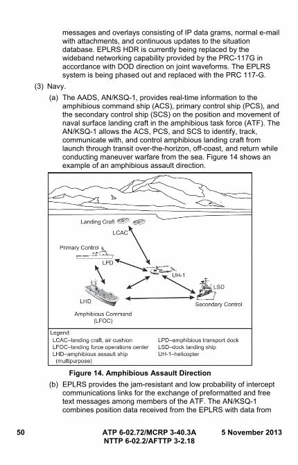
50 ATP 6-02.72/MCRP 3-40.3A 5 November 2013 NTTP 6-02.2/AFTTP 3-2.18
messages and overlays consisting of IP data grams, normal e-mail with attachments, and continuous updates to the situation database. EPLRS HDR is currently being replaced by the wideband networking capability provided by the PRC-117G in accordance with DOD direction on joint waveforms. The EPLRS system is being phased out and replaced with the PRC 117-G.
(3) Navy.
(a) The AADS, AN/KSQ-1, provides real-time information to the amphibious command ship (ACS), primary control ship (PCS), and the secondary control ship (SCS) on the position and movement of naval surface landing craft in the amphibious task force (ATF). The AN/KSQ-1 allows the ACS, PCS, and SCS to identify, track, communicate with, and control amphibious landing craft from launch through transit over-the-horizon, off-coast, and return while conducting maneuver warfare from the sea. Figure 14 shows an example of an amphibious assault direction.
Figure 14. Amphibious Assault Direction
(b) EPLRS provides the jam-resistant and low probability of intercept communications links for the exchange of preformatted and free text messages among members of the ATF. The AN/KSQ-1 combines position data received from the EPLRS with data from
5 November 2013 ATP 6-02.72/MCRP 3-40.3A 51 NTTP 6-02.2/AFTTP 3-2.18
the GPS and existing ship and landing craft equipment at ranges up to 100 nautical miles. During the ship-to-shore phase of the amphibious assault, EPLRS radios installed in the landing force operations center will link the landing force commander with other Marine Corps command elements ashore. EPLRS radios installed on the landing craft, air cushion augmented by airborne relays (as required) provide necessary connectivity.
(4) Air Force.
(a) SADL is the integration of the modified EPLRS radio with a MIL-STD-1553B host interface and aircraft avionics over the aircraft MIL-STD-1553B multiplex bus. It allows data from other SADL equipped fighters and ground EPLRS locations to be seen in cockpit displays. Figure 15 shows an example of a SADL network.
Figure 15. Situation Awareness Data Link Network
(b) The SADL air-to-air network, consisting of two to sixteen members, is self-reliant and functions independently of the presence or absence of a ground-based NCS. Net members share fighter positions, target positions, and weapons and fuel status. NSA-
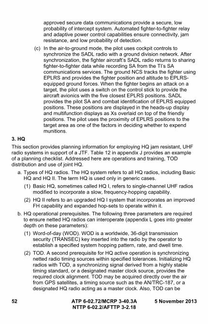
52 ATP 6-02.72/MCRP 3-40.3A 5 November 2013 NTTP 6-02.2/AFTTP 3-2.18
approved secure data communications provide a secure, low probability of intercept system. Automated fighter-to-fighter relay and adaptive power control capabilities ensure connectivity, jam resistance, and low probability of detection.
(c) In the air-to-ground mode, the pilot uses cockpit controls to synchronize the SADL radio with a ground division network. After synchronization, the fighter aircraft’s SADL radio returns to sharing fighter-to-fighter data while recording SA from the TI’s SA communications services. The ground NCS tracks the fighter using EPLRS and provides the fighter position and altitude to EPLRS-equipped ground forces. When the fighter begins an attack on a target, the pilot uses a switch on the control stick to provide the aircraft avionics with the five closest EPLRS positions. SADL provides the pilot SA and combat identification of EPLRS equipped positions. These positions are displayed in the heads-up display and multifunction displays as Xs overlaid on top of the friendly positions. The pilot uses the proximity of EPLRS positions to the target area as one of the factors in deciding whether to expend munitions.
3. HQ
This section provides planning information for employing HQ jam resistant, UHF radio systems in support of a JTF. Table 12 in appendix J provides an example of a planning checklist. Addressed here are operations and training, TOD distribution and use of joint HQ.
a. Types of HQ radios. The HQ system refers to all HQ radios, including Basic HQ and HQ II. The term HQ is used only in generic cases.
(1) Basic HQ, sometimes called HQ I, refers to single-channel UHF radios modified to incorporate a slow, frequency-hopping capability.
(2) HQ II refers to an upgraded HQ I system that incorporates an improved FH capability and expanded hop-sets to operate within it.
b. HQ operational prerequisites. The following three parameters are required to ensure netted HQ radios can interoperate (appendix L goes into greater depth on these parameters):
(1) Word-of-day (WOD). WOD is a worldwide, 36-digit transmission security (TRANSEC) key inserted into the radio by the operator to establish a specified system hopping pattern, rate, and dwell time.
(2) TOD. A second prerequisite for HQ active operation is synchronizing netted radio timing sources within specified tolerances. Initializing HQ radios with TOD, a synchronizing signal derived from a highly stable timing standard, or a designated master clock source, provides the required clock alignment. TOD may be acquired directly over the air from GPS satellites, a timing source such as the AN/TRC-187, or a designated HQ radio acting as a master clock. Also, TOD can be
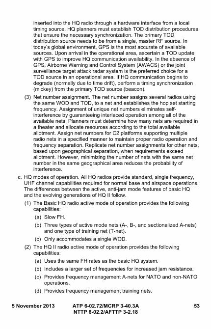
5 November 2013 ATP 6-02.72/MCRP 3-40.3A 53 NTTP 6-02.2/AFTTP 3-2.18
inserted into the HQ radio through a hardware interface from a local timing source. HQ planners must establish TOD distribution procedures that ensure the necessary synchronization. The primary TOD distribution source needs to be from a single, master RF source. In today’s global environment, GPS is the most accurate of available sources. Upon arrival in the operational area, ascertain a TOD update with GPS to improve HQ communication availability. In the absence of GPS, Airborne Warning and Control System (AWACS) or the joint surveillance target attack radar system is the preferred choice for a TOD source in an operational area. If HQ communication begins to degrade (normally due to time drift), perform a timing synchronization (mickey) from the primary TOD source (beacon).
(3) Net number assignment. The net number assigns several radios using the same WOD and TOD, to a net and establishes the hop set starting frequency. Assignment of unique net numbers eliminates self-interference by guaranteeing interlaced operation among all of the available nets. Planners must determine how many nets are required in a theater and allocate resources according to the total available allotment. Assign net numbers for C2 platforms supporting multiple radio nets in a specified manner to maintain proper radio operation and frequency separation. Replicate net number assignments for other nets, based upon geographical separation, when requirements exceed allotment. However, minimizing the number of nets with the same net number in the same geographical area reduces the probability of interference.
c. HQ modes of operation. All HQ radios provide standard, single frequency, UHF channel capabilities required for normal base and airspace operations. The differences between the active, anti-jam mode features of basic HQ and the evolving generations of HQ II follow.
(1) The Basic HQ radio active mode of operation provides the following capabilities:
(a) Slow FH.
(b) Three types of active mode nets (A-, B-, and sectionalized A-nets) and one type of training net (T-net).
(c) Only accommodates a single WOD.
(2) The HQ II radio active mode of operation provides the following capabilities:
(a) Uses the same FH rates as the basic HQ system.
(b) Includes a larger set of frequencies for increased jam resistance.
(c) Provides frequency management A-nets for NATO and non-NATO operations.
(d) Provides frequency management training nets.
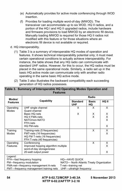
54 ATP 6-02.72/MCRP 3-40.3A 5 November 2013 NTTP 6-02.2/AFTTP 3-2.18
(e) Automatically provides for active mode conferencing through WOD insertion.
(f) Provides for loading multiple word-of-day (MWOD). The transceiver can accommodate up to six WOD. HQ II radios, and a portion of the HQ I and HQ II upgraded radios, include hardware and firmware provisions to load MWOD by an electronic fill device. Manually loading MWOD is required for those HQ II radios not modified with this feature or for those situations where an electronic fill device is not available or required.
d. HQ interoperability.
(1) Table 3 is a summary of interoperable HQ modes of operation and features. It shows technical interoperability potential only; it must meet certain operational conditions to actually achieve interoperability. For instance, the table shows that any HQ radio can communicate with standard UHF radios. However, for this to occur, the HQ radios must be placed in the same operational mode. Similarly, a radio set up in the basic HQ active mode can communicate only with another radio operating in the same basic HQ active mode.
(2) Table 3 also illustrates the backward compatibility each succeeding generation of HQ radios possesses.
Table 3. Summary of Interoperable HQ Operating Modes Operation and Features
Modes/ Features
Capability Radio
Standard UHF
Basic HQ
HQ II
Operating Modes
UHF single channel Guard channel Basic HQ nets HQ II FMA-nets NATO/non-NATO FFH-nets HQ FM-nets
X
X
X
X X
X
X X X
X
Training Modes
Training-nets (5 frequencies) FMT-nets (16 frequencies) HQ FM T-nets (16 frequencies) FFH T-nets (40 frequencies)
X X X
Operating Features
Conferencing Improved hopping algorithm multiple word-of-day storage/erase 20-watt output power
X X X
X
Legend: FFH—fast frequency hopping HQ—HAVE QUICK FM—frequency modulation NATO— North Atlantic Treaty Organization FMA-net—frequency management A-nets T-net—training net FMT—frequency management training nets UHF—ultrahigh frequency
5 November 2013 ATP 6-02.72/MCRP 3-40.3A 55 NTTP 6-02.2/AFTTP 3-2.18
“X” denotes interoperability.
Note: Conferencing is available with HQ FM-nets; FFH-nets use a break-in.
4. Link 16
(1) Overview.
(a) The tactical digital information link-joint (TADIL-J) is an approved data link used to exchange near real-time information. TADIL-J is known as Link 16 by NATO. It is a communication, navigation, and identification system supporting information exchange between tactical communications systems. The radio transmission and reception component of TADIL-J is the JTIDS or its successor, the MIDS. These high-capacity, UHF, LOS, FH data communications terminals provide secure, jam resistant voice and digital data exchange. JTIDS/MIDS terminals operate on the principal of TDMA, wherein time slots are allocated among all TADIL-J network participants for data transmission and reception. TDMA provides the flexibility to design a nodeless communications network architecture, if desired.
(b) The Army TADIL-J terminals are the JTIDS Class 2M and the MIDS low volume terminal (LVT)-2.
(c) The EPLRS is the primary data distribution system for forward area air defense C2 weapon systems. The typical short-range air defense battalion uses EPLRS to establish a data network that interconnects the airspace C2, air battle management operations center, C2 nodes, platoon and section headquarters, and individual weapons systems. It passes the air picture and weapons control orders down, and then sends the weapons systems status back up through the system. The extended air picture received from air and missile defense units, and E-3A Sentry/AWACSs, are fused with the air picture received from the AN/MPQ-64, Sentinel, filtered at the forward area air defense C2 node for specific geographical areas of interest, and broadcast to all subscribers.
(d) The JTIDS is a UHF terminal operating in the 960–1215 MHz frequency band. It uses the DOD’s primary tactical data link to provide secure, jam-resistant, high-capacity, interoperable voice and data communications for tactical platforms and weapon systems. Using TADIL-J and the interim JTIDS message specification, the Army JTIDS allows air defense artillery units to exchange mission essential data in near real-time, with other Army joint communications organizations performing joint AOR air and missile defense.
(e) The Army JTIDS supports joint interoperability and attaining dominant SA through integrating high throughput Link 16 messages, standards and waveforms. Integrated in Army AOR air
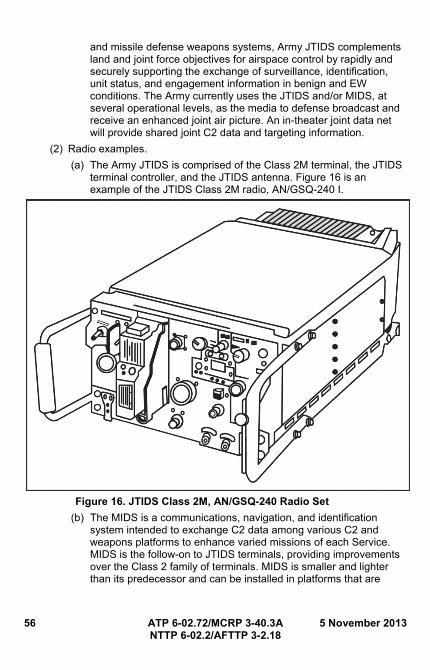
56 ATP 6-02.72/MCRP 3-40.3A 5 November 2013 NTTP 6-02.2/AFTTP 3-2.18
and missile defense weapons systems, Army JTIDS complements land and joint force objectives for airspace control by rapidly and securely supporting the exchange of surveillance, identification, unit status, and engagement information in benign and EW conditions. The Army currently uses the JTIDS and/or MIDS, at several operational levels, as the media to defense broadcast and receive an enhanced joint air picture. An in-theater joint data net will provide shared joint C2 data and targeting information.
(2) Radio examples.
(a) The Army JTIDS is comprised of the Class 2M terminal, the JTIDS terminal controller, and the JTIDS antenna. Figure 16 is an example of the JTIDS Class 2M radio, AN/GSQ-240 I.
Figure 16. JTIDS Class 2M, AN/GSQ-240 Radio Set
(b) The MIDS is a communications, navigation, and identification system intended to exchange C2 data among various C2 and weapons platforms to enhance varied missions of each Service. MIDS is the follow-on to JTIDS terminals, providing improvements over the Class 2 family of terminals. MIDS is smaller and lighter than its predecessor and can be installed in platforms that are
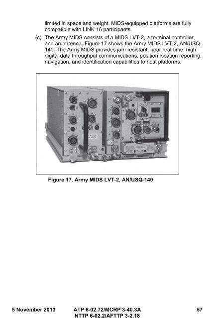
5 November 2013 ATP 6-02.72/MCRP 3-40.3A 57 NTTP 6-02.2/AFTTP 3-2.18
limited in space and weight. MIDS-equipped platforms are fully compatible with LINK 16 participants.
(c) The Army MIDS consists of a MIDS LVT-2, a terminal controller, and an antenna. Figure 17 shows the Army MIDS LVT-2, AN/USQ-140. The Army MIDS provides jam-resistant, near real-time, high digital data throughput communications, position location reporting, navigation, and identification capabilities to host platforms.
Figure 17. Army MIDS LVT-2, AN/USQ-140

58 ATP 6-02.72/MCRP 3-40.3A 5 November 2013 NTTP 6-02.2/AFTTP 3-2.18
This page intentionally left blank.
5 November 2013 ATP 6-02.72/MCRP 3-40.3A 59 NTTP 6-02.2/AFTTP 3-2.18
Chapter V MULTIBAND HIGH FREQUENCY, VERY HIGH FREQUENCY,
AND ULTRAHIGH FREQUENCY RADIOS
1. Overview
Multiband radios provide enhanced capabilities to air, land, and sea forces enabling users the capability to conduct SINCGARS and tactical satellite (TACSAT) communications. The multimode nature and versatility of multiband radios provides users with LOS and BLOS capabilities, ground-to-air, and ship-to-shore communications.
2. Multiband Radio Example
a. The multiband inter/intra team radio (MBITR) is used for company-sized nets depending on command guidance and mission requirements. Also, it can be used as a hand-held radio to support the secure communications of a platoon, squad, or team in a tactical environment. It enables small-unit leaders to adequately control the activities of subordinate elements. The MBITR can perform functions such as ground to air, ship to shore, civil to military, and multinational communications. The joint tactical radio system (JTRS) Enhanced MBITR also can operate in SATCOM mode. (MBITR versions 1 and 2 are not authorized to operate in SATCOM mode.) The MBITR radio set communicates with similar AM and FM radios to perform two-way communication. System management of the MBITR is the responsibility of the communications section at all echelons. A Windows-based personal computer radio program is provided to manage a large quantity of radios. The AN/VRC-111 is a vehicular mount, amplifier for the MBITR.
b. For conditions such as a small tactical unit’s area coverage, distance extension, urban operations, communications inside buildings or over urban terrain, the MBITR system provides a “back-to-back” (two radios) wireless network extension capability for COMSEC and PT modes. Other than two radios, the only hardware required for wireless network extension is a small cable kit and some electronic filters. When configured for wireless network extension operations, a true digital repeater is formed. Since the digits transmitted are merely being repeated by the radios, they do not degrade signal quality and the radios do not need COMSEC keys loaded in them.
c. The AN/PRC-148 and the AN/PRC-152 are COTS VHF LOS radios (multiband/multimode). One of the features of multiband/multimode radios that appeals to units is that all the multiband/multimode radios have SINCGARS and TACSAT capabilities.
d. The AN/PRC-148 was built for frequency and waveform interoperability with legacy and newer JTRS. The concept for JTRS was to ensure interoperability with virtually any common US military or commercial waveform operating in the 30–512 MHz frequency range with either FM or
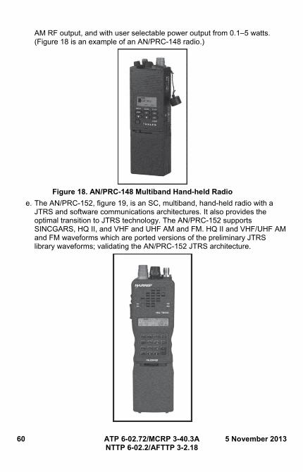
60 ATP 6-02.72/MCRP 3-40.3A 5 November 2013 NTTP 6-02.2/AFTTP 3-2.18
AM RF output, and with user selectable power output from 0.1–5 watts. (Figure 18 is an example of an AN/PRC-148 radio.)
Figure 18. AN/PRC-148 Multiband Hand-held Radio
e. The AN/PRC-152, figure 19, is an SC, multiband, hand-held radio with a JTRS and software communications architectures. It also provides the optimal transition to JTRS technology. The AN/PRC-152 supports SINCGARS, HQ II, and VHF and UHF AM and FM. HQ II and VHF/UHF AM and FM waveforms which are ported versions of the preliminary JTRS library waveforms; validating the AN/PRC-152 JTRS architecture.
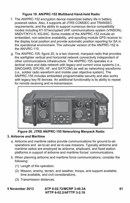
5 November 2013 ATP 6-02.72/MCRP 3-40.3A 61 NTTP 6-02.2/AFTTP 3-2.18
Figure 19. AN/PRC-152 Multiband Hand-held Radio
f. The AN/PRC-152 encryption device maximizes battery life in battery powered radios. Also, it supports all JTRS COMSEC and TRANSEC requirements, and the ability to support numerous device compatibility modes including KY-57/encrypted UHF communications system (VINSON), ANDVT/KYV-5, KG-84C. Some models of the AN/PRC-152 include an embedded, non-selective availability, anti-spoofing module GPS receiver to the display local position and provide automatic position reporting for SA in the operational environment. The vehicular version of the AN/PRC-152 is the AN/VRC-110.
g. The AN/PRC-155, figure 20, is a two channel, manpack radio that provides the warfighter vertical and horizontal network connectivity independent of other communications infrastructure. The AN/PRC-155 operates in a tactical voice and data network with legacy and current voice systems (i.e., SINCGARS, EPLRS, HF, and SATCOM) as well as networking waveforms (i.e., soldier radio waveform and mobile user objective system). The AN/PRC-155 includes embedded programmable security and also works with legacy key fill devices. An additional functionality is its ability to repeat for remote receiving and re-transmission.
Figure 20. JTRS AN/PRC-155 Networking Manpack Radio
3. Airborne and Maritime
a. Airborne and maritime radios provide communications for ground-to-air operations and air-to-air and air-to-sea missions. Typically airborne and maritime radios are employed as airborne, shipboard, and fixed-station platforms in support of airborne and maritime forces’ communications.
b. When planning airborne and maritime force communications, consider the following:
(1) Length of the operation.
(2) Mission, enemy, terrain, and weather, troops, and support available, time available, and civil considerations.
(3) Transmission distances.
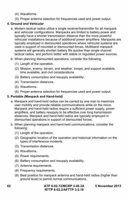
62 ATP 6-02.72/MCRP 3-40.3A 5 November 2013 NTTP 6-02.2/AFTTP 3-2.18
(4) Waveforms.
(5) Proper antenna selection for frequencies used and power output.
4. Ground and Vehicular
a. Modern tactical radios utilize a single receiver/transmitter for all manpack and vehicular configurations. Manpacks are limited to battery power and typically have a shorter transmission distance than the more powerful vehicular installations because of additional power amplifiers. Manpacks are typically employed in dismounted operations where vehicular systems are used in support of mounted or dismounted forces. Multiband manpack systems will generally shorten battery life quicker than single channel tactical radios, and perform better with stable or regulated power sources.
b. When planning dismounted operations, consider the following:
(1) Length of the operation.
(2) Mission, enemy, terrain, and weather, troops, and support available, time available, and civil considerations
(3) Battery consumption and resupply availability.
(4) Transmission distances.
(5) Waveforms.
(6) Proper antenna selection for frequencies used and power output.
5. Portable (Manpack and Hand-held)
a. Manpack and hand-held radios can be carried by one man to maximize user mobility and provide reliable communications while on the move. Manpack and hand-held radios require a sufficient power supply, power amplifiers, and battery resupply to be effective over long transmission distances. Manpack and hand-held radios are typically employed in dismounted operations in support of dismounted forces.
b. When planning manpack and hand-held communications, consider the following:
(1) Length of the operation.
(2) Geographic location of the operation and historical information on the types of interference incidents.
(3) Transmission distances.
(4) Waveforms.
(5) Power requirements.
(6) Battery consumption and resupply availability.
(7) Antenna requirements.
(8) Frequency requirements.
(9) Best position for manpack antenna and hand-held radios (higher than ground level) to permit normal communications.
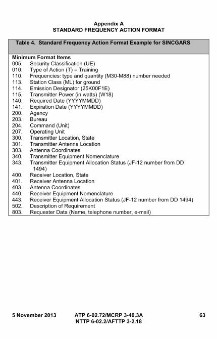
5 November 2013 ATP 6-02.72/MCRP 3-40.3A 63 NTTP 6-02.2/AFTTP 3-2.18
Appendix A STANDARD FREQUENCY ACTION FORMAT
Table 4. Standard Frequency Action Format Example for SINCGARS
Minimum Format Items 005. Security Classification (UE) 010. Type of Action (T) = Training 110. Frequencies: type and quantity (M30-M88) number needed 113. Station Class (ML) for ground 114. Emission Designator (25K00F1E) 115. Transmitter Power (in watts) (W18) 140. Required Date (YYYYMMDD) 141. Expiration Date (YYYYMMDD) 200. Agency 203. Bureau 204. Command (Unit) 207. Operating Unit 300. Transmitter Location, State 301. Transmitter Antenna Location 303. Antenna Coordinates 340. Transmitter Equipment Nomenclature 343. Transmitter Equipment Allocation Status (JF-12 number from DD 1494) 400. Receiver Location, State 401. Receiver Antenna Location 403. Antenna Coordinates 440. Receiver Equipment Nomenclature 443. Receiver Equipment Allocation Status (JF-12 number from DD 1494) 502. Description of Requirement 803. Requester Data (Name, telephone number, e-mail)
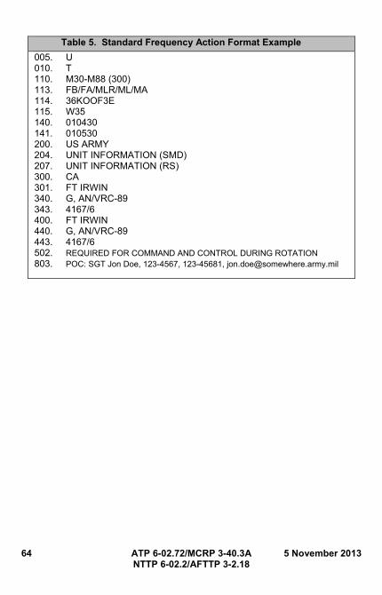
64 ATP 6-02.72/MCRP 3-40.3A 5 November 2013 NTTP 6-02.2/AFTTP 3-2.18
Table 5. Standard Frequency Action Format Example
005. U 010. T 110. M30-M88 (300) 113. FB/FA/MLR/ML/MA 114. 36KOOF3E 115. W35 140. 010430 141. 010530 200. US ARMY 204. UNIT INFORMATION (SMD) 207. UNIT INFORMATION (RS) 300. CA 301. FT IRWIN 340. G, AN/VRC-89 343. 4167/6 400. FT IRWIN 440. G, AN/VRC-89 443. 4167/6 502. REQUIRED FOR COMMAND AND CONTROL DURING ROTATION 803. POC: SGT Jon Doe, 123-4567, 123-45681, [email protected]
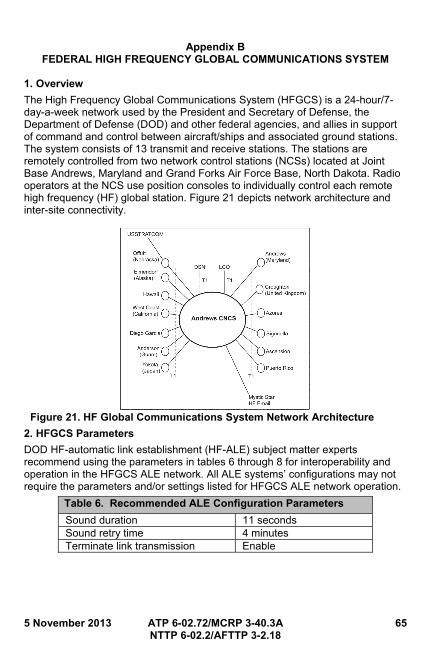
5 November 2013 ATP 6-02.72/MCRP 3-40.3A 65 NTTP 6-02.2/AFTTP 3-2.18
Appendix B FEDERAL HIGH FREQUENCY GLOBAL COMMUNICATIONS SYSTEM
1. Overview
The High Frequency Global Communications System (HFGCS) is a 24-hour/7-day-a-week network used by the President and Secretary of Defense, the Department of Defense (DOD) and other federal agencies, and allies in support of command and control between aircraft/ships and associated ground stations. The system consists of 13 transmit and receive stations. The stations are remotely controlled from two network control stations (NCSs) located at Joint Base Andrews, Maryland and Grand Forks Air Force Base, North Dakota. Radio operators at the NCS use position consoles to individually control each remote high frequency (HF) global station. Figure 21 depicts network architecture and inter-site connectivity.
Figure 21. HF Global Communications System Network Architecture
2. HFGCS Parameters
DOD HF-automatic link establishment (HF-ALE) subject matter experts recommend using the parameters in tables 6 through 8 for interoperability and operation in the HFGCS ALE network. All ALE systems’ configurations may not require the parameters and/or settings listed for HFGCS ALE network operation.
Table 6. Recommended ALE Configuration Parameters
Sound duration 11 seconds Sound retry time 4 minutes Terminate link transmission Enable
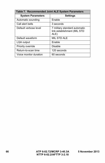
66 ATP 6-02.72/MCRP 3-40.3A 5 November 2013 NTTP 6-02.2/AFTTP 3-2.18
Table 7. Recommended Joint ALE System Parameters
System Parameters Settings
Automatic sounding Enable
Call alert bells 3 seconds
Default verbose level 7 military standard automatic link establishment (MIL STD ALE)
Default waveform MIL STD ALE
LQA output Enable
Priority override Disable
Return-to-scan time 120 seconds
Voice monitor duration 60 seconds
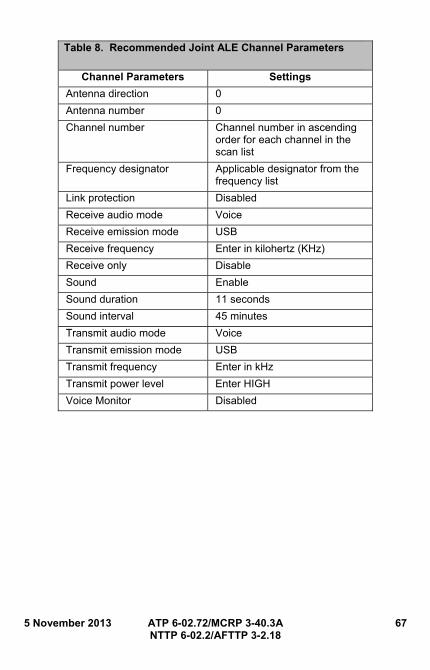
5 November 2013 ATP 6-02.72/MCRP 3-40.3A 67 NTTP 6-02.2/AFTTP 3-2.18
Table 8. Recommended Joint ALE Channel Parameters
Channel Parameters Settings
Antenna direction 0
Antenna number 0
Channel number Channel number in ascending order for each channel in the scan list
Frequency designator Applicable designator from the frequency list
Link protection Disabled
Receive audio mode Voice
Receive emission mode USB
Receive frequency Enter in kilohertz (KHz)
Receive only Disable
Sound Enable
Sound duration 11 seconds
Sound interval 45 minutes
Transmit audio mode Voice
Transmit emission mode USB
Transmit frequency Enter in kHz
Transmit power level Enter HIGH
Voice Monitor Disabled

68 ATP 6-02.72/MCRP 3-40.3A 5 November 2013 NTTP 6-02.2/AFTTP 3-2.18
This page intentionally left blank.
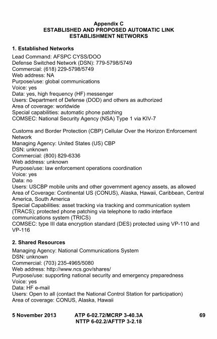
5 November 2013 ATP 6-02.72/MCRP 3-40.3A 69 NTTP 6-02.2/AFTTP 3-2.18
Appendix C ESTABLISHED AND PROPOSED AUTOMATIC LINK
ESTABLISHMENT NETWORKS 1. Established Networks
Lead Command: AFSPC CYSS/DOO Defense Switched Network (DSN): 779-5798/5749 Commercial: (618) 229-5798/5749 Web address: NA Purpose/use: global communications Voice: yes Data: yes, high frequency (HF) messenger Users: Department of Defense (DOD) and others as authorized Area of coverage: worldwide Special capabilities: automatic phone patching COMSEC: National Security Agency (NSA) Type 1 via KIV-7 Customs and Border Protection (CBP) Cellular Over the Horizon Enforcement Network Managing Agency: United States (US) CBP DSN: unknown Commercial: (800) 829-6336 Web address: unknown Purpose/use: law enforcement operations coordination Voice: yes Data: no Users: USCBP mobile units and other government agency assets, as allowed Area of Coverage: Continental US (CONUS), Alaska, Hawaii, Caribbean, Central America, South America Special Capabilities: asset tracking via tracking and communication system (TRACS); protected phone patching via telephone to radio interface communications system (TRICS) COMSEC: type III data encryption standard (DES) protected using VP-110 and VP-116 2. Shared Resources
Managing Agency: National Communications System DSN: unknown Commercial: (703) 235-4965/5080 Web address: http://www.ncs.gov/shares/ Purpose/use: supporting national security and emergency preparedness Voice: yes Data: HF e-mail Users: Open to all (contact the National Control Station for participation) Area of coverage: CONUS, Alaska, Hawaii
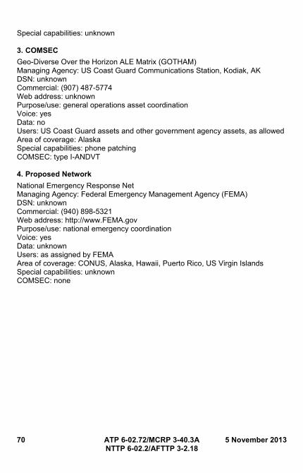
70 ATP 6-02.72/MCRP 3-40.3A 5 November 2013 NTTP 6-02.2/AFTTP 3-2.18
Special capabilities: unknown 3. COMSEC
Geo-Diverse Over the Horizon ALE Matrix (GOTHAM) Managing Agency: US Coast Guard Communications Station, Kodiak, AK DSN: unknown Commercial: (907) 487-5774 Web address: unknown Purpose/use: general operations asset coordination Voice: yes Data: no Users: US Coast Guard assets and other government agency assets, as allowed Area of coverage: Alaska Special capabilities: phone patching COMSEC: type I-ANDVT 4. Proposed Network
National Emergency Response Net Managing Agency: Federal Emergency Management Agency (FEMA) DSN: unknown Commercial: (940) 898-5321 Web address: http://www.FEMA.gov Purpose/use: national emergency coordination Voice: yes Data: unknown Users: as assigned by FEMA Area of coverage: CONUS, Alaska, Hawaii, Puerto Rico, US Virgin Islands Special capabilities: unknown COMSEC: none
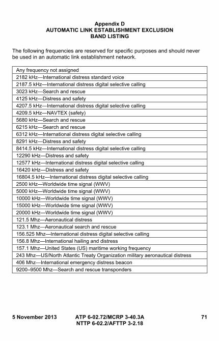
5 November 2013 ATP 6-02.72/MCRP 3-40.3A 71 NTTP 6-02.2/AFTTP 3-2.18
Appendix D AUTOMATIC LINK ESTABLISHMENT EXCLUSION
BAND LISTING
The following frequencies are reserved for specific purposes and should never be used in an automatic link establishment network.
Any frequency not assigned
2182 kHz—International distress standard voice
2187.5 kHz—International distress digital selective calling
3023 kHz—Search and rescue
4125 kHz—Distress and safety
4207.5 kHz—International distress digital selective calling
4209.5 kHz—NAVTEX (safety)
5680 kHz—Search and rescue
6215 kHz—Search and rescue
6312 kHz—International distress digital selective calling
8291 kHz—Distress and safety
8414.5 kHz—International distress digital selective calling
12290 kHz—Distress and safety
12577 kHz—International distress digital selective calling
16420 kHz—Distress and safety
16804.5 kHz—International distress digital selective calling
2500 kHz—Worldwide time signal (WWV)
5000 kHz—Worldwide time signal (WWV)
10000 kHz—Worldwide time signal (WWV)
15000 kHz—Worldwide time signal (WWV)
20000 kHz—Worldwide time signal (WWV)
121.5 Mhz—Aeronautical distress
123.1 Mhz—Aeronautical search and rescue
156.525 Mhz—International distress digital selective calling
156.8 Mhz—International hailing and distress
157.1 Mhz—United States (US) maritime working frequency
243 Mhz—US/North Atlantic Treaty Organization military aeronautical distress
406 Mhz—International emergency distress beacon
9200–9500 Mhz—Search and rescue transponders

72 ATP 6-02.72/MCRP 3-40.3A 5 November 2013 NTTP 6-02.2/AFTTP 3-2.18
This page intentionally left blank.
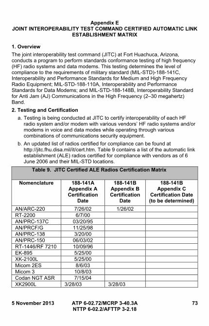
5 November 2013 ATP 6-02.72/MCRP 3-40.3A 73 NTTP 6-02.2/AFTTP 3-2.18
Appendix E JOINT INTEROPERABILITY TEST COMMAND CERTIFIED AUTOMATIC LINK
ESTABLISHMENT MATRIX 1. Overview
The joint interoperability test command (JITC) at Fort Huachuca, Arizona, conducts a program to perform standards conformance testing of high frequency (HF) radio systems and data modems. This testing determines the level of compliance to the requirements of military standard (MIL-STD)-188-141C, Interoperability and Performance Standards for Medium and High Frequency Radio Equipment; MIL-STD-188-110A, Interoperability and Performance Standards for Data Modems; and MIL-STD-188-148B, Interoperability Standard for Anti Jam (AJ) Communications in the High Frequency (2–30 megahertz) Band.
2. Testing and Certification
a. Testing is being conducted at JITC to certify interoperability of each HF radio system and/or modem with various vendors’ HF radio systems and/or modems in voice and data modes while operating through various combinations of communications security equipment.
b. An updated list of radios certified for compliance can be found at http://jitc.fhu.disa.mil/it/cert.htm. Table 9 contains a list of the automatic link establishment (ALE) radios certified for compliance with vendors as of 6 June 2006 and their MIL-STD locations.
Table 9. JITC Certified ALE Radios Certification Matrix
Nomenclature 188-141A Appendix A Certification
Date
188-141B Appendix B Certification
Date
188-141B Appendix C
Certification Date (to be determined)
AN/ARC-220 7/26/02 1/26/02 RT-2200 6/7/00 AN/PRC-137C 03/20/95 AN/PRCF/G 11/25/98 AN/PRC-138 3/20/00 AN/PRC-150 06/03/02 RT-1446/RF 7210 10/09/96 EK-895 5/25/00 XK-2100L 5/25/00 Micom 2ES 8/6/03 Micom 3 10/8/03 Codan NGT ASR 7/15/04 XK2900L 3/28/03 3/28/03

74 ATP 6-02.72/MCRP 3-40.3A 5 November 2013 NTTP 6-02.2/AFTTP 3-2.18
This page intentionally left blank.
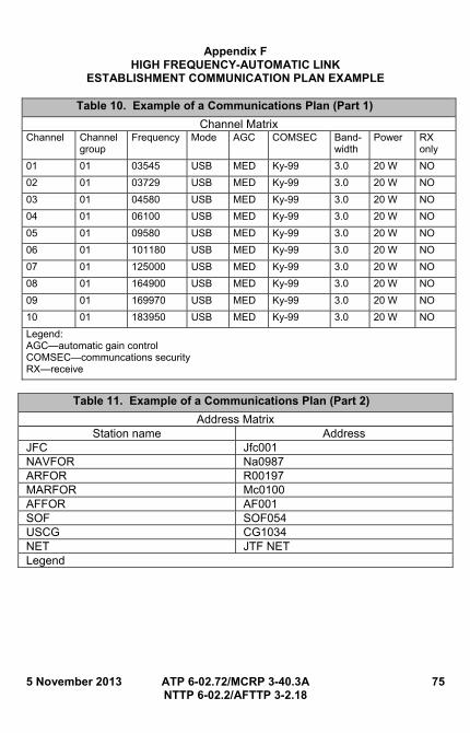
5 November 2013 ATP 6-02.72/MCRP 3-40.3A 75 NTTP 6-02.2/AFTTP 3-2.18
Appendix F HIGH FREQUENCY-AUTOMATIC LINK
ESTABLISHMENT COMMUNICATION PLAN EXAMPLE
Table 10. Example of a Communications Plan (Part 1)
Channel Matrix Channel Channel
group Frequency Mode AGC COMSEC Band-
width Power RX
only
01 01 03545 USB MED Ky-99 3.0 20 W NO
02 01 03729 USB MED Ky-99 3.0 20 W NO
03 01 04580 USB MED Ky-99 3.0 20 W NO
04 01 06100 USB MED Ky-99 3.0 20 W NO
05 01 09580 USB MED Ky-99 3.0 20 W NO
06 01 101180 USB MED Ky-99 3.0 20 W NO
07 01 125000 USB MED Ky-99 3.0 20 W NO
08 01 164900 USB MED Ky-99 3.0 20 W NO
09 01 169970 USB MED Ky-99 3.0 20 W NO
10 01 183950 USB MED Ky-99 3.0 20 W NO
Legend: AGC—automatic gain control COMSEC—communcations security RX—receive
Table 11. Example of a Communications Plan (Part 2)
Address Matrix Station name Address
JFC Jfc001 NAVFOR Na0987 ARFOR R00197 MARFOR Mc0100 AFFOR AF001 SOF SOF054 USCG CG1034 NET JTF NET Legend

76 ATP 6-02.72/MCRP 3-40.3A 5 November 2013 NTTP 6-02.2/AFTTP 3-2.18
This page intentionally left blank.
5 November 2013 ATP 6-02.72/MCRP 3-40.3A 77 NTTP 6-02.2/AFTTP 3-2.18
Appendix G HIGH FREQUENCY-AUTOMATIC LINK
ESTABLISHMENT RADIO PROGRAMMING APPLICATION EXAMPLE
1. Third Generation (3G) Utility Functions
a. To enter 3G mode, press the number 3 key or mode key on the keypad menu until 3G appears on the display, then press [ENT].
b. The utility and test functions in 3G mode are the same as in other modes with the exception of the 3G-specific utilities.
c. From the preset screen (top right), press [OPT] to display the Options Menu. Press [◄] or [►] until 3G is highlighted; then press [ENT].
2. The 3G, 3G+: Link Quality Analysis (LQA)
a. Press [◄] or [►] until LQA is highlighted; then press [ENT].
b. LQA may be EXCHANGE or SOUND, and function identically as under ALE mode. Select EXCHANGE or SOUND and press [ENT].
c. The radio must be in SYNC for LQA to function. Use the p and q arrows to select exchange destinations.
d. When LQA is completed, press [◄] or [►] until SCORES is highlighted; then press [ENT].
e. Select Individual Address and press [ENT].
3. The 3G, 3G+: Time of Day (TOD)
a. The receive/transmit (R/T) TOD can be manually set when synchronization from a TOD Server or Global Positioning System (GPS) is unavailable.
b. From the preset screen, press [OPT] to display the Options Menu. Press [◄] or [►] until 3G is highlighted; then press [ENT].
c. Press [◄] or [►] until TOD is highlighted; then press [ENT].
d. Enter the correct TOD in 24-hour format; then press [ENT].
e. Enter the correct date; then press [ENT].
f. Press [OPT] to return to the Preset screen.
4. The 3G, 3G+: TOD Role
a. The R/T TOD Role defines where TOD Sync will be derived and the role of this station.
b. From the preset screen, press [OPT] to display the Options Menu. Press [◄] or [►] until 3G is highlighted; then press [ENT].
c. Press [◄] or [►] until TODROLE is highlighted; then press [ENT].
d. Use [p] or [▼] to select the TOD Server station name; then press [ENT].
78 ATP 6-02.72/MCRP 3-40.3A 5 November 2013 NTTP 6-02.2/AFTTP 3-2.18
e. Use [p] or [▼] to select the TOD Role for this station; then press [ENT]. Choices are Base and Outstation.
f. Press [OPT] to return to the Preset screen
5. The 3G, 3G+: View List of Linked Radios
a. The LINKED menu displays the addresses of the other linked radios.
b. From the preset screen, press [OPT] to display the Options Menu. Press [◄] or [►] until 3G is highlighted; then press [ENT].
c. Press [◄] or [►] until LINKED is highlighted; then press [ENT].
d. Use p and q keys to scroll through the list of addresses of linked radios.
6. The 3G Operation
a. Press the [MODE] button to scroll through the available operating modes.
b. Choices are: FIX, ALE, HOP, 3G and 3G+.
c. Press [MODE] until 3G is displayed.
d. Press [ENT] to select 3G mode.
e. If AUTOTUNE was not selected during programming, the R/T will indicate the need for tuning. Press [OPT], select RETUNE; then press [ENT].
f. The radio will begin scanning when 3G mode is selected. The displayed channel number (CH) will change as the radio scans through the list of 3G channels.
g. Press [] to momentarily display the Channel screen.
(1) The display will return to the Preset screen after a few seconds.
(2) Press [CALL] to display the CALL TYPE menu. The choices are: MANUAL, AUTOMATIC, SYNC REQUEST, and BEST. Scroll to AUTOMATIC; then press [ENT].
h. The ADDRESS TYPE menu is then displayed. Select the desired ADDRESS TYPE; then press [ENT].
i. Scroll through the list of addresses to the desired address. Press [ENT].
j. The radio will begin transmitting a call to the selected address.
k. After the call has been transmitted, the radio will wait for a response.
l. When a response has been received, the Radio will indicate that it is LINKED.
m. Press [CLR] to return to the preset screen.
n. While linked, press [CLR] from the preset screen.
o. The radio will display the TERMINATE LINK? menu.
p. To terminate the link, scroll to YES; then press [ENT].
q. The radio will begin transmitting a link termination message.
5 November 2013 ATP 6-02.72/MCRP 3-40.3A 79 NTTP 6-02.2/AFTTP 3-2.18
7. Place an Automatic Link Establishment (ALE) Call in 3G+
a. An individual call is used to establish communications (connection) between two stations. An individual call may be placed to any programmed individual address.
b. Press [CALL] to display the CALL TYPE menu choices (3G MANUAL, 3G AUTOMATIC, 3G BEST, 3G BROADCAST SYNC, 3G BDCAST SYNC-ALL, 3G SEND GPS REPORT, ALE MANUAL, and ALE AUTOMATIC).
c. Use the p and q keys to scroll through the options. Select ALE AUTOMATIC; then press [ENT]. ALE AUTOMATIC allows the radio to attempt the call on all channels in the channel group according to LQA scores or from the highest to the lowest frequency, if no LQA score data exists.
d. If ALE MANUAL is selected, the channel to be used also will be operator selected. The ALE call will be attempted on this channel and if the called station is not reachable, the call ends.
e. The ADDRESS TYPE menu is then displayed. Using the p and q keys, select the desired address type (INDIVIDUAL, NET, ANY, ALL); then press [ENT].
f. Use the p and q keys to select the desired address; then press [ENT].
g. The R/T will begin transmitting to the selected address. After the call, the R/T will wait for the response.
h. When a response has been received, the R/T will indicate LINKED on the liquid crystal display (LCD). The radio will then make available the programmed system preset items programmed to the linked self address.
8. ALE: Program/Operation
a. Channel Group:
(1) Press [PGM] button.
(2) Press the [◄] or [►] arrow until MODE is highlighted.
(3) Press the [ENT] button.
(4) Press the [◄] or [►] arrow until ALE is highlighted.
(5) Press the [ENT] button.
(6) Press the [◄] or [►] arrow until CHAN_GROUP is highlighted.
(7) Press the [ENT] button.
(8) ADD is highlighted.
(9) Press the [ENT] button.
(10) Enter CH Group Number 002–49.
(11) Press the [ENT] button.
(12) ADD is highlighted.
80 ATP 6-02.72/MCRP 3-40.3A 5 November 2013 NTTP 6-02.2/AFTTP 3-2.18
Note: Operators should see PGM-MODE-ALE-CHAN_GROUP and the CH Group being altered is in the far right corner of the radio.
(13) Press the [ENT] button.
(14) Enter the channel preset numbers that each operator programmed earlier. (Example 01 [ENT], 02 [ENT], 03 [ENT], and 04 [ENT]).
(15) Press the [CLR] button.
(16) Press the [▲] or [▼] arrow until REVIEW is highlighted.
(17) Press the [ENT] button.
(18) Press the [▲] to view all previously entered channel presets. (Example: if four channel presets are entered press the [▲] arrow four times to view all channel presets).
(19) Press the [CLR] button three times.
(20) CHAN_GROUP is highlighted.
Note: Operators have now finished programming the Channel Group. Follow steps 6 through 18 to create additional channel groups.
b. Self Address: The following steps explain programming the ALE Self Address. Continuing from the CHAN_GROUP screen execute the steps that follow.
(1) Press the [◄] or [►] arrow until ADDRESS is highlighted.
(2) Press the [ENT] button.
(3) Press the [◄] or [►] arrow until SELF is highlighted.
(4) Press the [ENT] button.
(5) ADD is highlighted.
(6) Press the [ENT] button.
(7) Type in the desired one- to three-character self address (Example: RT1).
Note: Additional self addresses may be up to 15 characters long. Up to 20 self addresses can be programmed. By entering more than three characters, the operator will increase the signaling time on the radio.
(8) Press the [ENT] button.
(9) Enter desired CHANNEL GROUP 00–49.
(10) Press the [ENT] button.
(11) SELF is highlighted.
Note: Operators have completed programming of the self address. To enter an additional self address, follow steps 3 through 11.
c. Individual Address:
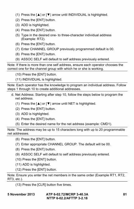
5 November 2013 ATP 6-02.72/MCRP 3-40.3A 81 NTTP 6-02.2/AFTTP 3-2.18
(1) Press the [▲] or [▼] arrow until INDIVIDUAL is highlighted.
(2) Press the [ENT] button.
(3) ADD is highlighted.
(4) Press the [ENT] button.
(5) Type in the desired one- to three-character individual address (Example: RT2).
(6) Press the [ENT] button.
(7) Enter CHANNEL GROUP previously programmed default is 00.
(8) Press the [ENT] button.
(9) ASSOC SELF will default to self address previously entered.
Note: If there is more than one self address, ensure each operator chooses the correct one for the channel group with which he or she is working.
(10) Press the [ENT] button.
(11) INDIVIDUAL is highlighted.
Note: Each operator has the knowledge to program an individual address. Follow steps 1 through 10 to create additional addresses.
d. Net Address: Starting after step 10, follow the steps below to program the net address.
(1) Press the [▲] or [▼] arrow until NET is highlighted.
(2) Press the [ENT] button.
(3) ADD is highlighted.
(4) Press the [ENT] button.
(5) Enter the desired name for the net address (example: CMD1).
Note: The address may be up to 15 characters long with up to 20 programmable net addresses.
(6) Press the [ENT] button.
(7) Enter appropriate CHANNEL GROUP. The default will be 00.
(8) Press the [ENT] button.
(9) ASSOC SELF will default to self address previously entered.
(10) Press the [ENT] button.
(11) ADD is highlighted.
(12) Press the [ENT] button.
Note: Ensure you enter the net members in the same order (Example RT1, RT2, RT3, etc.).
(13) Press the [CLR] button five times.
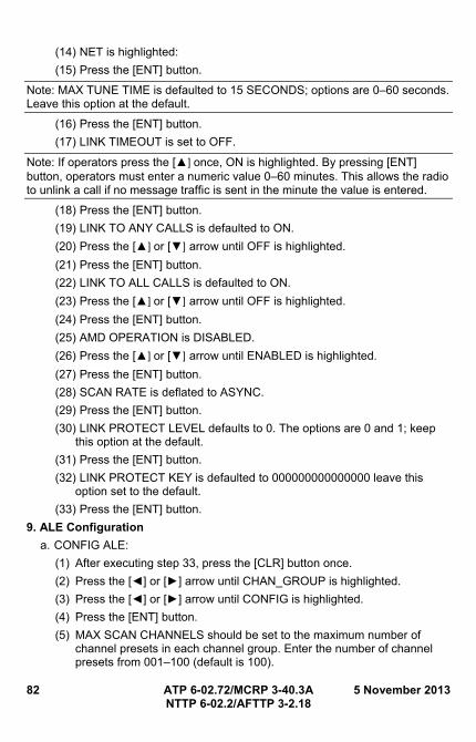
82 ATP 6-02.72/MCRP 3-40.3A 5 November 2013 NTTP 6-02.2/AFTTP 3-2.18
(14) NET is highlighted:
(15) Press the [ENT] button.
Note: MAX TUNE TIME is defaulted to 15 SECONDS; options are 0–60 seconds. Leave this option at the default.
(16) Press the [ENT] button.
(17) LINK TIMEOUT is set to OFF.
Note: If operators press the [▲] once, ON is highlighted. By pressing [ENT] button, operators must enter a numeric value 0–60 minutes. This allows the radio to unlink a call if no message traffic is sent in the minute the value is entered.
(18) Press the [ENT] button.
(19) LINK TO ANY CALLS is defaulted to ON.
(20) Press the [▲] or [▼] arrow until OFF is highlighted.
(21) Press the [ENT] button.
(22) LINK TO ALL CALLS is defaulted to ON.
(23) Press the [▲] or [▼] arrow until OFF is highlighted.
(24) Press the [ENT] button.
(25) AMD OPERATION is DISABLED.
(26) Press the [▲] or [▼] arrow until ENABLED is highlighted.
(27) Press the [ENT] button.
(28) SCAN RATE is deflated to ASYNC.
(29) Press the [ENT] button.
(30) LINK PROTECT LEVEL defaults to 0. The options are 0 and 1; keep this option at the default.
(31) Press the [ENT] button.
(32) LINK PROTECT KEY is defaulted to 000000000000000 leave this option set to the default.
(33) Press the [ENT] button.
9. ALE Configuration
a. CONFIG ALE:
(1) After executing step 33, press the [CLR] button once.
(2) Press the [◄] or [►] arrow until CHAN_GROUP is highlighted.
(3) Press the [◄] or [►] arrow until CONFIG is highlighted.
(4) Press the [ENT] button.
(5) MAX SCAN CHANNELS should be set to the maximum number of channel presets in each channel group. Enter the number of channel presets from 001–100 (default is 100).
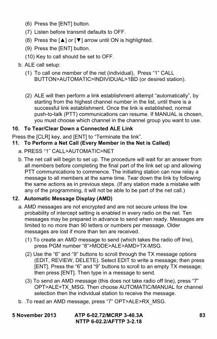
5 November 2013 ATP 6-02.72/MCRP 3-40.3A 83 NTTP 6-02.2/AFTTP 3-2.18
(6) Press the [ENT] button.
(7) Listen before transmit defaults to OFF.
(8) Press the [▲] or [▼] arrow until ON is highlighted.
(9) Press the [ENT] button.
(10) Key to call should be set to OFF.
b. ALE call setup:
(1) To call one member of the net (individual), Press “1” CALL BUTTON>AUTOMATIC>INDIVIDUAL>1BD (or desired station).
(2) ALE will then perform a link establishment attempt “automatically”, by starting from the highest channel number in the list, until there is a successful link establishment. Once the link is established, normal push-to-talk (PTT) communications can resume. If MANUAL is chosen, you must choose which channel in the channel group you want to use.
10. To Tear/Clear Down a Connected ALE Link
Press the [CLR] key, and [ENT] to “Terminate the link”. 11. To Perform a Net Call (Every Member in the Net is Called)
a. PRESS “1” CALL>AUTOMATIC>NET
b. The net call will begin to set up. The procedure will wait for an answer from all members before completing the final part of the link set up and allowing PTT communications to commence. The initiating station can now relay a message to all members at the same time. Tear down the link by following the same actions as in previous steps. (If any station made a mistake with any of the programming, it will not be able to be part of the net call.)
12. Automatic Message Display (AMD)
a. AMD messages are not encrypted and are not secure unless the low probability of intercept setting is enabled in every radio on the net. Ten messages may be prepared in advance to send when ready. Messages are limited to no more than 90 letters or numbers per message. Older messages are lost if more than ten are received.
(1) To create an AMD message to send (which takes the radio off line), press PGM number “8”>MODE>ALE>AMD>TX-MSG.
(2) Use the “6” and “9” buttons to scroll through the TX message options (EDIT, REVIEW, DELETE). Select EDIT to write a message; then press [ENT]. Press the “6” and “9” buttons to scroll to an empty TX message; then press [ENT]. Then type in a message to send.
(3) To send an AMD message (this does not take radio off line), press “7” OPT>ALE>TX_MSG. Then choose AUTOMATIC/MANUAL for channel selection then the individual station to receive the message.
b. .To read an AMD message, press “7” OPT>ALE>RX_MSG.
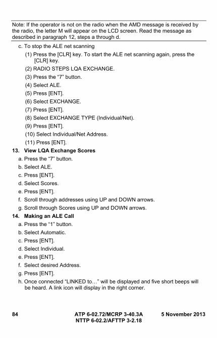
84 ATP 6-02.72/MCRP 3-40.3A 5 November 2013 NTTP 6-02.2/AFTTP 3-2.18
Note: If the operator is not on the radio when the AMD message is received by the radio, the letter M will appear on the LCD screen. Read the message as described in paragraph 12, steps a through d.
c. To stop the ALE net scanning
(1) Press the [CLR] key. To start the ALE net scanning again, press the [CLR] key.
(2) RADIO STEPS LQA EXCHANGE.
(3) Press the “7” button.
(4) Select ALE.
(5) Press [ENT].
(6) Select EXCHANGE.
(7) Press [ENT].
(8) Select EXCHANGE TYPE (Individual/Net).
(9) Press [ENT].
(10) Select Individual/Net Address.
(11) Press [ENT].
13. View LQA Exchange Scores
a. Press the “7” button.
b. Select ALE.
c. Press [ENT].
d. Select Scores.
e. Press [ENT].
f. Scroll through addresses using UP and DOWN arrows.
g. Scroll through Scores using UP and DOWN arrows.
14. Making an ALE Call
a. Press the “1” button.
b. Select Automatic.
c. Press [ENT].
d. Select Individual.
e. Press [ENT].
f. Select desired Address.
g. Press [ENT].
h. Once connected “LINKED to…” will be displayed and five short beeps will be heard. A link icon will display in the right corner.
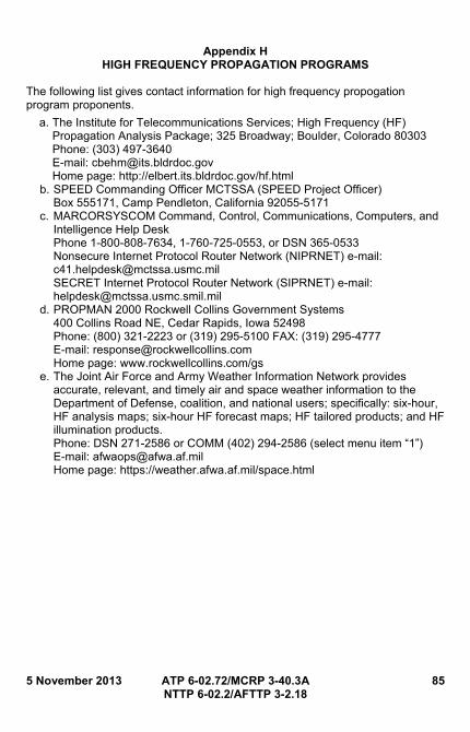
5 November 2013 ATP 6-02.72/MCRP 3-40.3A 85 NTTP 6-02.2/AFTTP 3-2.18
Appendix H HIGH FREQUENCY PROPAGATION PROGRAMS
The following list gives contact information for high frequency propogation program proponents.
a. The Institute for Telecommunications Services; High Frequency (HF) Propagation Analysis Package; 325 Broadway; Boulder, Colorado 80303 Phone: (303) 497-3640 E-mail: [email protected] Home page: http://elbert.its.bldrdoc.gov/hf.html
b. SPEED Commanding Officer MCTSSA (SPEED Project Officer) Box 555171, Camp Pendleton, California 92055-5171
c. MARCORSYSCOM Command, Control, Communications, Computers, and Intelligence Help Desk Phone 1-800-808-7634, 1-760-725-0553, or DSN 365-0533 Nonsecure Internet Protocol Router Network (NIPRNET) e-mail: [email protected] SECRET Internet Protocol Router Network (SIPRNET) e-mail: [email protected]
d. PROPMAN 2000 Rockwell Collins Government Systems 400 Collins Road NE, Cedar Rapids, Iowa 52498 Phone: (800) 321-2223 or (319) 295-5100 FAX: (319) 295-4777 E-mail: [email protected] Home page: www.rockwellcollins.com/gs
e. The Joint Air Force and Army Weather Information Network provides accurate, relevant, and timely air and space weather information to the Department of Defense, coalition, and national users; specifically: six-hour, HF analysis maps; six-hour HF forecast maps; HF tailored products; and HF illumination products. Phone: DSN 271-2586 or COMM (402) 294-2586 (select menu item “1”) E-mail: [email protected] Home page: https://weather.afwa.af.mil/space.html

86 ATP 6-02.72/MCRP 3-40.3A 5 November 2013 NTTP 6-02.2/AFTTP 3-2.18
This page intentionally left blank.
5 November 2013 ATP 6-02.72/MCRP 3-40.3A 87 NTTP 6-02.2/AFTTP 3-2.18
Appendix I SINGLE-CHANNEL GROUND AND AIRBORNE RADIO SYSTEM NETWORK
MANAGEMENT
1. Frequency Hopping (FH) Net Operations
The joint task force (JTF) director of command, control, communications, and computer systems of a joint staff has overall responsibility for ensuring interoperability of single-channel ground and airborne radio system (SINCGARS) nets. All Services currently have and deploy, SINCGARS and/or SINCGARS-FH radios. Forces assigned to a JTF will follow the SINCGARS procedures provided below.
a. Mode. SINCGARS radios can store FH data for unique FH nets. SINCGARS radios require four data elements to communicate in the FH mode. The data elements are: hopsets/lockouts; net identification (ID); net sync time; and a transmission security key (TSK). In addition, users in nets sharing a common hopset, TSK, and sync time can also move from net to net by entering the appropriate net ID. The term “channel” has come to represent the specific TSK used for a net. While not accurate, it is a widely used. Many software defined radios handle TSKs in very different fashions. Special care should be given when using unfamiliar radios on a SINCGARS net.
b. Net IDs. The net ID is a three-digit number from 000 to 999 used to distinguish one FH net from another when all other FH data elements are the same. Unique net IDs may be stored in each FH preset channel. Net IDs, embedded in the hopset data, are loaded electronically with a fill device or by electronic remote fill (ERF) and may be changed using the keypad or control panel of the SINCGARS remote terminal.
c. Sync time. Sync time is required for synchronization of the frequency hops. Sync time consists of the last two digits of the Julian date (SINCGARS Julian Date) plus a six-digit time (hours:minutes:seconds). Each station in the FH radio net must be within plus or minus four seconds of the net sync time to communicate. TSKs are electronically loaded into the radio with a fill device. After net opening, the TSK may be transferred by ERF.
2. Net Opening
a. Net control station (NCS). The NCS can open FH nets using hot or cold start net opening procedures. The preferred method is to open the net using hot start procedures. Before opening a net, the NCS must receive FH and communications security (COMSEC) data.
(1) Hot start net opening. Each member in the net loads all FH and COMSEC data into the radio, including sync time. The operator enters the net by contacting the NCS.
(2) Cold start net opening. Net stations receive their ERF from their NCS on the manual channel in the FH cipher text (CT) modes, store it in the
88 ATP 6-02.72/MCRP 3-40.3A 5 November 2013 NTTP 6-02.2/AFTTP 3-2.18
appropriate channel, switch over to that channel, and enter the net. Operators load all FH and COMSEC data, except sync time, into the radio prior to cold start net opening.
b. FH sync time management. The NCS should transmit periodically in FH-Master mode to eliminate the effects of time of day drift. A net member can obtain FH sync time from one of three methods. The model/version of SINCGARS radio and the available time sources (e.g., defense advanced global positioning system (GPS) receiver), determine the method for loading time. Methods include:
(1) ERF (net opening and update).
(2) Electronic fill.
(3) Entering time manually. Time can be entered manually by obtaining a GPS time hack through the SINCGARS radio front panel keypad.
3. Late Net Entry
Enabling passive late net entry. The SINCGARS radio has a built-in capability to resynchronize itself when out of synchronization by more than plus or minus four seconds, but less than plus or minus 60 seconds. When the operator enables the late net entry mode, the radio is brought back into the net without further action by the operator. A radio loaded with all FH and COMSEC data that drifts off sync time may be re-synchronized by one of three methods:
a. Entering GPS Zulu time.
b. Enabling passive late net entry. The SINCGARS radio has a built-in capability to resynchronize itself when out of synchronization by more than plus or minus four seconds, but less than plus or minus 60 seconds.
c. Activating CUE and ERF. If a SINCGARS station must enter an FH CT net and has the correct TSK and transmission encryption key, the station may contact the net by changing to the CUE frequency, pressing push-to-talk and waiting for the NCS to respond. This action by the operator causes the message CUE indicator to appear in the display of the NCS radio. Normally only selected NCSs, their alternate NCSs, or other designated stations, will load, monitor, and respond on the CUE frequency.
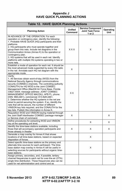
5 November 2013 ATP 6-02.72/MCRP 3-40.3A 89 NTTP 6-02.2/AFTTP 3-2.18
Appendix J HAVE QUICK PLANNING ACTIONS
Table 12. HAVE QUICK Planning Actions
Planning Action Unified
Command
Service Component Joint Task Force
1 or 2
Operating Unit
IN ADVANCE OF THE OPERATION: For each operation or contingency plan, identify the following: 1. Probable HAVE QUICK (HQ) participants and their platforms. 2. HQ participants who must operate together and group them into nets. Include net diagrams in the Communication Annex (Annex K) to the operation or contingency plan. 3. HQ systems that will be used in each net. Identify platforms with multiple HQ systems operating in two or more nets.
X X X X X
Establish a mode of operation for each net. It should be the most advanced mode supported by every HQ radio in the net. Annotate each HQ net diagram with the appropriate mode.
X
Verify: 1. All Services obtain word-of-day (WOD) from the National Security Agency through communications security (COMSEC) channels. The controlling authority CONAUTH) for HQ WOD is the Joint COMSEC Management Office (MacDill Air Force Base, Florida 33621-5504; message address: JOINT COMSEC MANAGEMENT OFFICE MACDILL AFB FL; phone: DSN: 968-2461), commercial: 813-828-2461. 2. Determine whether the HQ systems in the net are wired to permit securing the system. If so, identify the nets that will be secure, the number of different VINSON key lists required, and the CONAUTH for the key lists. Publish this information in Annex K.
X X
Requisition WOD and VINSON keying material through the Joint Staff Intertheater COMSEC package manager or Service chain of command.
X X
Define procedures for extracting WOD and VINSON key at the operating unit level.
X X
Identify the time-base stations available, including those that will accompany operation participants and those already in theater.
X X X
Generate a map overlay for Annex K that shows locations of all time-base stations, based on expected disposition of forces.
X
Select specific time-base stations as the primary and alternate time sources for each participant. The time-base station map overlay in Annex K will be useful in selecting sources for participants without organic time-base stations.
X
Assign primary, secondary, and, if possible, tertiary channel frequencies to each net for over-the-air (OTA) single time distribution. These frequencies also can be used for net administration and control and as
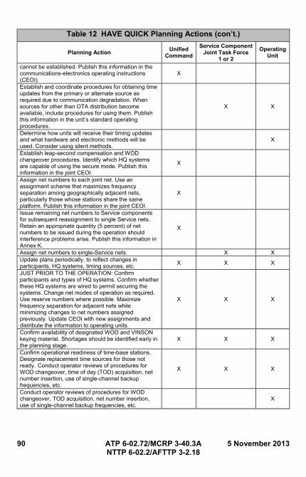
90 ATP 6-02.72/MCRP 3-40.3A 5 November 2013 NTTP 6-02.2/AFTTP 3-2.18
Table 12 HAVE QUICK Planning Actions (con’t.)
Planning Action Unified
Command
Service Component Joint Task Force
1 or 2
Operating Unit
cannot be established. Publish this information in the communications-electronics operating instructions (CEOI).
X
Establish and coordinate procedures for obtaining time updates from the primary or alternate source as required due to communication degradation. When sources for other than OTA distribution become available, include procedures for using them. Publish this information in the unit’s standard operating procedures.
X X
Determine how units will receive their timing updates and what hardware and electronic methods will be used. Consider using silent methods.
X
Establish leap-second compensation and WOD changeover procedures. Identify which HQ systems are capable of using the secure mode. Publish this information in the joint CEOI.
X
Assign net numbers to each joint net. Use an assignment scheme that maximizes frequency separation among geographically adjacent nets, particularly those whose stations share the same platform. Publish this information in the joint CEOI.
X
Issue remaining net numbers to Service components for subsequent reassignment to single Service nets. Retain an appropriate quantity (5 percent) of net numbers to be issued during the operation should interference problems arise. Publish this information in Annex K.
X
Assign net numbers to single-Service nets. X X Update plans periodically, to reflect changes in participants, HQ systems, timing sources, etc.
X X X
JUST PRIOR TO THE OPERATION: Confirm participants and types of HQ systems. Confirm whether these HQ systems are wired to permit securing the systems. Change net modes of operation as required. Use reserve numbers where possible. Maximize frequency separation for adjacent nets while minimizing changes to net numbers assigned previously. Update CEOI with new assignments and distribute the information to operating units.
X X X
Confirm availability of designated WOD and VINSON keying material. Shortages should be identified early in the planning stage.
X X X
Confirm operational readiness of time-base stations. Designate replacement time sources for those not ready. Conduct operator reviews of procedures for WOD changeover, time of day (TOD) acquisition, net number insertion, use of single-channel backup frequencies, etc.
X X X
Conduct operator reviews of procedures for WOD changeover, TOD acquisition, net number insertion, use of single-channel backup frequencies, etc.
X
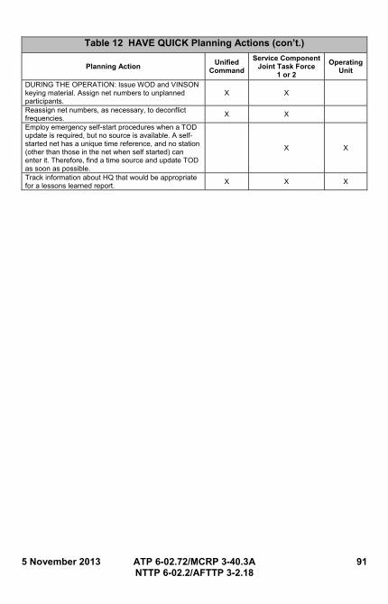
5 November 2013 ATP 6-02.72/MCRP 3-40.3A 91 NTTP 6-02.2/AFTTP 3-2.18
Table 12 HAVE QUICK Planning Actions (con’t.)
Planning Action Unified
Command
Service Component Joint Task Force
1 or 2
Operating Unit
DURING THE OPERATION: Issue WOD and VINSON keying material. Assign net numbers to unplanned participants.
X X
Reassign net numbers, as necessary, to deconflict frequencies.
X X
Employ emergency self-start procedures when a TOD update is required, but no source is available. A self-started net has a unique time reference, and no station (other than those in the net when self started) can enter it. Therefore, find a time source and update TOD as soon as possible.
X X
Track information about HQ that would be appropriate for a lessons learned report.
X X X

92 ATP 6-02.72/MCRP 3-40.3A 5 November 2013 NTTP 6-02.2/AFTTP 3-2.18
This page intentionally left blank.
5 November 2013 ATP 6-02.72/MCRP 3-40.3A 93 NTTP 6-02.2/AFTTP 3-2.18
Appendix K HAVE QUICK NET MANAGEMENT REQUIREMENTS
1. General
a. Net number, word-of-day (WOD), and time of day (TOD) settings separate users into distinct nets.
b. Net number prefixes are always "A.”
c. Net numbers are in the form XX.XYY (prefixed by “A” or “B") where Xs range from 0 to 9 and YY is chosen from the set (00, 25, 50, or 75).
2. Basic HQ I Nets
a. Net Types. The four types of active mode operations available in Basic HAVE QUICK (HQ) are: (1) A-nets.
(2) Sectionalized A-nets.
(3) B-nets.
(4) T-nets.
Note: Only T-nets are discussed in the following subparagraphs. A-nets, sectionalized A-nets, and B-nets are discussed in Chairman of the Joint Chiefs of Staff Manual 6230.05-01, Joint HQ Planners’ Guide-Joint Employment Guidance.
b. T-nets. Training exercises in the active mode use T-nets, which do not expose the system’s full jam-resistance capability. T-nets operate differently from other nets. The T-net frequencies form a part of a training WOD that is loaded into preset channels 15 through 19. The final element is 300.0YY that is loaded into preset channel 20, where YY is the hop rate 00, 25, 50, or 75. For each complete T-net WOD, five independent non-interfering T-nets are available. The assigned net numbers are A00.0 through A00.4.
c. Only those systems with the same training WOD, TOD, and net numbers entered in the same sequence in preset channels 15 through 20 will be able to communicate with each other in the active mode.
3. HQ II Nets
Net types. HQ II has all of the Basic HQ nets as well as the following two nets. (Both types of nets use a larger set of frequencies for increased jam resistance.)
a. Frequency management A-nets (FMA-nets). FMA-nets are divided into two groups: North Atlantic Treaty Organization (NATO) nets and non-NATO nets. Each group has 1,000 nets, divided into 50-net blocks, and arranged to guarantee minimum frequency separation. They have equal jam resistance and should allow the communications planner to minimize cosite interference when several HQ II radios are operated on a single platform. NATO nets are reserved for exclusive use in NATO countries. The net numbers are in the form AXX.XYY. The XX.X designates the net number
94 ATP 6-02.72/MCRP 3-40.3A 5 November 2013 NTTP 6-02.2/AFTTP 3-2.18
(00.0 through 99.9). The YY designates the frequency table entry that is used.
(1) The “00” selects a Basic HQ net, sectionalized A-net, or B-net.
(2) The “25” selects a HQ II NATO net.
(3) The “50” selects a HQ II non-NATO net.
b. Frequency management training nets (FMT-nets).
(1) There is no guaranteed frequency separation between different modes of operation (e.g., single channel and A-nets, sectored A-nets and A-nets, etc.). Do not assign two radios on a platform net from the same block. Doing so will defeat the frequency separation scheme and result in cosite interference.
(2) HQ II provides 16 FMT-nets in addition to the five basic HQ T-nets. The 16 FMT-nets (HQ II training) should not be operated at the same time unless the selected frequencies between the two modes are widely separated. This minimizes cosite interference on command and control. The FMT-nets are numbered A00.025 through A01.525 and they do not repeat. The user must select all six characters in the net designator and set the last two digits at 25. Each of the 16 FMT-nets uses the same set of 16 frequencies. The 16 authorized training frequencies, shown in table 13, are loaded into the radio’s permanent memory and are reloaded only if the authorized training frequencies change. (Check with the local frequency manager for frequency changes.) The list of 16 frequencies guarantees the 4 MHz minimum separation.
(3) The frequencies in the first column are approved for use exclusively within the continental United States (CONUS) FMT-nets. These frequencies are in the order suggested for use throughout CONUS by all HQ-equipped radios. They will be used in this order for all training conducted by Air Combat Command. In other theaters, major commands are responsible for obtaining approved frequencies. The T-net numbers for HQ II are the same as in the basic HQ system, except that six digits are now read instead of four. The T-nets are numbered A00.000 through A00.400. The last two digits must be 00.
Note: To use the FMT-nets, the entire training WOD is not required. Loading ONLY the channel 20, training WOD (300.0XX); channel 14, effective day of WOD (3XX.000); and channel 01, current day (3XX.000) elements will enable use of the sixteen FMT-nets (A0X.X25). This allows rapid reloading of the WOD, to expedite use for training or when a complete WOD reload is not practical. There are two sets of T-nets available in HQ II FMT-nets; the T-nets are not interoperable.
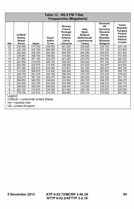
5 November 2013 ATP 6-02.72/MCRP 3-40.3A 95 NTTP 6-02.2/AFTTP 3-2.18
Table 13. HQ II FM T-Net Frequencies (Megahertz)
Net
CONUS Alaska Hawaii Korea Japan
Guam within 12 nm
Norway France
Portugal Greece Estonia Latvia
Lithuania
Italy Spain
Belgium Netherlands Luxembourg
Turkey
DenmarkUK
Germany Slovenia Slovak
Republic Romania Bulgaria
Czech Republic Hungary Poland Iceland Albania Croatia
20 235.050 314.700 235.050 261.050 252.925 252.725 525.100 19 225.150 322.700 289.050 379.325 374.425 374.125 373.800 18 252.925 326.300 293.550 269.350 264.550 265.875 257.400 17 239.950 369.700 298.650 316.550 308.550 315.875 310.000 16 271.950 381.100 303.275 291.250 283.875 284.950 280.325 15 267.850 314.675 308.750 359.350 344.925 357.150 355.675 14 262.450 322.675 314.450 338.950 337.025 342.575 344.525 13 257.250 326.275 235.050 373.875 357.325 363.275 363.700 12 314.450 369.675 314.450 399.450 386.800 387.850 399.775 11 308.750 381.075 308.750 386.550 379.725 379.225 378.025 10 303.275 381.100 303.275 306.500 292.425 292.200 291.175 9 298.650 369.700 298.650 310.900 300.725 298.575 298.275 8 293.550 322.700 293.550 253.000 245.725 248.275 246.775 7 289.050 326.300 289.050 328.400 312.925 336.025 335.475 6 284.150 314.675 235.050 241.450 235.100 240.875 240.525 5 279.750 322.675 314.450 283.850 270.175 270.025 267.325
Legend: CONUS—continental United States nm—nautical mile UK—United Kingdom

96 ATP 6-02.72/MCRP 3-40.3A 5 November 2013 NTTP 6-02.2/AFTTP 3-2.18
This page intentionally left blank.
5 November 2013 ATP 6-02.72/MCRP 3-40.3A 97 NTTP 6-02.2/AFTTP 3-2.18
Appendix L HAVE QUICK TECHNICAL DATA
1. Word-of-day (WOD)
a. General. The WOD is a 36-digit transmission security code inserted into the radio by an operator. It is stored in the radio and programs the system with the hopping pattern, hopping rate, and conferencing selection. The WOD is provided on Mylar tape issued in canisters containing a 35-day allotment. Planners must direct the use of these tapes when notified by the United States (US) Naval Observatory (users of older HAVE QUICK (HQ) II equipment will have to manually request time after-a-leap-second correction to update system time.) The National Security Agency produces and distributes WOD through communications security (COMSEC) channels. The tapes provided are KAL-9200 and KAL-269.
(1) The KAL-9200, HQ Worldwide Electronic Counter-Countermeasures Settings, is used outside the continental US (CONUS), as defined by the Joint COMSEC Management Office. All combat units should order this item. Due to potential interference with Federal Aviation Administration safety of flight functions, do not use KAL-9200 within line-of-sight of CONUS facilities.
(2) The KAL-269 (CONUS WOD) is used in CONUS, as defined by the Joint COMSEC Management Office. Ordering instructions are contained in COMSEC Material System-21.
b. Ordering and Reproducing the WOD.
(1) Order WOD canisters through the supporting COMSEC custodian, per COMSEC Material System-21. Units must store and maintain sufficient WOD materials for their operations. WOD materials are not required for system checkout or maintenance.
(2) The KAL-9200 is distributed in the quantities needed to support units equipped with HQ radios. The Joint COMSEC Management Office, MacDill Air Force Base (AFB), Florida is the controlling authority (CONAUTH) for KAL-9200. For an electronic message, address the message to: Joint COMSEC Management Office, Macdill AFB FL 33621-5504.
(3) The following policies apply to reproducing the KAL-9200 WOD segment:
(a) Only HQ users with flying missions may reproduce it locally by a method authorized for classified material. Limit quantities to the minimum mission requirement.
(b) Forward requests for local reproduction from non-flying units through COMSEC channels to the CONAUTH. Requests must explain why the unit cannot meet WOD requirements with a small number of canisters.
98 ATP 6-02.72/MCRP 3-40.3A 5 November 2013 NTTP 6-02.2/AFTTP 3-2.18
(c) Control original extracted WOD segments according to Service COMSEC directives.
(d) Special control procedures, such as hand receipts and copy counts, are not required for reproduced copies of the daily extracted WOD segment. Treat the current and next day’s segments as unclassified. Control the complete canister as CONFIDENTIAL material according to Service directives.
(4) The following policies apply to distributing, reproducing, and using KAL-269 WOD segments:
(a) The KAL-269 is distributed through COMSEC channels. After reaching the unit level, treat the KAL-269 in accordance with Service regulations.
(b) Reproduce KAL-269 as necessary at the unit level.
(c) The Joint COMSEC Management Office, MacDill AFB, Florida 33621-5504, is the CONAUTH for KAL-269.
c. WOD Dissemination. Generally, WOD is given to users, one segment (day) at a time. It is changed periodically, normally once a day. The WOD may be issued as current plus following day. The segment in use always has a date that matches the current Zulu date. Those operators who anticipate mission requirements exceeding one day must take the next day’s WOD also. Some users may require the entire canister. The AN/CYZ-10, simple key loader, or Secure DTD2000 System with the correct update software, can load multiple WOD (MWOD) information.
2. Time-of-day (TOD)
a. General: HQ radios require accurate timing systems and a precise time reference, TOD, to maintain synchronization while FH in the active mode of operation. Timing systems integral to the HQ radios provide frequency and timing requirements for standard and FH radio operation. Coordinated Universal Time (UTC) serves as the precise time reference that is used to initialize and align all HQ radio timing systems to a common time base. Alignment and accuracy of HQ timing sources ensures users of synchronized operation within their nets and precludes interference with, and by, other HQ nets.
(1) HQ radio timing systems are configured with temperature controlled, quartz crystal oscillators, as is typical of tactical systems. This system provides sufficient stability to maintain TOD accuracy. Operational experience has proven that frequent TOD updates improve HQ communication reliability.
(2) The TOD reference signal used to initialize and synchronize all HQ radio operation is provided as UTC and is either transmitted to or manually inserted into the radio. TOD is transmitted to a radio either by another HQ radio, over-the-air (OTA), or through an electrical bus or
5 November 2013 ATP 6-02.72/MCRP 3-40.3A 99 NTTP 6-02.2/AFTTP 3-2.18
interface from an external TOD reference source. When transmitted to the radio, UTC is presented in a digital format.
b. TOD Sources. TOD initialization and updating of HQ radio may be obtained from a variety of sources.
(1) The primary TOD distribution source needs to be from a single master radio frequency (RF) source. In today’s global environment, Global Positioning System (GPS) satellites serve as the primary master RF source. The selected method of updating a HQ radio with TOD may be dictated by the HQ platform capability or based upon mission expediency.
(2) Airborne Warning and Control System (AWACS)/Joint Surveillance Target Attack Radar System (JSTARS)/RIVET JOINT. In the absence of a GPS, AWACS, JSTARS, or RIVET JOINT aircraft are the preferred choice for TOD in an operational area. These aircraft are equipped with GPS receivers and rubidium oscillators. Platforms such as these can provide accurate TOD OTA to any HQ radio, in the absence of GPS, for a period of up to 30 days. Also, time signal sets, such as the AN/TRC-187, can serve as a primary TOD source. The AN/TRC-187 contains a GPS receiver, HQ radio, and other interfaced circuitry to support the transmission and reception of TOD data. In addition, the AN/TRC-187 can receive accurate time from another time signal set via telephone lines. It can pass TOD OTA to any HQ radio. AN/TRC-187s are normally installed at forward and rear tactical air control facilities.
Note: In some instances it may be more practical for a land-based unit such as a control and reporting center, sector air operations center, etc., to act as the TOD source since the land based units in theater usually operate around the clock as opposed to airborne platforms which have limited on-station time.
c. GPS. GPS receivers are installed or affiliated with most ships, aircraft, tactical air control system shelters, vehicles, and manpack units. The deployment of GPS receivers with an HQ TOD output interface has established it as a means of initializing and updating HQ radios with TOD. Also, it is the most accurate of the available sources, since GPS contains a combination of cesium beam and rubidium oscillators whose output signals are constantly monitored and referenced to US Naval Observatory UTC. The initially fielded GPS receivers are linked to the HQ radios either directly, by means of a cable, or through an electrical bus arrangement. Where system design warrants, future HQ systems will contain embedded GPS receivers.
Note: Many radios equipped with GPS TOD receivers have no way to indicate if a valid TOD was received via GPS other than to ops-check it with another collocated radio or another user (there is no audible tone as in a TOD OTA transfer).
100 ATP 6-02.72/MCRP 3-40.3A 5 November 2013 NTTP 6-02.2/AFTTP 3-2.18
(1) HQ Radios. Operators can use HQ radios that have recently received a TOD update from a single master RF source as a TOD source. The time will be most accurate immediately after the radio has received the update.
(2) Emergency Time Start. Use emergency time start as a last resort if no UTC source is available to use as an emergency activation procedure. If synchronization is lost and an accurate timing source is not available, users within a net may synchronize themselves. One HQ radio can self-generate an arbitrary TOD and then act as a master clock to synchronize all other radios on the net. Other radios with the proper TOD will not be able to communicate with the self-started net in the active mode, and nets with different TODs may receive mutual interference if they are within range. Make every effort to acquire TOD from GPS, AWACS, JSTARS, RIVET JOINT, or HQ radios before using the emergency activation procedure.
d. TOD and Day of Month (DOM). In addition to requiring TOD, HQ II radios also require the current DOM so the correct MWOD segment can be loaded from internal memory to initialize the radio for that day’s operation. Users can acquire DOM information in a time update from a HQ II radio already loaded with the current DOM or they can enter it manually.
(1) If this date information is not available, the user can enter the current DOM manually and then self-start the radio’s clock.
(2) For HQ II radios to transmit DOM after an emergency self-activation, enter the DOM before the TOD, or only the TOD will be transmitted. There is no manual input for day of year. The only way to receive day of year is when the original TOD is received from GPS.
e. TOD Procedural Considerations.
(1) TOD Initialization. Although the principal way of initializing and updating HQ radios will be by means of a single master RF source, there are additional facilities/terminals available to provide TOD, as previously noted. The appropriate initialization method for a particular situation depends on the tactical environment, and only the commander can make that determination. There are, however, several planning considerations to remember when selecting TOD initialization methods.
(a) Operators must receive initial TOD in the normal mode on a single ultra high frequency frequency. When operating in the active mode, operators can only receive TOD updates from radios operating in the same net.
(b) Designation of alternate frequencies and beacon sources for transmitting initial and updated TOD to net members is another important consideration. Without an alternate, enemy jamming of the primary frequency can cripple an HQ net by disrupting time
5 November 2013 ATP 6-02.72/MCRP 3-40.3A 101 NTTP 6-02.2/AFTTP 3-2.18
synchronization. If the primary time source fails, two-way transfer of TOD responsibilities to an alternate source must occur.
(c) In the case of RF beacon frequency loss, all platforms will revert to individual platform GPS until an alternate RF beacon is established.
(2) Leap Second.
(a) Leap Second Planning. Twice a year, at midnight UTC, on 31 December and 30 June, the UTC advances or retards by one second. This is known as a leap second. Leap seconds are used, when needed, to compensate for variations in the Earth’s rotation rate and to keep UTC aligned with astronomical time (Universal Time 1).
(b) The Leap-Second Rollback Problem. At midnight, when a leap second occurs, a net composed of radios relying on different sources of time (i.e., GPS and non-GPS) have the potential of being non-interoperable after a leap second event if the radios are commanded to receive a new TOD. Since existing HQ II radios do not have the provision for manual input of an expected leap second or for automatic rollback at the designated time, operators must use the following measures.
• A leap second occurrence is identified several months prior to its occurrence. For HQ II equipment, the appropriate operational procedure is to require all active units, operating through midnight on those days, to command their radios to accept a new TOD message from an identified GPS-based timing source.
• GPS automatically corrects for the leap second and continuously provides accurate UTC to GPS-equipped radios. Most aircraft are equipped with GPS receivers to synchronize their HQ radios with UTC. Operators can use radios that have a source of GPS time available to accept a corrected TOD after a leap second event and thereby maintain proper radio operation. It is the responsibility of the platform, operator, or pilot to initiate this sequence.
• Units that do not have GPS receivers will continue to operate on time that has not been corrected for the leap second. TOD re-initialization of non-GPS-clocked radios by a GPS-clocked radio is required at this point to begin operation with time that has been corrected for the leap second.
3. Net Identification Number
The three-digit net identification number is manually entered into the radio similar to the manual assignment of a single frequency. The number assigns the net type and group on which a given radio net will operate. Also, the net number
102 ATP 6-02.72/MCRP 3-40.3A 5 November 2013 NTTP 6-02.2/AFTTP 3-2.18
provides an offset in the hopping sequence upon which radios in that net will initiate their hop sequence. The net number interfaces the nets which precludes self-interference among the nets since all systems possess the same WOD and TOD. Net number assignments are made by planners based upon the number of nets accommodated by WOD in a geographical region. Operators may apply net number replication when sufficient geographical separation permits.
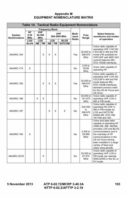
5 November 2013 ATP 6-02.72/MCRP 3-40.3A 103 NTTP 6-02.2/AFTTP 3-2.18
Appendix M EQUIPMENT NOMENCLATURE MATRIX
Table 14. Tactical Radio Equipment Nomenclature
System Nomenclature
Frequency Band
Multi-band Radio
Freq Range
Select features, waveforms and modes
of operation
HF 2-30 MHz
VHF30-300 MHz
UHF 300-3000 MHz
LOS/ BLOS
LOS LOS BLOSAM FM AM FM SATCOM
AN/ARC-164 X X X Yes 30.000 to 399.975
MHz
Voice radio capable of operating UHF LOS HQ II ECCM in AM and FM mode (FM available for VHF/UHF with MXF-243 control) features MIL-STD-1553B interfaces.
AN/ARC-174 X No 2.00 to 29.99 MHz
Voice radio capable of operating HF.
AN/ARC-182 X X X Yes 30.000 to 399.975
MHz
Voice radio capable of operating UHF LOS HQ II ECCM in AM and FM mode features MIL-STD-1553B interfaces, standard avionics radio for the US Air Force and US Army.
AN/ARC-186 X X No 30.000 to 151.975
MHz
Voice radio capable of operating VHF LOS in AM or FM mode.
AN/ARC-187 X X X No
225.000 to
399.975 MHz
Voice radio capable of operating HQ UHF in AM or FM modes for LOS and SATCOM DAMA MIL STD-188-181/182 and 183.
AN/ARC-190 X No 2.000 to 29.999 MHz
Voice and data radio capable of operating HF USB/LSB, ISB, AM/AM, provides LOS and BLOS communications and is the mainstay of HF communications in the US Air Force having been installed in a large variety of fixed and rotary wing aircraft.
AN/ARC-201D X No 30.000 to 87.975 MHz
Voice radio capable of operating VHF LOS in FM mode can operate SINCGARS in the SC or FH mode.
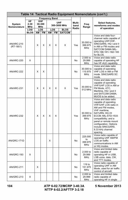
104 ATP 6-02.72/MCRP 3-40.3A 5 November 2013 NTTP 6-02.2/AFTTP 3-2.18
Table 14 Tactical Radio Equipment Nomenclature (con’t.)
System Nomenclature
Frequency Band
Multi-band Radio
Freq Range
Select features, waveforms and modes
of operation
HF 2-30 MHz
VHF30-300 MHz
UHF 300-3000 MHz
LOS/ BLOS
LOS LOS BLOSAM FM AM FM SATCOM
AN/ARC-210 (RT-1851)
X X X X X Yes 30.000 to 399.975
MHz
Voice and data four-channel radio capable of operating UHF/VHF, SINCGARS, HQ I and II in AM or FM modes and SATCOM DAMA MIL-STD-188-181/-182/-183 for BLOS.
AN/ARC-220 X No 2.000 to 29.999 MHz
Voice and data radio capable of operating HF has HF-ALE capability.
AN/ARC-222 X X No 30.000 to 115.975
MHz
Voice and data radio capable of operating VHF LOS in AM or FM mode. SINCGARS SC mode.
AN/ARC-231 X X X X X Yes 30.000 to 512 MHz
Voice and data radio capable of operating VHF/UHF LOS in AM or FM Mode, ATC, Maritime, HQ I and II and SATCOM DAMA; MUOS to be added.
AN/ARC-232 X X X X Yes 30.000 to 399.975
MHz
Voice and data radio capable of operating VHF/UHF LOS radio in AM and FM modes, VHF maritime, SATURN; HQ I/II ECCM; MIL-STD-1533 compatibility; and a panel or remote mount configuration. Options include SINCGARS, 8.33 kHz channel spacing.
AN/GRC-171D X No
225.000 to
399.975 MHz
Voice radio capable of operating UHF AM/FM LOS air traffic communications in AM or HQ modes.
AN/GRC-193 X No 2.000 to 29.999 MHz
Voice and limited data radio capable of operating HF in USB, LSB voice, data, CW, and TTY modes.
AN/GRC-211 X No 116 to
151.975 MHz
Voice radio capable of operating UHF in AM Mode, used for air traffic control of aircraft.
AN/GRC-213 X No 2.000 to 29.999 MHz
Voice and limited data radio capable of operating HF in single
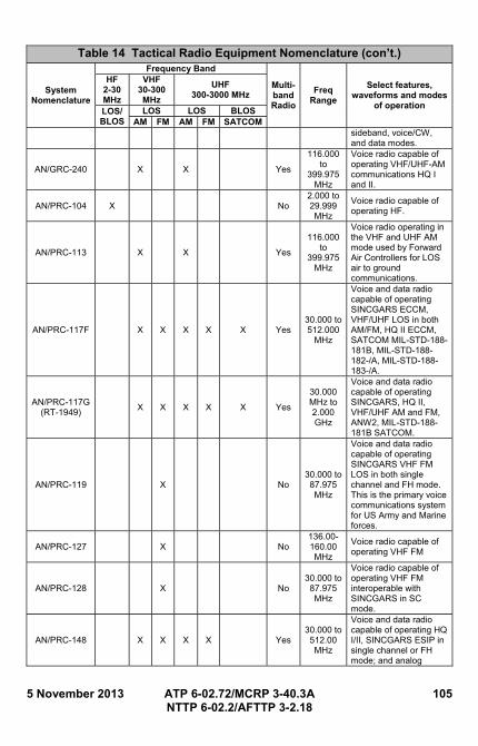
5 November 2013 ATP 6-02.72/MCRP 3-40.3A 105 NTTP 6-02.2/AFTTP 3-2.18
Table 14 Tactical Radio Equipment Nomenclature (con’t.)
System Nomenclature
Frequency Band
Multi-band Radio
Freq Range
Select features, waveforms and modes
of operation
HF 2-30 MHz
VHF30-300 MHz
UHF 300-3000 MHz
LOS/ BLOS
LOS LOS BLOSAM FM AM FM SATCOM
sideband, voice/CW, and data modes.
AN/GRC-240 X X Yes
116.000 to
399.975 MHz
Voice radio capable of operating VHF/UHF-AM communications HQ I and II.
AN/PRC-104 X No 2.000 to 29.999 MHz
Voice radio capable of operating HF.
AN/PRC-113 X X Yes
116.000 to
399.975 MHz
Voice radio operating in the VHF and UHF AM mode used by Forward Air Controllers for LOS air to ground communications.
AN/PRC-117F X X X X X Yes 30.000 to 512.000
MHz
Voice and data radio capable of operating SINCGARS ECCM, VHF/UHF LOS in both AM/FM, HQ II ECCM, SATCOM MIL-STD-188-181B, MIL-STD-188-182-/A, MIL-STD-188-183-/A.
AN/PRC-117G (RT-1949)
X X X X X Yes
30.000 MHz to 2.000 GHz
Voice and data radio capable of operating SINCGARS, HQ II, VHF/UHF AM and FM, ANW2, MIL-STD-188-181B SATCOM.
AN/PRC-119 X No 30.000 to 87.975 MHz
Voice and data radio capable of operating SINCGARS VHF FM LOS in both single channel and FH mode. This is the primary voice communications system for US Army and Marine forces.
AN/PRC-127 X No 136.00-160.00 MHz
Voice radio capable of operating VHF FM
AN/PRC-128 X No 30.000 to 87.975 MHz
Voice radio capable of operating VHF FM interoperable with SINCGARS in SC mode.
AN/PRC-148 X X X X Yes 30.000 to 512.00 MHz
Voice and data radio capable of operating HQ I/II, SINCGARS ESIP in single channel or FH mode; and analog
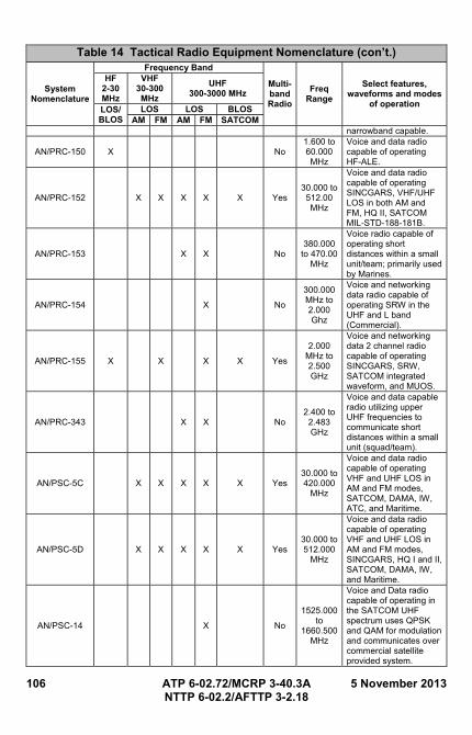
106 ATP 6-02.72/MCRP 3-40.3A 5 November 2013 NTTP 6-02.2/AFTTP 3-2.18
Table 14 Tactical Radio Equipment Nomenclature (con’t.)
System Nomenclature
Frequency Band
Multi-band Radio
Freq Range
Select features, waveforms and modes
of operation
HF 2-30 MHz
VHF30-300 MHz
UHF 300-3000 MHz
LOS/ BLOS
LOS LOS BLOSAM FM AM FM SATCOM
narrowband capable.
AN/PRC-150 X No 1.600 to 60.000 MHz
Voice and data radio capable of operating HF-ALE.
AN/PRC-152 X X X X X Yes 30.000 to 512.00 MHz
Voice and data radio capable of operating SINCGARS, VHF/UHF LOS in both AM and FM, HQ II, SATCOM MIL-STD-188-181B.
AN/PRC-153 X X No 380.000
to 470.00 MHz
Voice radio capable of operating short distances within a small unit/team; primarily used by Marines.
AN/PRC-154 X No
300.000 MHz to 2.000 Ghz
Voice and networking data radio capable of operating SRW in the UHF and L band (Commercial).
AN/PRC-155 X X X X Yes
2.000 MHz to 2.500 GHz
Voice and networking data 2 channel radio capable of operating SINCGARS, SRW, SATCOM integrated waveform, and MUOS.
AN/PRC-343 X X No 2.400 to 2.483 GHz
Voice and data capable radio utilizing upper UHF frequencies to communicate short distances within a small unit (squad/team).
AN/PSC-5C X X X X X Yes 30.000 to 420.000
MHz
Voice and data radio capable of operating VHF and UHF LOS in AM and FM modes, SATCOM, DAMA, IW, ATC, and Maritime.
AN/PSC-5D X X X X X Yes 30.000 to 512.000
MHz
Voice and data radio capable of operating VHF and UHF LOS in AM and FM modes, SINCGARS, HQ I and II, SATCOM, DAMA, IW, and Maritime.
AN/PSC-14 X No
1525.000 to
1660.500 MHz
Voice and Data radio capable of operating in the SATCOM UHF spectrum uses QPSK and QAM for modulation and communicates over commercial satellite provided system.
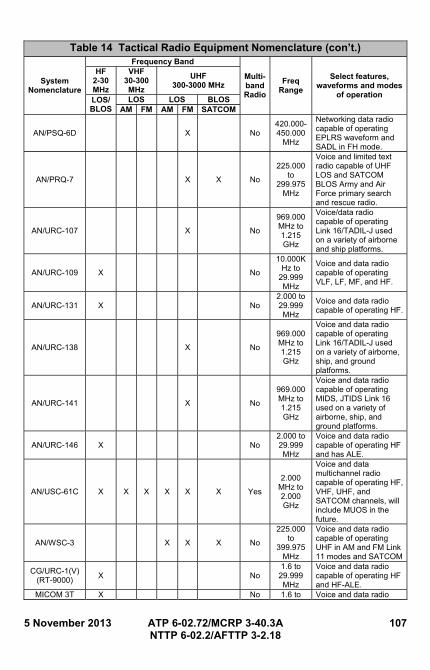
5 November 2013 ATP 6-02.72/MCRP 3-40.3A 107 NTTP 6-02.2/AFTTP 3-2.18
Table 14 Tactical Radio Equipment Nomenclature (con’t.)
System Nomenclature
Frequency Band
Multi-band Radio
Freq Range
Select features, waveforms and modes
of operation
HF 2-30 MHz
VHF30-300 MHz
UHF 300-3000 MHz
LOS/ BLOS
LOS LOS BLOSAM FM AM FM SATCOM
AN/PSQ-6D X No 420.000-450.000
MHz
Networking data radio capable of operating EPLRS waveform and SADL in FH mode.
AN/PRQ-7 X X No
225.000 to
299.975 MHz
Voice and limited text radio capable of UHF LOS and SATCOM BLOS Army and Air Force primary search and rescue radio.
AN/URC-107 X No
969.000 MHz to 1.215 GHz
Voice/data radio capable of operating Link 16/TADIL-J used on a variety of airborne and ship platforms.
AN/URC-109 X No
10.000KHz to
29.999 MHz
Voice and data radio capable of operating VLF, LF, MF, and HF.
AN/URC-131 X No 2.000 to 29.999 MHz
Voice and data radio capable of operating HF.
AN/URC-138 X No
969.000 MHz to 1.215 GHz
Voice and data radio capable of operating Link 16/TADIL-J used on a variety of airborne, ship, and ground platforms.
AN/URC-141 X No
969.000 MHz to 1.215 GHz
Voice and data radio capable of operating MIDS, JTIDS Link 16 used on a variety of airborne, ship, and ground platforms.
AN/URC-146 X No 2.000 to 29.999 MHz
Voice and data radio capable of operating HF and has ALE.
AN/USC-61C X X X X X X Yes
2.000 MHz to 2.000 GHz
Voice and data multichannel radio capable of operating HF, VHF, UHF, and SATCOM channels, will include MUOS in the future.
AN/WSC-3 X X X No
225.000 to
399.975 MHz
Voice and data radio capable of operating UHF in AM and FM Link 11 modes and SATCOM
CG/URC-1(V) (RT-9000)
X No 1.6 to
29.999 MHz
Voice and data radio capable of operating HF and HF-ALE.
MICOM 3T X No 1.6 to Voice and data radio
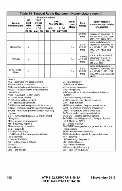
108 ATP 6-02.72/MCRP 3-40.3A 5 November 2013 NTTP 6-02.2/AFTTP 3-2.18
Table 14 Tactical Radio Equipment Nomenclature (con’t.)
System Nomenclature
Frequency Band
Multi-band Radio
Freq Range
Select features, waveforms and modes
of operation
HF 2-30 MHz
VHF30-300 MHz
UHF 300-3000 MHz
LOS/ BLOS
LOS LOS BLOSAM FM AM FM SATCOM
29.999 MHz
capable of operating HF and HF-ALE USB, LSB, AME, CW, ARQ, FEC.
RT-2400A X No 2.0 to
29.999 MHz
Voice and data radio capable of operating HF and HF-ALE USB, LSB, AME, CW, ARQ, and FEC.
TMR-90 X No 1.5 MHz to 29.999
MHz
Voice radio capable of operating HF and HF-ALE USB, LSB, ISB, AM, and AME.
URG-III (RT-2200)
X No 1.5 to
29.999 MHz
Voice and data radio capable of operating HF and HF-ALE USB, LSB, ISB, AM, AME, CW, and NBFM.
Legend: ALE—automatic link establishment AM—amplitude modulation AME—amplitude modulation equivalent ANW2—Adaptive Networking Wideband Waveform ARQ—Automatic Repeat Query ATC—air traffic control BLOS—beyond line-of-sight CW—continuous waveform DAMA—demand assigned multiple access ECCM—electronic counter-countermeasures EPLRS—enhanced position location reporting system ESIP—Enhanced SINCGARS Improvement Program FEC—forward error correction FH—frequency hopping FM—frequency modulation GHz—gigahertz HF—high frequency HF-ALE—high frequency-automatic link establishment HQ—HAVE QUICK ISB—independent sideband JTIDS— kHz—kilohertz LOS—line of sight
LF—low frequency LSB—lower sideband MF—medium frequency MHz—megahertz MIDS—multifunctional information distribution system MIL-STD—military standard MUOS—mobile user objective system MXF—multi-function NBFM—narrowband frequency modulation QAM—quadrature amplitude modulation QPSK—quadrature phase shift keyed SADL—situation awareness data link SATCOM—satellite communications SATURN—Second generation Anti-jam Tactical UHF Radio for NATO SC—single-channel SINCGARS—single-channel ground and airborne radio system SRW—soldier radio waveform TADIL-J—tactical digital information link-Joint TTY—teletype UHF—ultrahigh frequency US—United States USB—upper sideband VHF—very high frequency VLF—very low frequency
5 November 2013 ATP 6-02.72/MCRP 3-40.3A 109 NTTP 6-02.2/AFTTP 3-2.18
REFERENCES
JOINT PUBLICATIONS
Joint Publication (JP) 1-02, Department of Defense Dictionary of Military and Associated Terms, Amended through 15 April 2012 JP 3-09.3, Close Air Support, 08 July 2009 JP 5-0, Joint Operation Planning, 11 August 2011 JP 6-01, Joint Electromagnetic Spectrum Management Operations, 20 March 2012
AIR FORCE PUBLICATIONS
AFI 33-106, Managing High Frequency Radios, Personal Wireless Communication Systems, and the Military Affiliate Radio System, 9 January 2002 AFI 33-118, Electromagnetic Spectrum Management, 18 July 2005 AFI 33-360, Publications and Forms Management Program, 18 May 2006
ARMY PUBLICATIONS
FMI 6-02.45, Signal Support to Theater Operations, 5 Jul 2007 FM 6-02.53, Tactical Radio Operations, 5 August 2009 FM 6-02.70, Army Electromagnetic Spectrum Operations, 20 May 2010
MARINE CORPS PUBLICATIONS
MCWP 3-40.1 w-Chg 1, MAGTF Command and Control, 27 September 2005 MCWP 3-40.3, Communications and Information Systems, 8 January 2010 MCRP 3-40.3B, Radio Operator’s Handbook, 10 July 2001
NAVY PUBLICATIONS
OPNAVINST F2300.44H, Command, Control, Communications and Computer Requirements for Navy Ships, Military Sealift Command Ships, Coast Guard Cutters, Transportable Facilities Designated Craft, Portable Radio Users, Major Shores Communication Stations, and Maritime Operations, 28 June 2011 OPNAVINST 2400.20F, Navy Management of the Radio Frequency Spectrum, 19 July 2007 NAVAIR 01-E2AAB-1CH2, NATOPS Flight Manual Navy Model E-2C Plus Aircraft, 30 September 1999
COAST GUARD PUBLICATIONS
COMDTINST M2000.3 (Series), Telecommunications Manual (TCM), 19 June 2008 COMDTINST M2000.4 (Series), Telecommunications Plan (TCP), 20 April 1988 COMDTINST M2400.1 (Series), Spectrum Management Policies and Procedures, 22 September 2006
110 ATP 6-02.72/MCRP 3-40.3A 5 November 2013 NTTP 6-02.2/AFTTP 3-2.18
OTHER PUBLICATIONS
ACP 190(C), Guide to Spectrum Management in Military Operations, September 2007 CJCSI 3320.01C, Electromagnetic Spectrum Use in Joint Military Operations, 22 February 2011
5 November 2013 ATP 6-02.72/MCRP 3-40.3A 111 NTTP 6-02.2/AFTTP 3-2.18
GLOSSARY
PART I—ABBREVIATIONS AND ACRONYMS Numbers 2G second generation 3G third generation A AADS amphibious assault direction system ABCS Army Battle Command System ACE aviation combat element (USMC) ACS amphibious command ship ADDSI Army data distribution system interface AFB Air Force Base AFI Air Force instruction AFKDMS Air Force key data management system AFP ARC-210 fill program AFTTP Air Force tactics, techniques, and procedures AGC automatic gain control AJ anti-jam ALE automatic link establishment aka also known as ALSA Air Land Sea Application (Center) AM amplitude modulation AMD automatic message display AME amplitude modulation equivalent ANCD AN/CYZ-10 Data Transfer Device ANW2 Adaptive Networking Wideband Waveform AOC air operations center AOR area of responsibility ARFOR Army forces ARQ Automatic Repeat request, known as Automatic Repeat
Query ASOC air support operations center ATF amphibious task force ATO air tasking order AWACS Airborne Warning and Control System B BFT blue force tracking BLOS beyond line-of-sight C C2 command and control
112 ATP 6-02.72/MCRP 3-40.3A 5 November 2013 NTTP 6-02.2/AFTTP 3-2.18
CADD Combined Arms Doctrine Directorate CAS close air support CATF commander, amphibious task force CBP Custom and Border Protection CCI controlled cryptographic items CE command element (MAGTF) CEOI communications-electronics operating instructions CH channel CJCS Chairman of the Joint Chiefs of Staff CLR combat logistics regiment; clear CND computer network defense COMM commercial COMSEC communications security CONAUTH controlling authority CONUS COTS
continental US commercial off-the-shelf
CRC control and reporting center CRYPTO cryptographic cryptonet cryptographic network CSAR combat search and rescue CSEP Single-Channel Radio Electronic Counter Measure
Package CSG carrier strike group CT cipher text CW continuous waveform CWC composite warfare commander D DAMA demand assigned multiple access DOD Department of Defense DOM day of month DSN Defense Switched Network E ECCM electronic counter-countermeasures E-Lite enhanced position location reporting system-Lite EP electronic protection EPLRS enhanced position location reporting system ERF electronic remote fill ESIP Enhanced SINCGARS Improvement Program EW electronic warfare F FBCB2 Force Battle Command Brigade and Below FCC Federal Communications Commission
5 November 2013 ATP 6-02.72/MCRP 3-40.3A 113 NTTP 6-02.2/AFTTP 3-2.18
FEC forward error correction FEMA Federal Emergency Management Agency FFH FH
fast frequency hopping frequency hopping
FH-M frequency hopping-master FM frequency modulation FMA-net FMT-net
frequency management A network frequency management training network
FOT frequency of optimum transmission G GCE ground combat element (MAGTF) GHz gigahertz GPS Global Positioning System H HDR high data rate HF high frequency HF-ALE high frequency-automatic link establishment HFGCS High Frequency Global Communications System HQ HAVE QUICK; HQ I HAVE QUICK I HQ II HAVE QUICK II I IA information assurance ID identification IP internet protocol ISB independent sideband ITU International Telecommunications Union J J3 Operations Directorate of the Joint Staff Command, Control, Communications, and Computers
Systems Directorate of the Joint Staff JACS joint automated communication-electronics operating
instructions system JCEOI joint communications-electronics operating instructions JCS Joint Chiefs of Staff JFC joint force commander JFLCC joint force land component commander JFMO joint frequency management office JITC joint interoperability test command JP joint publication JSME joint spectrum management element JSTARS Joint Surveillance Target Attack Radar System
114 ATP 6-02.72/MCRP 3-40.3A 5 November 2013 NTTP 6-02.2/AFTTP 3-2.18
JTF joint task force JTIDS Joint Tactical Information Distribution System JTRS joint tactical radio system K KEK key encryption key kHz kilohertz km kilometer L LCD liquid crystal display LF low frequency LOS line of sight LP linking protection LQA link quality analysis LSB lower sideband LUF lowest usable frequency LVT low volume terminal M MAGTF Marine air-ground task force MARFOR Marine Corps forces MBITR multiband inter/intra team radio MCEB Military Communications-Electronics Board MCRP Marine Corps reference publication MF MHz
medium frequency megahertz
MIDS multifunctional information distribution system MIL-STD military standard MLG Marine logistics group MTTP multi-Service tactics, techniques, and procedures MSC major subordinate command MUF MUOS
maximum usable frequency mobile user objective system
MWOD multiple word-of-day N NATO North Atlantic Treaty Organization NAVFOR Navy forces NBFM narrowband frequency modulation NCS net control station NETOPS network operations NIPRNET Nonsecure Internet Protocol Router Network NOSC network operations and security center NSA National Security Agency NTIA National Telecommunications and Information
5 November 2013 ATP 6-02.72/MCRP 3-40.3A 115 NTTP 6-02.2/AFTTP 3-2.18
Administration NTTP Navy tactics, techniques, and procedures NVIS near vertical incident sky waves NWDC Navy Warfare Development Command O OPTASK operation task OTA over the air OTC officer in tactical command P PCS primary control ship PT plain text PTT push-to-talk Q QAM quadrature amplitude modulation QPSK quadrature phase shift keyed R R/T receive/transmit RBECS Revised Battlefield Electronic Communications,
Electronics, Intelligence, and Operations (CEIO) System RDS radio data system RF radio frequency ROK Republic of Korea RS radio set RT remote terminal RX receive S SA situational awareness SADL situation awareness data link SATCOM satellite communications SATURN Second generation Anti-jam Tactical UHF Radio for
NATO SC single-channel SCG SCS
security classification guide secondary control ship
SINCGARS single-channel ground and airborne radio system SIPRNET SECRET Internet Protocol Router Network SKL AN/PYQ-10 Simple Key Loader SOF special operations forces SOI signal of interest
116 ATP 6-02.72/MCRP 3-40.3A 5 November 2013 NTTP 6-02.2/AFTTP 3-2.18
SOP standard operating procedure SPEED Systems Planning, Engineering, and Evaluation Device SRW soldier radio waveform STNOSC Service Theater Network Operations Security Center T TACP tactical air control party TACSAT tactical satellite TADIL-J tactical digital information link-Joint TDMA time division multiple access TDN tactical data network TEK traffic encryption key TI Tactical Internet TOC tactical operations center TOD time of day TRADOC United States Army Training and Doctrine Command TRANSEC transmission security TSK transmission security key TTP tactics, techniques, and procedures TTY teletype TX transmit U UHF ultrahigh frequency URO user readout US United States USAF United States Air Force USCBP United States Customs and Border Protection USCG United States Coast Guard UTC Coordinated Universal Time V VHF VHF-FM
very high frequency very high frequency-frequency modulation
VLF very low frequency VINSON encrypted ultrahigh frequency communications system W WCCS Wing Command and Control System WOC wing operations center (USAF) WOD word-of-day X, Y, Z
5 November 2013 ATP 6-02.72/MCRP 3-40.3A 117 NTTP 6-02.2/AFTTP 3-2.18
PART II—TERMS AND DEFINITIONS
active mode—The frequency-hopping mode of operation for HAVE QUICK radios. (Source: This term and its definition are applicable only in the context of this publication and connot be referenced outside this publication)
air support operations center—(DOD) The principal air control agency of the theater air control system responsible for the direction and control of air operations directly supporting the ground combat element. It coordinates air missions requiring integration with other supporting arms and ground forces. It normally collocates with the Army tactical headquarters senior fire support coordination center within the ground combat element. Also called ASOC. (JP 1-02. Source: JP 3-09.3)
AN/CYZ-10—Data Transfer Device, often called a Filler, Crazy 10, ANCD or DTD, is a United States National Security Agency-developed, portable, hand-held fill device, for securely receiving, storing, and transferring data between compatible cryptographic and communications equipment. It is capable of storing 1,000 keys, maintains an automatic internal audit trail of all security-relevant events that can be uploaded to the LMD/KP, encrypts key for storage, and is programmable. The DTD is capable of keying multiple information systems security (INFOSEC) devices and is compatible with such COMSEC equipment as Single Channel Ground and Airborne Radio System (SINCGARS) radios, KY-57 VINSON, KG-84, and others that are keyed by common fill devices (CFDs). (Source: TB 11-5820-890-12)
AN/PYQ-10—The AN/PYQ-10 Simple Key Loader (SKL) is a ruggedized, portable, hand-held fill device, for securely receiving, storing, and transferring data between compatible cryptographic and communications equipment. The PYQ-10 provides all the functions currently resident in the CYZ-10 and incorporates new features that provide streamlined management of COMSEC key, Electronic Protection (EP) data, and Signal Operating Instructions (SOI). Cryptographic functions are performed by an embedded KOV-21 card developed by the National Security Agency (NSA). The AN/PYQ-10 supports both the DS-101 and DS-102 interfaces, as well as the KSD-64 Crypto Ignition Key. The SKL is backward-compatible with existing End Cryptographic Units (ECU) and forward-compatible with future security equipment and systems,
118 ATP 6-02.72/MCRP 3-40.3A 5 November 2013 NTTP 6-02.2/AFTTP 3-2.18
including NSA’s Key Management Infrastructure. (Source: TM 11-5820-890-10-6)
area of responsibility—(DOD) The geographical area associated with a combatant command within which a geographic combatant commander has authority to plan and conduct operations. Also called AOR. See also combatant command. (JP 1-02. Source: JP 1)
carrier strike group—(DOD) A standing naval task group consisting of a carrier, embarked airwing, surface combatants, and submarines as assigned in direct support, operating in mutual support with the task of destroying hostile submarine, surface, and air forces within the group’s assigned operational area and striking at targets along hostile shore lines or projecting power inland. Also called CSG. (JP 1-02. Source: JP 3-02)
cold start net opening—Method of opening a FH net in which each member loads COMSECand FH data and stands by for receipt of sync time sent electronically by the NCS. (Source: TM 11-5820-890-10-8)
commander, amphibious task force—(DOD) The Navy officer designated in the initiating directives as the commander of the amphibious task force. Also called CATF. (JP 1-02. Source: JP 3-02)
communications security—(DOD) The protection resulting from all measures designed to deny unauthorized persons information of value that might be derived from the possession and study of telecommunications, or to mislead unauthorized persons in their interpretation of the results of such possession and study. Also called COMSEC. (JP 1-02. Source: JP 6-0)
conferencing—The receiver’s ability to accept two simultaneous transmissions on the same network while avoiding the beat note or side tone that is typically present under normal operation, preventing the listeners from understanding either transmission. (Source: This term and its definition are applicable only in the context of this publication and connot be referenced outside this publication)
Coordinated Universal Time—(DOD) An atomic time scale that is the basis for broadcast time signals. Coordinated Universal Time (UTC) differs from International Atomic Time by an integral number of seconds; it is maintained within 0.9 seconds of UT1 (see Universal Time) by introduction of Leap Seconds. The rotational orientation of the Earth, specified by UT1, may be obtained to an accuracy of a tenth of a second by applying the UTC to the increment DUT1 (where DUT1 = UT1-UTC) that is broadcast in code with the time signals. Also called UTC. See also Universal Time; Zulu Time (JP 1-02)
5 November 2013 ATP 6-02.72/MCRP 3-40.3A 119 NTTP 6-02.2/AFTTP 3-2.18
cosite interference—Cosite interference refers to two or more transmitters located near each other that cause jamming or degraded operations. (Source: This term and its definition are applicable only in the context of this publication and connot be referenced outside this publication)
CUE frequency—SC frequency and designated channel used to contact net NCS when caller has non-FH radio or has lost contact with the FH net; may also be used as normal SC channel. (Source: TM 11-5820-890-10-8)
Defense Switched Network—(DOD) Component of the Defense Communications System that handles Department of Defense voice, data, and video communications. Also called DSN. (JP 1-02. Source: JP 6-0)
electronic protection—(DOD) Division of electronic warfare involving actions taken to protect personnel, facilities, and equipment from any effects of friendly or enemy use of the electromagnetic spectrum that degrade, neutralize, or destroy friendly combat capability. Also called EP. See also electronic attack; electronic warfare; electronic warfare support. (JP 1-02. Source: JP 3-13.1)
electronic remote fill (ERF)—Method by which an NCS electronically updates FH data of netmembers and transmits sync time for cold start net openings. (Source: TM 11-5820-890-10-8)
electronic warfare—(DOD) Military action involving the use of electromagnetic and directed energy to control the electromagnetic spectrum or to attack the enemy. Also called EW. See also directed energy; electromagnetic spectrum; electronic attack; electronic protection; electronic warfare support. (JP 1-02. Source: JP 3-13.1)
G-2—Army Deputy Chief of Staff for Intelligence; Army or Marine Corps component intelligence staff officer (Army division or higher staff, Marine Corps brigade or higher staff. (JP 1-02)
G-6—Army or Marine Corps component command, control, communications, and computer systems staff officer; assistant chief of staff for communications, signal staff officer. (JP 1-02)
G-7—Army component information operations staff officer; assistant chief of staff, information engagement, information operations staff officer (ARFOR). (JP 1-02)
Global Positioning System—(DOD) A satellite-based radio navigation system operated by the Department of Defense to provide all military, civil, and commercial users with precise positioning, navigation, and timing. Also called GPS. (JP 1-02. Source: JP 3-14)
120 ATP 6-02.72/MCRP 3-40.3A 5 November 2013 NTTP 6-02.2/AFTTP 3-2.18
GPS Zulu time—Zulu time as acquired by the global positioning satellite (GPS) receiver. (Source: TM 11-5820-890-10-8)
hop rate—The rate at which HAVE QUICK radios switch from one frequency of the hopset to the next. (Source: This term and its definition are applicable only in the context of this publication and connot be referenced outside this publication)
hopping pattern—The specific order in which HAVE QUICK radios switch from one frequency of the hopset to the next. (Source: This term and its definition are applicable only in the context of this publication and connot be referenced outside this publication)
hop sequence—The pattern of frequencies transmitted and received over radios in the net hop. The net ID, mission day and time of day (TOD) are input to the linear sequence generator. The linear sequence generator output and the TRANSEC are input to the KGV-10, whose output determines the pattern of hop. (Source: This term and its definition are applicable only in the context of this publication and connot be referenced outside this publication)
hopset—Frequencies made available for a SINCGARS radio to hop on are called a “Hopset.” A typical hopset consists of what remains of the total 2320 frequencies after protected frequencies, such as commercial television, are removed. Protected frequencies are frequently referred to as "Lockouts." In any case, except for technical purposes, lockouts are treated as an integral part of the hopset. (Source: TM 11-5820-890-10-8)
hot start net opening—Method of opening a FH net in which net operators load all required COMSEC, FH data, and sync time from their ANCD and merely call the NCS to check into the net. (Source: TM 11-5820-890-10-8)
J-3—operations directorate of a joint staff; operations staff section. (JP 1-02)
J-6—communications system directorate of a joint staff; command, control, communications, and computer systems staff section (JP 1-02)
joint force commander—(DOD) A general term applied to a combatant commander, subunified commander, or joint task force commander authorized to exercise combatant command (command authority) or operational control over a joint force. Also called JFC. See also joint force. (JP 1-02. Source: JP 1)
joint task force—(DOD) A joint force that is constituted and so designated by the Secretary of Defense, a combatant commander, a
5 November 2013 ATP 6-02.72/MCRP 3-40.3A 121 NTTP 6-02.2/AFTTP 3-2.18
subunified commander, or an existing joint task force commander. Also called JTF. (JP 1-02. Source: JP 1)
Joint Tactical Information Distribution System—A secure anti-jam point-to-point information distribution system used by all Services to provide the big picture. Also called JTIDS. JTIDS platforms can exchange location for friendly, hostile, and neutral plat-forms and navigation information. Terminals are flexible and can limit the amount of information relayed or received. (Source: TM 11-7021-223-10)
late net entry or late entry—The operator missed the announced net opening time and wishes to enter the net now, the operator left the net for some reason and now wants to re-enter, or sync time in the operator’s radio now differs by more than +/- 4 seconds from that of the net. (Source: TM 11-5820-890-10-8)
loadset—All COMSEC keys, FH data, and sync time required to load all six RT channels for frequency hopping, cipher text mode of communications. (Source: TM 11-5820-890-10-8)
lockout set—Data which prevents transmission/reception on particular frequencies; used for FH by all RT using the hopset that needs the lockout set (may not be needed for some hopsets). (Source: TM 11-5820-890-10-1)
manual channel—SC frequency and designated channel used for transmission and receipt of ERFs during cold start net openings; may also be used for normal SC channel. (Source: TM 11-5820-890-10-8)
mission day—The date of the operation; corresponds to the Julian date. (Source: This term and its definition are applicable only in the context of this publication and connot be referenced outside this publication)
mission set—A block of fill data generated from the Air Force KDMS for loading into a specific radio to perform a specific mission. (Source: This term and its definition are applicable only in the context of this publication and connot be referenced outside this publication)
net control station—Also called NCS. Single designated station per net requiring use of the FH-M mode position and performance of net control tasks; assisted and supported by designated alternate NCS stations as warranted by operational requirements. (Source: TM 11-5820-890-10-8)
net number—A number that selects the specific group of frequencies over which HAVE QUICK radios will hop. It ensures that users on different nets do not hop onto the same frequency at the
122 ATP 6-02.72/MCRP 3-40.3A 5 November 2013 NTTP 6-02.2/AFTTP 3-2.18
same time. (Source: This term and its definition are applicable only in the context of this publication and connot be referenced outside this publication)
normal mode—The single-channel UHF mode of operation for HAVE QUICK radios. (Source: This term and its definition are applicable only in the context of this publication and connot be referenced outside this publication)
pseudo-random—A process with an extremely long period before it repeats itself. It appears to be random, but is actually seed dependent. (Source: This term and its definition are applicable only in the context of this publication and connot be referenced outside this publication)
Rivet Joint—(DOD) A defensive counterair mission that defends airborne national assets which are so important that the loss of even one could seriously impact US warfighting capabilities or provide the enemy with significant propaganda value. Examples of high value airborne assets are Airborne Warning and Control System, Rivet Joint, Joint Surveillance and Target Attack Radar System, and Compass Call. Also called HVAA protection. See also defensive counterair. (Source: JP 3-01)
Secure DTD2000 System—Hand-held fill device that is used to download cryptographic key, SOI, CEOI, JCEOI, and mission planning data to IA equipment and communication systems. The SDS downloads, encrypts, and stores red and black material. (Source: SecureeComm SDSver1.5)
spectrum management—The DOD business area of obtaining, controlling, and ensuring the effective and efficient use of electromagnetic spectrum through the development of policy, practices, and procedures. (Source: JP 6-0)
standard operating procedure—A set of instructions covering those features of operations that lend themselves to a definite or standardized procedures without loss of effectiveness. These procedures are applicable unless ordered otherwise. Also called SOP. (JP 1-02)
time of day—A signal that synchronizes HAVE QUICK radios to a common time base for active mode operation. Also called TOD. (Source: This term and its definition are applicable only in the context of this publication and connot be referenced outside this publication)
traffic encryption key— A traffic encryption key (TEK) enables the SINCGARS radio to operate in a secure, cipher text (CT) mode of communications. The TEK is loaded into the SINCGARS RT
5 November 2013 ATP 6-02.72/MCRP 3-40.3A 123 NTTP 6-02.2/AFTTP 3-2.18
from an ANCD, or other COMSEC fill device, if desired. (Source: TM 11-5820-890-10-8)
transmission security key—The pattern in which the radio selects frequencies to hop on is pseudo-random, as determined by the transmission security key (TSK). Depending upon the number of frequencies available for hopping and the TSK itself, the exact sequence of frequencies used during any one second will not be repeated for long periods of time. (Source: TM 11-5820-890-10-8)
Universal Time—(DOD) A measure of time that conforms, within a close approximation, to the mean diurnal rotation of the Earth and serves as the basis of civil timekeeping. Also called Zulu time. (Formerly called Greenwich Mean Time.) (JP 1-02. Source: JP 5-0)
word-of-day—A transmission security (TRANSEC) variable that defines the sequence of frequencies, the dwell times, and the hopping rates for HAVE QUICK radios in the active mode. Also called WOD. (Source: This term and its definition are applicable only in the context of this publication and connot be referenced outside this publication)
Zulu time—(DOD) See Universal Time. (Source: JP 1-02)

124 ATP 6-02.72/MCRP 3-40.3A 5 November 2013 NTTP 6-02.2/AFTTP 3-2.18
This page intentionally left blank.
ATP 6-02.72 [FM 6-02.72] MCRP 3-40.3A
NTTP 6-02.2 AFTTP 3-2.18
5 November 2013 By Order of the Secretary of the Army
Official: RAYMOND T. ODIERNO General, United States Army
Chief of Staff
GERALD B. O’KEEFE Administrative
Assistant to the Secretary of the Army
1324605
DISTRIBUTION:
Active Army, Army National Guard, and US Army Reserve: Distribute in accordance with the initial distribution number (IDN) 115419, requirements for ATP 6-02.72.
By Order of the Secretary of the Air Force
WALTER D. GIVHAN Major General, US Air Force Commander Curtis E. LeMay Center for Doctrine Development and Education
ACCESSIBILITY: Publications and forms are available on the e-Publishing
Web site at www.e-publishing.af.mil for downloading or ordering.
RELEASABILITY: DISTRIBUTION RESTRICTION: Approved for public release; distribution is unlimited. *Supersedes FM 6-02.72, 6-02.74, 6.02-771/MCRP 3-40.3A, 3-40.3E, 3-40.3F/NTTP 6-02.2, 6-02.6, 6-02.7/AFTTP 3-2.18, 3-2.48, 3-2.49, dated June 2002, November 2007, May 2004 respectively.

This page intentionally left blank.

This page intentionally left blank.

This page intentionally left blank.


MARINE CORPS PCN: 144 00007 00 PIN:103715-000