Embed Size (px)
DESCRIPTION
mcr LAM louver smoke exhaust vents, mcr LAM-N louver air intake vents
Citation preview
ul. Grzegorza z Sanoka 2 80-408 Gdańsk
tel. +48 58 341 42 45 tel./fax +48 58 341 39 85
TECHNICAL AND OPERATIONAL DOCUMENTATION
mcr LAM louver smoke exhaust vents
mcr LAM-N louver air intake vents
Gdańsk 7.07.2009 ver. 0.0.2
MCR LAM SHUTTER HATCHES TECHNICAL AND OPERATIONAL DOCUMENTATION
Strona 2 z 14
CONTENTS 1. INTRODUCTION .................................................................................................... 3
2. PURPOSE OF THE DEVICE.................................................................................. 3
3. CONSTRUCTION AND THE PRINCIPLE OF OPERATION .................................. 3
4. TRANSPORT AND DELIVERY .............................................................................. 4
5. ASSEMBLY OF THE DEVICE ................................................................................ 5
6. FITTING A VENT ON A ROOF (examples). ........................................................... 6
7. METHODS OF MOUNTING A VENT IN A WALL (examples). ............................... 7
8. CONTROL JETS..................................................................................................... 8
9. CONTROL .............................................................................................................. 9
9.1. Pneumatic control......................................................................................................................... 9 9.2. Electrical control ......................................................................................................................... 10 9.3. Ventilation function ..................................................................................................................... 11
10. VENT MAINTENANCE ....................................................................................... 12
11. GUARANTEE AND SERVICE TERMS AND CONDITIONS............................... 13
12. CONFORMITY CERTIFICATE ........................................................................... 14
MCR LAM SHUTTER HATCHES TECHNICAL AND OPERATIONAL DOCUMENTATION
Page 3 of 14
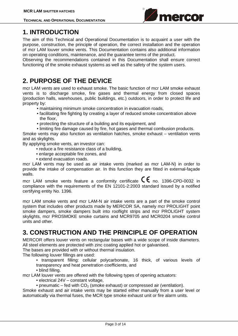
1. INTRODUCTION The aim of this Technical and Operational Documentation is to acquaint a user with the purpose, construction, the principle of operation, the correct installation and the operation of mcr LAM louver smoke vents. This Documentation contains also additional information on operating conditions, maintenance, and the guarantee terms of the product. Observing the recommendations contained in this Documentation shall ensure correct functioning of the smoke exhaust systems as well as the safety of the system users.
2. PURPOSE OF THE DEVICE mcr LAM vents are used to exhaust smoke. The basic function of mcr LAM smoke exhaust vents is to discharge smoke, fire gases and thermal energy from closed spaces (production halls, warehouses, public buildings, etc.) outdoors, in order to protect life and property by:
• maintaining minimum smoke concentration in evacuation roads, • facilitating fire fighting by creating a layer of reduced smoke concentration above
the floor, • protecting the structure of a building and its equipment, and • limiting fire damage caused by fire, hot gases and thermal combusion products.
Smoke vents may also function as ventilation hatches, smoke exhaust – ventilation vents and as skylights. By applying smoke vents, an investor can:
• reduce a fire resistance class of a building, • enlarge acceptable fire zones, and • extend evacuation roads.
mcr LAM vents may be used as air intake vents (marked as mcr LAM-N) in order to provide the intake of compensation air. In this function they are fitted in external-façade walls.
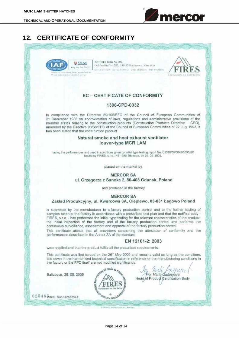
mcr LAM smoke vents feature a conformity certificate no. 1396-CPD-0032 in compliance with the requirements of the EN 12101-2:2003 standard issued by a notified certifying entity No. 1396. mcr LAM smoke vents and mcr LAM-N air intake vents are a part of the smoke control system that includes other products made by MERCOR SA, namely mcr PROLIGHT point smoke dampers, smoke dampers built into rooflight strips and mcr PROLIGHT system skylights, mcr PROSMOKE smoke curtains and MCR9705 and MCR0204 smoke control units and other.
3. CONSTRUCTION AND THE PRINCIPLE OF OPERATION MERCOR offers louver vents on rectangular bases with a wide scope of inside diameters. All steel elements are protected with zinc coating applied hot or galvanised. The bases are provided with or without thermal insulation. The following louver fillings are used:
• transparent filling: cellular polycarbonate, 16 thick, of various levels of transparency and heat penetration coefficients, and • blind filling.
mcr LAM louver vents are offered with the following types of opening actuators: • electrical 24V – constant voltage, • pneumatic – fed with CO2 (smoke exhaust) or compressed air (ventilation).
Smoke exhaust and air intake vents may be started either manually from a user level or automatically via thermal fuses, the MCR type smoke exhaust unit or fire alarm units.
MCR LAM SHUTTER HATCHES TECHNICAL AND OPERATIONAL DOCUMENTATION
Page 4 of 14
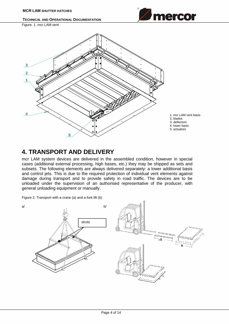
1. mcr LAM vent basis 2. blades 3. deflectors 4. lower basis 5. actuators
Figure. 1. mcr LAM vent
4
1
2
3
5
4. TRANSPORT AND DELIVERY mcr LAM system devices are delivered in the assembled condition, however in special cases (additional external processing, high bases, etc.) they may be shipped as sets and subsets. The following elements are always delivered separately: a lower additional basis and control jets. This is due to the required protection of individual vent elements against damage during transport and to provide safety in road traffic. The devices are to be unloaded under the supervision of an authorised representative of the producer, with general unloading equipment or manually. Figure 2. Transport with a crane (a) and a fork lift (b) a/ b/
struts
MCR LAM SHUTTER HATCHES TECHNICAL AND OPERATIONAL DOCUMENTATION
Page 5 of 14
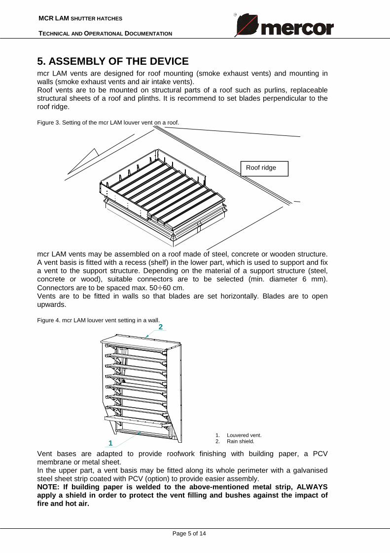
1. Louvered vent. 2. Rain shield.
5. ASSEMBLY OF THE DEVICE mcr LAM vents are designed for roof mounting (smoke exhaust vents) and mounting in walls (smoke exhaust vents and air intake vents). Roof vents are to be mounted on structural parts of a roof such as purlins, replaceable structural sheets of a roof and plinths. It is recommend to set blades perpendicular to the roof ridge. Figure 3. Setting of the mcr LAM louver vent on a roof.
Kalenica
mcr LAM vents may be assembled on a roof made of steel, concrete or wooden structure. A vent basis is fitted with a recess (shelf) in the lower part, which is used to support and fix a vent to the support structure. Depending on the material of a support structure (steel, concrete or wood), suitable connectors are to be selected (min. diameter 6 mm). Connectors are to be spaced max. 50÷60 cm. Vents are to be fitted in walls so that blades are set horizontally. Blades are to open upwards. Figure 4. mcr LAM louver vent setting in a wall.
2
1 Vent bases are adapted to provide roofwork finishing with building paper, a PCV membrane or metal sheet. In the upper part, a vent basis may be fitted along its whole perimeter with a galvanised steel sheet strip coated with PCV (option) to provide easier assembly. NOTE: If building paper is welded to the above-mentioned metal strip, ALWAYS apply a shield in order to protect the vent filling and bushes against the impact of fire and hot air.
Roof ridge
MCR LAM SHUTTER HATCHES TECHNICAL AND OPERATIONAL DOCUMENTATION
Page 6 of 14
1. mcr LAM vent basis 2. System panel
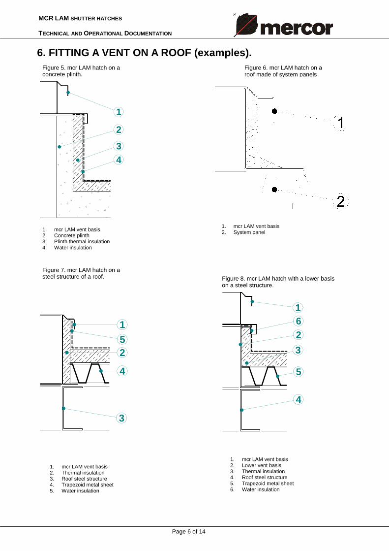
Figure 5. mcr LAM hatch on a concrete plinth.
Figure 6. mcr LAM hatch on a roof made of system panels
1. mcr LAM vent basis 2. Concrete plinth 3. Plinth thermal insulation 4. Water insulation
Figure 7. mcr LAM hatch on a steel structure of a roof.
1. mcr LAM vent basis 2. Thermal insulation 3. Roof steel structure 4. Trapezoid metal sheet 5. Water insulation
1. mcr LAM vent basis 2. Lower vent basis 3. Thermal insulation 4. Roof steel structure 5. Trapezoid metal sheet 6. Water insulation
6. FITTING A VENT ON A ROOF (examples).
1
2
34
1
25
4
3
1
2
3
5
4
6
Figure 8. mcr LAM hatch with a lower basis on a steel structure.
MCR LAM SHUTTER HATCHES TECHNICAL AND OPERATIONAL DOCUMENTATION
Page 7 of 14
b/ without any additional elements a/ directly, frontal
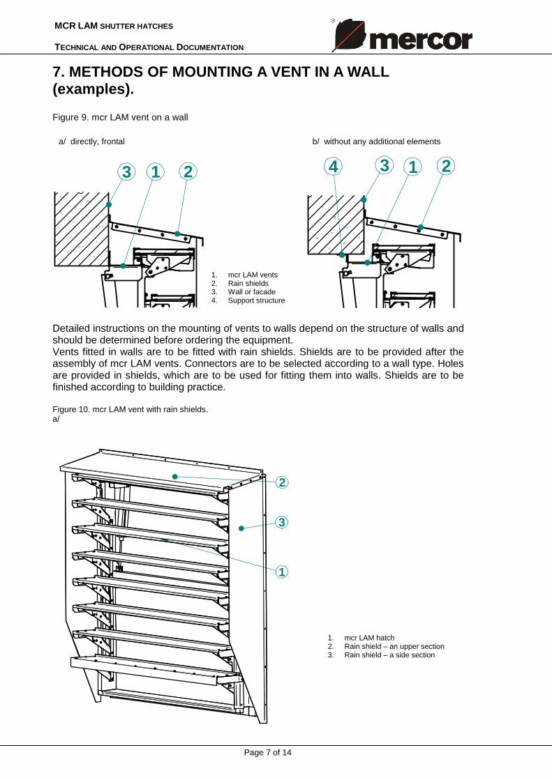
7. METHODS OF MOUNTING A VENT IN A WALL (examples). Figure 9. mcr LAM vent on a wall
3 21
3 214
Detailed instructions on the mounting of vents to walls depend on the structure of walls and should be determined before ordering the equipment. Vents fitted in walls are to be fitted with rain shields. Shields are to be provided after the assembly of mcr LAM vents. Connectors are to be selected according to a wall type. Holes are provided in shields, which are to be used for fitting them into walls. Shields are to be finished according to building practice. Figure 10. mcr LAM vent with rain shields. a/
2
3
1
1. mcr LAM vents 2. Rain shields 3. Wall or facade 4. Support structure
1. mcr LAM hatch 2. Rain shield – an upper section 3. Rain shield – a side section
MCR LAM SHUTTER HATCHES TECHNICAL AND OPERATIONAL DOCUMENTATION
Page 8 of 14
Figure 11. Control jet
b/
B
Sze
rokość
B + 350
A +
300
H+250
20050
25°
50
1
2
3
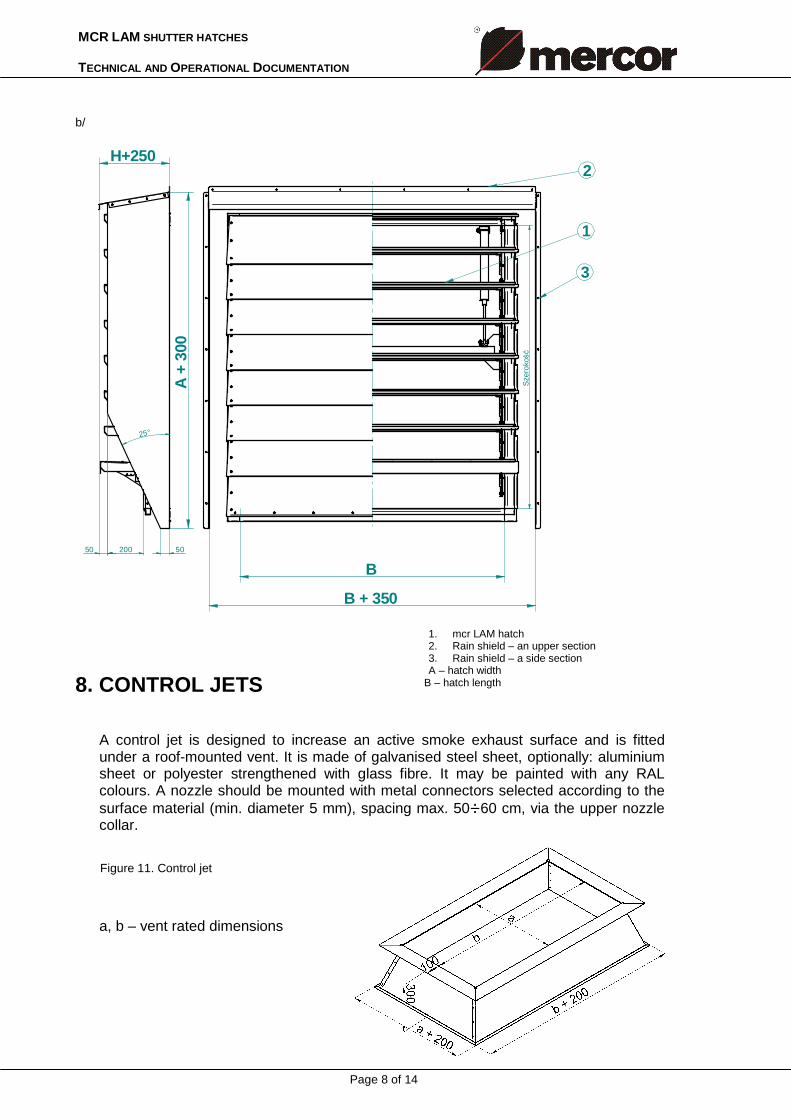
8. CONTROL JETS
A control jet is designed to increase an active smoke exhaust surface and is fitted under a roof-mounted vent. It is made of galvanised steel sheet, optionally: aluminium sheet or polyester strengthened with glass fibre. It may be painted with any RAL colours. A nozzle should be mounted with metal connectors selected according to the surface material (min. diameter 5 mm), spacing max. 50÷60 cm, via the upper nozzle collar.
a, b – vent rated dimensions
1. mcr LAM hatch 2. Rain shield – an upper section 3. Rain shield – a side section A – hatch width
B – hatch length
MCR LAM SHUTTER HATCHES TECHNICAL AND OPERATIONAL DOCUMENTATION
Page 9 of 14
9. CONTROL mcr LAM louver vents require devices that open and close them. Such appliances provide the smoke exhaust or smoke exhaust and ventilation control system. The smoke exhaust control system, depending on the application of the appliances, may be made as: • a pneumatic system, and • an electrical system,
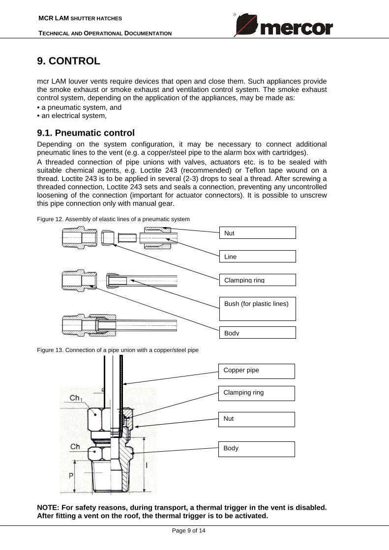
9.1. Pneumatic control Depending on the system configuration, it may be necessary to connect additional pneumatic lines to the vent (e.g. a copper/steel pipe to the alarm box with cartridges). A threaded connection of pipe unions with valves, actuators etc. is to be sealed with suitable chemical agents, e.g. Loctite 243 (recommended) or Teflon tape wound on a thread. Loctite 243 is to be applied in several (2-3) drops to seal a thread. After screwing a threaded connection, Loctite 243 sets and seals a connection, preventing any uncontrolled loosening of the connection (important for actuator connectors). It is possible to unscrew this pipe connection only with manual gear. Figure 12. Assembly of elastic lines of a pneumatic system
Figure 13. Connection of a pipe union with a copper/steel pipe
NOTE: For safety reasons, during transport, a thermal trigger in the vent is disabled. After fitting a vent on the roof, the thermal trigger is to be activated.
Nut
Line
Clamping ring
Bush (for plastic lines)
Body
Copper pipe
Clamping ring
Nut
Body
MCR LAM SHUTTER HATCHES TECHNICAL AND OPERATIONAL DOCUMENTATION
Page 10 of 14
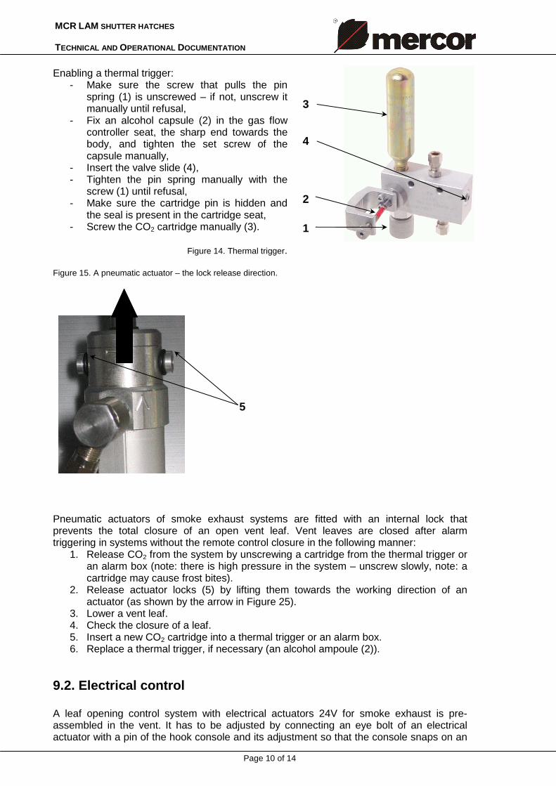
Enabling a thermal trigger:
- Make sure the screw that pulls the pin spring (1) is unscrewed – if not, unscrew it manually until refusal,
- Fix an alcohol capsule (2) in the gas flow controller seat, the sharp end towards the body, and tighten the set screw of the capsule manually,
- Insert the valve slide (4), - Tighten the pin spring manually with the
screw (1) until refusal, - Make sure the cartridge pin is hidden and
the seal is present in the cartridge seat, - Screw the CO2 cartridge manually (3).
Figure 14. Thermal trigger.
Figure 15. A pneumatic actuator – the lock release direction.
Pneumatic actuators of smoke exhaust systems are fitted with an internal lock that prevents the total closure of an open vent leaf. Vent leaves are closed after alarm triggering in systems without the remote control closure in the following manner:
1. Release CO2 from the system by unscrewing a cartridge from the thermal trigger or an alarm box (note: there is high pressure in the system – unscrew slowly, note: a cartridge may cause frost bites).
2. Release actuator locks (5) by lifting them towards the working direction of an actuator (as shown by the arrow in Figure 25).
3. Lower a vent leaf. 4. Check the closure of a leaf. 5. Insert a new CO2 cartridge into a thermal trigger or an alarm box. 6. Replace a thermal trigger, if necessary (an alcohol ampoule (2)).
9.2. Electrical control A leaf opening control system with electrical actuators 24V for smoke exhaust is pre-assembled in the vent. It has to be adjusted by connecting an eye bolt of an electrical actuator with a pin of the hook console and its adjustment so that the console snaps on an
5
3
1
2
4
MCR LAM SHUTTER HATCHES TECHNICAL AND OPERATIONAL DOCUMENTATION
Page 11 of 14
eye and the electrical actuator is switched off after closing a vent with a limit switch and not with an overload switch. The method of connecting an MCR-W actuator (conduit polarization): a brown conduit + a brown conduit –
a blue conduit – a blue conduit + MCR9705 and MCR0204 smoke exhaust and ventilation control systems as well as MCRR0424 and/or MCR0448 extending modules are to be used for controlling and supplying MCR-W electrical actuators of mcr LAM vents.
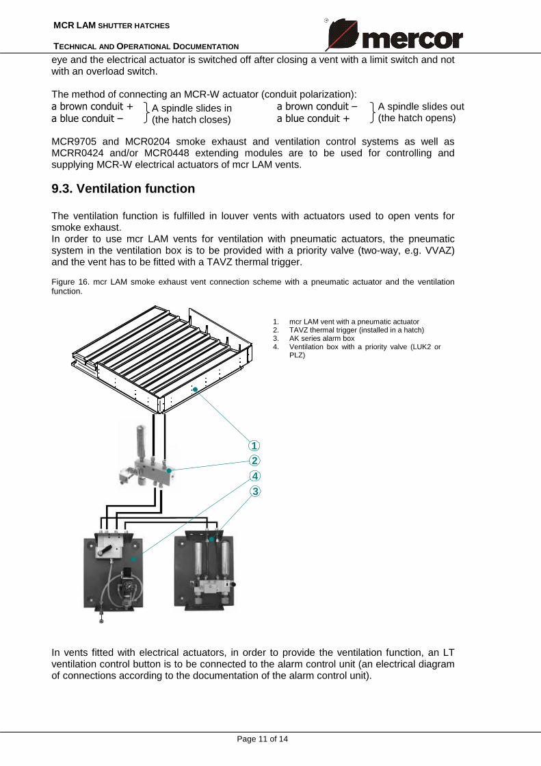
9.3. Ventilation function The ventilation function is fulfilled in louver vents with actuators used to open vents for smoke exhaust. In order to use mcr LAM vents for ventilation with pneumatic actuators, the pneumatic system in the ventilation box is to be provided with a priority valve (two-way, e.g. VVAZ) and the vent has to be fitted with a TAVZ thermal trigger. Figure 16. mcr LAM smoke exhaust vent connection scheme with a pneumatic actuator and the ventilation function.
3
21
4
In vents fitted with electrical actuators, in order to provide the ventilation function, an LT ventilation control button is to be connected to the alarm control unit (an electrical diagram of connections according to the documentation of the alarm control unit).
A spindle slides in (the hatch closes)
A spindle slides out (the hatch opens)
1. mcr LAM vent with a pneumatic actuator 2. TAVZ thermal trigger (installed in a hatch) 3. AK series alarm box 4. Ventilation box with a priority valve (LUK2 or
PLZ)
MCR LAM SHUTTER HATCHES TECHNICAL AND OPERATIONAL DOCUMENTATION
Page 12 of 14
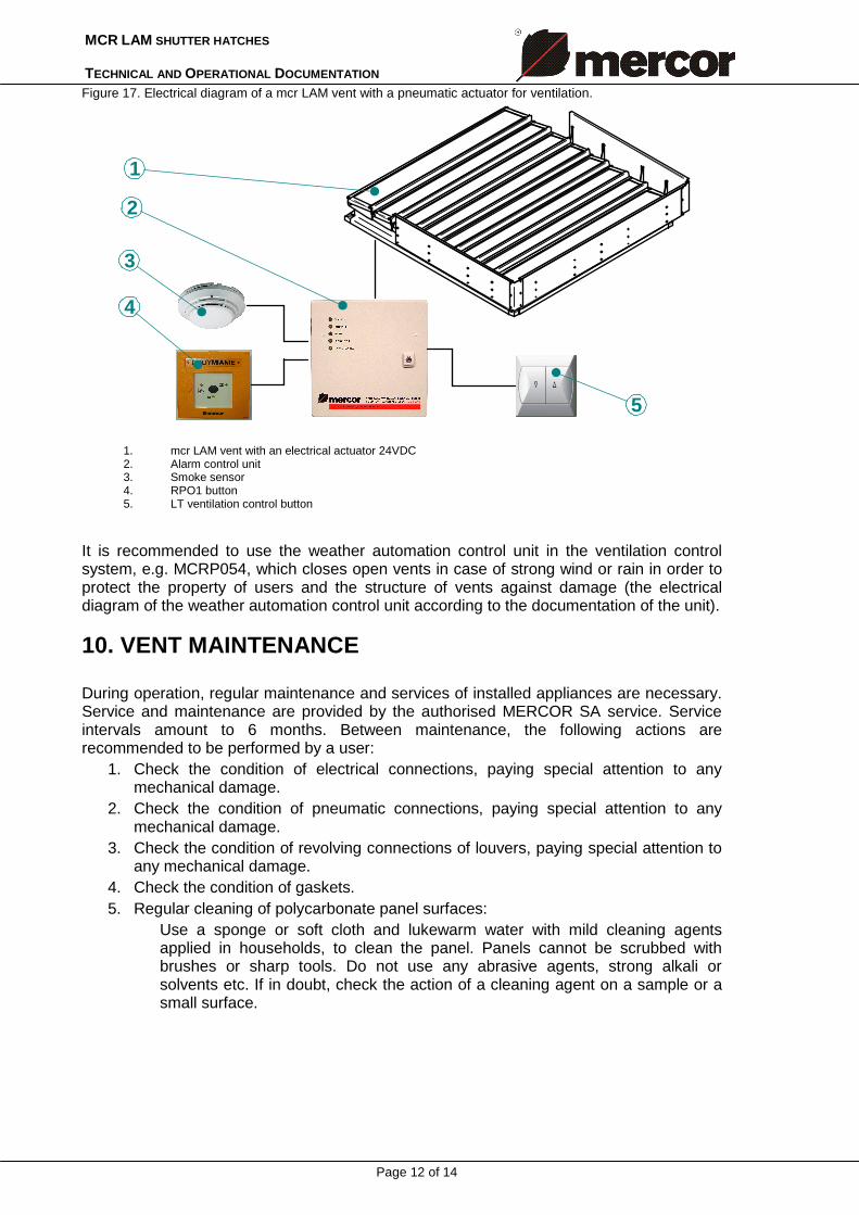
Figure 17. Electrical diagram of a mcr LAM vent with a pneumatic actuator for ventilation.
3
2
5
4
1
It is recommended to use the weather automation control unit in the ventilation control system, e.g. MCRP054, which closes open vents in case of strong wind or rain in order to protect the property of users and the structure of vents against damage (the electrical diagram of the weather automation control unit according to the documentation of the unit).
10. VENT MAINTENANCE During operation, regular maintenance and services of installed appliances are necessary. Service and maintenance are provided by the authorised MERCOR SA service. Service intervals amount to 6 months. Between maintenance, the following actions are recommended to be performed by a user:
1. Check the condition of electrical connections, paying special attention to any mechanical damage.
2. Check the condition of pneumatic connections, paying special attention to any mechanical damage.
3. Check the condition of revolving connections of louvers, paying special attention to any mechanical damage.
4. Check the condition of gaskets. 5. Regular cleaning of polycarbonate panel surfaces:
Use a sponge or soft cloth and lukewarm water with mild cleaning agents applied in households, to clean the panel. Panels cannot be scrubbed with brushes or sharp tools. Do not use any abrasive agents, strong alkali or solvents etc. If in doubt, check the action of a cleaning agent on a sample or a small surface.
1. mcr LAM vent with an electrical actuator 24VDC 2. Alarm control unit 3. Smoke sensor 4. RPO1 button 5. LT ventilation control button
MCR LAM SHUTTER HATCHES TECHNICAL AND OPERATIONAL DOCUMENTATION
Page 13 of 14
11. GUARANTEE AND SERVICE TERMS AND CONDITIONS 1. MERCOR SA provides a guarantee for the delivered product for 12 months since the date of purchase,
unless the contract specifies otherwise. 2. If any material defects are detected during the guarantee period, MERCOR SA undertakes to remedy them
within 21 days since the written notification, subject to Item 5 hereof. 3. In case of any defects that are caused by the improper operation of the equipment or for other reasons
specified in Item 6 below, a Buyer/a guarantee holder shall bear the costs of the repair. 4. The guarantee liability covers only defects that result from faults of the sold equpment. 5. MERCOR SA reserves the right to extend the repair period in case of complicated repairs or repairs that
require the procurement of non-standard subsystems (elements) or spare parts. 6. The guarantee does not cover:
• damage or failures of equipment due to incorrect operation, interference by a user, the lack of maintenance or regular services,
• damage of equipment for reasons other than caused by MERCOR S.A, in particular force majeure such as: stormy rain, flood, hurricane, lightning, short circuits, explosion, hail, fall of an aircraft, fire, avalanche, earth slide and secondary damage due to the above-mentioned causes. A stormy rain shall be the rain of the intensity of at least 4 as set by IMiGW (Institute of Meteorology and Water Management). If the intensity mentioned in the preceding sentence cannot be determined, the actual condition shall be taken into account as well as the scope of damage at the origin of such causes, which will constitute evidence of a stormy rain. A hurricane shall be the wind of the speed of at least 17.5m/2 (damage is considered to be caused by a hurricane, if the action of a hurricane has been confirmed in the vicinity);
• damage due to the failure to report a defect immediately; • deteriorated quality of coating due to natural wear (fading, oxidation); • defects due to the application of abrasive or aggressive cleaning agents; • parts that are subject to natural wear during operation (e.g. gaskets), unless a factory defect
occurs, and • damage caused by aggressive external factors, especially chemical and biological ones.
7. Any damage covered by the guarantee shall be reported to MERCOR SA immediately, i.e. within 7 days since its detection.
8. A buyer/a guarantee holder is obliged to operate, maintain and provide regular services (at least twice a year) of the equipment.
9. The guarantee expires immediately if: • a buyer/a guarantee holder modifies the structure without consultation with MERCOR SA, • maintenance or regular services are not performed in a timely manner or are performed by
unauthorised persons or a company not authorised by MERCOR SA or if equipment is not operated correctly, and
• an unauthorised person interferes with the equipment, other than for actions included in the normal operation of the equipment.
10. In situations mentioned in Item 9, the liability of MERCOR SA due to warranty is excluded. 11. Provisions of the Civil Code shall apply to any issues not governed herein.
Services 1. The equipment should undergo regular services, at least every 6 months during the whole period of its
operation (Article 3 of the Regulation by the Minister of Internal Affairs and Administration of 21 April 2006 on fire protection of buildings, structures and areas, Journal of Laws from 2006, No. 80, Item 563).
2. Services should be carried out by a company authorised by MERCOR SA (Article 3 of the Regulation by the Minister of Internal Affairs and Administration of 21 April 2006 on fire protection of buildings, structures and areas, Journal of Laws from 2006, No. 80, Item 563).
3. For services, please contact the Service Department at +48 58/ 341 42 45 ext. 173, 175 and 177, fax +48 58/ 341 39 85, from 8.00 a.m. to 4 p.m. (Mon-Fri).
MCR LAM SHUTTER HATCHES TECHNICAL AND OPERATIONAL DOCUMENTATION
Page 14 of 14
12. CERTIFICATE OF CONFORMITY