Embed Size (px)
Citation preview

Evaluates MAX30001MAX30001 Evaluation System
General DescriptionThe MAX30001 evaluation system (EV system) provides a single platform to evaluate the functionality and features of the MAX30001 with Biopotential (ECG, R-to-R, and Pace Detection) and Bioimpedance (BioZ) measurement capabilities. The EV system includes a MAX30001 evaluation kit (EV kit) and a MAX32630FTHR Cortex-M4F microcontroller for wearables. The MAX32630FTHR provides power to the MAX30001 EV kit and contains the firmware necessary to use the EV kit GUI program. The EV kit ships with jumpers installed and supply voltages set to typical operating values. Optional connections exist which can be shunted to make use of different functionalities.This EV system is not a medical device.
Features ● Convenient Platform to Evaluate the MAX30001 ● Many Easy-to-Reach Test Points ● Measure Individual Supply Currents ● Touchproof Cable Connectors ● Windows® 7/8/10 Compatible GUI software ● Fully Assembled and Tested ● Facilitates IEC 60601-2-47 Compliance Testing ● Ultra-Low-Power Design
EV System Contents ● MAX30001 EV kit ● MAX32630FTHR ● USB A to micro-USB cable ● Three (3) ECG cables
319-100083; Rev 0; 10/17
Ordering Information appears at end of data sheet.
Windows is a registered trademark and registered service mark of Microsoft Corporation.
MAX30001 EV Kit Photo

Maxim Integrated │ 2www.maximintegrated.com
Evaluates MAX30001MAX30001 Evaluation System
Quick StartRequired EquipmentNote: In the following sections, software-related items are identified by bold text. Text in bold refers to items directly from the install of EV kit software. Text which is bold and underlined refers to items from the Windows operating system.
● MAX30001 EV kit ● MAX32630FTHR ● Micro-USB cable ● Windows PC with USB port
ProcedureThe EV kit is fully assembled and tested. Follow the steps below to verify board operation:1) Confirm that the MAX32630FTHR is firmly seated in
connectors J8 and J7 in the proper orientation.2) Set the EV kit hardware on a nonconductive surface
to ensure that nothing on the PCB shorts together.3) Connect the EV kit hardware to a PC with the
provided USB cable. Attach the micro-USB end to the MAX32630FTHR board and the type A end to the host PC. Once connected, LED D1 on the MAX32630FTHR will blink red and LED D1 on the EV kit board will be green.
4) Windows should automatically begin installing the necessary device driver. The USB interface of the EV kit hardware is configured as an HID device and therefore does not require a unique/custom device driver. Once the driver installation is complete, a Windows message appears near the System Icon menu, indicating that the hardware is ready to use. Do not attempt to run the GUI prior to this message. If you do, then you must close the application and restart it once the driver installation is complete. On some versions of Windows, administrator privileges may be required to install the USB device.
5) Once the device drivers have been installed, down-load the latest EV kit software (MAX30001EVKitSoft-wareInstall.ZIP) and extract it to a temporary folder.
6) Open the extracted ZIP folder and double-click the .EXE file to run the installer. If a message box stating “The publisher could not be verified. Are you
sure you want to run this software?” appears, select the Yes option.
7) When the installer GUI appears, click Next. Select the installation paths and if a shortcut should be cre-ated on the desktop. When prompted, press Install. Once complete, click Close.
8) Double-click the shortcut to start the GUI. Alterna-tively, go to Start | All Programs. Look for the MAX-30001EVKitSoftware folder and click on the MAX-30001EVKitSoftware.EXE file inside the folder.
9) After the initial splash screen, when the GUI ap-pears, the text in the right field of the status strip at the bottom of the GUI window should display Hardware Connected and the COM port associated with the EV kit.
Detailed Description of SoftwareSoftware StartupIf the EV system is connected when the software is opened, the software first initializes the hardware to com-municate. The software then reads the device registers and updates all the associated control fields displayed on the GUI. The status strip at the bottom of the GUI displays MAX32630FTHR firmware version, the GUI version, and the hardware’s associated COM port.If the EV system is not connected on startup, the Connection Issue dialog box shown in Figure 1 appears after the GUI splash screen. Clicking OK opens the Connection window of the GUI. Use the Scan Ports but-ton to identify all COM ports in use by the PC and select the port associated with the EV kit hardware in the COM Port drop down menu. This window, shown in Figure 2, may appear if connecting to the EV kit for the first time even if the hardware is connected before starting the GUI.Once the correct COM port is selected, press Connect at the bottom center of the GUI to enter the main window. The program reads all device registers and updates the control fields of the GUI.
ToolStrip Menu BarThe ToolStrip menu bar (Figure 3) is located at the top of the GUI window. This bar comprises the File, Device, Options, Logging, and Help menus whose functions are detailed in the following sections.
MAX30001 Evaluation System FilesFILE DECRIPTION
MAX30001EVKit.exe PC GUI Program

Maxim Integrated │ 3www.maximintegrated.com
Evaluates MAX30001MAX30001 Evaluation System
Figure 1. The Connection Issue Dialog Box Appears If The GUI Does Not Detect the EV Kit.
Figure 2. The Connection Screen Allows The User to Select Which COM Port Contains the EV Kit.
Figure 3. The ToolStrip Menu Items.

Maxim Integrated │ 4www.maximintegrated.com
Evaluates MAX30001MAX30001 Evaluation System
File MenuThe File menu contains the option to exit out of the GUI program.
Device MenuThe Device menu provides the ability to connect or disconnect an EV system to the GUI. If a board is disconnected while the GUI is open the GUI will display Hardware Not Connected in the lower right corner. If the device is then plugged back in, the user will be able to navigate to the Device menu and select Connect. If successful, the bottom right corner of the GUI will read Device Connected and display the COM port to which the hardware is connected.
Options MenuThe Options menu provides several settings to access more features offered by the GUI. Show MAX30001 Register Names changes all the control field names to correspond with their register names in the data sheet. BioZ Milliohm Scale configures the scaling on the BioZ plot to be shown in milliohms rather than ohms for a zoomed in display of the BioZ measurement. Plots Maximum Time allows the user to select how many seconds of data they want to be shown on the plot at one time. The selected time will still show 10 divisions and each division will be 1/10 of the maximum time. By default, the maximum time is 10 seconds. Load Register Settings allows the user to quickly set up the GUI based on previous, saved register settings. The Save Register Settings item is used to save the current register settings in order to be loaded again at a later time. The Show Advanced Tab setting will add an extra tab in the GUI called Advanced. The advanced tab is described in depth in the Tab Control section of this document.
Logging MenuThe Logging menu provides a way to export accurate, exact data that is being measured by the device. The four log options are ECG File Log, R-To-R File Log, Pace File Log, and BioZ File Blog. Selecting any log option opens a prompt asking for a name for the comma-separated-value (CSV) log file, as well as the location to save the generated file. Figure 4 shows the GUI when creating a log file. Data logging begins when Start Monitor is pressed on the Plots tab and ends when Stop Monitor is pushed. The GUI disables logging after one monitoring session and a new file must be generated through the Logging menu to log the next dataset.
Help MenuThe Help menu contains information that can be helpful in aiding with any problems which may arise in the use of the GUI. Online Documentation takes the user to the Maxim Integrated website associated with the MAX30001 where all documents that are associated with the part are located. The About option displays the GUI splash screen which tells the user which GUI version is being used.
Tab ControlThe main interface structure of the GUI consists of a tab control, where each tab contains controls relevant to various blocks of the device. Changing these interactive controls triggers a write operation to the MAX30001 to update the register contents. Likewise, these controls are refreshed when reading from the device.Tabs responsible for configuring measurements contain block diagrams of their respective channel. To configure a measurement channel, select the desired values from the drop down list items in and below the diagram. Switches in the block diagrams open and close according to the device configuration.

Maxim Integrated │ 5www.maximintegrated.com
Evaluates MAX30001MAX30001 Evaluation System
Figure 4. Saving a Log File.

Maxim Integrated │ 6www.maximintegrated.com
Evaluates MAX30001MAX30001 Evaluation System
Home TabThe Home tab (Figure 5) provides an overview of the MAX30001 EV kit’s features and preset register configurations. Teal text in the MAX30001 block diagram links to that functional block’s tab in the GUI.Below the block diagram are six Quick Start Settings that configure the device’s registers according to the Quick Start Settings description. To load a Quick Start Setting, click on the desired setting in the left box and click on Apply Settings. The MAX30001 will be written with the specified configuration. These presets allow users to quickly verify the functionality of the EV kit. A button labeled “Go To Plot Tab” will change the GUI to the Plots tab where a live graph of data being measured can be initiated by clicking the “Start Monitor” button.
Figure 5: MAX30001 EV Kit GUI Home Tab

Maxim Integrated │ 7www.maximintegrated.com
Evaluates MAX30001MAX30001 Evaluation System
ECG Channel TabThe ECG Channel tab (Figure 6) contains all settings which dictate the signal processing behavior of the ECG measurement channel. Controls for the ECG input channel, such as Fast Recovery settings, gain for the programmable amplifier, and the ADC sampling rate, are found in the ECG Channel block diagram. The R-to-R box configures R-to-R detection using the ECG input data.A detailed description of all ECG channel configuration settings and R-to-R functionality can be found in the MAX30001 data sheet.
Figure 6: ECG Channel Tab.

Maxim Integrated │ 8www.maximintegrated.com
Evaluates MAX30001MAX30001 Evaluation System
ECG MUX TabThe ECG MUX tab (Figure 7) configures the internal ECG switches that precede the ECG amplifiers and filters. Internal calibration and verification functions of the IC are also accessible from this tab. In order to measure external ECG signals, the ECGP Switch and ECGN Switch in the Switches block must be set to Connected. The switches should be set to Isolated if Calibration Test Voltage is used. It is also recommended to have Resistive Lead Bias Enable set to ECG Bias, Resistive Bias Value set to 100MΩ, Positive Input Bias Enable and Negative Input Bias Enable set to Connected. DC Lead-Off Check, ULP Lead-On Check, and Calibration Test Voltage functionalities are detailed further in depth in the MAX30001 data sheet.
Figure 7: ECG MUX Tab

Maxim Integrated │ 9www.maximintegrated.com
Evaluates MAX30001MAX30001 Evaluation System
BioZ Channel TabThe BioZ Channel tab (Figure 8) hosts the settings that control the BioZ components following the BioZ Input MUX. As in the ECG Channel tab, controls on this tab configure the filters and amplifiers of the device’s BioZ channel.A detailed description of all BioZ channel configuration settings can be found in the MAX30001 data sheet.
Figure 8: BioZ Channel Tab.

Maxim Integrated │ 10www.maximintegrated.com
Evaluates MAX30001MAX30001 Evaluation System
BioZ MUX TabThe BioZ MUX tab (Figure 9) configures the internal BioZ switches that precede the BioZ signal path. Internal calibration and verification functions of the IC are also accessible from this tab. In order to use the BioZ channel, the BIP Switch and BIN Switch in the Switches block must be set to Connected. The switches should be set to Isolated if using the internal self-test features. As part of the BioZ self-test, a resistive load is available on the DRVP and DRVN pins. Clicking on Selectable Resistive Load will bring the GUI to the BioZ Load tab. Refer to the full MAX30001 data sheet for detailed descriptions of the BioZ MUX configurations.
Figure 9: BioZ MUX Tab.

Maxim Integrated │ 11www.maximintegrated.com
Evaluates MAX30001MAX30001 Evaluation System
BioZ LoadThe BioZ Load tab (Figure 10) configures the resistive load used for the self-test of the BioZ channel. The nominal resistance and modulation frequency are set by the Nominal Resistance and Frequency controls in the Modulated Resistance Built-In-Self-Test (RMOD BIST) block. RMOD BIST Enable configures the BioZ channel to connect or detach the resistive load.Refer to the full IC data sheet for a description of the modulated resistive load.
Figure 10: BioZ Load Tab.

Maxim Integrated │ 12www.maximintegrated.com
Evaluates MAX30001MAX30001 Evaluation System
Pace Channel TabThe Pace Channel tab (Figure 11) configures the input channel for pace detection. In addition to setting the channel gain and detection thresholds, this tab can route signals at various points in the input path to AOUT using the Signal Selection control. To enable pace detection, BIP Switch and BIN Switch in the BioZ MUX tab must be set to Connected. If using the current generator to measure BioZ and pace simultaneously, the frequency must be 40kHz or 80kHz.
Figure 11: Pace Channel Tab.

Maxim Integrated │ 13www.maximintegrated.com
Evaluates MAX30001MAX30001 Evaluation System
Plots TabThe Plots tab (Figure 12) enables real time monitoring of ECG and BioZ waveforms. By default, both ECG and BioZ plots are visible. Toggling the controls in Channel/Plot Enable changes which of the two plots is displayed. If ECG is enabled and BioZ is disabled, the plot area will be occupied entirely by the ECG waveform. Likewise, if BioZ is enabled instead of ECG, the BioZ plot is maximized. When both measurement channels are enabled, the plotting space contains both ECG and BioZ data.
Figure 12: Plots Tab.

Maxim Integrated │ 14www.maximintegrated.com
Evaluates MAX30001MAX30001 Evaluation System
R-to-R and Pace data is shown in the ECG plot. R-to-R peak detection is indicated by a red circle at the peaks of the R waves. Pace data appears as teal arrows on the rising and falling slopes of the pace signal. Heart rate information gathered from R-to-R detection can be found in the Heart Rate (from R-to-R) box below the plotting area. Figure 13 illustrates an ECG waveform with R-to-R and pace detection enabled. The ECG sample rate is 512sps and the BioZ current generator frequency is 80kHz.
Figure 13. An ECG Waveform with R-to-R and Pace Detection Enabled.

Maxim Integrated │ 15www.maximintegrated.com
Evaluates MAX30001MAX30001 Evaluation System
MicroSD Log TabThe MAX30001 EV kit can use the SD card read/write functionality of the MAX32630FTHR to store and recall log data to and from a microSD card. This allows data to be with the USB cable connected or with the USB discon-nected from the PC host and powering the EV kit with a battery. To use an SD card, insert the card into connector CN2 on the underside of the MAX32630FTHR board prior to starting the GUI.SD card logging is configured in the MicroSD Log tab (Figure 14). The GUI can save, load, and clear stored register configuration settings with the Read, Write, and
Erase buttons, respectively. Pressing Advanced displays the current register contents to be written to an SD card setting file when Write is pressed. After confirming the register configurations, select the type of data to save in the ECG Channel Log Enable box and press Write to load the measurement parameters to the SD card. Press SW2 on the MAX32630FTHR board to start logging and press it a second time to stop logging.When the EV kit is reconnected to the GUI after logging data, data from the SD card can be saved to the host PC. Press Save to File to open a file dialogue and select the location and file name of the logged data. Data is stored in a CSV format.
Figure 14: MicroSD Log Tab with Advanced Toggled On.

Maxim Integrated │ 16www.maximintegrated.com
Evaluates MAX30001MAX30001 Evaluation System
Registers TabThe Registers tab (Figure 15) provides more direct access to the internal registers of the MAX30001. From this tab, it is possible to read the contents of individual registers and to manually enter the desired bit settings for a write operation. For the register address selected in the table on the left, the contents are displayed at the bottom of the tab and visualized as bold and non-bold bit names. When a bit is bold, its value is 1. Otherwise, the bit is 0. Full descriptions of each bit are available in the Bit Description field for quick reference. Pressing Read reads the selected register, highlighted in teal, while pressing Read All reads all registers and updates their values in the Registers tab. To write to a register, set the desired bit values by clicking on the bit names to make bold or non-bold and then press Write. Alternatively, double click the Value (Hex) cell of a selected row to manually enter a value and press the “Enter” key to write the value to the device register.
Figure 15: Registers Tab.

Maxim Integrated │ 17www.maximintegrated.com
Evaluates MAX30001MAX30001 Evaluation System
Advanced TabThe Advanced tab (Figure 16) is accessible through the Options ToolStrip menu. The tab provides manual communication with the MAX30001 to bypass the GUI controls entirely. Enter the register address, as a hexadecimal value, in the Address field. Read data from a register by pressing the ReadReg button and the data will populate the Read Data field. To write data, enter the hexadecimal value in the Write Data field and press the WriteReg button. Command Line displays the formatted command sent by the GUI to the EV kit.
Figure 16: Advanced Tab.

Maxim Integrated │ 18www.maximintegrated.com
Evaluates MAX30001MAX30001 Evaluation System
Detailed Description of HardwareThe MAX30001 EV system provides a single platform to evaluate the functionality and features of the MAX30001 with Biopotential (ECG, R-to-R, and Pace Detection) and Bioimpedance (BioZ) measurement capabilities. The board contains jumpers and optional resistors and capacitors to test the MAX30001 under several conditions. A list of all jumpers and their respective functions is available in Table 1. An onboard 32.768kHz crystal oscillator (U5) supplies FCLK to the IC, but external frequency generation is supported.
The EV system utilizes the MAX32630FTHR Cortex-M4F Microcontroller for Wearables for interfacing with the GUI and optionally providing power to the MAX30001. The MAX32630FTHR operates either from a host PC or directly from a Li+ battery. If an SD card is present in the MAX32630FTHR, register settings and measurement configurations can be saved through the GUI. When the EV kit operates without a host PC, pressing SW2 on the MAX32630FTHR initiates the measurement and saves log files to the SD card. Logging is stoped by pressing SW2 a second time.Refer to Figure 17 for a simplified schematic of the EV kit biopotential circuitry.
Table 1. Description Of JumpersJUMPER SHUNT POSITION DESCRIPTION
J_ECGN 1-2* Connects ECGN on the IC to C_ECGN on the EV kit.
J_ECGP 1-2* Connects ECGP on the IC to C_ECGP on the EV kit.
EN_BN 1-2 Connects ECGN to BIN.
EP_BP 1-2 Connects ECGP to BIP.
EN_UNBAL 1-2* Bypasses the ECG electrode unbalance on ECGN.
EP_UNBAL 1-2* Bypasses the ECG electrode unbalance on ECGP.
EP_EN 1-2 Short ECGP to ECGN.
J_BIN 1-2* Connects BIN on the IC to C_BIN on the EV kit.
J_BIP 1-2* Connects BIN on the IC to C_BIN on the EV kit.
RN 1-2* Connects one end of R28 to BIN.
RP 1-2* Connects one end of R28 to BIP.
DN_BN 1-2 Connects DRVN to BIN.
DP_BP 1-2 Connects DRVP to BIP.
BP_BN 1-2 Short BIP to BIN.
J_DRVN 1-2 Connects DRVN on the IC to C_DRVN on the EV kit.
J_DRVP 1-2 Connects DRVP on the IC to C_DRVP on the EV kit.
BB_SEL1-2* Use VCM as the body bias.
2-3 Use an adjustable voltage from 0V to OVDD as the body bias. Adjust voltage with R7.
J_RBIAS 1-2* Connect an external 324kΩ resistor to RBIAS.
BUFF1_IN 1-2 Input to second buffer of U4.

Maxim Integrated │ 19www.maximintegrated.com
Evaluates MAX30001MAX30001 Evaluation System
Table 1. Description Of Jumpers (continued)
* Default shunt position ** Default shunt position, do not use alternate position
JUMPER SHUNT POSITION DESCRIPTION
1V81-2 Supply 1.8V to J_AVDD and J_DVDD from the MAX32630FTHR.
2-3* Supply an adjustable voltage to J_AVDD and J_DVDD from an LDO (U2).
3V31-2 Supply 3.3V to J_OVDD and OVDDX from the MAX32630FTHR.
2-3* Supply an adjustable voltage to J_OVDD and OVDDX from an LDO (U3).
J_AVDD 1-2* Connect AVDD to pin 2 of jumper 1V8.
J_DVDD 1-2* Connect DVDD to pin 2 of Jumper 1V8.
J_OVDD 1-2* Connect OVDD to pin 2 of jumper 3V3.
XTL_PWR 1-2* Power the onboard crystal from OVDDX.
ONBRD_FCLK 1-2* Connect the onboard crystal to FCLK.
GND1 1-2** Connect GND of the MAX32630FTHR to AGND1.
GND2 1-2** Connect GND of the MAX32630FTHR to AGND2.
J_EXT_PWR1-2 Connect an external supply to the 5V rail.
2-3 Do not use.
J_SYS 1-2** Connect SYS on the MAX32630FTHR to the 5V rail.
J_INTB 1-2** Connect INTB to the MAX32630FTHR.
J_INT2B 1-2** Connect INT2B to the MAX32630FTHR.
J_SDO 1-2** Connect SDO to MISO of the MAX32630FTHR.
J_SDI 1-2** Connect SDI to MOSI of the MAX32630FTHR.
J_SCLK 1-2** Connect SCLK to SCLK of the MAX32630FTHR.
J_CSB 1-2** Connect CSB to the MAX32630FTHR.
P_UP 1-2 Connect R8-11 to OVDDX.
P_DWN 1-2* Connect R15-17 to GND.

Maxim Integrated │ 20www.maximintegrated.com
Evaluates MAX30001MAX30001 Evaluation System
Figure 17. Simplified Schematic.
10kΩ10kΩ
10kΩBB
MAX30001
VCM
OVDDX
DNI
DNI DNI
1x
EP_EN
0Ω
DNI
DNI DNI
BP_BN
0Ω
EN_UNBAL
EP_UNBAL
RP
RN
EP_B
P
EN_B
N
DP_B
P
DN_B
N
J_ECGP
J_DRVP
J_ECGN
J_BIP
J_BIN
J_DRVN
BB_SEL
DRVN
DRVP
BIN
BIP
ECGN
ECGP
DRVN
DRVP
BIN
BIP
ECGN
ECGP
MAX32630FTHR
INT2B
INT2BAVDD
AVDD
OVDD
DVDD
J_AVDD
J_DVDD
J_OVDD
DVDD OVDD
100Ω
SPI
4
INTB
INTBSPI
0Ω
0Ω
47nF
47nF

Maxim Integrated │ 21www.maximintegrated.com
Evaluates MAX30001MAX30001 Evaluation System
Powering the EV KitThe MAX30001 EV kit can be powered from an external supply or directly from the MAX32630FTHR. To use an external supply, install a shunt on jumper J_EXT_PWR in the 1-2 position. This connects the EXT_PWR test point to the board’s 5V rail. Set the power supply’s output to +5V, disable the output, connect the positive lead to EXT_PWR and the negative to AGND1, then enable the supply. To power the EV kit with the MAX32630FTHR, install a shunt on jumper J_SYS in the 1-2 position to connect the SYS node to the 5V rail. SYS regulates the USB voltage or directly connects to the battery if present.The MAX30001 IC receives power from OVDD, AVDD, and DVDD. These pins receive power either through the MAX32630FTHR, externally through test points, or through adjustable LDOs U2 and U3. To supply the IC from the MAX32630FTHR’s 1.8V and 3.3V rails, place a shunt in the 1-2 position on the 1V8 and 3V3 jumpers. To use the onboard LDOs, place the shunts in the 2-3 position. Two potentiometers are available to set the U2 and U3 voltages: R4 and R10.To operate the EV kit without a connection to a host PC or power supply, insert a microSD card into the MAX32630FTHR. After saving a test configuration, disconnect the board from the host PC and connect a Li+ battery to the MAX32630FTHR. Refer to the MAX32630FTHR documentation for details on connecting a Li+ battery. Press SW2 to trigger the measurements saved to the SD card. The J_SYS shunt must be in the 1-2 position for this configuration.
Configuring the Board for MeasurementThe MAX30001 EV kit offers several potential connection and component configurations to enable a variety of tests. Both the ECG channel and BioZ channel allow for user-defined line resistance with resistors R26 and R27 for BioZ, and R29 and R30 for ECG. By default, these resistors are populated with 0Ω shunts but can be changed to suit the application. The board also allows for the installation of external low-pass filtering capacitors on the ECG and BioZ lines. Capacitors C8 and C25 can create an external common mode filter for the ECG and BioZ lines, respectively. C24, C29, C26, and C28 filter ECGP, ECGN, BIP, and BIN. The cutoff frequency of the filters is set by the value of these capacitors and the input resistors R26, R27, R29, and R30. The board also allows the ECGN and ECGP or BIN and BIP inputs to be shorted with jumpers EP_EN and BP_BN, respectively.Refer to the MAX30001 EV kit schematic and MAX30001 EV kit PCB layout sections for component connections and placements.
ECG MeasurementThe EV kit ships configured to measure ECG with balanced electrodes, R-to-R, and BioZ signals. The jumper configurations required for these measurements are shown in Figure 18. Connected jumpers are distinguished with solid black nodes in the jumper box. To use the electrode connectors on the EV kit, ensure the required shunts are installed.By default, the EV kit leaves the ECG channel balanced. By removing the shunts on EN_UNBAL And EP_UNBAL, the ECGN and ECGP lines each include a 51kΩ resistor and 47nF capacitor in parallel.

Maxim Integrated │ 22www.maximintegrated.com
Evaluates MAX30001MAX30001 Evaluation System
BioZ MeasurementAdditionally, the EV kit includes a 100Ω resistor to verify the BioZ configuration. Attach shunts on RP and RN to connect the resistor to the BioZ inputs and shunts on DP_BP and DN_BN to route the drive signal to the BioZ channel. Figure 19 illustrates these connections.Refer to the MAX30001 data sheet for details on configuring a BioZ measurement. Note that the default setting of the current generator is FMSTR/64 (about 500Hz) and the BioZ channel has an internal high-pass filter with a default 1kHz cutoff frequency. In order to correctly measure the 100Ω resistor, bypass or lower the filter cutoff frequency or increase the current generator frequency.
Pace DetectionTo enable pace detection, the ECGN and ECGP lines must be connected to BIN and BIP by shunting EN_BN and EP_BP, then configuring the device registers as described in the IC datasheet. Refer to Figure 20 for a jumper configuration to measure ECG with pace detection.Alternatively, EP_BP and EN_BN can be left open and J_BIP and J_BIN shunted. This measures pace directly on the BIP and BIN inputs and allows another signal to be measured on the ECG channel. In this configuration, the measured pace signal may not correspond to the ECG measurement.
Figure 18. Default Measurement Channel Jumper Configurations
EP_EN
0Ω
BP_BN
0Ω
EN_UNBAL
EP_UNBAL
RP
RN
EP_BP EN_BN
J_ECGP
J_DRVP
J_ECGN
J_BIP
J_BIN
J_DRVN
47nF
47nF
DRVN
DRVP
BIN
BIP
ECGN
ECGP
DRVN
DRVP
BIN
BIP
ECGN
ECGP
100Ω
DP_BP DN_BN
0Ω
0Ω

Maxim Integrated │ 23www.maximintegrated.com
Evaluates MAX30001MAX30001 Evaluation System
Figure 19. BioZ Measurement with 100Ω Test Impedance.
Figure 20. Configuring the EV Kit to Detect Pace Signals.
EP_EN
BP_BN
EN_UNBAL
EP_UNBAL
RP
RN
EP_BP EN_BN
DP_BP DN_BN
J_ECGP
J_DRVP
J_ECGN
J_BIP
J_BIN
J_DRVN
47nF
47nF
DRVN
DRVP
BIN
BIP
ECGN
ECGP
DRVN
DRVP
BIN
BIP
ECGN
ECGP
100Ω
0Ω
0Ω
0Ω
0Ω
EP_EN
EN_UNBAL
EP_UNBAL
EP_BP EN_BN
DP_BP DN_BN
J_ECGP
J_DRVP
J_ECGN
J_DRVN
47nF
47nF
DRVN
DRVP
ECGN
ECGP
DRVN
DRVP
ECGN
ECGP
BP_BN
RP
RN
J_BIP
J_BIN
BIN
BIP
BIN
BIP
100Ω
0Ω
0Ω
0Ω
0Ω

Maxim Integrated │ 24www.maximintegrated.com
Evaluates MAX30001MAX30001 Evaluation System
Note: Indicate that you are using the MAX30001 EV kit when contacting these component suppliers.
SUPPLIER WEBSITEBourns www.bourns.com
Epson www.epson.com
Kemet www.kemet.com
Keystone www.keyelco.com
Lite-On Electronics us.liteon.com
Maxim Integrated www.maximintegrated.com
Murata www.murata.com
Panasonic www.panasonic.com
Plastics One www.plasticsone.com
Sullins Connector Solutions www.sullinscorp.com
Susuma www.susuma-usa.com
Taiyo Yuden www.t-yuden.com
TDK www.global.tdk.com
TE Connectivity www.te.com
Vishay Dale www.vishay.com
PART TYPEMAX30001EVSYS# EV System
Component Suppliers
Ordering Information

Maxim Integrated │ 25www.maximintegrated.com
Evaluates MAX30001MAX30001 Evaluation System
MAX30001 EV Kit Bill of Materials (BOM) ITEM REF_DES DNI/DNP QTY MFG PART # MANUFACTURER VALUE DESCRIPTION
11V8, 3V3, GND1, GND2, J_CSB, J_SDI, J_SDO, J_SYS, BB_SEL,
J_INTB, J_SCLK, J_INT2B, J_EXT_PWR- 13 PCC03SAAN SULLINS PCC03SAAN CONNECTOR; MALE; THROUGH HOLE; BREAKAWAY;
STRAIGHT THROUGH; 3PINS; -65 DEGC TO +125 DEGC
2
BB, BIN, BIP, CSB, SDI, SDO, VBG, VCM, AGND, AOUT, DRVN, DRVP, ECGN, ECGP, FCLK, INTB, SCLK, VREF, AGND1-AGND4, INT2B, RBIAS, FTHR_GND, BUFF1_OUT
- 26 5011 KEYSTONE N/ATEST POINT; PIN DIA=0.125IN; TOTAL LENGTH=0.445IN; BOARD HOLE=0.063IN; BLACK; PHOSPHOR BRONZE WIRE SILVER PLATE FINISH;
3 AVDD, DVDD, OVDD, EXT_PWR - 4 5010 KEYSTONE N/A TESTPOINT WITH 1.80MM HOLE DIA, RED, MULTIPURPOSE;
4
RN, RP, P_UP, BP_BN, DN_BN, DP_BP, EN_BN, EP_BP, EP_EN, J_BIN, J_BIP, J_AVDD, J_DRVN, J_DRVP, J_DVDD, J_ECGN, J_ECGP, J_OVDD,
P_DOWN, J_RBIAS, XTL_PWR, BUFF1_IN, EN_UNBAL, EP_UNBAL, ONBRD_FCLK
- 25 5-146280-2 TE CONNECTIVITY 5-146280-2CONNECTOR; MALE; THROUGH HOLE; HEADER ASSEMBLY; MOD II; BREAKWAY; SINGLE ROW; HIGH TEMPERATURE; VERTICAL W/ 0.025 SQ POST; 0.100 C; STRAIGHT; 2PINS
5 C1-C3, C30 - 4 C0805C473J3GAC KEMET 0.047UF CAPACITOR; SMT (0805); CERAMIC CHIP; 0.047UF; 25V; TOL=5%; TG=-55 DEGC TO +125 DEGC; TC=C0G
6 C4 - 1 UMK107AB7105KA TAIYO YUDEN 1UF CAPACITOR; SMT (0603); CERAMIC CHIP; 1UF; 50V; TOL=10%; TG=-55 DEGC TO +125 DEGC; TC=X7R
7 C5-C7, C16-C21, C23 - 10 GRM188R61E106MA73 MURATA 10UF CAPACITOR; SMT (0603); CERAMIC CHIP; 10UF; 25V; TOL=20%; TG=-55 DEGC TO +85 DEGC; TC=X5R; GRM SERIES; MURATA
8 C9, C10, C14, C15 - 4 C3216X7R1H335M160AC TDK 3.3UF CAPACITOR; SMT (1206); CERAMIC CHIP; 3.3UF; 50V; TOL=20%; MODEL=C SERIES; TG=-55 DEGC TO +125 DEGC; TC=X7R
9 C11-C13, C22 - 4 C1608X7R1E104K080AA TDK 0.1UF CAPACITOR; SMT (0603); CERAMIC CHIP; 0.1UF; 25V; TOL=10%; MODEL=C SERIES; TG=-55 DEGC TO +125 DEGC; TC=X7R
10 C27, C31 - 2 GRM31CR72A225KA73;KRM31KR72A225KH01 MURATA 2.2UF CAPACITOR; SMT (1206); CERAMIC CHIP; 2.2UF; 100V;
TOL=10%; MODEL=GRM SERIES; TG=-55 DEGC TO +125 DEGC; TC=X7R
11 C32 - 1 C0603C102J5GAC; 06035A102JAT2A KEMET/AVX/MURATA 1000PF CAPACITOR; SMT; 0603; CERAMIC; 1000pF; 50V; 5%; C0G; -55degC to +125degC
12 C_BB, C_BIN, C_BIP, C_DRVN, C_DRVP, C_ECGN, C_ECGP - 7 41828-50 PLASTICS ONE 41828-50 CONNECTOR; FEMALE; THROUGH HOLE; JACK; PCB; 1.5MM;
TOUCHPROOF WAVE SOLDER VERSION WITH STAMPING; RIGHT ANGLE; 3PINS
13 D1 - 1 LTST-C194KGKT LITE-ON ELECTRONICS INC LTST-C194KGKT DIODE; LED; SMD CHIP LED; WATER CLEAR LENS; AlInGaP GREEN; GREEN; SMT (0603); VF=2.1V; IF=0.02A
14 J8 - 1 PPPC161LFBN-RC SULLINS ELECTRONICS CORP. PPPC161LFBN-RC CONNECTOR; FEMALE; THROUGH HOLE; LFB SERIES; 2.54MM CONTACT CENTER; STRAIGHT; 16PINS
15 J9 - 1 PPPC121LFBN-RC SULLINS ELECTRONICS CORP PPPC121LFBN-RC CONNECTOR; FEMALE; THROUGH HOLE; HEADER FEMALE; STRAIGHT; 12PINS
16 R1, R31 - 2 ERA-6ARW513 PANASONIC 51K RESISTOR; 0805; 51K OHM; 0.05%; 10PPM; 0.125W; THIN FILM17 R2, R3 - 2 CRCW06031001FK; ERJ-3EKF1001V VISHAY DALE; PANASONIC 1K RESISTOR; 0603; 1K; 1%; 100PPM; 0.10W; THICK FILM
18 R4, R10 - 2 3296Y-202LF BOURNS 2K RESISTOR; THROUGH HOLE-RADIAL LEAD; 3296Y SERIES; 2K OHM; 10%; 100PPM; 0.5W
19 R5, R6 - 2 CRCW06031K33FK VISHAY DALE 1.33K RESISTOR; 0603; 1.33K; 1%; 100PPM; 0.10W; THICK FILM
20 R7 - 1 3296Y-1-103LF BOURNS 10K RESISTOR; THROUGH-HOLE; 10K OHM; 10%; 100PPM; 0.5W; MOLDER CERAMIC OVER METAL FILM
21 R9, R11, R36 - 3 CRCW06031003FK; ERJ-3EKF1003 VISHAY DALE/PANASONIC 100K RESISTOR; 0603; 100K; 1%; 100PPM; 0.10W; THICK FILM22 R12 - 1 RN73C1J324KB; 4-1879135-8 TE CONNECTIVITY 324K RESISTOR; 0603; 324K OHM; 0.1%; 10PPM; 0.063W; THIN FILM23 R13, R18, R19, R28 - 4 RG1608P-101-B-T5; ERA-3YEB101V SUSUMU CO LTD./PANASONIC 100 RESISTOR; 0603; 100 OHM; 0.1%; 25PPM; 0.1W; THICK FILM24 R14 - 1 RG1608P-471-B-T5 SUSUMU CO LTD. 470 RESISTOR; 0603; 470 OHM; 0.1%; 25PPM; 0.10W; THICK FILM25 R20, R25 - 2 ERA-3ARB103 PANASONIC 10K RESISTOR; 0603; 10K OHM; 0.1%; 10PPM; 0.1W; THIN FILM
26 R26, R27, R29, R30 - 4 CRCW06030000ZS; MCR03EZPJ000; ERJ-3GEY0R00
VISHAY DALE/ROHM/PANASONIC 0 RESISTOR; 0603; 0 OHM; 0%; JUMPER; 0.10W; THICK FILM
27 U1 - 1 MAX30001CWV+ MAXIM MAX30001CWV+
EVKIT PART-IC; MAX30001; ULTRA-LOW POWER; SINGLE-CHANNEL INTEGRATED BIOPOTENTIAL AND BIOIMPEDANCE AFE; PACKAGE OUTLINE: 21-100074; PACKAGE CODE: W302L2+1; WLP30
28 U2 - 1 MAX1806EUA18+ MAXIM MAX1806EUA18+ IC; VREG; LOW-VOLTAGE LINEAR REGULATOR; UMAX8-EP29 U3 - 1 MAX8512EXK MAXIM MAX8512EXK IC, VREG, Ultra-Low-Noise, High PSRR, Adjustable Vout, SC70-5
30 U4 - 1 MAX44263AXA+ MAXIM MAX44263AXA+ IC; OPAMP; 1.8V; 15MHZ LOW-OFFSET; LOW-POWER; RAIL-TO-RAIL I/O DUAL OPERATIONAL AMPLIFIER; SC70-8
31 U5 - 1 SG-3030-JF-32.768000KHZ-B EPSON 32.768KHZ OSCILLATOR; SMT; 32.768KHZ;32 PCB - 1 MAX MAXIM PCB PCB:MAX33 C8, C24-C26, C28, C29 DNP 0 N/A N/A OPEN PACKAGE OUTLINE 0603 NON-POLAR CAPACITOR 34 R8, R15-R17 DNP 0 CRCW06031003FK; ERJ-3EKF1003 VISHAY DALE/PANASONIC 100K RESISTOR; 0603; 100K; 1%; 100PPM; 0.10W; THICK FILM
134TOTAL

Maxim Integrated │ 26www.maximintegrated.com
Evaluates MAX30001MAX30001 Evaluation System
MAX30001 EV Kit Schematic
C30
C3
C2C1
C25
C8
21
XTL_
PWR
FCLK
C32
R12
21
J_RB
IAS
BB
R25
C24
C26
ECG
N
ECG
P
BIP
BIN
DRVN
DRVP
21
J_EC
GN
21
J_EC
GP
21
J_BI
P
21
J_BI
N
21
J_DR
VN
21
J_DR
VP
R29
R30
3
2
1
C_BB
3
2
1
C_EC
GN
3
2
1
C_EC
GP
3
2
1
C_BI
P
3
2
1
C_BI
N
3
2
1
C_DR
VN
3
2
1
C_DR
VP
D1
C1
B1
E3E4E5
B2
D3 D2
E2
D5A5 A6
D6
A1 A2
C5
E6
C6
B6B5A4A3
E1
C2
D4
C4C3
B4B3
U1
3
2
1
BB_S
EL
C21
R20
C20
3
2
1
R7
76 5
U4
48
12 3
U4
C19
BUFF
1_O
UT
C18
C17
C13
C22
C12
21BU
FF1_
IN
C16
C11
C7
21 O
NBRD
_FCL
K
1
4
3
2
U5
VREF
VCM
AOUT
RBIA
S
AGND
VBG
C6
C5
C4
2 1
EP_BP
2 1
EN_BN2 1
DN_BN
2 1
DP_BP
21
EN_U
NBAL
R31
21
EP_U
NBAL
21
RPR2
82
1
RN
R1
R27R2
6
2 1
EP_EN
C292 1
BP_BN
C28
0603
25PPM
X5R
41828-50
10K
MAX44263AXA+
20%
0603
MAX44263AXA+
0.10%
X5R
25V
25V
41828-50
25V
10UF
X5R
20%
10PPM
25V
25V
X5R
20%
X5R
20%
10PPM
324K
060310UF
0.10%
C0G
0603
41828-50
SPI_SDI
OVDDX
AVDD
25V
0603
X7R
10%
X7R
20%
25V
10%
25V
20%
25V
10UF
0603
X7R
20%
20%
25V
0.05%
51K
C0G
25V
X5R
0
0603
5-146280-2
1UF
0
C0G
25V
SPI_SDO
INT2B
41828-50
41828-50
41828-50
41828-50
10K
10KOV
DDX
10UF
OVDDX
VCM
10UF
25V
VCM
0.1UF
X5R
10%
0
MAX30001CWV+
X7R
SPI_CLK
SPI_CSB
0.047UF
25V
C0G
0.047UF
0.1UF
10UF
25V
X5R
DVDD
0.1UF
10UF
0.1UF
32.768KHZ
10UF
0603
INTB
10UF
25V
X5R
0603
OVDD
51K 0.05%
0.10%
0.047UF
10PPM 25
V
0.047UF
1000PF
10%
20%
0603
0.10%
10PPM
50V
100
0
10PPM
OPEN
0603
OPEN
ECGP
0603
0603
OPEN
0603
OPEN
OPEN
0603
OPEN
ECGNIN IN
IN
VBG
RBIA
S
VCMAOUT
VREF
AVDD
INTB
INT2B
OVD
D
SDOSDI
SCLKCSB
FCLK
DVDD
DGNDCPLL
CAPN
CAPP
ECG
NEC
GP
BIP
BIN
AGND
AGNDAGND
AGND
AGND
DRVN
DRVP
IN IN IN IN IN
IN
IN
3
2
1
O- +
VDD
VSS
+-O
VIO
VCC
OUT
GND

Maxim Integrated │ 27www.maximintegrated.com
Evaluates MAX30001MAX30001 Evaluation System
MAX30001 EV Kit Schematic (continued)
1.1V-2.0V
1.65V-3.6V
AVDD
DVDD
OVD
D
AGND
1AG
ND2
AGND
3
SDO
SDI
SCLK
CSB
INTB
INT2
B
EXT_
PWR
3
2
1
J_EX
T_PW
R
R17
R16
R15
16151413121110987654321
J8
3
2
1
GND
2
3
2
1
J_SD
O
3
2
1
J_SD
I
3
2
1
J_SC
LK
21
P_DO
WN
3
2
1
GND
1
R8
21
P_UP
R9R1
1
3
2
1
J_CS
B
3
2
1
J_IN
T2B
CA
D1
R14
R13
3
2
1
J_SY
S
3
2
1
J_IN
TB
121110987654321
J9
R19
3
2
1
1V8
R18
3
2
1
3V3
21
J_DV
DD
21
J_AV
DD
C14
R6
R5
C27
3
2
1
R4R3
6
C23
C15
21
J_O
VDD
C31
C9
R3
R2
3
2
1
R10
C10
FTHR
_GND
AGND
4
6387
21
5
9
4
U2
3
51
2
4
U3
+5V
100V X7R
2.2UF
1.33K
470
LTST-C194KGKT
DNI
100K
PPPC121LFBN-RC
100K
100K
DNI
DNI
+5V
+5V
X7R
100
PPPC161LFBN-RC
+5V
INTB
100
0603
25V
20%
X7R
100K
3.3UF
50V
X5R
10UF
2K
DVDD
AVDD
OVDD
50V
3V3_FTHR
SPI_SDI
1V8_FTHR
MAX1806EUA18+
SPI_CSB
100K
50V
X7R
3.3UF
100
X7R
3.3UF
50V
1K
1K
2.2UF
100V
X7R
OVDDX
100K
MAX8512EXK
OVDDX
INT2B
DNI
25PPM
0.10%
2K
1V8_FTHR
1.33K
SPI_SDO
3V3_FTHR
SPI_CLK
100K
3.3UF
INININ
IN
ININ
OUT
2
OUT
1
SHDN
POK
IN2
IN1
EPG
NDSE
T
3
2
1
3
2
1
OUT
SHDN
FBG
ND
IN

Maxim Integrated │ 28www.maximintegrated.com
Evaluates MAX30001MAX30001 Evaluation System
MAX30001 EV Kit—Top Silkscreen
MAX30001 EV Kit PCB Layout Diagrams
1.0’’

Maxim Integrated │ 29www.maximintegrated.com
Evaluates MAX30001MAX30001 Evaluation System
MAX30001 EV Kit—Top
MAX30001 EV Kit PCB Layout Diagrams (continued)
1.0’’

Maxim Integrated │ 30www.maximintegrated.com
Evaluates MAX30001MAX30001 Evaluation System
MAX30001 EV Kit—Layer 2
MAX30001 EV Kit PCB Layout Diagrams (continued)
1.0’’
Maxim Integrated │ 31www.maximintegrated.com
Evaluates MAX30001MAX30001 Evaluation System
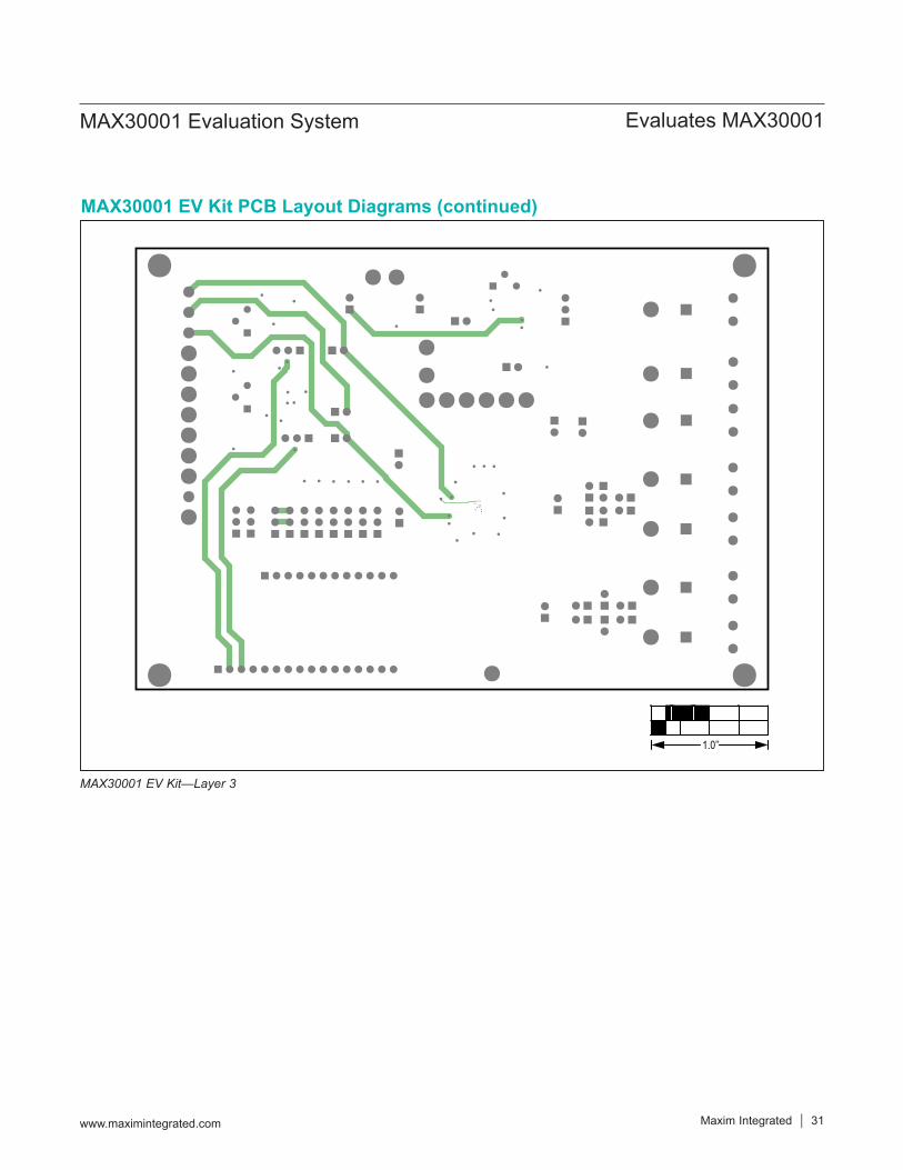
MAX30001 EV Kit—Layer 3
MAX30001 EV Kit PCB Layout Diagrams (continued)
1.0’’

Maxim Integrated │ 32www.maximintegrated.com
Evaluates MAX30001MAX30001 Evaluation System
MAX30001 EV Kit—Bottom
MAX30001 EV Kit PCB Layout Diagrams (continued)
1.0’’

Maxim Integrated │ 33www.maximintegrated.com
Evaluates MAX30001MAX30001 Evaluation System
MAX30001 EV Kit—Bottom Silkscreen
MAX30001 EV Kit PCB Layout Diagrams (continued)
1.0’’

Maxim Integrated cannot assume responsibility for use of any circuitry other than circuitry entirely embodied in a Maxim Integrated product. No circuit patent licenses are implied. Maxim Integrated reserves the right to change the circuitry and specifications without notice at any time.
Maxim Integrated and the Maxim Integrated logo are trademarks of Maxim Integrated Products, Inc. © 2017 Maxim Integrated Products, Inc. │ 34
Evaluates MAX30001MAX30001 Evaluation System
REVISIONNUMBER
REVISIONDATE DESCRIPTION PAGES
CHANGED
0 10/17 Initial release —
Revision History
For pricing, delivery, and ordering information, please contact Maxim Direct at 1-888-629-4642, or visit Maxim Integrated’s website at www.maximintegrated.com.