Embed Size (px)
Citation preview
Matrix Lane HardwareManual
Version: February 2007

Table of Contents
INTRODUCTION ................................................................................................................................................ 1
HARDWARE OVERVIEW................................................................................................................................. 2
MATRIX CHASSIS. ............................................................................................................................................... 5SVGA DISPLAY MONITORS................................................................................................................................ 9KEYBOARD MODULE ........................................................................................................................................ 10MACHINE INTERFACE MODULE ........................................................................................................................ 12
1. Machine Start Connection ...................................................................................................................... 142. Tenth Frame (& No-Tap) Cycle .............................................................................................................. 143. AMF Style Foul Input.............................................................................................................................. 144. Ball Speed Sensing.................................................................................................................................. 155. Strike / Bumper Bowling Contacts .......................................................................................................... 16
Connection to various Pinsetter/Pinspotter brands & types .....................................................................................181. AMF 8270 - 5 board or Omega Tek (No APS) chassis .................................................................................182. Brunswick Model A and A2 ...........................................................................................................................193.1 AMF 8270 (MK expander Board fitted) – Rake Switched fitted..................................................................203.2 AMF 8270 (MP chassis or CT chassis) – (Rake Switches Fitted). ...............................................................213.3 AMF 8270 (MP Chassis or CT chassis) – (No Rake Switched fitted)..........................................................224. AMF 8290XL Small Chassis Connection.......................................................................................................235. AMF 82-90 Large Chassis or existng AccuScore Connection........................................................................26
Connection to AMF MCU (Manager’s Control Unit) for machine control. ..................................................296. Brunswick GS92-98 Brands Connection ........................................................................................................307. Brunswick GS-X Connection .........................................................................................................................31
LANE SCORING CAMERA .................................................................................................................................. 33BALL SPEED SENSOR ........................................................................................................................................ 35
SAFETY PRECAUTIONS & HARDWARE DISCLAIMER......................................................................... 36
HARDWARE ISSUES ....................................................................................................................................... 37
MATRIX CHASSIS .............................................................................................................................................. 37SVGA DISPLAY MONITORS.............................................................................................................................. 37KEYBOARD ....................................................................................................................................................... 37MACHINE INTERFACE MODUIE......................................................................................................................... 38LANE SCORING CAMERA .................................................................................................................................. 39BALL SPEED SENSORS ...................................................................................................................................... 40
LANE HARDWARE 1
IntroductionThe following manual describes the Hardware configuration of the VanTech ComscoreMatrix Model of Tenpin Bowling Scoring Equipment. The system that has been createdaround this hardware is the result of fifteen years of experience in producing and servicingscoring systems. The name Matrix results from the fact that the main display hardwarecontrols a maximum of six lanes.
The following design principles were used to create the system.1. SafetyPlease refer to the following Section Safety Precautions.
2. Simplicity, Reliability, Ease of Installation and Servicing.These four principles relate to each other. Eliminating unnecessary complications to
the hardware configuration results in a system that is easy to install and service as well asimproving reliability. An intelligent mix of industry standard and custom designed hardwareresults in a system that is tailored for bowling, combining the flexibility of readily availablediagnostic tools without an awkward configuration. All inputs in the lane hardware areTransient Absorber (Transorb) and Ferrite Bead Protected to reduce the possibility of damageto the electronics due to electrical fluctuations. Use of reliable, solid mountings andconnectors with consideration to vibration and dirt, results in improved reliability.
3. Performance. A High Speed CPU, separate PCI (Peripheral Component Interconnect) Video
controllers, 100Mbit Ethernet Networking and Windows XP technology results in a systemcapable of impressive performance.
The VanTech Comscore system has been designed to divide the hardware intoseparate logical modules in order to simplify Troubleshooting and Maintenance. In mostcases it should be obvious in which module the problems lies. These modules do howeverrelate to each other and therefore can sometimes require some testing to determine whichmodule is at fault.
A general guiding principle is to trial the suspected faulty module in another knowngood pair in order to establish that the problem follows the suspect module. Once it has beendefinitely established that the module is faulty, it can be returned to a VanTech ComscoreAgent for service.
LANE HARDWARE 2
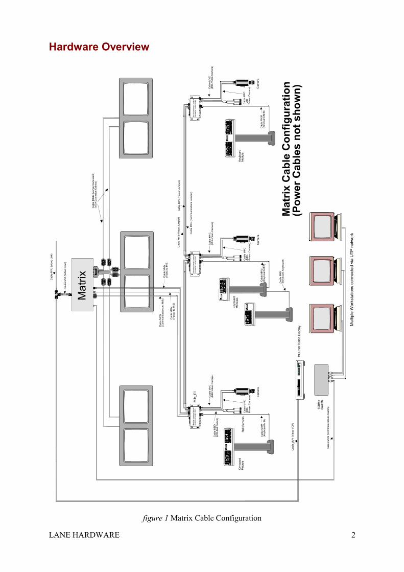
Hardware Overview
figure 1 Matrix Cable Configuration
LANE HARDWARE 3
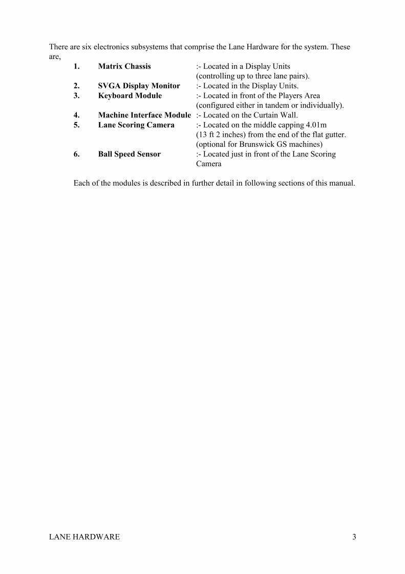
There are six electronics subsystems that comprise the Lane Hardware for the system. Theseare,
1. Matrix Chassis :- Located in a Display Units(controlling up to three lane pairs).
2. SVGA Display Monitor :- Located in the Display Units.3. Keyboard Module :- Located in front of the Players Area
(configured either in tandem or individually).4. Machine Interface Module :- Located on the Curtain Wall.5. Lane Scoring Camera :- Located on the middle capping 4.01m
(13 ft 2 inches) from the end of the flat gutter.(optional for Brunswick GS machines)
6. Ball Speed Sensor :- Located just in front of the Lane Scoring Camera
Each of the modules is described in further detail in following sections of this manual.
LANE HARDWARE 4
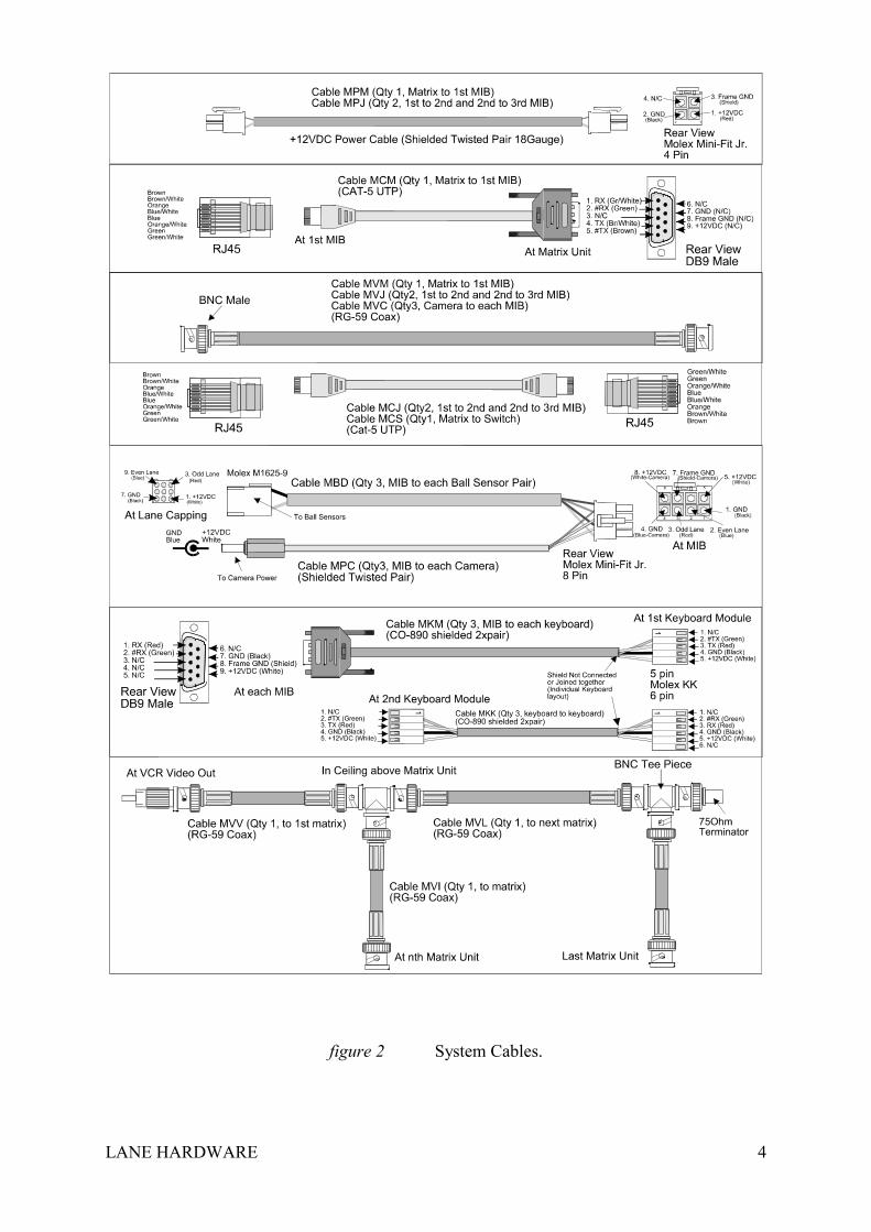
figure 2 System Cables.
LANE HARDWARE 5
Matrix Chassis.The Matrix Chassis is a self-contained enclosure mounted one of the Display units
controlling up to six lanes. Access can be gained by opening the access door in the rear of thedisplay units, between the two SVGA display monitors. This chassis is responsible forcommunicating with the Front Office Computer, Keyboards & Machine Interface Modules,displaying the Lane Score Grids, displaying Video and determining the Score based on theinput from the Lane Scoring Cameras. It is designed so that the only service to be performedby the center technician on the Matrix Chassis is to replace it with a spare if necessary. Allother service to the electronics inside the chassis is to be done by an authorised VanTechComscore agent only.
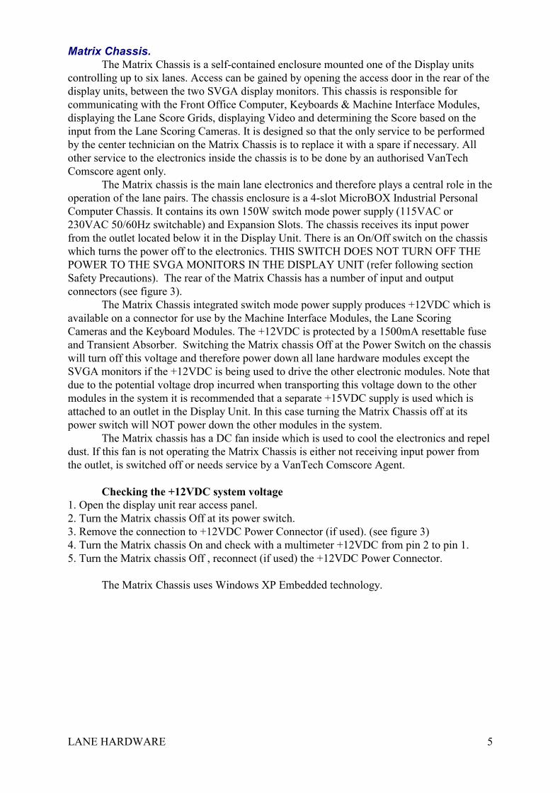
The Matrix chassis is the main lane electronics and therefore plays a central role in theoperation of the lane pairs. The chassis enclosure is a 4-slot MicroBOX Industrial PersonalComputer Chassis. It contains its own 150W switch mode power supply (115VAC or230VAC 50/60Hz switchable) and Expansion Slots. The chassis receives its input powerfrom the outlet located below it in the Display Unit. There is an On/Off switch on the chassiswhich turns the power off to the electronics. THIS SWITCH DOES NOT TURN OFF THEPOWER TO THE SVGA MONITORS IN THE DISPLAY UNIT (refer following sectionSafety Precautions). The rear of the Matrix Chassis has a number of input and outputconnectors (see figure 3).
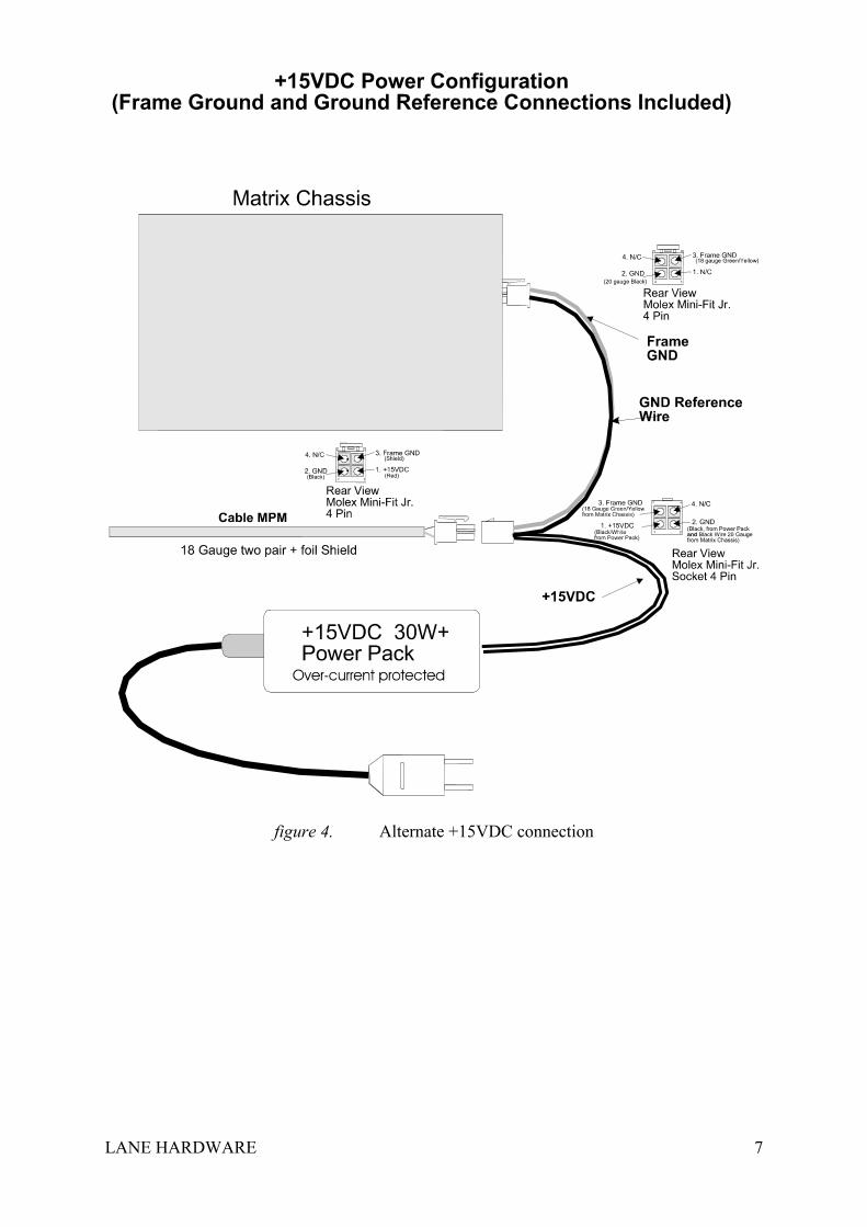
The Matrix Chassis integrated switch mode power supply produces +12VDC which isavailable on a connector for use by the Machine Interface Modules, the Lane ScoringCameras and the Keyboard Modules. The +12VDC is protected by a 1500mA resettable fuseand Transient Absorber. Switching the Matrix chassis Off at the Power Switch on the chassiswill turn off this voltage and therefore power down all lane hardware modules except theSVGA monitors if the +12VDC is being used to drive the other electronic modules. Note thatdue to the potential voltage drop incurred when transporting this voltage down to the othermodules in the system it is recommended that a separate +15VDC supply is used which isattached to an outlet in the Display Unit. In this case turning the Matrix Chassis off at itspower switch will NOT power down the other modules in the system.
The Matrix chassis has a DC fan inside which is used to cool the electronics and repeldust. If this fan is not operating the Matrix Chassis is either not receiving input power fromthe outlet, is switched off or needs service by a VanTech Comscore Agent.
Checking the +12VDC system voltage1. Open the display unit rear access panel.2. Turn the Matrix chassis Off at its power switch.3. Remove the connection to +12VDC Power Connector (if used). (see figure 3)4. Turn the Matrix chassis On and check with a multimeter +12VDC from pin 2 to pin 1.5. Turn the Matrix chassis Off , reconnect (if used) the +12VDC Power Connector.
The Matrix Chassis uses Windows XP Embedded technology.
LANE HARDWARE 6
figure 3. Rear of Matrix Chassis
LANE HARDWARE 7
figure 4. Alternate +15VDC connection
LANE HARDWARE 8
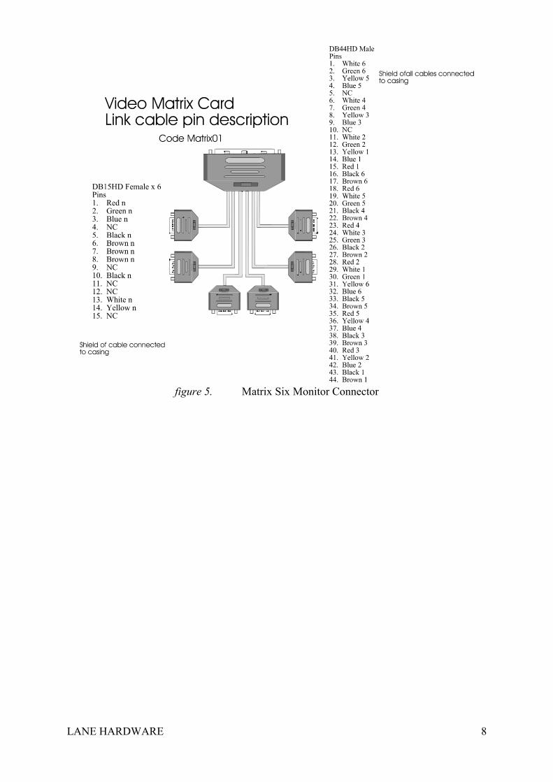
figure 5. Matrix Six Monitor Connector

LANE HARDWARE 9
SVGA Display Monitors
The two SVGA Display Monitors located in the Display Unit are industry standardsuperVGA display monitors. The exact brand and size monitor varies.
They have an industry standard superVGA DB15HD input which is connected to theMatrix Chassis via the six Monitor Connector (see figure 2). They use the same style of signalthat travels between a standard Computer & Monitor. They have a 115VAC or 230VAC(depending on the brand of monitor) 50/60Hz voltage power input and are connected to aPower Outlet located inside the Display Units.
There are a number of adjustments on the SVGA monitors that allow the scoring gridsto be widened, positioned within the screen and brightened. Refer to monitor manufacturer’sService and Safety Instructions for more details relating to monitor adjustments. Contact yourVanTech Comscore Agent for this information.
The monitors are a high voltage device and as such should only be serviced byAuthorised Personnel. They are accessed via an individual cover at the rear of the DisplayUnit, which should never be removed with the monitors operating (refer following sectionSafety Precautions).
LANE HARDWARE 10
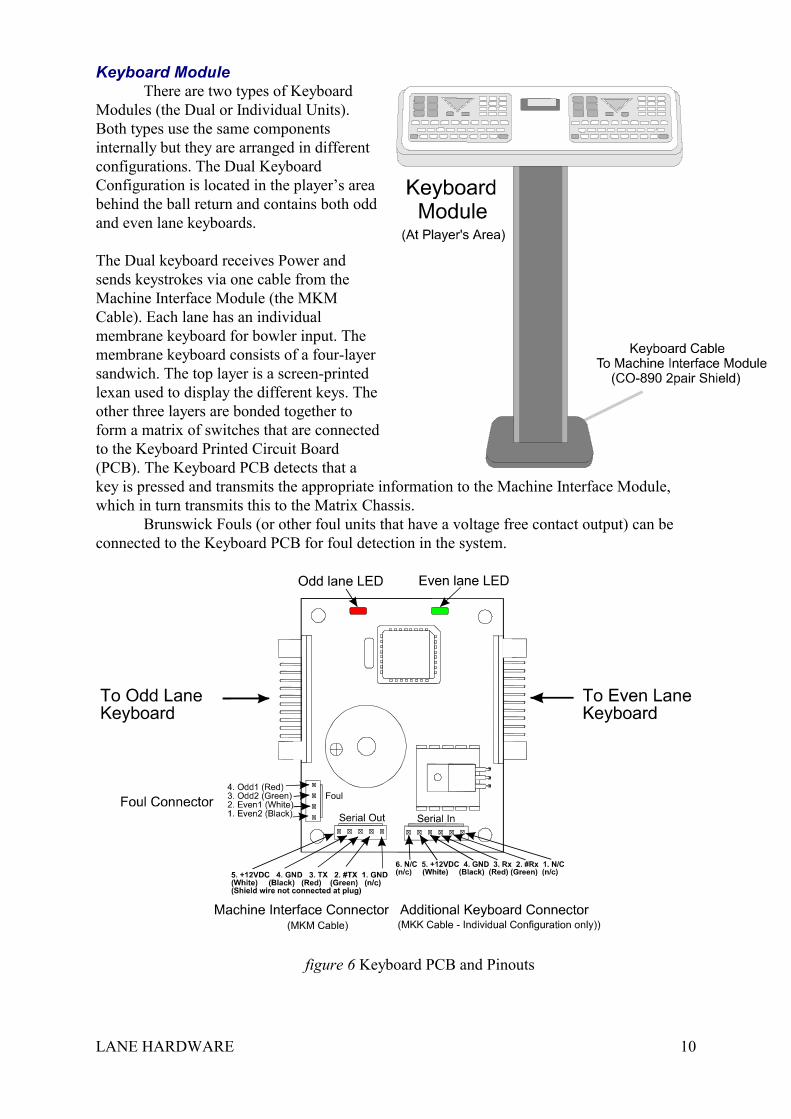
Keyboard ModuleThere are two types of Keyboard
Modules (the Dual or Individual Units).Both types use the same componentsinternally but they are arranged in differentconfigurations. The Dual KeyboardConfiguration is located in the player’s areabehind the ball return and contains both oddand even lane keyboards.
The Dual keyboard receives Power andsends keystrokes via one cable from theMachine Interface Module (the MKMCable). Each lane has an individualmembrane keyboard for bowler input. Themembrane keyboard consists of a four-layersandwich. The top layer is a screen-printedlexan used to display the different keys. Theother three layers are bonded together toform a matrix of switches that are connectedto the Keyboard Printed Circuit Board(PCB). The Keyboard PCB detects that akey is pressed and transmits the appropriate information to the Machine Interface Module,which in turn transmits this to the Matrix Chassis.
Brunswick Fouls (or other foul units that have a voltage free contact output) can beconnected to the Keyboard PCB for foul detection in the system.
figure 6 Keyboard PCB and Pinouts
LANE HARDWARE 11
The Keyboard Printed Circuit Board (PCB) has a piezo-electric buzzer, which beeps when akey is pressed on either lane and will give a long tone followed by two short tones when the+12VDC power is first applied from the Matrix chassis (or separate Power Supply). If a key islocked down by a fault in one of the membrane keyboards, the keyboard will indicate anothershort tone (4 beeps at start up). The Keyboard PCB has two indicating LEDs (Light EmittingDiode). The Red LED indicates a key press on the Odd Lane. The Green LED indicates a keypress on the Even Lane.
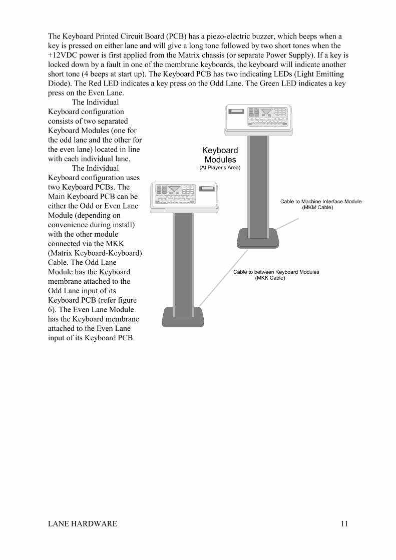
The IndividualKeyboard configurationconsists of two separatedKeyboard Modules (one forthe odd lane and the other forthe even lane) located in linewith each individual lane.
The IndividualKeyboard configuration usestwo Keyboard PCBs. TheMain Keyboard PCB can beeither the Odd or Even LaneModule (depending onconvenience during install)with the other moduleconnected via the MKK(Matrix Keyboard-Keyboard)Cable. The Odd LaneModule has the Keyboardmembrane attached to theOdd Lane input of itsKeyboard PCB (refer figure6). The Even Lane Modulehas the Keyboard membraneattached to the Even Laneinput of its Keyboard PCB.
LANE HARDWARE 12
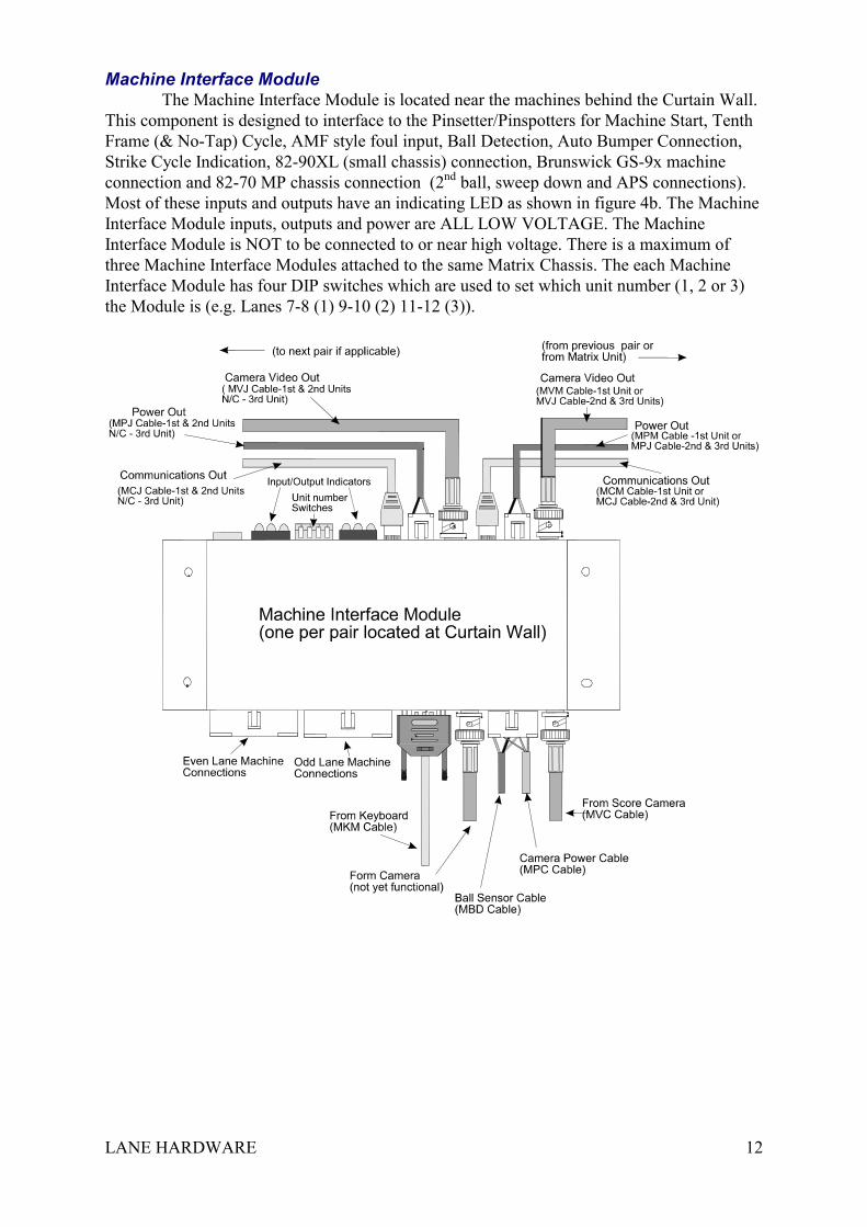
Machine Interface Module The Machine Interface Module is located near the machines behind the Curtain Wall.
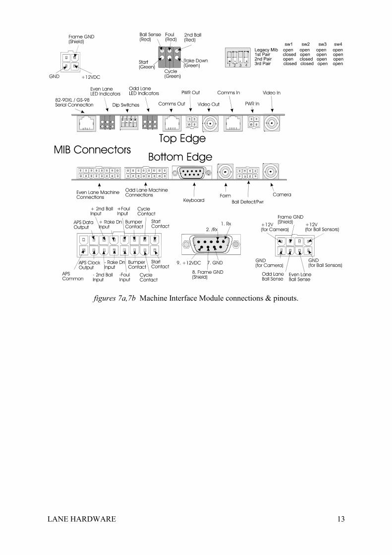
This component is designed to interface to the Pinsetter/Pinspotters for Machine Start, TenthFrame (& No-Tap) Cycle, AMF style foul input, Ball Detection, Auto Bumper Connection,Strike Cycle Indication, 82-90XL (small chassis) connection, Brunswick GS-9x machineconnection and 82-70 MP chassis connection (2nd ball, sweep down and APS connections).Most of these inputs and outputs have an indicating LED as shown in figure 4b. The MachineInterface Module inputs, outputs and power are ALL LOW VOLTAGE. The MachineInterface Module is NOT to be connected to or near high voltage. There is a maximum ofthree Machine Interface Modules attached to the same Matrix Chassis. The each MachineInterface Module has four DIP switches which are used to set which unit number (1, 2 or 3)the Module is (e.g. Lanes 7-8 (1) 9-10 (2) 11-12 (3)).
LANE HARDWARE 13
figures 7a,7b Machine Interface Module connections & pinouts.
LANE HARDWARE 14
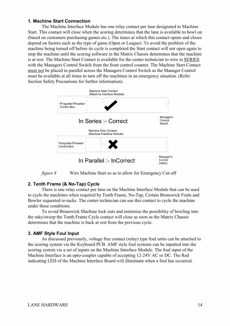
1. Machine Start ConnectionThe Machine Interface Module has one relay contact per lane designated to Machine
Start. This contact will close when the scoring determines that the lane is available to bowl on(based on customers purchasing games etc.). The times at which this contact opens and closesdepend on factors such as the type of game (Open or League). To avoid the problem of themachine being turned off before its cycle is completed the Start contact will not open again tostop the machine until the scoring software in the Matrix Chassis determines that the machineis at rest. The Machine Start Contact is available for the center technician to wire in SERIESwith the Managers Control Switch from the front control counter. The Machine Start Contactmust not be placed in parallel across the Managers Control Switch as the Manager Controlmust be available at all times to turn off the machines in an emergency situation. (ReferSection Safety Precautions for further information).
figure 8 Wire Machine Start so as to allow for Emergency Cut-off
2. Tenth Frame (& No-Tap) CycleThere is one relay contact per lane on the Machine Interface Module that can be used
to cycle the machines when required by Tenth Frame, No-Tap, Certain Brunswick Fouls andBowler requested re-racks. The center technician can use this contact to cycle the machineunder these conditions.
To avoid Brunswick Machine lock outs and minimise the possibility of bowling intothe rake/sweep the Tenth Frame Cycle contact will close as soon as the Matrix Chassisdetermines that the machine is back at rest from the previous cycle.
3. AMF Style Foul InputAs discussed previously, voltage free contact (relay) type foul units can be attached to
the scoring system via the Keyboard PCB. AMF style foul systems can be inputted into thescoring system via a set of inputs on the Machine Interface Module. The foul input of theMachine Interface is an opto-coupler capable of accepting 12-24V AC or DC. The Redindicating LED of the Machine Interface Board will illuminate when a foul has occurred.
LANE HARDWARE 15
4. Ball Speed SensingThe Ball Speed Sensing input of the Machine Interface Module for each lane is used
to determine the speed of a ball bowled on the lane. It is attached via the Ball Speed SensorCable (MBD Cable) to a pair of Infrared Photo-switches located near the lane ScoringCamera. This feature allows the bowlers to view their bowling speed. It also notifies thesystem that a ball has been bowled prior to a machine cycle. The Matrix Chassis uses thisinformation to determine whether the current score is a valid score bowled by the bowler or acycle operated by the ball return or mechanics cycle button. If the ball detection facility hasbeen enabled in the system settings, the Matrix Chassis will not display any score that was notpreceded by a ball speed signal from the Machine Interface Module. This feature is notessential to scoring but is convenient to reducing the number of score corrections produced bymachine faults.
Ball Speed Sensing and ball detection is a completely separate function to Light Balltriggering which is triggering (cycling) the machine by sensing a ball passing through thefront of the machine. Computer Score does not implement Light Ball triggering. The Scoringsystem does not require the machines to be triggered via light ball triggering devices. TheMatrix Chassis does, however, have facilities within its software to communicate withseparate light ball triggering software. Ebonite-Vantage has produced such a program (calledVanTechTrigger.exe). VanTechTrigger.exe can be loaded onto the Matrix Chassis. Thisprogram communicates with the Matrix Software and it able to determine when Ball SpeedSensing inputs have occurred and subsequently order the Matrix to cycle the lanes (via theMachine Cycle Contact of the Machine Interface Module) at the appropriate time. ComputerScore accepts no liability for the Safety of any such system used. Refer to Ebonite-Vantagefor all information regarding the operation and safety of this software.
LANE HARDWARE 16
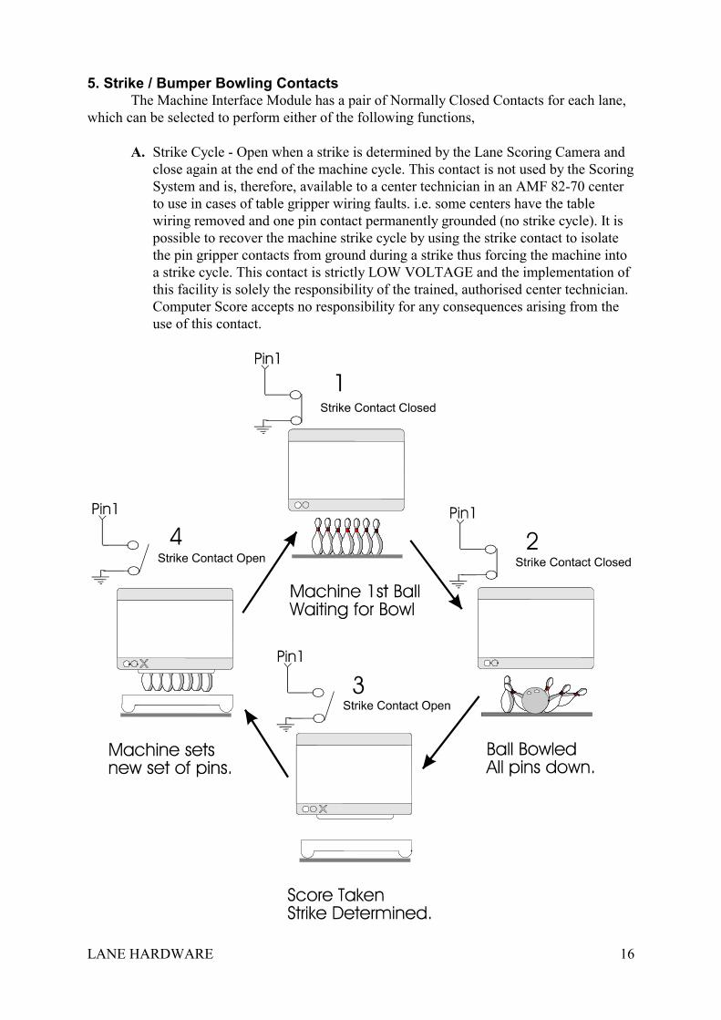
5. Strike / Bumper Bowling ContactsThe Machine Interface Module has a pair of Normally Closed Contacts for each lane,
which can be selected to perform either of the following functions,
A. Strike Cycle - Open when a strike is determined by the Lane Scoring Camera andclose again at the end of the machine cycle. This contact is not used by the ScoringSystem and is, therefore, available to a center technician in an AMF 82-70 centerto use in cases of table gripper wiring faults. i.e. some centers have the tablewiring removed and one pin contact permanently grounded (no strike cycle). It ispossible to recover the machine strike cycle by using the strike contact to isolatethe pin gripper contacts from ground during a strike thus forcing the machine intoa strike cycle. This contact is strictly LOW VOLTAGE and the implementation ofthis facility is solely the responsibility of the trained, authorised center technician.Computer Score accepts no responsibility for any consequences arising from theuse of this contact.
LANE HARDWARE 17
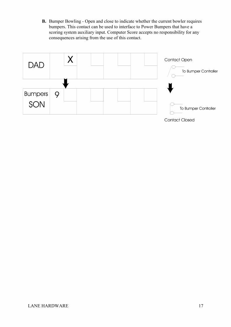
B. Bumper Bowling - Open and close to indicate whether the current bowler requiresbumpers. This contact can be used to interface to Power Bumpers that have ascoring system auxiliary input. Computer Score accepts no responsibility for anyconsequences arising from the use of this contact.
LANE HARDWARE 18
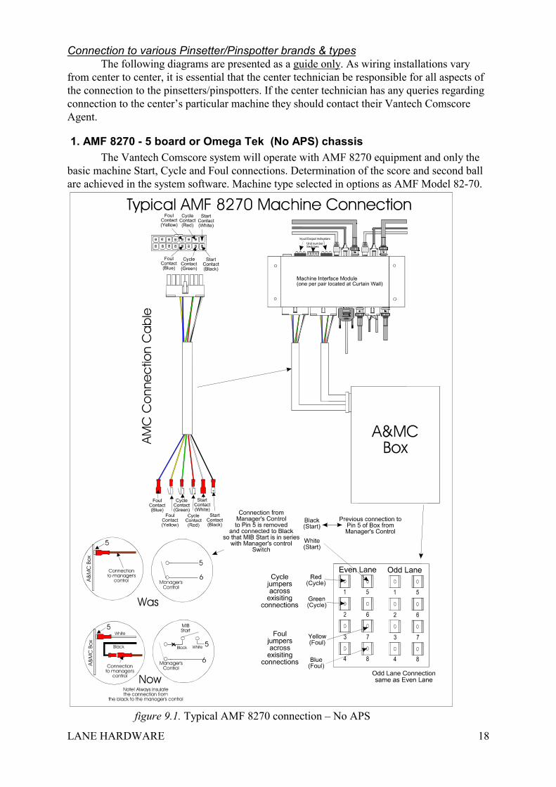
Connection to various Pinsetter/Pinspotter brands & typesThe following diagrams are presented as a guide only. As wiring installations vary
from center to center, it is essential that the center technician be responsible for all aspects ofthe connection to the pinsetters/pinspotters. If the center technician has any queries regardingconnection to the center’s particular machine they should contact their Vantech ComscoreAgent.
1. AMF 8270 - 5 board or Omega Tek (No APS) chassisThe Vantech Comscore system will operate with AMF 8270 equipment and only the
basic machine Start, Cycle and Foul connections. Determination of the score and second ballare achieved in the system software. Machine type selected in options as AMF Model 82-70.
figure 9.1. Typical AMF 8270 connection – No APS
LANE HARDWARE 19
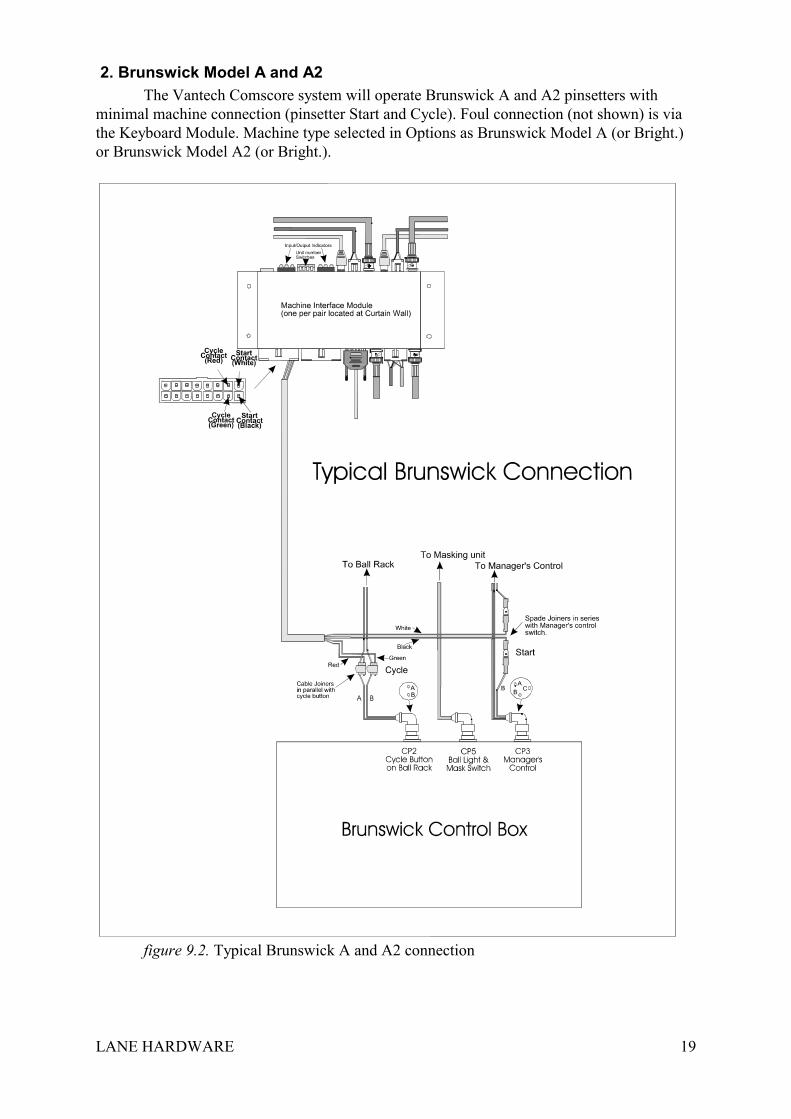
2. Brunswick Model A and A2The Vantech Comscore system will operate Brunswick A and A2 pinsetters with
minimal machine connection (pinsetter Start and Cycle). Foul connection (not shown) is viathe Keyboard Module. Machine type selected in Options as Brunswick Model A (or Bright.)or Brunswick Model A2 (or Bright.).
figure 9.2. Typical Brunswick A and A2 connection
LANE HARDWARE 20
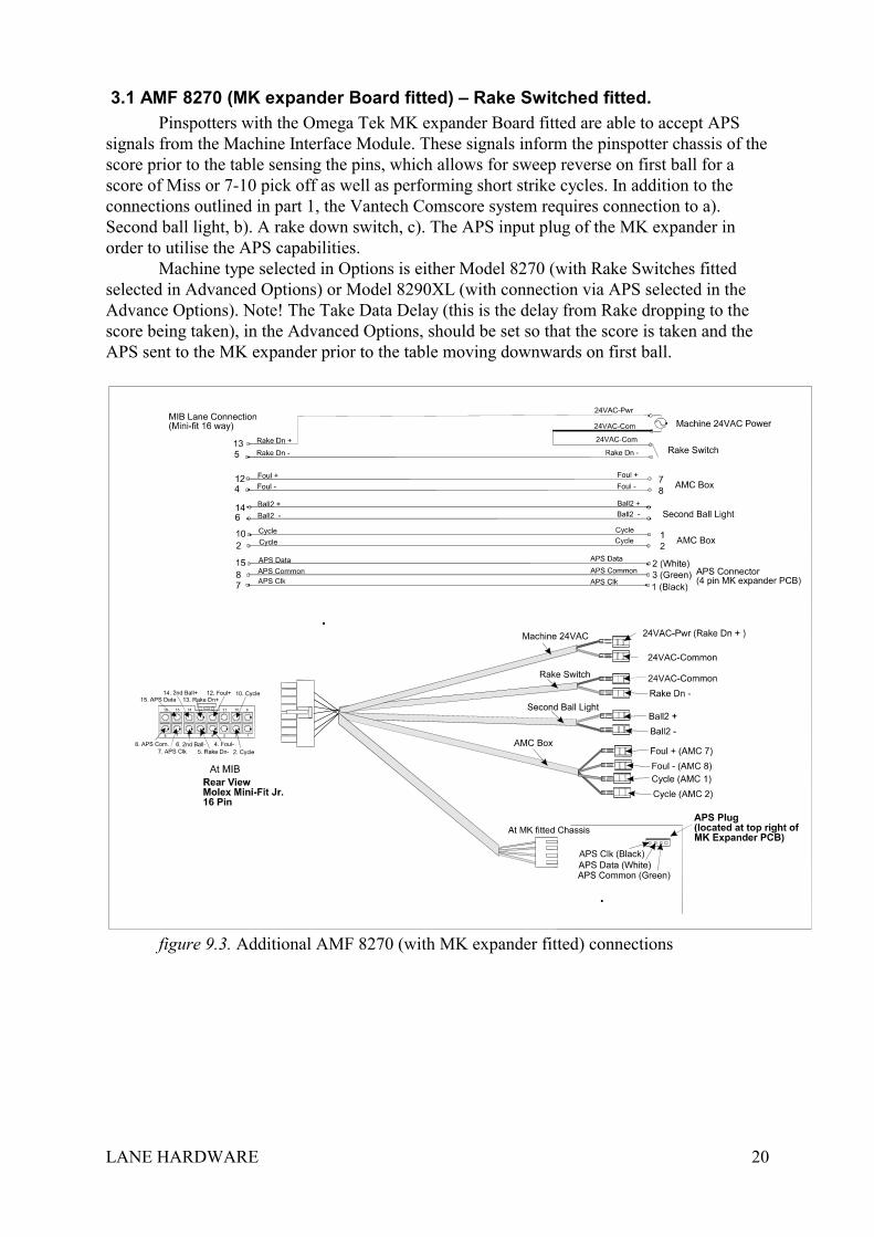
3.1 AMF 8270 (MK expander Board fitted) – Rake Switched fitted.Pinspotters with the Omega Tek MK expander Board fitted are able to accept APS
signals from the Machine Interface Module. These signals inform the pinspotter chassis of thescore prior to the table sensing the pins, which allows for sweep reverse on first ball for ascore of Miss or 7-10 pick off as well as performing short strike cycles. In addition to theconnections outlined in part 1, the Vantech Comscore system requires connection to a).Second ball light, b). A rake down switch, c). The APS input plug of the MK expander inorder to utilise the APS capabilities.
Machine type selected in Options is either Model 8270 (with Rake Switches fittedselected in Advanced Options) or Model 8290XL (with connection via APS selected in theAdvance Options). Note! The Take Data Delay (this is the delay from Rake dropping to thescore being taken), in the Advanced Options, should be set so that the score is taken and theAPS sent to the MK expander prior to the table moving downwards on first ball.
figure 9.3. Additional AMF 8270 (with MK expander fitted) connections
LANE HARDWARE 21
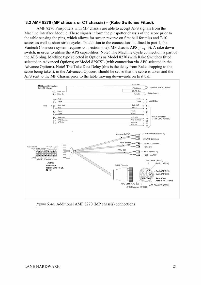
3.2 AMF 8270 (MP chassis or CT chassis) – (Rake Switches Fitted).AMF 8270 Pinspotters with MP chassis are able to accept APS signals from the
Machine Interface Module. These signals inform the pinspotter chassis of the score prior tothe table sensing the pins, which allows for sweep reverse on first ball for miss and 7-10scores as well as short strike cycles. In addition to the connections outlined in part 1, theVantech Comscore system requires connection to a). MP chassis APS plug, b). A rake downswitch, in order to utilise the APS capabilities. Note! The Machine Cycle connection is part ofthe APS plug. Machine type selected in Options as Model 8270 (with Rake Switches fittedselected in Advanced Options) or Model 8290XL (with connection via APS selected in theAdvance Options). Note! The Take Data Delay (this is the delay from Rake dropping to thescore being taken), in the Advanced Options, should be set so that the score is taken and theAPS sent to the MP Chassis prior to the table moving downwards on first ball.
figure 9.4a. Additional AMF 8270 (MP chassis) connections
LANE HARDWARE 22
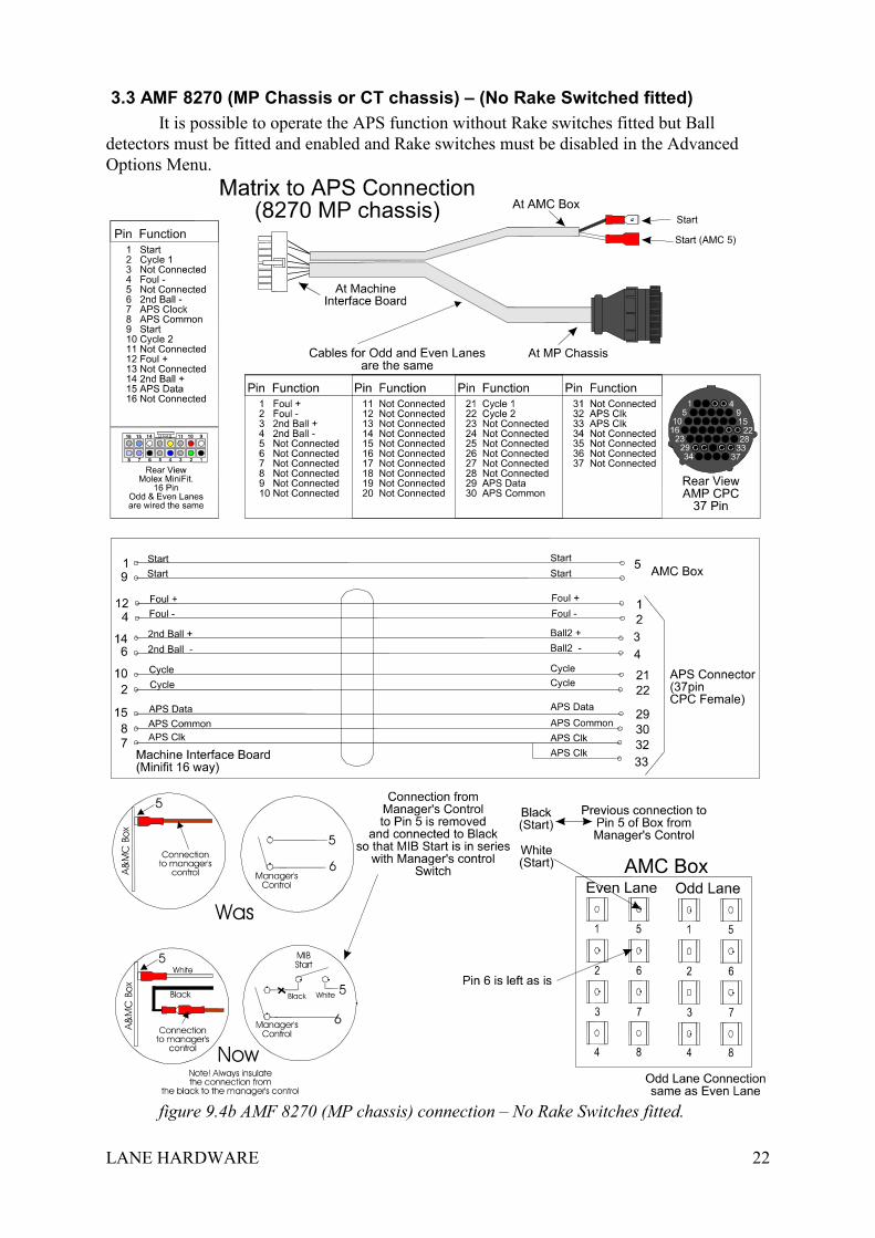
3.3 AMF 8270 (MP Chassis or CT chassis) – (No Rake Switched fitted)It is possible to operate the APS function without Rake switches fitted but Ball
detectors must be fitted and enabled and Rake switches must be disabled in the AdvancedOptions Menu.
figure 9.4b AMF 8270 (MP chassis) connection – No Rake Switches fitted.
LANE HARDWARE 23
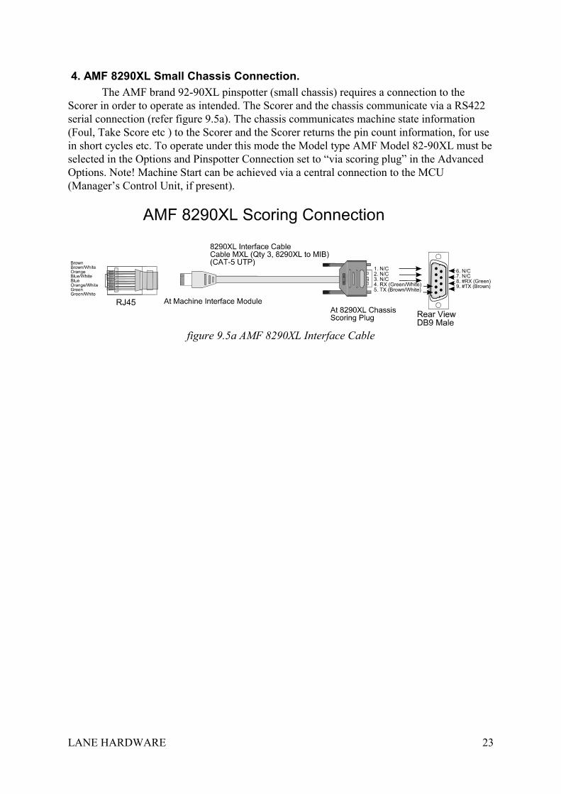
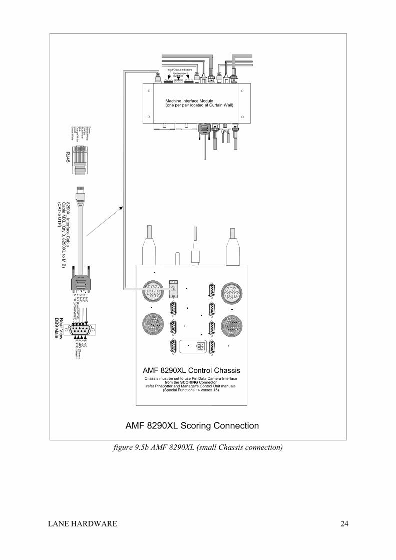
4. AMF 8290XL Small Chassis Connection.The AMF brand 92-90XL pinspotter (small chassis) requires a connection to the
Scorer in order to operate as intended. The Scorer and the chassis communicate via a RS422serial connection (refer figure 9.5a). The chassis communicates machine state information(Foul, Take Score etc ) to the Scorer and the Scorer returns the pin count information, for usein short cycles etc. To operate under this mode the Model type AMF Model 82-90XL must beselected in the Options and Pinspotter Connection set to “via scoring plug” in the AdvancedOptions. Note! Machine Start can be achieved via a central connection to the MCU(Manager’s Control Unit, if present).
figure 9.5a AMF 8290XL Interface Cable
LANE HARDWARE 24
figure 9.5b AMF 8290XL (small Chassis connection)
LANE HARDWARE 25
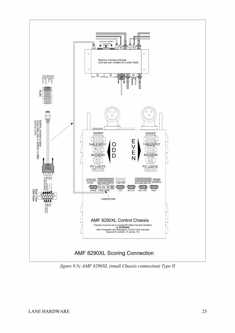
figure 9.5c AMF 8290XL (small Chassis connection) Type II
LANE HARDWARE 26
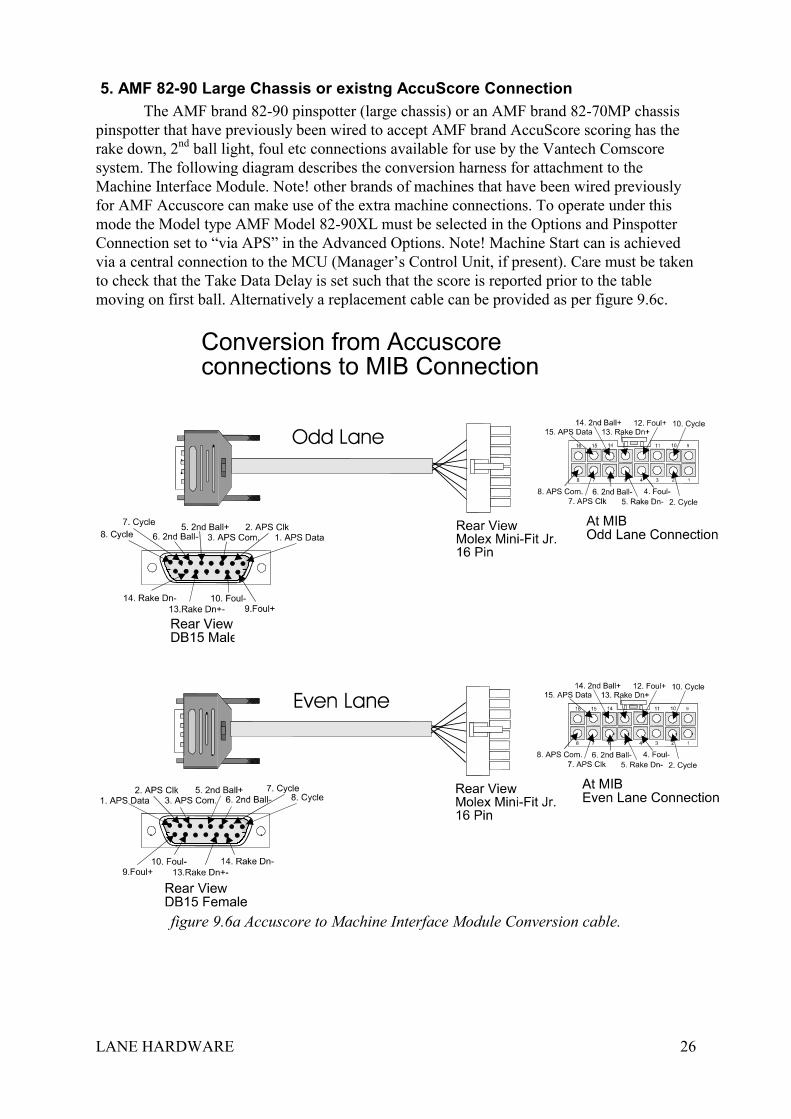
5. AMF 82-90 Large Chassis or existng AccuScore ConnectionThe AMF brand 82-90 pinspotter (large chassis) or an AMF brand 82-70MP chassis
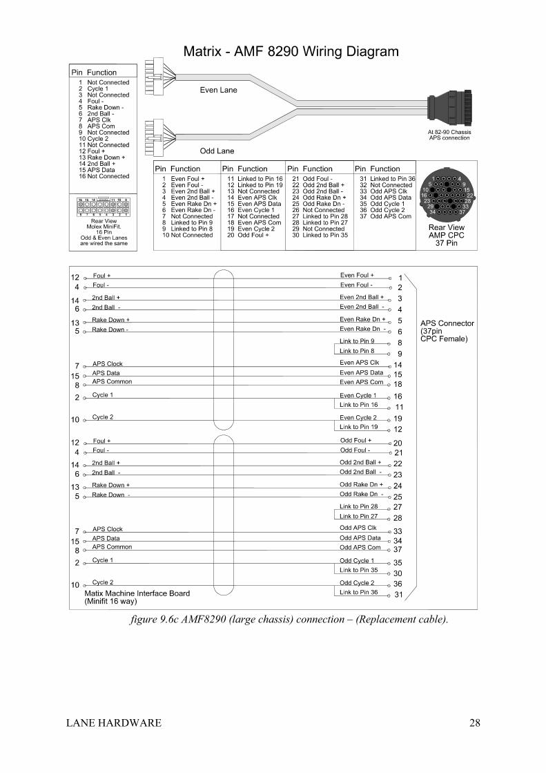
pinspotter that have previously been wired to accept AMF brand AccuScore scoring has therake down, 2nd ball light, foul etc connections available for use by the Vantech Comscoresystem. The following diagram describes the conversion harness for attachment to theMachine Interface Module. Note! other brands of machines that have been wired previouslyfor AMF Accuscore can make use of the extra machine connections. To operate under thismode the Model type AMF Model 82-90XL must be selected in the Options and PinspotterConnection set to “via APS” in the Advanced Options. Note! Machine Start can is achievedvia a central connection to the MCU (Manager’s Control Unit, if present). Care must be takento check that the Take Data Delay is set such that the score is reported prior to the tablemoving on first ball. Alternatively a replacement cable can be provided as per figure 9.6c.
figure 9.6a Accuscore to Machine Interface Module Conversion cable.
LANE HARDWARE 27
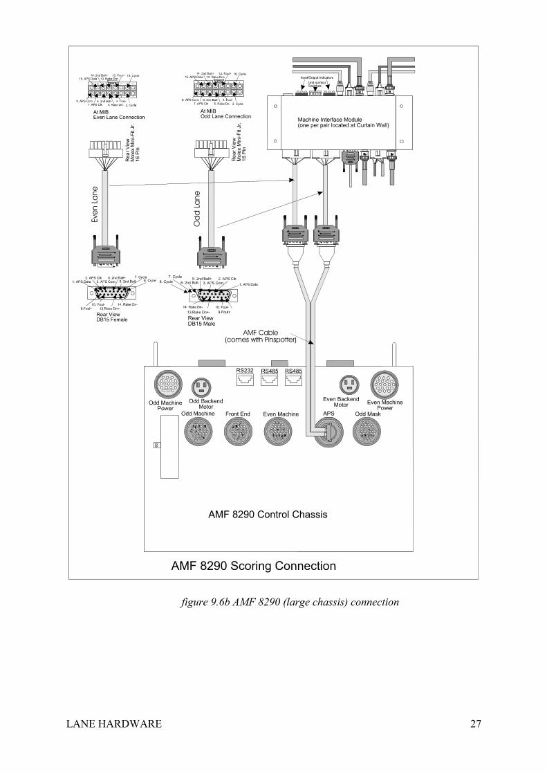
figure 9.6b AMF 8290 (large chassis) connection
LANE HARDWARE 28
figure 9.6c AMF8290 (large chassis) connection – (Replacement cable).
LANE HARDWARE 29
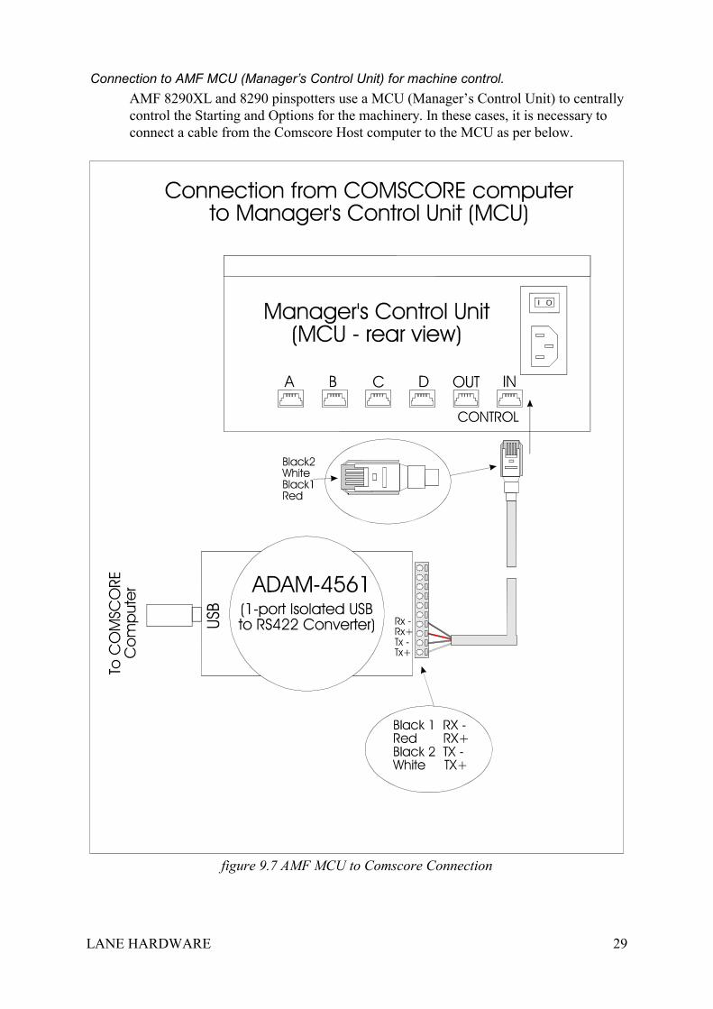
Connection to AMF MCU (Manager’s Control Unit) for machine control.AMF 8290XL and 8290 pinspotters use a MCU (Manager’s Control Unit) to centrallycontrol the Starting and Options for the machinery. In these cases, it is necessary toconnect a cable from the Comscore Host computer to the MCU as per below.
figure 9.7 AMF MCU to Comscore Connection
LANE HARDWARE 30
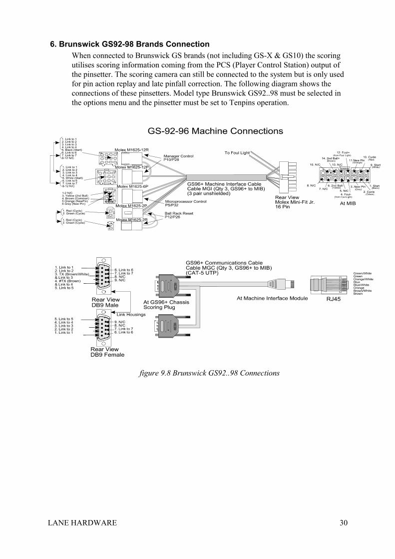
6. Brunswick GS92-98 Brands ConnectionWhen connected to Brunswick GS brands (not including GS-X & GS10) the scoringutilises scoring information coming from the PCS (Player Control Station) output ofthe pinsetter. The scoring camera can still be connected to the system but is only usedfor pin action replay and late pinfall correction. The following diagram shows theconnections of these pinsetters. Model type Brunswick GS92..98 must be selected inthe options menu and the pinsetter must be set to Tenpins operation.
figure 9.8 Brunswick GS92..98 Connections
LANE HARDWARE 31
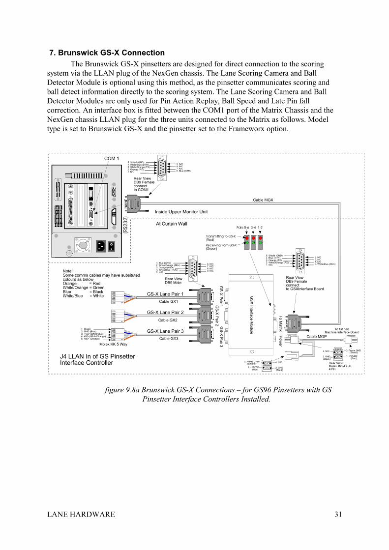
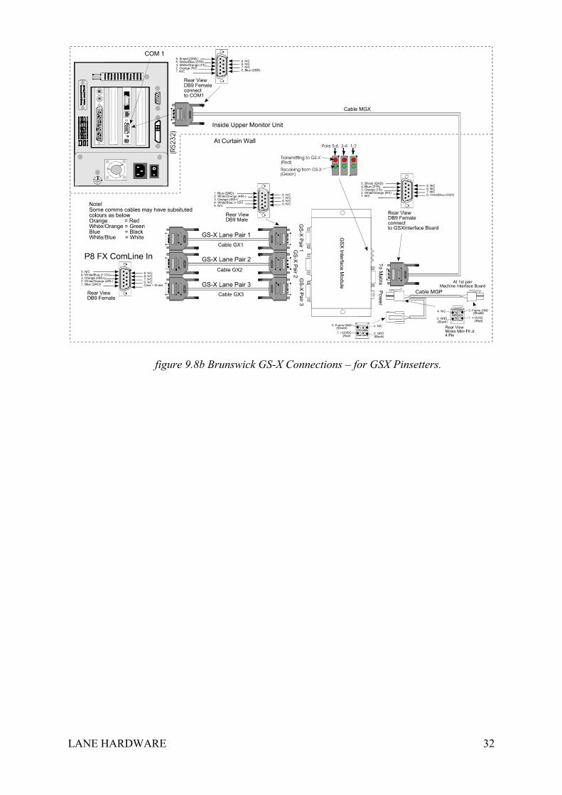
7. Brunswick GS-X ConnectionThe Brunswick GS-X pinsetters are designed for direct connection to the scoring
system via the LLAN plug of the NexGen chassis. The Lane Scoring Camera and BallDetector Module is optional using this method, as the pinsetter communicates scoring andball detect information directly to the scoring system. The Lane Scoring Camera and BallDetector Modules are only used for Pin Action Replay, Ball Speed and Late Pin fallcorrection. An interface box is fitted between the COM1 port of the Matrix Chassis and theNexGen chassis LLAN plug for the three units connected to the Matrix as follows. Modeltype is set to Brunswick GS-X and the pinsetter set to the Frameworx option.
figure 9.8a Brunswick GS-X Connections – for GS96 Pinsetters with GSPinsetter Interface Controllers Installed.
LANE HARDWARE 32
figure 9.8b Brunswick GS-X Connections – for GSX Pinsetters.
LANE HARDWARE 33
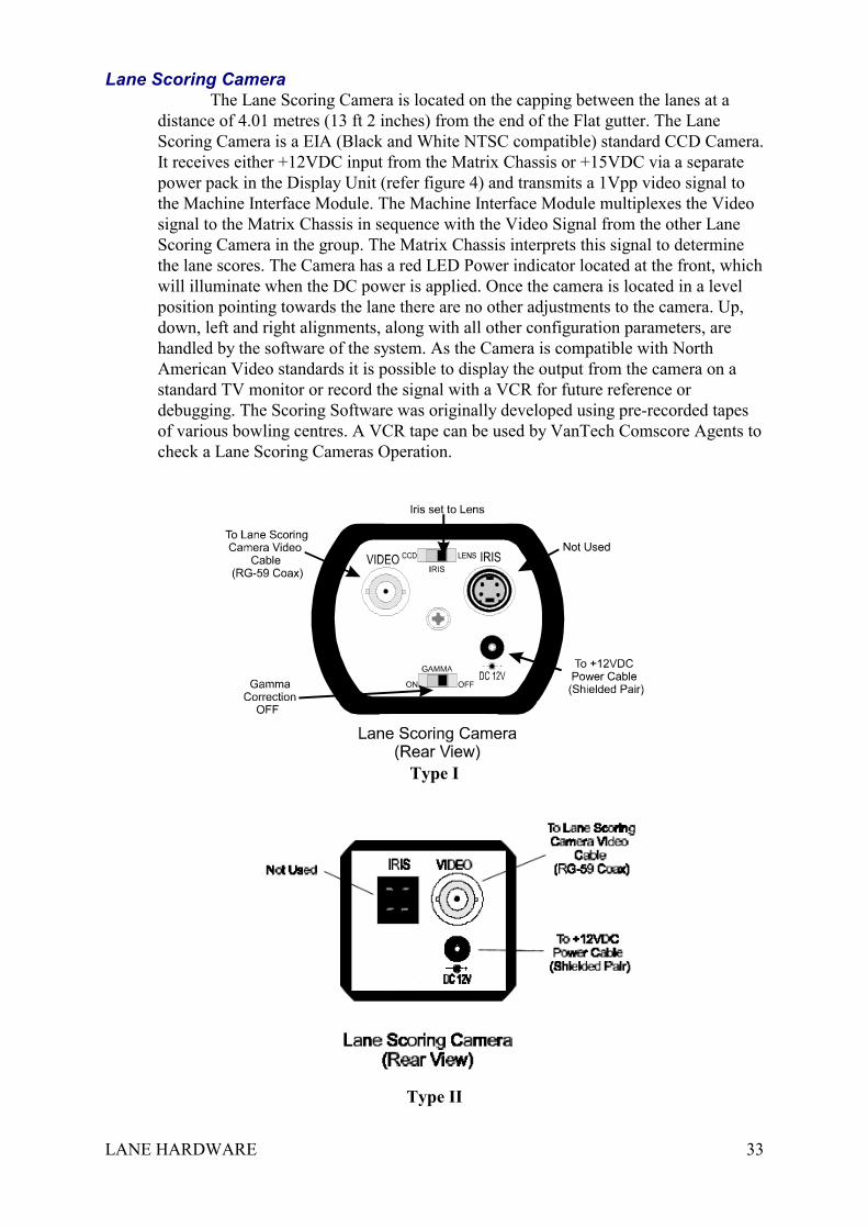
Lane Scoring CameraThe Lane Scoring Camera is located on the capping between the lanes at a
distance of 4.01 metres (13 ft 2 inches) from the end of the Flat gutter. The LaneScoring Camera is a EIA (Black and White NTSC compatible) standard CCD Camera.It receives either +12VDC input from the Matrix Chassis or +15VDC via a separatepower pack in the Display Unit (refer figure 4) and transmits a 1Vpp video signal tothe Machine Interface Module. The Machine Interface Module multiplexes the Videosignal to the Matrix Chassis in sequence with the Video Signal from the other LaneScoring Camera in the group. The Matrix Chassis interprets this signal to determinethe lane scores. The Camera has a red LED Power indicator located at the front, whichwill illuminate when the DC power is applied. Once the camera is located in a levelposition pointing towards the lane there are no other adjustments to the camera. Up,down, left and right alignments, along with all other configuration parameters, arehandled by the software of the system. As the Camera is compatible with NorthAmerican Video standards it is possible to display the output from the camera on astandard TV monitor or record the signal with a VCR for future reference ordebugging. The Scoring Software was originally developed using pre-recorded tapesof various bowling centres. A VCR tape can be used by VanTech Comscore Agents tocheck a Lane Scoring Cameras Operation.
Type I
Type II
LANE HARDWARE 34
Type I
Type II
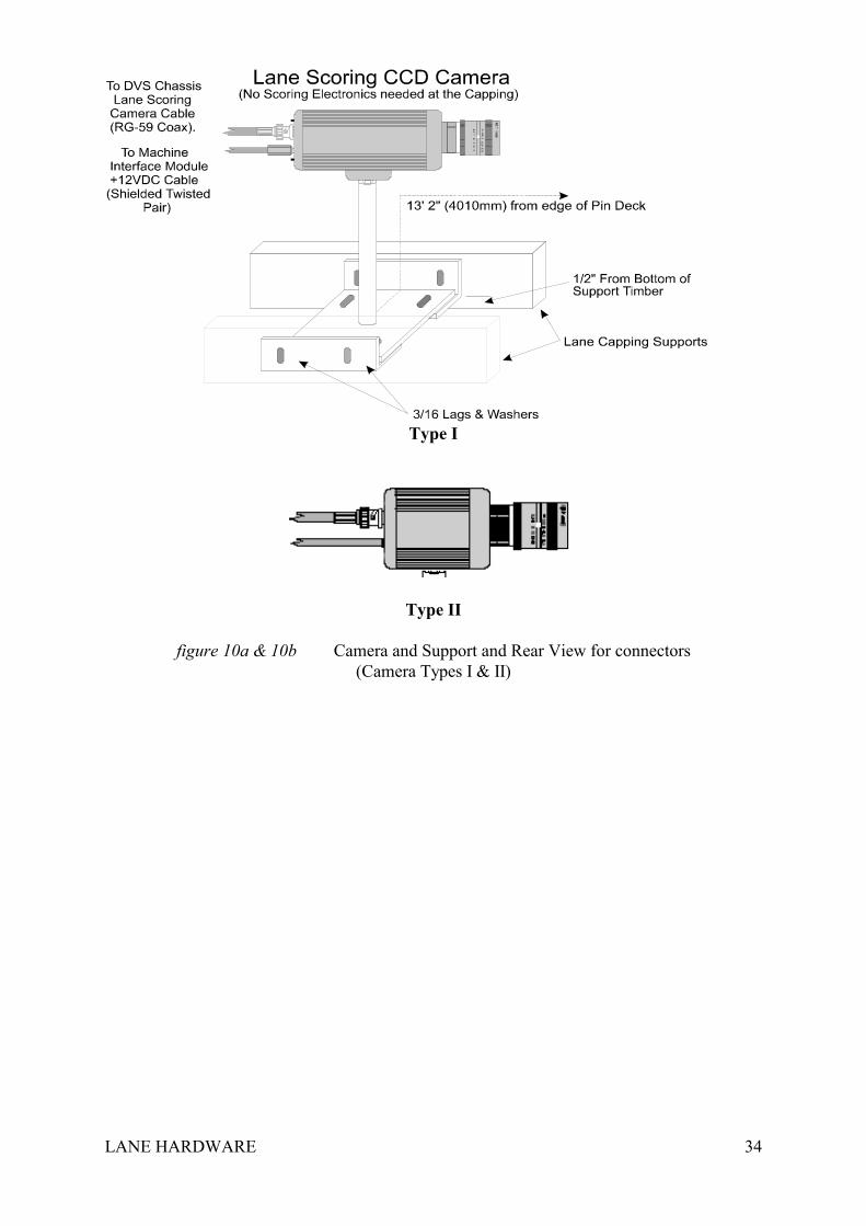
figure 10a & 10b Camera and Support and Rear View for connectors(Camera Types I & II)
LANE HARDWARE 35
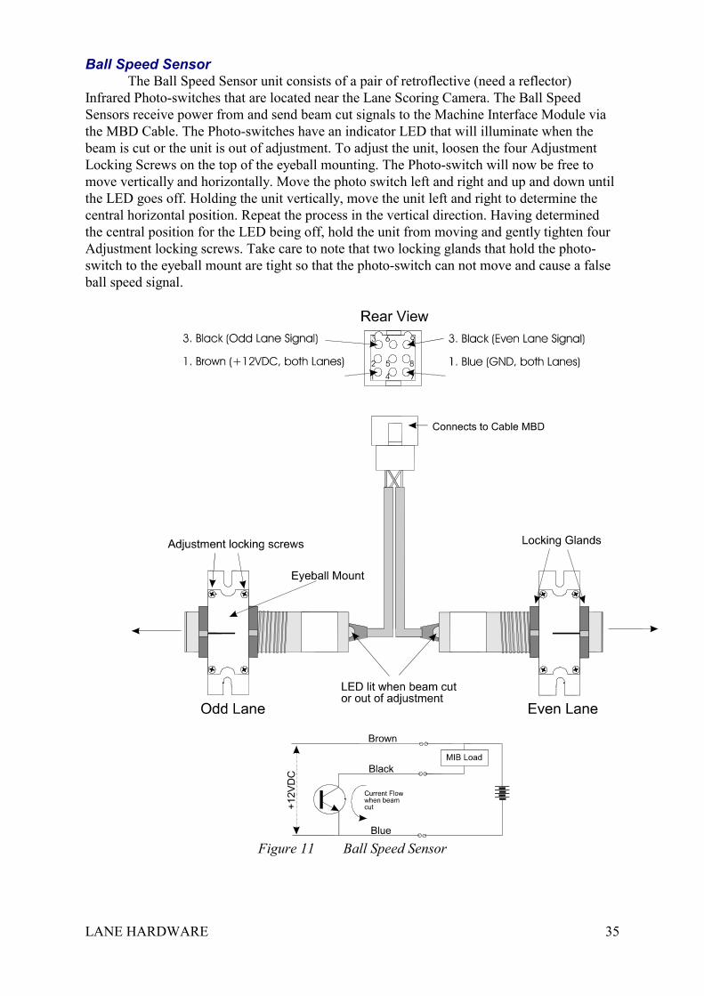
Ball Speed SensorThe Ball Speed Sensor unit consists of a pair of retroflective (need a reflector)
Infrared Photo-switches that are located near the Lane Scoring Camera. The Ball SpeedSensors receive power from and send beam cut signals to the Machine Interface Module viathe MBD Cable. The Photo-switches have an indicator LED that will illuminate when thebeam is cut or the unit is out of adjustment. To adjust the unit, loosen the four AdjustmentLocking Screws on the top of the eyeball mounting. The Photo-switch will now be free tomove vertically and horizontally. Move the photo switch left and right and up and down untilthe LED goes off. Holding the unit vertically, move the unit left and right to determine thecentral horizontal position. Repeat the process in the vertical direction. Having determinedthe central position for the LED being off, hold the unit from moving and gently tighten fourAdjustment locking screws. Take care to note that two locking glands that hold the photo-switch to the eyeball mount are tight so that the photo-switch can not move and cause a falseball speed signal.
Figure 11 Ball Speed Sensor
LANE HARDWARE 36
Safety Precautions & Hardware Disclaimer• Always ensure that the system has been installed and electrically wired in accordance to all
relevant safety codes by authorised electrical contractors. The Matrix chassis enclosure hasUL approval as do the SVGA Monitors. For protection from Electric Shock ensure that allmetal parts are adequately grounded.
• The SVGA monitors operate on High Voltage. The rear cover to the SVGA monitorsshould only be removed with both SVGA monitors off and with all Plugs removed fromtheir Outlets. The covers should be removed only by authorised service personnel. Themonitors serviced by authorised Service Personnel according to the monitor manufacturerService and Safety Procedures. When replacing a SVGA monitor always ensure that theground point of the replacement unit is securely grounded to the display unit ground point.Refer to the monitor manufacturer Service manual for safety precautions. Computer Scoreaccepts no liability for the Safety of the SVGA monitors.
• Under no circumstances operate the display units with the rear monitor covers removedwhile in the presence of the general public or any unauthorised personnel. Always cleanthe approach surface of the lanes after servicing the Display units or Keyboard Module sono dust or other material can cause a fall or endanger the public.
• The Matrix chassis contains no user serviceable parts and all service to the Matrix chassis,other than replacing the unit, is to be done by approved VanTech Comscore agents.Turning off the Matrix chassis using the power switch located on the chassis itself onlyturns off the Matrix chassis. It does not turn off the SVGA monitors.
• Unless installation was done by Computer Score. Computer Score accepts noresponsibility for the Safety of the system regarding physical security of installationmounting etc.
• Never use the Lane Scoring Camera as a handle when moving its support shaft.• The Machine Start Relay Contacts are only to be installed so that the
Pinsetting/Pinspotting Machine is still able to be turned off immediately at a convenientlocation at the control counter and the machine in case of emergency. This will usuallyinvolve wiring the contacts in Series (not parallel) with the existing managers controlswitches. An open Machine Contact is under no circumstances to be considered adequateprotection from the machine starting unexpectedly. The tenth frame cycle feature (ifconnected by the Centre Technician) results in the machine being cycled at possibly anytime without a ball being bowled. Under no circumstances should a Pinsetter/PinspotterMachine be entered while operating. Never enter a Pinsetter/Pinspotter unless it isswitched off at the power. Never rely on the Computer Score Machine Contact as it maybe operated without warning. Computer Score accepts no responsibility or liability for theSafety or Operation of any brand of Pinspotter/Pinsetter Machines or associated equipmentor the actions of anyone regarding this equipment. The Machine Start, Tenth Frame Cycleand Strike relay contacts are for low voltage only. Do not connect any of the MachineInterface Module Inputs or Outputs to, or near high voltage.
• The ball speed sensor input option of the Machine Interface Module is only used by thescoring system to determine ball speed and to differentiate between valid scores andinvalid scores. Cycling of the Pinsetter/Pinspotter Machine in the case of a light ball is theresponsibility of a separate program supplied by Ebonite-Vantage. Computer Score doesnot implement, recommend or require this feature for the operation of the Scoring System.(Refer the previous section Hardware Overview - Ball Speed Sensing). Refer to Ebonite-Vantage for any information regarding the VanTechTrigger program.
LANE HARDWARE 37
Hardware Issues
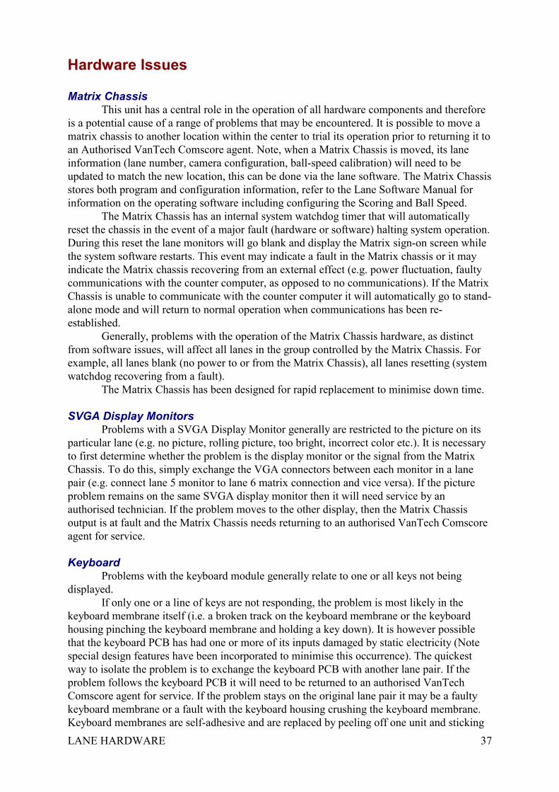
Matrix ChassisThis unit has a central role in the operation of all hardware components and therefore
is a potential cause of a range of problems that may be encountered. It is possible to move amatrix chassis to another location within the center to trial its operation prior to returning it toan Authorised VanTech Comscore agent. Note, when a Matrix Chassis is moved, its laneinformation (lane number, camera configuration, ball-speed calibration) will need to beupdated to match the new location, this can be done via the lane software. The Matrix Chassisstores both program and configuration information, refer to the Lane Software Manual forinformation on the operating software including configuring the Scoring and Ball Speed.
The Matrix Chassis has an internal system watchdog timer that will automaticallyreset the chassis in the event of a major fault (hardware or software) halting system operation.During this reset the lane monitors will go blank and display the Matrix sign-on screen whilethe system software restarts. This event may indicate a fault in the Matrix chassis or it mayindicate the Matrix chassis recovering from an external effect (e.g. power fluctuation, faultycommunications with the counter computer, as opposed to no communications). If the MatrixChassis is unable to communicate with the counter computer it will automatically go to stand-alone mode and will return to normal operation when communications has been re-established.
Generally, problems with the operation of the Matrix Chassis hardware, as distinctfrom software issues, will affect all lanes in the group controlled by the Matrix Chassis. Forexample, all lanes blank (no power to or from the Matrix Chassis), all lanes resetting (systemwatchdog recovering from a fault).
The Matrix Chassis has been designed for rapid replacement to minimise down time.
SVGA Display MonitorsProblems with a SVGA Display Monitor generally are restricted to the picture on its
particular lane (e.g. no picture, rolling picture, too bright, incorrect color etc.). It is necessaryto first determine whether the problem is the display monitor or the signal from the MatrixChassis. To do this, simply exchange the VGA connectors between each monitor in a lanepair (e.g. connect lane 5 monitor to lane 6 matrix connection and vice versa). If the pictureproblem remains on the same SVGA display monitor then it will need service by anauthorised technician. If the problem moves to the other display, then the Matrix Chassisoutput is at fault and the Matrix Chassis needs returning to an authorised VanTech Comscoreagent for service.
KeyboardProblems with the keyboard module generally relate to one or all keys not being
displayed. If only one or a line of keys are not responding, the problem is most likely in thekeyboard membrane itself (i.e. a broken track on the keyboard membrane or the keyboardhousing pinching the keyboard membrane and holding a key down). It is however possiblethat the keyboard PCB has had one or more of its inputs damaged by static electricity (Notespecial design features have been incorporated to minimise this occurrence). The quickestway to isolate the problem is to exchange the keyboard PCB with another lane pair. If theproblem follows the keyboard PCB it will need to be returned to an authorised VanTechComscore agent for service. If the problem stays on the original lane pair it may be a faultykeyboard membrane or a fault with the keyboard housing crushing the keyboard membrane.Keyboard membranes are self-adhesive and are replaced by peeling off one unit and sticking
LANE HARDWARE 38
down another. Note that a keyboard membrane that has been peeled off is usually unable to bere-used.
If no keys respond, the problem is generally not due to keyboard membrane. Keyboardpower and information travels from the Machine Interface Module at the curtain wall to theKeyboard Module via the MKM Cable. If the problem exists on more than one keyboard pairsin the Matrix Chassis group or other Machine Interface Module functions are not operating(e.g. Machine Cycle, Start or Ball Speed), then refer to the Machine Interface Module section.If not, the problem will be either with the Keyboard PCB or the MKM Cables. Listen for thekeyboard buzzer and check the indicator LEDs when a key is pressed. Also check if thekeyboard beeps three times on start up. Exchange the Keyboard PCB with another lane pair, ifthe problem follows the Keyboard PCB then it needs to be returned to an authorised VantechComscore agent for repair. If the problem stays with the lane pair than damage to the MKMCable is the most likely cause.
In the case of an Individual Keyboard configuration, The Slave module transmits itskey information to the Master module via the MKK Cable. The LED on the Master modulewill flash to indicate a key press on the slave module. It would be possible for a faulty masterunit or MKK cable to cause no keyboard response from the slave module.
Voltage free contact (switch closure) style foul units can be connected to the keyboardmodule Foul Connector. Most of these foul units have an isolated pair of contacts for odd andeven lane (four wires). Some units, however, one side of each contact connected together incommon (sometimes three or sometimes four wires). The Keyboard PCB Foul Connector pins1 and 3 are connected to ground inside the Keyboard PCB. In the case of voltage free contactswith a common pair, the common wire(s) need to be connected to pins 1 and(or) 3 of the FoulConnector.
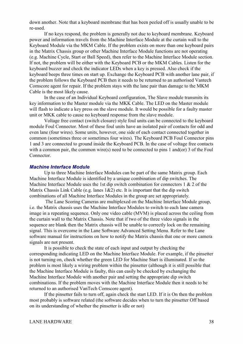
Machine Interface ModuIeUp to three Machine Interface Modules can be part of the same Matrix group. Each
Machine Interface Module is identified by a unique combination of dip switches. TheMachine Interface Module uses the 1st dip switch combination for connectors 1 & 2 of theMatrix Chassis Link Cable (e.g. lanes 1&2) etc. It is important that the dip switchcombinations of all Machine Interface Modules in the group are set appropriately.
The Lane Scoring Cameras are multiplexed on the Machine Interface Module group,i.e. the Matrix chassis uses the Machine Interface Modules to switch to each lane cameraimage in a repeating sequence. Only one video cable (MVM) is placed across the ceiling fromthe curtain wall to the Matrix Chassis. Note that if two of the three video signals in thesequence are blank then the Matrix chassis will be unable to correctly lock on the remainingsignal. This is overcome in the Lane Software Advanced Setting Menu. Refer to the Lanesoftware manual for instructions on how to notify the Matrix chassis that one or more camerasignals are not present.
It is possible to check the state of each input and output by checking thecorresponding indicating LED on the Machine Interface Module. For example, if the pinsetteris not turning on, check whether the green LED for Machine Start is illuminated. If so theproblem is most likely a wiring problem within the pinsetter (although it is still possible thatthe Machine Interface Module is faulty, this can easily be checked by exchanging theMachine Interface Module with another pair and setting the appropriate dip switchcombinations. If the problem moves with the Machine Interface Module then it needs to bereturned to an authorised VanTech Comscore agent).
If the pinsetter fails to turn off, again check the start LED. If it is On then the problemmost probably is software related (the software decides when to turn the pinsetter Off basedon its understanding of whether the pinsetter is idle or not)
LANE HARDWARE 39
If the Machine Interface Module is suspected of causing false pinsetter cycles, checkthe green cycle LED. If it does not illuminate, the problem is most likely a pinsetter problem.It is possible to completely remove the pinsetter cycle connection to the Machine InterfaceModule connector to ultimately prove whether the scoring system is a fault in such a case.
Each of the Machine Interface Module output contacts have a 900mA resettablethermal fuse in series for protection. If excessive current flows through the contact, thethermal fuse will halt current flow to avoid damage to the Machine Interface Module.
If none of the Machine Interface Modules in the Matrix group are operating, theproblem may be related to the Matrix chassis or the cables (MCM, MVM or MPM). Powerfor the Machine Interface Modules in the group comes from the Display Unit via the MPMcable. This includes power to the Keyboard Modules.
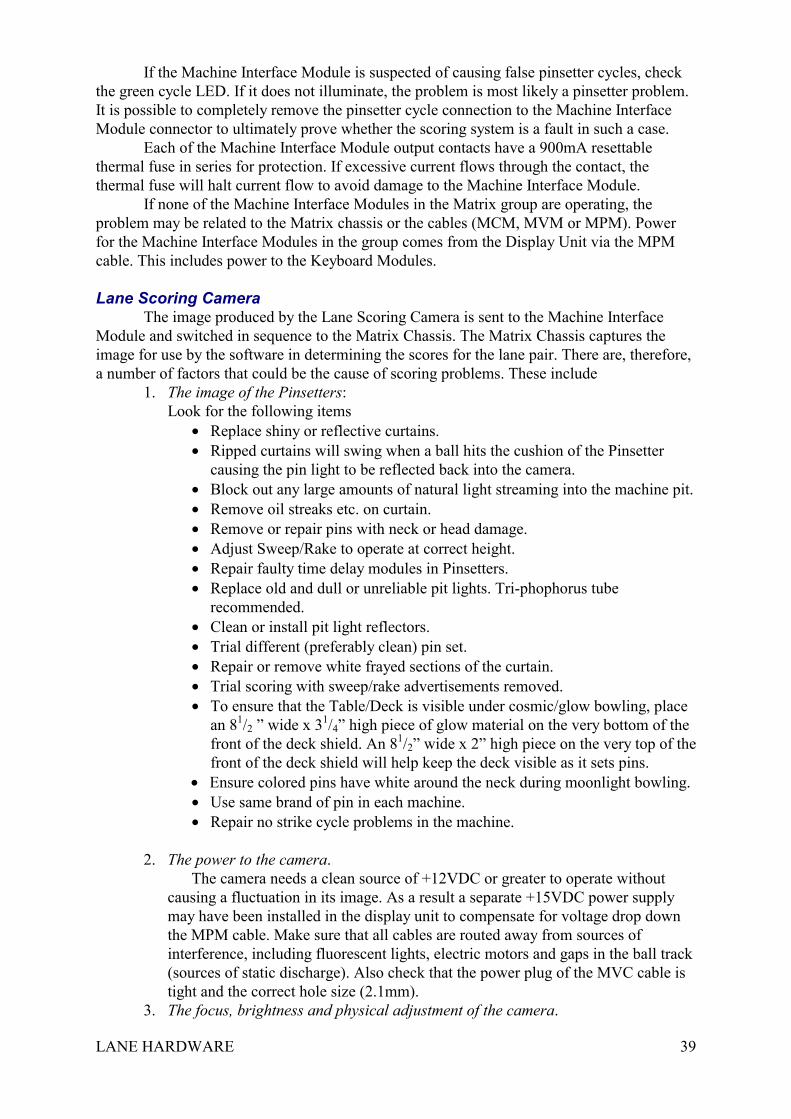
Lane Scoring CameraThe image produced by the Lane Scoring Camera is sent to the Machine Interface
Module and switched in sequence to the Matrix Chassis. The Matrix Chassis captures theimage for use by the software in determining the scores for the lane pair. There are, therefore,a number of factors that could be the cause of scoring problems. These include
1. The image of the Pinsetters:Look for the following items
• Replace shiny or reflective curtains.• Ripped curtains will swing when a ball hits the cushion of the Pinsetter
causing the pin light to be reflected back into the camera.• Block out any large amounts of natural light streaming into the machine pit.• Remove oil streaks etc. on curtain.• Remove or repair pins with neck or head damage.• Adjust Sweep/Rake to operate at correct height.• Repair faulty time delay modules in Pinsetters.• Replace old and dull or unreliable pit lights. Tri-phophorus tube
recommended.• Clean or install pit light reflectors.• Trial different (preferably clean) pin set.• Repair or remove white frayed sections of the curtain.• Trial scoring with sweep/rake advertisements removed.• To ensure that the Table/Deck is visible under cosmic/glow bowling, place
an 81/2 ” wide x 31/4” high piece of glow material on the very bottom of thefront of the deck shield. An 81/2” wide x 2” high piece on the very top of thefront of the deck shield will help keep the deck visible as it sets pins.
• Ensure colored pins have white around the neck during moonlight bowling.• Use same brand of pin in each machine.• Repair no strike cycle problems in the machine.
2. The power to the camera.The camera needs a clean source of +12VDC or greater to operate without
causing a fluctuation in its image. As a result a separate +15VDC power supplymay have been installed in the display unit to compensate for voltage drop downthe MPM cable. Make sure that all cables are routed away from sources ofinterference, including fluorescent lights, electric motors and gaps in the ball track(sources of static discharge). Also check that the power plug of the MVC cable istight and the correct hole size (2.1mm).
3. The focus, brightness and physical adjustment of the camera.
LANE HARDWARE 40
All cameras have factory set focus and iris (brightness) adjustments. Theseadjustments are locked in place at the camera lens using two fine screws. If thecamera image appears out of focus on the camera set up menu, it is possible toloosen these screws and manually adjust focus and brightness. It is stronglyadvised that such adjustment should only be undertaken in consultation with anauthorised VanTech Comscore agent. Also, excessive vibration of the camera maylead to loosening of the camera’s lens or casing screws.
Although the Lane Scoring Software configuration process is designed toautomatically determine the position of all the pins on the lane pair, the systembenefits from a correctly positioned camera. The most critical physical adjustmentis the tilt across the lane pair, i.e. make sure the image of the camera appearshorizontal with the pins of the odd lane being at the same height as the even lane.The pins should be approximately in the centre of the image both vertically andhorizontally. Make sure that the camera is locked onto its support pedestal via alocking bolt and star washer. Check that the mounting lags are secured properly tothe sub-frame and that the sub-frame is secure. Check that the capping does nottouch the mounting pole and that the camera shield does not touch the camera.
4. The camera’s hardwareInspection of the captured camera image on the Camera Set-up Menu, may
reveal a blank, rolling or fluctuating image from the Camera. If so it is advisedthat the camera be swapped with another to check if the problem follows thecamera.
5. The cables leading to the Machine Interface ModuleAs per the above, if the problem stays on the original lane pair, the cables will
need inspection for potential breaks or damage (particularly cables resting on theball track or being squashed by part of the machine).
6. The Machine Interface Module’s hardware and the cables leading to the MatrixChassis.
Refer Issues in the Machine Interface Module section.7. The Matrix Chassis hardware and software.
Refer Issues in the Matrix Chassis section as well as the Lane Software manualregarding Camera Setup Menu.
Ball Speed SensorsIf Ball Detection is enabled in the Options Menu for the lane pair and the system fails
to be notified of a ball being bowled, then the system will not register the score. This featureis very useful in eliminating unwanted score corrections from pin stands etc. but will cause aproblem if the ball speed sensor is mis-aligned or malfunctioning. The photo-switches havean LED to indicate when the beam has been cut. If this LED is continuously on, then re alignthe photo-switch. If the photo-switch is unable to be placed in a position where the LED isoff, then the unit may be faulty, the reflector may be mis-aligned or photo-switch voltage maybe low (this can be a cabling, Machine Interface Module or power supply problem).
If the LED comes on as the beam is cut but the system is still not scoring, check theLED indicator on the Machine Interface Module. This LED indicator should also illuminatewhen the beam is cut. If it does not, the problem may be in the cabling to the MachineInterface Module, be a faulty Machine Interface Module or may be an internal fault in thephoto-switch. Check the MBD cable for breakage or crushing, particularly over the ball trackor around the pinsetter.
It is possible to disable the Ball Detection feature in the Lane Software Options Menu,the scoring will still function but all pinsetter cycles will generate a score. This is a rapid way

LANE HARDWARE 41
of determining if the ball detection is the cause of the no score and also allows bowling tocontinue until such a time that the lanes are available.
Refer to the Lane Software Manual for calibrating ball speed.Note that there are many different types of photo-switches. The type used for this
application are described as retroflective, NPN transistor output, Dark On.