Embed Size (px)
Citation preview
NISTIR 8059
Materials Testing
Standards for Additive
Manufacturing of Polymer
Materials: State of the Art and Standards Applicability Aaron M. Forster
NISTIR 8059
Materials Testing Standards for Additive Manufacturing of Polymer
Materials: State of the Art and Standards Applicability
Aaron M. Forster
This publication is available free of charge from:
http://dx.doi.org/10.6028/NIST.IR.8059
NISTIR 8059
Materials Testing Standards for Additive Manufacturing of Polymer
Materials: State of the Art and Standards Applicability
Aaron M. Forster
Materials and Structural Systems Division Engineering Laboratory
This publication is available free of charge from: http://dx.doi.org/10.6028/NIST.IR.8059
May 2015
U.S. Department of Commerce
Penny Pritzker, Secretary
National Institute of Standards and Technology Willie May, Under Secretary of Commerce for Standards and Technology and Director

National Institute of Standards and Technology Interagency Report 8059 54 pages (May 2015)
This publication is available free of charge from: http://dx.doi.org/10.6028/NIST.IR.8059
Comments on this publication may be sent to:
National Institute of Standards and Technology Attn: Computer Security Division, Information Technology Laboratory
100 Bureau Drive (Mail Stop 8930) Gaithersburg, MD 20899-8930
Certain commercial entities, equipment, or materials may be identified in this document in order to
describe an experimental procedure or concept adequately. Such identification is not intended to imply
recommendation or endorsement by NIST, nor is it intended to imply that the entities, materials, or
equipment are necessarily the best available for the purpose.
There may be references in this publication to other publications currently under development by NIST
in accordance with its assigned statutory responsibilities. The information in this publication, including
concepts and methodologies, may be used by Federal agencies even before the completion of such
companion publications. Thus, until each publication is completed, current requirements, guidelines,
and procedures, where they exist, remain operative. For planning and transition purposes, Federal
agencies may wish to closely follow the development of these new publications by NIST.
Organizations are encouraged to review all draft publications during public comment periods and
provide feedback to NIST. All NIST Computer Security Division publications, other than the ones
noted above, are available at http://csrc.nist.gov/publications.
i
Abstract
Additive manufacturing (AM) continues to grow as an advanced manufacturing technique. The
most recent industry report from Wohlers and Associates indicates AM represented $1.6B in
revenue from parts, systems, and other supporting industries in 2012 and is expected to grow to
more than $3.5B by 2017 and to $10B by 2022. The measurement challenges for AM, whether
the deposited material is metal or polymer, are similar. Parallels between the additive
manufacturing for metals and polymers include: characterization of raw materials, development
of material properties for design, in-situ process and feedback control, workflow optimization,
and modeling final properties. The scope of this report is to analyze the current trends in polymer
additive manufacturing and determine the applicability of current American Society for Testing
Materials International (ASTM) and the International Standards Organization (ISO) standard test
methods for mechanical properties and failure of polymers and polymer composites generated
from the additive manufacturing processes. The current approach to mechanical testing standards
utilizes existing guidelines for testing materials, but this analysis highlights the need to develop
specific guidelines for testing AM materials. The current AM efforts at NIST towards polymers
are supported through the Material Measurement Laboratory (MML) AM program. While this
program is addressing critical measurement science to validate polymer physics within AM, it is
not directly translating this knowledge into the standards required for engineering design. The
emerging engineering and standards challenges for high performance polymers and polymer
composites are not currently addressed by the Engineering Laboratory (EL) Additive
Manufacturing program, which is focused on metal applications. The development of a program
to bridge the measurement gap between molecular architecture of AM materials (MML) and
generating engineering properties for design represents an opportunity for the EL effort.
Key words: additive manufacturing, polymer, mechanical properties, standards, testing
ii
Table of Contents
Table of Figures ............................................................................................................................. iii
List of Acronyms ........................................................................................................................... iv
1. Introduction: ............................................................................................................................ 1
2. Scope: ...................................................................................................................................... 3
3. Government and Academic Support: ...................................................................................... 4
4. Materials: ................................................................................................................................. 6
5. Mechanical Properties for Design: .......................................................................................... 9
6. Challenges for Mechanical Property Characterization: ......................................................... 15
7. Overview of Standard Testing Methods ................................................................................ 19
7.1. Tension ........................................................................................................................... 19
7.2. Flexure ............................................................................................................................ 19
7.3. Compression ................................................................................................................... 20
7.4. Shear ............................................................................................................................... 20
7.5. Creep .............................................................................................................................. 20
7.6. Fatigue ............................................................................................................................ 21
7.7. Fracture Toughness ........................................................................................................ 21
7.8. Impact ............................................................................................................................. 22
7.9. Bearing Strength and Open Hole Compression ............................................................. 23
8. Standards Applicability Assessment ..................................................................................... 23
9. Polymer Additive Manufacturing at NIST ............................................................................ 32
10. Conclusion and Path Forward................................................................................................ 33
Acknowledgements ....................................................................................................................... 35
References ..................................................................................................................................... 36
iii
Table of Figures
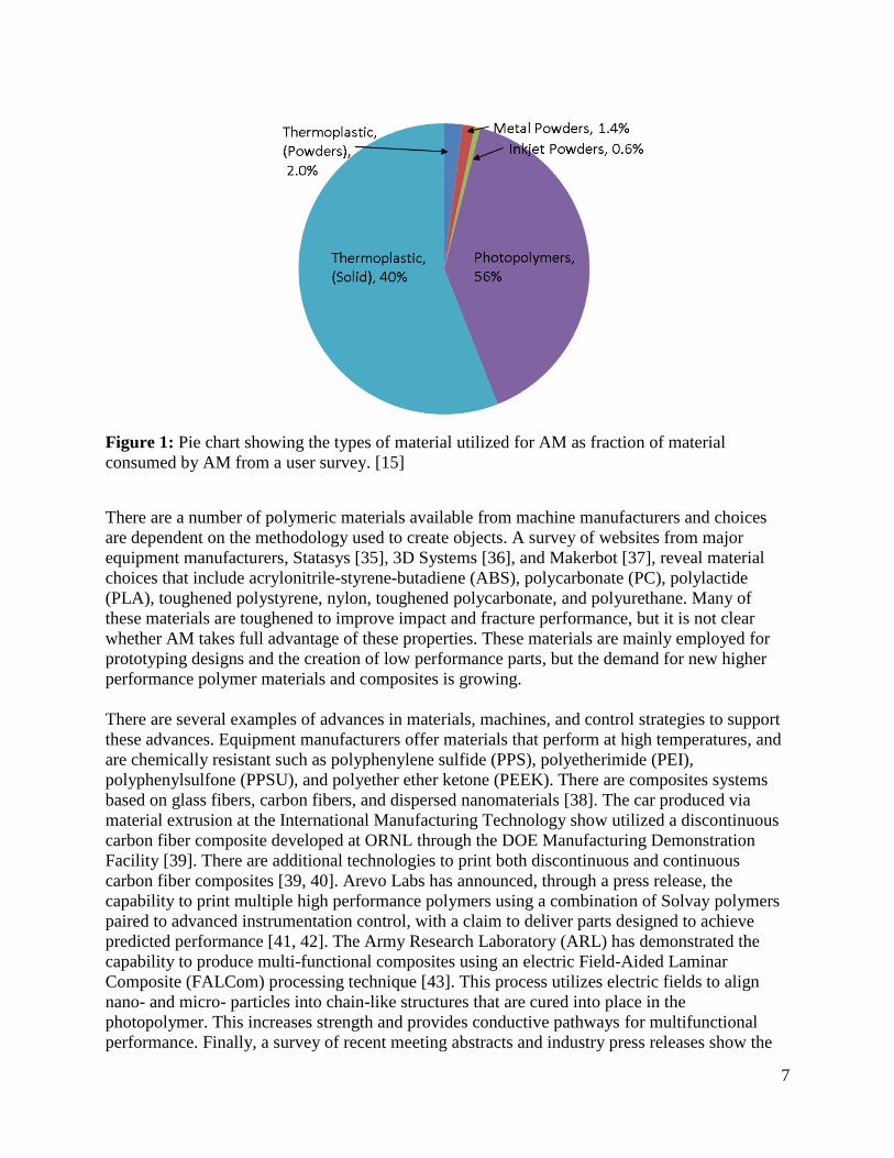
Figure 1: Pie chart showing the types of material utilized for AM as fraction of material
consumed by AM from a user survey. [15] .................................................................................... 7
Figure 2: Building block integration for the development of composite structures [53].............. 10
Figure 3: Building block approach for the support of composites structures in the 777 aircraft
[53]. In this graphic durability is defined through moisture stability, temperature stability, creep
resistance, and fatigue resistance. ................................................................................................. 11
Figure 4: Mesostructure of an ME-ABS material illustrating the porous structure that may be
achieved based on the raster angle and bead overlap [54]. ........................................................... 12
Figure 5: Graphic illustrating the directionality of fibers, through z, in a fiber composite
laminate. The orientation and number of fibers controls the performance of the composite. ...... 13
Figure 6: Three modes of crack surface displacements Mode I (opening or tensile mode), Mode
II (sliding mode), and Mode III (tearing mode) copied from [56]. ............................................... 14
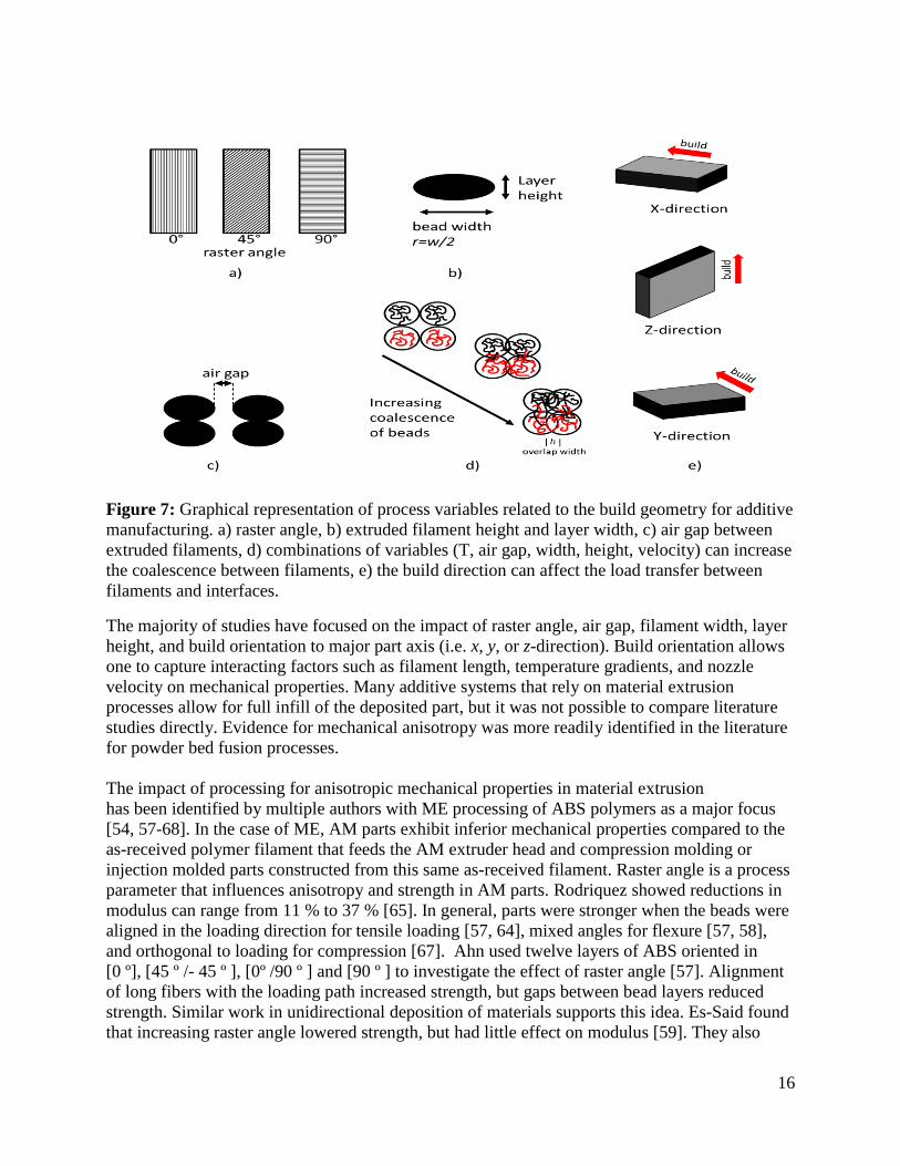
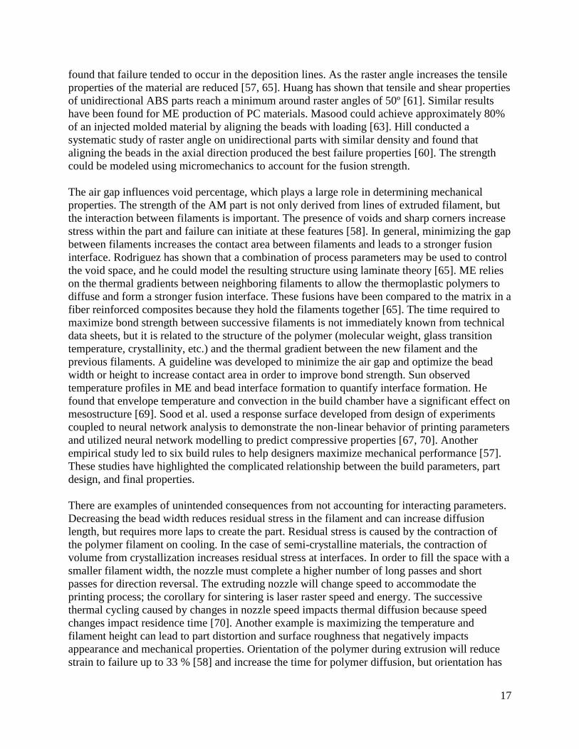
Figure 7: Graphical representation of process variables related to the build geometry for additive
manufacturing. a) raster angle, b) extruded filament height and layer width, c) air gap between
extruded filaments, d) combinations of variables (T, air gap, width, height, velocity) can increase
the coalescence between filaments, e) the build direction can affect the load transfer between
filaments and interfaces. ............................................................................................................... 16
iv
List of Acronyms
AMC, Additive Manufacturing Consortium – A national consortium of industry, government,
academic, and non-profit research organizations with the mission of accelerating and advancing
the manufacturing readiness of metal additive manufacturing technology.
AM, additive manufacturing – a process of joining materials to make objects from 3D model
data, usually layer upon layer, as opposed to subtractive manufacturing methodologies [1].
AmericaMakes – is the National Additive Manufacturing Innovation Institute. AmericaMakes is
focused on helping the United States grow capabilities and strength in 3D printing. It is based in
Youngstown, Ohio and is an extensive network of more than 100 companies, non-profit
organizations, academic institutions and government agencies [2].
ARL - Army Research Laboratory.
ASTM – American Society of Testing Materials International.
Battelle – Battelle Memorial Institute is the world’s largest nonprofit research and development
organization.
CAD/CAM – Computer Aided Design/Computer Aided Machining.
CAMM, Consortium for Additive Manufacturing Materials – The organizational component
of CIMP 3D. It was created from a NIST Advanced Manufacturing Technology Consortia
(AMTech) Program grant to foster innovation in additive manufacturing.
CIMP 3D, Center for Innovative Materials Processing Through Direct Digital Deposition –
A consortium administered by Pennsylvania State University, Batelle, and Sciaky Corporation. It
is a resource for AM technology for critical applications [3].
CNC, computer numerical control – indicative of computer-controlled machinery for cutting
various hard materials. These are synonymous with subtractive manufacturing methods.
DARPA – Defense Advanced Research Projects Agency.
FDM – a material extrusion process used to make thermoplastic parts through heated extrusion
and deposition of materials layer by layer; term denotes machines built by Stratasys, Inc [1].
ISO – International Standards Organization.
LS, laser sintering – a powder bed fusion process used to produce objects from powdered
materials using one or more layers to selectively fuse or melt the particles at the surface, layer by
layer, in an enclosed chamber [1].

v
NAMII, National Additive Manufacturing Innovation Institute - The pilot institute from
NNMI established in 2012. This consortium includes 40 companies, nine research universities,
five community colleges, and 11 nonprofit organizations. This consortium is also called
AmericaMakes [4].
NCDMM, National Center for Defense Manufacturing and Machining – the driver of
AmericaMakes. The mission is to deliver optimized manufacturing solutions that enhance the
quality, affordability, maintainability, and rapid deployment of existing and yet-to-be developed
defense systems [5].
NNMI, National Network for Manufacturing Innovation – A federally backed network
established by the Revitalize American Manufacturing Act. The institutes developed under
NNMI are intended to create a competitive, effective, and sustainable manufacturing research-to-
manufacturing infrastructure for U.S. industry and academia to solve industry-relevant problems.
ME, material extrusion – an additive manufacturing process in which a material is selectively
dispensed through a nozzle or orifice [1].
MSAM, Measurement Science for Advanced Manufacturing – A cooperative agreement
program that solicits proposals for grants to advanced manufacturing. The program is
administered by the National Institutes of Standards and Technology. This is the program
developed to administer grants for the NNMI.
ONR – Office of Naval Research
ORNL – Oak Ridge National Laboratory
1
1. Introduction1:
Additive manufacturing is a process of joining materials to make objects from 3D model data,
usually in a layer by layer process [1, 6]. The objects are created in CAD/CAM software,
transformed to machining instructions similar to the process for CNC machining, and each layer
is directly fabricated on top of previous layers to create a replica of the object. In general, this
manufacturing process is not subtractive. Multiple processes exist to create polymeric materials
and composites, but they generally fall into three classes: material extrusion, powder bed fusion,
and material jetting.
Material Extrusion (ME) is a process that selectively dispenses a thermoplastic polymer through
a nozzle. Stratasys has trademarked the term fused deposition modeling (FDM®) to identify their
systems that utilize this technique [1]. The extrusion head melts the plastic filament, extrudes
material through a nozzle, and places the resin bead onto the substrate. This is a less aggressive
process compared to injection molding where the plastic is melted and uniformly blended using a
screw extruder to inject the material at high pressure into a mold. There are specific challenges
for additive manufacturing that are unique to polymeric materials. In ME, heat is used to melt a
polymer filament and the material is directed to a specific location via a nozzle. This places a
polymer beads or filament of a specific size and length onto the substrate. Successive beads are
layered to create the final 3D structure. The strength of the part is generated from the deposited
material properties and the interface between beads. The interface is important because the
neighboring beads are at a lower temperature than the molten bead leaving the nozzle. The
thermal gradient between the two materials will melt the existing bead and cause polymers
molecule to diffuse across the interface. The strength of this fusion is dependent on many factors
such as temperature gradient, polymer structure (molecular weight, branching, heat of fusion,
glass transition temperature, etc.), and bead geometry. It is possible for this fusion to exist under
stress prior to any mechanical loading. As the beads cool, the polymer contracts which creates a
localized residual stress. As the performance of AM materials is increased by using semi-
crystalline and more rigid polymers, the physics to model interfacial strength and stress are
different than amorphous materials. There are additional challenges such as ME surface
roughness, void space between beads, and defects (excess material) that can initiate failure
modes within the part under loading. The nature of the printing process and the aligned structure
of the beads make AM parts highly anisotropic and this anisotropy may exhibit a non-linear
dependence on processing parameters.
Laser sintering (LS), or powder bed fusion, is a process that utilizes directed energy to melt a
thermoplastic powder similar to the process used to generate parts from metal powders. This
process starts with a powder bed of polymer powder of a specific layer height and temperature.
A high powered laser is rastered across the surface to locally heat the polymer pellets. At this
1 Certain commercial equipment, instruments, or materials are identified in this paper to
foster understanding. Such identification does not imply recommendation or endorsement by
the National Institute of Standards and Technology, nor does it imply that the materials or
equipment identified are necessarily the best available for the purpose.
2
point, two thermal processes could occur depending on the machine design. The laser could fully
melt the polymer pellets and allow the molten material to flow and diffuse into adjacent material.
The second process locally heats the pellets to allow diffusion of polymer between adjacent
pellets and layers. This is equivalent to a sintering process. In either case, the locally heated
polymer diffuses to create a single layer within the part. A fresh layer of powder material is
placed on top of the previous layer and the laser again melts local regions of polymer. The
strength of parts is dependent on the ability of the process to manage thermal gradients. The
molten material must flow into cracks adjacent to previous layers and the thermal gradient must
be high enough to allow entanglement between neighboring polymer layers [7]. These parts tend
to exhibit anisotropy characteristic of the laser scanning direction or build (Z) direction and can
exhibit location dependent voids.
The material jetting process, which is similar to early stereolithography methods used for rapid
prototyping [8], utilizes an inkjet print head to deposit a thin layer of photopolymerizable
polymer and initiator. Ultraviolet lamps, or similar energy source, at the print head initiate cure
of the photopolymer layer as it is deposited [9]. Direct printing processes have challenges related
to the chemistry of the photocurable polymers used to build parts. Localized curing may be
inhomogeneous which leads to a range of mechanical properties throughout the part.
Uncrosslinked material trapped within holes may plasticize or age the part causing premature
failure [10].
Additive manufacturing (AM) continues to grow as an advanced manufacturing technique. The
most recent industry report from Wohlers and Associates indicates AM represented $1.6B in
revenue from parts, systems, and other supporting industries in 2012 [11] and is expected to
grow to more than $3.5B by 2017 [12] and to $10B by 2022 [13]. The AM material market is
expected to grow from $470M in 2013 to over $1.09B in 2022 [13]. Industry, government and
academia in the U.S. have been working to support the rate of growth by expanding machine
capabilities and developing new high strength and biomedical materials. A report by IDTechEx
as reported in The Guardian indicates the dental and medical market is expected to expand to
$867M by 2025, the inclusion of additively manufactured organs and tissues would mean a
potential of $6B within 10 years [14, 15].
Currently, there are few standards specifically addressing mechanical properties of AM parts.
ASTM F42.01 has a number of standards and work items focused on metals AM [16]. There is
currently one ASTM standard test method applicable to powder bed fusion of plastic materials;
F3091/F3019M-14 Standard Specification for Powder Bed Fusion of Plastic Materials [17]. The
subcommittee has one work item that covers evaluation of manufacturing systems: WK 40419
New Test Methods for Performance evaluation of additive manufacturing systems through
measurement of a manufactured test piece [18]. The International Standards Organization (ISO)
has one active standard: ISO 17296-3:2014 Additive Manufacturing – General Principles—Part
3: Main characteristics and corresponding test methods [19] to address quality characteristics of
parts produced by AM. This standard references other ISO standards for mechanical property
testing of polymers and metals, but there are no AM specific considerations in testing. The lack
of AM specific mechanical standards creates challenges for stakeholders to provide equal
comparisons between machines, materials, and models that predict final part properties in order
3
to generate design allowables. Stahl has identified the inferior mechanical performance
compared to that for traditionally manufactured parts as a risk for AM [20].
2. Scope:
The measurement challenges for AM, whether it is metal or polymer, are similar. Parallels
between the material systems include: characterization of raw materials, development of design
allowables, in-situ process and feedback control, workflow optimization, and modeling final
properties [21]. The emerging engineering and standards challenges for high performance
polymers and polymer composites are not directly addressed by the Engineering Laboratory
Additive Manufacturing program, which is focused on metal applications. The scope of this
report is to analyze the current trends in polymer additive manufacturing and determine the
applicability of current ASTM and the ISO standard test methods for mechanical properties and
failure of polymers and polymer composites generated from the additive manufacturing
processes.
This report follows the style of previous NIST Internal Reports (NISTIR), NISTIR 8005 [22] and
NISTIR 7847 [23], from EL to document the standards needs in metal AM. This report will
provide:
a. State of the art for additive manufacturing of polymers and polymer composites
b. Analysis of the technical hurdles that are preventing these materials from high
performance manufacturing applications.
c. Analysis of the current ASTM and ISO standards for measuring mechanical
properties and failure of polymers and composites to include:
i. Standard designation,
ii. Standard Name,
iii. Application to AM testing,
iv. Notes concerning each standard relevant to the AM,
d. Summary of recommended potential directions for NIST standards research in
polymer additive manufacturing.
This report will also describe the emerging effort in the Material Measurement Laboratory
(MML) to support polymer additive manufacturing efforts and the potential opportunities for
leveraging collaborative efforts between MML and the Engineering Laboratory. In order to limit
the scope of this effort, concessions were made to focus on materials, measurement length scales,
and types of standards as described below:
• Polymers– Standardized methods for measuring the mechanical properties polymeric materials
utilized in ME, laser sintering, and direct printing were addressed. Mechanical property
measurement standards for polymer matrix fiber reinforced composites were also included for
review. Fiber reinforced composites use a polymer matrix to support woven or aligned high
strength fibers. Manufacturing composites requires stacking multiple layers of fibers and
infusing the interstitial spacing with a polymer resin. The fibers are strong in the axial direction
4
and weaker in the radial direction; the fibers provide anisotropy to the strength of the composite.
Therefore, standardized measurements developed for mechanical properties in fiber reinforced
composites may be applicable to additively manufactured materials.
• Bulk Mechanical Properties – Standardized methods for bulk property measurements were
addressed. Mechanical property measurements of localized properties, like those obtained by
micro-indentation, hardness, and atomic force microscopy were excluded.
• Focus on International Standards – This was done in order to make the assessment practical. A
cursory review of standards from the major Standards Development Organizations showed that
ASTM and ISO mechanical testing standards are representative of all the pertinent standardized
mechanical testing methods. A number of industry groups have developed protocols for
reference tests. These tests are useful and some eventually become standards. Such tests are
not covered here for three reasons: there are many such tests, often they are specific to an
industry sector or product, and many are consensus methods that may lack the rigorous
scientific basis and round-robin verification that is required for a standard.
3. Government and Academic Support:
In 2009 the National Science Foundation (NSF) developed a Roadmap for Additive
Manufacturing [24]. This roadmap addressed various challenges faced by the industry in the
areas of design, materials, biomaterials, and energy and sustainability. The main
recommendations from this roadmap were to:
expand the capabilities of solid modeling to support additive manufacturing,
develop better closed loop and feedback control,
develop predictive process-structure-property relationships integrated into CAD/CAM
tools,
improve physical models of AM processes to maximize the properties of AM parts,
develop and adopt internationally recognized standards which are useful to product,
process, and material certification
Chapter 6 of this report highlights the types of material properties that are measured to
determine the engineering properties used to design structures. In addition, understanding the
anisotropy of AM parts allows specific functionality to be built into the manufacturing process
and this allows unique capabilities not achievable through other manufacturing methods. NSF
funded additive manufacturing to a total of $200M from 1986 to 2012 [24].
In 2012 the creation of the National Network for Manufacturing Innovation (NNMI) was started
by the Executive Office of the President to develop regional advanced manufacturing hubs [4].
One of the first hubs was AmericaMakes. AmericaMakes is a partnership among the
Departments of Commerce, Defense, Energy, NASA, and NSF. This effort led to the funding of
the National Center for Defense Manufacturing and Machining (NCDMM) in Youngstown Ohio,
which brings together a regional network of 14 research universities, community colleges, 40
industry partners, and 10 non-profit organizations spanning Western Pennsylvania, Eastern Ohio,
and West Virginia. This effort is funded with a $40M private match to the initial $30M federal
5
investment. NIST’s Measurement Science for Advanced Manufacturing program (MSAM) has
funded NCDMM with $5M for research to ensure quality parts are produced from LS of metal
powders [25]. The NCDMM mission is to build a national network for additive manufacturing
and 3D printing technologies in the U.S. [5].
Currently, AmericaMakes is funding projects for ME processing of high-temperature
commercial polymers, ME for complex shape composite tooling, and AM manufactured
composite tooling for hydroforming. The University of Texas at El Paso has formed the
W.M. Keck Center for 3D Evaluation which has one project to develop integrated technologies
for multi-material structures [4]. In addition, materials characterization, quality control, data sets
for process-property validation, and tailored materials have been identified as critical topic areas
in both project calls from AmericaMakes.
Additive manufacturing has led to several centers of development within academia. The first
freeform manufacturing center was started in 1988 at The University of Texas at Austin.
Pennsylvania State University started the Center for Innovative Materials Processing through
Direct Digital Deposition (CIMP-3D) for metallic AM with the following government partners:
DARPA, ONR, and Battelle. This consortium is developing an advanced process modeling and
analysis framework for metal manufacturing. This framework includes incorporation of material
science principles (microstructure, kinetics, and thermodynamics) to predict and control the final
properties of the additive manufactured part. The Consortium for Additive Manufacturing
Materials (CAMM) was started in 2013 as part of the NIST AMTech program ($500K) and will
develop a comprehensive roadmapping effort for new types of additive materials [26]. The
American Lightweight Materials Innovation Institute is a partnership between the Edison
Welding Institute, The Ohio State University, and the University of Michigan. The University of
Connecticut has recently opened the Pratt & Whitney Additive Manufacturing Innovation Center
to focus on metals. The Michigan Technological University hosts the Open Sustainability
Technology Laboratory. This laboratory supports the development of open source software and
hardware for all forms of additive manufacturing. The goal is to make additive manufacturing
technology fully accessible to any user. North Carolina State University hosts the Center for
Additive Manufacturing and Logistics. Northern Illinois University was awarded $2.4M through
the NIST MSAM program to develop physics-based AM models for process control and quality
assurance [25]. Many of the academic efforts focus on the development of new materials,
improvement of existing materials, development of instrumentation and test methods, and
process material-property relationships for aerospace and biomedical applications. There is
overlap within projects, but they are directed at improving the AM process and final products.
Additive manufacturing has recently been demonstrated for more than small parts and devices.
Oak Ridge National Laboratory has partnered with Cincinnati Incorporated to develop a large-
scale polymer additive manufacturing system, with a goal of increasing speed by 500 times and
building components that are 10 times larger (> 1 m3) than typical AM parts [27, 28]. Local
Motors is a company that specializes in the development of large area additive manufacturing
machines. This company additively manufactured an automobile during the International
Manufacturing Technology Show within the exhibition hall [29]. They have recently opened an
office in the National Harbor area of Washington D.C.; the large scale printer and polymers used
for this demonstration were developed through collaborative research supported with ORNL.

6
Andrey Rudenko additively manufactured a 2-story concrete home in the shape of a castle out of
concrete [30]. While these applications remain a technical curiosity, they represent the desire to
push the industry to stronger materials and applications critical to life safety.
One of the advantages of additive manufacturing is the accessibility of the technology to
individuals, especially for soft materials. A large community of do-it-yourself consumers has
grown up to provide open source plans for building machines, control software, start new small
manufacturing businesses, and release of downloadable CAD drawings. The ease of technology
transfer has spurned innovations in manufacturing at all levels. The growth of sub-$5K
consumer-level printers is expected to increase [31]. Further information on advances in the open
source additive manufacturing market may be found at RepRap project [32] and Makerspace
[33] websites.
The significant investment in AM from public-private partnerships, entrepreneurs, and the
general public is expected to lead to new manufacturing technologies, better materials, and new
markets for AM. Engineers require science-based standards to support design and validate
mechanical performance. Machine manufacturers require methods to predict performance based
on processing parameters (e.g. extrusion temperature, extrusion nozzle shape, extrusion velocity,
etc.), which requires incorporation of polymer physics, constitutive equations, and improved
process control methodologies. Standards will be critical to supporting competitiveness as these
efforts mature to widely available manufactured products.
4. Materials:
Polymers are critical for AM because they represent the greatest market penetration and user
accessibility [31][32][33]. The importance of polymers to materials in this community has been
documented through a survey of “commons based peer production” of users available through
the web [34], where polymers represent the major source of printable materials. This was a
survey conducted within the open source community, mentioned earlier, to gauge their materials
and manufacturing needs. Figure 1 shows the breakdown of materials used in AM printing by
tonnage used in 2013. Photopolymers generated over $239M in market revenue and the market is
expected to reach $470M in 2022 [13]. Laser sintering equipment is not yet easily obtained by
most non-manufacturing consumers because of the cost of the equipment and the difficulties in
handling dispersible metal powders. Although polymers lag metals in the development of
structural mechanical properties, the potential to impact many more markets from consumer
products, sustainable applications, advanced manufacturing, and biomedical devices is far
greater for polymers [15].
7
Figure 1: Pie chart showing the types of material utilized for AM as fraction of material
consumed by AM from a user survey. [15]
There are a number of polymeric materials available from machine manufacturers and choices
are dependent on the methodology used to create objects. A survey of websites from major
equipment manufacturers, Statasys [35], 3D Systems [36], and Makerbot [37], reveal material
choices that include acrylonitrile-styrene-butadiene (ABS), polycarbonate (PC), polylactide
(PLA), toughened polystyrene, nylon, toughened polycarbonate, and polyurethane. Many of
these materials are toughened to improve impact and fracture performance, but it is not clear
whether AM takes full advantage of these properties. These materials are mainly employed for
prototyping designs and the creation of low performance parts, but the demand for new higher
performance polymer materials and composites is growing.
There are several examples of advances in materials, machines, and control strategies to support
these advances. Equipment manufacturers offer materials that perform at high temperatures, and
are chemically resistant such as polyphenylene sulfide (PPS), polyetherimide (PEI),
polyphenylsulfone (PPSU), and polyether ether ketone (PEEK). There are composites systems
based on glass fibers, carbon fibers, and dispersed nanomaterials [38]. The car produced via
material extrusion at the International Manufacturing Technology show utilized a discontinuous
carbon fiber composite developed at ORNL through the DOE Manufacturing Demonstration
Facility [39]. There are additional technologies to print both discontinuous and continuous
carbon fiber composites [39, 40]. Arevo Labs has announced, through a press release, the
capability to print multiple high performance polymers using a combination of Solvay polymers
paired to advanced instrumentation control, with a claim to deliver parts designed to achieve
predicted performance [41, 42]. The Army Research Laboratory (ARL) has demonstrated the
capability to produce multi-functional composites using an electric Field-Aided Laminar
Composite (FALCom) processing technique [43]. This process utilizes electric fields to align
nano- and micro- particles into chain-like structures that are cured into place in the
photopolymer. This increases strength and provides conductive pathways for multifunctional
performance. Finally, a survey of recent meeting abstracts and industry press releases show the
8
industry is moving towards printing multiple materials, colors, and functionality within the same
part. This will increase the complexity in predicting the final properties of the object or system.
While the choices for materials and manufacturing processes continue to improve, the ability of
stakeholders to compare materials/machines for development of part design and performance has
not followed a parallel path. Performance property information within the technical data sheets
for these materials is not standardized. There are no defined standards to classify materials or
standardized processing/manufacturing parameters used to specify the properties of a final part.
A search of the technical data sheets for materials used in additive manufacturing that includes
fused deposition and direct printing materials provides an idea of the important mechanical
properties and the standard tests used to specify those properties. The standards are ASTM D638
(tensile strength, elongation at break, modulus of elasticity) [44], ASTM D790 (flexural strength,
flexural modulus) [45], ASTM D256 (Izod Notched Impact) [46], and various hardness scales.
According to ASTM D5592 [47], several of the above-referenced ASTM standards are
applicable to the development of engineering design properties for load-bearing plastic
components. These include ASTM D638 (tensile), ASTM D695 (compression) [48], ASTM
D2990 (creep) [49], ASTM D3418 (transition temperatures for semi-crystalline polymers) [50],
ASTM D4473 (dynamic mechanical for cure behavior) [51], D5045 (plane-strain fracture
toughness) [52], ASTM D5279 (dynamic mechanical properties in torsion). ASTM D5592 [47]
was used to identify the ASTM standards typically used in engineering design of plastics for this
survey.
While manufacturers provide some traceability to mechanical property testing, the information is
not complete. For example, some manufacturers provide printing parameters and others provide
no printing parameters. The quality assurance provided on the raw materials prior to printing is
not defined and polymers remain a black box. Manufacturers control their interactions with
suppliers and the resins are tailored for their machines. Variability within molecular weight and
distribution, dispersed phase volume concentration, viscosity, void content, crystallinity, range of
additives and other performance qualities required for a specification are not reported. These
materials are still fabricated for existing, conventional manufacturing processes such as
compression or injection molding. The range of melt parameters, e.g. melt viscosity or melt
index, for a commercial extrusion/injection process may not be compatible for the AM process
and the lack of standardization has led to material disclaimers provided on technical datasheets,
for example:
"The performance characteristics of these materials may vary according to
application, operating conditions, or end use. Each user is responsible for
determining that the Stratasys material is safe, lawful, and technically suitable
for the intended application, as well as for identifying the proper disposal (or
recycling) method consistent with applicable environmental laws and
regulations. Stratasys makes no warranties of any kind, express or implied,
including, but not limited to, the warranties of merchantability, fitness for a
particular use, or warranty against patent infringement. The information
presented in this document are typical values intended for reference and
comparison purposes only. They should not be used for design specifications or
quality control purposes. End-use material performance can be impacted (+/-)
9
by, but not limited to, part design, end-use conditions, test conditions, color, etc.
Actual values will vary with build conditions. Tested parts were built on Fortus
400 mc @ 0.010” (0.254 mm) slice. Product specifications are subject to change
without notice.”[35]
As will be demonstrated in the specific standards discussion below, process variables and
manufacturing design can lead to final parts with anisotropic, inconsistent or substandard
performance.
5. Mechanical Properties for Design: Accurate mechanical property measurements are required to select materials and design a
structure for its intended application. Engineers utilize this knowledge to make material
decisions in both safety-critical and non-safety critical designs. These properties are determined
using accepted measurement standards, certified databases, or reference materials. Applicable
test standards are determined based on the final usage of the material, inherent weakness in the
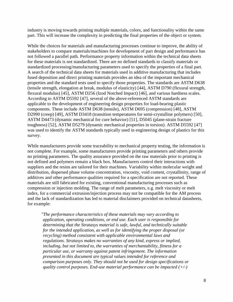
design, durability requirements, and safety factors. The Department of Defense Composite
Materials Handbook has a useful reference that illustrates the staged process of a “building block
approach” for determining the properties of the material and transitioning that information to the
performance of the system [53]. Figure 2 shows the building block approach utilized to minimize
the risk of new material insertion into aerospace structural systems. The building blocks to safely
incorporate new materials into structural design rely on increasing the scale of testing from
coupon tests to more complex component tests and finally full scale tests. This approach will be
used to illustrate where standards for mechanical property measurements of AM manufactured
parts are needed to incorporate new materials or designs into systems.
The parameters that define the system are collected within the design considerations (lower
block, purple in figure). Engineers require estimates of the loading, temperature, moisture
environment of the application, and material information such as mechanical properties, long
term stability, susceptibility to damage, and manufacturing cost prior to designing a part. Design
considerations for AM follow the same requirements as any other manufacturing process.
Supporting technologies (left block, yellow in figure) are the technologies to obtain, measure, and
validate the material information. In AM, this can be difficult because material property
information is often controlled by manufacturers and dependent on AM processing. The engineer
must decide how material properties will be validated through standard test methods, how
statistical analysis will be done to determine the properties of the population, estimate the needs
for post-processing of the part, and determine whether non-destructive techniques are required to
validate internal structural dimensions. If these properties are dependent on material source and
machine manufacturer such as in AM, it becomes difficult to estimate the level of Supporting
Technologies required. The Building Blocks bring all of these considerations together (center
block, green in figure). The building blocks allow engineers to understand material performance,
joining or bonding performance, performance of components working together, and finally full
incorporation into a full scale system test. In AM this may require significant effort for coupon
level tests such as printing a single bead of material to optimize extrusion parameters, moving to
ASTM dog bone geometries to identify optimal print layouts and finally incorporating the AM
part into the other elements and components for further testing. In today’s modeling intensive
10
world, many of these concepts are validated via simulation. Therefore, science-based
standardized testing is required for AM materials to support accurate simulations. This testing
requires confidence in material mechanical properties and performance, which is an area that
AM is lacking.
Figure 2: Building block integration for the development of composite structures [53].
The building block integration approach (Figure 2) may be further expanded to highlight the type
of information gathered from each of the building blocks. Figure 3 shows the building block
approach for a commercial aircraft composite primary structure to provide an estimate of the
level of experimental effort anticipated at each stage of the building block. The use of aggressive
environments (Environment) allows engineers to scale allowed loading or strain limits for the
material based on the effects of temperature, moisture, or cycling. Coupon level testing relies on
simplified sample and test geometries that deliver specific information such as mechanical
properties (modulus, strength, etc.), interlaminar properties, adhesive properties, and durability
(highlighted Coupons and Elements). These tests may easily number in the thousands to build
statistical confidence in performance. Success beyond the coupon level leads to manufacturing
smaller structures with increasing complexity for assembly (inclusion of joints and bolts) and
loading (stress concentrations, off-axis loading). The costs per subcomponent increase, therefore,
sampling is smaller. The coupon level and element level require a firm understanding of the
impact of manufacturing processes on performance, and demand a science-based standardized
testing framework to increase success in the final subcomponent stage. For any processes,
weaknesses must be identified at this time to prevent costly engineering choices in the final
structure and before manufacture and testing of large panels or subcomponents. An additive
part will readily cross between the coupon and element level because performance may be
defined by internal fusion joints, print directions, manufacturer, additive method, and material
supplier. Large panels permit the validation of the design concepts and analysis methods are
11
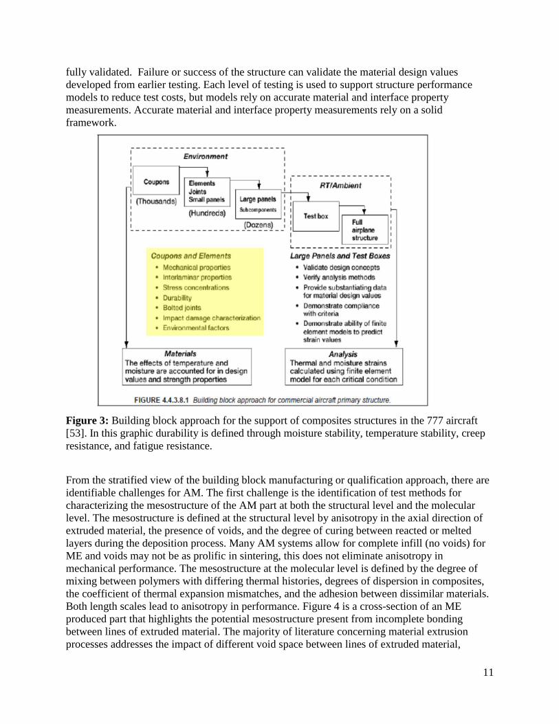
fully validated. Failure or success of the structure can validate the material design values
developed from earlier testing. Each level of testing is used to support structure performance
models to reduce test costs, but models rely on accurate material and interface property
measurements. Accurate material and interface property measurements rely on a solid
framework.
Figure 3: Building block approach for the support of composites structures in the 777 aircraft
[53]. In this graphic durability is defined through moisture stability, temperature stability, creep
resistance, and fatigue resistance.
From the stratified view of the building block manufacturing or qualification approach, there are
identifiable challenges for AM. The first challenge is the identification of test methods for
characterizing the mesostructure of the AM part at both the structural level and the molecular
level. The mesostructure is defined at the structural level by anisotropy in the axial direction of
extruded material, the presence of voids, and the degree of curing between reacted or melted
layers during the deposition process. Many AM systems allow for complete infill (no voids) for
ME and voids may not be as prolific in sintering, this does not eliminate anisotropy in
mechanical performance. The mesostructure at the molecular level is defined by the degree of
mixing between polymers with differing thermal histories, degrees of dispersion in composites,
the coefficient of thermal expansion mismatches, and the adhesion between dissimilar materials.
Both length scales lead to anisotropy in performance. Figure 4 is a cross-section of an ME
produced part that highlights the potential mesostructure present from incomplete bonding
between lines of extruded material. The majority of literature concerning material extrusion
processes addresses the impact of different void space between lines of extruded material,
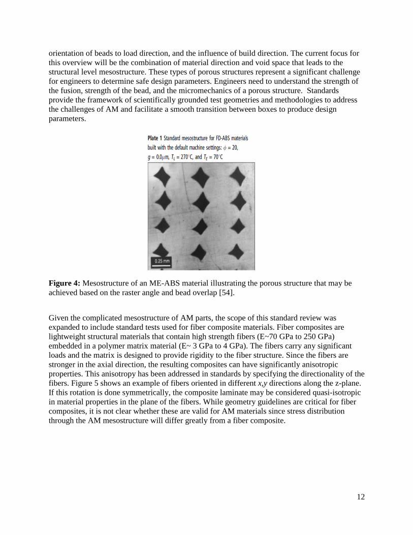
12
orientation of beads to load direction, and the influence of build direction. The current focus for
this overview will be the combination of material direction and void space that leads to the
structural level mesostructure. These types of porous structures represent a significant challenge
for engineers to determine safe design parameters. Engineers need to understand the strength of
the fusion, strength of the bead, and the micromechanics of a porous structure. Standards
provide the framework of scientifically grounded test geometries and methodologies to address
the challenges of AM and facilitate a smooth transition between boxes to produce design
parameters.
Figure 4: Mesostructure of an ME-ABS material illustrating the porous structure that may be
achieved based on the raster angle and bead overlap [54].
Given the complicated mesostructure of AM parts, the scope of this standard review was
expanded to include standard tests used for fiber composite materials. Fiber composites are
lightweight structural materials that contain high strength fibers (E~70 GPa to 250 GPa)
embedded in a polymer matrix material (E~ 3 GPa to 4 GPa). The fibers carry any significant
loads and the matrix is designed to provide rigidity to the fiber structure. Since the fibers are
stronger in the axial direction, the resulting composites can have significantly anisotropic
properties. This anisotropy has been addressed in standards by specifying the directionality of the
fibers. Figure 5 shows an example of fibers oriented in different x,y directions along the z-plane.
If this rotation is done symmetrically, the composite laminate may be considered quasi-isotropic
in material properties in the plane of the fibers. While geometry guidelines are critical for fiber
composites, it is not clear whether these are valid for AM materials since stress distribution
through the AM mesostructure will differ greatly from a fiber composite.

13
Figure 5: Graphic illustrating the directionality of fibers, through z, in a fiber composite
laminate. The orientation and number of fibers controls the performance of the composite.
Mechanical properties: These properties are often defined in terms of the behavior at loads that
do not produce failure or failure behavior itself. For solids, the first case is generally
characterized by moduli that are defined as the stress divided by the strain. Moduli can be
measured with a number of different loading modes: tension, compression, flexure, shear, or
torsion [55], and in the linear region, they are proportionality constants independent of strain.
The moduli of polymeric materials are functions of temperature and time. These dependencies,
particularly temperature, are important. For many polymers used in additive manufacturing,
these properties are often reported in the technical specification sheet in tension (or compression)
and shear loading modes. Since two parameters are needed to model behavior in different
loading directions, an alternative is to report Young’s Modulus and Poisson’s Ratio. Poisson’s
Ratio is the negative ratio of transverse to axial strain.
Failure Properties: As the stress increases, materials begin to fail via plastic deformation (non-
linear stress vs. strain) or brittle fracture. One approach to quantify failure behavior is by
determining yield strength, ultimate strength, and impact strength. Each one of these may be
defined in relationship to the mode of loading: tension, compression, flexure, shear, or torsion
[55]. For many polymers used in additive manufacturing, these properties are often reported in
the technical specification sheet in tension or compression loading modes. On the other hand,
these parameters do not adequately characterize materials that fail by the propagation of cracks.
To describe this behavior requires fracture parameters that are often not reported in the technical
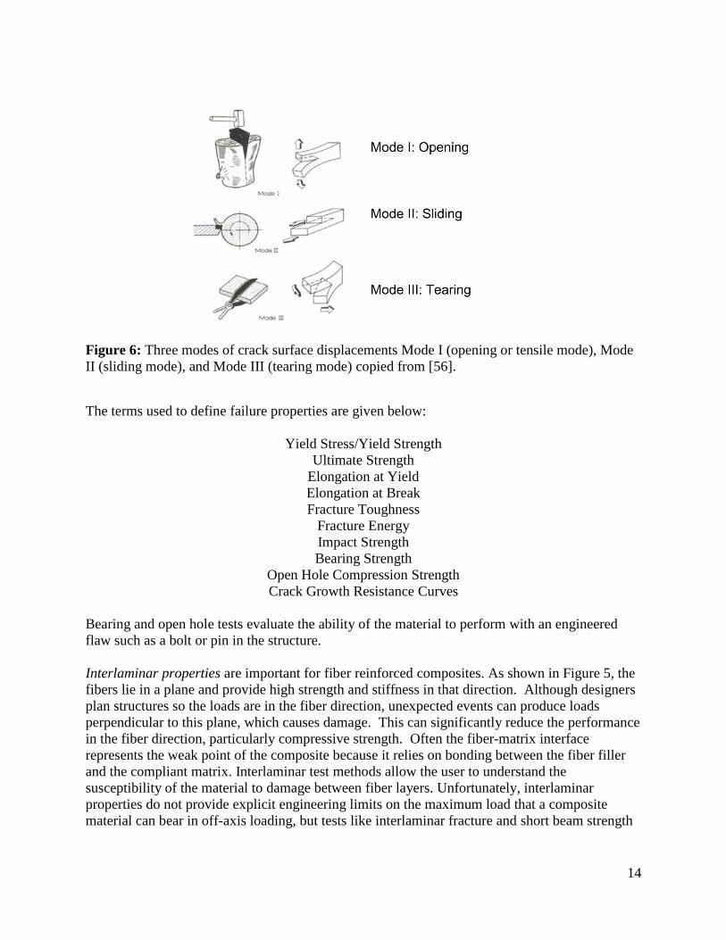
sheet [53]. The fracture toughness or fracture energy of the material is [55] defined in three
modes (I: crack opening, II: in-plane shear, and III: out of plane shear) as shown in Figure 6.
Standards are available to test in Mode I, Mode II, and mixtures of Mode I and II, although the
complex shapes of many AM parts may increase the importance of Mode III. Fracture toughness
is a critical factor for ME and LS created polymer parts and given the complex mesostructure
and anisotropy, it may be difficult to induce purely one loading Mode for testing.
14
Figure 6: Three modes of crack surface displacements Mode I (opening or tensile mode), Mode
II (sliding mode), and Mode III (tearing mode) copied from [56].
The terms used to define failure properties are given below:
Yield Stress/Yield Strength
Ultimate Strength
Elongation at Yield
Elongation at Break
Fracture Toughness
Fracture Energy
Impact Strength
Bearing Strength
Open Hole Compression Strength
Crack Growth Resistance Curves
Bearing and open hole tests evaluate the ability of the material to perform with an engineered
flaw such as a bolt or pin in the structure.
Interlaminar properties are important for fiber reinforced composites. As shown in Figure 5, the
fibers lie in a plane and provide high strength and stiffness in that direction. Although designers
plan structures so the loads are in the fiber direction, unexpected events can produce loads
perpendicular to this plane, which causes damage. This can significantly reduce the performance
in the fiber direction, particularly compressive strength. Often the fiber-matrix interface
represents the weak point of the composite because it relies on bonding between the fiber filler
and the compliant matrix. Interlaminar test methods allow the user to understand the
susceptibility of the material to damage between fiber layers. Unfortunately, interlaminar
properties do not provide explicit engineering limits on the maximum load that a composite
material can bear in off-axis loading, but tests like interlaminar fracture and short beam strength
15
can indicate general ranking. For composites, standard test methods for interlaminar properties
are:
Short beam strength
Shear modulus
Ultimate shear stress strength
Durability: Durable material properties may be quantified using several standards depending on
the usage of the material. In the context of this review, durability is addressed for mechanical
durability, specifically creep and fatigue. There are standards available in ASTM and ISO that
define exposure conditions for moisture, temperature, and artificial sunlight exposure on
materials. Creep is important for understanding the ability of the material to withstand long-term
static loading. Fatigue properties are important for understanding the ability of the material to
withstand cycling loading during usage. Finally, impact strength is a measure of the material to
withstand high strain rate loading and evaluate the ability of the material to absorb energy and
resist damage. Mechanical properties that define mechanical durability are:
Creep Modulus
Creep Rupture
Fatigue life (S-N plots/R-N plots)
Standards are important for mechanical and failure properties because they are the language that
mitigates risk within the design and allows engineers to build structural and safety critical parts
with a known performance window. The specific ASTM and ISO standards that are applicable to
quantify the material properties listed above will be addressed individually.
6. Challenges for Mechanical Property Characterization:
While AM provides the opportunity to quickly go from design to product especially for parts that
have difficult or impossible to machine features, challenges remain for predicting mechanical
performance. Many AM processes differ from traditional polymer processing in that not all of
the material is melted and homogenized. The AM process of depositing layers of polymeric
material results in parts with anisotropic properties, residual stress, and this is a significant
challenge. Researchers and Original Equipment Manufacturers (OEMs) must establish the
standardized methods to determine material properties from AM processing rather than the
mechanical properties of a particular design. Peer-reviewed literature has begun to highlight
complexity in relating material properties, AM mesostructure, and part design for standardized
testing. Despite the importance of this problem for the success of AM as a critical manufacturing
process, the literature available in this area is not significantly large. Figure 7 shows the typical
geometrical variables related to ME deposition geometry.
16
Figure 7: Graphical representation of process variables related to the build geometry for additive
manufacturing. a) raster angle, b) extruded filament height and layer width, c) air gap between
extruded filaments, d) combinations of variables (T, air gap, width, height, velocity) can increase
the coalescence between filaments, e) the build direction can affect the load transfer between
filaments and interfaces.
The majority of studies have focused on the impact of raster angle, air gap, filament width, layer
height, and build orientation to major part axis (i.e. x, y, or z-direction). Build orientation allows
one to capture interacting factors such as filament length, temperature gradients, and nozzle
velocity on mechanical properties. Many additive systems that rely on material extrusion
processes allow for full infill of the deposited part, but it was not possible to compare literature
studies directly. Evidence for mechanical anisotropy was more readily identified in the literature
for powder bed fusion processes.
The impact of processing for anisotropic mechanical properties in material extrusion
has been identified by multiple authors with ME processing of ABS polymers as a major focus
[54, 57-68]. In the case of ME, AM parts exhibit inferior mechanical properties compared to the
as-received polymer filament that feeds the AM extruder head and compression molding or
injection molded parts constructed from this same as-received filament. Raster angle is a process
parameter that influences anisotropy and strength in AM parts. Rodriquez showed reductions in
modulus can range from 11 % to 37 % [65]. In general, parts were stronger when the beads were
aligned in the loading direction for tensile loading [57, 64], mixed angles for flexure [57, 58],
and orthogonal to loading for compression [67]. Ahn used twelve layers of ABS oriented in
[0 º], [45 º /- 45 º ], [0º /90 º ] and [90 º ] to investigate the effect of raster angle [57]. Alignment
of long fibers with the loading path increased strength, but gaps between bead layers reduced
strength. Similar work in unidirectional deposition of materials supports this idea. Es-Said found
that increasing raster angle lowered strength, but had little effect on modulus [59]. They also
17
found that failure tended to occur in the deposition lines. As the raster angle increases the tensile
properties of the material are reduced [57, 65]. Huang has shown that tensile and shear properties
of unidirectional ABS parts reach a minimum around raster angles of 50º [61]. Similar results
have been found for ME production of PC materials. Masood could achieve approximately 80%
of an injected molded material by aligning the beads with loading [63]. Hill conducted a
systematic study of raster angle on unidirectional parts with similar density and found that
aligning the beads in the axial direction produced the best failure properties [60]. The strength
could be modeled using micromechanics to account for the fusion strength.
The air gap influences void percentage, which plays a large role in determining mechanical
properties. The strength of the AM part is not only derived from lines of extruded filament, but
the interaction between filaments is important. The presence of voids and sharp corners increase
stress within the part and failure can initiate at these features [58]. In general, minimizing the gap
between filaments increases the contact area between filaments and leads to a stronger fusion
interface. Rodriguez has shown that a combination of process parameters may be used to control
the void space, and he could model the resulting structure using laminate theory [65]. ME relies
on the thermal gradients between neighboring filaments to allow the thermoplastic polymers to
diffuse and form a stronger fusion interface. These fusions have been compared to the matrix in a
fiber reinforced composites because they hold the filaments together [65]. The time required to
maximize bond strength between successive filaments is not immediately known from technical
data sheets, but it is related to the structure of the polymer (molecular weight, glass transition
temperature, crystallinity, etc.) and the thermal gradient between the new filament and the
previous filaments. A guideline was developed to minimize the air gap and optimize the bead
width or height to increase contact area in order to improve bond strength. Sun observed
temperature profiles in ME and bead interface formation to quantify interface formation. He
found that envelope temperature and convection in the build chamber have a significant effect on
mesostructure [69]. Sood et al. used a response surface developed from design of experiments
coupled to neural network analysis to demonstrate the non-linear behavior of printing parameters
and utilized neural network modelling to predict compressive properties [67, 70]. Another
empirical study led to six build rules to help designers maximize mechanical performance [57].
These studies have highlighted the complicated relationship between the build parameters, part
design, and final properties.
There are examples of unintended consequences from not accounting for interacting parameters.
Decreasing the bead width reduces residual stress in the filament and can increase diffusion
length, but requires more laps to create the part. Residual stress is caused by the contraction of
the polymer filament on cooling. In the case of semi-crystalline materials, the contraction of
volume from crystallization increases residual stress at interfaces. In order to fill the space with a
smaller filament width, the nozzle must complete a higher number of long passes and short
passes for direction reversal. The extruding nozzle will change speed to accommodate the
printing process; the corollary for sintering is laser raster speed and energy. The successive
thermal cycling caused by changes in nozzle speed impacts thermal diffusion because speed
changes impact residence time [70]. Another example is maximizing the temperature and
filament height can lead to part distortion and surface roughness that negatively impacts
appearance and mechanical properties. Orientation of the polymer during extrusion will reduce
strain to failure up to 33 % [58] and increase the time for polymer diffusion, but orientation has
18
not been sufficiently addressed in the literature. Failure in these materials is often brittle and
driven by build construction. Larger filament widths, oriented polymer within beads, and poor
diffusion are all suspected to lead to inter-laminar failures facilitated by defects and surface
roughness at the fusion lines. These factors need to be accounted for in models, validated
through standardized testing, and incorporated into the process workflow to support AM.
It is difficult to isolate the impact of build direction on anisotropy because this is often
confounded with other build parameters. Riddick et al. combined xz, yz, and xy build directions
with changes in bead length and raster angle combinations of [0 º], [0º /90 º] and [90 º ] and
found that the xz direction had the highest modulus (2.67 GPa) and strength (15.26 MPa) due to
a combination of void filling and optimal raster geometry [64]. Others have found that build
paths that maximize alignment of fibers in the loading direction increased strength [58]. There
are a small number of studies investigating the durability of ME parts. One study showed that a
PEI/PC blend aged at room temperature and water was stable over 52 weeks and relatively
insensitive to short time exposure to aerospace solvents [71].
Similar challenges exist for powder bed fusion processing and concern the impact of thermal
gradients and void space in the part. If the layer heights are too large, the powder acts as a
thermal insulator which prevents heat transfer to the lower powder layer. This can reduce the
consolidation of molten material into the gaps below and inter-diffusion of polymer species [7].
The crystallization temperature of the material is important for the increase of bonding between
the molten beads [72]. Shrinkage has been shown to depend on different build parameters based
on laser raster direction, where laser power and scan length are critical for x-direction while
hatch spacing and part bed temperature are critical for the z-direction [73]. Recycled powder
presents a challenge for laser sintering. There is potential for polymer aging and crosslinking for
a material that has been previously processed, but not sintered. This aging increases melt
viscosity and prevents flow, which creates weak interfaces and defects within the part. Thermal
control of the powder bed is also important. Improper powder bed temperature leads to
interruption of the thermal gradients during the sintering process which can lead to reduction in
performance [72]. Leigh found that increasing the size of the polymer interface, characterized
by an h/r ratio (see Figure 6b and 6d) increased the yield stress and ultimate tensile strength [7],
but there was limited information found on durability studies for LS parts. One study showed
that these materials exhibited a slight drop in mechanical properties when subjected to aggressive
automotive fluids, similar to the performance of the base polymers [74].
In the case of material jetting, the kinetics of the photo-polymerization reaction and thermal
annealing of the part must lead to uniform cross-linking between successive layers. Lee found
that 3D printing produces anisotropic materials with much lower compressive strength [62].
Additional challenges include the presence of additives, printing on an over-cured surface, and
the proprietary knowledge of formulations. Similar to thermoplastic technologies, the print resin
formulations are not known to users. Therefore, the impact of reactants, catalysts, and monomer
molecular weight are difficult to separate. The photochemistry literature of dental resins,
photolithographic patterning, and radiation curing is expected to contain a wealth of prior art
concerning optimization of formulations and processing. A nanocomposite deposition system
that produced composite parts, but requires a machining step after successive layers had
mechanical performance closer to ME produced parts, although the materials remained
19
anisotropic. Ang et al investigated the impact of trapped volume (voids) and trapped material for
various rapid prototyping metrologies [10]. They found that these artifacts affect the
functionality and dimensional stability of the final part, but they did not measure the mechanical
properties.
Research is moving towards a better understanding of raw material microstructure, the physics
and chemistry of polymer fusion and photopolymerization, and utilizing composite modeling to
understand anisotropic properties as a function of the AM mesostructure. Fusion and coalescence
have been presented in terms of a Frenkel-Eshelby formulation [61]. Huang was able to combine
a force model with an understanding of the magnitude of coalescence to predict the performance
of ABS. Composite models have been used to understand the deformation of these materials with
an eye toward design variables and identifying fusion contributions to properties [58, 60, 65].
Many of these studies have been done on industrial or consumer-grade equipment [68], and it is
not clear how the structure of the raw materials and tolerances of the process variables were
controlled. There is much work that is required to drive current research towards industrially
relevant AM standards.
7. Overview of Standard Testing Methods
There are two standards groups addressing AM. In ASTM committee F42 has jurisdiction over
Additive Manufacturing Technologies and subcommittee F42.05 addresses materials and
processes specifically [75]. TC 261 promulgates standards in the AM fields for the ISO. Both of
the groups currently address mechanical testing of AM materials and parts via reference to
established standards [76]. The following analysis describes the applicability of existing
standards to mechanical testing of polymer AM materials and parts.
7.1. Tension
These standards are classified for plastics (ASTM D638 [44], ISO 527-2 [77]) and composites
(ASTM D3039 [78], ISO 527-4 [79, 80]). The standards utilize dog-bone or end tab specimens
whose geometry is based on the thickness of the sample or the type of composite. Tension
measurements provide Young’s modulus, Poisson’s ratio, Yield Stress, Strength, and Elongation
to Break. The standards for composites address the orientation of fibers within a composite, but
the applicability of such standards to AM materials has not been thoroughly described in the
literature. Ahn found that the ASTM D638 type I sample geometry caused premature failure of
specimens. Early failure was caused by a stress concentration within the radius of the dog bone
near the gauge length. This area of specimens contained the ends of filaments, which caused
excessive shear. The authors switched to the ASTM D3039 geometry to alleviate the problem.
However, this was the only reference found with this problem. ISO 458 [81], which was not
reviewed, provides the test standard for the stiffness of a material under torsion.
7.2. Flexure
ASTM D790 [45] and ISO 178 [82] are equivalent standards that utilize a three-point bend
method to measure the flexural modulus, flexural strength, flexural stress and strain at break
within a 5 % strain limit. If the strain limit is not met, then ASTM D6272 [83], which is a four-
20
point method, is used to increase the chance of achieving a failure measurement. This test
reduces the stress concentration associated with the center roller in a three point test. These
standards are applicable for unreinforced and reinforced materials. For composites containing
high modulus fibers, ASTM D7264 [84] should be used for testing. The standard does not
address the specific challenges for AM materials that may have anisotropic properties.
7.3. Compression
The applicable standards for compression measurements are ASTM D695 [48] and ISO 604 [85].
ASTM D3410 [86] and ISO 14126 [87] are specific to compression of a fiber reinforced
composite in-plane direction. The standards provide measurement of compressive modulus,
compressive yield stress, compressive strength at failure, and compressive strain at failure. There
are geometrical restrictions for the diameter and height of the sample.
7.4. Shear
There are a number of different standard tests to measure the shear modulus and strength of
materials. The fiber reinforced composite standards (ISO 14129 [88], ISO 14130 [89],
ASTM D2344 [90], and ASTM D3518 [91]) are not directly applicable to AM. These methods
are developed for polymers reinforced with high strength fibers or textiles in specific orientations
to the loading direction. The standards require determination of specific interlaminar failure
modes between the aligned fibers. These types of samples are not typically manufactured in AM.
There are also two notched specimen standards ASTM D7078 [92] and ASTM D3846 [93] for
measuring shear properties. These standards utilize specimens with specific notch geometries
and defined alignment of the fiber reinforcement. These test methods may not be directly
applicable to AM manufactured materials for two reasons. First, AM produced parts do not
possess the large ratio of moduli and failure strength in different directions that is found in fiber
composites, therefore the mechanics of load distribution and crack propagation will be different
in an AM material. Second, composite laminates may be manufactured with sharp initiation
cracks in the matrix between the fiber layers. These cracks increase the precision of the test used
to measure a material failure property. The current thermal processing methods in AM are not
conducive to intentionally producing a well-defined, sharp initiation crack, and this will hinder
the ability to characterize failure behavior. There are methods to introduce a sharp crack into a
material. Fatigue, which is used for metals, does not work for polymeric materials, and the use
of a sharp edge, such as razor blades, may not produce a proper crack in AM parts.
There are only two shear standards that are directly applicable to AM. These are ASTM D4255
[94] and ISO 15310 [95] to determine the shear modulus of plastics and fiber reinforced
materials, respectively. These standards allow for testing isotropic materials, but there is no
guidance for testing materials constructed via AM.
7.5. Creep
Creep measurement standards provide the methodology to measure dimensional changes in
samples under load as a function of different exposure environments such as temperature,
aqueous, or surfactant solutions. There are a variety of loading environments: tensile,
compression, flexure, and solutions. ASTM D2990-09 [49] references ASTM D543 Practices for
21
evaluating the resistance of plastics to chemical reagents for testing in environmental conditions
[96] that specifies solution composition for sample immersion. The ISO standard equivalent is
ISO 899 [97, 98]. There are restrictions on the ratio of the length to the cross-section. The
method recommends testing at a minimum of two different test temperatures within the use range
of the material to understand the effect of temperature. Loading at seven stress levels to produce
creep-rupture at different times up to 3000 h provides a measure of long term performance.
Design data for creep is obtained by testing materials at different stress levels to produce 1 %
strain in 1000 h. There is no guidance provided for anisotropic samples, such as fiber
composites.
7.6. Fatigue
ASTM D7774 [99] is the standard for uniaxial loading with no equivalent in ISO. The test
frequency can range between (1-25) Hz, but less than 5 Hz is recommended. This frequency
reduce the chances of heat generation in the sample. The test method allows generation of a
stress or strain as a function of cycles, with the fatigue limit characterized by failure of the
specimen or reaching 107 cycles. The 107 cycle value is chosen to limit the test time, but
depending on the applications this may or may not be the best choice. The maximum and
minimum stress or strain levels are defined through an R ratio. The R ratio is the ratio of
minimum to maximum stress or displacement that the material is cycled through during testing.
Testing is conducted within the elastic limit of the material. For this standard, samples may be
loaded in either tension or compression.
ASTM D7791 [100] and ISO 13003 [101] are the test methods for flexure fatigue of plastics.
The subject matter of the tests is similar, but technically different. In both tests, the loading is
sinusoidal. ASTM D7791 utilizes either a three-point or four-point loading with cycling
occurring in positive and negative directions. Control occurs in either stress or strain versus cycle
number. The R ratio is -1 and the stress or strains do not exceed the proportional limit. The test
ends at either failure or reaching 107 cycles.
ISO 13003 calculates the ultimate tensile/flexural strength for fatigue loading rate. In strain
control, the end of the test is listed as the damage level related to specimen stiffness reduction of
20 %. Four fatigue levels are tested in accordance with the fatigue life of interest or the range of
stress/strain of interest. Similarly, strain or stress vs. the number of cycles is reported. Neither
standard addressed the challenges associated with AM processing inducing anisotropy within the
materials.
There are two standards that relate to fatigue delamination or crack propagation. These are
ISO 15850 [102] and ASTM D6115 [103]. Both of these standards are specifically applicable to
the measurement of fracture energy in the interlaminar region of a fiber composite. Similar to
other composite specific standards, it is not clear whether AM materials would meet the fracture
mechanics assumptions that support these standards.
7.7. Fracture Toughness
Fracture toughness measurements are used to determine the energy required to initiate crack
propagation from a precrack within a material or composite. These values are used for designing
22
parts and developing materials. These standards often require the development of a sharp pre-
crack within a material, application of load, and monitoring of the load, displacement, and crack
progression. A linear elastic fracture mechanics analysis was used to develop measurements of
fracture energy (GiC) and fracture toughness (KiC), where i indicates the mode of loading I, II, or
III, see Figure 6. In composites, these measurements are used to determine the fracture toughness
between plies containing high modulus fibers or textiles. In polymers, this test provides material
properties for engineering design. These often require the insertion of a pre-crack material to
create the sharp crack, which may be problematic given the dimensional limitations for AM
processes.
ISO 15024 [104] and ASTM D5528 [105] are specifically for fiber reinforced composites. These
standards are used to generate crack growth resistance curves (R-curves), which are measures of
delamination resistance through the composite. They are not directly applicable to current AM
manufacturing because continuous fibers are not present. It is not immediately clear whether
these concepts could work for evaluation of the mesostructure or fusion zone in an AM material.
ISO 29221 [106] is a standard for the plane-strain crack-arrest toughness in a compact tension
specimen. This requires a sharp initial crack and a groove in the sample to limit the location of
crack growth across the specimen. The challenges in AM relate to the dimensional resolution of
the AM process and whether the impact of build direction on the propagation of the crack.
ISO 13586 [107] applies to the measurement of rigid and semi-rigid thermoplastics and
discontinuous fiber composites. The biggest question is the influence of the mesostructure
created during the AM process to measure a material property. An amendment to ISO
13586 [108] provides testing injected molded composites with directions for testing longitudinal
and transverse processing directions. This would be an acceptable place to start for determining
the applicability of this test standard to AM parts.
ASTM D6068 [109] is for the development of J-R curves for plastic materials. This is a specific
method to develop an understanding of parameters for cohesive zone modeling of crack
propagation. The method requires optical measurement of crack growth. This method may be
applicable to specific types of deposition processes such as powder bed fusion of clear
thermoplastics or material jetting of clear photopolymers, but it would still require the machining
of a crack into the sample.
7.8. Impact
ISO 179 [110, 111] and ASTM D6110 [112] describe the method for the Charpy impact test. ISO
180 [113] and ASTM D256 [46] are the methods for Izod impact testing. Impact testing is
mentioned with technical data sheets for many AM relevant polymers. It is not clear how the AM
material is prepared and oriented for impact testing from the material data sheets. The main
differences between the tests are the material position and notch placement. The load is applied
rapidly by hitting the sample with a heavy striker. In the Izod test, the material is in a vertical
position and the notch faces the striker. In the Charpy test, the material is horizontal with the
notch away from the striker. The Charpy notch may be a V or a U-shaped notch. Similar to
fracture toughness testing, it is not clear whether the notch may be sufficiently deposited into the
AM part or should be machined at a later date.
23
7.9. Bearing Strength and Open Hole Compression
These tests represent functional strength tests for composites that will be fastened using bolts. It
can also provide some insight into the effects of a damage region on performance. The specific
standards are ASTM D953-10 [114], ASTM D5961 [115], and ASTM D6484 [116]. In ISO, the
specific standards are ISO 12815 [117] and ISO 12817 [118]. The tests develop design
parameters for integrating composites materials together and within structures. Currently, no
demand was observed in the literature for these types of measurement standards by the AM
community, which is not to say the demand does not exist. It is feasible that as AM materials are
integrated with other structures such as in the human body, the community will need to
understand the impact of part design on load carrying capability and whether the part will deform
over time. Current standards should be directly applicable, but there should be comments
provided on material isotropy.
8. Standards Applicability Assessment
In the following charts, ASTM and ISO standards were evaluated to determine their applicability
to additive manufacturing. One of three classifications is given for each standard. If special
consideration should be noted for the standard, specific notes are provided. The list covers
standards for plastic materials and composites. The following labels are used for assessing
applicability of the standard:
• YES – The standard should be applicable for additive manufacturing with very minimal
or no modifications.
• YES WITH GUIDANCE – The standard should be generally applicable for additive
manufacturing, but there may be limits on its applicability, and some modifications or
additional considerations are probably needed. These include:
o Geometrical limits on test specimens
o Required post-processing such that specimens built via additive manufacturing
meet the requirements of the standard; this typically includes surface finish,
dimensional requirements, or pre-crack requirements.
o Material isotropy requirements. AM specimens often have inherent anisotropy.
The measurement methods that specify applicability for isotropic materials may
still work, but the measured results may have larger uncertainties. This includes
consideration of separating material properties from part properties.
o Application specific considerations, such as elevated testing temperatures or
immersion environments.
• NO – The standard requires specimens that cannot be built via AM, even major
modifications may not be adequate, another method is better suited for the measurement
or the measurement simply is not applicable.
In some cases standards were identified and listed in the applicability index, but they were not
specifically reviewed.

24
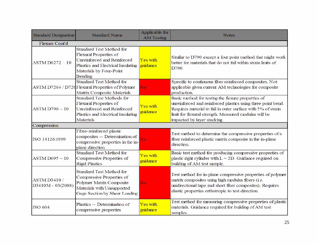
25
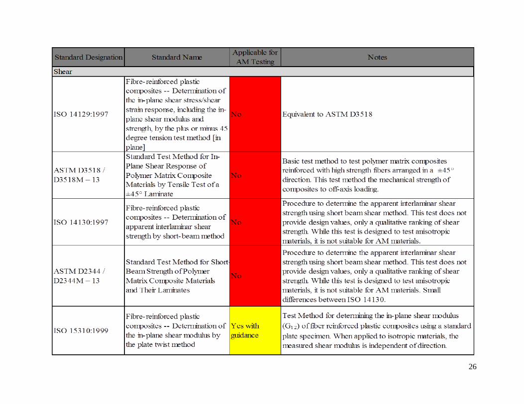
26
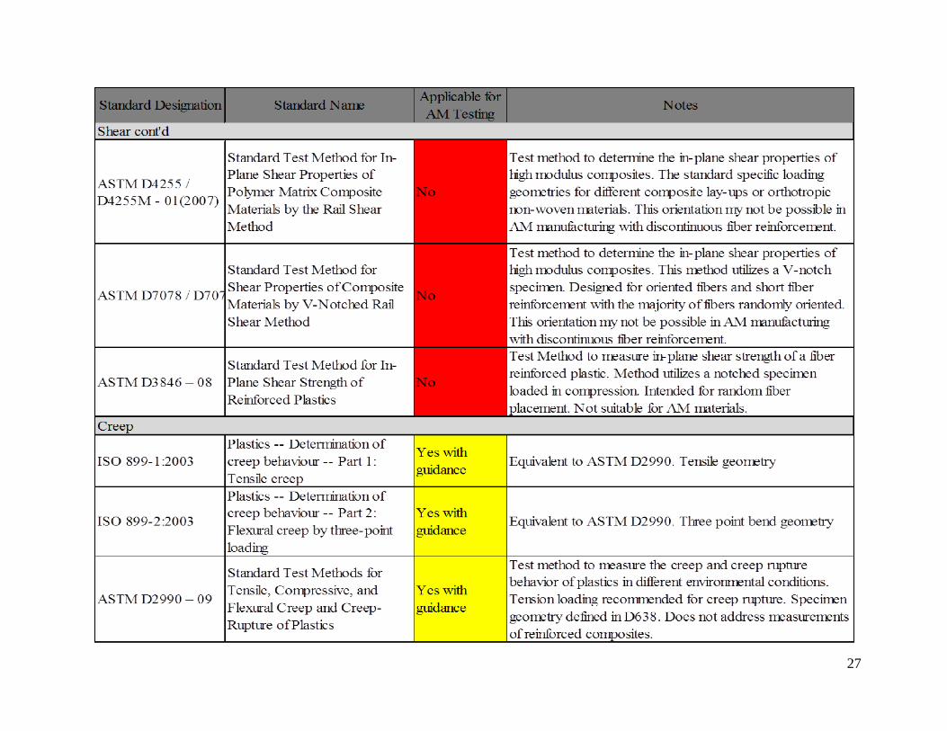
27
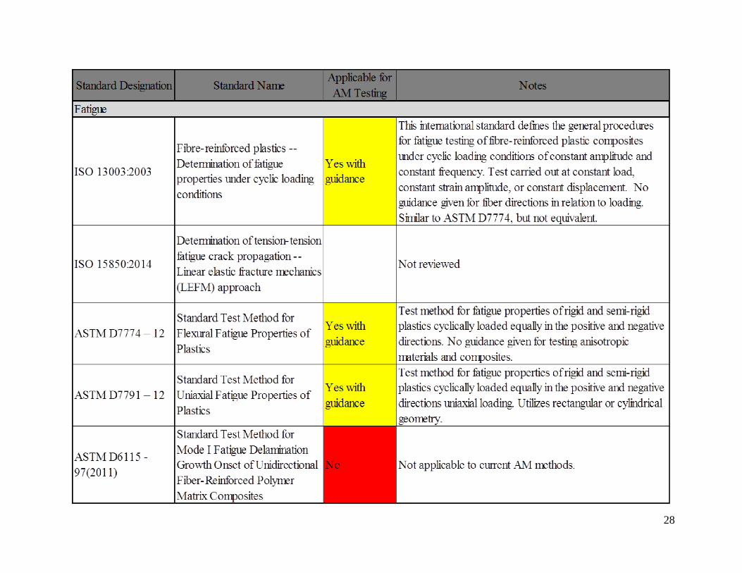
28
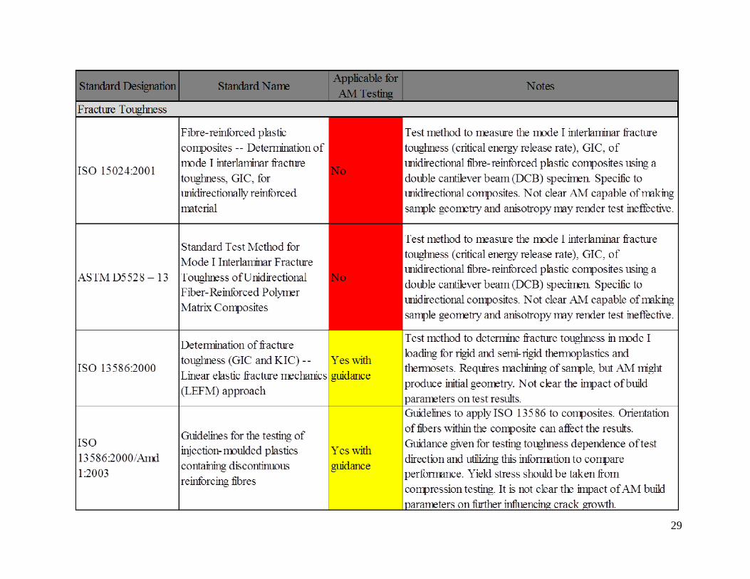
29
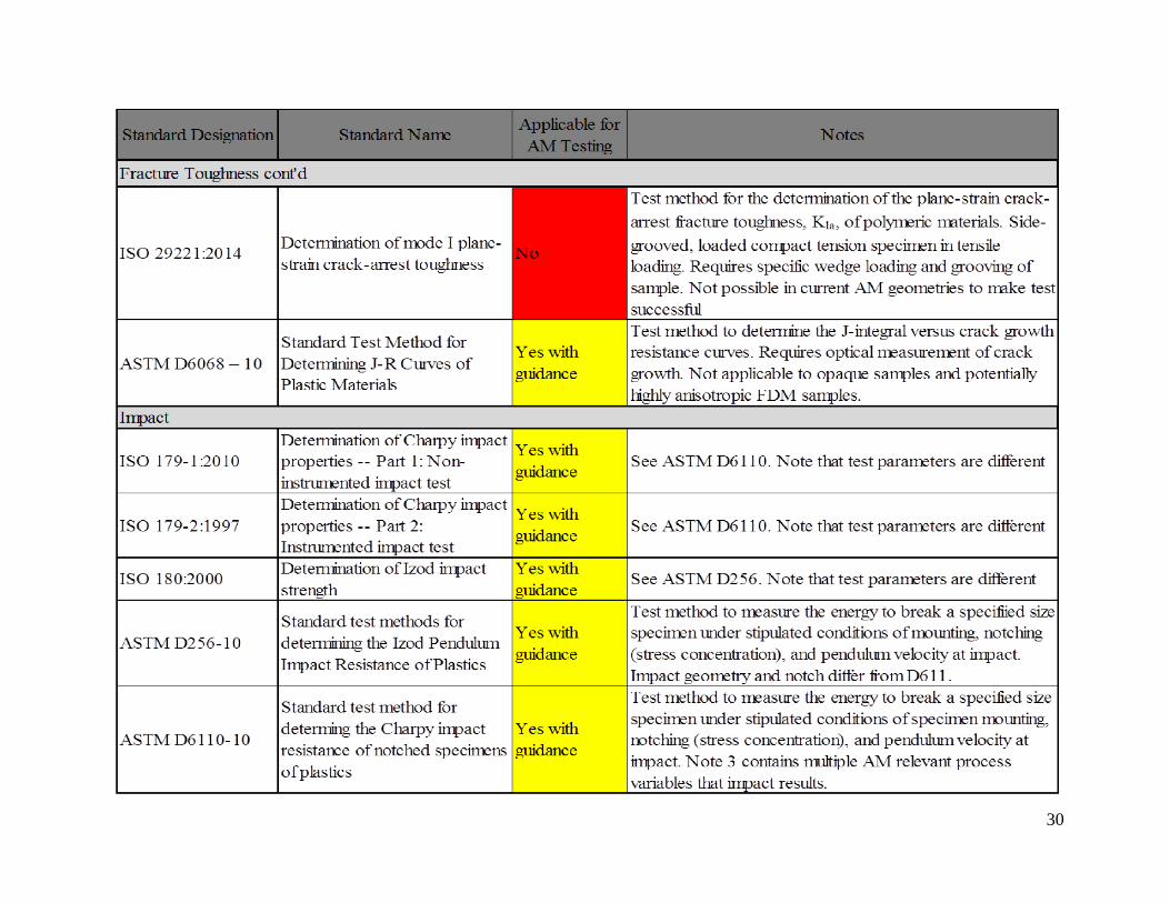
30

31
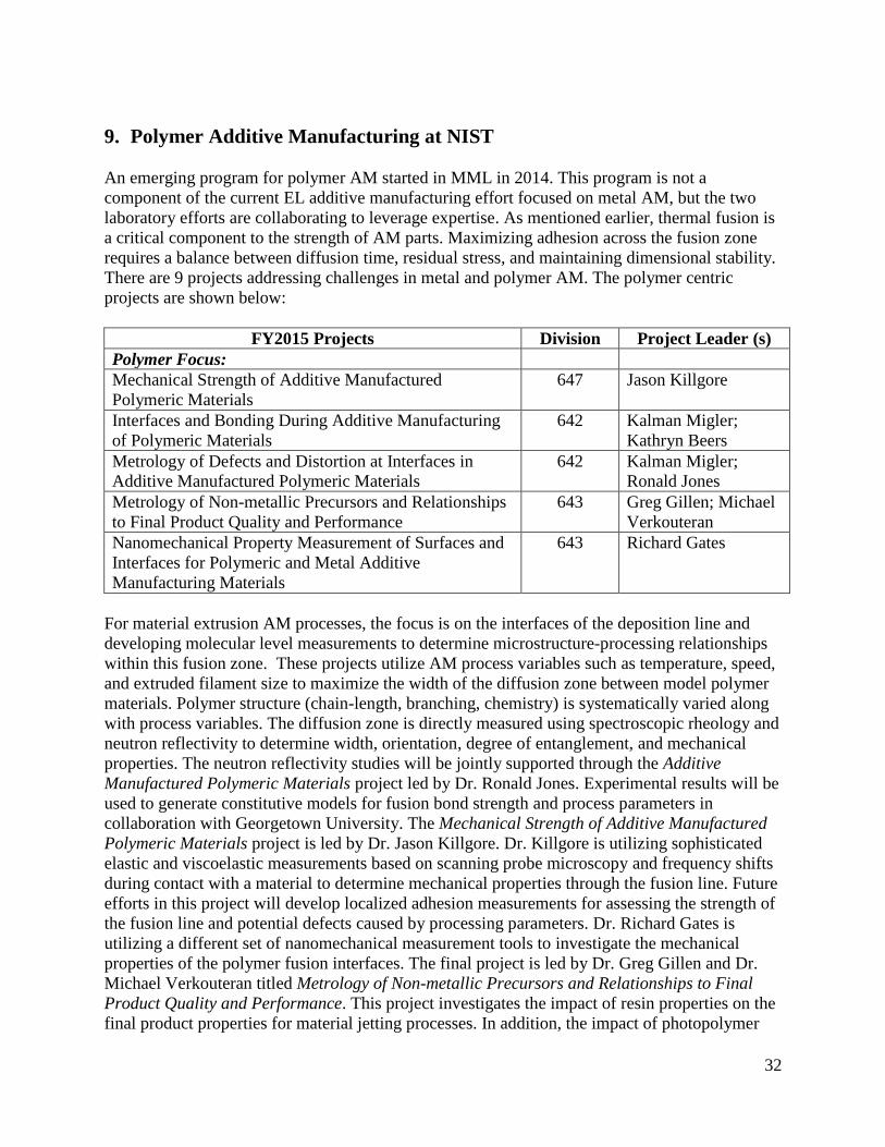
32
9. Polymer Additive Manufacturing at NIST
An emerging program for polymer AM started in MML in 2014. This program is not a
component of the current EL additive manufacturing effort focused on metal AM, but the two
laboratory efforts are collaborating to leverage expertise. As mentioned earlier, thermal fusion is
a critical component to the strength of AM parts. Maximizing adhesion across the fusion zone
requires a balance between diffusion time, residual stress, and maintaining dimensional stability.
There are 9 projects addressing challenges in metal and polymer AM. The polymer centric
projects are shown below:
FY2015 Projects Division Project Leader (s)
Polymer Focus:
Mechanical Strength of Additive Manufactured
Polymeric Materials
647 Jason Killgore
Interfaces and Bonding During Additive Manufacturing
of Polymeric Materials
642 Kalman Migler;
Kathryn Beers
Metrology of Defects and Distortion at Interfaces in
Additive Manufactured Polymeric Materials
642 Kalman Migler;
Ronald Jones
Metrology of Non-metallic Precursors and Relationships
to Final Product Quality and Performance
643 Greg Gillen; Michael
Verkouteran
Nanomechanical Property Measurement of Surfaces and
Interfaces for Polymeric and Metal Additive
Manufacturing Materials
643 Richard Gates
For material extrusion AM processes, the focus is on the interfaces of the deposition line and
developing molecular level measurements to determine microstructure-processing relationships
within this fusion zone. These projects utilize AM process variables such as temperature, speed,
and extruded filament size to maximize the width of the diffusion zone between model polymer
materials. Polymer structure (chain-length, branching, chemistry) is systematically varied along
with process variables. The diffusion zone is directly measured using spectroscopic rheology and
neutron reflectivity to determine width, orientation, degree of entanglement, and mechanical
properties. The neutron reflectivity studies will be jointly supported through the Additive
Manufactured Polymeric Materials project led by Dr. Ronald Jones. Experimental results will be
used to generate constitutive models for fusion bond strength and process parameters in
collaboration with Georgetown University. The Mechanical Strength of Additive Manufactured
Polymeric Materials project is led by Dr. Jason Killgore. Dr. Killgore is utilizing sophisticated
elastic and viscoelastic measurements based on scanning probe microscopy and frequency shifts
during contact with a material to determine mechanical properties through the fusion line. Future
efforts in this project will develop localized adhesion measurements for assessing the strength of
the fusion line and potential defects caused by processing parameters. Dr. Richard Gates is
utilizing a different set of nanomechanical measurement tools to investigate the mechanical
properties of the polymer fusion interfaces. The final project is led by Dr. Greg Gillen and Dr.
Michael Verkouteran titled Metrology of Non-metallic Precursors and Relationships to Final
Product Quality and Performance. This project investigates the impact of resin properties on the
final product properties for material jetting processes. In addition, the impact of photopolymer

33
precursor structure and formulation on final properties will be investigated. These efforts are
important for developing the measurement science to predict fusion interface strength as a
function of processing parameters. The MML effort has a strong focus on structure-property
relationships for molecular level performance. This is an important step, but this work would be
greatly enhanced with additional work to transition molecular-level knowledge to testing and
qualification of AM parts.
There are several areas where NIST laboratories may leverage core expertise to accelerate the
measurement science delivered to the AM community. The mechanical properties of any AM
part will be a function of the composite and includes the material properties, build geometry
(raster angle, filament size, gap, temperature, etc.), voids and defects, and roughness. There are
many ASTM and ISO test standards available for AM materials, but a technical basis is required
to provide the guidance for testing additive parts to account for anisotropy and develop the
models required to predict final mechanical properties. This technical basis will transition the
molecular structure-property measurements from MML into standards for testing coupon level
samples in the purview of ASTM and ISO standards. Standardizing how materials are built and
tested in order to determine mechanical and failure performance for parts in tension,
compression, flexure, fatigue, and fracture is key to deploying engineered AM structures with
confidence. Further, the development of composite mechanics models for properties of AM parts
will inform the MML effort on molecular scale measurements. This engineering effort would
close the measurement loop across multiple length scales and provide a route to translate the
innovations from molecular scale measurements into the advancement of AM part quality and
strength. This is an area where EL and MML may leverage their respective AM programs to
improve measurements science, standards, and the AM community. Similar examples of
successful collaboration exist in the metal AM programs. A second area of collaboration would
be the development of standard reference materials for printing to calibrate the performance of
different AM machines. Ultimately, the constitutive equations, standards, and design decisions
developed for polymer AM need to be brought into the AM workflow. This is a third area of
collaboration between the EL and MML Additive Manufacturing efforts.
10. Conclusion and Path Forward
Polymer AM is gaining attention from many press-worthy applications that has helped drive
advances in materials and manufacturing equipment. There has been significant investment from
private industry and government to foster AM growth. Polymer AM equipment is becoming
more accessible to the general public further increasing the possibility for distributed
manufacturing of high quality parts and increasing innovation in design. Advances in machine
design have led to AM with high performance semi-crystalline polymers and composites, which
are creating a demand for better mechanical property measurements. AM process parameters
exhibit a non-linear effect on mechanical properties and one of the challenging aspects is
maximizing the fusion bond and relating process parameters to polymer structure for
thermoplastics, semi-crystalline materials, composites, and thermosets.
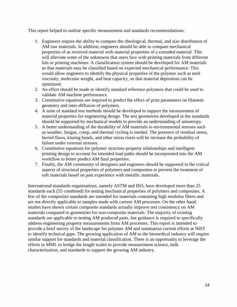
34
This report helped to outline specific measurement and standards recommendations:
1. Engineers require the ability to compare the rheological, thermal, and size distribution of
AM raw materials. In addition, engineers should be able to compare mechanical
properties of as received material with material properties of a extruded material. This
will alleviate some of the unknowns that users face with printing materials from different
lots or printing machines. A classification system should be developed for AM materials
so that materials may be classified based on expected mechanical performance. This
would allow engineers to identify the physical properties of the polymer such as melt
viscosity, molecular weight, and heat capacity, so that material deposition can be
optimized.
2. An effort should be made to identify standard reference polymers that could be used to
validate AM machine performance.
3. Constitutive equations are required to predict the effect of print parameters on filament
geometry and inter-diffusion of polymers.
4. A suite of standard test methods should be developed to support the measurement of
material properties for engineering design. The test geometries developed in the standards
should be supported by mechanical models to provide an understanding of anisotropy.
5. A better understanding of the durability of AM materials to environmental stresses such
as weather, fatigue, creep, and thermal cycling is needed. The presence of residual stress,
buried flaws, kissing bonds, and other stress risers will be increase the probability of
failure under external stresses.
6. Constitutive equations for polymer structure-property relationships and intelligent
printing design to account for intended load paths should be incorporated into the AM
workflow to better predict AM final properties.
7. Finally, the AM community of designers and engineers should be supported in the critical
aspects of structural properties of polymers and composites to prevent the treatment of
soft materials based on past experience with metallic materials.
International standards organizations, namely ASTM and ISO, have developed more than 25
standards each (55 combined) for testing mechanical properties of polymers and composites. A
few of the composites standards are intended for materials containing high modulus fibers and
are not directly applicable to samples made with current AM processes. On the other hand,
studies have shown certain composite standards actually improve test consistency on AM
materials compared to geometries for non-composite materials. The majority of existing
standards are applicable to testing AM produced parts, but guidance is required to specifically
address engineering property measurements from AM processes. This report is intended to
provide a brief survey of the landscape for polymer AM and summarize current efforts at NIST
to identify technical gaps. The growing application of AM to the biomedical industry will require
similar support for standards and material classification. There is an opportunity to leverage the
efforts in MML to bridge the length scales to provide measurement science, bulk
characterization, and standards to support the growing AM industry.

35
Acknowledgements
The author would like to thank John Slotwinski (The Johns Hopkins University Applied Physics
Laboratory), Don Hunston (NIST/EL), Stephanie Watson (NIST/EL), Jon Seppala
(NIST/MML), and Kalman Migler (NIST/MML) for their helpful comments, suggestions, and
discussions concerning the development of this manuscript.
36
References [1] ASTM F2792-12a, Standard Terminology for Additive Manufacturing
Technologies, F42.19, Ed. West Conshohocken, PA: ASTM International, 2012.
[Online]. Available: www.astm.org
[2] (Accessed on 11/2014) America Makes. [Online]. Available: https://-
americamakes.us/
[3] (Accessed on 2/2015) Center for Innovative Materials Processing Through Direct
Digital Deposition. [Online]. Available: www.cimp-3d.org
[4] America Makes. (Accessed on 6/2014) America Makes: National Additive
Manufacturing Innovation Institute. [Online]. Available: http://manufacturing.gov/-
nnmi_pilot_institute.html
[5] (Accessed on 7/2014) National Center for Defense Manufacturing and Machining.
[Online]. Available: ncdmm.org
[6] C. Chua, S. Chou, and T. Wong, “A study of the state-of-the-art rapid prototyping
technologies,” The International Journal of Advanced Manufacturing Technology,
vol. 14, no. 2, pp. 146–152, 1998.
[7] D. K. Leigh, “A comparison of polyamide 11 mechanical properties between laser
sintering and traditional molding,” in International Solid Freeform Fabrication
Proceedings, Bourell, D., Ed. Austin, TX: The University of Texas, 2012, pp. 574–605.
[8] C. W. Hull, “EnglishApparatus for production of three-dimensional objects by
stereolithography,” Grant US 4575330 A, 1986. [Online]. Available: http://-
www.google.com/patents/US4575330
[9] M. LeGault. (Accessed on 10/2014) The rise of rapid manufacturing. Composites
World. [Online]. Available: http://www.compositesworld.com/articles/the-rise-of-rapid-
manufacturing
[10] B. Y. Ang, C. K. Chua, and Z. H. Du, “Study of trapped material in rapid
prototyping parts,” The International Journal of Advanced Manufacturing Technology,
vol. 16, no. 2, pp. 120–130, Feb. 2000. [Online]. Available: http://link.springer.com/-
10.1007/s001700050017
[11] T. Wohlers, “Wohlers Report 2012: Additive Manufacturing and 3D Printing
State of the Industry,” Wohlers Associates, Inc., Report, 2012.
[12] G. Newswire. (Accessed on 7/2014) Global Additive Manufacturing Market
(2012-2017): By Application. [Online]. Available: http://www.cnbc.com/id/101083515#
[13] ASD Reports. (Accessed on 8/2014) A new report forecast 3D printing market to
grow from 1.95 billion in 2013 to over 10 billion market by 2022 at an estimated CAGR
of over 20 % during the same period. [Online]. Available: https://www.asdreports.com/-
news.asp?pr_id=2545
[14] S. Butler. (2014, August) englishMedical implants and printable body parts to
drive 3D printer growth. electronic. theguardian. UK. [Online]. Available: http://-
www.theguardian.com/business/2014/aug/24/medical-implants-drive-3d-printer-growth
37
[15] IDtechex. (2014) 3D Printing Materials 2014-2025: Status, Opportunities, Market
Forecasts. [Online]. Available: http://www.idtechex.com/research/reports/3d-printing-
materials-2014-2025-status-opportunities-market-forecasts-000369.asp
[16] ASTM F3112-14, Standard Guide for Evaluating Mechanical Properties of Metal
Materials made via Additive Manufacturing Processes, F42.01, Ed. West Conshohocken,
PA: ASTM International, 2014. [Online]. Available: www.astm.org
[17] ASTM F3091/F3091M-14, Standard Specification for Powder Bed Fusion of
Plastic Materials, F42.05, Ed. West Conshohocken, PA: ASTM International, 2014.
[Online]. Available: www.astm.org
[18] ASTM WK 40419, New Test Methods for Performance evaluation of additive
manufacturing systems through measurement of a manufactured test piece, F42.01, Ed.
West Conshohocken, PA: ASTM International, 2014. [Online]. Available: www.astm.org
[19] ISO 17296-3:2014, Additive manufacturing – General principles – Part 3: Main
characteristics and corresponding test methods, ISO/TC 261, Ed. Switzerland:
International Standards Organization, 2014. [Online]. Available: http://www.iso.org/iso/-
catalogue_detail.htm?csnumber=61627
[20] H. Stahl, “3D Printing - Risks and Opportunities,” Institute for Applied Ecology,
Oko-Institut e.V., Darmstadt, Tech. Rep., 2013.
[21] K. Jurrens, Measurement Science Roadmap for Metal-Based Additive
Manufacturing, E. Incorporated, Ed. Gaithersburg, MD: National Institute of Standards
and Technology, 2013. [Online]. Available: http://www.nist.gov/el/isd/upload/-
NISTAdd_Mfg_Report_FINAL-2.pdf
[22] J. Slotwinski, “Applicability of Existing Materials Testing Standards for Additive
Manufacturing Materials Applicability of Existing Materials Testing Standards for
Additive Manufacturing Metal Materials,” National Institute of Standards and
Technology, Gaithersburg, MD, NISTIR 8005, 2014.
[23] J. Slotwinski, A. Cooke, and S. Moylan, “Mechanical Properties Testing for
Metal Parts Made via Additive Manufacturing: A Review of the State of the Art of
Mechanical Property Testing,” National Institute of Standards and Technology,
Gaithersburg, MD, NISTIR 7847, 2012.
[24] S. Bates. (Accessed on 9/2014) 3-D printing and custom manufacturing: from
concept to classroom. [Online]. Available: http://nsf.gov/discoveries/-
disc_summ.jsp?cntn_id=129774
[25] M. Bello. (Accessed on 7/2014) NIST Awards 7.4 Million in Grants for Additive
Manufacturing Research. [Online]. Available: http://www.nist.gov/director/3dgrant.cfm
[26] (Accessed on 8/2014) Advanced Manufacturing Technology Consortia Program
(AMTech). [Online]. Available: http://www.nist.gov/amo/
[27] (Accessed on 7/2014) ORNL, Cincinnati partner to develop commercial large-
scale additive manufacturing system. [Online]. Available: http://www.ornl.gov/ornl/-
news/news-releases/2014/ornl-cincinnati-partner-to-develop-commercial-large-scale-
38
additive-manufacturing-system– 23.http://3dprint.com/14358/3d-printed-car-local-
motors/
[28] (Accessed on 8/2014) Additive Manufacturing: Oak Ridge National Laboratory
Innovations in Manufacturing. [Online]. Available: http://web.ornl.gov/sci/-
manufacturing/research/additive/.
[29] B. Krassenstein. (Accessed on 2014) Local Motors Begins Their Six Day Quest to
3D Print the ’Strati’ Car Live at IMTS. 3Dprint.com. [Online]. Available: http://-
3dprint.com/14358/3d-printed-car-local-motors/
[30] E. Krassenstein. (Accessed on 10/2014) World’s First 3D Printed Castle is
Complete - Andrey Rudenko Now to Print a Full-size House. 3Dprint.com. [Online].
Available: http://3dprint.com/12933/3d-printed-castle-complete/
[31] D. Bourell, M. Leu, and D. Rosen, “Roadmap for Additive Manufacturing:
Identifying the Future of Freeform Processing,” The University of Texas at Austin,
Austin, TX, Tech. Rep., 2009.
[32] (Accessed on 9/2014) Reprap.org. [Online]. Available: http://reprap.org/
[33] (Accessed on 9/2014) Makerspace. [Online]. Available: http://makerspace.com/
[34] T. Moilanen and J. Vladen. (2012) Manufacturing in motion: first survey on 3D
printing community. [Online]. Available: http://surveys.peerproduction.net/2012/05/-
manufacturing-in-motion/
[35] (Accessed on 9/2014) Stratysys. [Online]. Available: www.stratasys.com
[36] (Accessed on 11/2014) 3D Systems. [Online]. Available: www.3dsystems.com
[37] (Accessed on 9/2014) Makerbot. [Online]. Available: www.makerbot.com
[38] G. Gardiner. (Accessed on 9/2014) ORNL demonstrates 3-D printing with carbon
fiber. [Online]. Available: http://www.compositesworld.com/blog/post/ornl-
demonstrates-3-d-printing-with-carbon-fiber
[39] ——. (Accessed on 10/2014) Two visions of 3-D printing in CFRP. [Online].
Available: http://www.compositesworld.com/blog/post/two-visions-of-3-d-printing-in-
cfrp
[40] S. Black. (Accessed on 8/2014) 3D printing continuous carbon fiber composites?
[Online]. Available: http://www.compositesworld.com/articles/3d-printing-continuous-
carbon-fiber-composites
[41] H. Bheda, K. Patel, and W. Mondesier. (Accessed on 7/2014) 3d Printing Ultra-
Strong Polymers for End Production. [Online]. Available: www.designnews.com
[42] M. Newsome. (Accessed on 7/2014) Arevo Labs announces Carbon Fiber and
Nanotube-reinfoced High Performance materials for 3D printing process. [Online].
Available: http://www.solvay.com/en/media/press_releases/20140324-Arevo.html
[43] L. Holmes, “ARL-TR-6106: Micro-Composite Fabrication via Field-Aided
Laminar Composite ( FALCom ) Processing,” Army Research Laboratory, Aberdeen
Proving Ground, Tech. Rep. September, 2012.
39
[44] ASTM D638 - 10, Standard Test Method for Tensile Properties of Plastics,
D20.10, Ed. West Conshohocken, PA: ASTM International, 2011. [Online]. Available:
www.astm.org
[45] ASTM D790-10, Standard Test Methods for Flexural Properties of Unreinforced
and Reinforced Plastics and Electrical Insulating Materials, D20.10, Ed. West
Conshohocken, PA: ASTM International, 2011. [Online]. Available: www.astm.org
[46] ASTM D256-10, Standard test methods for determining the Izod Pendulum
Impact Resistance of Plastics, D20.10, Ed. West Conshohocken, PA: ASTM
International, 2010. [Online]. Available: www.astm.org
[47] ASTM D5592-94:2010, Standard Guide for Material Properties Needed in
Engineering Design Using Plastics, D20.10, Ed. West Conshohocken, PA: ASTM
International, 2012, no. Reapproved 2010. [Online]. Available: www.astm.org
[48] ASTM D695-10, Standard Test Method for Compressive Properties of Rigid
Plastics, D20.10, Ed. West Conshohocken, PA: ASTM International, 2010. [Online].
Available: www.astm.org
[49] ASTM D2990-09, Standard Test Methods for Tensile , Compressive , and
Flexural Creep and Creep- Rupture of Plastics, D20.10, Ed. West Conshohocken, PA:
ASTM International, 2009. [Online]. Available: www.astm.org
[50] ASTM D3418-12, Standard Test Method for Transition Temperatures and
Enthalpies of Fusion and Crystallization of Polymers by Differential Scanning
Calorimetry, D20.30, Ed. West Conshohocken, PA: ASTM International, 2012. [Online].
Available: www.astm.org
[51] ASTM D4473-08, Standard Test Method for Plastics: Dynamic Mechanical
Properties: Cure Behavior, D20.10, Ed. West Conshohocken, PA: ASTM International,
2008. [Online]. Available: www.astm.org
[52] ASTM D5045-99(2007)e1, Standard Test Methods for Plane-Strain Fracture
Toughness and Strain Energy Release Rate of Plastic Materials, D20.10, Ed. West
Conshohocken, PA: ASTM International, 2007. [Online]. Available: www.astm.org
[53] “Building Block Approach for Composite Structures,” in MIL-HDBK-17-3F:
Composite Materials Handbook: Polymer matrix composites materials usage, design,
and analysis, 3rd ed., M. S. Corporation, Ed. Fort Washington, PA: Department of
Defense, 2002, vol. 3, ch. Chapter 4, pp. 24–29.
[54] J. F. Rodriguez, J. P. Thomas, and J. E. Renaud, “Characterization of the
mesostructure of styrene materials,” Rapid Prototyping Journal, vol. 6, no. 3, pp. 175–
185, 2000.
[55] I. M. Ward and D. W. Hadley, An Introduction to the Mechanical Properties of
Solid Polymers, 2 ed. West Sussex: John Wiley and Sons, 1993.
[56] V. Z. Parton, Fracture Mechanics: From Theory to Practice. Philadelphia:
Gordon and Breach Science Publishers, 1992. [Online]. Available: http://-
books.google.com/books/about/Fracture_Mechanics.html?id=nU8N4oh4JQgC&pgis=1
40
[57] S. Ahn, M. Montero, D. Odell, S. Roundy, and P. Wright, “Anisotropic material
properties of fused deposition modeling abs,” Rapid Prototyping Journal, vol. 8, no. 4,
pp. 248–257, 2002. [Online]. Available: http://www.emeraldinsight.com/10.1108/-
13552540210441166
[58] A. Bellini and G. Selcuk, “Mechanical characterization of parts fabricated using
fused deposition modeling,” Rapid Prototyping Journal, vol. 9, no. 4, pp. 252–264, 2003.
[Online]. Available: http://www.emeraldinsight.com/10.1108/13552540310489631
[59] O. Es-Said, J. Foyos, R. Noorani, M. Mendelson, R. Marloth, and B. Pregger,
“Effect of layer orientation on mechanical properties of rapid prototyped samples,”
Materials and Manufacturing Processes, vol. 15, no. 1, pp. 107–122, 2000.
[60] N. Hill and M. Haghi, “Deposition direction-dependent failure criteria for fused
deposition modeling polycarbonate,” Rapid Prototyping Journal, vol. 20, no. 3, pp. 221–
227, Apr. 2014. [Online]. Available: http://www.emeraldinsight.com/doi/abs/10.1108/-
RPJ-04-2013-0039
[61] B. Huang and S. Singamneni, “Raster angle mechanics in fused deposition
modelling,” Journal of Composite Materials, vol. 0, no. January, pp. 1–21, Jan. 2014.
[Online]. Available: http://jcm.sagepub.com/cgi/doi/10.1177/0021998313519153
[62] C. Lee, S. Kim, H. Kim, and S. Ahn, “Measurement of anisotropic compressive
strength of rapid prototyping parts,” Journal of Materials Processing Technology, vol.
187-188, pp. 627–630, Jun. 2007. [Online]. Available: http://linkinghub.elsevier.com/-
retrieve/pii/S0924013606011162
[63] S. H. Masood, K. Mau, and W. Song, “Tensile properties of processed fdm
polycarbonate material,” Materials Science Forum, vol. 654-656, pp. 2556–2559, Jun.
2010. [Online]. Available: http://www.scientific.net/MSF.654-656.2556
[64] J. Riddick, A. Hall, M. Haile, R. Wahlde, D. Cole, and B. S.J., “Effect of
Manufacturing Parameters on Failure in Acrylonitrile-Butadiane-Styrene Fabricated by
Fused Deposition Modeling,” in AIAA 2012-1571 53rd AIAA/ASME/ASCE/AHS/ASC
Structures, Structural Dynamics and Materials Conference. Honolulu, HI: American
Institute of Aeronautics and Astronautics, 2012, pp. 1–8.
[65] J. F. Rodriguez, J. P. Thomas, and J. E. Renaud, “Mechanical behavior of
acrylonitrile butadiene styrene (abs) fused deposition materials. experimental
investigation,” Rapid Prototyping Journal, vol. 7, no. 3, pp. 148–158, 2006.
[66] A. K. Sood, R. Ohdar, and S. Mahapatra, “Improving dimensional accuracy of
fused deposition modelling processed part using grey taguchi method,” Materials &
Design, vol. 30, no. 10, pp. 4243–4252, Dec. 2009. [Online]. Available: http://-
linkinghub.elsevier.com/retrieve/pii/S0261306909001794
[67] ——, “Parametric appraisal of mechanical property of fused deposition modelling
processed parts,” Materials & Design, vol. 31, no. 1, pp. 287–295, Jan. 2010. [Online].
Available: http://linkinghub.elsevier.com/retrieve/pii/S0261306909002945
41
[68] B. Tymrak, M. Kreiger, and J. Pearce, “Mechanical properties of components
fabricated with open-source 3-d printers under realistic environmental conditions,”
Materials & Design, vol. 58, pp. 242–246, Jun. 2014. [Online]. Available: http://-
linkinghub.elsevier.com/retrieve/pii/S0261306914001538
[69] Q. Sun, G. Rizvi, B. Bellehumeur, and P. Gu, “Effect of processing conditions on
the bonding quality of fdm polymer filaments,” Rapid Prototyping Journal, vol. 14,
no. 2, pp. 72–80, 2008.
[70] A. K. Sood, R. K. Ohdar, and S. S. Mahapatra, “Experimental investigation and
empirical modelling of fdm process for compressive strength improvement,” Journal of
Advanced Research, vol. 3, no. 1, pp. 81–90, Jan. 2012. [Online]. Available: http://-
linkinghub.elsevier.com/retrieve/pii/S209012321100066X
[71] A. Bagsik, V. Schoppner, and E. Klemp, “Long-term ageing effects on fused
deposition modeling parts manufactured with ULTEM 9085,” in Solid Freeform
Fabrication Symposium Proceedings, Bourell, D., Ed. Austin, TX: The University of
Texas, 2012, pp. 556–564.
[72] B. Fulcher and D. K. Leigh, “Effect of segregated first and second melt point on
laser sintered part quality and processing,” in Solid Freeform Fabrication Symposium
Proceedings, Bourell, D., Ed. Austin, TX: The University of Texas, 2012, pp. 556–564.
[73] N. Raghunath and P. M. Pandey, “Improving accuracy through shrinkage
modelling by using taguchi method in selective laser sintering,” International Journal of
Machine Tools & Manufacture, vol. 47, pp. 985–995, 2007.
[74] M. Schmid, F. Woellecke, and G. Levy, “Long-term Durability of SLS Polymer
Components under Automotive Application Environment,” in Solid Freeform
Fabrication Symposium Proceedings, vol. 12. Austin, TX: The University of Texas,
2012, pp. 277–284.
[75] ASTM F42. (Accessed on 10/2014) Committee F42 on Additive Manufacturing
Technologies. ASTM International. [Online]. Available: http://www.astm.org/-
COMMITTEE/F42.htm
[76] ISO TC261. (Accessed on 7/2014) ISO/TC 261 Additive Manufacturing.
[Online]. Available: http://www.iso.org/iso/home/store/catalogue_tc/-
catalogue_tc_browse.htm?commid=629086.
[77] ISO 527-1:2012, Plastics – Determination of tensile properties – Part 1: General
principles, ISO/TC 61/SC 2, Ed. Switzerland: International Standards Organization,
2012. [Online]. Available: http://www.iso.org/iso/catalogue_detail.htm?csnumber=56045
[78] ASTM D3039 / 3039M-14, Standard Test Method for Tensile Properties of
Polymer Matrix Composite Materials, D30.04, Ed. West Conshohocken, PA: ASTM
International, 2014. [Online]. Available: http://www.astm.org
[79] ISO 527-4:1997, Plastics – Determination of tensile properties – Part 4: Test
conditions for isotropic and orthotropic fibre-reinforced plastic composites, ISO/TC
61/SC 13, Ed. Switzerland: International Standards Organization, 1997.
42
[80] ISO 527-5:2009 , Plastics – Determination of tensile properties – Part 5: Test
conditions for unidirectional fibre-reinforced plastic composites, ISO/TC 61/SC 13, Ed.
Switzerland: International Standards Organization, 2009.
[81] ISO 458-1:1985, Plastics – Determination of stiffness in torsion of flexible
materials – Part 1: General method, ISO/TC 61/SC 2, Ed. Switzerland: International
Standards Organization, 1985.
[82] ISO 178:2010, Plastics – Determination of flexural properties, ISO/TC 61/SC 2,
Ed. Switzerland: International Standards Organization, 2010.
[83] ASTM D6272-10, Standard Test Method for Flexural Properties of Unreinforced
and Reinforced Plastics and Electrical Insulating Materials by Four-Point Bending,
D20.10, Ed. West Conshohocken, PA: ASTM International, 2011. [Online]. Available:
www.astm.org
[84] ASTM D7264/D7264M-07, Standard Test Method for Flexural Properties of
Polymer Matrix Composite Materials, D30.04, Ed. West Conshohocken, PA: ASTM
International, 2011. [Online]. Available: www.astm.org
[85] ISO 304:2002, Plastics – Determination of compressive properties, ISO/TC
61/SC 2, Ed. Switzerland: International Standards Organization, 2012.
[86] ASTM D3410 / D3410M - 03(2008), Standard Test Method for Compressive
Properties of Polymer Matrix Composite Materials with Unsupported Gage Section by
Shear Loading, D30.04, Ed. West Conshohocken, PA: ASTM International, 2008.
[Online]. Available: www.astm.org
[87] ISO 14126:1999 , Fibre-reinforced plastic composites – Determination of
compressive properties in the in-plane direction, ISO/TC 61/SC 13, Ed. Switzerland:
International Standards Organization, 1999.
[88] ISO 14129:1997, Fibre-reinforced plastic composites – Determination of the in-
plane shear stress/shear strain response, including the in-plane shear modulus and
strength, by the plus or minus 45 degree tension test method [in plane], ISO/TC 61/SC
13, Ed. Switzerland: International Standards Organization, 2012.
[89] ISO 14130:1997, Fibre-reinforced plastic composites – Determination of
apparent interlaminar shear strength by short-beam method, ISO/TC 61/SC 13, Ed.
Switzerland: International Standards Organization, 2012.
[90] ASTM D2344/2344M-13, Standard Test Method for Short-Beam Strength of
Polymer Matrix Composite Materials, D30.04, Ed. West Conshohocken, PA: ASTM
International, 2013. [Online]. Available: www.astm.org
[91] ASTM D3518 / D3518M-13, Standard Test Method for In-Plane Shear Response
of Polymer Matrix Composite Materials by Tensile Test of a ± 45° Laminate, D30.04, Ed.
West Conshohocken, PA: ASTM International, 2013. [Online]. Available: http://-
www.astm.org
43
[92] ASTM D7078/7078M-12, Standard Test Method for Shear Properties of
Composite Materials by V-Notched Rail, D30.04, Ed. West Conshohocken, PA: ASTM
International, 2012. [Online]. Available: www.astm.org
[93] ASTM D3846-08 , Standard Test Method for In-Plane Shear Strength of
Reinforced Plastics, D20.18, Ed. West Conshohocken, PA: ASTM International, 2011.
[Online]. Available: www.astm.org
[94] ASTM D4255/4255M-01, Standard Test Method for In-Plane Shear Properties of
Polymer Matrix Composite Materials by the Rail Shear Method 1, D30.04, Ed. West
Conshohocken, PA: ASTM International, 2007, vol. 01, no. June. [Online]. Available:
www.astm.org
[95] ISO 15310:1999, Fibre-Reinforced Plastic Composites - Determination of the
inplane shear modulus by the plate twist method, ISO/TC 61/SC 13, Ed. Switzerland:
International Standards Organization, 2000.
[96] ASTM D543-14, Standard Practices for Evaluating the Resistance of Plastics to
Chemical Reagents, D20.50, Ed. West Conshohocken, PA: ASTM International, 2014.
[Online]. Available: http://www.astm.org/Standards/D543.htm
[97] ISO 899-1:2003, Plastics Determination of creep behaviour – Part 1: Tensile
creep, ISO/TC 61/SC 2, Ed. Switzerland: International Standards Organization, 2011.
[98] ISO 899-2:2003, Plastics Determination of creep behaviour – Part 2: Flexural
creep by three-point loading, ISO/TC 61/SC 2, Ed. Switzerland: International Standards
Organization, 2013.
[99] ASTM D7774-12, Standard Test Method for Flexural Fatigue Properties of
Plastics, D20.10.24, Ed. West Conshohocken, PA: ASTM International, 2013. [Online].
Available: www.astm.org
[100] ASTM D7791-12, Standard Test Method for Uniaxial Fatigue Properties of
Plastics, D20.10, Ed. West Conshohocken, PA: ASTM International, 2012. [Online].
Available: www.astm.org
[101] ISO 13003:2003, Fibre-reinforced plastics - Determination of fatigue properties
under cyclic loading conditions, ISO/TC 61/SC 13, Ed. Switzerland: International
Standards Organization, 2003.
[102] ISO 15850:2014, Plastics Determination of tension-tension fatigue crack
propagation – Linear elastic fracture mechanics (LEFM) approach, ISO/TC 61/SC 2,
Ed. Switzerland: International Standards Organization, 2014.
[103] ASTM D6115 - 97(2011), Standard Test Method for Mode I Fatigue
Delamination Growth Onset of Unidirectional Fiber-Reinforced Polymer Matrix
Composites, D30.06, Ed. West Conshohocken, PA: ASTM International, 2011. [Online].
Available: www.astm.org
[104] ISO 15024:2001, Fibre-reinforced plastic composites – Determination of mode I
interlaminar fracture toughness, GIC, for unidirectionally reinforced material, ISO/TC
61/SC 13, Ed. Switzerland: International Standards Organization, 2001.
44
[105] ASTM D5528-13, Standard Test Method for Mode I Interlaminar Fracture
Toughness of Unidirectional Fiber-Reinforced Polymer Matrix Composites, D30.06, Ed.
West Conshohocken, PA: ASTM International, 2013. [Online]. Available: www.astm.org
[106] ISO 29221:2014 , Plastics Determination of mode I plane-strain crack-arrest
toughness, ISO/TC 61/SC 2, Ed. Switzerland: International Standards Organization,
2014, vol. 2014.
[107] ISO 13586:2000, Plastics – Determination of fracture toughness (GIC and KIC) –
Linear elastic fracture mechanics (LEFM) approach, ISO/TC 61/SC 2, Ed. Switzerland:
International Standards Organization, 2000.
[108] ISO 13586:2000/Amd 1:2003, Guidelines for the testing of injection-moulded
plastics containing discontinuous reinforcing fibres, ISO/TC 61/SC 2, Ed. Switzerland:
International Standards Organization, 2003.
[109] ASTM D6068-10 , Standard Test Method for Determining J-R Curves of Plastic
Materials, D20.10, Ed. West Conshohocken, PA: ASTM International, 2010. [Online].
Available: www.astm.org
[110] ISO 179-1:2010 , Plastics – Determination of Charpy impact properties – Part 1:
Non-instrumented impact test, ISO/TC 61/SC 2, Ed. Switzerland: International Standards
Organization, 2010.
[111] ISO 179-2:1997, Plastics – Determination of Charpy impact properties – Part 2:
Instrumented impact test, ISO/TC 61/SC 2, Ed. Switzerland: International Standards
Organization, 2012.
[112] ASTM D6110-10, Standard test method for determining the Charpy Impact
resistance of notched specimens of plastics, D20.10, Ed. West Conshohocken, PA:
ASTM International, 2010. [Online]. Available: www.astm.org
[113] ISO 180:2000, Plastics - Determination of Izod impact strength, ISO/TC 61/SC 2,
Ed. Switzerland: International Standards Organization, 2011.
[114] ASTM D953 - 10, Standard Test Method for Bearing Strength of Plastics,
D20.10, Ed. West Conshohocken, PA: ASTM International, 2010. [Online]. Available:
www.astm.org
[115] ASTM D5961/5961M-13, Standard Test Method for Bearing Response of
Polymer Matrix Composite Laminates, D30.05, Ed. West Conshohocken, PA: ASTM
International, 2013. [Online]. Available: www.astm.org
[116] ASTM D6484/D6484M-14, Standard Test Method for Open-Hole Compressive
Strength of Polymer Matrix Composite Laminates, D30.05, Ed. West Conshohocken, PA:
ASTM International, 2014. [Online]. Available: www.astm.org
[117] ISO 12815:2013, Fibre-reinforced plastic composites - Determination of plain-
pin bearing strength, ISO/TC 61/SC 13, Ed. Switzerland: International Standards
Organization, 2013, vol. 2013.

45
[118] ISO 12817:2013, Fibre-reinforced plastic composites – Determination of open-
hole compression strength, ISO/TC 61/SC 13, Ed. Switzerland: International Standards
Organization, 2013, vol. 2013.