Embed Size (px)
Citation preview
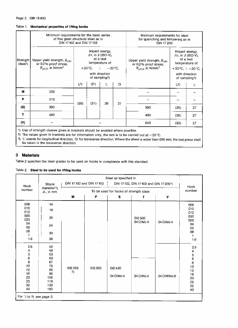
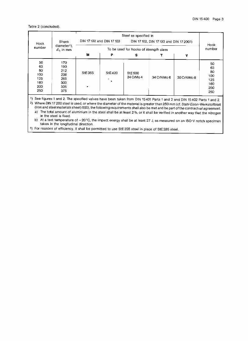
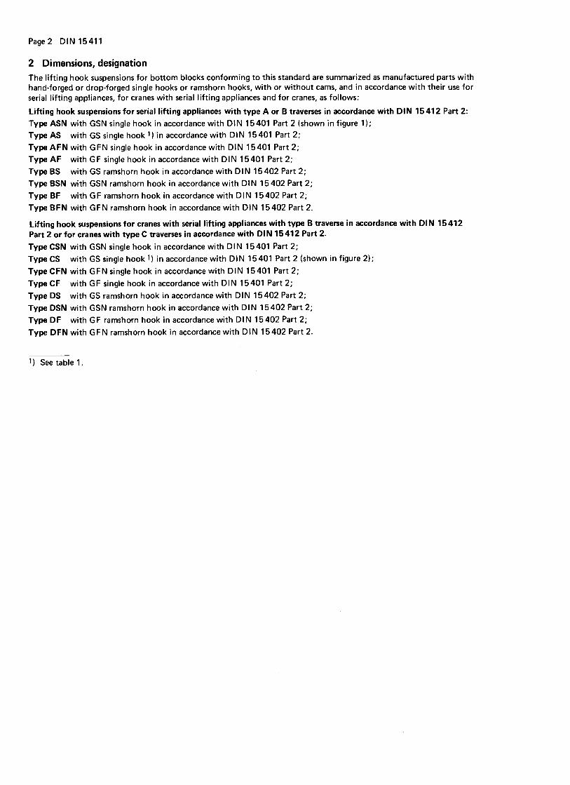
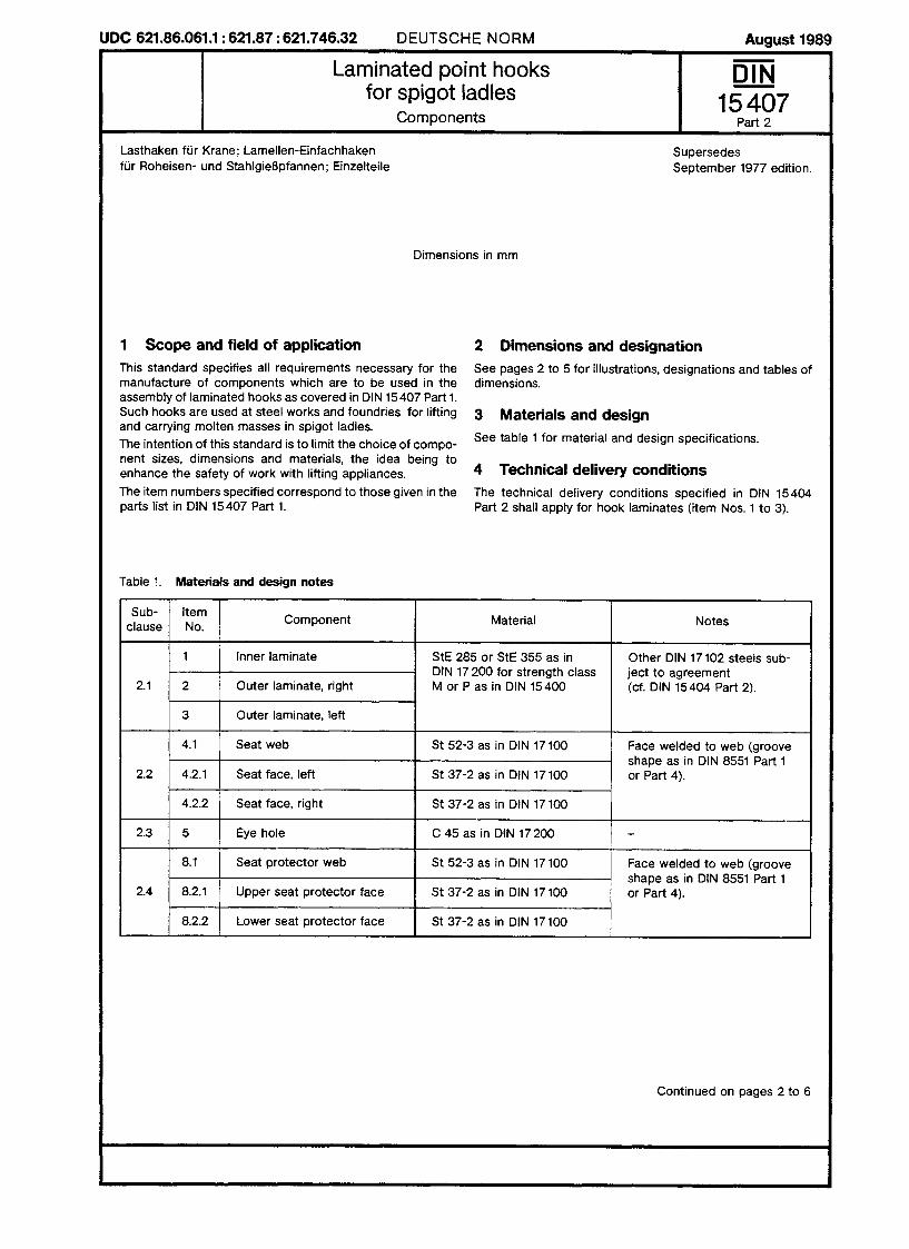
StandardsLoad carrying devicesLifting gear
History Product Program Guarany Quality management system CE-Conformity Recommendations concerning surface coating, corrosion protection and special materials
Lifting appliance and load handling device for general cargo General requirements DIN 15400 Lifting hooks – Materials, mechanical properties, lifting capacity and stresses 15404 part 1 Lifting hooks - Technical delivery conditions for forged shank hooks and work
certificate EN10204 (STB-sample) 15404 part 2 Lifting hooks - Technical delivery conditions for laminated hooks 15405 part 1 In-service inspection for forged shank hooks 15405 part 2 In-service inspection for laminated hooks
Forged Shank Hooks 15411 Lifting hook suspensions for bottom blocks STB Table of weights Single hooks 15401 part 1 Single hooks, unmachined parts 15401 part 2 Finished parts with threaded shank Ramshorn hooks 15402 part 1 Ramshorn hooks, unmachined parts 15402 part 2 Finished parts with threaded shank 15402 B STB Double hooks with hole and strengthening STB 21 002 Ramshorn shank hooks, shank with metric thread, with double lug and
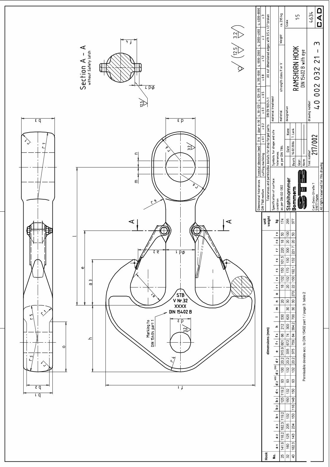
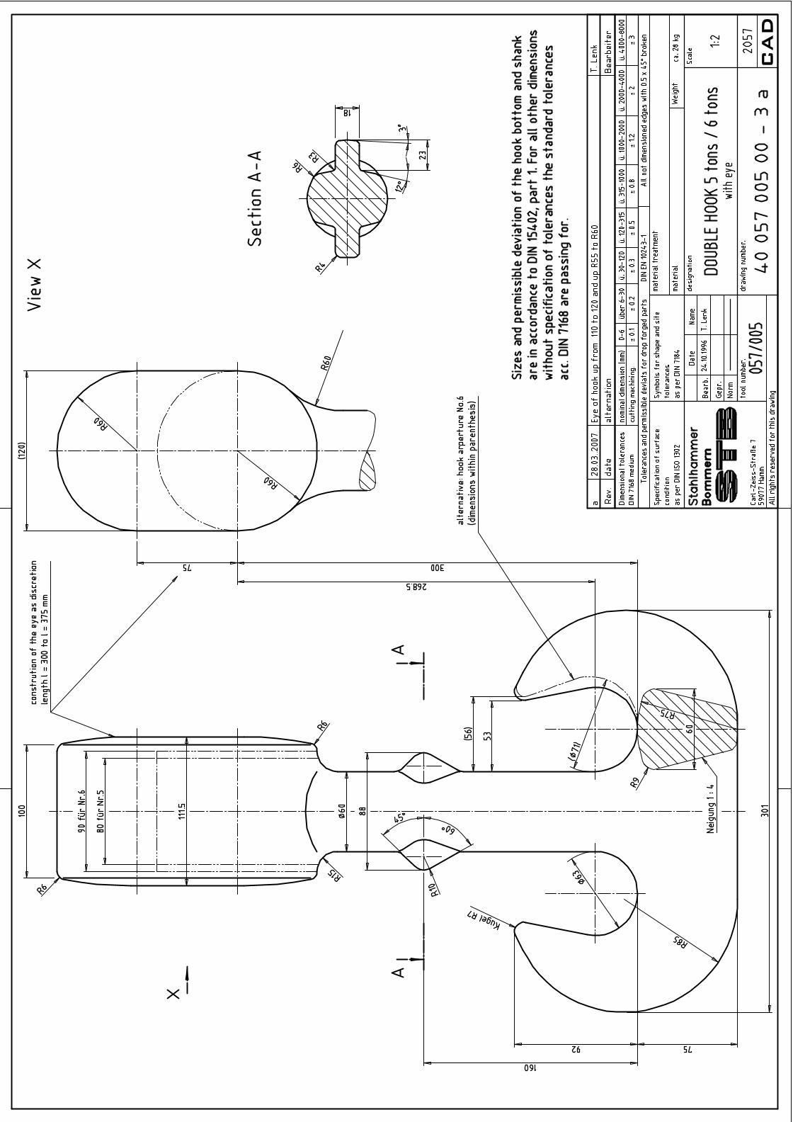
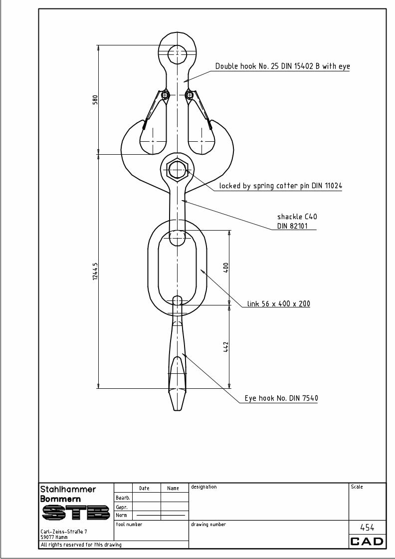
with eye DIN 82019 STB 21 057 Ramshorn hook with eye STB Double hook DIN 15402 B with eye and shackle joining and eye hook with master link STB Double hook 5 tons/6 tons with eye Knuckle Threads 15403 Knuckle Threads Cross pieces 15412 part 1 Cross pieces, unmachined parts 15412 part 2 Cross pieces, finished parts Lifting hook nuts 15413 Lifting hook nuts STB Lifting hook suspensions with axial cylindrical roller-bearing
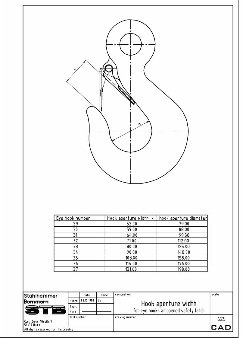
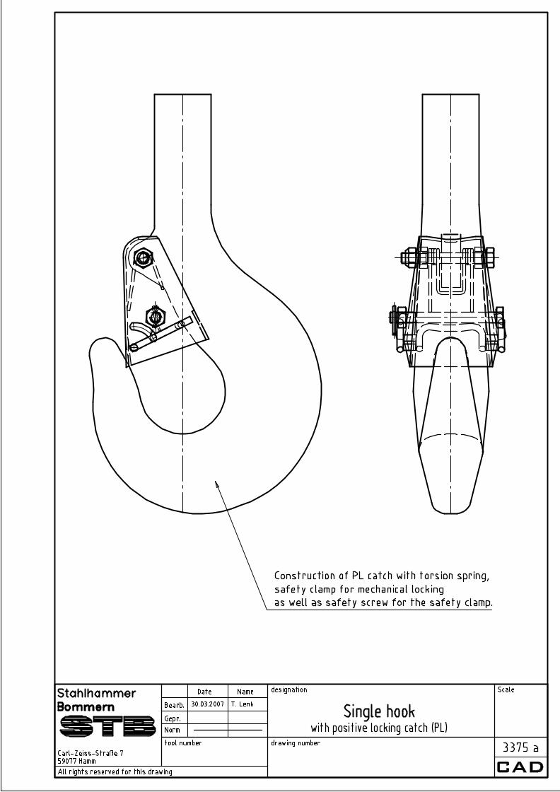
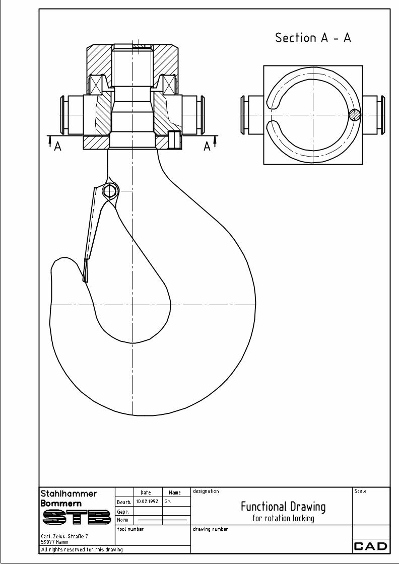
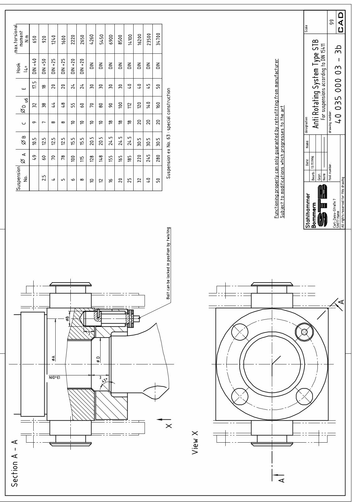
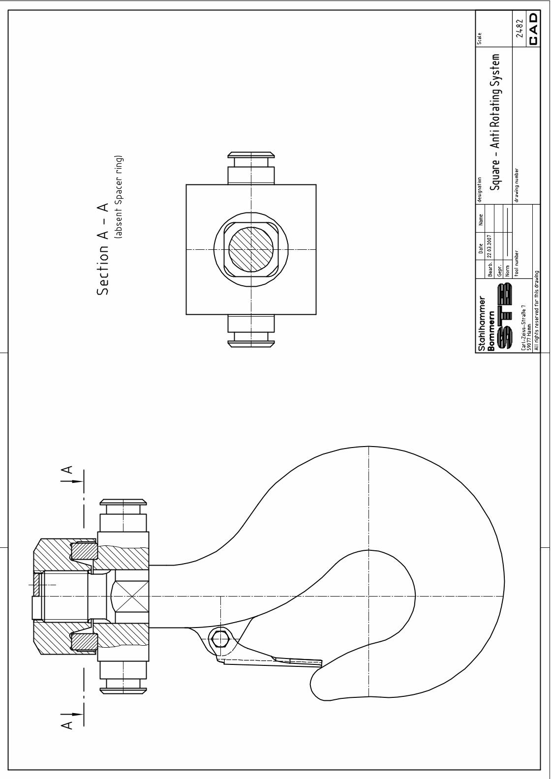
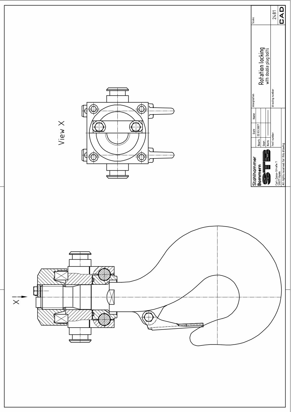
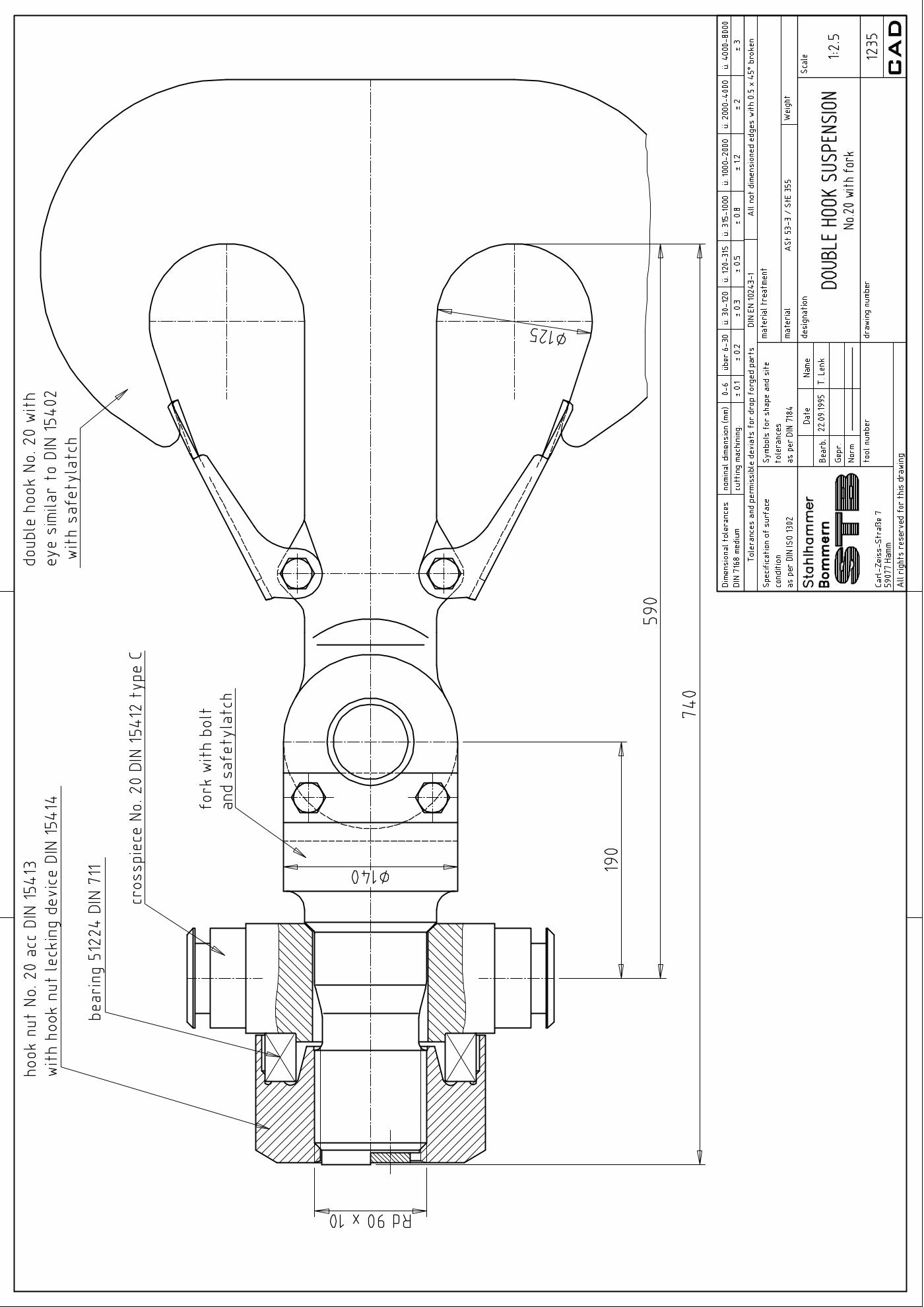
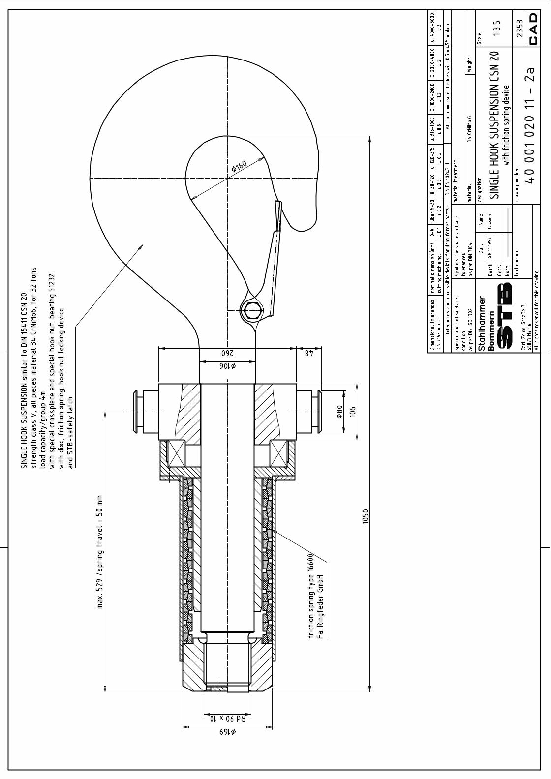
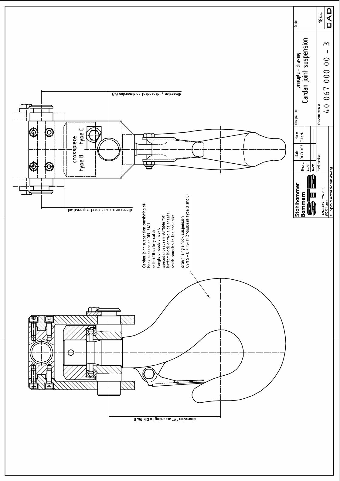
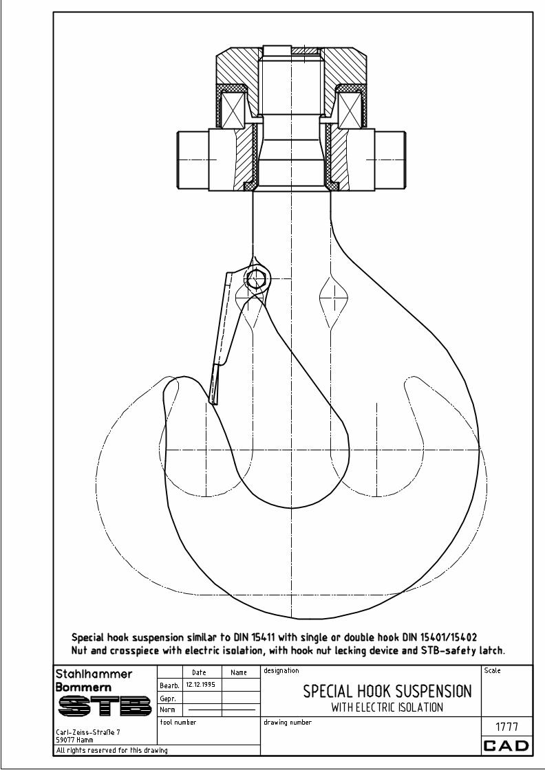
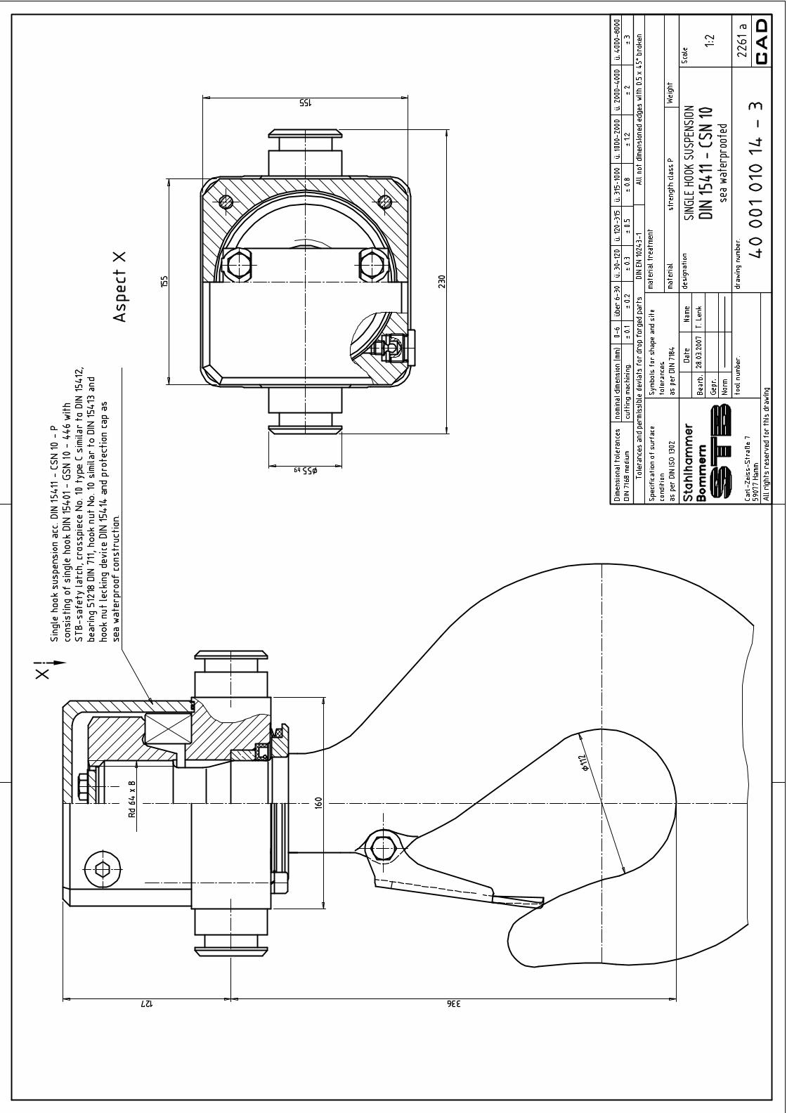
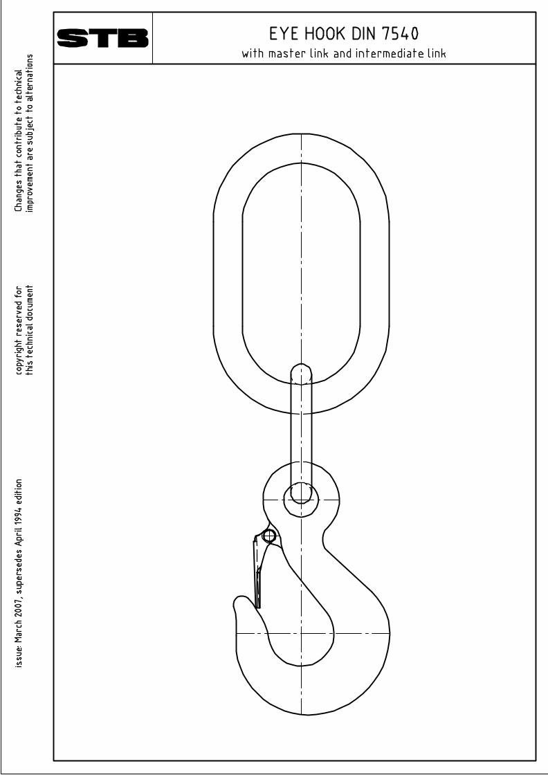
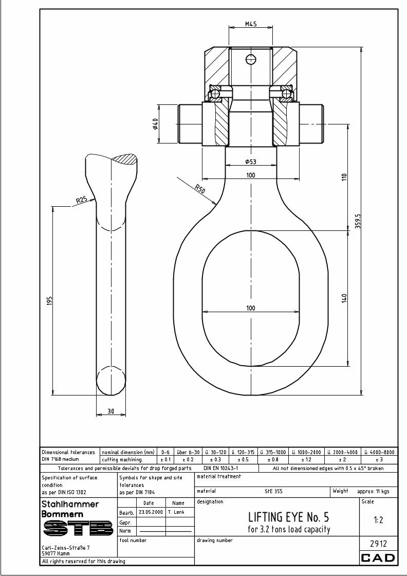
Securing plates 15414 Securing plates Measured length STB Measured length for single and double hooks Hook Safety Latches STB Hook Safety Latches STB dimension sheet for STB safety latches STB STB-safety latches for single and double hooks DIN 15401/15402 STB STB-safety latches for eye hooks DIN 7540 and cargo hooks DIN 82017 STB Hook aperture width with opened latch DIN 15401 STB Hook aperture width with opened latch DIN 15402 STB Hook aperture width with opened latch DIN 7540 STB Safety latch locking from dead weight STB Single hook with positive locking catch (PL) Rotation locking STB Rotation locking device (functional drawing) STB Anti-Rotating System STB Square box locking device STB Rotation locking with double plug bolts Bottom hook blocks 15408 Twin sheave bottom blocks 15409 Quadruple sheave bottom blocks 15410 Single and twin sheave bottom blocks for electric hoists Laminated point hooks 15407 part 1 Laminated point hooks, assembly and principal dimensions 15407 part 2 Laminated point hooks, components Forged eye hooks STB 21 005 Eye Hooks DIN 7540 Various lifting tools STB Double hook suspension No. 20 with fork STB Single hook suspension with friction spring device STB Cardan Joint Suspension STB Note for suspensions with electrical isolation STB suspensions with electrical isolation, functional drawing STB sea waterproofed hook suspension STB Double hook No. 25 for spreader facilitys STB Eye hook DIN 7540 with master link STB Lifting eye suspension
Swivels STB Swivels Cross hooks STB Cross hooks acc. to MM company standard (WN 21 061) STB Cross hook holder (WN 21 061-H) S-Hooks STB S-Hooks, sheets 1 and 2 Forgings for shipbuilding DIN 82006 Oval Eyes STB 21 006 Cargo Hooks DIN 82017 STB 21 006 N Cargo Hooks with nose DIN 82017 STB 21 065 Cargo Hook Swivels DIN 82018 STB 21 076 shackles DIN 82101 DIN 580 Collar eyebolts for lifting purposes a
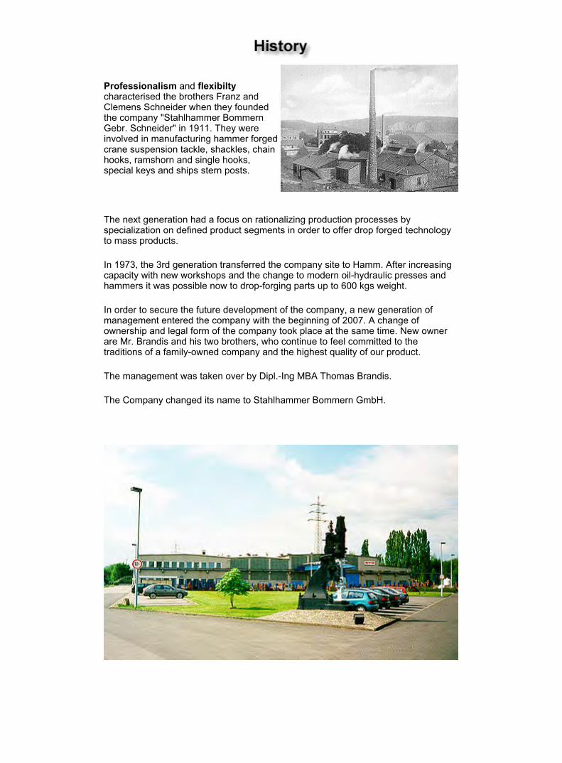
Professionalism and flexibilty characterised the brothers Franz and Clemens Schneider when they founded the company "Stahlhammer Bommern Gebr. Schneider" in 1911. They were involved in manufacturing hammer forged crane suspension tackle, shackles, chain hooks, ramshorn and single hooks, special keys and ships stern posts.
The next generation had a focus on rationalizing production processes by specialization on defined product segments in order to offer drop forged technology to mass products.
In 1973, the 3rd generation transferred the company site to Hamm. After increasing capacity with new workshops and the change to modern oil-hydraulic presses and hammers it was possible now to drop-forging parts up to 600 kgs weight.
In order to secure the future development of the company, a new generation of management entered the company with the beginning of 2007. A change of ownership and legal form of the company took place at the same time. New owner are Mr. Brandis and his two brothers, who continue to feel committed to the traditions of a family-owned company and the highest quality of our product.
The management was taken over by Dipl.-Ing MBA Thomas Brandis.
The Company changed its name to Stahlhammer Bommern GmbH.
Seite 1 von 2Firmenportrait
05.02.2010file://D:\My Catalog\stb_portrait_e.htm
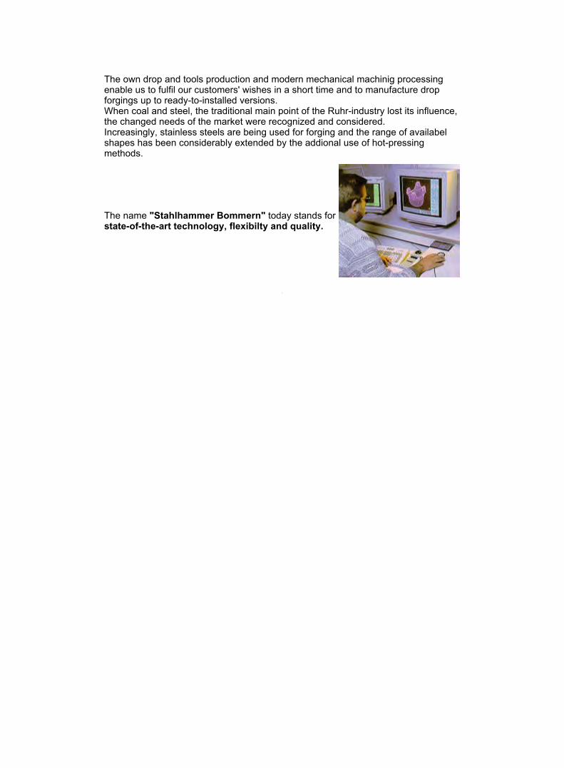
The own drop and tools production and modern mechanical machinig processing enable us to fulfil our customers' wishes in a short time and to manufacture drop forgings up to ready-to-installed versions. When coal and steel, the traditional main point of the Ruhr-industry lost its influence, the changed needs of the market were recognized and considered. Increasingly, stainless steels are being used for forging and the range of availabel shapes has been considerably extended by the addional use of hot-pressing methods.
The name "Stahlhammer Bommern" today stands for state-of-the-art technology, flexibilty and quality.
Seite 2 von 2Firmenportrait
05.02.2010file://D:\My Catalog\stb_portrait_e.htm
Supporting parts and lifting parts II
In consideration of the own standard specifications of big customers and according to the demands of our clients we developed universal useable standard-sizes for single and ramshorn hooks very early.
Since the year 1943 the DIN publicated standards which always kept up-to-date and have been readily accepted by other countries because of their near-to-the practice.
For our hook production we apply to the DIN standard.
Standard hooks can be delivered as rough forgings or as machined parts with knuckle direct from our plentiful stock. We offer hooks with special lengths of shank as same as hooks with abnormal dimensions.
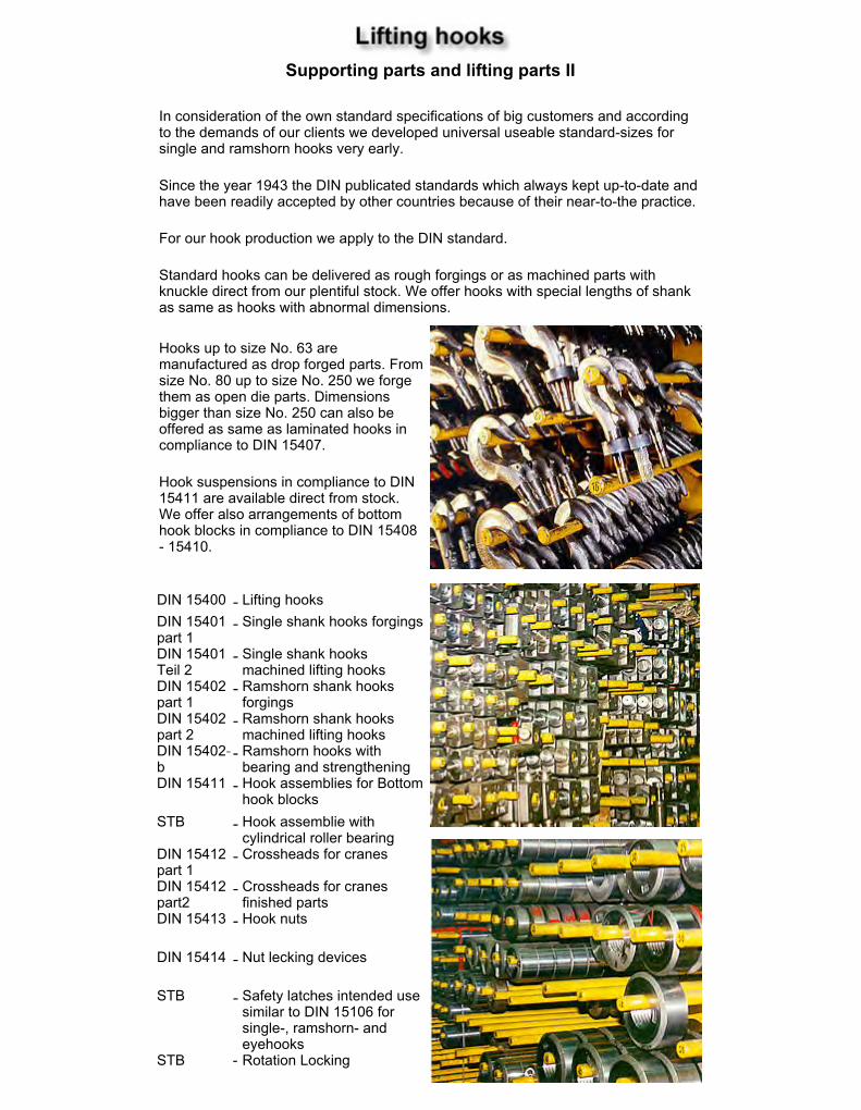
Hooks up to size No. 63 are manufactured as drop forged parts. From size No. 80 up to size No. 250 we forge them as open die parts. Dimensions bigger than size No. 250 can also be offered as same as laminated hooks in compliance to DIN 15407.
Hook suspensions in compliance to DIN 15411 are available direct from stock. We offer also arrangements of bottom hook blocks in compliance to DIN 15408 - 15410.
DIN 15400 - Lifting hooksDIN 15401 part 1
- Single shank hooks forgings
DIN 15401 Teil 2
- Single shank hooks machined lifting hooks
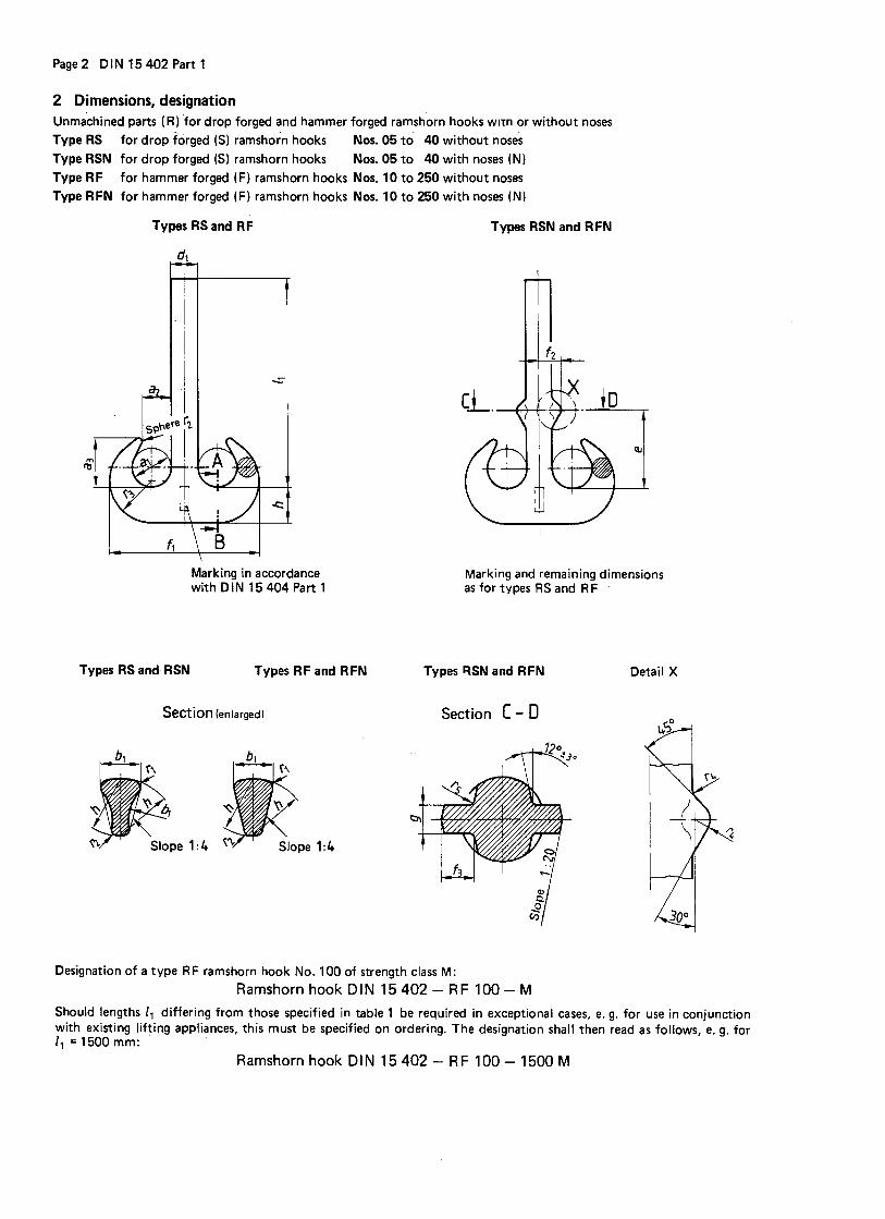
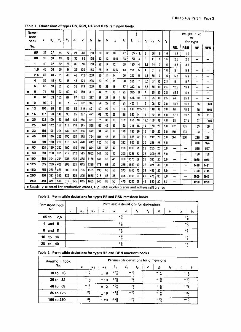
DIN 15402 part 1
- Ramshorn shank hooks forgings
DIN 15402 part 2
- Ramshorn shank hooks machined lifting hooks
DIN 15402-b
- Ramshorn hooks with bearing and strengthening
DIN 15411 -
Hook assemblies for Bottom hook blocks
STB - Hook assemblie with cylindrical roller bearing
DIN 15412 part 1
- Crossheads for cranes
DIN 15412 part2
- Crossheads for cranes finished parts
DIN 15413 -
Hook nuts
DIN 15414 -
Nut lecking devices
STB - Safety latches intended use similar to DIN 15106 for single-, ramshorn- and eyehooks
STB - Rotation Locking
Seite 1 von 3STB - Gesenk- und Freiformschmiede
05.02.2010file://D:\My Catalog\stb_lasthaken_e.htm
Supporting parts and lifting parts II
Forged hooks with eye
DIN 7540 Eye hooks STB Joining for chainsSTB Electrical isolated hook
assembleSTB Eyehooks in compliance to
TH- and MM-standards Other forged hooks
DIN STB Cross-hooks acc. to
MM-standardSTB Holding device for cross-
hooksSTB C-HooksSTB S-Hooks15407 part 1
Laminated single hooks in compliance to DIN 15407, part 1
15407 part 2
Laminated single hooks in compliance to DIN 15407, component parts, part 2
Hook tackles
DIN STB Eyehead-doublehook with
joining for shackle and eye-hook with suspending link
STB Swivel hooks
Liftings for bulk goods Grabs
DIN
STB Special construction
Fixing devices
DIN 5688 Chain slings with end linksSTB Chain slings with eyehook
DIN 7540 one- or multi-lineSTB Special hook for spreader chain
or special use
Forgins for shipbuilding
DIN82006 Oval eye head fittings82017 Cargo hooks 82017-N
Cargo hooks with nose
82018 Cargo hooks swivels82019 Ramshorn shank hooks with
metric thread/double lug/eyeSTB Ramshorn hook No.25 for
spreader works82024 Round eye plates82101 Shackles
Seite 2 von 3STB - Gesenk- und Freiformschmiede
05.02.2010file://D:\My Catalog\stb_lasthaken_e.htm
Bottom hook blocks
DIN 15408 Bottom hook block with two
sheaves15410 Bottom hook block for
electric hoists Chain- and hook-cross piece
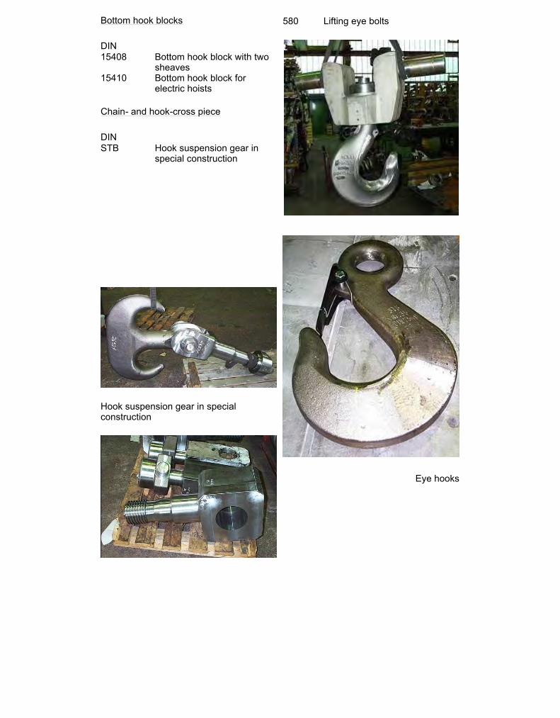
DIN STB Hook suspension gear in
special construction
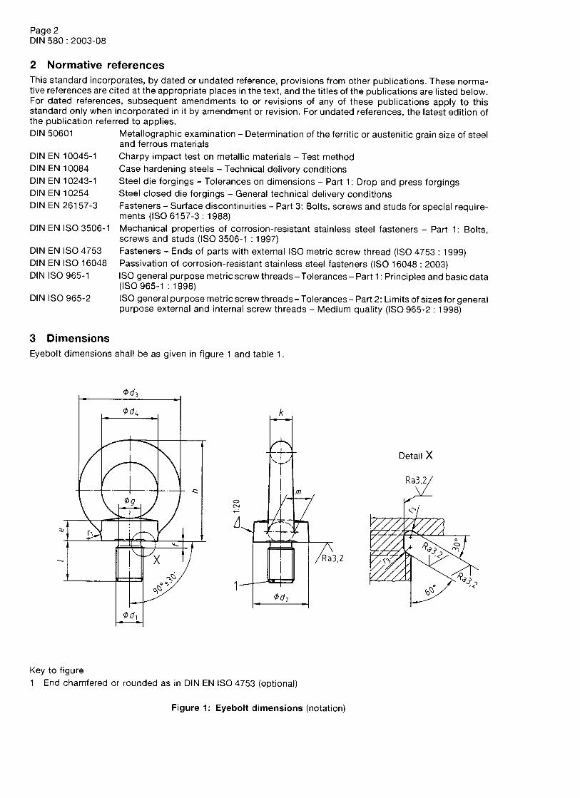
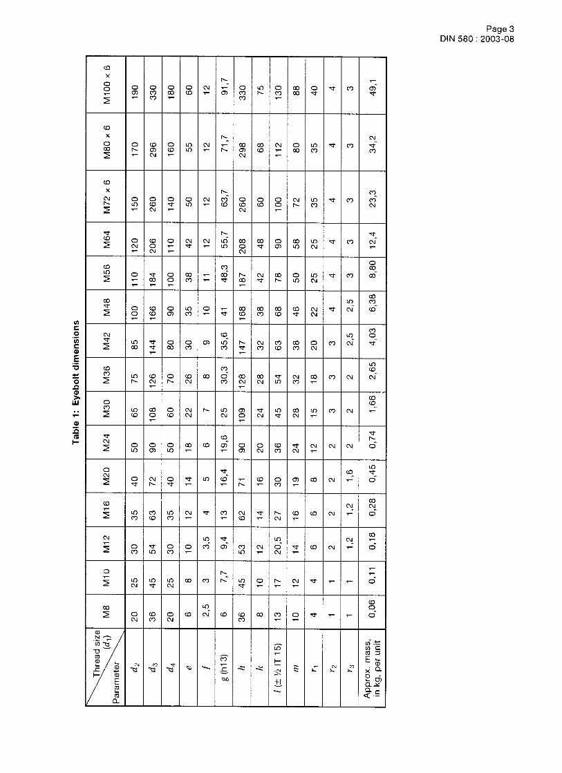
580 Lifting eye bolts
Hook suspension gear in special construction
Eye hooks
Seite 3 von 3STB - Gesenk- und Freiformschmiede
05.02.2010file://D:\My Catalog\stb_lasthaken_e.htm
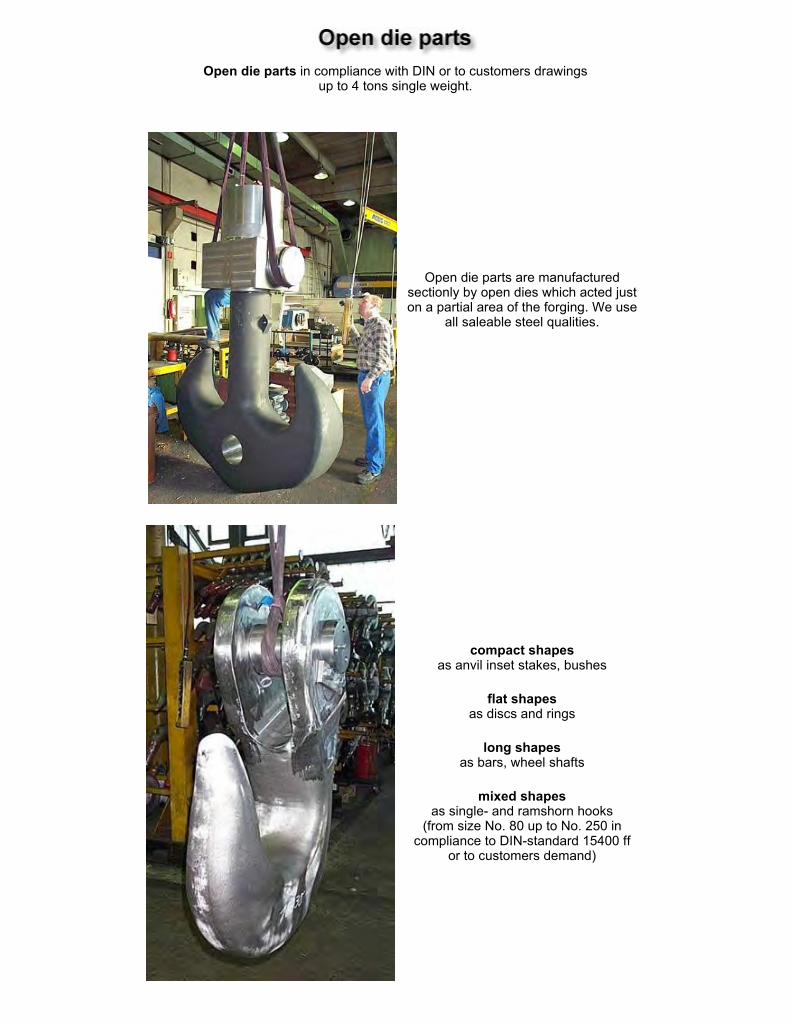
Open die parts in compliance with DIN or to customers drawings
up to 4 tons single weight.
Open die parts are manufactured sectionly by open dies which acted just on a partial area of the forging. We use
all saleable steel qualities.
compact shapes as anvil inset stakes, bushes
flat shapes as discs and rings
long shapes as bars, wheel shafts
mixed shapes as single- and ramshorn hooks
(from size No. 80 up to No. 250 in compliance to DIN-standard 15400 ff
or to customers demand)
Seite 1 von 2Untitled Document
05.02.2010file://D:\My Catalog\stb_freiform_e.htm
Seite 2 von 2Untitled Document
05.02.2010file://D:\My Catalog\stb_freiform_e.htm
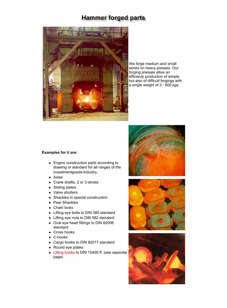
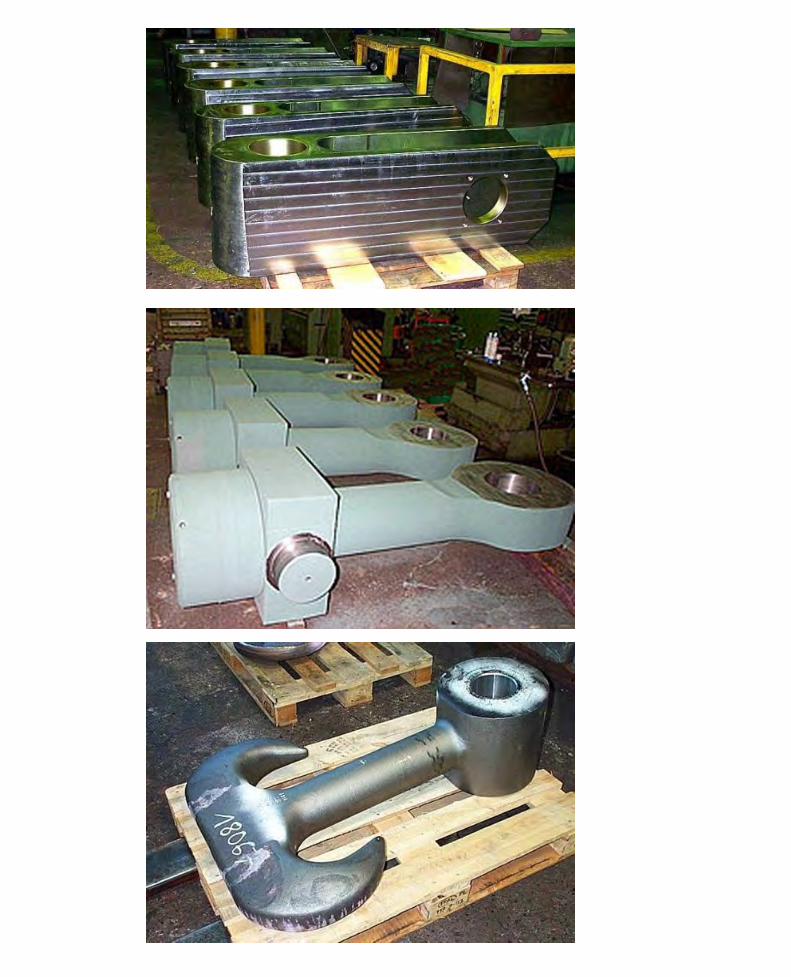
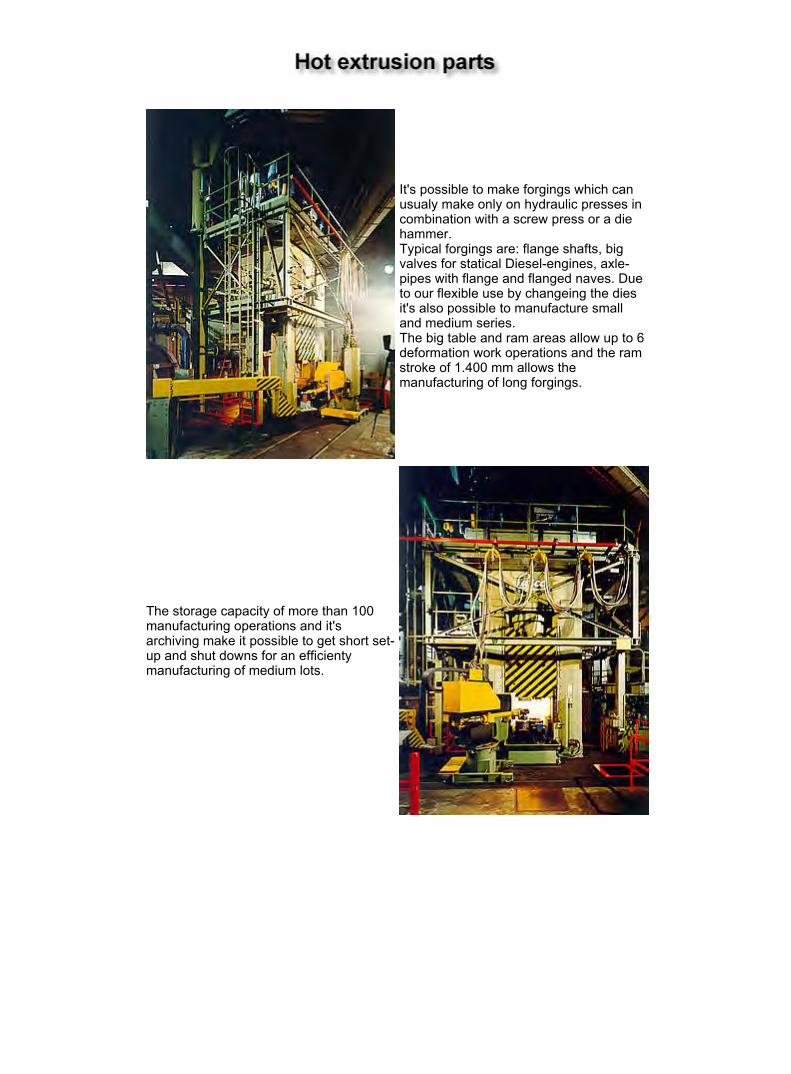
We forge medium and small series on heavy presses. Our forging presses allow an efficienty production of simple but also of difficult forgings with a single weight of 3 - 600 kgs.
Examples for it are:
Engine construction parts according to drawing or standard for all ranges of the investmentgoods-industry. Axles Crank shafts, 2 or 3-stroke Sliding plates Valve shutters Shackles in special construction Pear Shackles Chain locks Lifting eye bolts to DIN 580 standard Lifting eye nuts to DIN 582 standard Oval eye head fittings to DIN 82006 standard Cross hooks C-hooks Cargo hooks to DIN 82017 standard Round eye plates Lifting hooks to DIN 15400 ff. (see seperate page)
Seite 1 von 1Untitled Document
28.01.2010file://D:\STB-Homepage\stb_gesenkschmiede_e.htm
It's possible to make forgings which can usualy make only on hydraulic presses in combination with a screw press or a die hammer. Typical forgings are: flange shafts, big valves for statical Diesel-engines, axle-pipes with flange and flanged naves. Due to our flexible use by changeing the dies it's also possible to manufacture small and medium series. The big table and ram areas allow up to 6 deformation work operations and the ram stroke of 1.400 mm allows the manufacturing of long forgings.
The storage capacity of more than 100 manufacturing operations and it's archiving make it possible to get short set-up and shut downs for an efficienty manufacturing of medium lots.
Seite 1 von 2Produktübersicht
28.01.2010file://D:\STB-Homepage\stb_warmfliess_e.htm
7
Guaranty
We herewith certify, that our quality system conforms to the standard
EN ISO 9001:2008
and that our forged hooks for hoisting devices comply with the mechanical properties, materials, load capacities and defined tensions according to DIN 15400 and following standards. Furthermore we certify that the production process, the geometrical form and the dimensions meet the particular standards as well as the engineering specifications for delivery of forged hooks. Similar all known accident protections regulations are met.
All properties of the hooks according chapter 4.1 – 4.5 are confirmed in our product certificate according EN 10204-3.1.
For hooks which are allocated to strength categories and drive group according DIN 15400 table 3 and with a proven supervision of the use of forged hooks according to DIN 15404 Part 1, in compliance with the accident protection regulations UVV (VBG 9a) § 40 + § 42 and ZH 1/27.4.4 we offer a guaranty of
1 Year.
The mechanical properties of the material for our hooks are within the endurance limit. To meet the mentioned accident protection regulations we can offer a guaranty only from one inspection interval to the next inspection. After this interval the hook has to get an inspection according to DIN 15405 Part 1. Accordingly accident protection execution regulation § 26 UVV apply. Following § 27 UVV a check of the hook for bending up and wear off has to be done at the beginning of every work shift.
59077 Hamm, 01.June 2009
Stahlhammer Bommern GmbH
8
QUALITY MANAGEMENT SYSTEM
Since the begin of the year 1995 we're in the possession of the certificate No. Q-5827 by which "Det Norske Vertitas Zertifizierung GmbH" certifies that the Quality Management System of our company is subject to compliance with the rules for classification and DIN ISO 9002/EN290025, 5.90.
It's actuality is secured by internal audits and annual audits of DNV. Hereby it's proved and guarantied that our deliveries and services will be done by seasonable actions according to EN ISO 9001:2008.
The testing of materials comprises non-destructive tests as ultrasonic testing, magnetic powder testing and dye penetration testing also as destructive tests like hardness testing and metallographic examinations.
Checking of tolerances and allowances will be carry out according to DIN EN 10243-1 and material tests in compliance to EN 10204 or by appointment.
We're qualified by all renowned inspection companies at home and abroad and besides we guarantee with our name.
CE-Conformity CE-Identification The CE-Identification is not a particular feature for product quality or performance of a producer. It only indicates the opinion of the producer that its machine complies to the EG machine directives. The CE-Identification is neither a quality feature nor a quality certification which is granted after a test procedure or theoretical prove from an independent certification company or public authority. The retention or the improvement of the security level in the member countries is the main intention of the EG machine directives. The existing national regulations for security and health to protect against danger, which come from machines, should be brought into line in order to allow a free exchange of machines without lowering the protection levels in the individual member countries. The CE-Identification replaces the previous product certification standards for building and equipment of the public environmental authority, the Accident Prevention & Insurance Association, the German TÜV and others. The same applies for product certification situations in other countries of the European Union (ISPESI, APAVE, etc.), which are deprived of the legal basis of product certification for building and equipment. The certification of installation situations (safety clearance etc.) will stay in the responsibility of the national security authority. The occupational safety authority are allowed to pull a product with a CE identification out of the market or to forbid the initial operation only if danger for persons, animals or goods exists. The measure entails a compulsory procedure by the European Commission in Brussels and must be decided by the European Court of Justice. Missing knowledge of the EG machine directives can shake up the operators due to deviating arguments of the different producers. For all machines, which fall under the EG machine directives, a CE-Conformity declaration has to be certified by each producer which has to be provided with each delivered machine. Components which are functionally usable only together with other components (e.g. hooks) a producer certification is required which is provided with each component. On each machine the following minimum information that must be readable and un-erasable must be provided:
• Name and address of producer • the CE-Identification • Identification of product code and type of product • if necessary: serial number
If the producer designs a machine to be used in an explosive atmosphere this indication (e.g. Protection symbols) must also provided on the machine. According to the design of the machine all for the security indispensable information have to be provided on the machine (e.g. the load capacity on hoisting devices or cranes). Hook suspensions which belong to the category of exchangeable equipment according to the EG machine directives have to be labelled as follows:
• Name of Producer • maximum load capacity • own weight • the CE-Identification
For lifting accessories with components like cable where labelling is not possible a plate or other device with the above mentioned information has to be fixed to the lifting accessory. The information must be in good readability and be fixed at a place where it can not be erased through wearout and where the stability of the lifting accessory is not reduced. CE Symbol The CE-Symbol consists of the following symbol: CE Minimum height is 5 Millimetres. A combination with other symbols like e.g. the GS-Symbol is possible under certain circumstances.
Recommendations concerning surface coating, corrosion protection and special materials. Due to the surface crack test load hooks and corresponding components are delivered with a sandblasted or blank surface. Under atmospheric influence all untreated parts will start corrosion after a short period of time. By using synthetic resin paint (for example in color RAL 9005) for the surface which will not be mechanically processed and through application of corrosion protection oil (for example Dekydrat 180) for mechanically processed surfaces the corrosion can be avoided. For transport and storage protection different anticorrosives are used. Also plastic or paint based coatings offer protection for a limited period of time (normally less than 2 years). Furthermore galvanic coatings are possible for example based on zinc. The unavoidable temperature of 500 °Celsius in the zinc basin can be detrimental to the mechanical properties of the parts due to the tempering effect. This negative effect occurs significantly only with small cross sections and with material which has a low resistance against tempering. The bigger risk with the galvanic processing as well as with hot-galvanising lies in hydrogen embrittlement. Already at the pre-treatment pickling process and during the coating process hydrogen diffusion can not totally be eliminated. Therefore we recommend as after-treatment a hydrogen diffusion annealing (dependant on size of cross-section ca. 4h at 222°C). Through this after-treatment possible reduced toughness properties of the drop forged parts or - in the worst case - brittle fracture can be avoided (please note DIN 50969). For use in sea water or for parts in the chemical industry or equivalent industries drop forged parts can be offered in stainless steel materials (for example 4401 or equivalent). Those materials are nearly antimagnetic and have less tendency to spark formation. For use in mining or in other explosive areas we recommend to use hard nickel plated parts (around 550 HV). Copper plating does not achieve the required durability. Forging spark free materials which conform to strength class M respective P is possible with complex forging processes and due to low production volume only recommendable in special cases. We offer all processes of special metal treatment in cooperation with business partners.
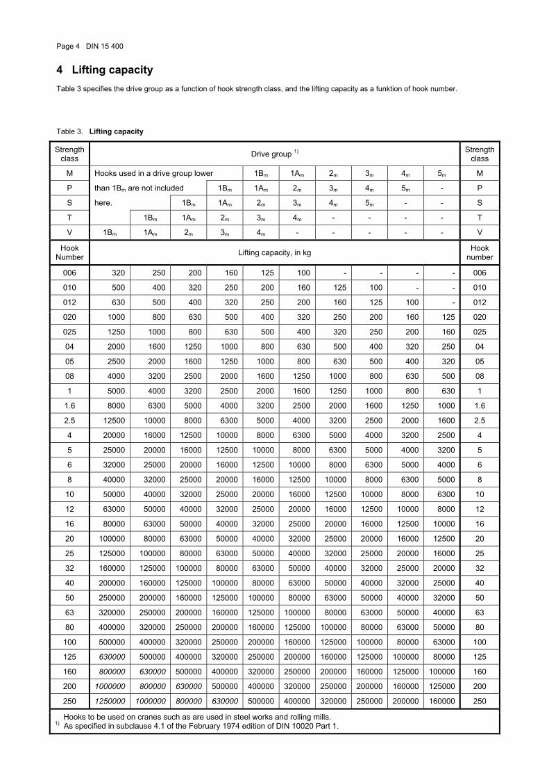
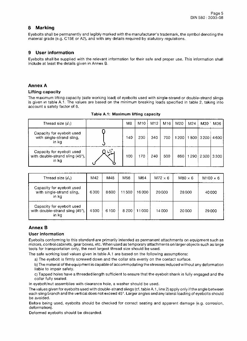
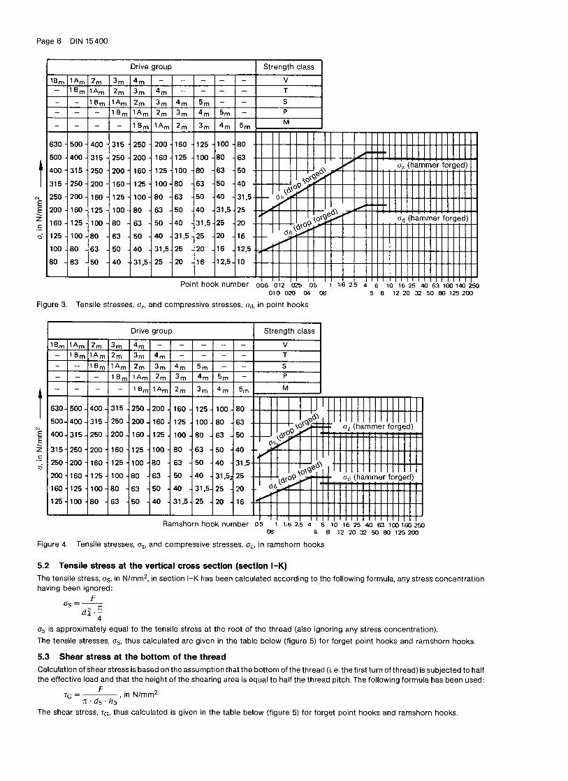
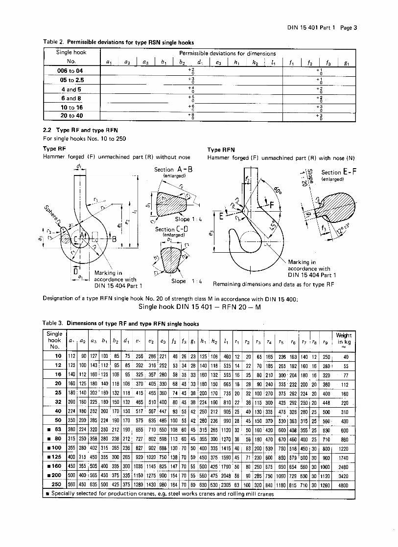
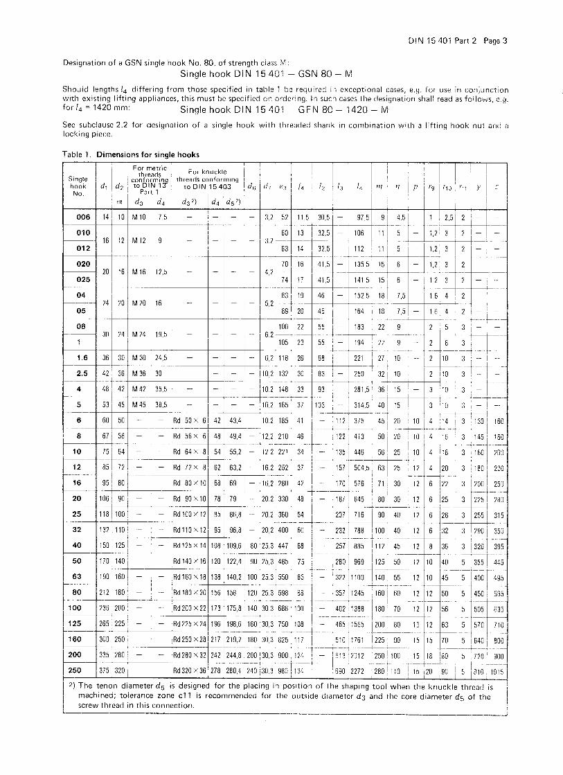
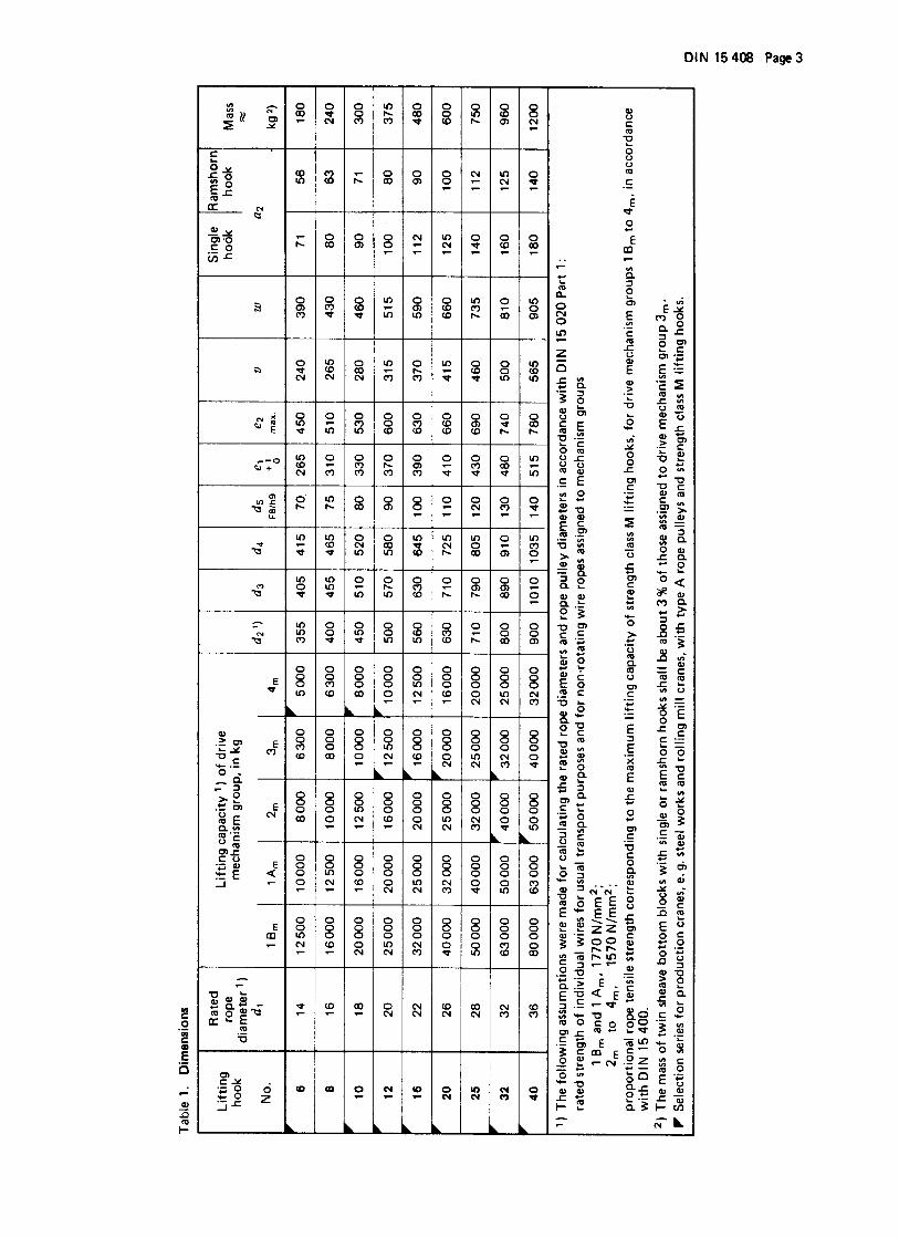
Page 4 DIN 15 400 4 Lifting capacity Table 3 specifies the drive group as a function of hook strength class, and the lifting capacity as a funktion of hook number. Table 3. Lifting capacity
Strength class Drive group 1) Strength
class
M Hooks used in a drive group lower 1Bm 1Am 2m 3m 4m 5m M
P than 1Bm are not included 1Bm 1Am 2m 3m 4m 5m - P
S here. 1Bm 1Am 2m 3m 4m 5m - - S
T 1Bm 1Am 2m 3m 4m - - - - T
V 1Bm 1Am 2m 3m 4m - - - - - V
Hook Number Lifting capacity, in kg Hook
number
006 320 250 200 160 125 100 - - - - 006
010 500 400 320 250 200 160 125 100 - - 010
012 630 500 400 320 250 200 160 125 100 - 012
020 1000 800 630 500 400 320 250 200 160 125 020
025 1250 1000 800 630 500 400 320 250 200 160 025
04 2000 1600 1250 1000 800 630 500 400 320 250 04
05 2500 2000 1600 1250 1000 800 630 500 400 320 05
08 4000 3200 2500 2000 1600 1250 1000 800 630 500 08
1 5000 4000 3200 2500 2000 1600 1250 1000 800 630 1
1.6 8000 6300 5000 4000 3200 2500 2000 1600 1250 1000 1.6
2.5 12500 10000 8000 6300 5000 4000 3200 2500 2000 1600 2.5
4 20000 16000 12500 10000 8000 6300 5000 4000 3200 2500 4
5 25000 20000 16000 12500 10000 8000 6300 5000 4000 3200 5
6 32000 25000 20000 16000 12500 10000 8000 6300 5000 4000 6
8 40000 32000 25000 20000 16000 12500 10000 8000 6300 5000 8
10 50000 40000 32000 25000 20000 16000 12500 10000 8000 6300 10
12 63000 50000 40000 32000 25000 20000 16000 12500 10000 8000 12
16 80000 63000 50000 40000 32000 25000 20000 16000 12500 10000 16
20 100000 80000 63000 50000 40000 32000 25000 20000 16000 12500 20
25 125000 100000 80000 63000 50000 40000 32000 25000 20000 16000 25
32 160000 125000 100000 80000 63000 50000 40000 32000 25000 20000 32
40 200000 160000 125000 100000 80000 63000 50000 40000 32000 25000 40
50 250000 200000 160000 125000 100000 80000 63000 50000 40000 32000 50
63 320000 250000 200000 160000 125000 100000 80000 63000 50000 40000 63
80 400000 320000 250000 200000 160000 125000 100000 80000 63000 50000 80
100 500000 400000 320000 250000 200000 160000 125000 100000 80000 63000 100
125 630000 500000 400000 320000 250000 200000 160000 125000 100000 80000 125
160 800000 630000 500000 400000 320000 250000 200000 160000 125000 100000 160
200 1000000 800000 630000 500000 400000 320000 250000 200000 160000 125000 200
250 1250000 1000000 800000 630000 500000 400000 320000 250000 200000 160000 250
Hooks to be used on cranes such as are used in steel works and rolling mills. 1) As specified in subclause 4.1 of the February 1974 edition of DIN 10020 Part 1.
GmbH
Thomas BrandisGmbH
xxxxxxxxxxxxx
This standard includes safety requirements within the meaning of the “Gesetz über technischeArbeitsmittel” (Technical Equipment Safety Law) This standard has been prepared with theHauptverband der gewerblichen Berufgenossenchaften e.V, Central office for accident prevention andoccupational medicine, Bonn.
Start of validity:
This standard is valid from March 1st, 1979
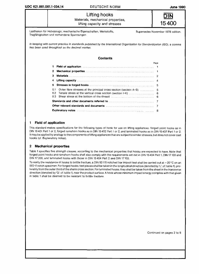
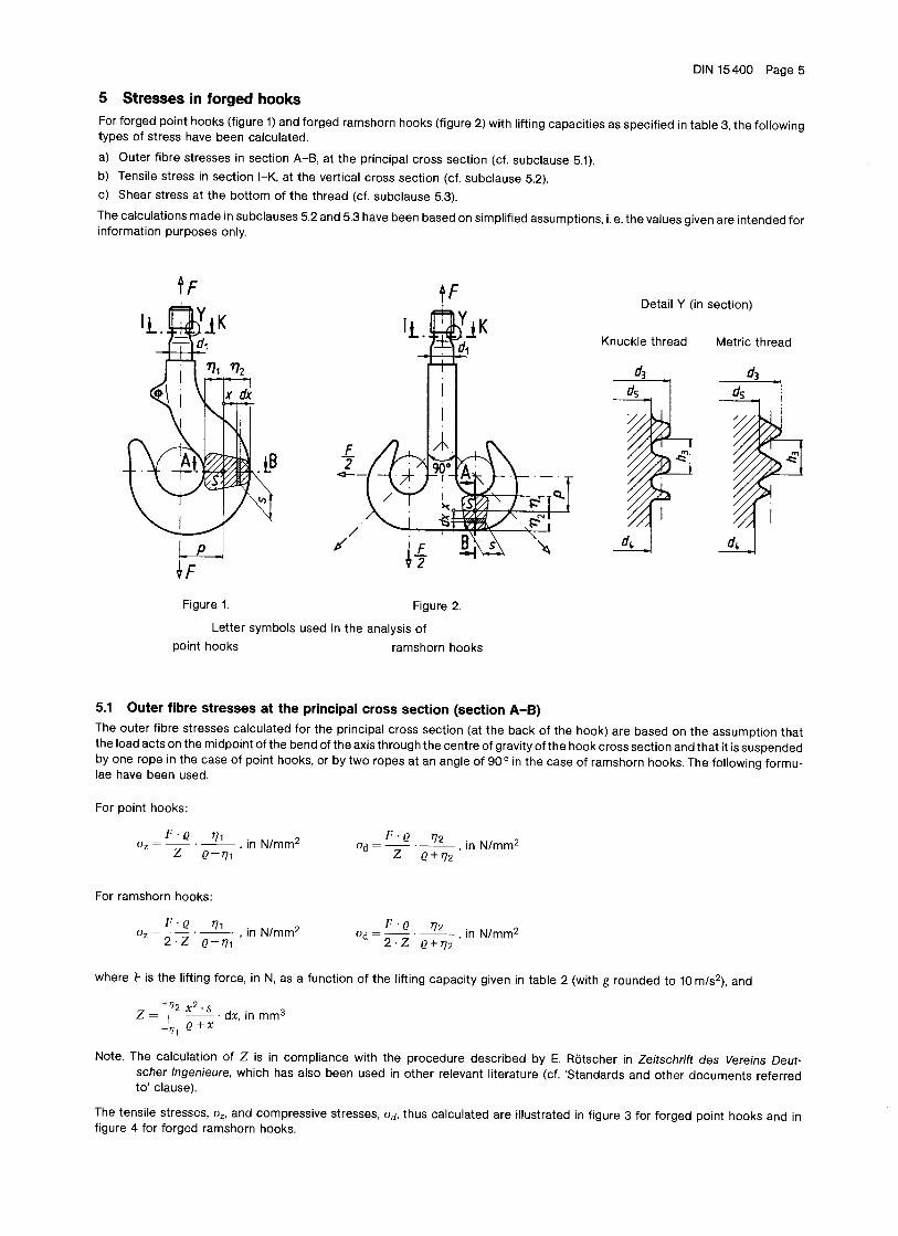
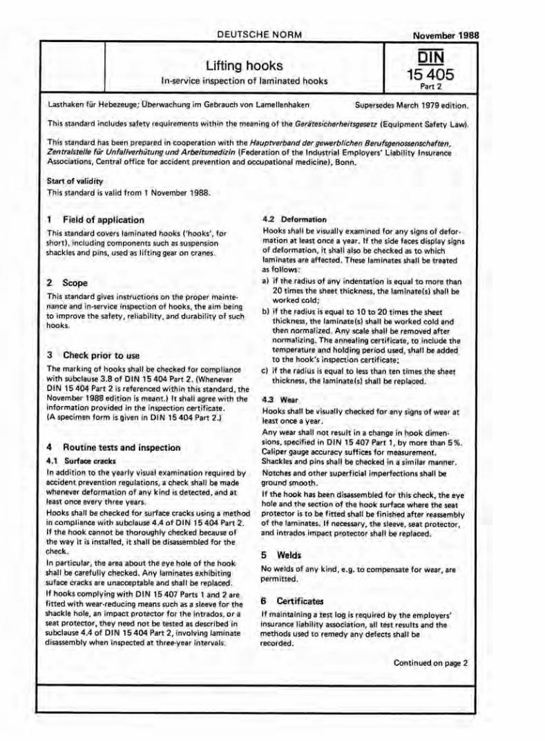
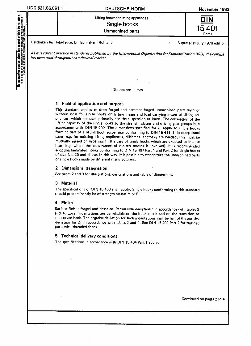
1 Field of application
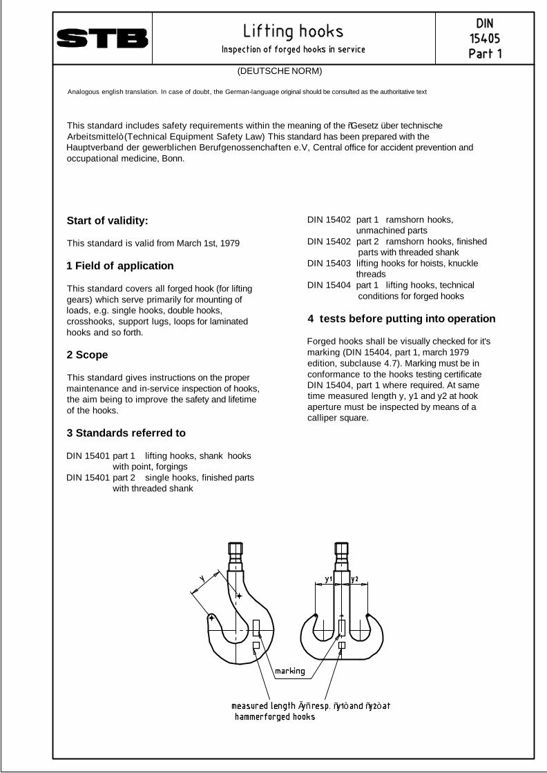
This standard covers all forged hook (for liftinggears) which serve primarily for mounting ofloads, e.g. single hooks, double hooks,crosshooks, support lugs, loops for laminatedhooks and so forth.
2 Scope
This standard gives instructions on the propermaintenance and in-service inspection of hooks,the aim being to improve the safety and lifetimeof the hooks.
3 Standards referred to
DIN 15401 part 1 lifting hooks, shank hooks with point, forgingsDIN 15401 part 2 single hooks, finished parts with threaded shank
DIN 15402 part 1 ramshorn hooks, unmachined partsDIN 15402 part 2 ramshorn hooks, finished parts with threaded shankDIN 15403 lifting hooks for hoists, knuckle threadsDIN 15404 part 1 lifting hooks, technical conditions for forged hooks
4 tests before putting into operation
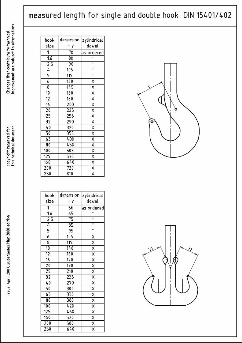
Forged hooks shall be visually checked for it'smarking (DIN 15404, part 1, march 1979edition, subclause 4.7). Marking must be inconformance to the hooks testing certificateDIN 15404, part 1 where required. At sametime measured length y, y1 and y2 at hookaperture must be inspected by means of acalliper square.
„ “ “ ” “ ”
(DEUTSCHE NORM)
Analogous english translation. In case of doubt, the German-language original should be consulted as the authoritative text
5 Routine tests and observations
This is to avoid accidents by in time detectingof defects at forged hooks. Testing results andmeasures to fix them must be mentioned intothe testing documents (if its directed to keeptab on a test book by the employer's liabilityinsurance association).
5.1 Deformation
hooks shall be examined for any sings ofdeformation, especially on hook aperture andshank at least of once a year. For hooks acc.to DIN 15401 part 1 and 2 and DIN 15402 part1 and 2 a visually examination of the hookaperture up to size No. 5 is sufficing. By morethan 10 % widening of the admissibledimension of the hook aperture (a2) acc. to DIN15401 part 1 and DIN 15402 part 2, hooksmust be replaced. All other hooks and loopsfor laminated hooks must be replaced ifdeformation in use exceeds 10 % of the hooknominal sizes. If deformation is detected, testsaccording to subclause 5.2 must be done, too.
5.2 Surface cracks
If deformations acc. to subclause 5.1 aredetected, testing for surface cracks must beexecuted also (by an applicable procedure) orthe hook must be replaced. If it's not possibleto execute this test because the hook isbuilt-in, it must be disassembled. The surfacemust be prepared to that effect that a clearidentification of surface cracks is possible.Damages and surface cracks can me removedfree of notches as far as function, admissibledeviations and admissible wear do admit.Hooks which have non-admissible surfacecracks must be replaced
5.3 Wear
For single and double hooks takes effect, thatmore than 5 % wear of dimension h2 acc. toDIN 15401 part 1 and h according to DIN15402 part 1 isn't allowed. For all other typesof hooks this stipulation is to construedanalogues. Wear doesn't proceed 5 % of thenominal sizes. Caliper gauge accuracy sufficesfor measurement . Notches and othersuperficial imperfections shall be groundsmooth. Wear at hook nuts and locking piecesis non-admissible.
5.4 Corrosion
If the influence of corrosion can't be avoidthread and machined shank must be inspectedto corrosion notches. If reworking of corrosionnotches is necessary, inspection acc. to DIN15404, part 1 (edition march 1979, subclause5.3) must be done. A new hook nut must bemanufactured in case of non-admissible axialplay.
Thread pattern acc. to DIN 15403 must beobserved. If minor diameter d1 acc. to DIN15401 or DIN 15402 is dropping below of 5 %,hook must me replaced.
6 Welds
No welds of any kind, e. g. to compensate forwear, are permitted.
7 Certificates
All tests and all test results and the methodsused to remedy any defects shall be recorded.
Page 2, DIN 15405 part 1
48
49
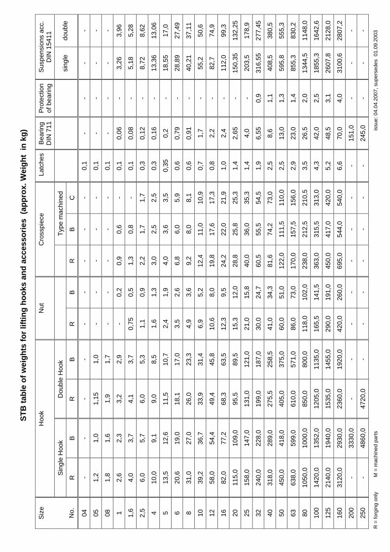
STB
tabl
e of
wei
ghts
for l
iftin
g ho
oks
and
acce
ssor
ies
(app
rox.
Wei
ght
in k
g)
H
ook
Nut
C
ross
piec
e La
tche
sB
earin
g D
IN 7
11
Pro
tect
ion
of b
earin
g Su
spen
sion
s ac
c.
DIN
154
11
Sin
gle
Hoo
k D
oubl
e H
ook
Type
mac
hine
d
Size
No.
R
B
R
B
R
B
R
B
C
si
ngle
do
uble
04
- -
- -
- -
- -
- 0,
1 -
- -
-
05
1,2
1,0
1,15
1,
0 -
- -
- -
0,1
- -
- -
08
1,8
1,6
1,9
1,7
- -
- -
- 0,
1 -
- -
-
1 2,
6 2,
3 3,
2 2,
9 -
0,2
0,9
0,6
- 0,
1 0,
06
- 3,
26
3,96
1,6
4,0
3,7
4,1
3,7
0,75
0,
5 1,
3 0,
8 -
0,1
0,08
-
5,18
5,
28
2,5
6,0
5,7
6,0
5,3
1,1
0,9
2,2
1,7
1,7
0,3
0,12
-
8,72
8,
62
4 10
,0
9,1
9,0
8,5
1,6
1,3
3,0
2,5
2,5
0,3
0,16
-
13,3
6 13
,06
5 13
,5
12,6
11
,5
10,7
2,
4 1,
9 4,
0 3,
6 3,
5 0,
35
0,2
- 18
,55
17,0
6 20
,6
19,0
18
,1
17,0
3,
5 2,
6 6,
8 6,
0 5,
9 0,
6 0,
79
- 28
,89
27,4
9
8 31
,0
27,0
26
,0
23,3
4,
9 3,
6 9,
2 8,
0 8,
1 0,
6 0,
91
- 40
,21
37,1
1
10
39,2
36
,7
33,9
31
,4
6,9
5,2
12,4
11
,0
10,9
0,
7 1,
7 -
55,2
50
,6
12
58,0
54
,4
49,4
45
,8
10,6
8,
0 19
,8
17,6
17
,3
0,8
2,2
- 82
,7
74,9
16
82,0
77
,2
68,3
63
,5
12,3
9,
5 24
,2
22,0
21
,9
1,0
2,4
- 11
2,0
99,3
20
115,
0 10
9,0
95,5
89
,5
15,3
12
,0
28,8
25
,8
25,3
1,
4 2,
65
- 15
0,35
13
2,25
25
158,
0 14
7,0
131,
0 12
1,0
21,0
15
,8
40,0
36
,0
35,3
1,
4 4,
0 -
203,
5 17
8,9
32
240,
0 22
8,0
199,
0 18
7,0
30,0
24
,7
60,5
55
,5
54,5
1,
9 6,
55
0,9
316,
55
277,
45
40
318,
0 28
9,0
275,
5 25
8,5
41,0
34
,3
81,6
74
,2
73,0
2,
5 8,
6 1,
1 40
8,5
380,
5
50
450,
0 41
8,0
405,
0 37
5,0
60,0
51
,0
122,
0 11
1,5
110,
0 2,
5 13
,0
1,3
595,
8 55
5,3
63
638,
0 59
9,0
610,
0 57
1,0
86,0
73
,0
170,
0 15
7,5
156,
0 2,
9 23
,0
1,4
855,
3 83
0,2
80
1050
,0
1000
,0
850,
0 80
0,0
118,
0 10
2,0
238,
0 21
2,5
210,
5 3,
5 26
,5
2,0
1344
,5
1148
,0
100
1420
,0
1352
,0
1205
,0
1135
,0
165,
5 14
1,5
363,
0 31
5,5
313,
0 4,
3 42
,0
2,5
1855
,3
1642
,6
125
2140
,0
1940
,0
1535
,0
1455
,0
290,
0 19
1,0
450,
0 41
7,0
420,
0 5,
2 48
,5
3,1
2607
,8
2128
,0
160
3120
,0
2930
,0
2360
,0
1920
,0
420,
0 26
0,0
695,
0 54
4,0
540,
0 6,
6 70
,0
4,0
3100
,6
2807
,2
200
- 33
30,0
-
- -
- -
- -
- 15
1,0
- -
-
250
- 48
60,0
47
20,0
-
- -
- -
- -
245,
0 -
- -
R =
forg
ing
only
M
= m
achi
ned
parts
iss
ue: 0
4.04
.200
7, s
uper
sede
s 0
1.09
.200
3
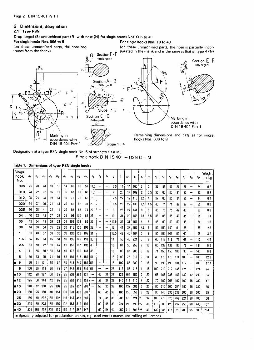
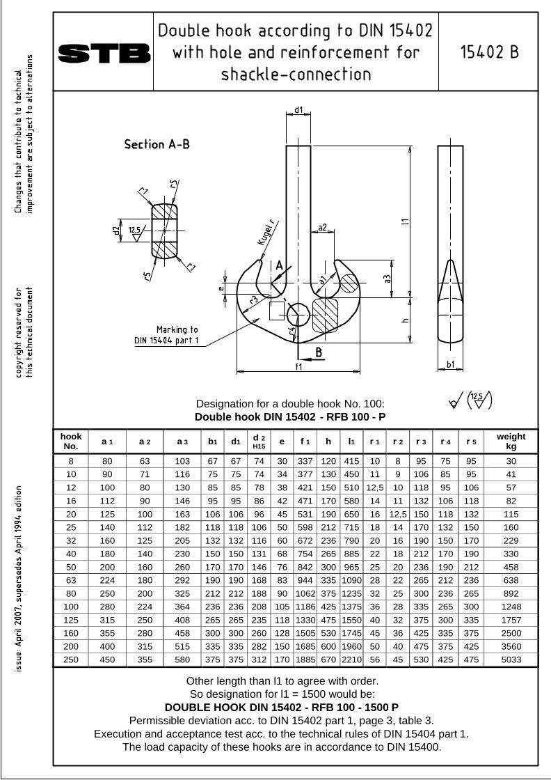
hook No. a 1 a 2 a 3 b1 d1 d 2
H15 e f 1 h l1 r 1 r 2 r 3 r 4 r 5 weight kg
8 80 63 103 67 67 74 30 337 120 415 10 8 95 75 95 30 10 90 71 116 75 75 74 34 377 130 450 11 9 106 85 95 41 12 100 80 130 85 85 78 38 421 150 510 12,5 10 118 95 106 57 16 112 90 146 95 95 86 42 471 170 580 14 11 132 106 118 82 20 125 100 163 106 106 96 45 531 190 650 16 12,5 150 118 132 115 25 140 112 182 118 118 106 50 598 212 715 18 14 170 132 150 160 32 160 125 205 132 132 116 60 672 236 790 20 16 190 150 170 229 40 180 140 230 150 150 131 68 754 265 885 22 18 212 170 190 330 50 200 160 260 170 170 146 76 842 300 965 25 20 236 190 212 458 63 224 180 292 190 190 168 83 944 335 1090 28 22 265 212 236 638 80 250 200 325 212 212 188 90 1062 375 1235 32 25 300 236 265 892
100 280 224 364 236 236 208 105 1186 425 1375 36 28 335 265 300 1248 125 315 250 408 265 265 235 118 1330 475 1550 40 32 375 300 335 1757 160 355 280 458 300 300 260 128 1505 530 1745 45 36 425 335 375 2500 200 400 315 515 335 335 282 150 1685 600 1960 50 40 475 375 425 3560 250 450 355 580 375 375 312 170 1885 670 2210 56 45 530 425 475 5033
Designation for a double hook No. 100:Double hook DIN 15402 - RFB 100 - P
Other length than l1 to agree with order.So designation for l1 = 1500 would be:
DOUBLE HOOK DIN 15402 - RFB 100 - 1500 PPermissible deviation acc. to DIN 15402 part 1, page 3, table 3.
Execution and acceptance test acc. to the technical rules of DIN 15404 part 1.The load capacity of these hooks are in accordance to DIN 15400.
1 Field of application and purpose
This standard applies to double hooks which are used for handling equipments on ships.Hooks type A with thread are common for direct joining of the hooks with lower blockcrossbeam of the cargo purchase.Hooks type B with fork are needed by interposition of an eye for swivels acc. to DIN 82010.Hooks type C with eye are needed by interposition of a fork for swivels acc. to DIN 82008.
This standard applies for double hooks (drop or hammer forged parts) with and without nose,on lifting means and load carrying means of lifting appliances, which are used primarily forthe suspension of loads. The correlation of the lifting capacity of the double hooks to thestrength classes and driving gear groups is in accordance to DIN 15400. They are assigned tothe nominal sizes of this standard.
Page 1, DIN 82 019
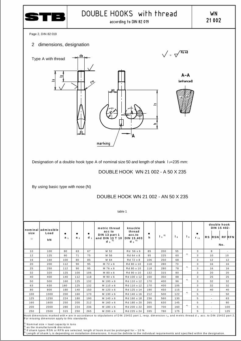
dou b le h ook D IN 1 5 4 02 -
R S
R S N
R F
R FN
nom in al s ize
1 )
ad m issib le Loa d
k N
• a 1
• a 2
• d 1
m etric th re ad ac c to
D IN 1 3 p art 1 and DIN 13 T 10
d 3 2 )
knu ck le th re ad ac c.to
D IN 1 5 40 3 d 3
2 )
• h
l 1 3 )
l 2
l 3
• r 1 1
No .
10 100 80 63 67 M 52 R d 56 x 6 85 200 55 3 8 -
12 125 90 71 75 M 56 R d 64 x 8 95 225 60 3 10 10
16 160 100 80 85 M 64 R d 72 x 8 106 250 68
4 )
3 12 12 20 200 112 90 95 M 72 x 6 R d 80 x 10 118 280 73 3 16 16
25 250 112 90 95 M 76 x 6 R d 80 x 10 118 280 78 3 16 16
32 320 125 100 106 M 80 x 6 R d 90 x 10 132 315 80
4 )
3 20 20 40 400 140 112 118 M 90 x 6 R d 100 x 12 150 350 88 3 25 25
50 500 160 125 132 M 100 x 6 R d 110 x 12 170 400 96 3 32 32
63 630 160 125 132 M 110 x 6 R d 110 x 12 170 400 105
4 )
3 32 32 80 800 180 140 150 M 120 x 6 R d 125 x 14 190 450 115 3 40 40
100 1000 200 160 170 M 130 x 6 R d 140 x 16 212 500 122 5 - 50
125 1250 224 180 190 M 140 x 6 R d 160 x 18 236 560 130
4 )
5 - 63 160 1600 250 200 212 M 160 x 6 R d 180 x 20 265 630 145 5 - 80
200 2000 280 224 236 M 180 x 6 R d 200 x 22 300 700 160 5 - 100
250 2500 315 250 265 M 200 x 6 R d 225 x 24 335 780 175
4 )
5 - 125
H ook d im ens ions m arked w ith • a re in acc ordance to s tipu lations o f D IN 154 02 part 1, res p. d im ens ion r11 and m e tric th read d 3 acc . to D IN 154 02 pa rt 2. F or m is sing dim ens ion apply to th is s tandards. 1 ) N om inal s ize = load c apac ity in to ns 2 ) as the m anu fac ture r ’s disc re tion 3 ) If shan k types R S N or R F N are se lec ted, length of hoo k m ust be pro longed fo r ∼ 1 0 % 4 ) Leng th of sh ank l3 is depending on ins tal la tion d im ens ions. It m us t be definite to the ind ividual requ irem ents and s pec ified w ithin the des ignation .
table 1
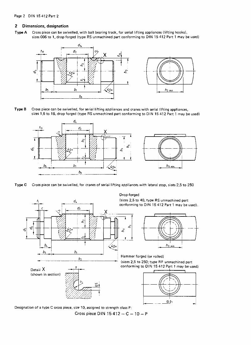
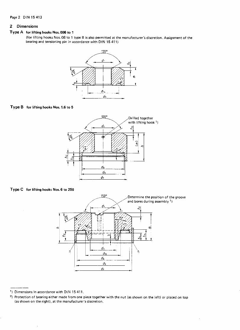
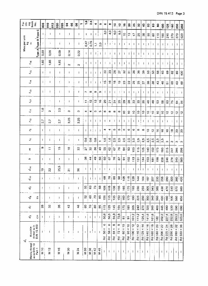
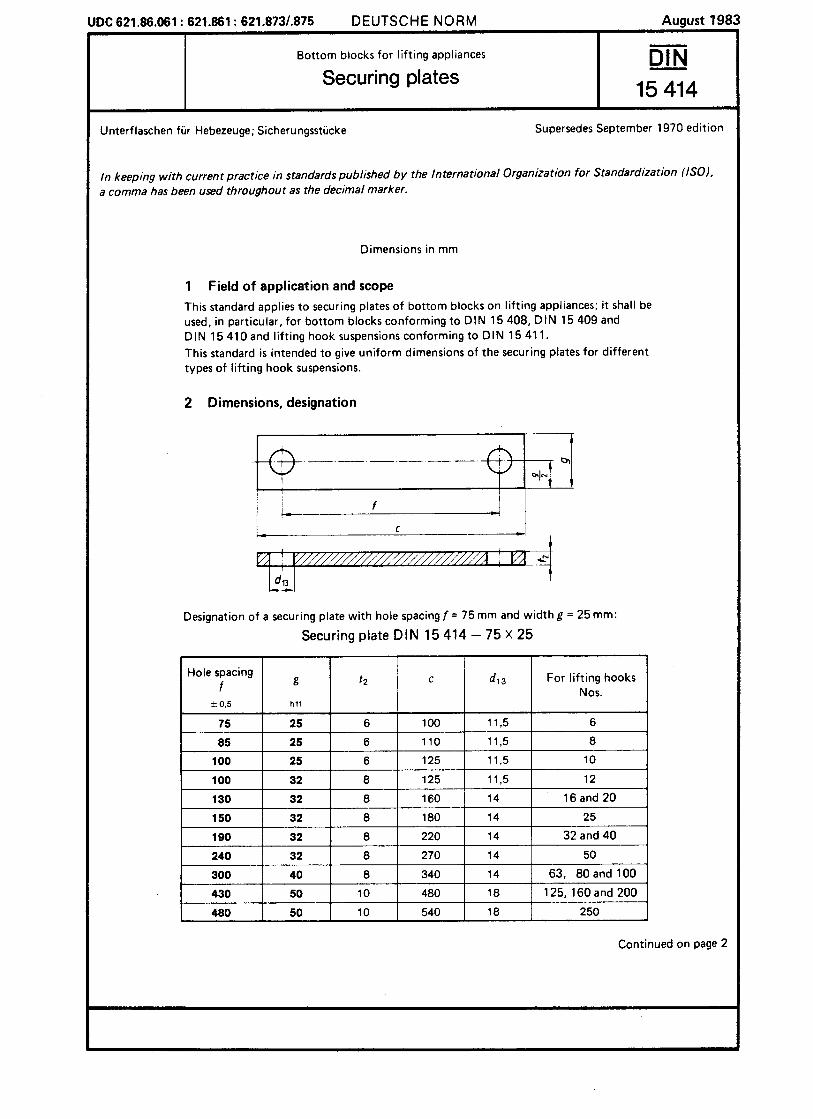
2 dimensions, designation
Type A with thread
Designation of a double hook type A of nominal size 50 and length of shank l 3=235 mm:
DOUBLE HOOK WN 21 002 - A 50 X 235
By using basic type with nose (N)
DOUBLE HOOK WN 21 002 - AN 50 X 235
=
Page 2, DIN 82 019
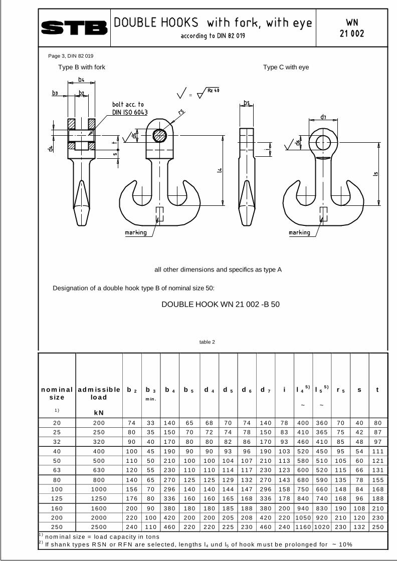
n om in al s iz e
1 )
a d m is sib le lo a d
k N
b 2
b 3
m in .
b 4
b 5
d 4
d 5
d 6
d 7 i
l 4 5 )
~
l 5 5 )
~
r 5
s
t
20 200 74 33 140 65 68 70 74 140 78 400 36 0 70 40 80 25 250 80 35 150 70 72 74 78 150 83 410 365 75 42 87 32 320 90 40 170 80 80 82 86 170 93 460 41 0 85 48 97 40 400 100 45 190 90 90 93 96 190 103 520 45 0 95 54 111 50 500 110 50 210 100 100 104 107 210 113 580 51 0 105 60 121 63 630 120 55 230 110 110 114 117 230 123 600 52 0 115 66 131
80 800 140 65 270 125 125 129 132 270 143 680 59 0 135 78 155 100 1000 156 70 296 140 140 144 147 296 158 750 66 0 148 84 168 125 1250 176 80 336 160 160 165 168 336 178 840 74 0 168 96 188
160 1600 200 90 380 180 180 185 188 380 200 940 83 0 190 108 210 200 2000 220 100 420 200 200 205 208 420 220 1050 92 0 210 120 230 250 2500 240 110 460 220 220 225 230 460 240 1160 1020 230 132 250
1 ) nom ina l s ize = lo ad c apac ity in tons 2 ) If shan k types R S N or R F N are s e lec ted , leng ths l4 und l5 o f hook m us t be p ro longed fo r ~ 10%
table 2
Type B with fork Type C with eye
Designation of a double hook type B of nominal size 50:
DOUBLE HOOK WN 21 002 -B 50
=
all other dimensions and specifics as type A
Page 3, DIN 82 019
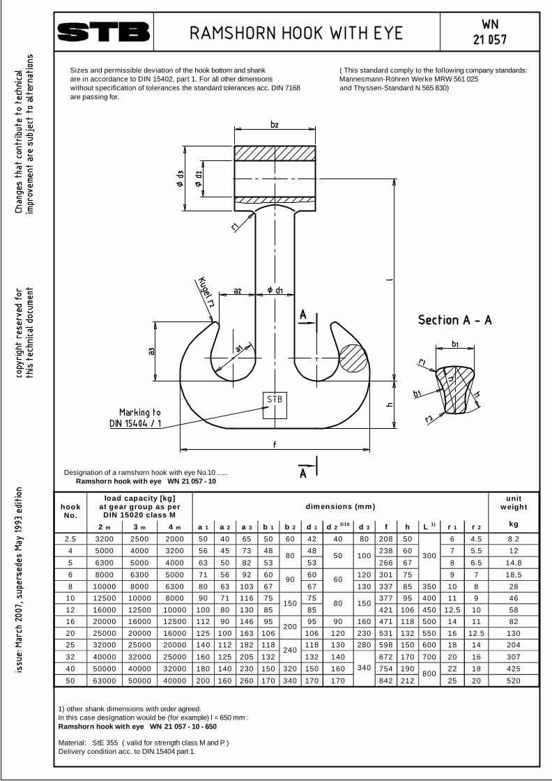
load capacity [kg] at gear group as per DIN 15020 class M
dimensions (mm) hook No.
2 m 3 m 4 m a 1 a 2 a 3 b 1 b 2 d 1 d 2 D10 d 3 f h L 1) r 1 r 2
unit weight
kg
2.5 3200 2500 2000 50 40 65 50 60 42 40 80 208 50 6 4.5 8.2 4 5000 4000 3200 56 45 73 48 48 238 60 7 5.5 12 5 6300 5000 4000 63 50 82 53
80 53
50 100 266 67 8 6.5 14.8
6 8000 6300 5000 71 56 92 60 60 120 301 75
300
9 7 18.5 8 10000 8000 6300 80 63 103 67
90 67
60 130 337 85 350 10 8 28
10 12500 10000 8000 90 71 116 75 75 377 95 400 11 9 46 12 16000 12500 10000 100 80 130 85
150 85
80 150 421 106 450 12.5 10 58
16 20000 16000 12500 112 90 146 95 95 90 160 471 118 500 14 11 82 20 25000 20000 16000 125 100 163 106
200 106 120 230 531 132 550 16 12.5 130
25 32000 25000 20000 140 112 182 118 118 130 280 598 150 600 18 14 204 32 40000 32000 25000 160 125 205 132
240 132 140 672 170 700 20 16 307
40 50000 40000 32000 180 140 230 150 320 150 160 754 190 22 18 425 50 63000 50000 40000 200 160 260 170 340 170 170
340
842 212 800
25 20 520
1) other shank dimensions with order agreed.In this case designation would be (for example) l = 650 mm :Ramshorn hook with eye WN 21 057 - 10 - 650
Sizes and permissible deviation of the hook bottom and shankare in accordance to DIN 15402, part 1. For all other dimensionswithout specification of tolerances the standard tolerances acc. DIN 7168are passing for.
( This standard comply to the following company standards:Mannesmann-Röhren Werke MRW 561 025and Thyssen-Standard N 565 830)
STB
Designation of a ramshorn hook with eye No.10 ......Ramshorn hook with eye WN 21 057 - 10
Material: StE 355 ( valid for strength class M and P )Delivery condition acc. to DIN 15404 part 1.
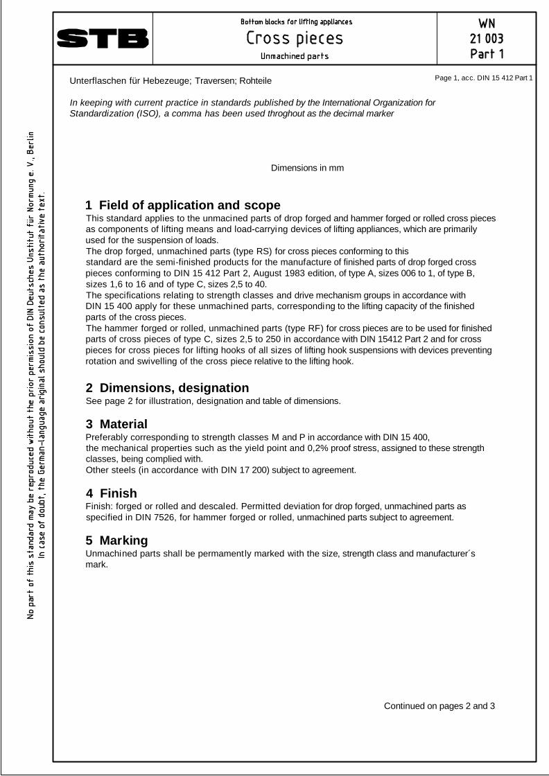
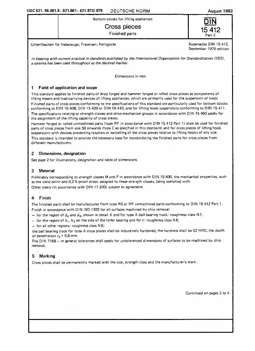
1 Field of application and scopeThis standard applies to the unmacined parts of drop forged and hammer forged or rolled cross piecesas components of lifting means and load-carrying devices of lifting appliances, which are primarilyused for the suspension of loads.The drop forged, unmachined parts (type RS) for cross pieces conforming to thisstandard are the semi-finished products for the manufacture of finished parts of drop forged crosspieces conforming to DIN 15 412 Part 2, August 1983 edition, of type A, sizes 006 to 1, of type B,sizes 1,6 to 16 and of type C, sizes 2,5 to 40.The specifications relating to strength classes and drive mechanism groups in accordance withDIN 15 400 apply for these unmachined parts, corresponding to the lifting capacity of the finishedparts of the cross pieces.The hammer forged or rolled, unmachined parts (type RF) for cross pieces are to be used for finishedparts of cross pieces of type C, sizes 2,5 to 250 in accordance with DIN 15412 Part 2 and for crosspieces for cross pieces for lifting hooks of all sizes of lifting hook suspensions with devices preventingrotation and swivelling of the cross piece relative to the lifting hook.
2 Dimensions, designationSee page 2 for illustration, designation and table of dimensions.
3 MaterialPreferably corresponding to strength classes M and P in accordance with DIN 15 400,the mechanical properties such as the yield point and 0,2% proof stress, assigned to these strengthclasses, being complied with.Other steels (in accordance with DIN 17 200) subject to agreement.
4 FinishFinish: forged or rolled and descaled. Permitted deviation for drop forged, unmachined parts asspecified in DIN 7526, for hammer forged or rolled, unmachined parts subject to agreement.
5 MarkingUnmachined parts shall be permamently marked with the size, strength class and manufacturer´smark.
Continued on pages 2 and 3
Unterflaschen für Hebezeuge; Traversen; Rohteile
In keeping with current practice in standards published by the International Organization forStandardization (ISO), a comma has been used throghout as the decimal marker
Dimensions in mm
Page 1, acc. DIN 15 412 Part 1
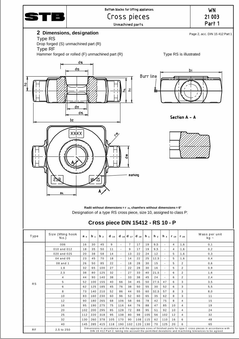
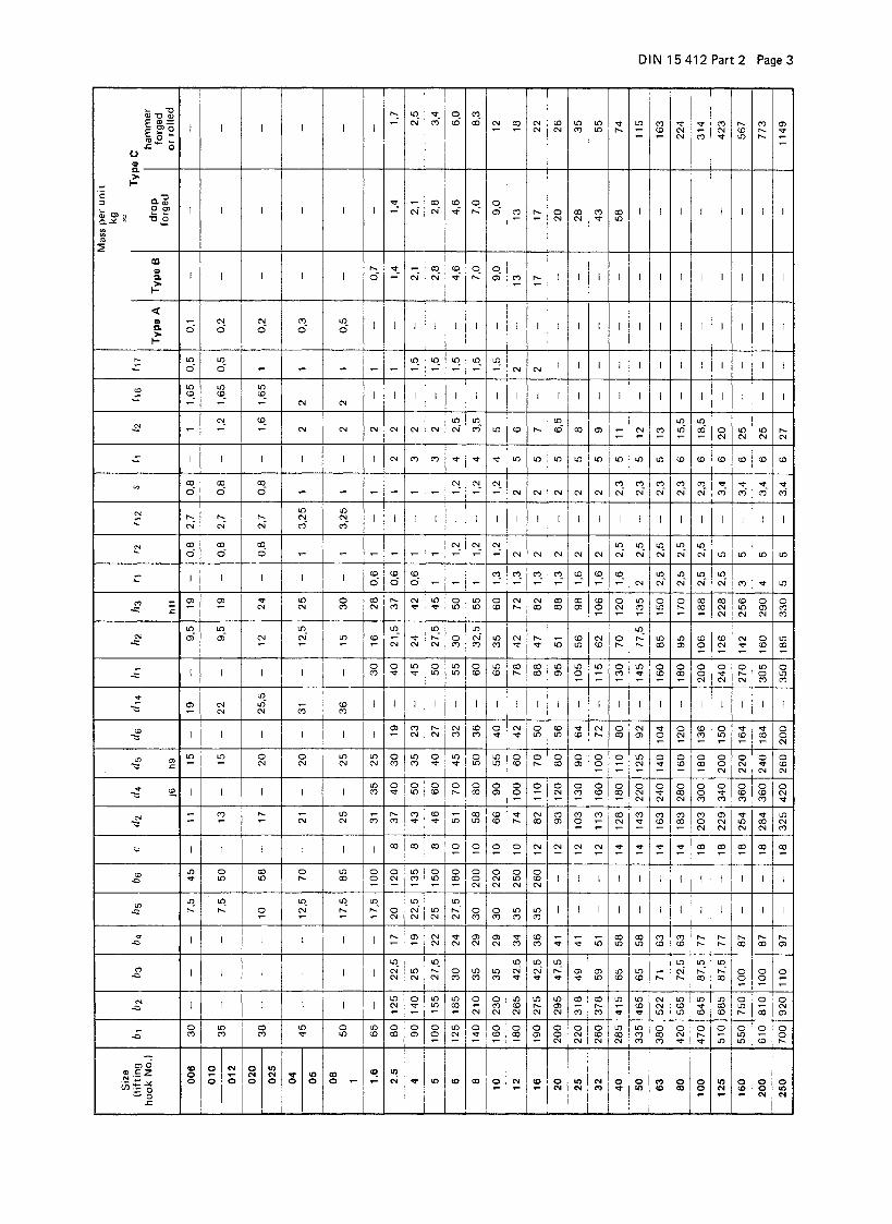
T yp e S ize ( lif tin g h ook N o.) a 4 b 1 b 2
d 1 5
d 1 6
d 17 d 18 h 1 h 2 h 4 r 19 r 20 M as s p er un it kg ~
0 06 1 6 3 0 4 5 9 - 7 17 19 9 ,5 - 4 1 ,6 0,1
0 10 a nd 0 12 1 8 3 5 5 0 11 - 9 17 19 9 ,5 - 4 1 ,6 0 ,2
0 20 a nd 0 25 2 0 3 8 5 8 14 - 13 22 24 1 2 - 5 1 ,6 0,3
04 a nd 0 5 2 3 4 5 7 0 18 - 14 22 25 12,5 - 5 1 ,6 0,4
0 8 an d 1 2 6 5 0 8 5 22 - 18 28 30 1 5 - 5 2 0,6
1 ,6 3 2 6 5 10 0 27 - 22 28 30 1 6 - 5 2 0,9
2 ,5 3 8 8 0 12 5 32 - 27 33 40 21,5 - 6 2 1,6
4 4 4 9 0 14 0 38 - 33 38 45 2 4 - 6 2 2,4
5 5 2 100 15 5 40 66 34 45 50 27,5 4 7 6 3 3,5
6 6 2 125 18 5 45 76 38 50 55 3 0 5 2 6 3 5,5
8 7 3 140 21 0 52 86 44 55 60 32,5 5 7 8 3 8,0
10 8 3 160 23 0 60 96 52 60 65 3 5 6 2 8 3 11
12 9 0 180 26 5 68 10 6 58 66 78 4 2 7 5 8 4 15
16 9 5 190 27 5 75 11 6 64 76 88 4 7 8 5 1 0 4 19
20 1 02 200 29 5 85 12 8 72 88 95 5 1 9 2 1 0 4 24
25 1 12 220 31 8 95 13 8 80 98 1 05 5 6 102 1 2 4 32
32 1 30 260 37 8 10 5 17 0 90 1 08 1 15 6 2 110 1 6 6 48
R S
40 1 45 285 41 5 11 8 19 0 1 02 1 20 1 30 7 0 125 2 0 6 65
R F 2,5 to 2 5 0 D im ensions in ac c o rdanc e w i th the app rop ria te s izes o f fin ished pa rts fo r type C c ros s piec es in ac co rdanc e w ith D IN 15 412 P a rt 2 , tak ing in to acc oun t the pe rm itted devia tions and m ach ining to le ranc es to b e ag reed .
2 Dimensions, designationType RSDrop forged (S) unmachined part (R)Type RFHammer forged or rolled (F) unmachined part (R) Type RS is illustrated
Radii without dimensions = r 20, chamfers without dimensions = 6° Designation of a type RS cross piece, size 10, assigned to class P:
Cross piece DIN 15412 - RS 10 - P
Page 2, acc. DIN 15 412 Part 1
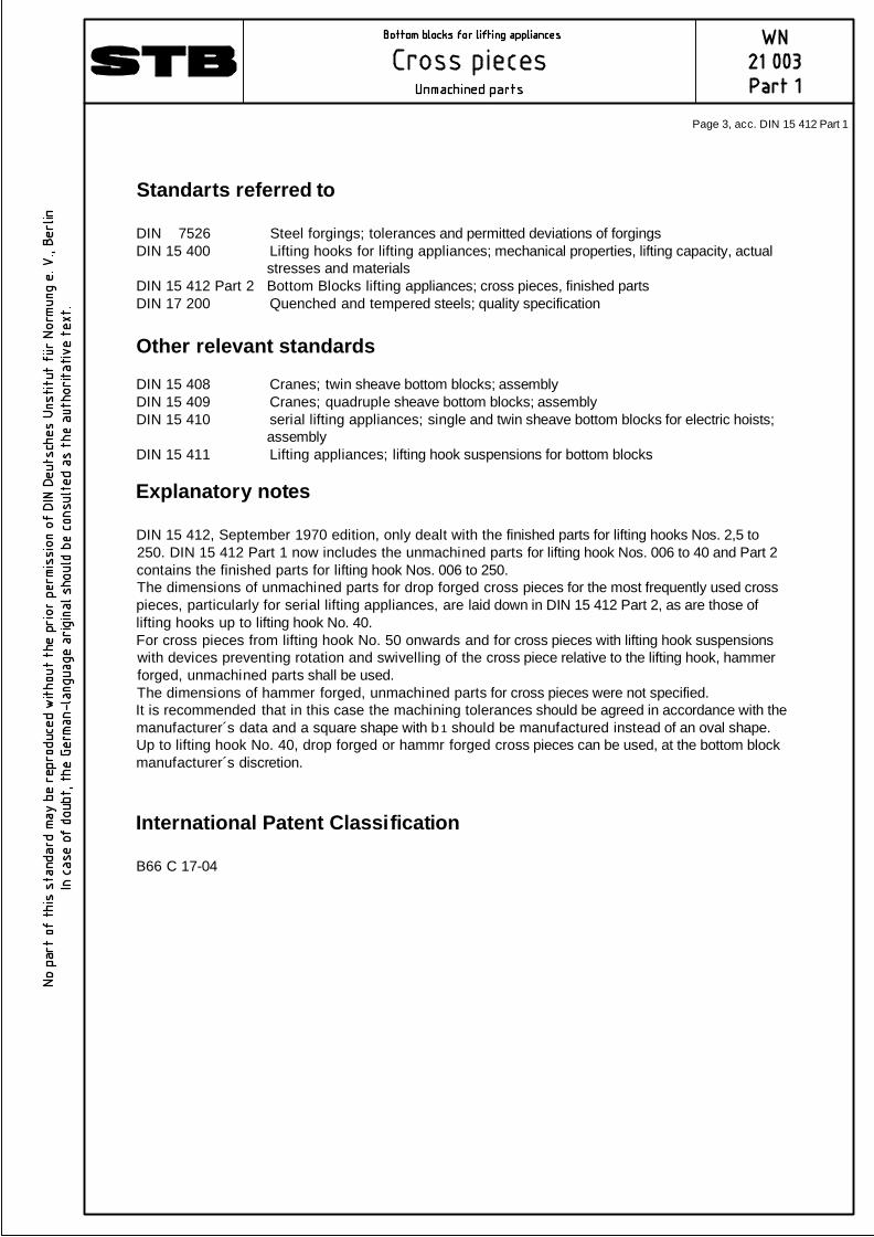
Standarts referred to
DIN 7526 Steel forgings; tolerances and permitted deviations of forgingsDIN 15 400 Lifting hooks for lifting appliances; mechanical properties, lifting capacity, actual stresses and materialsDIN 15 412 Part 2 Bottom Blocks lifting appliances; cross pieces, finished partsDIN 17 200 Quenched and tempered steels; quality specification
Other relevant standards
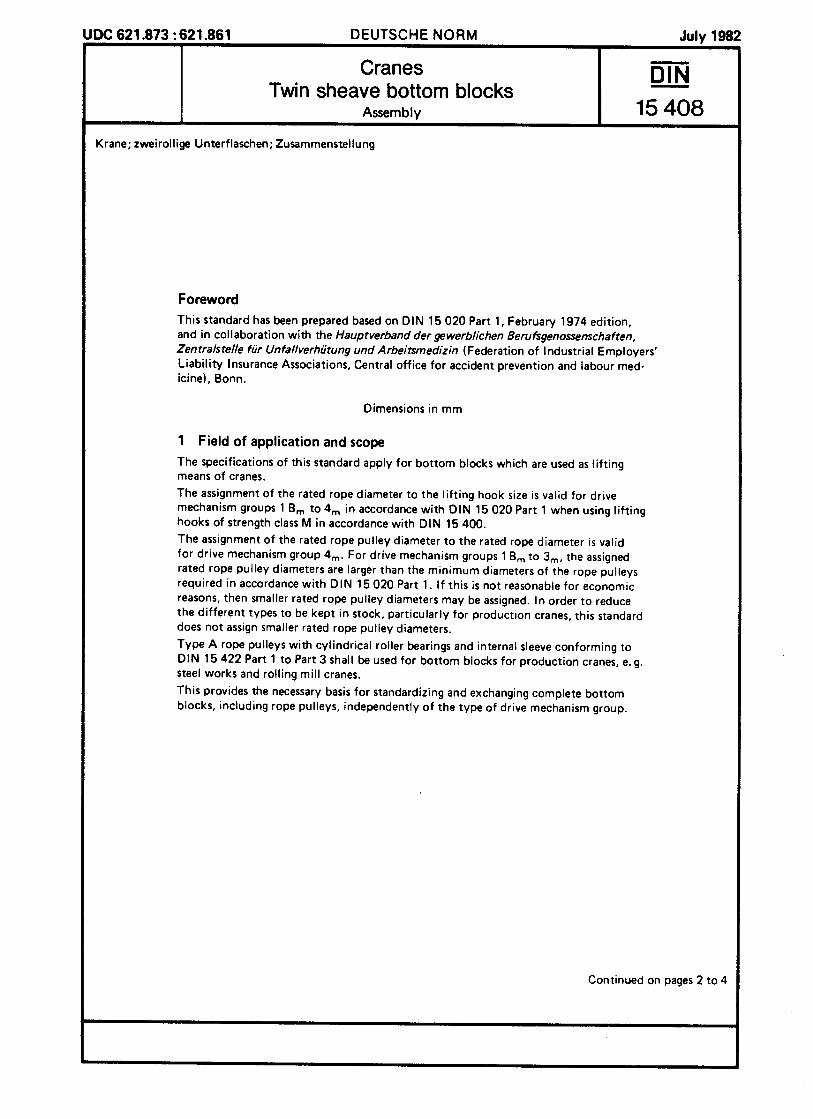
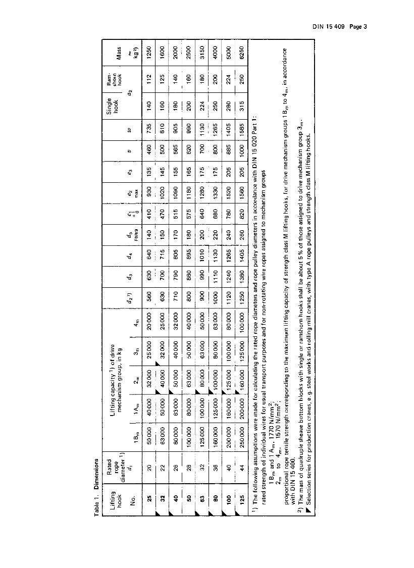
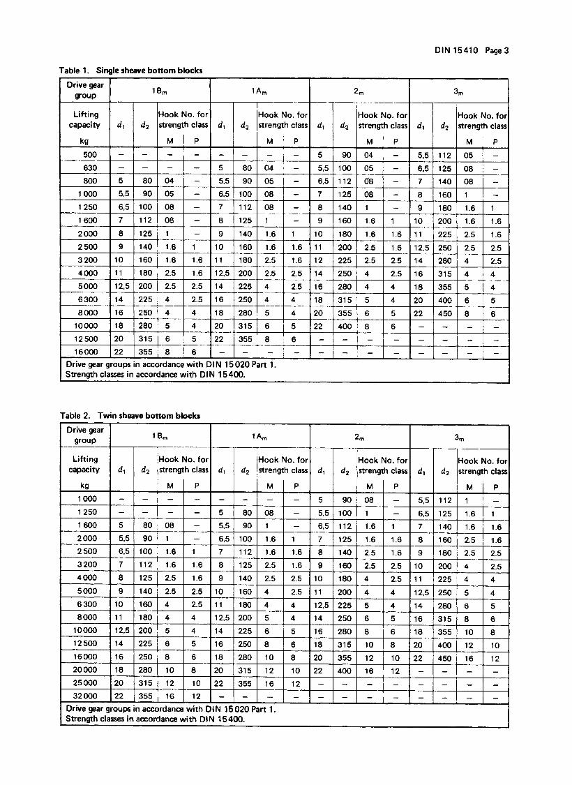
DIN 15 408 Cranes; twin sheave bottom blocks; assemblyDIN 15 409 Cranes; quadruple sheave bottom blocks; assemblyDIN 15 410 serial lifting appliances; single and twin sheave bottom blocks for electric hoists; assemblyDIN 15 411 Lifting appliances; lifting hook suspensions for bottom blocks
Explanatory notes
DIN 15 412, September 1970 edition, only dealt with the finished parts for lifting hooks Nos. 2,5 to250. DIN 15 412 Part 1 now includes the unmachined parts for lifting hook Nos. 006 to 40 and Part 2contains the finished parts for lifting hook Nos. 006 to 250.The dimensions of unmachined parts for drop forged cross pieces for the most frequently used crosspieces, particularly for serial lifting appliances, are laid down in DIN 15 412 Part 2, as are those oflifting hooks up to lifting hook No. 40.For cross pieces from lifting hook No. 50 onwards and for cross pieces with lifting hook suspensionswith devices preventing rotation and swivelling of the cross piece relative to the lifting hook, hammerforged, unmachined parts shall be used.The dimensions of hammer forged, unmachined parts for cross pieces were not specified.It is recommended that in this case the machining tolerances should be agreed in accordance with themanufacturer´s data and a square shape with b 1 should be manufactured instead of an oval shape.Up to lifting hook No. 40, drop forged or hammr forged cross pieces can be used, at the bottom blockmanufacturer´s discretion.
International Patent Classification
B66 C 17-04
Page 3, acc. DIN 15 412 Part 1
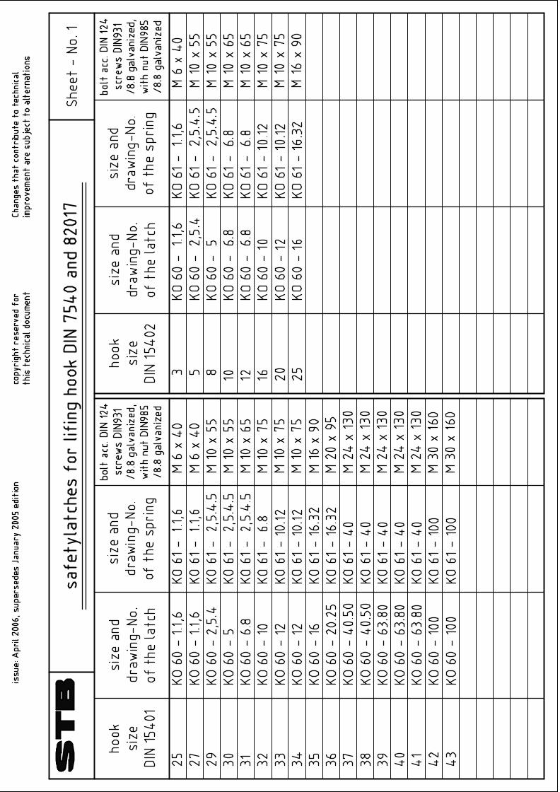
Hook safety latches According UVV VBG 9 a § 19 principally load hooks have to be designed in a way that an unintended loss of the load suspension devices, the lifting means or the load can be avoided. This requirement is fulfilled if e.g. safety latches are existing. Safety latches are normally mounted to the load hook with a nose. According to UVV hooks with a shank can be designed with a clamp. Welding of nose is forbidden. Hook safety latches according DIN 15106 are to be used for drop forged single hook Form GSN and GFN according DIN 15401/2 to avoid an unintended loss of the lifting means. DIN 15106 indicates that equivalent hook safety latches which are produced with a different manufacturing technology or in reinforced design for productions cranes are acceptable if the protection intention according to Chapter 2 is achieved. To meet the requirement of UVV in consideration of DIN 15106 we have designed hook safety latches which can be used for single hooks acc. DIN 15401 size no.1 to no.250, for double hooks acc. DIN 15402 size no. 2,5 to no.250, for eye hooks acc. DIN 7540 size no. 27 to no.36 and WN size no. 37 to no.42, for cargo hooks acc. DIN 82017 size no. 3 to no.16 and for cross hooks acc. WN 21061 capacity 2,5 to 10 tons. The advantage of this design consists of facts that also double hooks which have 2 mouthpieces and therefore a double risk of an unintended loss of the lifting means are covered, the latches are made out of solid steel plate, the spring is produced out of stainless steel material and a easy serviceable screw joint is used which especially for hook with a high load capacity guarantees a quick and risk less assembly. Acc. UVV ZH 1/27 functional capability of hook safety latches has to be checked regularly. Hook safety latches for load suspension devices which are intended for passenger transport are subject to rigorous obligations. They have to close and lock autonomously without spring movement. Additionally the lock mechanism has to be protected with a screw connection which is fixed with a splint. If you need these hook safety latches please ask for a quote stating the hook size.
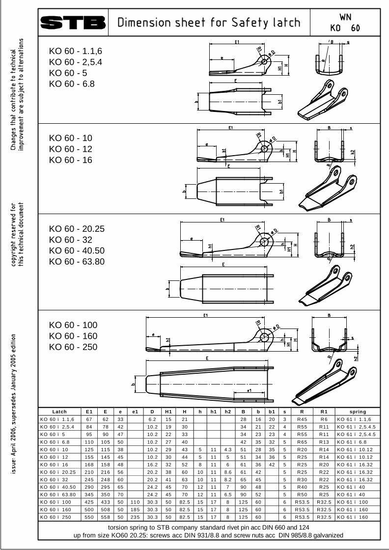
Latch E1 E e e1 D H1 H h h1 h2 B b b1 s R R1 spring KO 60 – 1.1,6 67 62 33 6.2 15 21 28 16 20 3 R45 R6 KO 61 – 1.1,6 KO 60 – 2,5.4 84 78 42 10.2 19 30 34 21 22 4 R55 R11 KO 61 – 2,5.4.5 KO 60 – 5 95 90 47 10.2 22 33 34 23 23 4 R55 R11 KO 61 – 2,5.4.5 KO 60 – 6.8 110 105 50 10.2 27 40 42 35 32 5 R65 R13 KO 61 – 6.8 KO 60 – 10 125 115 38 10.2 29 43 5 11 4.3 51 28 35 5 R20 R14 KO 61 – 10.12 KO 60 – 12 155 145 45 10.2 30 44 5 11 5 51 34 36 5 R25 R14 KO 61 – 10.12 KO 60 – 16 168 158 48 16.2 32 52 8 11 6 61 36 42 5 R25 R20 KO 61 – 16.32 KO 60 – 20.25 210 216 56 20.2 38 60 10 11 8.6 61 42 5 R25 R22 KO 61 – 16.32 KO 60 – 32 245 248 60 20.2 41 63 10 11 8.2 65 45 5 R30 R22 KO 61 – 16.32 KO 60 – 40.50 290 295 65 24.2 45 70 12 11 7 90 48 5 R40 R25 KO 61 – 40 KO 60 – 63.80 345 350 70 24.2 45 70 12 11 6.5 90 52 5 R50 R25 KO 61 – 40 KO 60 – 100 425 433 50 110 30.3 50 82.5 15 17 8 125 60 6 R53.5 R32.5 KO 61 – 100 KO 60 – 160 500 508 50 185 30.3 50 82.5 15 17 8 125 60 6 R53.5 R32.5 KO 61 – 160 KO 60 – 250 550 558 50 235 30.3 50 82.5 15 17 8 125 60 6 R53.5 R32.5 KO 61 – 160
torsion spring to STB company standard rivet pin acc DIN 660 and 124up from size KO60 20.25: screws acc DIN 931/8.8 and screw nuts acc DIN 985/8.8 galvanized
KO 60 - 20.25KO 60 - 32KO 60 - 40.50KO 60 - 63.80
KO 60 - 100KO 60 - 160KO 60 - 250
KO 60 - 10KO 60 - 12KO 60 - 16
KO 60 - 1.1,6KO 60 - 2,5.4KO 60 - 5KO 60 - 6.8
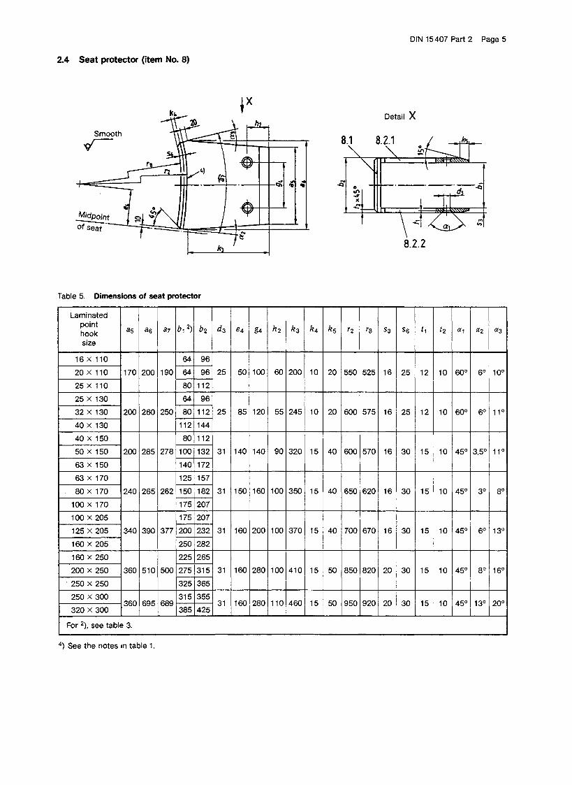
d i m e n s i o n s ( m m ) L o a d c a p a c i t y
[ t o ]
l a m i n a t e d h o o k s
a 1 1 ) a 2 b 1 b 2 d 1 1 ) g 1 l 1 1 ) l 2 s 1
n u m b e r o f p i e c e s f o r
i t e m 1
l o a d c a p a c i t y o f r e l a t e d
l a d l e c r a n c e s [ t o ]
1 6 1 3 0 6 4 9 6 2 3 2 2 0 1 4 5 6 4 9 6 2 4 0
2 5
1 1 0
1 6 0 8 0 1 1 2
1 0 0 2 2 0 1 0 0 0 1 7 0 1 6
3 5 0 2 5 1 6 0 6 4 9 6 2 5 0 3 2 1 8 0 8 0 1 1 2 3 6 3
4 0
1 3 0
2 0 0 1 1 2 1 4 4
1 2 5 2 8 0 1 1 2 0 2 0 0 1 6
5 8 0 4 0 2 0 0 8 0 1 1 2 2 8 0 5 0 2 2 5 1 0 0 1 3 2 3 1 0 0 6 3
1 5 0
2 2 5 1 4 0 1 7 2
1 6 0 3 4 0 1 2 5 0 2 5 0 2 0
5 1 2 5 6 3 2 2 5 1 2 5 1 5 7 3 1 2 5 8 0 2 5 0 1 5 0 1 8 2 4 1 6 0
1 0 0
1 7 0
2 5 0 1 7 5 2 0 7
1 8 0 3 8 0 1 4 0 0 3 0 0 2 5
5 2 0 0 1 0 0 2 5 0 1 7 5 2 0 7 5 2 0 0
1 2 5 2 8 0 2 0 0 2 3 2 6 2 5 0 1 6 0
2 0 5
3 2 0 2 5 0 2 8 2
2 2 5 4 6 0 1 6 0 0 3 5 0 2 5
8 3 2 0 1 6 0 3 2 0 2 2 5 2 6 5 7 3 2 0
2 0 0 3 6 0 2 7 5 3 1 5 9 4 0 0 2 5 0
2 5 0
4 0 0 3 2 5 3 6 5
2 5 0 5 5 0 1 8 0 0 4 2 0 2 5
1 1 5 0 0 2 5 0 4 0 0 3 1 5 3 5 5 7 5 0 0
3 2 0 3 0 0
5 0 0 3 8 5 4 2 5 2 9 0 6 2 0 2 0 0 0 4 7 0 3 5
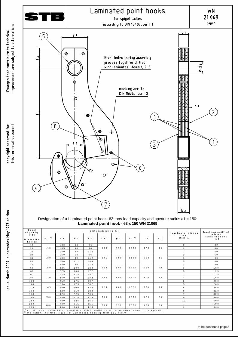
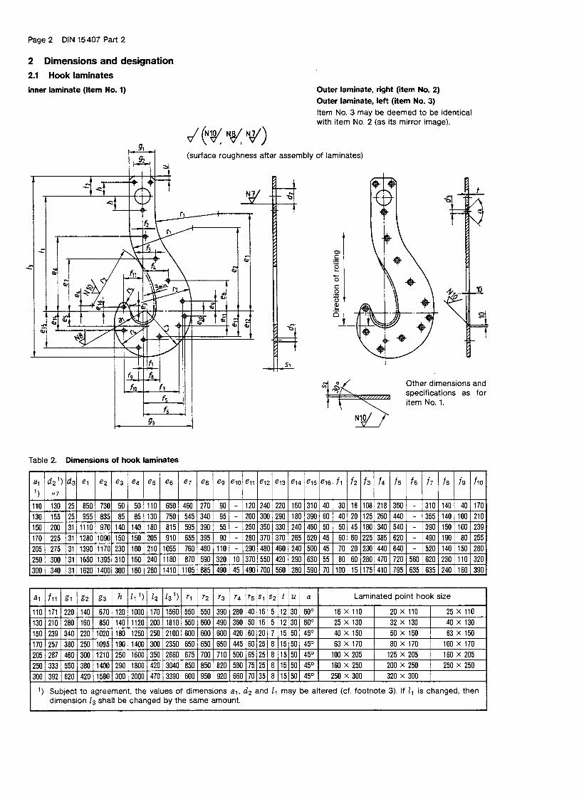
9 6 3 0 1 ) a 1 , d 1 a n d l 1 c a n b e a d j u s t e d t o s p e c i a l c o n d i t i o n s . D i f f e r i n g d i m e n s i o n s t o b e a g r e e d .
2 ) I n d ic a t i o n : t h i s r i v e t i s j u s t f o r L a m i n a t e d h o o k u p f r o m 1 6 0 x 2 5 0
Designation of a Laminated point hook, 63 tons load capacity and aperture radius a1 = 150:Laminated point hook - 63 x 150 WN 21069
to be continued page 2
n u m b e r o f p ie c e s f o r l a m in a t e d h o o k s e r i a l
n u m b e r 1 6 x 1 1 0 u p t o
4 0 x 1 3 0
4 0 x 1 5 0 u p t o
1 6 0 x 2 0 5
1 6 0 x 2 5 0 u p t o
3 2 0 x 3 0 0
d e s ig n a t i o n o r
s t a n d a r d d e s ig n a t i o n m a t e r i a l
1 1 1 0 1 3 0 6 4 in n e r l a m in a t e 2 1 1 1 o u t e r l a m in a t e , r ig h t 3 1 1 1 o u t e r l a m in a t e , le f t 4 1 1 1 h o o k s e a t 5 1 1 1 e y e h o le
a c c . t o D IN 1 5 4 0 7 , p a r t 2
1 2 - - c o u n t e r - h e a d r i v e t D IN 3 0 2 – 2 4 x … 6 1 )
- 1 2 1 3 c o u n t e r - h e a d r i v e t D IN 3 0 2 – 3 0 x … 3 - - c o u n t e r - h e a d r i v e t D IN 3 0 2 – 2 4 x …
7 1 ) - 3 3 c o u n t e r - h e a d r i v e t D IN 3 0 2 – 3 0 x …
S t 3 4 a c c . t o D IN 1 7 1 1 0
8 1 1 1 s e a t p r o t e c t o r a c c . t o D IN 1 5 4 0 7 , p a r t 2 1 ) l e n g t h o f c o u n t e r - h e a d r iv e ts ( s e r i a l n u m b e r s 6 a n d 7 ) t o a g r e e d w i t h o r d e r
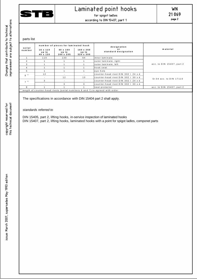
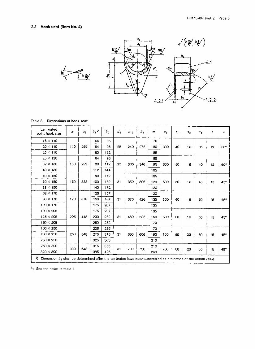
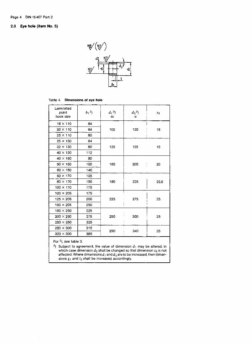
The specifications in accordance with DIN 15404 part 2 shall apply.
parts list
standards referred to
DIN 15405, part 2, lifting hooks, in-service inspection of laminated hooksDIN 15407, part 2, lifting hooks, laminated hooks with a point for spigot ladles, componet parts
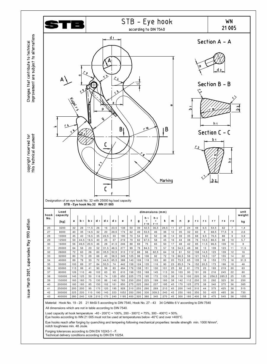
dim ensions (m m) hook No.
Load capacity
[kg] a b 1 b 2 d 1 d 2 d 3 e f g
h 1 =
r 10
h 2 =
r 11 k m n p r 3 r 5 r 7 r 8 r 9
unit weight
kg
25 3200 32 28 11,5 26 16 23,5 138 50 39 42,5 36,5 28,5 11 27 24 48 6,5 54,5 62 7 1,4
27 8000 40 35 14,5 32 20 29,5 174 62 49 53,5 46 36 12 35 32 60 8 68,5 77,5 9 2,6
28 10000 45 40 16,5 35 22,5 33 190 70 54 60 52 36 14 39 35 68 9,5 76,5 86 9 3,9
29 12500 50 44,5 18,5 40 25 37 219 79 62 67,5 58 45 16 44 38 76 10,5 86,5 98 10 5,7
30 16000 56 49,5 20,5 46 28 41,5 246 88 69 75 65 50 17 48 42 85 11,5 96,5 109 10 8
31 20000 64 56 23 52 31,5 46,5 277 99 78 84,5 73 57 18 54,5 48 96 13 109 123 11 11,5
32 28000 72 63 26 60 35,5 52,5 313 112 88 96 82,5 64 18 61 52 108 14,5 123 139 12 16
33 32000 80 70 29 66 40 58,5 349 125 98 106 92 72 19 66,5 58 121 16,5 137 155 14 22
34 40000 89 78 33 72 44,5 65,5 388 140 109 118 103 80 20 73,5 65 135 18 153 173 16 31,5
35 50000 100 89 37 84 50,5 74 442 158 124 135 116 90 23 85,5 74 152 20,5 173 196 18 46
36 63000 113 99 41 90 56 83 494 176 138 151 130 101 25 92 81 170 23 193 219 20 63
37 80000 126 110 46 102 63 93 610 198 155 168 145 113 30 103 90 191 26 216 245 22 80
38 100000 140 125 50 116 74 120 650 225 175 195 172 133 38 118 100 220 30 256,5 285,5 25 125
39 150000 160 160 75 130 86 140 765 250 200 225 199 160 38 142 112 250 33 292 325 30 250
40 200000 180 180 85 150 102 161 850 275 225 260 237 195 45 170 125 275 38 340 375 36 365
41 250000 200 200 95 170 120 195 928 310 255 290 269 210 45 200 140 310 44 375 425 38 515
42 300000 225 220 110 190 140 223 1052 350 290 330 309,5 240 45 250 160 350 50 425 485 38 730
43 400000 280 240 128 210 170 240 1195 400 320 380 345 270 45 300 180 400 58 475 545 38 1055
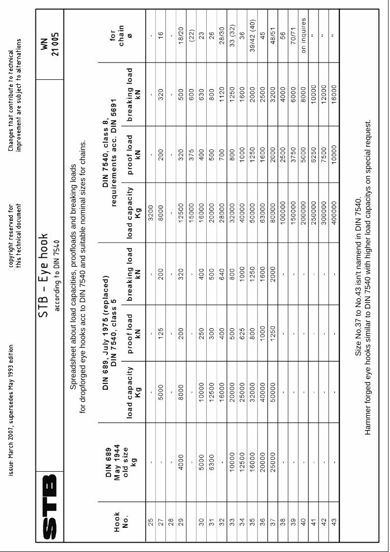
Spr
eads
heet
abo
ut lo
ad c
apac
ities
, pro
oflo
ads
and
brea
king
load
sfo
r dro
pfor
ged
eye
hook
s ac
c to
DIN
754
0 an
d su
itabl
e no
min
al s
izes
for c
hain
s.
Siz
e N
o.37
to N
o.43
isn'
t nam
end
in D
IN 7
540.
Ham
mer
forg
ed e
ye h
ooks
sim
ilar t
o D
IN 7
540
with
hig
her l
oad
capa
city
s on
spe
cial
requ
est.
Note for special hook suspensions with electrical isolation acc STB Form 1777 The Isolation is designed in a way that mechanical damage during operation can not occur. An unintended removal of the isolation is not possible. The design of the isolation makes sure that electrical current can not affect the roller baring. Using fabric-base laminate materials HGW 2082 absorption of moisture is avoided which can occur by using polyamides. Enough space between nut and crosshead has to be considered. To avoid electrical conductivity of the roller baring lubricant only lithium-saponifieded EP-fat should be used (ARAL Longlife Fat H or Klüberplex Be 31-502). According to the lubricant supplier the electrical conductivity is near 0. An additional isolating effect can not demonstrated. Annex table DIN 7735 Hamm, 01.April.2007
Stahlhammer Bommern GmbH
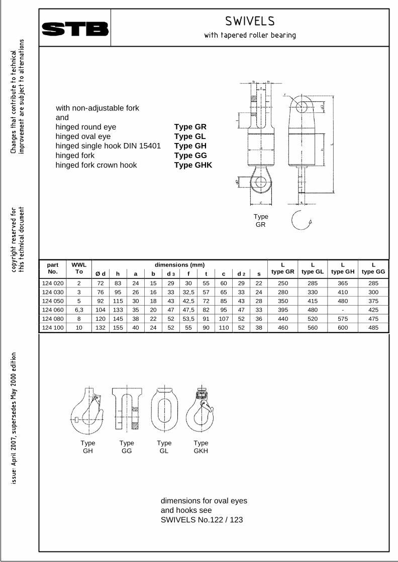
dimensions (mm) part No.
WWL To Ø d h a b d 3 f t c d 2 s
L type GR
L type GL
L type GH
L type GG
124 020 2 72 83 24 15 29 30 55 60 29 22 250 285 365 285 124 030 3 76 95 26 16 33 32,5 57 65 33 24 280 330 410 300 124 050 5 92 115 30 18 43 42,5 72 85 43 28 350 415 480 375 124 060 6,3 104 133 35 20 47 47,5 82 95 47 33 395 480 - 425 124 080 8 120 145 38 22 52 53,5 91 107 52 36 440 520 575 475 124 100 10 132 155 40 24 52 55 90 110 52 38 460 560 600 485
with non-adjustable forkandhinged round eyehinged oval eyehinged single hook DIN 15401hinged forkhinged fork crown hook
Type GRType GLType GHType GGType GHK
TypeGH
TypeGG
TypeGL
TypeGKH
dimensions for oval eyesand hooks seeSWIVELS No.122 / 123
TypeGR
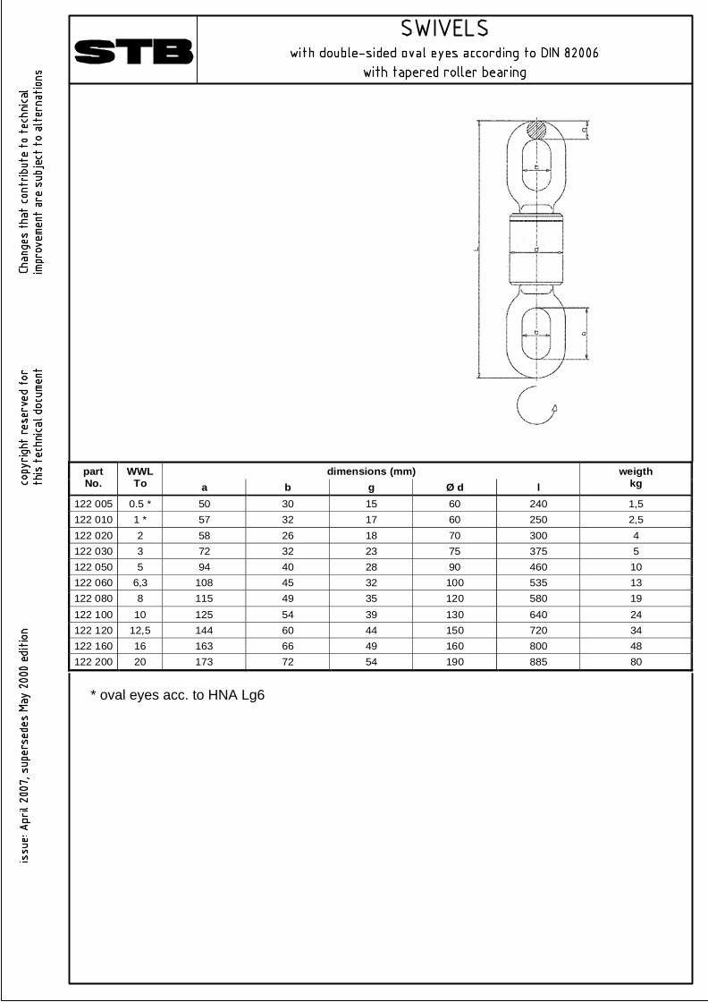
dimensions (mm) part No.
WWL To a b g Ø d l
weigth kg
122 005 0.5 * 50 30 15 60 240 1,5 122 010 1 * 57 32 17 60 250 2,5 122 020 2 58 26 18 70 300 4 122 030 3 72 32 23 75 375 5 122 050 5 94 40 28 90 460 10 122 060 6,3 108 45 32 100 535 13 122 080 8 115 49 35 120 580 19 122 100 10 125 54 39 130 640 24 122 120 12,5 144 60 44 150 720 34 122 160 16 163 66 49 160 800 48 122 200 20 173 72 54 190 885 80
* oval eyes acc. to HNA Lg6
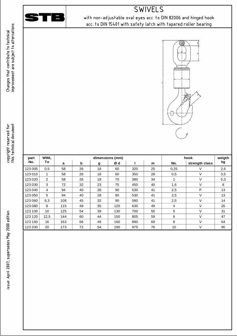
dimensions (mm) hook part No.
WWL To a b g Ø d l m No. strength class
weigth kg
123 005 0.5 58 26 18 60 320 25 0,25 V 2,6 123 010 1 58 26 18 60 350 28 0,5 V 3,5 123 020 2 58 26 18 70 380 34 1 V 5,3 123 030 3 72 32 23 75 450 40 1,6 V 8 123 040 4 94 40 28 90 530 41 2,5 P 13 123 050 5 94 40 28 90 530 41 2,5 V 13 123 060 6,3 108 45 32 90 580 41 2,5 V 14 123 080 8 115 49 35 120 630 49 4 V 26 123 100 10 125 54 39 130 700 55 5 V 31 123 120 12,5 144 60 44 150 805 59 6 V 47 123 160 16 163 66 49 160 890 69 8 V 64 123 200 20 173 72 54 190 975 76 10 V 90
C orrespo nd in g p iece p ar ts (b y o n es )
Item 1 item 2 item 3 bo w D IN
8201 8-
O val eye DIN
82 006 -
n ut D IN
82 013
No m in al siz e
Perm iss ib le stre ss
kN
a 1 a 2 b 1 b 2 d 1 g 2 l v
W e ig ht / u n it kg
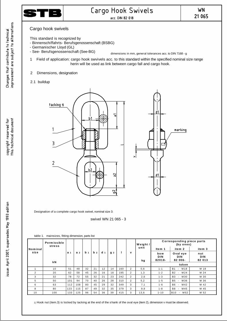
tok en 1 10 51 48 32 21 12 14 160 2 0 ,6 1-1 B1 - M 18 M 18 2 20 62 58 45 26 16 18 195 2 1 ,3 1-2 B2 - M 24 M 24 3 32 78 72 55 32 21 23 242 2 2 ,6 1-3 B3 - M 30 M 30 5 50 101 94 70 40 26 28 310 2 5 ,2 1 -5 B5 - M 36 M 36 6 63 112 108 80 45 29 32 349 3 7 ,1 1 -6 B6 - M 42 M 42 8 80 123 115 87 49 32 35 379 3 9 ,9 1-8 B8 - M 45 M 45
10 100 133 125 96 54 36 39 415 3 13 ,6 1-10 B10 - M 52 M 52
dimensions in mm, general tolerances acc. to DIN 7168 - g
Cargo hook swivels
This standard is recognized by- Binnenschiffahrts- Berufsgenossenschaft (BSBG)- Germanischer Lloyd (GL)- See- Berufsgenossenschaft (See-BG)
1 Field of application: cargo hook swvivels acc. to this standard within the specified nominal size range herin will be used as link between cargo fall and cargo hook.
2 Dimensions, designation
2.1 buildup
1) Hook nut (item.3) is locked by tacking at the end of the shank of the oval eye (item 2), dimension v must be observed.
Designation of a complete cargo hook swivel, nominal size 3:
swivel WN 21 065 - 3
table 1. mainsizes, fitting dimension, parts list
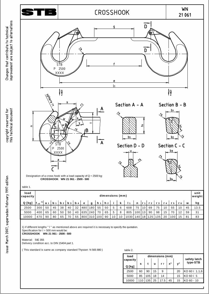
dim ensions (mm) load
capacity
Q [kg] f ± 5 1 ) a 1 b 1 b 2 b 3 b 4 e g h 1 h 2 i k l 1 n r 1 r 2 r 3 r 4 r 5 r 6 w
unit weight
kg
2500 300 50 45 38 40 32 480 180 55 50 5 6 608 75 10 69 75 10 55 10 45 13.5 5000 400 65 60 50 50 40 635 240 70 65 5 8 805 100 13 90 98 15 70 12 59 31
10000 470 90 80 65 70 55 800 310 100 90 10 10 1030 140 18 125 135 20 100 15 81 83
1) if different lengths " l " as mentioned above are required it is necessary to specify the quotation.Specification for l = 500 mm would be:CROSSHOOK WN 21 061 - 2500 - 500
Designation of a cross hook with a load capacity of Q = 2500 kg:CROSSHOOK WN 21 061 - 2500 - 500
Material: StE 355Delivery condition acc. to DIN 15404 part 1.
( This standard is same as company standard Thyssen N 565 880 )
STBP 2500XXXX
STBP 2500XXXX
table 1.
dimensions (mm) load capacity
Q [kg]
s t u r 7 x° y° safety latch
type-STB
2500 60 90 15 9 20 KO 60 – 1.1,6 5000 85 105 18 14 15 KO 60 – 5
10000 110 135 25 17.5 45 15 KO 60 - 10
table 2.

dim ensions (m m) load
capacity
Q [kg] a b 1 b 2 +2 d e ±0.5 h 1 h 2 +2 r min.
unit weight
kg
2500 70 155 45 18 115 65 55 18 1,8 5000 80 190 60 22 140 80 70 22 2,8
10000 90 230 80 26 170 110 100 26 4,6
Designation of a holder for cross hook with a load capacity of Q = 2500 kg:HOLDER FOR CROSSHOOK WN 21 061 - H - 2500
Material: RPSt 37 - 2 or PSt 37 - 3acc. to DIN 17100 or to manufacurer´s discretion,Delivery condition acc. to DIN 15404 part 1.
( This standard is same as company standard Thyssen N 565 882 )
Not specified details must beselect to serve the purpose.
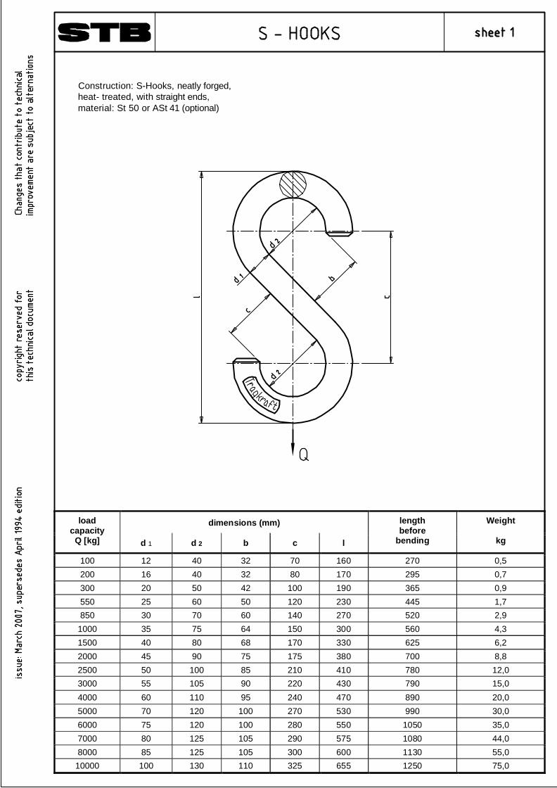
dimensions (mm) load capacity
Q [kg] d 1 d 2 b c l
length before
bending
Weight
kg
100 12 40 32 70 160 270 0,5 200 16 40 32 80 170 295 0,7 300 20 50 42 100 190 365 0,9 550 25 60 50 120 230 445 1,7 850 30 70 60 140 270 520 2,9
1000 35 75 64 150 300 560 4,3 1500 40 80 68 170 330 625 6,2 2000 45 90 75 175 380 700 8,8 2500 50 100 85 210 410 780 12,0 3000 55 105 90 220 430 790 15,0 4000 60 110 95 240 470 890 20,0 5000 70 120 100 270 530 990 30,0 6000 75 120 100 280 550 1050 35,0 7000 80 125 105 290 575 1080 44,0 8000 85 125 105 300 600 1130 55,0
10000 100 130 110 325 655 1250 75,0
Construction: S-Hooks, neatly forged,heat- treated, with straight ends,material: St 50 or ASt 41 (optional)
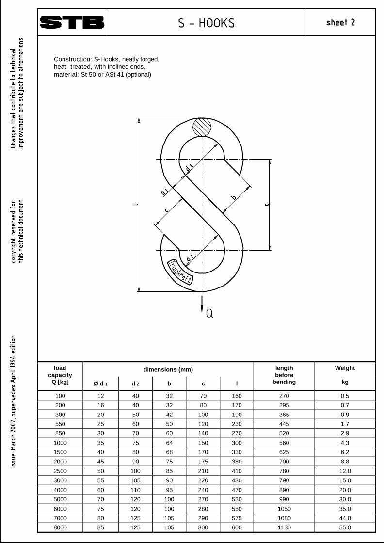
dimensions (mm) load capacity
Q [kg] Ø d 1 d 2 b c l
length before
bending
Weight
kg
100 12 40 32 70 160 270 0,5 200 16 40 32 80 170 295 0,7 300 20 50 42 100 190 365 0,9 550 25 60 50 120 230 445 1,7 850 30 70 60 140 270 520 2,9
1000 35 75 64 150 300 560 4,3 1500 40 80 68 170 330 625 6,2 2000 45 90 75 175 380 700 8,8 2500 50 100 85 210 410 780 12,0 3000 55 105 90 220 430 790 15,0 4000 60 110 95 240 470 890 20,0 5000 70 120 100 270 530 990 30,0 6000 75 120 100 280 550 1050 35,0 7000 80 125 105 290 575 1080 44,0 8000 85 125 105 300 600 1130 55,0
Construction: S-Hooks, neatly forged,heat- treated, with inclined ends,material: St 50 or ASt 41 (optional)
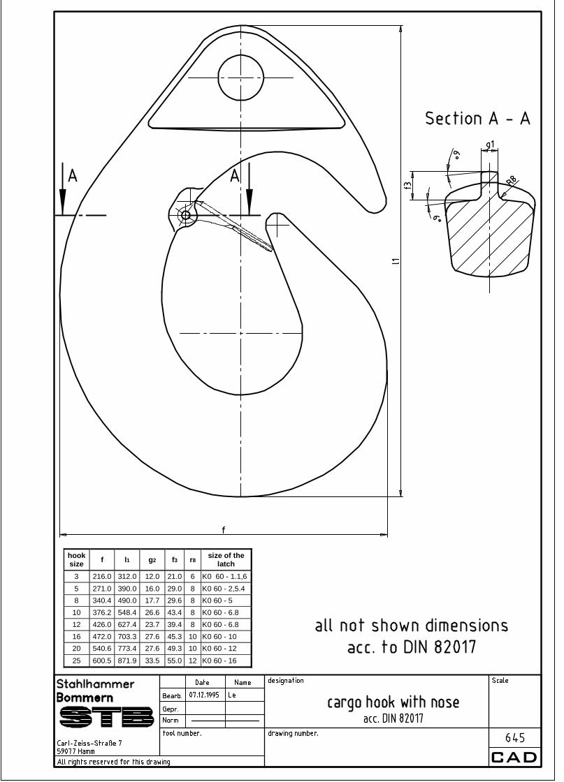
hoo k size
1)
ad m is sib le lo ad kN
b 1 b 2 b 3 d e f h 1 h 2 l 1 p r 1 r 3 s 1 s 2 s 3 s 4 s5 typ e A B
w e igh t u n it
kg
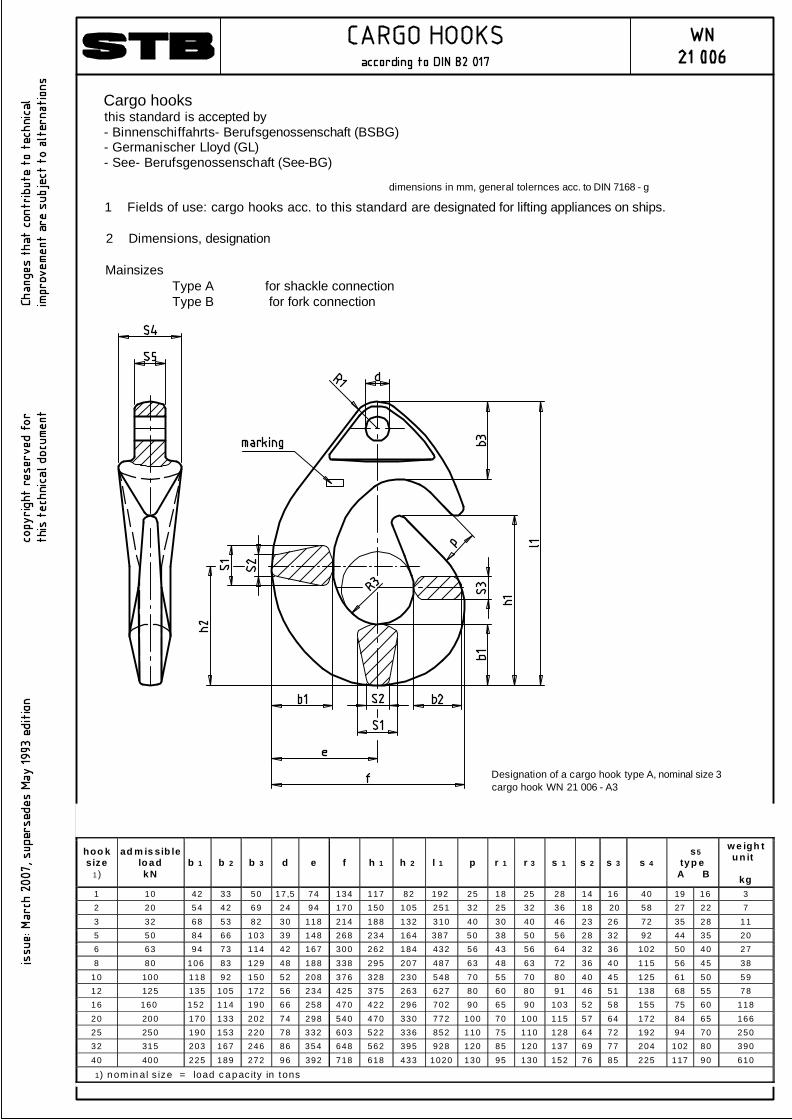
1 10 42 33 50 17 ,5 74 134 117 82 192 25 18 25 28 14 16 40 19 16 3 2 20 54 42 69 24 94 170 150 105 251 32 25 32 36 18 20 58 27 22 7 3 32 68 53 82 30 118 214 188 132 310 40 30 40 46 23 26 72 35 28 11 5 50 84 66 103 39 148 268 234 164 387 50 38 50 56 28 32 92 44 35 20 6 63 94 73 114 42 167 300 262 184 432 56 43 56 64 32 36 102 50 40 27 8 80 106 83 129 48 188 338 295 207 487 63 48 63 72 36 40 115 56 45 38
10 100 118 92 150 52 208 376 328 230 548 70 55 70 80 40 45 125 61 50 59 12 125 135 105 172 56 234 425 375 263 627 80 60 80 91 46 51 138 68 55 78 16 160 152 114 190 66 258 470 422 296 702 90 65 90 103 52 58 155 75 60 118 20 200 170 133 202 74 298 540 470 330 772 100 70 100 115 57 64 172 84 65 166 25 250 190 153 220 78 332 603 522 336 852 110 75 110 128 64 72 192 94 70 250 32 315 203 167 246 86 354 648 562 395 928 120 85 120 137 69 77 204 102 80 390 40 400 225 189 272 96 392 718 618 433 1020 130 95 130 152 76 85 225 117 90 610
1) nom in al s ize = load c apac ity in tons
dimensions in mm, general tolernces acc. to DIN 7168 - g
Designation of a cargo hook type A, nominal size 3cargo hook WN 21 006 - A3
Cargo hooksthis standard is accepted by- Binnenschiffahrts- Berufsgenossenschaft (BSBG)- Germanischer Lloyd (GL)- See- Berufsgenossenschaft (See-BG)
1 Fields of use: cargo hooks acc. to this standard are designated for lifting appliances on ships.
2 Dimensions, designation
Mainsizes Type A for shackle connection Type B for fork connection
CAD
hook size f l1 g2 f3 r8 size of the
latch 3 216.0 312.0 12.0 21.0 6 K0 60 - 1.1,6 5 271.0 390.0 16.0 29.0 8 K0 60 - 2,5.4 8 340.4 490.0 17.7 29.6 8 K0 60 - 5 10 376.2 548.4 26.6 43.4 8 K0 60 - 6.8 12 426.0 627.4 23.7 39.4 8 K0 60 - 6.8 16 472.0 703.3 27.6 45.3 10 K0 60 - 10 20 540.6 773.4 27.6 49.3 10 K0 60 - 12 25 600.5 871.9 33.5 55.0 12 K0 60 - 16
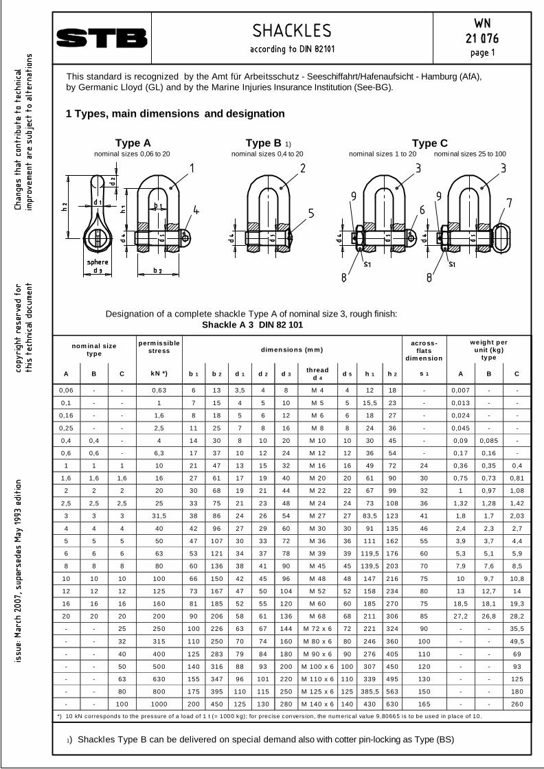
nom inal size type dimensions (m m)
weight per unit (kg)
type
A B C
perm issible stress
kN *) b 1 b 2 d 1 d 2 d 3 thread d 4 d 5 h 1 h 2
across- flats
dim ension
s 1 A B C
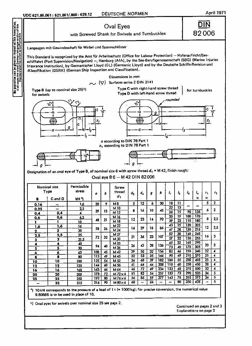
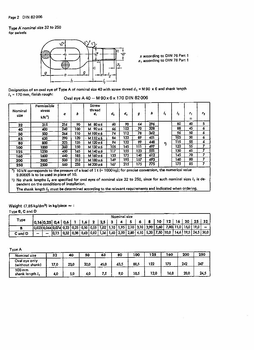
0,06 - - 0,63 6 13 3,5 4 8 M 4 4 12 18 - 0,007 - -
0,1 - - 1 7 15 4 5 10 M 5 5 15,5 23 - 0,013 - -
0,16 - - 1,6 8 18 5 6 12 M 6 6 18 27 - 0,024 - -
0,25 - - 2,5 11 25 7 8 16 M 8 8 24 36 - 0,045 - -
0,4 0,4 - 4 14 30 8 10 20 M 10 10 30 45 - 0,09 0,085 -
0,6 0,6 - 6,3 17 37 10 12 24 M 12 12 36 54 - 0,17 0,16 -
1 1 1 10 21 47 13 15 32 M 16 16 49 72 24 0,36 0,35 0,4
1,6 1,6 1,6 16 27 61 17 19 40 M 20 20 61 90 30 0,75 0,73 0,81
2 2 2 20 30 68 19 21 44 M 22 22 67 99 32 1 0,97 1,08
2,5 2,5 2,5 25 33 75 21 23 48 M 24 24 73 108 36 1,32 1,28 1,42
3 3 3 31,5 38 86 24 26 54 M 27 27 83,5 123 41 1,8 1,7 2,03
4 4 4 40 42 96 27 29 60 M 30 30 91 135 46 2,4 2,3 2,7
5 5 5 50 47 107 30 33 72 M 36 36 111 162 55 3,9 3,7 4,4
6 6 6 63 53 121 34 37 78 M 39 39 119,5 176 60 5,3 5,1 5,9
8 8 8 80 60 136 38 41 90 M 45 45 139,5 203 70 7,9 7,6 8,5
10 10 10 100 66 150 42 45 96 M 48 48 147 216 75 10 9,7 10,8
12 12 12 125 73 167 47 50 104 M 52 52 158 234 80 13 12,7 14
16 16 16 160 81 185 52 55 120 M 60 60 185 270 75 18,5 18,1 19,3
20 20 20 200 90 206 58 61 136 M 68 68 211 306 85 27,2 26,8 28,2
- - 25 250 100 226 63 67 144 M 72 x 6 72 221 324 90 - - 35,5
- - 32 315 110 250 70 74 160 M 80 x 6 80 246 360 100 - - 49,5
- - 40 400 125 283 79 84 180 M 90 x 6 90 276 405 110 - - 69
- - 50 500 140 316 88 93 200 M 100 x 6 100 307 450 120 - - 93
- - 63 630 155 347 96 101 220 M 110 x 6 110 339 495 130 - - 125
- - 80 800 175 395 110 115 250 M 125 x 6 125 385,5 563 150 - - 180
- - 100 1000 200 450 125 130 280 M 140 x 6 140 430 630 165 - - 260
*) 10 kN corresponds to the pressure of a load of 1 t (= 100 0 kg); for precise con vers ion, the numerical value 9.8066 5 is to be used in place of 10.
Designation of a complete shackle Type A of nominal size 3, rough finish:Shackle A 3 DIN 82 101
1) Shackles Type B can be delivered on special demand also with cotter pin-locking as Type (BS)
This standard is recognized by the Amt für Arbeitsschutz - Seeschiffahrt/Hafenaufsicht - Hamburg (AfA),by Germanic Lloyd (GL) and by the Marine Injuries Insurance Institution (See-BG).
1 Types, main dimensions and designation
Type Anominal sizes 0,06 to 20
Type B 1)nominal sizes 0,4 to 20
Type Cnominal sizes 1 to 20 nominal sizes 25 to 100
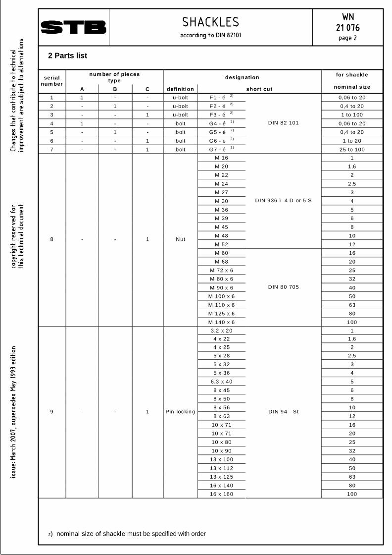
num ber of pieces type designation serial
num ber A B C definition short cut
for shackle
nom inal size
1 1 - - u-bolt F1 - … 2) 0,06 to 20 2 - 1 - u-bolt F2 - … 2) 0,4 to 20 3 - - 1 u-bolt F3 - … 2) 1 to 100
4 1 - - bolt G4 - … 2) 0,06 to 20 5 - 1 - bolt G5 - … 2) 0,4 to 20 6 - - 1 bolt G6 - … 2) 1 to 20 7 - - 1 bolt G7 - … 2)
D IN 82 101
25 to 100 M 16 1 M 20 1,6 M 22 2
M 24 2,5 M 27 3 M 30 4 M 36 5 M 39 6 M 45 8 M 48 10 M 52
DIN 936 – 4 D or 5 S
12 M 60 16 M 68 20
M 72 x 6 25 M 80 x 6 32
M 90 x 6 40 M 100 x 6 50 M 110 x 6 63 M 125 x 6 80
8 - - 1 Nut
M 140 x 6
DIN 80 705
100 3,2 x 20 1 4 x 22 1,6 4 x 25 2 5 x 28 2,5 5 x 32 3 5 x 36 4
6,3 x 40 5 8 x 45 6 8 x 50 8 8 x 56 10 8 x 63 12
10 x 71 16 10 x 71 20 10 x 80 25 10 x 90 32
13 x 100 40
13 x 112 50 13 x 125 63 16 x 140 80
9 - - 1 Pin-locking
16 x 160
DIN 94 - St
100
2) nominal size of shackle must be specified with order
2 Parts list