Embed Size (px)
Citation preview

FACULTY OF TECHNOLOGY
LUT ENERGY
ELECTRICAL ENGINEERING
MASTER’S THESIS
IMPACT OF UNSYMMETRICAL LOADS IN DISTRIBUTION NETWORKS
Examiners Prof. Jarmo Partanen
Prof. Evgeniy Popkov
Author Mansur Gapuev
LAPPEENRANTAUNIVERSITY OF TECHNOLOGY
PDF created with pdfFactory Pro trial version www.pdffactory.com
2
Abstract
Lappeenranta University of Technology
Faculty of Technology
Electrical Engineering
Gapuev Mansur
Impact of unsymmetrical loads in distribution networks
Master’s thesis
2009
70 pages
Examiners: Professor J. Partanen and E. Popkov
Keywords: Distribution networks, voltage unbalance, unsymmetrical load, trans-
former.
Since it is virtually impossible to balance loads in three-phase system, unbal-
ance in a varying degree exists almost in all distribution networks. The aim of
the thesis is to analyze the impact of this unbalance subject to different configu-
rations of distribution system and winding connection of the supplying trans-
former. Also impact of the voltage unbalance on the equipment is investigated.
In order to make the investigation more visual, the following calculations
have been conducted:
− Unsymmetrical load in four-wire star connected network
− Unsymmetrical load in four-wire star connected network with broken
zero conductor (or three-wire network).
− Unsymmetrical load when the supplying transformer is so-called zigzag
transformer.
PDF created with pdfFactory Pro trial version www.pdffactory.com

3
Acknowledges
This master’s thesis was carried out at the department of Electrical Engineering,
Lappeenranta University of Technology
I would like to express my deepest gratitude to the supervisor of this thesis,
Professor Jarmo Partanen, and also to all department of Electrical Engineering,
who helped me to deep my knowledge in the field of electrical engineering. As
well as I wish to say thank to my second supervisor D. Kuleshov for his help by
word and deed.
Special thanks to Julia Vauterin for her help and support during my studies.
And I am very grateful to my family: my father Danil Gapuev, mother Malika
Gapueva, to my brother and sisters, to my brother`s wife…. Who has not left me
for a moment without support.
Lappeenranta, May 2009 Mansur Gapuev
PDF created with pdfFactory Pro trial version www.pdffactory.com

4
Table of contents
Abstract
Acknowledgements
Table of contents....................................................................................................4
Abbreviations and symbols..............................................................................6
1 Introduction...........................................................................................................9
1.1 The history of evolution of distribution systems................................................9
1.2 Distribution network configuration............................................................11
1.3 Different types of distribution systems used worldwide............................12
1.4 Summary.....................................................................................................15
2 Theory (symmetrical components) of load flow calculations for
unsymmetrical situations.................................................................17
2.1 Sources of voltage unsymmetry and the ways to reduce it........................17
2.2 Consequences of unsymmetrical situations......................................................17
2.3 Theory of symmetrical components for unsymmetrical situations.............19
2.4 Summary....................................................................................................23
3 Mathematical equations for calculating the load flow (currents,
voltages, losses).................................................................................24
3.1 Short review of the simplest equations..............................................................25
3.2 Load flow calculations in radial and simple loop networks .....................28
3.3 Load flow calculations for large systems...................................................31
3.4 Summary....................................................................................................36
PDF created with pdfFactory Pro trial version www.pdffactory.com
5
4 Case study calculations.................................................................37
4.1 introduction to the calculations………………………………………….37
4.2 Unsymmetrical situation with four-wire delta-star with grounding connec-
tion of transformer's secondary………………………………………….......38
4.3 Unbalanced situation with broken zero conductor……………………....47
4.4 Unbalanced situation when supplying via zig-zag transformer………….53
5 Analysis of impact of unsymmetrical loads (depending on vetor
group of mv/lv transformer) and quality of voltage.....................54
5.1 Transformers and their role in distribution systems..................................54
5.2 Analysis of impact of unsymmetrical loads depending on vector group of
mv/lv transformers...........................................................................................56
5.3 Quality of voltage and its importance for consumers...................................63
5.4 Distortion of voltage, higher voltage drop and power losses......................64
5.5 Higher voltage drop and power losses.........................................................67
5.6 Summary....................................................................................................68
6 Conclusion......................................................................................69
References.................................................................................................................70
PDF created with pdfFactory Pro trial version www.pdffactory.com

6
Abbreviations and symbols
Roman letters
a Operator
B Capacitive susceptance
e Electromotive force
J Jacobian matrix
I Current
I Current matrix
IA0,IB0,IC0 Zero-sequence currents
IA1,IB1,IC1 Positive-sequence currents
IA2,IB2,IC2 Negative-sequence currents
k0 Coefficient unsymmetry by zero-sequence
k2 Coefficient unsymmetry by negative-sequence
l Line length
L Inductance
rl Per-kilometer resistance
rk Short circuit resistance
R Resistance
Rk Resistance of the transformer
P Active power
Q Reactive power
S Apparent power
U Voltage
U Voltage matrix UA0,UB0,UC0 Zero-sequence voltages UA1,UB1,UC1 Positive-sequence voltages UA2,UB2,UC2 Negative-sequence voltages
xl Per-kilometer reactance
xk Short circuit reactance
PDF created with pdfFactory Pro trial version www.pdffactory.com
7
X Reactance
Xk Reactance of the transformer
Y Bus admittance matrix
yij Elements of admittance matrix
Z Impedance
Zk Impedance of the transformer
Greek letters
ϕ Angle between voltage and current
δ Angle between beginning and end.
Subindexes
add Additional
eqv Equivalent
GRD Grounded
L Line voltage
L Load
n Nominal
p Phase voltage
D Delta connection
S Star connection
Acronyms
AC Alternating current
cos (φ) Power factor
D,∆ Delta connection
DC Direct current
DS Distribution system
PDF created with pdfFactory Pro trial version www.pdffactory.com
8
HV High voltage
LV Low voltage
MV Medium voltage
N,n Neutral
NR Newton-Raphson
NEMA National Electrical Manufacturers Association
PE Protective earth
SWER Single wire earth return systems
SCADA Supervisory for Control And Data Acquision
SCR Silicon controlled rectifier
THD Total harmonic distortion
TT Direct connection of a point with earth, direct connection with
earth, independent of any other earth connection in the supply system
TN-S PE and N are separate conductors that are connected together
only near the power source
TN-C-S Part of the system uses a combined PEN conductor, which is at
some point split up into separate PE and N line.
TN-C A combined PEN conductor fulfills the functions of both a PE
and N conductor
Y Star connection
Z Zigzag connection
PDF created with pdfFactory Pro trial version www.pdffactory.com

9
Introduction
Electricity is one of the most important components of the development of the
modern society. We cannot imagine our life without electric lighting, habitual
electric devices, electric heating and conditioning. Some present-day devices
need qualitative electricity for correct and long work. In simple words, power
quality can be characterised by sinusoidal voltage source, without waveform
distortion, variation in amplitude or frequency.
A distribution system's network carries electricity from the transmission sys-
tem and delivers it to consumers. Typically, the network includes medium-
voltage (less than 50 kV) power lines, electrical substations and usually pole-
mounted transformers, low-voltage (less than 1000 V) distribution wiring and
sometimes electricity meters.
One of the main characteristics of distribution system is reliability. Reliability
characterises the ability of the system to withstand to one or another anomalous
situation. Anomalous situation can be different in type, seriousness, time of ac-
tion. One of the most widespread anomalous situations in distribution systems is
unsymmetrical situations which often happen because of unsymmetrical loads,
short circuits in one or two phase and some other reason, about which will be
said later.
In the thesis the all above-mentioned issues are investigated.
1.1 The history of evolution of distribution systems
At the very beginning of electricity generation, direct current (DC) genera-
tors were connected to loads at the same voltage, as at the time it was not known
the efficient way to transform the level of DC voltage. The voltages had to be
significantly low with such systems because it was difficult and dangerous to
distribute high voltages to small loads. As we know, the losses in a conductor are
proportional to the square of the current, the length of the conductor, and the
resistivity of the material, and are inversely proportional to cross-sectional area.
PDF created with pdfFactory Pro trial version www.pdffactory.com

10
Early transmission networks were already from copper conductors, which is one
of the best economically and technically feasible conductors for this application.
To decrease the current while keeping power transmission constant requires in-
creasing the voltage which, as previously mentioned, was problematic. This
meant in order to keep losses to a reasonable level the Edison system needed
thick cables and a lot of local generators to provide with electricity large area. .
Because of above-listed reasons, the transmission/distribution systems were not
extended from the point of generation and were within about 1.5 miles (2.4 km).
The most considerable changes in the electricity generation and transmission
occurred after the adoption of alternating current (AC) following the War of Cur-
rents. Power transformers, installed at substations, enabled to raise the voltage
from the generators and reduce it to supply loads. The higher voltage the lower
current was necessary in the transmission and distribution lines and consequently
Fig.1.1. Overview of the power system from generation to consumer's switch
PDF created with pdfFactory Pro trial version www.pdffactory.com

11
the size of conductors required and distribution losses incurred. This made it
more economic to distribute power over long distances with acceptable losses.
The ability to transform to extra-high voltages enabled generators to be located
far from consumers with transmission systems to interconnect generating stations
and distribution networks. Early distribution systems in North America used a
voltage of 2200 volts corner-grounded delta. Gradually this was increased to
2400 volts. As cities grew, most 2400 volt systems were upgraded to 2400/4160
Y three-phase systems, which also benefited from better surge suppression due
to the grounded neutral. Some city and rural distribution systems continue to use
this range of voltages, but most have been converted to 7200/12470Y.
European systems used higher voltages, generally 3300 volts to ground, in
support of the 220/380Y volt power systems used in those countries. In the UK,
urban systems progressed to 6.6 kV and then 11 kV (phase to phase), the most
common distribution voltage.
1.2 Distribution network configuration
Distribution networks can be divided into two types - radial and intercon-
nected. The difference between them is that the radial network leaves the station
and passes through the network area without any connection to other supply. It is
more typical for long rural lines with isolated load areas. Interconnected net-
works have multiple connections to other points of supply and can be mainly met
in urban areas.
The interconnected model is more desirable in the areas with important cus-
tomers, such as, for example, hospitals or industry. In case of fault situations or
required maintenance, the out-of-order area can be separated from undamaged
part by opening the switches. Operation of these switches may be by remote con-
trol from a control centre or by a lineman.
Distribution networks are usually performed in the form of overhead lines
with traditional utility poles and wires and, increasingly, underground construc-
PDF created with pdfFactory Pro trial version www.pdffactory.com

12
tion with cables and indoor substations. Although, underground distribution is
significantly more expensive than overhead construction, they are used when it is
not eligible to use the overhead lines (For example, in urban areas with expen-
sive cost of the land). Distribution feeders emanating from a substation are gen-
erally controlled by a circuit breakers which will open when a fault is detected.
Automatic Circuit Reclosers may be installed to further separate the feeder thus
minimizing the impact of faults.
The main characteristics of electricity supply to customers are listed below:
• AC or DC - Virtually all public electricity supplies are AC today. Users of
large amounts of DC power such as some electric railways, telephone ex-
changes and industrial processes such as aluminium smelting usually either
operate their own or have adjacent dedicated generating equipment, or use
rectifiers to derive DC from the public AC supply
• Voltage, including tolerance (usually +10 or -15 percentage)
• Frequency, commonly 50 & 60 Hz, 16-2/3 Hz for some railways and, in a
few older industrial and mining locations, 25 Hz. [1]
• Phase configuration (single phase, polyphase including two phase and
three phase)
• Maximum demand (usually measured as the largest amount of power de-
livered within a 15 or 30 minute period during a billing period)
• Load Factor, expressed as a ratio of average load to peak load over a pe-
riod of time. Load factor indicates the degree of effective utilization of
equipment (and capital investment) of distribution line or system.
• Power factor of connected load
• Maximum prospective short circuit current
• Maximum level and frequency of occurrence of transients
• Earthing arrangements - TT, TN-S, TN-C-S or TN-C
Different types of earthing arrangements are shown in the figure 1.2
PDF created with pdfFactory Pro trial version www.pdffactory.com

13
Fig.1.2. Earthing arrangements. a) TN-S: separate protective earth (PE) and neutral (N) conductors from transformer to consuming device, which are not connected together at any point after the building distribution point. b) TN-C: combined PE and N conductor all the way from the transformer to the consuming device. c) TN-C-S earthing system: combined PEN conductor from transformer to building distribution point, but separate PE and N conductors in fixed indoor wiring and flexible power cords. d) TT, the protective earth connection of the consumer is provided by a local connection to earth, independent of any earth connection at the generator.
1.3 Different types of distribution systems used worldwide
In different countries, in process of evolution of distribution systems, there
have appeared some differences among them. There are such differences be-
tween European and North American distribution systems, between British and
Norwegian and so on. Of course, every DS has its own advantages and disadvan-
tages as compared to the others [6].
PDF created with pdfFactory Pro trial version www.pdffactory.com

14
In the North American distribution system in a MV network, a neutral con-
ductor is used, which is earthed at the distance of 300m. As well, the branch
lines are usually single-phase or two phase.
There are circuit breakers on the main lines, on the branch-offs, there are
fuses and sectionalizers that automatically open the circuit when a fault occurs.
And, another thing is transformer. The transformers are single-phase con-
struction, and they are coupled between the phase and the neutral.
The British distribution system differs from the American system for exam-
ple, by the fact that neutral point of the supplying transformers is earthed through
a resistance. Distribution systems of low rated distribution transformers are
three phase units. In the traditional British system, there are two medium-
voltages in the same geographic region: 33 kV and 11 kV. Underground cabling
is more common than in America, although less common than in the western
continental Europe. The phase voltage in the low-voltage side is 240 V. Residen-
tial areas built up with single-family houses and terrace houses are often supplied
with a sturdy three-phase low-voltage cable, from which short, single phase ser-
vice lines leave at fixed connections.
In the traditional Norwegian distribution system the neutral point of the
secondary winding is not earthed, there is no neutral conductor in the distribution
line, and the 230 V equals to the phase to phase voltage. The frames of the load
equipment are earthed, although this practise is gradually disappearing.
In Finland, in installation inside buildings, the neutral from the transformer
substation has traditionally been used as the return conductor of the single phase
loads. Traditionally, the neutral has also been connected to the conductive frames
of devices (neutral as protective earthing), although from 1990 this practise has
been replaced by so-called five conductor system, in which a separate protective
conductor from the main distribution board of the building is coupled to the
frames of the devices.
The five conductor system enables indicating of a low current earth contact.
North American and European power distribution systems also differ in that
North American systems tend to have a greater number of low-voltage, step-
down transformers located close to customers' premises. For example, in the US
PDF created with pdfFactory Pro trial version www.pdffactory.com

15
a pole-mounted transformer in a suburban setting may supply 1-3 houses,
whereas in the UK a typical urban or suburban low-voltage substation would
normally be rated between 315kVA and 1000kVA (1MVA) and supply a whole
neighbourhood. This is because the higher voltage used in Europe (415V vs.
230V) may be carried over a greater distance with acceptable power loss. An
advantage of the North American setup is that failure or maintenance on a single
transformer will only affect a few customers. Advantages of the UK setup are
that the transformers may be fewer, larger and more efficient, and due to diver-
sity there need be less spare capacity in the transformers, reducing power wast-
age. In North American city areas with many customers per unit area, network
distribution will be used, with multiple transformers and low-voltage busses in-
terconnected over several city blocks.
Rural Electrification systems, in contrast to urban systems, tend to use higher
voltages because of the longer distances covered by those distribution lines. 7200
volts is commonly used in the United States; 11 kV and 33 kV are common in
the UK, New Zealand and Australia; 11 kV and 22 kV are common in South
Africa. Other voltages are occasionally used in unusual situations or where a
local utility simply has engineering practices that differ from the norm.
In New Zealand, Australia, Saskatchewan, Canada and South Africa, single
wire earth return systems (SWER) are used to electrify remote rural areas.
1.4 Summary
In the process of engineering of new electrical transmission and distribution
networks it is essential to choose the appropriate system design philosophy in
order to correspond to the local social and economic conditions. It applies also to
reinforcement or replacement of the outdated networks, although in this situation
there exist some previous groundwork.
PDF created with pdfFactory Pro trial version www.pdffactory.com

16
Changing from one practice of building of distribution systems (for example,
from UK type to USA), even if better in some parameters, is seldom economi-
cally justified, at least in the short term.
PDF created with pdfFactory Pro trial version www.pdffactory.com

17
2 Theory (symmetrical components) of load flow calculation
for unsymmetrical situations.
As it was said previously, one of the reasons of deterioration of the quality of
electrical supply is unsymmetrical situations. Unsymmetrical situations are unde-
sirable disturbance in work of distribution systems which occur mainly because
of unsymmetrical loads or short circuit. Below unsymmetrical situations pro-
duced by unsymmetrical loads, consequences of unsymmetrical situations and
the ways to avoid them will be described.
2.1 Sources of voltage unsymmetry and the ways to reduce it
The main sources of voltage unsymmetry are arc steel-smelting furnaces,
traction substations of alternating current, electric welding machines, single-
phase thermal electric installations or any powerful single-phase, two-phase or
three-phase unsymmetrical consumers of electric power, including domestic. For
example, the summary load of some factories contain 85....90% unsymmetrical
load. Thus, coefficient of unsymmetry by zero-sequence (k0U) a nine-storied in-
habited building can amount to 20%, which on the substation busses (the point of
common joining), can exceed normally admissible 2%.
The main ways to avoid the unsymmetry are
• Uniform distribution of loads in the phases
• Application of the symmetric installations
2.2 Consequences of unsymmetrical situations
The main disadvantage of unsymmetrical situations is that they bring to un-
symmetry of voltage. Unsymmetrical load currents flowing through elements of
electrical supply cause unsymmetrical voltage drop. As a consequence, there
appears an unsymmetrical system of voltages on the leads of the electrical re-
ceiver. Deviation of voltage of overloaded phase can exceed admissible level,
when the deviation of voltages of the rest can be within normal limits. Besides
PDF created with pdfFactory Pro trial version www.pdffactory.com

18
the deterioration of the voltage, under unsymmetrical situations the conditions of
work of electrical receivers and the most of elements of distribution network
become much worse, also the reliability of the whole system decreases.
Unsymmetrical situations influence considerably on the mode of operation of
asynchronous motors, the widespread three-phase electrical receivers, for
which the particular significance has a voltage of negative sequence. Resistance
of negative sequence of electric motors is equal to resistance of braked motor;
consequently, it is in 5-8 times less then resistance of positive-sequence. There-
fore, even not large unsymmetry of the voltages causes considerable currents of
negative sequence. They superimpose on the currents of positive-sequence and
produce the additional heating of the stator and the rotor (especially massive part
of the rotor), which, in turn, results in rapid ageing of the isolation and decrease
of available power of the motor (decrease of the efficiency). For example, the
lifetime of the completely loaded asynchronous motor, working under unsym-
metry of the voltage about 4% shortens in two times. Under unsymmetry of volt-
age 5%, available power decreases to 5-10%.
Under unsymmetry of the voltages, in synchronous machines besides the
rise of additional losses of active power and heating of the stator and the rotor,
there may arise dangerous vibrations as a result of appearance sign-changing
rotating moments and tangential forces, pulsating with double frequency of the
network. When the unsymmetry is considerable, the vibration may be dangerous,
in particular if the durability of the details is not sufficient and there are defects
in the welded connection. When the unsymmetry of the currents does not exceed
30%, the dangerous overstrains, as a rule, do not appear.
In case of presence of direct-sequence and negative-sequence currents, the
summary currents in separate phases of the distribution networks increase,
which brings to increase of the losses, which is usually not permissible in view
of heating. The currents of zero-sequence always flow through grounding elec-
trode. It dries out and increases the resistance of grounding elements. It can be
inadmissible from the point of view of working the relay protection, as well as
because of strengthening impact on low-frequency communication settings and
means of the railway blockage.
PDF created with pdfFactory Pro trial version www.pdffactory.com

19
The voltage unsymmetry noticeably worsens the mode of operation of the
multiphase gated rectifiers: the rippling of the rectified voltage considerably
increases the conditions of work of the thyristor converters also deteriorate.
Under unsymmetrical voltages, condenser installations load by reactive
power irregularly from each phase, which makes impossible using rated con-
denser power. In addition, in this case condenser installations strengthen already
existing unsymmetry, as the output of the reactive power into network in phase
with the least voltage will be lower, than in the other phases (proportionally to
the square of the voltage on the condenser installation).
Unsymmetry of the voltage also influenced monophase electric receivers. For
example, if the phase voltages are not equal, incandescent lamps, connected to
the phase with higher voltage have bigger luminous flux, but considerably lower
lifetime as compared with lamps, connected to the phase with lower voltage.
Unsymmetry of voltages also complicate functioning of the relay protection,
leads to errors in operation of the electricity meters and so on.
The general influence of unsymmetrical voltages on the electrical machines,
different devices, lamps, conductors, transformers is considerable decrease of
their lifetime.
2.3 Theory of symmetrical components for unsymmetrical situations
The theory of symmetrical components allows comparatively simplify com-
putation of unsymmetrical situations. The essence of this theory is that any un-
symmetrical three-phase system of vectors (currents, voltages) can be
represented as three symmetrical systems. One of them has a positive sequence
of phase interlacing (A1 → B1 → C1), the other has negative (A2 → C2→ B2).
The third system is called zero-sequence system and consists of three equal vec-
tors, coinciding in phase (A0, B0, C0) [8].
Thus, for each phase one can write
A = A1 + A2 + A0
B = B1 + B2 + B0 (2.1)
C = C1 +C2 + C0
PDF created with pdfFactory Pro trial version www.pdffactory.com

20
The system of quantities of positive sequence
A1; B1 = A1 a 2; C1 = A1 a . (2.2a)
The system of quantities of negative sequence
A2; B2 = A2 a ; C2 = A2 a 2. (2.2b)
The system of quantities of zero sequence
A0 = B0 = C0 (2.2c)
Fig. 2.1. Symmetrical components.
Multiplication the vector by a means its rotation to 1200 contraclockwise.
The rotation the vector to 2400 can be represented by multiplying it by a 2.
where a is operator,0120jea = , or in complex form
1 32 2
a j= − + (2.3)
In complex number theory, we defined j as the complex operator which is
equal to √-1 and a magnitude of unity, and more importantly, when operated on
any complex number rotates it anti-clockwise by an angle of 900
I.e. j = √-1
For the operator, these equations hold true
2 1 0a a+ + =
3 2
4 3
1ja ea a a a
π= =
= = (2.4)
PDF created with pdfFactory Pro trial version www.pdffactory.com

21
The first equation from (2.4) is shown on the fig. 2.2
Fig. 2.2.Phasor addition
From the equations (2.2) it follows, that when we use the method of symmet-
rical components, it is enough to calculate the values for any single phase, for
example A, after which it is not difficult to determine the symmetrical compo-
nents for the rest two phases and the whole values of respective phase values,
that is:
A = A1 + A2 + A0
B = A1 a 2+ A2 a + A0 (2.5)
C = A1 a + A2 a 2 + C0
Thus, instead of one unsymmetrical circuit, one calculates three, but consi-
derably more easier, which makes the whole calculation significantly simpler.
The symmetrical components of the phase A, for example, can be derived if
one knows the whole values of the phase quantities. The equation for determina-
tion the component A1 can be obtained by multiplication the second and third
equations of the system (2.5) by a and a 2 respectively and following summation
of all equations of this system. As a result, we will get
( )2a a11A = A + B + C3 (2.6a)
Similarly, the equation for determination the component A2 can be obtained
by multiplication the second and third equations of the system (2.5) by a and a 2
respectively and following summation of all equations of this system. As a re-
sult, we will get
( )2a a21A = A + B + C3
(2.6b)
PDF created with pdfFactory Pro trial version www.pdffactory.com

22
The equation for determination A0 can be obtained by summation the all three equations of the system (2.5)
( )01A = A + B + C3
(2.6c)
By application of the equations (2.6), it is not difficult to determine the sym-
metrical components of given system of vectors and graphical way as it is shown
on the figure 2.3.
Fig.2.3. Graphical construction for the determination of symmetrical components
Geometrical vector sums of the positive and negative sequences of three
phases, as for any balanced systems, are equal to zero. As opposed to this, the
system of quantities of zero-sequence, as it follows from (2.2) is not balanced,
that is
A0 + B0 + C0 = 3 A0 ≠ 0 (2.7)
All above mentioned equations hold true for currents and voltages under un-
symmetrical situations in any three-phase electrical installations.
Unsymmetrical currents, flowing in phases of the circuit, cause unsymmetri-
cal voltage drop in the resistances of the phases, which can be decomposed into
symmetrical components. The voltage drop of positive sequence is caused by the
current of positive sequence; the voltage drop of negative sequence is caused by
the current of the negative sequence and so on, that is, the current of each se-
quence creates the voltage drop of respective sequence.
For different sequences the resistances of the elements of three-phase circuit
can differ by values.
PDF created with pdfFactory Pro trial version www.pdffactory.com

23
2.4 Summary
As one can see the voltage unbalance is very dangerous on the one side and
cause great losses in different equipment on the other. Also it worsens the mode
of operation of some instalments such as multiphase gated rectifiers. So the rate
of unbalance should be kept in acceptable ranges. To do this, the level of unbal-
ance should be calculated by one or another method.
The solution of unbalanced electrical circuits is considerably easy with the
method of symmetrical components and in the case of extended networks it is the
only acceptable method. It is very powerful analytical tool which is used by a
great number of computing programs.
The unbalance can be avoided if to distribute the loads in the phases in the
appropriate way. Also there exist some balancing instalments to level out the
unbalance.
PDF created with pdfFactory Pro trial version www.pdffactory.com

24
3 Mathematical equations for calculating the load flow (cur-
rents, voltages, losses)
Mathematical equations for calculating the load flow can be used both in
manual and automatic calculations of the state of the electric networks. The load
flow calculations are fulfilled in order to keep the system running in a stable and
safe state and are used to determine possible or optimal choice of the network’s
components (transformers’ voltage regulators, automatic control settings of the
machine regulators). The determining inputs are usually the voltages and/or cur-
rents and/or the active/reactive power at the consumer’s port. Conductors - over-
head lines and cables – are important elements, so, on the one hand, the reason of
such calculations to find out, whether they will withstand such a state in normal
conditions, and, from the other hand, to find out their influence on the load flow.
In order to carry out load flow calculations in a simple way, it is common prac-
tice to use as few circuit elements as is possible for the given task. In the case of
low voltage lines in most cases an ohmic resistance will do and even for high
voltage lines in most cases the longitudinal impedance is taken into considera-
tion.
As it said above, the power flow calculations are conducted to find out the
best solutions for constructing and maintenance of the electric networks. During
the load flow studies there used both initial data and some special methods for
finding out one or several unknown parameters of the networks.
For different elements of power energetic there is a different set of initial pa-
rameters [7].
Ø Power plants
• Supplied active power Pg
• Terminal voltage U, to be maintained at the plant
• Reactive power generation and consumption capacity (Qmax, Qmin)
Ø Lines
• Impedances of the equivalent circuit (R, jX, G, jB)
Ø Transformers
PDF created with pdfFactory Pro trial version www.pdffactory.com

25
• Short-circuit impedance (Rk, jXk)
Ø Compensation devices (compensators)
• Impedance (R, jX)
Ø Loads
• Active and reactive power (P, jQ)
Besides the constant parameters of network, there are varying amount of con-
troller data:
Ø On-load tap-changer data (position, number and size of the steps)
• Is stepping automatic; if so, on what criterion?
Ø Control principles of compensators
Ø Power of interconnectors between subsystems
• Regulating power plants
Ø Control principles for DC links (Finland-Sweden, Finland-Russia)
Also, in the calculations, there used following control parameters:
Ø method, convergency criterion, number of iterations, blockings
(Tap changers, compensators)
At the beginning of this chapter, the most common equations for single-phase
and three-phase circuits will be reviewed and after that load flow equations are
described.
3.1 Short review of the simplest equations
In a balanced three phase system, knowledge of one of the phases gives the
other two phases directly. However this is not the case for an unbalanced supply.
In a star connected supply, it can be seen that the line current (current in the line)
is equal to the phase current (current in a phase). However, the line voltage is not
equal to the phase voltage. The line voltages are defined as
URY = UR – UY,
UYB = UY – UB, (3.1)
UBR = UB – UR.
PDF created with pdfFactory Pro trial version www.pdffactory.com

26
Figure 3.1(a) shows how the line voltage may be obtained using the normal
parallelogram addition. It can also be seen that triangular addition (Fig3.1 (b))
also gives the same result faster.
Fig 3.1. Parallelogram (a) and triangular (b) additions. For a balanced system, the angles between the phases are 1200
and the magni-
tudes are all equal. Thus the line voltages would be 300 leading the nearest phase
voltage. Calculation will easily show that the magnitude of the line voltage is √3
times the phase voltage.
IL = IP, |UL|= √3 |UP| , |IL| = √ 3|Id| (3.2)
Similarly in the case of a delta connected supply, the current in the line is √3
times the current in the delta.
It is important to note that the three line voltages in a balanced three phase
supply is also1200 out of phase, and for this purpose, the line voltages must be
specified in a sequential manner. i.e. URY, UYB and UBR. [Note: UBY is 1800 out of
phase with VYB so that the corresponding angles if this is chosen may appear to
be 600 rather than 1200].
A balanced load would have the impedances of the three phase equal in mag-
nitude and in phase. Although the three phases would have the phase angles dif-
fering by 1200 in a balanced supply, the current in each phase would also have
phase angles differing by 1200 with balanced currents. Thus if the current is lag-
PDF created with pdfFactory Pro trial version www.pdffactory.com
27
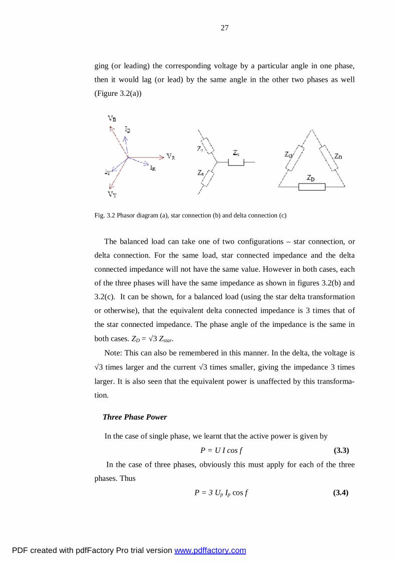
ging (or leading) the corresponding voltage by a particular angle in one phase,
then it would lag (or lead) by the same angle in the other two phases as well
(Figure 3.2(a))
Fig. 3.2 Phasor diagram (a), star connection (b) and delta connection (c)
The balanced load can take one of two configurations – star connection, or
delta connection. For the same load, star connected impedance and the delta
connected impedance will not have the same value. However in both cases, each
of the three phases will have the same impedance as shown in figures 3.2(b) and
3.2(c). It can be shown, for a balanced load (using the star delta transformation
or otherwise), that the equivalent delta connected impedance is 3 times that of
the star connected impedance. The phase angle of the impedance is the same in
both cases. ZD = √3 Zstar.
Note: This can also be remembered in this manner. In the delta, the voltage is
√3 times larger and the current √3 times smaller, giving the impedance 3 times
larger. It is also seen that the equivalent power is unaffected by this transforma-
tion.
Three Phase Power
In the case of single phase, we learnt that the active power is given by
P = U I cos φ (3.3)
In the case of three phases, obviously this must apply for each of the three
phases. Thus
P = 3 Up Ip cos φ (3.4)
PDF created with pdfFactory Pro trial version www.pdffactory.com

28
However, in the case of three phases, the neutral may not always be available
for us to measure the phase voltage. Also in the case of a delta, the phase current
would actually be the current inside the delta which may also not be directly
available.
It is usual practice to express the power associated with three phase in terms
of the line quantities. Thus we will first consider the star connected load and the
delta connected load independently.
For a balanced star connected load with line voltage UL and line current IL,
Lstar 3
UU = , I star = IL (3.5)
star Lstar
star L3U UZI I
= =
Sstar = 3UstarIstar = √3ULIL (3.6)
Thus,
Pstar = √3ULIL cos φ, (3.7a)
Qstar = √3ULIL sin φ (3.7b)
It is worth noting here, that although the currents and voltages inside the star
connected load and the delta connected loads are different, the expressions for
apparent power, active power and reactive power are the same for both types of
loads when expressed in terms of the line quantities.
Thus for a three phase system (in fact we do not even have to know whether it
is a load or not, or whether it is star-connected or delta-connected)
Apparent Power S = √ 3ULIL (3.8a)
Active Power P = √ 3ULIL cos φ (3.8b)
Reactive Power Q = √ 3ULIL sin φ (3.8c)
PDF created with pdfFactory Pro trial version www.pdffactory.com

29
3.2 Load flows in radial and simple loop networks
In radial networks the phase shifts due to transformer connections along the
circuit are not usual important because the currents and voltages are shifted by
the same amount.
Fig.3.3. Feeder with several load tappings
In figure 3.3 one can see a distribution feeder with several tapped inductive
loads (or laterals) and fed at one end. The total voltage drop in this situation is
determined by the next way. At first, we determine the current in AB
AB = (I1cos (ϕ1) + I2 cos (ϕ2) + I3 cos (ϕ3) + I4 cos (ϕ4) –
j ( I1 sin (ϕ1) + I2 sin (ϕ2) +I3 sin (ϕ3) + I4 sin (ϕ4))
The currents in the other sections of the feeder are obtained by the same way.
And now, it is not difficult to determine the voltage drop from the equation
∆U = RI cos (ϕ) + XI sin (ϕ) (3.9)
for each section. That is
R1 (I1cos (ϕ1) + I2 cos (ϕ2) + I3 cos (ϕ3) + I4 cos (ϕ4))
+ R2 (I2 cos (ϕ2) + I3 cos (ϕ3) + I4 cos (ϕ4) + R3 (I3 cos (ϕ3) + I4 cos (ϕ4)
+ R4 (I4 cos (ϕ4) + X1 (I1 sin (ϕ1) + I2 sin (ϕ2) +I3 sin (ϕ3) + I4 sin (ϕ4)) and so on
If the resistance per loop metre (the term loop meter refers to single phase cir-
cuit and includes the go and return conductors) is r ohms and reactance per loop
metre is x ohms, we have
PDF created with pdfFactory Pro trial version www.pdffactory.com

30
∆U = r (I1 · l1 cos (ϕ1) + I2 cos (ϕ2) · (l1+l2) + I3 cos (ϕ3) · (l1+l2+l3)
+ I4 cos (ϕ4) · (l1+l2+l3+l4)) + x (I1 l1sin (ϕ1) + I2 sin (ϕ2) · (l1+l2)
+I3 sin (ϕ3) · (l1+l2+l3) + I4 sin (ϕ4) · (l1+l2+l3+l4))
Load flows in closed loops. In a closed loop in order to avoid the circulating
currents, the product of the transformer transformation ratios round the loop
should be unity and the sum of the phase shifts in a common direction round the
loop should be zero. This is illustrated in the figure 3.4.
Fig.3.4. Loop with transformer phase shift.
In this example
33 13.8 13230 30 0 1 0132 33 13.8
o o o o ∠ ⋅ ∠ − ⋅ ∠ = ∠
In practice the transformation ratios of transformers are often changed by
means of tap-changing equipment. This results in the product of the ratios round
the loop being no longer unity, although the phase shifts are still equal to zero.
An undesirable effect in circulating current set up around the loop
Frequently the out-of-balance or remnant voltage represented by the auto-
transformer can be neglected. If this is not the case, the best method of calcula-
tion is to determine the circulating current and consequent voltages due to the
remnant voltage acting alone, and then superpose these values on those obtained
for operation with completely nominal voltage ratios.
PDF created with pdfFactory Pro trial version www.pdffactory.com

31
3.3 Load flow calculations for large systems
The most widespread methods of solving large systems are Gauss-Seidel, which has been used for many years and is simple in approach and Newton-Raphson methods, which although more complex has certain advantages.
Fig. 3.5. Single node
From Ohm`s law
(3.10) Si = Ui ⋅ Iij Sj = Uj ⋅ Iij Sh = I2
ij⋅ Zij (3.11) To find the voltage in different nodes we can use Kirchhoff’s 1st Law
(3.12)
Fig.3.6. To load flow calculations
PDF created with pdfFactory Pro trial version www.pdffactory.com
32
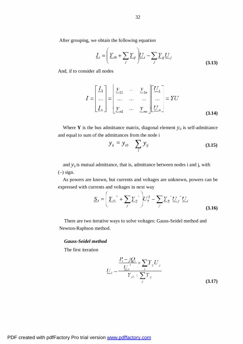
After grouping, we obtain the following equation
(3.13)
And, if to consider all nodes
(3.14) Where Y is the bus admittance matrix, diagonal element yii is self-admittance and equal to sum of the admittances from the node i
0ii i ij
jy y y= + ∑
(3.15)
and yij is mutual admittance, that is, admittance between nodes i and j, with (–) sign. As powers are known, but currents and voltages are unknown, powers can be expressed with currents and voltages in next way
(3.16)
There are two iterative ways to solve voltages: Gauss-Seidel method and Newton-Raphson method. Gauss-Seidel method
The first iteration
(3.17)
PDF created with pdfFactory Pro trial version www.pdffactory.com

33
And we continue with the new values for voltage until the difference in vol-
tages between the consecutive iterations is small enough. The disadvantage of
this method is that it converges slowly.
Gauss-Seidel acceleration factors
In order to speed up the convergence, the correction in voltage is multiplied
by the constant ω
U p+1 =U p +ω (U p+1 −U p ) =U p +ωΔU p (3.18) Which depends on the concrete network and usually equal to 1,6.
Newton-Raphson method
In this method, we assume f(x) = 0, and then make initial guess x0 and find
Δx1 such that f(x0 + Δx1) = 0. From the Taylor series
f(x0) + f´(x0)Δx1 = 0 (3.19)
(3.20) Where J is the Jacobian matrix
Then the process is repeated with the value x1 = x0 + Δx1 if there are several
equations fi(x1...xn) = 0 i = 1...n
(3.21)
For load nodes we have the following power equations:
PDF created with pdfFactory Pro trial version www.pdffactory.com

34
(3.22) At the beginning, we make guesses for voltages (absolute value and angle).
After that we calculate Pi and Qi with the above equations, and compare them
with the actual initial data (P, Q) → mismatch (ΔP and ΔQ). Then corrections in
voltages are calculated (absolute values and angles) by applying Newton-
Raphson method so that ΔP and ΔQ converge as much as possible. And this
process is repeated until ΔP and ΔQ are small enough.
This method is mathematically difficult, but converges fast. So, it is the most
common method.
For nodes we have the following power equations:
(3.23)
Or alternative representation:
(3.24)
In the NR method for load flow studies, correction in voltages will be done by
the mismatch ΔP and calculations will be conducted in the next order
1. Linearization of node equations
PDF created with pdfFactory Pro trial version www.pdffactory.com

35
where n is number of nodes. (3.25)
2. Selection of initial values Ui0, δi0 Calculation of mismatches (actual – cal-
culated)
ΔPi = Pli –Pi (3.26a)
ΔQi = Qli –Qi where Pli and Qli are loads. (3.26b)
3. We find the inverse for the Jacobian matrix and solve the corrections for
angles and voltages
4. We substitute new values to voltages and angles and calculate the new
partial derivative matrix
5. We calculate the new power mismatches. If the mismatches are more than
given tolerance, we return to item 3
Equations for partial derivatives
(3.27)
PDF created with pdfFactory Pro trial version www.pdffactory.com
36
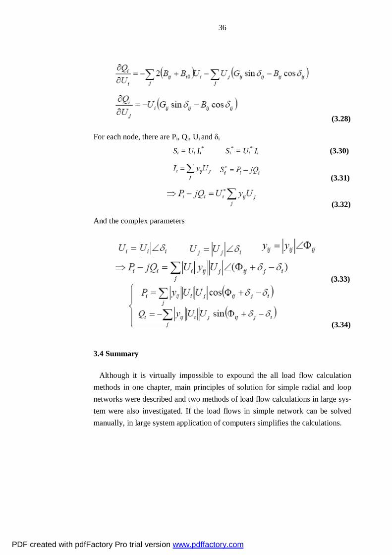
(3.28)
For each node, there are Pi, Qi, Ui and δi
Si = Ui Ii∗ ⇒ Si
∗ = Ui∗ Ii (3.30)
(3.31)
(3.32)
And the complex parameters
(3.33)
(3.34)
3.4 Summary
Although it is virtually impossible to expound the all load flow calculation methods in one chapter, main principles of solution for simple radial and loop networks were described and two methods of load flow calculations in large sys-tem were also investigated. If the load flows in simple network can be solved manually, in large system application of computers simplifies the calculations.
PDF created with pdfFactory Pro trial version www.pdffactory.com

37
4 Case study calculations
The main aim of these case study calculations is to visually analyse and show
the essence of processes occurring in three phase radial distribution system. Also
we will try to summarise and, where it is needed, to apply the information from
the previous chapters. I will examine three-phase network, when one or two
phases overloaded or underloaded. The connection on distribution transformer
also will be changed. First study will be with delta-star connection with zero
conductor. The next case is when the zero conductor is broken out. The third
case will be delta-zigzag connection on the transformer`s secondary. This con-
nection is used in order to minimise the impact of unsymmetry, so we will exam-
ine how much it is justified. The study will be conducted by method of symmet-
rical components for unsymmetrical situation. Also for first case I will make
comparative calculations by method of neutral displacement.
4.1 introduction to the calculations
As it said before, the calculations are conducted in order to examine the im-
pact of unsymmetrical loads on one or two phases on the currents and voltages in
the rest. Also I will examine the impact of the zero conductor on this unsym-
metry. The third case calculation is conducted to find out how the zigzag connec-
tion on the transformer’s secondary reduce this unsymmetry.
At the beginning we should find the impedances of all components of the
network. For the transformer the resistance on the secondary is equal to
2
k kn
UR rS
= ⋅
(4.1)
Where rk is short circuit resistance of the transformer. U is the rated voltage in
the transformer’s secondary and Sn is total power of the transformer.
The reactance of the transformer on the secondary is equal to
2
k kn
UX xS
= ⋅
(4.2)
PDF created with pdfFactory Pro trial version www.pdffactory.com
38
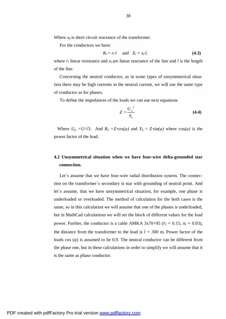
Where xk is short circuit reactance of the transformer.
For the conductors we have:
Rl = rl·l and Xl = xl·l. (4.3)
where rl linear resistance and xl are linear reactance of the line and l is the length
of the line.
Concerning the neutral conductor, as in some types of unsymmetrical situa-
tion there may be high currents in the neutral current, we will use the same type
of conductor as for phases.
To define the impedances of the loads we can use next equations
2
p
n
UZ
S=
(4.4)
Where Up =U/√3. And RL =Z·cos(φ) and XL = Z·sin(φ) where cos(φ) is the
power factor of the load.
4.2 Unsymmetrical situation when we have four-wire delta-grounded star
connection.
Let`s assume that we have four-wire radial distribution system. The connec-
tion on the transformer`s secondary is star with grounding of neutral point. And
let`s assume, that we have unsymmetrical situation, for example, one phase is
underloaded or overloaded. The method of calculation for the both cases is the
same, so in this calculation we will assume that one of the phases is underloaded,
but in MathCad calculations we will set the block of different values for the load
power. Further, the conductor is a cable AMKA 3x70+95 (rl = 0.15, xl = 0.03),
the distance from the transformer to the load is l = 300 m. Power factor of the
loads cos (φ) is assumed to be 0,9. The neutral conductor can be different from
the phase one, but in these calculations in order to simplify we will assume that it
is the same as phase conductor.
PDF created with pdfFactory Pro trial version www.pdffactory.com
39
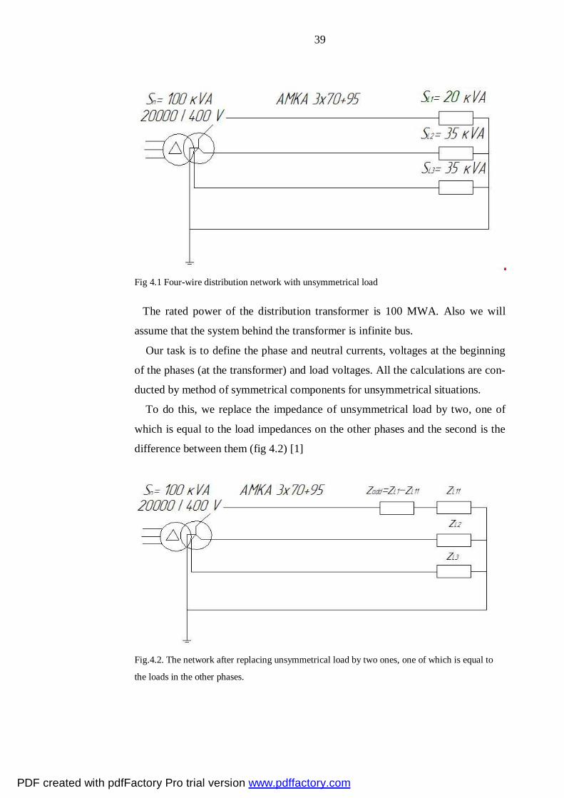
Fig 4.1 Four-wire distribution network with unsymmetrical load
The rated power of the distribution transformer is 100 MWA. Also we will
assume that the system behind the transformer is infinite bus.
Our task is to define the phase and neutral currents, voltages at the beginning
of the phases (at the transformer) and load voltages. All the calculations are con-
ducted by method of symmetrical components for unsymmetrical situations.
To do this, we replace the impedance of unsymmetrical load by two, one of
which is equal to the load impedances on the other phases and the second is the
difference between them (fig 4.2) [1]
Fig.4.2. The network after replacing unsymmetrical load by two ones, one of which is equal to
the loads in the other phases.
PDF created with pdfFactory Pro trial version www.pdffactory.com
40
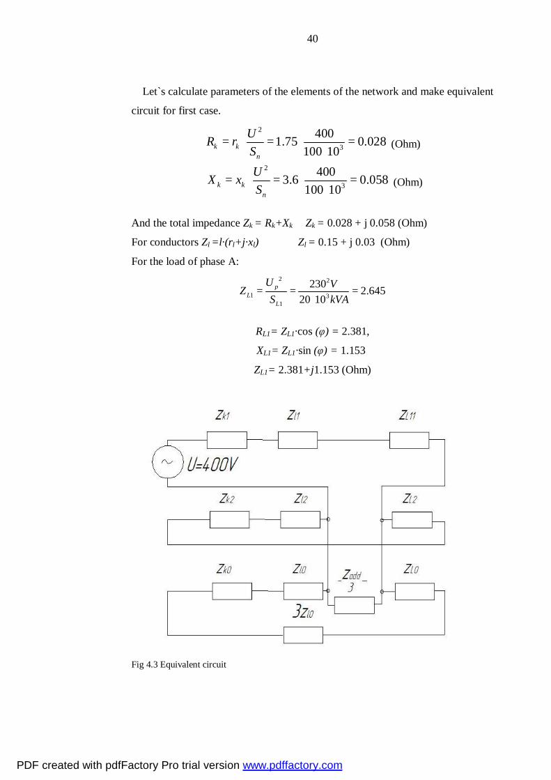
Let`s calculate parameters of the elements of the network and make equivalent
circuit for first case. 2
3
4001.75 0.028100 10k k
n
UR rS
= ⋅ = ⋅ =⋅
(Ohm)
2
3
4003.6 0.058100 10k k
n
UX xS
= ⋅ = ⋅ =⋅
(Ohm)
And the total impedance Zk = Rk+Xk Zk = 0.028 + j 0.058 (Ohm)
For conductors Zl =l·(rl+j·xl) Zl = 0.15 + j 0.03 (Ohm)
For the load of phase A: 2 2
1 31
230 2.64520 10
pL
L
U VZS kVA
= = =⋅
RL1= ZL1·cos (φ) = 2.381,
XL1= ZL1·sin (φ) = 1.153
ZL1= 2.381+j1.153 (Ohm)
Fig 4.3 Equivalent circuit
PDF created with pdfFactory Pro trial version www.pdffactory.com

41
For the loads of phases B and C
2 2
31
230 1,51135 10
pL
L
U VZS kVA
= = =⋅
RL = ZL·cos (φ) = 1.36
XL = ZL sin (φ) = 0.659
ZL= 1.36+ j0.659 (Ohm)
Now we should determine the additional impedance
Zadd = ZL1 –ZL11 = 2.381+ j·1.15 – 1.36 + j·0.659 (Ohm)
Zadd = 1.02+ j·0.494 (Ohm)
Let`s find impedances of each sequence and after that the equivalent imped-
ance of the circuit respectively to the place of unsymmetry for the special phase
(A).
The positive-sequence impedance is equal to the sum of impedances of each
element of the network:
Z1 = Zk1 + Zl1 + ZL11 (4.5)
The negative sequence is frequently the same as positive
Z2 = Zk2 + Zl2 + ZL2 (4.6)
For zero-sequence impedance we have some differences. For transformers the
value of zero-sequence impedance depends on the way of connection of the
windings and embodiment. For connection delta- star with grounding, we can
assume that it is equal to the positive-sequence impedance. For the cable we can
assume that Z0l = 3.5· Z1l , and for load we will assume the impedance to be the
same as for positive and negative-sequences. The zero-sequence impedance of
the zero conductor is tripled because currents of all three phases flow through
this conductor. Thus
Z0 = Zk0 + 3.5Zl0 + ZL0 + 3Zl0 (4.7)
So, the equivalent impedance
PDF created with pdfFactory Pro trial version www.pdffactory.com

42
2
02
2
02
33
3
33
3
add
add
eqvadd
add
Z Z
ZZ Z
Z Z Z
ZZ Z
⋅
⋅+ ⋅
=⋅
++ ⋅
(4.8)
And now the positive-sequence current can be calculated from the equation [2],
1
1
f
eqv
jUI
Z Z=
+
(4.9)
where Uf =U/√3 . The negative-sequence current is equal to
2 1
2
eqvZI I
Z= −
(4.10)
And zero-sequence current
0 1
0
eqvZI I
Z= −
(4.11)
And knowing the symmetrical components we can calculate the phase values
of the currents and respectively voltages.
Ia = I0 + I1 + I2
Ib = I0 + a2 I1 + a I2 (4.12)
Ic = I0 + a I1 + a2 I2
The current in the zero conductor equals to the sum of the phase currents:
Iz = Ia + Ib + Ic (4.13)
And the phase voltages are equal to the multiplication of the phase imped-
ances to respective phase currents
Ua = Ia (Zk1 + Zl1 + ZL1)
Ub = Ib (Zk2 + Zl2 + ZL2) (4.14)
Uc = Ic (Zk2 + Zl2 + ZL3)
PDF created with pdfFactory Pro trial version www.pdffactory.com

43
And the voltages at the loads
UL1 = Ia·ZL1
UL2 = Ib·ZL2 (4.15)
UL3 = Ic·ZL3
By substituting our values for transformer, line and load impedances, we get
Z1 = 1.538 + j0.747 (Ohm)
Z2 = 1.538 + j0.747 (Ohm)
Z0 = 2.453 + j0.822 (Ohm)
Zeqv = 0.251 + j 0.117 (Ohm)
And the symmetrical components of the currents
I1 = 50.561+ j 104.679 , I2 = -8.422 - j16.814, I0 = -4.094 – j 11.736i
And the phase currents
Ia = 38.044 + j 76.129 (A)
Ib = 80.086 – j 106.983 (A)
Ic = -130.483 – j 4.501 (A)
Iz = -12.353 - j 35.355 (A)
The root-mean-square meanings of these currents
IA = 84.868 A IB = 133.638 A IC = 130.561 A IZ = 37.451 A
The phase voltages
Ua = 2.793 + j 225.086 UA = 242.002 V
Ub = 203.092- j 104.761 UB = 228.519 V
Uc = -197.359 - j104.371 UC = 223.257 V
The voltages at the loads
UL1 = 2.793 + j 225.086 UL1m = 225.103 V
UL2 = 179.422 – j 92.765 UL2m = 201.984 V
UL3 = - 174.529- j 92.087 UL3m = 197.333 V
PDF created with pdfFactory Pro trial version www.pdffactory.com

44
The current unbalance factor of the negative sequence is defined as
22
1I
Ik
I= k2I = 0.162 = 16.2 % (4.16)
The current unbalance factor of the zero-sequence is equal
00
1
| | 0.107 10.7%| |IIkI
= = = (4.17)
Now we will make the comparative calculation for the same situation but this
time with the method of neutral displacement. As we know, under unsymmetric-
al situation, the neutral point of the three phases can shift. We should calculate
the displacement voltage (Un0), after which we will be able to define the load
voltages and consequently, the currents flowing in the phases.
0
0
1 1 1 1
a b c
a b cn
a b c l
U U UZ Z ZU
Z Z Z Z
+ +=
+ + + (4.18)
Where
Za = Zk1 + Zl1 + ZL1,
Zb= Zk2 + Zl2 + ZL2, (4.19)
Zc= Zk2 + Zl2 + ZL3
And Ua = U, Ub = a2U, Uc = a·U
In our case we get the voltages at the phases
UAn = Ua – Un0
UBn = Ub – Un0 (4.20)
UCn = Uc – Un0
And the phase currents
Ana
a
UIZ
= , Bnb
b
UIZ
= , Cnc
c
UIZ
= , 00
0
nUIZ
=
(4.21)
PDF created with pdfFactory Pro trial version www.pdffactory.com

45
From the above equations we get
Un0 = - 6.546 + j 1.381 | Un0 | = 6.69 V
UAn= 236.546 - j1.381 | UAn| = 236.55 V
UBn = -108.454 - j 200.566 | UBn| = 228.011 V
UCn = -108.454 + j 197.805 | UCn| = 225.586 V
For the currents
Ian = 74.625- j 36.72 |Ian| = 83.174 A
Ibn = -108.305 - j 77.804 |Ibn| = 133.355 A
Icn = -6.513 + j 131.775 |Icn| = 131.936 A
And the current in the zero conductor
In0 = - 40.193 + j 17.242 | In0| = 43.736 A
If to compare the results of two methods of calculation, we can see that the
calculating error does not exceed 5%. The biggest difference has phase a: for
current it is 2% and for voltage 2.3%
84.868 83.174100% 100% 2%84.868
a an
a
I II− −
⋅ = ⋅ =
(4.22)
242 236.55100% 100% 2.3%242
a An
a
U UU− −
⋅ = ⋅ =
(4.23)
The error can be result both of calculating inaccuracy and the assignment of
initial data. For example, the zero-sequence impedance for cables of different
types can mainly vary from 2.5 to 4.5. As well as zero-sequence impedance of
loads can be different depending on the character of the load. But in the ranges
of the given task, I consider that the received results are satisfying.
In order to check the equations for symmetrical components, I took three
different values of load power for special phase (phase a in my case). The results
for the first case (when the power of the phase a is less than the powers of the
other two phases) I brought above. In this case the voltage at the phase a is high-
er than the voltages at the other two phases and current is lower.
PDF created with pdfFactory Pro trial version www.pdffactory.com

46
The second case when the power of phase a is the same as for the phases b and
c. This case we have symmetrical situation and as expected we have only posi-
tive component and the negative and zero components are equal to zero. The
main result of symmetrical loads, that there is no voltage displacement and no
current in the zero conductor.
The third case is when the load of one phase is more than the loads of the rest.
In this case we have the opposite situation than in the first case. The current is
higher than in the other two phases and the voltage is lower. Also in this case we
have current in the zero conductor. For both first and third cases the voltage at
the underloaded phases can be higher than the nominal phase voltage.
There are two vector diagrams below for the situation, when all three loads
are equal (that is, balanced loads) and for the above described unsymmetrical
situation.
Fig 4.4. The vector diagram of voltages and currents in the balanced situation
PDF created with pdfFactory Pro trial version www.pdffactory.com

47
From the first diagram we can see, that the neural point of voltages and cur-rents corresponds to zero. The distribution of the vectors is symmetrical and the angle between phases is 120o. And as follows from the second figure, the neutral point is shifted to the left and there appears zero conductor current which bal-ances the current difference in the phases.
Fig 4.5. The vector diagram of voltages and currents in the unbalanced situation
4.3 Unbalanced situation with the broken zero conductor
In the four-wire network the neutral conductor required when we have un-
symmetrical situation. In this case the sum of the phase current flow through it.
Ia + Ib + Ic = I0 (4.25)
Let`s have a look to what it brings about. In this case we have the network
shown in the figure 5.6. When the neutral conductor is broken or when we have
PDF created with pdfFactory Pro trial version www.pdffactory.com

48
three-wire network under unbalanced loads, there is no way to zero-consequence
currents. In this case we have only positive-sequence and negative-sequence
components of the current and voltage.
Fig.4.6. Unbalanced situation when neutral conductor is broken.
In this case we also replace the impedance of the unsymmetrical load by, one
of which is equal to the impedances of the loads in other two phases.
But now, because we do not have path for zero-sequence current, the equiva-
lent circuit will look in other way.
Fig.4.7. the equivalent circuit when there is no way for zero-sequence currents
PDF created with pdfFactory Pro trial version www.pdffactory.com

49
The positive-sequence impedance is equal, as before, to the sum of imped-
ances of each element of the network:
Z1 = Zk1 + Zl1 + ZL11 The negative sequence is also the same as positive
Z2 = Zk2 + Zl2 + ZL2
In this case the equivalent impedance
2
2
33
3
add
eqvadd
Z Z
Z Z Z
⋅
=+ ⋅
(4.26)
And now the positive-sequence and negative-sequence components of the cur-rent can be calculated from the equations,
11
P
eqv
jUI
Z Z=
+
2 12
eqvZI I
Z= −
Where Up =U/√3. In case of absence of zero-sequence, the equations for calculating phase cur-
rents look in next way
Ia = I1 + I2
Ib = a2 I1 + a I2
Ic = a I1 + a2 I2
For the phase voltages we get
Ua = Ia Za
Ub = Ib Zb
Uc = Ic Zc
And the voltages at the loads
UL1 = Ia·ZL1
UL2 = Ib·ZL2
UL3 = Ic·ZL3
By substituting the numerical data we get
Z1 = 1.538 + j0.747 (Ohm)
Z2 = 1.538 + j0.747 (Ohm)
PDF created with pdfFactory Pro trial version www.pdffactory.com
50
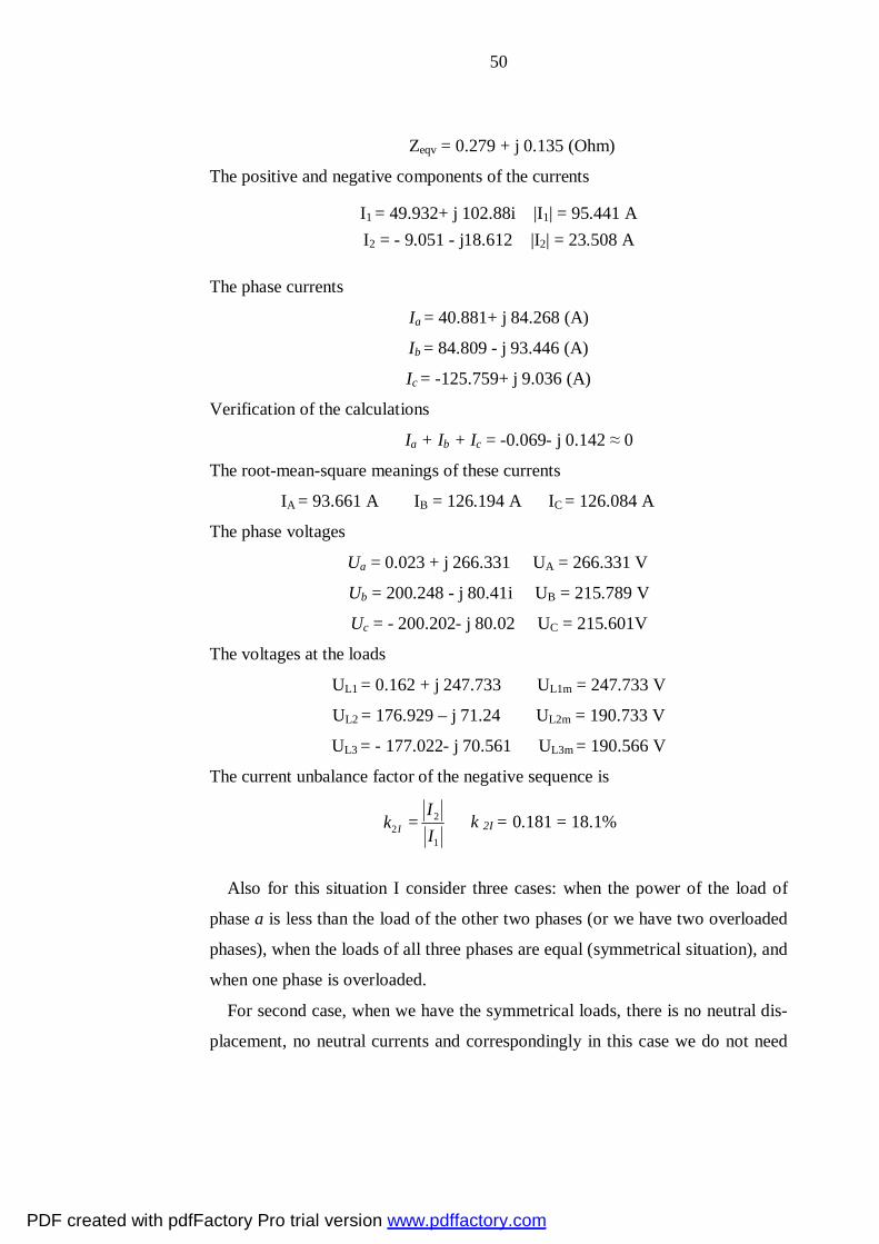
Zeqv = 0.279 + j 0.135 (Ohm)
The positive and negative components of the currents
I1 = 49.932+ j 102.88i |I1| = 95.441 A I2 = - 9.051 - j18.612 |I2| = 23.508 A
The phase currents
Ia = 40.881+ j 84.268 (A)
Ib = 84.809 - j 93.446 (A)
Ic = -125.759+ j 9.036 (A)
Verification of the calculations
Ia + Ib + Ic = -0.069- j 0.142 ≈ 0
The root-mean-square meanings of these currents
IA = 93.661 A IB = 126.194 A IC = 126.084 A
The phase voltages
Ua = 0.023 + j 266.331 UA = 266.331 V
Ub = 200.248 - j 80.41i UB = 215.789 V
Uc = - 200.202- j 80.02 UC = 215.601V
The voltages at the loads
UL1 = 0.162 + j 247.733 UL1m = 247.733 V
UL2 = 176.929 – j 71.24 UL2m = 190.733 V
UL3 = - 177.022- j 70.561 UL3m = 190.566 V
The current unbalance factor of the negative sequence is
22
1I
Ik
I= k 2I = 0.181 = 18.1%
Also for this situation I consider three cases: when the power of the load of
phase a is less than the load of the other two phases (or we have two overloaded
phases), when the loads of all three phases are equal (symmetrical situation), and
when one phase is overloaded.
For second case, when we have the symmetrical loads, there is no neutral dis-
placement, no neutral currents and correspondingly in this case we do not need
PDF created with pdfFactory Pro trial version www.pdffactory.com

51
the neutral conductor. In ideal, the need in neutral conductor is always tried to be
as less as possible.
In case when we have one underloaded (two overloaded) or overloaded phases
the situation is radically different. The voltage of overloaded phases much lower
than the voltages of other phase(s), and at the same time the voltage(s) of under-
loaded phase(s), depending on the situation, can be higher than the nominal vol-
tage of the transformer’s secondary.
Below I brought vector diagrams for the first and third cases. From these fig-
ures and from the previous calculations one can see that in case when phase a is
underloaded, we have neutral displacement to the left and the vector designating
the current of phase a is shorter than the others, when in third case vice versa.
Fig.4.8 The vector diagram of voltages and currents in the unbalanced situation with the broken
neutral conductor (underloaded phase a).
If to compare the result for the same unsymmetrical situation with neutral conductor and without it, we can see that in second case this has bigger conse-quences on the phase values of the voltages and currents.
PDF created with pdfFactory Pro trial version www.pdffactory.com

52
Fig.4.9 The vector diagram of voltages and currents in the unbalanced situation with the broken
neutral conductor (overloaded phase a).
The comparative values for these two cases are given below in table 4.1. Table 4.1. Phase values of voltages and current with neutral conductor and without
With neutral Without neutral Abs. difference Rel. difference Ia, A 84.868 93.661 -8.79 10.3% Ib, A 133.638 126.194 7.44 5.5% Ic,A 130.561 126.084 4.48 3.4% Ua,V 242.002 266.331 -24.33 10% Ub,V 228.519 215.789 12.73 5.5% Uc,V 223.257 215.601 7.65 3.4%
One can notice that in case of absence of neutral conductor the unsymmetry is
bigger, especially for voltages. In case with neutral conductor the difference in
the currents` value in the overloaded and normal phases are higher than in case
PDF created with pdfFactory Pro trial version www.pdffactory.com

53
with broken zero conductor but the difference between phase voltage values
smaller than in case with no zero conductor.
4.4 Unbalanced situation when supplying via zig-zag transformer
The zero-sequence impedance of the zig-zag transformer is very law as com-
pared with positive-sequence and negative-sequence impedances. Positive and
negative-sequence impedances are approximately two times as much as imped-
ances of respective transformer with connection ∆/YGRD. Also the zero sequence
currents flowing through zig-zag transformer`s coils, creates magnetizing forces
which are directed opposite to each other. It eliminates the impact of zero se-
quence currents.
Taking into account all above mentioned, for the phase voltages were got fol-
lowig values
Ua = 210.945 + j106.512 UA = 236.31 V
Ub = 205.125 + j 106.351 UB = 231.056 V
Uc = 200.727 + j 104.071 UC = 226.102V
The root-mean-square meanings of these currents
IA = 82 A IB = 132.144 A IC = 129.131 A
A zigzag connection may be useful when a neutral is needed for grounding or
for supplying single-phase line to neutral loads when working with a 3-wire,
ungrounded power system. Due to its composition, a zigzag transformer is more
effective for grounding purposes because it has less internal winding impedance
going to the ground than when using a wye-type transformer.
It is not efficient to use zigzag configurations for typical industrial or
commercial loads, because they are more expensive to construct than
conventional wye-connected transformers. But zigzag connections are useful in
special applications where conventional transformer connections aren't effective
PDF created with pdfFactory Pro trial version www.pdffactory.com
54
5 Analysis of impact of unsymmetrical loads (depending on
vector group of mv/lv transformer) and quality of voltage
As we could see from case study calculations, the vector group of supplying
transformer inpacts to the value of the inbalance. In this chapter different types
of connection of transformers primary and secondary and respectively,
advantages and disadvantages of such connections in distribution networks will
be discribed.
As well as we will analyze the physical processes occuring in the windings of the
transformers that bring about to leveling the unbalance or, on the contrary, to its
strengthening.
Also at the end of the thesis the voltage quality issues are investigated and
the consequences of voltage distortion and higher voltage drop are described.
5.1 Transformers and their role in distribution systems
The transformer that connects the high voltage primary system (4.16kV to
34.5 kV) to the customer (at 480 volts and below) is usually referred to as a “dis-
tribution transformer”. These transformers can be either single-phase or three-
phase and range in size from about 5 kVA to 500 kVA [10( power distribution
engineering]. With given secondary voltage, distribution transformer is usually
the last in the chain of electrical energy supply to households and industrial en-
terprises.
There are 3 main parts in the distribution transformer:
1. Coils/winding – where incoming alternate current (through primary winding)
generates magnetic flux, which in turn develop a magnetic field feeding back a
secondary winding.
2. Magnetic core – allowing transfer of magnetic field generated by primary
winding to secondary winding by principle of magnetic induction.
First 2 parts are known as active parts.
PDF created with pdfFactory Pro trial version www.pdffactory.com

55
3. Tank – serving as a mechanical package to protect active parts, as a holding
vessel for transformer oil used for cooling and insulation and bushing (plus aux-
iliary equipment where applicable)
Fig 5.1. Schematic view of the single-phase distribution transformer
Distribution Transformers are usually fulfilled from copper or aluminum
conductors and are wound around a magnetic core to transform current from one
voltage to another. Distribution transformers come in two types- dry-type and
liquid. The Dry Type Distribution Transformers are usually smaller and do not
generate much heat and can be located in a confined space at a customer's
location. The liquid type usually have oil which surrounds the transformer core
and conductors to cool and electrically insulate the transformer (see also Oil
Filled Transformers). The liquid distribution transformer types are usually the
larger and need more than air to keep them from overheating thus in this type of
transformers oil insulator is often used.
The winding connections of the transformers depend on the character of load
supplying by them and usually wye-delta, delta-wye, delta-delta or wye-wye
(wye can be grounded).
In table 5.1 there shown some of the standard kVAs and voltages for
distribution transformers. [4]
PDF created with pdfFactory Pro trial version www.pdffactory.com

56
Table 5.1 Standard distribution transformer kVAs and voltages
kVAs High voltages Low voltages
Single-
phase
Three-
phase
Single-phase Three-phase Single-
phase
Three-phase
5
10
15
25
37.5
50
75
100
167
250
333
500
30
45
75
112.5
150
225
300
500
2400/4160Y
4800/8320Y
2400/4160Y
4800/8320YX
7200/12,470Y
12470YGRD/7200
7620/13200Y
13200YGRD/7620
12000
13200/22860YGRD
13200
13800/23900YGRD
13800
14400/24940YGRD
22900
34400
43800
67000
2400
4160Y/2400
4160Y
4800
8320Y/4800
8320Y
7200
12000
12470Y/7200
12470Y
13200/7620
13200Y
13200
13800
22900
34400
43800
67000
120/240
240/480
2400
2520
4800
5040
6900
7200
7560
7980
208Y/120
240
480Y/277
240X480
2400
4160Y/2400
4800
12470Y/7200
13200Y/7620
5.2 Analysis of impact of unsymmetrical loads depending on vector group
of mv/lv transformers.
A vector group determines the phase angle displacement between the primary
(HV) and secondary (LV) windings..
PDF created with pdfFactory Pro trial version www.pdffactory.com

57
The phase windings of a three-phase transformer can be connected together
internally in different configurations, depending on what characteristics are
needed from the transformer. For example, in a three-phase distribution system,
it may be necessary to connect a three-wire system to a four-wire system, or vice
versa. Because of this, transformers are manufactured with a variety of winding
configurations to meet these requirements.
Different combinations of winding connections will result in different phase
angles between the voltages on the windings. This limits the types of transfor-
mers that can be connected between two systems, because mismatching phase
angles can result in circulating current and other system disturbances.
Transformer nameplates carry a vector group reference such at Yy0, Yd1,
Dyn11 etc. This relatively simple nomenclature provides important information
about the way in which three phase windings are connected and any phase dis-
placement that occurs
Winding Connections
HV windings are designated: Y, D or Z (upper case)
LV windings are designated: y, d or z (lower case)
Where:
Y or y indicates a star connection
D or d indicates a delta connection
Z or z indicates a zigzag connection
N or n indicates that the neutral point is brought out
Phase Displacement
The digits (0, 1, 11 etc) relate to the phase displacement between the HV and LV
windings using a clock face notation. The phasor representing the HV winding
is taken as reference and set at 12 o'clock. It then follows that:
PDF created with pdfFactory Pro trial version www.pdffactory.com
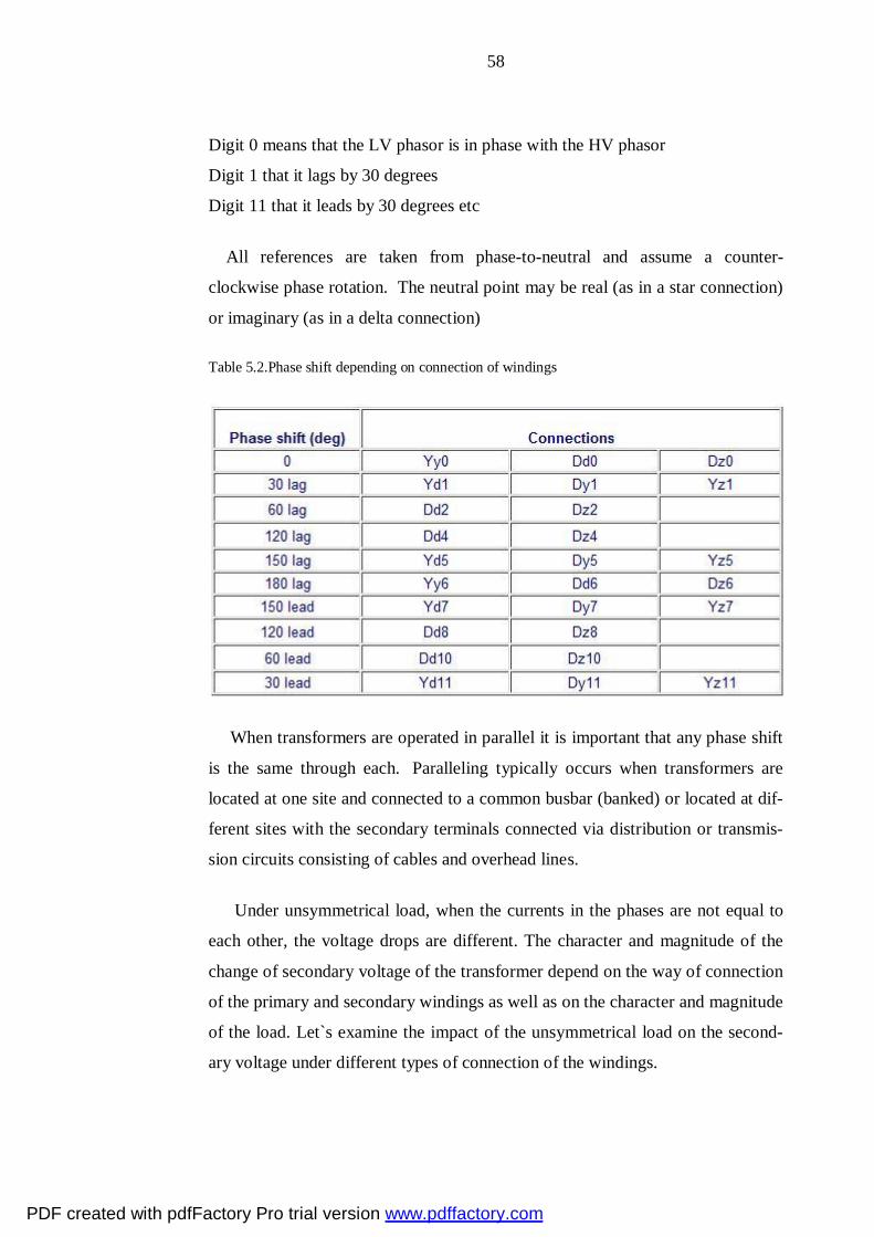
58
Digit 0 means that the LV phasor is in phase with the HV phasor
Digit 1 that it lags by 30 degrees
Digit 11 that it leads by 30 degrees etc
All references are taken from phase-to-neutral and assume a counter-
clockwise phase rotation. The neutral point may be real (as in a star connection)
or imaginary (as in a delta connection)
Table 5.2.Phase shift depending on connection of windings
When transformers are operated in parallel it is important that any phase shift
is the same through each. Paralleling typically occurs when transformers are
located at one site and connected to a common busbar (banked) or located at dif-
ferent sites with the secondary terminals connected via distribution or transmis-
sion circuits consisting of cables and overhead lines.
Under unsymmetrical load, when the currents in the phases are not equal to
each other, the voltage drops are different. The character and magnitude of the
change of secondary voltage of the transformer depend on the way of connection
of the primary and secondary windings as well as on the character and magnitude
of the load. Let`s examine the impact of the unsymmetrical load on the second-
ary voltage under different types of connection of the windings.
PDF created with pdfFactory Pro trial version www.pdffactory.com

59
Delta-delta connection
Let`s assume that the load is included between two terminals a and b (Fig 5.2).
As the phase ab is included parallel to two tandem phases ac and ba, than when
the total impedances of windings of all three phases are equal and magnetizing
component is insignificant, distribution of the load current I2` to all phases of
primary and secondary windings will meet the figure 5.2. that is, in phase ab the
current is equal to 2/3 I2`, where I2` is load current, and the current in phases ac
and cb will be equal to 1/3 I2`, as impedance of two series connected phases ac
and cb is twice as much as the impedance of phase ab [3].
Fig.5.2. Unbalance under ∆/∆ connection.
The currents in the secondary will be balanced by the currents in the primary,
which means that in the primary phases the current will be distributed exactly as
in the secondary phases, that is in the phase AB it will be equal to 2/3 I1, where I1
is the line current flowing to the node A, and in the phases AC and CB it will be
equal to 1/3 I1. The directions of the currents are such that in the line coming
to the node C there is no current. Consequently, the potential of the terminal C
will not change under load. That is, the point C of the potential diagram will stay
at the same place where it was, when the potentials of the terminals a and b will
shift to the same direction with respect to the position under no-load operation.
In the figure 5.3 there shown the potential diagram assuming that the second-
ary current is corresponding in phase with primary voltage between terminals
AB. In this picture triangle ABC is potential triangle of primary voltages and abc
is potential triangle of secondary voltages under load.
PDF created with pdfFactory Pro trial version www.pdffactory.com

60
Fig.5.3. Potential triangles under unsymmetrical load
From this figure we can see that under unsymmetrical load, which is under
consideration, the voltages of the loaded and one of the adjacent phases decrease,
and the voltage of the other adjacent phase increases.
Star-star and delta-star connections
As in previous example, let`s assume that the load is included between two
conductors of the secondary. In this case the current will flow only in the phases,
adjacent to these conductors, and consequently in the conductors of the primary,
conjugated to the mentioned. Thus, the current in the phase oc of the secondary
will be equal to zero, and in the phase OC of the primary will flow only magne-
tizing current.
By replacing the star-connection by delta-connection, one will get the identical
system, which we examined before.
Fig.5.4. Unbalance under star-star connection
PDF created with pdfFactory Pro trial version www.pdffactory.com

61
Therefore, the construction of the points, responding to the potentials of ter-
minals a and b under load will not differ from drawn in the figure 5.3.
The phase voltages in this case are not equal either. Voltage of one loaded
phase is higher, and the voltage of the second phase is less than the voltage of
third loaded phase.
For the delta-star connection, all the same and the above-mentioned processes
take place.
Zig-zag transformer
The secondary winding of each phase of zig-zag transformer consists of two
coils. One coil is located on one core and the second one on the second core, and
the end of the first coil, for example, x1, is connected to the end of the second
coil, for example, y2.
Thus, the zigzag transformer contains six coils on three cores. The first coil
on each core is connected contrariwise to the second coil on the next core. The
second coils are then all tied together to form the neutral and the phases are con-
nected to the primary coils. Each phase, therefore, couples with each other phase
and the voltages cancel out. As such, there would be negligible current through
the neutral pole and it can be tied to ground.
Fig. 5.5. Zig-zag transformer
PDF created with pdfFactory Pro trial version www.pdffactory.com

62
If one phase, or more, faults to earth, the voltage applied to each phase of the
transformer is no longer in balance; fluxes in the windings no longer oppose.
Zero sequence (earth fault) current exists between the transformer’s neutral to
the faulting phase. Hence, the purpose of a zigzag transformer is to provide a
return path for earth faults on delta-connected systems. With negligible current
in the neutral under normal conditions, engineers typically elect to under size the
transformer; a short time rating is applied (i.e., the transformer can only carry
full rated current for, say, 60 s).
Fig.5.6. Vector diagram of zig-zag transformer.
When the coils of the transformer are connected in zig-zag, the vector diagram
will look like in the figure 5.6. From this figure we can see, that the phase vol-
tages U1, U2, U3, will be equal to the geometrical sum of the voltages of the re-
spective coils, and
U1 = U2 = U3 = √3 e1 = √3 e2 (5.1)
In consequence of location of the secondary winding on two cores, unsymme-
trical load lies on all phases in more or less equal degree reducing the phase vol-
tage difference. Also, as it said in chapter 4, the effect of elimination of the mag-
netazing forces by zero sequence currents occur, which reduce the impact of the
unsymmetrical situation
PDF created with pdfFactory Pro trial version www.pdffactory.com

63
5.3 The quality of voltage and its impact on consumers
Defined in terms of magnitude (amplitude) and duration (length), voltage
events - appearing in the form of sags, swells, impulses, and total harmonic dis-
tortion - can affect equipment performance in different ways. Typically, the ul-
timate impact of such events is determined by the sensitivity of the equipment on
the branch circuit.
• Voltage sags
A sag is a period of low voltage. Minor sags occur frequently, sometimes
without disturbing equipment performance. Major sags, on the other
hand, always disturb equipment performance. Sags occur for many rea-
sons, including voltage drop caused by long runs of wire, switching
loads, poor wiring, and overloaded branch circuits.
• Voltage swells
A swell is a period of high voltage. Swells have serious impact on
equipment function; however, they are not as common as sags. Both
minor and major swells affect equipment performance.
• Impulses
An impulse is a short burst of energy that lasts for less than a cycle. Im-
pulses range in magnitude from twice the nominal voltage to several
thousand volts. Not every impulse has an impact on equipment perfor-
mance. However, when impulses occur repeatedly over time (or when the
energy level is very high), an impulse can cause equipment degradation
or even immediate failure.
• Harmonics
AC voltage is a sine wave that repeats 50/60 times per second (Hertz =
cycles/second). This is the fundamental frequency. Harmonics are alter-
nate frequencies that distort the sinusoidal waveform. Total harmonic dis-
tortion (THD) is measured as a percentage of the fundamental frequency.
PDF created with pdfFactory Pro trial version www.pdffactory.com

64
Equipment runs well on voltage that is a clean (or slightly distorted) sine
wave. High levels of distortion may cause equipment problems. On sin-
gle-phase branch circuits, levels of THD greater than 5% to 8% should be
investigated.
5.4 Effects of voltage distortion.
Electrical equipment is designed to work at nominal voltage (+/-10%). Al-
though equipment may not fail the first time an event occurs, excessive stress
from repeated voltage events can cause damage over time. When voltage is out-
side of equipment design specifications, for example, equipment has to work
harder, run hotter, or insulation may have to withstand extreme voltage levels.
For instance, a refrigerator is designed to operate between 108VAC and
132VAC - that is, a typical voltage range for a nominal 120V piece of equip-
ment. If voltage runs consistently below 108V on the circuit powering the refri-
gerator, the compressor motor will run hotter, reducing its operation and service
life.
Sags are the most prevalent power quality issue for equipment. Momentary
sags may not affect the refrigerator referenced above, but they will cause prob-
lems for more sensitive equipment, such as computers. The greater the voltage
sag, the greater the likelihood of damage. Similarly, the greater the number of
sags occurring, the greater the chance of failure or damage.
Although voltage swells occur less frequently than sags, even relatively minor
swells can damage equipment. Therefore, they require immediate attention. The
longer a swell's duration, the more extensive the damage will be. An example
here would be a large motor creating voltage sags by drawing high inrush cur-
rents. When the motor is stopped abruptly, voltage swells are generated. Left
uncorrected, these sags and swells will lead to computer disruptions and frequent
hardware replacement in the facility.
PDF created with pdfFactory Pro trial version www.pdffactory.com

65
THD can produce excessive heat, generate electro-magnetic interference in
communications circuits, and cause electronic controls to fail. Non-linear loads,
such as PCs, copying machines, and variable-frequency drives, create harmonic
currents that distort the voltage sine wave. The more electronic devices on a cir-
cuit, the greater the likelihood of severe voltage distortion. A good example of
such a problem involved a hospital technician who tested a circuit for two days
before installing patient monitoring equipment. One instance of voltage harmon-
ics, amounting to 5.2% THD, was noted. Recognizing this low level of THD
wouldn't cause a problem, the technician installed the patient monitoring device.
Within hours, the device failed. The technician reviewed new data to find a THD
event reaching 10.2%. Further investigation using a circuit analyzer and long-
term recorders found there were several non-linear loads plugged into the same
branch circuit as the patient monitoring device. When certain combinations of
these loads were on simultaneously — along with the new equipment — exces-
sive harmonics flowed, causing a distorted voltage waveform and sporadic shut-
down of the device.
Besides overheating, the other major effect of current distortion on an elec-
trical system is the creation of voltage distortion. This distortion will have mini-
mal effect on a distribution system, but unlike current distortion, it isn't path de-
pendent. So harmonic voltages generated in one part of a facility will appear on
common buses within that facility. High-voltage distortion at the terminals of a
nonlinear load doesn't mean high distortion will be present throughout the sys-
tem. In fact, the voltage distortion becomes lower the closer a bus is located to
the service transformer. However, if excessive voltage distortion does exist at the
transformer, it can pass through the unit and appear in facilities distant from the
origin.
The effect on loads within the facility could be detrimental in certain cases.
For example, extreme voltage distortion can cause multiple zero crossings for the
voltage wave. For equipment where proper sequencing of operations depends on
a zero crossing for timing, voltage distortion can cause misoperation. Most mod-
PDF created with pdfFactory Pro trial version www.pdffactory.com

66
ern electrical equipment uses an internal clock for timing sequencing so it's unaf-
fected by multiple zero crossings.
Voltage distortion appears to have little effect on operation of nonlinear loads
connected either phase-to-phase or phase-to-neutral.
On the other hand, 5th harmonic voltage distortion can cause serious prob-
lems for 3-phase motors. The 5th harmonic is a negative sequence harmonic, and
when supplied to an induction motor it produces a negative torque. In other
words, it attempts to drive the motor in a reverse direction and slows down its
rotation. So the motor draws more 60-Hz current to offset the reverse torque and
regain its normal operating speed. The result is overcurrent in the motor, which
either causes protective devices to open or the motor to overheat and fail. For
this reason, removing 5th harmonic current from systems powering 3-phase
loads is often a high priority in industrial facilities.
System harmonic voltage distortion is caused by the flow of harmonic cur-
rents through system impedance, namely inductive reactance. For each fre-
quency, at which harmonic current is flowing, there is a corresponding inductive
reactance associated with system and thus a voltage drop at that frequency. The
factors that affect the system inductive reactance are the generator, transformer,
series line reactors or current limiting reactors, and circuit conductors. Fig. 1
When the load current consists of fundamental current and 5th harmonic current,
there will be a voltage drop across the system impedance at both the fundamental
and 5th harmonic frequencies. The presence of any harmonic voltage causes dis-
tortion of the system voltage. The voltage will be the least distorted nearest to its
generating source and will become more distorted nearer to the load, as the har-
monic current flows through larger amounts of impedance. If the load in Fig. 1
draws harmonic current, the highest level of voltage distortion will be present at
the load terminals, less voltage distortion at the transformer secondary terminals
and less distortion yet at the generator and its associated source impedance.
PDF created with pdfFactory Pro trial version www.pdffactory.com

67
Effect on other equipment
The major problem with voltage distortion is that other loads supplied by a dis
torted voltage source may not operate properly or efficiently. When an electrical
load is supplied with distorted voltage, then it receives harmonic voltage in addi-
tion to the fundamental frequency voltage. If a load is supplied with a harmonic
voltage, then it will also draw harmonic current (for each frequency of applied
voltage). Any non-linear load, drawing distorted current, will cause harmonic
voltage distortion. The magnitude of voltage distortion will depend on the mag-
nitude of harmonic currents flowing from source to load and the circuit imped-
ances that this current flows through between the source and load. Nema STD
MG-1, part 30.1.2 explains that motor efficiency is reduced, electrical losses
increased, and motor temperature is increased when the motor supply voltage is
distorted.
In some cases, the voltage distortion may be so severe as to cause parts on the
voltage waveform to touch the zero volts axis at more points than at 0 and 180
degrees. Referred to as multiple zero crossings, this type of voltage distortion
can cause mis-operation of zero cross sensitive circuits such as those used in
SCR controllers and electronic timing circuits.
5.5 Higher voltage drop and power losses
As it said before, almost all electrical equipment is designed to operate at cer-
tain defined voltage. But economically unreasonably to serve every customer on
a power distribution system with a voltage specified on the nameplate of its
equipment. The main reason is that voltage drop exists in each part of the power
system and the further electrically the load the lower the voltage on its terminals.
So, there exists dilemma: if the limits of voltage provided by the power company
are too broad, the cost of appliances and other utilization equipment, especially
computers will be high because they will have to be designed to operate satisfac-
torily within these limits. On the other hand, if the voltage limits required for
PDF created with pdfFactory Pro trial version www.pdffactory.com

68
satisfactory operation of the utilization equipment are too narrow, the cost of
providing power within these limits will be excessively high. [1]
If to speak more exact higher voltage drop is undesirable because it causes
overheating of the equipment, shortens the lifetime of the insulation. If the vol-
tage drop is higher than the allowable range, some electrical devices may not
work correctly. For some machinery there is lower limit, after reaching it by
voltage, this machinery is automatically switches off from the network.
5.7 Summary
Transformers are one of the key elements of the electric energy system. The
vast majority of processes, occurring in the networks impact on the work of the
transformer and vice versa, the embodiment of the transformer has an impact of
the mode of operation of the whole network. In this chapter were described un-
symmetrical situations due to different vector groups of the transformer. Also, at
the ending paragraphs of the thesis, the voltage quality and the consequences of
its distortion were described.
PDF created with pdfFactory Pro trial version www.pdffactory.com

69
6 Conclusion
The diploma thesis has been related to unsymmetrical situations in distribution
systems. In order to make the description of the work more understandable and
comprehensive, the thesis was began from common issues, different types of
distribution systems used in different countries and the typical distribution net-
work configuration was described. The main part of the work is specification
how the method of symmetrical components can be applied to the system with
unsymmetrical loads. In this case, although the method of symmetrical compo-
nents is the same, the equations which describe the boundary conditions are a bit
different from those, which are used for calculating short circuits. Also to make
the description of the method clear, in fourth chapter there were conducted some
case study calculations, results of which have totally corresponded to the equa-
tions described in last chapter.
PDF created with pdfFactory Pro trial version www.pdffactory.com
70
References
1. Авербух А.М. 1979. Примеры расчетов неполнофазных режимов и
коротких замыканий. Второе издание. Энергия, Ленинградское от-деление, Ленинград. 1979.
2. Ульянов С.А. 1970. Электромагнитные переходные процессы. Мо-сква.
3. Холуянов Ф.И. 1934, Трансформаторы (однофазного и трехфазного тока), ОНТИ, Государственное энергетическое издательство, Ленин-град, Москва.
4. Burke, James J. 1994 Power distribution engineering/fundamentals and applications. Marcel Dekker, INC, 270 Madison Avenue, New York.
5. Lakervi E., Holmes E.J. 1995. Electricity distribution network design, 2nd edition. Peter Peregrinus Ltd., The institution of Electrical Engineering, Michael Faraday House, Six Hills Way, Stevenage, Herts. SG1 2AY, United Kingdom.
6. Lakervi E., Partanen J., Electricity distribution technology
7. Partanen J. Lecture notes. Electrical transmission, LUT, 2008.
8. Partanen J. Lecture noted. Distribution technology, LUT, 2008.
9. Wagner C.F., Evans R.D. 1933. Symmetrical components (as applied to the analysis of unbalanced electrical circuits). McGraw Hill book com-pany, New York and London, 1933.
10. Weedy B.M. 1987. Electric power systems. Third edition revised. Page Bros (Norwich) Ltd, Norwich, Great Britain.
PDF created with pdfFactory Pro trial version www.pdffactory.com