Embed Size (px)
Citation preview

MASTER'S THESIS
Building a PCB Milling Machine
Benny Strömberg
Master of Science in Engineering TechnologyElectrical Engineering
Luleå University of TechnologyDepartment of Computer Science, Electrical and Space Engineering

Benny Strömberg April 2012
Thesis report
Building a PCB milling machine

Table of content
I. Introduction ................................................................................................................................... 1
II. What is a circuit milling machine? .............................................................................................. 2
1. Milling the board ......................................................................................................................... 3
2. Moving the board ........................................................................................................................ 3
a. Linear components ........................................................................................................ 3
b. Motors ........................................................................................................................... 4
c. Sensors .......................................................................................................................... 5
3. Interface ....................................................................................................................................... 5
a. User interface ................................................................................................................ 6
b. Microcontroller ............................................................................................................. 6
c. Power supply, optocouplers .......................................................................................... 6
III. Designing the machine .................................................................................................................. 7
1. Dimensioning of the mechanical parts ........................................................................................ 7
a. Choice of screw ............................................................................................................. 7
b. Selection of the ball screw ............................................................................................ 8
c. Choice of linear bearings .............................................................................................. 9
d. Forces while milling .................................................................................................... 10
2. Designing the frame .................................................................................................................. 11
3. Dimensioning electromechanical components and electronics ................................................. 11
a. Choice of motor........................................................................................................... 11
b. Controlling the motors ................................................................................................ 13
4. Interface programming .............................................................................................................. 15
a. The microcontroller ..................................................................................................... 15
b. Programming the microcontroller ............................................................................... 16
c. User interface on a PC ................................................................................................. 18
5. Control theory choices ............................................................................................................... 20
a. Coordinate system ....................................................................................................... 20
b. Regulating the motors ................................................................................................. 21
c. Design of the PID controller ....................................................................................... 21
IV. Results........................................................................................................................................... 24
1. Building the machine ................................................................................................................. 24
2. Testing the machine ................................................................................................................... 25
3. Evaluation and discussion ......................................................................................................... 26

- 1 -
I. Introduction
The goal of this project is to design and construct a PCB milling machine. The design part consists of
four steps: machine specifications, machine frame blue print, programming and electronics design.
After the types components were selected, the search for suppliers began. This was a time consuming
part of the work since parts would turn out to be too expensive or with too long delivery time. The
machine was built and tested, there is however some improvements to be made.
I would like to thank my supervisor Kalevi Hyyppä for guidance and I would like to thank Stork
Drives for supplying motors at reduced price.

- 2 -
II. What is a circuit milling machine?
PCB stands for Printed Circuit Board and is a card where electronic components are mounted. As seen
on Figure 1 below it looks like a board with small roads on.
Figure 1: PCB1
These roads, or tracks, make the connections between different electronic components. In the final
stages of electronic design it is common to produce a number of prototype cards. These cards will be
used to test the components, and to verify that the final product will meet specifications.
The cards are covered with a thin layer of copper on one or both sides. Since the finished PCB should
only have copper tracks, i.e. connection, between some specific electronic components, excessive
material must be removed.
There is a number of different ways of doing this. The two major ones are chemical and mechanical.
The chemical approach [1] is to use a card with a thin layer of light sensitive material covering the
copper layers. This positive photoresistant material degrades in ultraviolet light. The wanted pattern is
printed on a plastic sheet attached on the board, and exposed to ultraviolet light. The plastic sheet is
removed and the board is then placed in a chemical solution removing the copper material lying where
the light sensitive material has been degraded. The next step is to remove the light sensitive material
that has not been exposed to the ultraviolet light. Finally, holes are eventually drilled in the board.
The mechanical solution is to use for example a PCB milling machine. In this case, a metal tool
“mills” the copper to remove the excessive material. It can also be done with a laser. In both cases, the
tool is mounted on a frame with two motors and can move along x and y axis. The rotational
movement of each motor is converted to linear motion.
1 Source: http://www.elec-intro.com/printed-circuit-board-manufacturing

- 3 -
I will now go through the main components needed when building a circuit milling machine.
1. Milling the board
To be able to remove material from the board, the main tool is the rotating cutter. The rotating cutter
can be seen as a drill, capable of absorbing forces in the x y plane while operating. To draw specific
copper tracks the rotating cutter needs to be moved with high position precision in the x y plane. It
should also move up and down to be able to move the drill without milling.
The frame of the machine will mainly carry the rotating cutter, the board to be milled, and the linear
components allowing them to move relatively to each other. It should be sturdy and will be drawn in a
CAD program for manufacturing. Its design depends on the other components choices, so it can need
many redesign phases during the components selection process.
2. Moving the board
a. Linear components
The simplest - and cheapest – way to get a linear movement is to use a sliding screw: a threaded rod
with bolt. If the bolt is unable to rotate it will travel up and down when the threaded rod is rotated.
This solution is however very inefficient in converting the rotational movement because of the sliding
friction.
Since position precision is very important for this application, there must not be any play when the
rotational direction is changed, referred to as backlash. This problem can be eliminated in two
different ways: using two nuts with a force pulling them together or pushing them apart or, when using
a ball screw, oversized balls. Both ways increase the torque and wear of the components and are
referred as preload [2].
The ball screw
Figure 2: A ball screw2
A better alternative than the sliding screw, considering friction, is the ball screw. As it can be seen on
Figure 2 above, it is a screw with balls between the screw and the nut threads. This results in a rolling
friction instead of sliding friction. There are two kinds of ball screws, differing by their manufacturing
process: grinded or rolled. To grind a screw means that a small fixed metal tool creates the thread
while the initial cylinder is rotating forward.
2 Source: http://www.directindustry.com/prod/hiwin/ball-screws-14370-28821.html

- 4 -
An advantage with the grinding method is that some errors during manufacturing can be corrected.
The rolling process is very different, the initial cylinder is moving forward between two rotating dies,
or big threaded cylinders. The rolled process is much faster, but puts a lot of strain on the screw. It is
also less precise, and the errors created during manufacturing will still be there in the final product.
Linear bearings
A ball screw is only meant to drive a load forward and back. Consider a ball screw in an x y z plane,
placed so the screw is aligned with the x-axis and the nut can travel along the x-axis. The
specifications imply that the screw should not deal with any force from the y or z plane. If it was to
occur, the ball screw might get damaged. This means that additional mechanical components will be
needed to carry the load and absorb the unwanted forces.
There exist a wide range of components for this problem. One solution is a precision steel rod with
ball bearings guide rails.
Finally, the motor controlling the ball screw needs to be connected to it with a coupling. There are
many different ones, with some of them accepting small position alignment errors between the motor
and ball screw. This is a very interesting property for me since it means that the mounting does not
need to be perfect, and thus reducing the frame manufacturing tolerance. The Oldham coupling on the
Figure 3 below has this property.
Figure 3: Oldham coupling3
b. Motors
Three motors are needed: two to rotate the screws and one is also needed to move the rotating cutter
up and down, so that contact can be made with the material.
When it comes to the motors moving the ball screws, there are two main families to choose from:
either analog motor or step motor. The analog motor, for example a DC motor, rotates with a speed
depending of the power applied and the load. It is then necessary to use feedback to be able to know
the exact rotation speed and angle. In this case the accuracy is limited by the feedback sensor
resolution.
The step motor moves in steps, so it does not require feedback, which makes it easier to control. It is
however not as fast to react as an analog motor since the analog has higher torque. The step motor has
also a limited resolution because of the steps.
When the choice is made, a motor driver card will have to be bought or designed for the specific motor
type.
3Source:http://stepper3.com/index.php?main_page=product_info&products_id=148,http://www.ruland.com/a_pr
ess_releases_us607.asp

- 5 -
c. Sensors
Incremental encoder
If analog motors are selected, then the needed feedback can be given by an encoder. An example is the
incremental encoder [3] sending a set number of pulses per revolution. This sensor is usually an
optical one, and consists then of three parts: a light source, a disk with one or more rings of holes, and
a light detecting component, see Figure 4.
The disk is mounted on the motor shaft and creates pulses by regularly letting light through during the
rotation. The pulses are counted during a time interval and the speed can then be calculated. Since
there are two sets of rings with holes shifted by 90 degrees, it is also possible to deduce the rotational
direction.
Figure 4: Incremental encoder4
End position sensors
In case of a problem, like for example a communication loss or a faulty command, the machine might
“get lost” and try to move to a point outside the expected area. It is then necessary to use position
sensors to stop the motors when reaching the allowed boundaries. These consist of switches. These are
located on the maximum and minimum position on each axis.
3. Interface
We have now all the parts needed to mill the circuit, the next step is to be able to control the machine
from a computer. The Figure 5 below represents the different elements needed from the computer to
the machine.
4 Source: http://www.pc-control.co.uk/incremental_encoders.htm

- 6 -
Microcontroller
AT90USB1286
optocouplers
optocoupler
encoder X
XOR
H-bridge X motor X
servo
Power
supply
USB
H-bridge X H-bridge Y
power
pulses
to H-bridge Y
from encoder Y
control
5V
5V
5V
5V
5V
5V 5V
5V
5V
12V 12V
5V
Figure 5: Computer-machine interface
a. User interface
A graphical user interface in the computer should allow the user to send commands to the machine, for
example by drawing a circuit or giving a set of angle and distance commands. It should be intuitive
and easy to use, giving the possibility to quickly create a new circuit. However, developing a good
user interface is very time consuming so it will in this work be kept as basic as possible, the focus
being on building the machine.
b. Microcontroller
Since an average computer will not have enough ports to control everything, it is necessary to use an
external hardware as interface. This hardware should be able to control the motor drivers and receive
signals from the incremental encoders; the connection with the computer should be either RS232 or
USB.
This external hardware is called a microcontroller. It is programmable and can have specific internal
hardware, for example motor driver capabilities.
There are many different microcontroller brands with all different advantages: some offer very robust
free development platforms, while others have a wider range of controller, making it easier to find a
good match according to specifications.
c. Power supply, optocouplers
Finally, all the electronics and the motors need to get power to operate. Optocouplers were used to
separate the microcontroller, which is a low power unit, from the H-bridge, a high power unit. This is
done to prevent a failure in the H-bridge from reaching the microcontroller.

- 7 -
III. Designing the machine
There are many factors to consider when designing a machine, with two main constraints: the
economic part and the specifications part. The later may be changed to accommodate the first. With a
decided budget the specifications can be drafted. For a PCB milling machine the main factors are
precision and speed. Speed is important since it is a production tool.
Since I funded the project myself a lot of time was spent to find low-cost alternatives. Also, my
inexperience in designing machines made it difficult to get from the start a good estimate of the cost of
the different parts.
After estimating what could be achieved with my budget, I have set the following specifications:
- Work area: 200mm x 160mm
- Speed: 100mm/s
- Interface with PC: USB
The next step is to find suitable components to be able to meet the specifications. This appeared to be
a quite tedious and time consuming process, since promising components often turn out being too
expensive or not available because of a long delivery time.
I will now go through the selection process for the different parts of the machine.
1. Dimensioning of the mechanical parts
a. Choice of screw
As pointed before the application requires a high position precision, meaning that no backlash will be
tolerated. A preload must then be applied to the driving screw. The preload is responsible for making
sure that there is no delay when changing the rotational direction. The two different screws examined
for this application were the sliding screw and the ball screw. The sliding screw was however
excluded on an early base because of its many drawbacks, as seen in Table 1 below.
Ball Screw Sliding screw
Efficiency (not preloaded) 90-95% 32%
Fast feeding Low heat generation High heat generation
Preload solutions Common Not common
Price range > 400Eur < 60Eur
Table 1: Screw comparison [4]
Efficiency: The efficiency in this case is the ratio of energy that will be converted into a linear motion.
As it can be seen in the table below 90-95% of the rotational energy from motor will be converted into
linear motion for the ball screw. 5-10% of the energy becomes heat. The loss in both types of screw
depends on friction.
Fast feeding: Fast feeding [5] means when the screw is rotated with high speed. It is not possible with
a sliding screw with preloaded nut because the high friction would result in too high temperatures.

- 8 -
b. Selection of the ball screw
The selection process consists of choosing an existing ball screw, and checking that all different
specifications are fulfilled. The last thing to check is the availability and price, this is done last since
the company needs to be contacted by mail or phone. If one of these specifications is not met, then
another ball screw must be examined.
Input variables
The different variables used as input for the selection are as follow:
- Estimate of forces and friction involved, see Appendix 1 for calculations
- Movement specifications: speed, duty cycle
- Safety factor
- Ball screw properties
Depending on the operating conditions of the machine, the wear of the components differs. This has to
be taken into account when designing, to ensure that the machine will reach the desired lifespan and
that the screw will function as expected in the machine. This is the safety factor and can be decided
with the help of the following Table 2. It is here set to 1.5 since there will be small impacts when the
milling tool is lowered on the card.
Run type Factor
Impactless Run 1.0~1.2
Normal Run 1.2~1.5
Run with Impact 1.5~2.0
Table 2: Safety factor
Here are some properties characterizing a ball screw.
- Basic Load Rating: tells which size of load the screw can handle. When choosing a ball screw it is
important to be sure that it will be able to absorb the forces required by the application. This depends
of the diameter, length, and mounting of the screw. A screw with as bigger diameter can take higher
forces but has a higher inertia and may require a bigger motor.
- Lead: it is the distance the nut will travel when the screw is rotated one revolution. The lead is
selected considering travel speed of the nut and accuracy. If fast travel speed is needed then a ball
screw with a higher lead is selected. Using a ball screw with a small lead where high travel speed is
needed will increase the rotational speed. This will create more heat, and so it might affect the
accuracy negatively.
- Tolerance: it describes the mean travel error per given distance, and expressed with a C and a
number for the tolerance grade. By checking with the manufacturer in a datasheet, for example the
mean travel error for a ball screw with a C7 tolerance would be 52µm per 300m. A ball screw with
lower number will have a smaller error for the same travel length. But with smaller error comes a
higher price. Since the threaded length is known by the designer and the needed accuracy known by
specification, the needed ball screw tolerance can be found in the datasheet.
- Maximum rotational speed: Another important factor, this can be calculated with information from
the manufacturer (see Appendix 1 for calculations).

- 9 -
Check against the ball screw limitations
The calculations made in Appendix 1 give then the operating point of the system. It needs to be within
the chosen ball screw operating range (specifications).
A ball screw has many specifications; here are some of the most interesting ones:
- Dynamic load rating
- Maximal rotation speed
- Tolerance class
- Available preload
An important point is that the accuracy will depend of the use of the screw: the heat can get the screw
to expand, and that will affect the accuracy of the system. This makes it important to not have too
much preload. In some critical applications active cooling of the nut is applied to counter thermal
expansion.
The most optimum preload value is a third of maximum axial force according to THK which is a big
manufacturer of ball screws. For this PCB milling machine this would mean a preload of about 3N. A
too large preload would result in higher wear and heat generation. If the preload is too low it will not
prevent backlash and accuracy requirements will not be met. No ball screw with that low preload was
found. The selected one has a preload of about 56N.
Choice of manufacturer
I started by asking different Swedish companies for offers on suitable ball screws, but they turned out
to be too expensive and often with long delivery time. So I extended the search to worldwide and
eventually found the Misumi Company located in Japan. They have a wide selection of linear
components (screws and bearings) and their prices are directly in the catalog, thus no need to ask for
an offer. It is a big advantage to be able to order all the mechanical components from the same
company: I would only need to deal with one supplier and save money on shipping.
The ball screw model I selected was the BSX1205: a grinded ball screw with C3 tolerance. It meets
the specifications. The datasheet is in Appendix 2.
c. Choice of linear bearings
As described earlier, the ball screw can only absorb forces that are parallel with the screw, so
additional components are used. These components will guide the platforms and carry the load, so the
ball screw only needs to move the platforms forward and back. The best performance within budget
was to use precision steel shafts and linear ball bushings. The bushing is a hollow cylinder that travels
on a precision rod usually made of steel. The simplest busing is just a material with low friction that
glides on the rod. To reduce friction even more, it is possible to use bushings with balls, using rolling
friction instead of sliding.
There are also better components such as guide rails but they are more expensive.

- 10 -
When it comes to deciding the linear components, ease of mounting is a priority. The ball bushing I
selected comes mounted in a pillow block, see Figure 6. The advantage by selecting the bushings
already mounted is that it simplifies the frame manufacturing and mounting.
Figure 6: Bushing mounted in a pillow block5
The milling machine has two platforms, one for each axis, that need to be guided. Each platform is
guided by four bushings with pillow blocks. These four bushings travel in pairs on two precision steel
rods. In the middle of the platform the ball screw nut is attached. This configuration can be seen below
on Figure 7.
Figure 7: Screw with linear bushing
d. Forces while milling
During milling the strain increases on the linear components. However, since the application is only
removing a very thin layer to create a PCB card, no calculations were made to check the increased
forces.
This was not done because it was not possible in the given time and budget to find linear components
that were optimal. An optimal component has a safety factor between 1 and 2 depending on the
application. The components that are used in this project have safety factors much higher than 2.
5Source:http://uk.misumi-ec.com/eu/CategorySearchView/103_20000000_20040000_20040900_20040904.html

- 11 -
2. Designing the frame
All the linear components, the rotating cutter, and the circuit board, need now to be mounted on a
frame, rigid and sturdy. I chose a simple construction where the milling rotating cutter travels in one
direction and the work area with the circuit board moves in the other direction, see Figure 8.
Figure 8: Design of the frame
The rotating cutter is attached on a vertical platform traveling along the x-axis with help of linear
components fixed on a vertical board. In a similar way, the PCB card is attached to a horizontal
platform, the work table, moving along the y-axis with help of linear components fixed on a horizontal
board. Both boards are then attached to each other so that the rotating cutter ends up above the work
table.
Since the linear components need to be mounted with precision to simplify mounting and avoid
misalignments, it felt necessary to have it manufactured with a CNC (Computer Numerical Control)
machine. The initial design was modified twice to simplify the manufacturing process, and so reduce
the cost.
3. Dimensioning electromechanical components and electronics
a. Choice of motor
I chose to use analog motors, and more specifically the simplest analog motor type: the DC motor.
This motor has two connectors connected to the positive and negative poles of the DC supply. To
change the rotational direction the connectors are switched. The speed is affected by the voltage
supplied to the motor.

- 12 -
A DC motor [6] consists of a rotor with copper winding, a shaft attached to the winding, and a
permanent magnet creating a magnetic field. When a voltage is applied to the winding it creates
another magnetic field, interacting with the permanent magnet. The interaction between the two
magnetic fields creates the rotation.
There are two different types of DC motors with similar working principles but different efficiency.
They differ in the way they are constructed.
Iron core rotor
The most common type has an iron core rotor. The copper winding is supported by the iron core as
seen below on Figure 9.
Figure 9: Motor with an iron core rotor6
When using a DC motor for positioning the iron core has a big drawback: the core interacts with the
permanent magnet poles. The result is an extra torque, called a cogging torque, and a tendency to stop
at preferential positions. The mass of the iron core also increases the inertia.
Iron free rotor
The other type of DC motor has an iron free rotor. Its construction can be seen on the Figure 10 below.
Figure 10: Motor with an iron free rotor7
6 and
7 Source:
http://www.maxonmotor.com/medias/sys_master/8798978113566/maxonDCmotor_Handouts.pdf?mime=applic
ation%2Fpdf&realname=maxonDCmotor_Handouts.pdf

- 13 -
As seen on Figure 10, the permanent magnet is in the center and the winding is outside. Since there is
no iron core the winding has to be self-supported. With no iron core any position can be easily
controlled, and the motor inertia is much lower, increasing the acceleration performance. However, a
drawback is that the winding will heat up faster.
I was recommended to look at ironless rotor motors from Maxon Motor because of the advantages of
these motors. I contacted the distributer in Sweden, Stork Drives, and they offered me a reduced price
on motors RE40 148877 (Datasheet in Appendix 3) with encoders they had in stock. It is not optimum
for the milling machine but it works fine.
b. Controlling the motors
H-bridge
To be able to drive a motor in both directions additional hardware must be used, in this case an H-
bridge. It can be seen as four switches that can be turned on or off individually. Two switches are
placed on each side of the motor as seen on Figure 11 below. The top switches are connected to the
positive pole of the power supply and the lower ones to the negative.
Figure 11: Working principle of the H-Bridge
When T1 and T4 are enabled, the motor shaft turns in one direction, and with T2 and T3 it turns in the
other direction. Precaution must be taken to prevent the possibility of turning on T1 and T2 or T3 and
T4 at the same time. This would create a short circuit since the switches have a very low resistance
(below 0.05Ω), and the current does not go through the motors. It can then damage the circuit by
overheating the components and is referred as shoot through.
Transistors
The analog to a switch in electronics is a transistor; it is the main component of the H-bridge. The
transistor used in this project, a MOSFET [7], consists of three pins: the source, the drain and the gate,
the gate being the control pin. There are different types of transistors, and in the H bridge case the
interesting specifications are Rds(on), gate capacitance, maximum voltage and current between source
and drain.
- Rds(on) is the resistance in the transistor when it is closed. A high value means a high
power loss that will be turned into heat. So the transistor should have as low Rds(on)
value as possible.
- The gate capacitance controls the time it takes to fully turn on the transistor. With a
higher gate capacitance the transistor will require more charge transfer or power to
turn on.
- The maximum voltage and current between the source and drain must be chosen so
there is a safety margin.
12V
M
T2 T1
T3 T4

- 14 -
A transistor fitting these specifications is the N-MOSFET. It is available with very low Rds(on). The
drawback is that the voltage between gate and source needs to be about 10V for the N-MOS transistor
to be fully on. This poses no problem for the two transistors connected to the negative or ground
source. But for the two transistors connected to the positive supply, it means that a voltage higher than
the supply voltage is needed. A solution for this is to use a H-bridge driver IC containing electronics to
increase the voltage from the supply. It can then be brought to a level high enough to turn on the
transistors.
The N-MOSFET transistor selected is the STP55NF06L, with a Rds(on) of 0.014 Ω in this application.
When applying a voltage on the transistor gate an oscillation can occur, to reduce this I used gate
resistors of 100Ω.
Pulse Width Modulation
The value of the voltage sent to an analog DC motor controls the speed of the motor. With a low
voltage the motor rotates slowly and with a high voltage the motor rotates fast.
Since the transistors are working as switches, in this application, they are considered either on or off
(not completely true since they are analog components), creating pulses that can be used in a Pulse
Width Modulation [8] (PWM) to control the motor speed.
100%
Pulse width: 25%
Supplied voltage: 25%
Figure 12: Pulse Width Modulation
As seen on Figure 12, the PWM has two parameters: frequency and pulse width. The frequency (in
Hertz) sets the number of pulses per second, and the pulse width sets the length of the pulse. It is often
expressed in percentage of the time the signal is in high state compared to the total PWM duration.
It means that with a 50% PWM, an H-bridge that is controlled by this signal will supply the motor half
of the voltage connected to the bridge. It is a very power efficient method of controlling a motor, since
the losses in the transistor are very low (total power loss in the H bridge of 2.3%).
It can be useful to be able to choose the PWM frequency because, for example, the component
controlled with the PWM pulse may only work with a given frequency. A very simple model of a DC
motor is a resistor and an inductor in series. This means that the motor can be seen as a low pass filter,
blocking the high frequencies and letting through the low ones. The threshold is given by the value of
the resistor and inductor.
The high frequencies of the PWM signal correspond to the sharp edges of the pulse. Since the DC
motor blocks high frequencies, the current will be the average of the signal over time. So the PWM
frequency should be much higher than the crossover frequency to make sure that the current is filtered
properly.
The motors used in this project have a resistance of 1.16Ω and inductance of 0.329mH. Using the
equation 1 below gives that the motor will block frequencies above 561 Hz.
(1)

- 15 -
Flyback diodes
The load driven by this H-bridge is a motor, and the resistor-inductor model of the motor can be used
to predict some important problem. An inductor is indeed an electronic component that will resist the
change of current. If the voltage over the inductor disappears it will try to make the current flow and
that will results in a reverse voltage spike of thousands of Volts. To protect the circuit, diodes are
added over each transistor. These diodes, called flyback diode, will conduct when the transistors are
shut off, bypassing them. They have to be as fast as possible and with a low “on voltage” when the
diode conducts. A standard diode has an on voltage of 1V for this application. In this case I used
“Schottky diodes”: they are faster and have a lower on voltage, about 0.65V for this application.
The final H-bridge circuit consists of four transistors, flyback diodes, resistors, and capacitors. The
schematics for the electronics can be seen in Appendix 4.
4. Interface programming
a. The microcontroller
A microcontroller controls the milling machine. It is a small one-chip low powered computer that can
execute small programs. A number of input and output ports can be used for control of external
hardware, for example a motor driver card.
Microcontrollers are today used for many applications, for example in microwave ovens, elevators,
cars, toys etc. There exists a wide range of different configurations depending on the task. Some have
an interface allowing them to be connected together or to a personal computer.
Interrupt ability
One of the main features of a microcontroller is the interrupt ability of the microcontroller. This means
that a port can be setup so that the normal running program will be interrupted by an external event.
When the interrupt is activated, some critical code can be executed, for example counting pulses from
the motor encoders. Interrupts are very user friendly on a microcontroller. On a PC it would however
require a good knowledge within hardware and operative system, so the usual method is to check the
inputs at a regular basis, also called polling.
PWM channels
Another common feature in microcontrollers is PWM channels. The PWM variables in a
microcontroller are: the time base (length of the pulse), the duty cycle (percentage of the pulse at high
state), and the resolution (number of steps between completely off and on).
Timers
A timer is needed to be able to execute code on given time intervals. A timer can be set to generate
interrupts at given intervals. The function has stopwatches and counts clock cycles. Since the amount
of clock cycles per second is usually in the range of millions, there is the possibility of scaling down
the counting. This is done by letting the timer count up to for example 1024 clock cycles before
stepping the actual count value by 1.

- 16 -
Compiler, Programmer/debugger
To be able to develop a program for a microcontroller we need a compiler and programmer/debugger.
The compiler translates the written code into a language the microcontroller can understand. The
program is then sent to the microcontroller by the programmer/debugger.
Choice of microcontroller
Developing a program for the microcontroller consist of three stages. The first is the planning stage,
with decision of the needed specifications. This includes the number of ports, PWM channels and
timers, and which interface to use for external communication. This stage also includes an estimate of
the code to execute and the time needed to execute it. The second stage consists of writing modules of
code and debugging each part. Finally, all parts are combined.
I was recommended to look at ATMEL for a microcontroller since their software development
program is free and they offer a relatively cheap programmer/debugger (600sek). The development
program is moreover easy to use and has debugging features. This means that the microcontroller can
be run and paused from the software on a PC. When the microcontroller program is paused, it is
possible to see and change the value of the settings and the variables. There is also a breakpoint
feature, making the microcontroller stop at a certain point in the program.
Table 3 displays the needed specifications for my milling machine.
Feature Amount
Input ports with interrupt capability 2
Output ports 6
PWM channels 3
Timers 2
Microcontroller to PC interface USB
Table 3: Microcontroller specifications
The microcontroller is a chip that needs to be mounted on circuit board with additional components to
be able to operate. To save time, I chose to buy the development board Teensy++ 2.0 hosting the
AT90USB1286 microcontroller which satisfies my specifications.
b. Programming the microcontroller
The program is first drawn as a sketch representing the different functions of the project, and then the
programming can begin. Functions can be grouped together, for example all motor control functions
will be in the same file. To each isolated group corresponds to “ .c file” for the code and a header file,
for example a datastruct, if needed. A datastruct is a way of managing the variables used by the
functions. This is useful when functions in a file are used for two or more different tasks.
A good example is the PID regulator that adjusts the speed of the motors to the given desired value.
Since there are two axes on the machine, each driven by a motor, two PID regulators are needed, and
so two PID structs are created at the beginning of the main code. Another advantage is that the code
becomes easier to reuse in other projects.

- 17 -
The Microcontroller program consists of the main file and five other files with data structures:
- Main
Initializes the datastructs and the timer for USB message check. Enters an infinity loop.
- Motor control functions
Initializes the output and input ports and the PWM channels. Called when a change of control
voltage is needed.
- Servo control functions
Initializes the PWM channel for controlling the servo. Called when the mill should be lowered
or raised.
- Angle function
To save clock cycles, the speed for the motors is pre-calculated and stored in arrays for given
angle (see section 5.a for a more precise description). The angle function takes in the
command angle and returns the speed for each motor.
- PID function: Atmel example
I used an example of code for PID regulation found on Atmel’s home page.
- USB function: Teensy example
For USB communication, I downloaded code from the company providing the Teensy++ 2.0
card.

- 18 -
c. User interface on a PC
A PC is needed to be able to control the machine by sending command to the microcontroller. A
program on the PC allows the user to create commands and send them. I chose to write it in C#
because it provides a good USB support. The USB code is from an example found on internet. As
pointed out in the beginning of this report, the graphical interface was kept as simple as possible.
Figure 13: User interface
As seen on Figure 13 above, the interface consists of three areas. The first part, in the lower left
corner, allows the user to create commands of straight lines movements and to add them to the
command list. The two text boxes take in the angle and the distance, and the cross box decides if the
machine should mill or not while moving. The second area shows the command list as it is sent to the
microcontroller. Finally, the send button on the left side sends the command list to the microcontroller.
When the acknowledge message is received from the microcontroller, a green label appears. The start
button sends the message to start executing the command list.
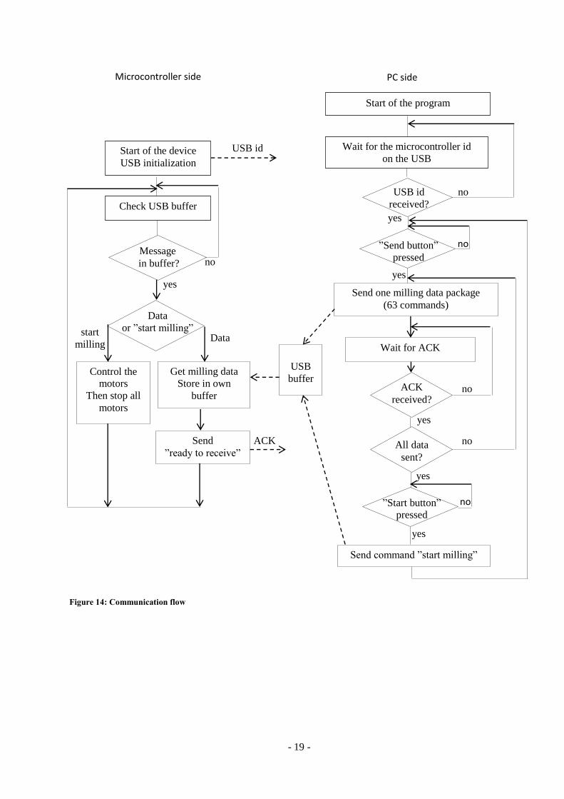
Program flow
The program flow is represented on Figure 14 below. When the microcontroller is started it waits for
the USB to be initialized. It then waits for incoming commands from the PC user interface. Each
message between the PC running the interface program and the microcontroller consists of 64 data
words; with the first data word defining the content of the message. The content can either be
commands to be stored, a program start or an emergency stop.
Each command consists of 8 data words, so a maximum of 7 commands can be sent per message.
After the program is uploaded, it can be started by sending a message with a start command. When the
start command is received, the microcontroller begins to execute commands, and does so until the
command queue is empty.
- 19 -
Microcontroller side PC side
Start of the device
USB initialization
Wait for the microcontroller id
on the USB
Message
in buffer?
Send one milling data package
(63 commands)
USB
buffer Get milling data
Store in own
buffer ACK
received?
Send
”ready to receive”
Send command ”start milling”
Control the
motors
Then stop all
motors
USB id
received?
Start of the program
USB id
Check USB buffer
Wait for ACK
ACK All data
sent?
Data
or ”start milling”
yes
no
no
no
no
yes
yes
yes
”Send button”
pressed
no
yes
Data start
milling
no ”Start button”
pressed
yes
Figure 14: Communication flow

- 20 -
5. Control theory choices
a. Coordinate system
When it comes to control, the PCB milling machine can be seen as a plane defined by a Cartesian
coordinate system. The rotating cutter is then a point moving between different coordinates, with the
help of the two motors attached to the x and y axis.
The chosen way of controlling the movement of the rotating cutter is to use polar coordinates, with
angle and length. By thinking in angles the different speeds needed for each of the motors can be
derived from the unit circle. This is true since each angle on the unit circle corresponds to an x value
and an y value. To convert the angle to a vector L(x,y), the following two equations are used.
(2)
(3)
Since the microcontroller chosen for this project does not have a floating point unit, additional code
is required to make the calculations. This would take a lot of time to execute. There are other solutions
to this problem and one is to limit the amount of possible angles and use look up tables. Since the unit
circle is centered in the origin, it is only necessary to store vector values for angles between 0 and 90
degrees. By identifying in which quadrant the angle is the vector can then be multiplied with -1 if
necessary, see Figure 15 below.
Since the cosinus and sinus can be derived from each other using the equations below, it is only
necessary to store vectors corresponding to either sin or cos.
(4)
(5)
In this project the travelling angle is controlled by the ratio of the two motors speed, and the number of
angle values is limited to 91, from 0 to 90. To each motor corresponds an array with 91 elements,
returning the rotational speed for a given angle value.
Cos is positive
Sin is positive
Cos is negative
Sin is positive
Cos is negative
Sin is negative
Cos is positive
Sin is negative
0
90
270
180
Figure 15: Quadrants in the unit circle

- 21 -
The 91 elements of the two arrays Xmotor and Ymotor can be calculated with the equations below,
with going from 0 to 90.
The r value is the linear speed of the rotating cutter in the plane, a constant affecting the speed of the
motors. It is set when creating the arrays, and was kept low for the first tests of the machine. I wrote a
program to create the two Xmotor and Ymotor arrays of motor speed, and then the lists of motor
speeds were implemented in the microcontroller.
b. Regulating the motors
The motors need to run at a given speed. Since the mechanical load will vary depending if the tool is
milling or not, a motor speed controller is needed. The use of a controller makes sure that the motor
rotates at the given speed: the output value of the motor is monitored, and if it differs too much from
the set value the controller will adjust the motor input. The difference between the output and the input
is called the control error.
The block diagram on Figure 16 below shows the relationship between the motor, the controller, and
the signals.
Figure 16: Principle of the controller
There are many types of controllers, using proportional (P), integrative (I), and derivative (D) factors.
To get a better regulation it is possible to use a combination of those factors to create for example a
PID controller.
For this application the chosen controller was the PID [9]. The reason was to achieve a short rise and
settling time.
c. Design of the PID controller
Creating the controller consist of 2 steps. The first step is to create a model of the motor and the
controller and to make a first calculation of the factors or use a method to derive them. It is then
necessary to apply these factors in the machine and trim them if necessary to achieve the wanted
performance.
Controller
(P, I, D)
Motor with
load
output
Σ +
-
set input motor
input
control
error
- 22 -
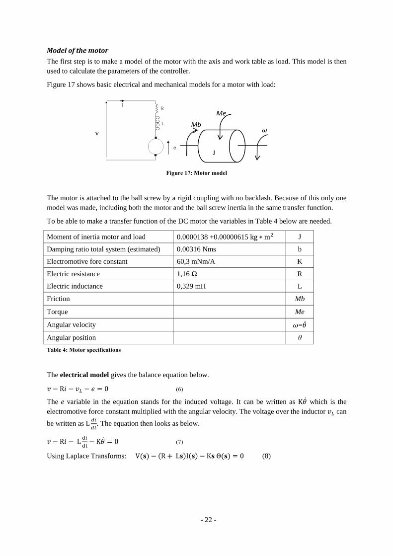
Model of the motor
The first step is to make a model of the motor with the axis and work table as load. This model is then
used to calculate the parameters of the controller.
Figure 17 shows basic electrical and mechanical models for a motor with load:
J
ω Mb
Me
Figure 17: Motor model
The motor is attached to the ball screw by a rigid coupling with no backlash. Because of this only one
model was made, including both the motor and the ball screw inertia in the same transfer function.
To be able to make a transfer function of the DC motor the variables in Table 4 below are needed.
Moment of inertia motor and load 0.0000138 +0.00000615 J
Damping ratio total system (estimated) 0.00316 Nms b
Electromotive fore constant 60,3 mNm/A K
Electric resistance 1,16 Ω R
Electric inductance 0,329 mH L
Friction Mb
Torque Me
Angular velocity =
Angular position θ
Table 4: Motor specifications
The electrical model gives the balance equation below.
(6)
The e variable in the equation stands for the induced voltage. It can be written as which is the
electromotive force constant multiplied with the angular velocity. The voltage over the inductor can
be written as
. The equation then looks as below.
(7)
Using Laplace Transforms: (8)
v

- 23 -
The mechanical model gives the following equation:
(9)
The torque is the same as the electromotive force constant multiplied with the current . The
friction can be written as which is the damping ratio multiplied with the rotational speed.
(10)
Using Laplace Transforms: (11)
After some calculations using equations (8) and (11), the transfer function for the motor can be seen as
below.
(12)
Controller model
I chose the PID controller, with the following transfer function.
(
) (13)
The model of the motor and the PID controller was simulated in Scilab Xcos, and the Ziegler-Nichols
[10] tuning was applied. The following factors were found:
Kp = 2.5
Ti = 0.11 s
Td = 0.0412 s
These values were later implemented in the microcontroller, and some tuning was made for each axis.
Sampling time
When testing running with the regulator I noticed that the process itself was quite rigid: it was stable
with good performance over a wider area than my initial expectation. However, I noticed a problem
when making a 90 or 180 degrees turn: there was a small delay before the change of direction because
of the low sampling frequency (100Hz).
In this case, the sampling frequency decides how often the regulator is activated. When it is activated
the regulator checks how many pulses came from the motor since the last check. The amount of pulses
is then compared to the set point, the wanted speed. The sampling frequency was set low because of
the low amount of pulses per revolution coming from the encoder.
One revolution of the ball screw corresponds to a linear distance of 5mm; it also corresponds to 2000
pulses sent from the incremental encoder. After checking experimentally how many pulses nb_pulses
were received from the encoders during the delay, the error in travel can then be calculated as follow:
(
) (14)
- 24 -
The solution I implemented to reduce the delay was to reduce the speed just before an incoming turn
to allow the process to react fast enough. The error before the fix was about 22 pulses from the
incremental encoder, so 0,055mm, after implementing the speed reduction it went down to 4 pulses
which correspond to 0.01mm.
This delay problem could also be solved by using a different way of control or by choosing an encoder
with higher resolution. Using higher resolution on the encoders would enable higher sampling
frequency, but those encoders are much more expensive.
IV. Results
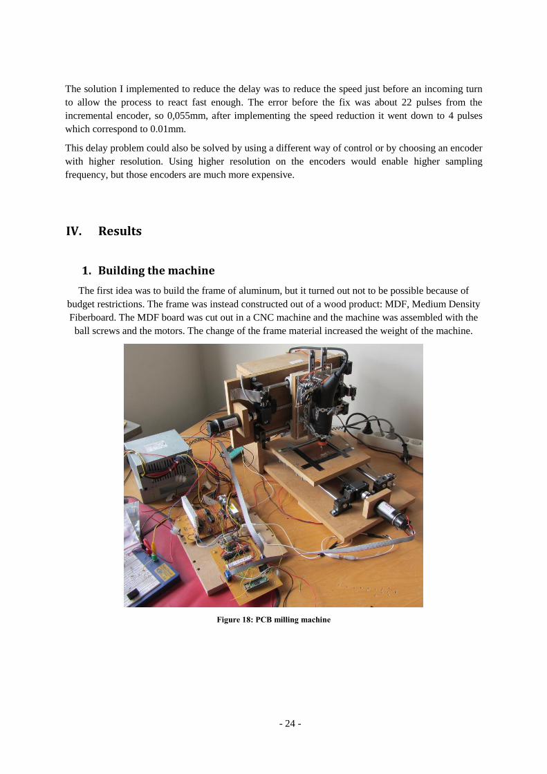
1. Building the machine
The first idea was to build the frame of aluminum, but it turned out not to be possible because of
budget restrictions. The frame was instead constructed out of a wood product: MDF, Medium Density
Fiberboard. The MDF board was cut out in a CNC machine and the machine was assembled with the
ball screws and the motors. The change of the frame material increased the weight of the machine.
Figure 18: PCB milling machine

- 25 -
On Figure 19 below it is possible to see the x-axis motor coupled to the screw through an Oldham
coupling. The end sensor for this side of the axis is also visible on the top.
Figure 19: PCB milling machine
2. Testing the machine
As a first try to command the machine, I attached a pen instead of the milling tool and drew the circuit
on a paper. This gave good results, with acceptable precision.
However, milling a board is not as easy. I used a low cost solution to attach the rotating cutter and the
servo, consisting of drawer guiding rails and springs. It does work to control the rotating cutter up and
down but the cutter is coming down too fast on the board, damaging and finally breaking the milling
tool. It is also hard to adjust the lower position of the milling tool to remove the right amount of
material from the board.
The result when milling a board can be seen on Figure 20.
Figure 20: PCB

- 26 -
3. Evaluation and discussion
The goal of this thesis was to test if I could apply the knowledge I gained during my education to
build, from scratch, some kind of “mechatronics machine”. The choice of a PCB milling machine was
made because it seemed like a good combination of mechanics, electronics, programming, and control.
It is also relatively affordable and not too big, and I plan to use it to mill PCBs for some future
projects.
I consider that this project has been successful; the machine is up and running, even if needing quite a
few improvements. It was however not as easy as I expected: the theory in itself was not a problem,
but it was when interacting with the “industry world” that it became complicated. The part I
underestimated the most was definitely the time needed to select suppliers, parts, and components.
Future work
I will not list here all the work that can be done to improve the machine, since there is so much that
can be done! However there are two main points interfering with the usability of the machine: the third
axis for the rotating cutter has to be replaced for a better solution, and the user interface should be
more user friendly. It will be changed so that it can convert files into instructions to be sent to the
microcontroller.
i
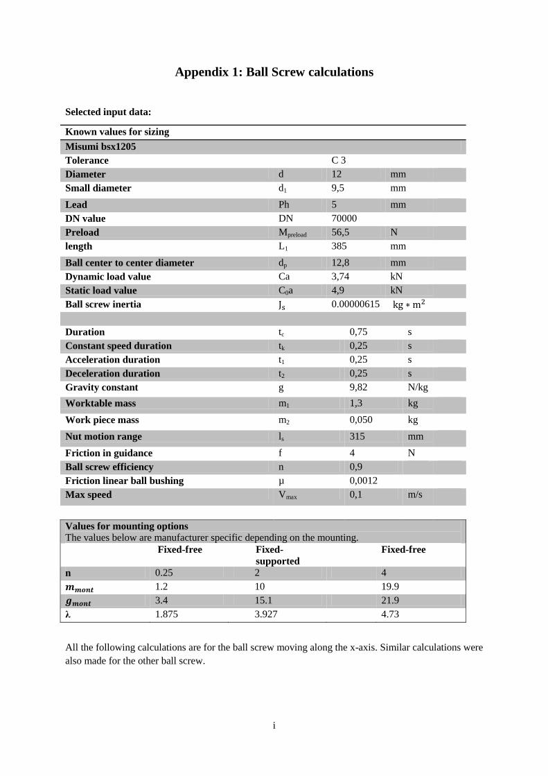
Appendix 1: Ball Screw calculations
Selected input data:
Known values for sizing
Misumi bsx1205
Tolerance C 3
Diameter d 12 mm
Small diameter d1 9,5 mm
Lead Ph 5 mm
DN value DN 70000
Preload Mpreload 56,5 N
length L1 385 mm
Ball center to center diameter dp 12,8 mm
Dynamic load value Ca 3,74 kN
Static load value C0a 4,9 kN
Ball screw inertia 0.00000615
Duration tc 0,75 s
Constant speed duration tk 0,25 s
Acceleration duration t1 0,25 s
Deceleration duration t2 0,25 s
Gravity constant g 9,82 N/kg
Worktable mass m1 1,3 kg
Work piece mass m2 0,050 kg
Nut motion range ls 315 mm
Friction in guidance f 4 N
Ball screw efficiency n 0,9
Friction linear ball bushing µ 0,0012
Max speed Vmax 0,1 m/s
Values for mounting options
The values below are manufacturer specific depending on the mounting.
Fixed-free Fixed-
supported
Fixed-free
n 0.25 2 4
1.2 10 19.9
3.4 15.1 21.9
λ 1.875 3.927 4.73
All the following calculations are for the ball screw moving along the x-axis. Similar calculations were
also made for the other ball screw.

ii
1. Estimate of the length of the ball screw The ball screw can be divided into two parts, the threaded part and the machined part. The threaded
length is calculated as the wanted stroke plus the length of the nut and an additional safety length. The
safety length is used to make sure that the nut never travels further than the thread since this may
result in a destroyed ball screw. In this case it is done using end sensors cutting power to the motors.
The machined part is where the ball screw will be mounted on the support bearings on the frame.
Illustration 1: Threaded and machined parts
Machined part length lb 70 mm
Total ball screw length l 385 mm
Ball screw length between fix points la 330 mm
Table 1: Data for length calculation
2. Maximum axis force during operation The acceleration is calculated first. With the acceleration, the estimated forces during acceleration,
constant speed and deceleration, are calculated according to equations 1 to 7. The results are in the
Table 2 below.
Acceleration:
(1)
Acceleration positive direction:
(2)
At constant speed positive direction:
(3)
Deceleration positive direction:
– (4)
Acceleration negative direction:
– – – (5)
iii
At constant speed negative direction:
– – (6)
Deceleration negative direction:
– (7)
Acceleration α 0,40 m/s2
Acceleration positive direction Fa1 4,6 N
At constant speeds positive direction Fa2 4,1 N
Deceleration positive direction Fa3 3,5 N
Acceleration negative direction Fa4 -4,6 N
At constant speeds negative direction Fa5 -4,1 N
Deceleration negative direction Fa6 -3,5 N
Highest axial force Fa max 4,6 N
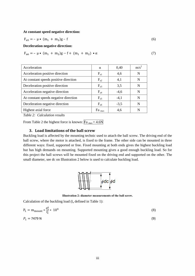
Table 2: Calculation results
From Table 2 the highest force is known: Fa max = 4.6N
3. Load limitations of the ball screw Buckling load is affected by the mounting technic used to attach the ball screw. The driving end of the
ball screw, where the motor is attached, is fixed to the frame. The other side can be mounted in three
different ways: fixed, supported or free. Fixed mounting at both ends gives the highest buckling load
but has high demands on mounting. Supported mounting gives a good enough buckling load. So for
this project the ball screws will be mounted fixed on the driving end and supported on the other. The
small diameter, see dc on Illustration 2 below is used to calculate buckling load.
Illustration 2: diameter measurements of the ball screw.
Calculation of the buckling load (la defined in Table 1):
(8)
7479 N (9)
iv
4. Maximum rotational speed The highest rotational speed is affected by two factors: a limit selected by the manufacturer and the
ball screw natural frequency.
Ball screw natural frequency
If a ball screw is rotated at the natural frequency, vibrations can damage the components. To avoid
this, the rotational speed for the natural frequency is calculated. A safety margin of 0,8 is included in
the equation 10 to assure that this speed is never reached.
(10)
131726 rpm
Rotational limit:
The manufacturer’s rotational limit depends on the manufacturing process: grinded or rolled. This
value is divided with the small diameter.
5468 rpm (11)
5. Life Span To be able to calculate average life span, the average load must first be calculated. The average load is
calculated as the total load given a repetition. The preload must also be added. In this case the exact
preload is not given. The datasheet specifies a maximum and a minimum and for this calculation the
maximum is used since it gives the lower life span. The maximum preload value is 56,5N.
The travel length from the acceleration, constant speed and deceleration must be calculated. These
travel length can be calculated from equations 12 and 13. The value for the acceleration α is found in
Table 2.
(12)
(13)
Acceleration travel length is 12.5mm and 25mm at constant speed. Deceleration travel length is the
same as the acceleration travel length.
The average load in positive direction is calculated from equation (14), and for average load in
negative direction is calculated from (15). and .
√
(14)
√|
| | | |
|
(15)
The result for both equations (14) and (15) is 56,5N.
In equation 16 below, the life span of the ball screw is calculated. The average rotation per min is
set to 1200. The work factor is selected as 2. average load is 56,5N. is the basic dynamic
load rating 3740N.
(16)
Result of the calculation above gives a life span of 500000h.
v
6. Calculation of required torque The needed torque can be divided in three parts: first the torque for the external load, then the torque
caused by the preload, and at last the torque needed for acceleration. To be able to choose a suitable
motor the average torque is also calculated.
The torque needed to move the external load is calculated in equation 17 below. The value comes
from Table 2, and is the maximum axial load.
(17)
Torque required for the preload from the datasheet:
To calculate the torque needed for acceleration the equation below is used, is the angular
acceleration and the inertia of the ball screw with motor and worktable and work material.
(18)
In equation 19 below the inertia is calculated. The A variable is if gears are used but since it is not
used this variable will be set to 1. is the ball screws inertia and the motor inertia 0.0000138
. Since there are no gears the gear inertia is 0.
(
) (19)
.
Angular acceleration:
⁄ (20)
Finally equation 18 can be calculated:
The necessary torque during uniform motion is given by equation 21 below.
(21)
The necessary torque during accelerating motion is given by equation 22 below.
(22)
The necessary torque during decelerating motion is given by equation 23 below.
(23)
With the three torques known, the average torque can be calculated in equation 24 below. This value is
important, the select motor must have a maximum continuous torque higher than this to not over heat.
√
(24)

Appendix 2: Ball Screw BSX1205

Appendix 3: Maxon Motor

Appendix 4: Electronic schematics


Bibliography
[1] MG Chemicals: Instructions for the Basic Positive Prototyping Process.
http://www.mgchemicals.com/techsupport/proto_pos-inst.html
[2] THK Ball Screw General Catalog. Preload p.705.
http://www.thk.com/documents/uk_pdf/product/general/a/ee_A15.pdf
[3] Faulhaber Optical encoder.
http://www.faulhaber.com/uploadpk/EN_HEDL_DFF.pdf
[4] THK Ball Screw General Catalog. Efficiency p.682.
http://www.thk.com/documents/uk_pdf/product/general/a/ee_A15.pdf
[5] THK Ball Screw General Catalog. Fast feed p.688.
http://www.thk.com/documents/uk_pdf/product/general/a/ee_A15.pdf
[6] Maxon motors. MAXON DC MOTOR.
http://www.maxonmotor.com/medias/sys_master/8798978179102/maxonDCmotor_Notes.pdf?mime=
application%2Fpdf&realname=maxonDCmotor_Notes.pdf
[7] Sedra, A and Smith, K. (2004) Microelectronics circuits, Fifth edition. pp.235-359.
[8] ATMEL PWM
www.atmel.com/Images/doc2542.pdf
[9] Lennartson, B. (2006) Reglerteknikens grunder, Fjärde upplagan. p.326.
[10] Lennartson, B. (2006) Reglerteknikens grunder, Fjärde upplagan. p.342.