Embed Size (px)
Citation preview
US Army Corps of Engineers
BUILDING STRONG®
Innovative solutions for a safer, better worldBUILDING STRONG®
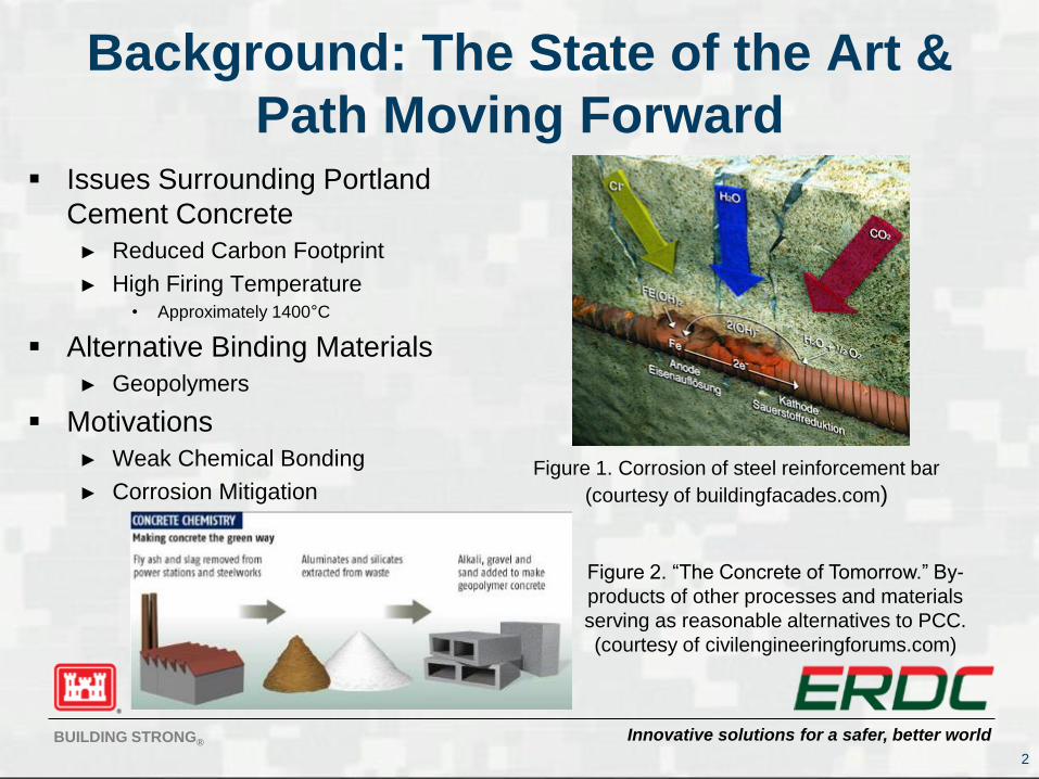
Background: The State of the Art &
Path Moving Forward Issues Surrounding Portland
Cement Concrete
► Reduced Carbon Footprint
► High Firing Temperature• Approximately 1400°C
Alternative Binding Materials
► Geopolymers
Motivations
► Weak Chemical Bonding
► Corrosion Mitigation
2
Figure 1. Corrosion of steel reinforcement bar
(courtesy of buildingfacades.com)
Figure 2. “The Concrete of Tomorrow.” By-
products of other processes and materials
serving as reasonable alternatives to PCC.
(courtesy of civilengineeringforums.com)
Innovative solutions for a safer, better worldBUILDING STRONG®
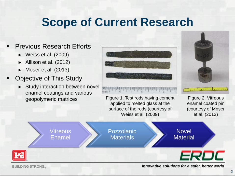
Scope of Current Research
Previous Research Efforts
► Weiss et al. (2009)
► Allison et al. (2012)
► Moser et al. (2013)
Objective of This Study
► Study interaction between novel
enamel coatings and various
geopolymeric matrices
3
Vitreous Enamel
Pozzolanic Materials
Novel Material
Figure 2. Vitreous
enamel coated pin
(courtesy of Moser
et al. (2013)
Figure 1. Test rods having cement
applied to melted glass at the
surface of the rods (courtesy of
Weiss et al. (2009)
Innovative solutions for a safer, better worldBUILDING STRONG®
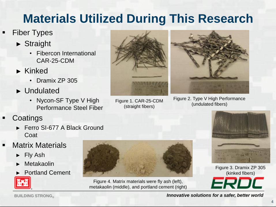
Materials Utilized During This Research Fiber Types
► Straight
• Fibercon International
CAR-25-CDM
► Kinked
• Dramix ZP 305
► Undulated
• Nycon-SF Type V High
Performance Steel Fiber
Coatings
► Ferro SI-677 A Black Ground
Coat
Matrix Materials
► Fly Ash
► Metakaolin
► Portland Cement
4
Figure 1. CAR-25-CDM
(straight fibers)
Figure 3. Dramix ZP 305
(kinked fibers)
Figure 2. Type V High Performance
(undulated fibers)
Figure 4. Matrix materials were fly ash (left),
metakaolin (middle), and portland cement (right)
Innovative solutions for a safer, better worldBUILDING STRONG®
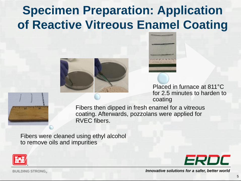
Specimen Preparation: Application
of Reactive Vitreous Enamel Coating
5
Fibers were cleaned using ethyl alcohol to remove oils and impurities
Fibers then dipped in fresh enamel for a vitreous coating. Afterwards, pozzolans were applied for RVEC fibers.
Placed in furnace at 811°C for 2.5 minutes to harden to coating
Innovative solutions for a safer, better worldBUILDING STRONG®
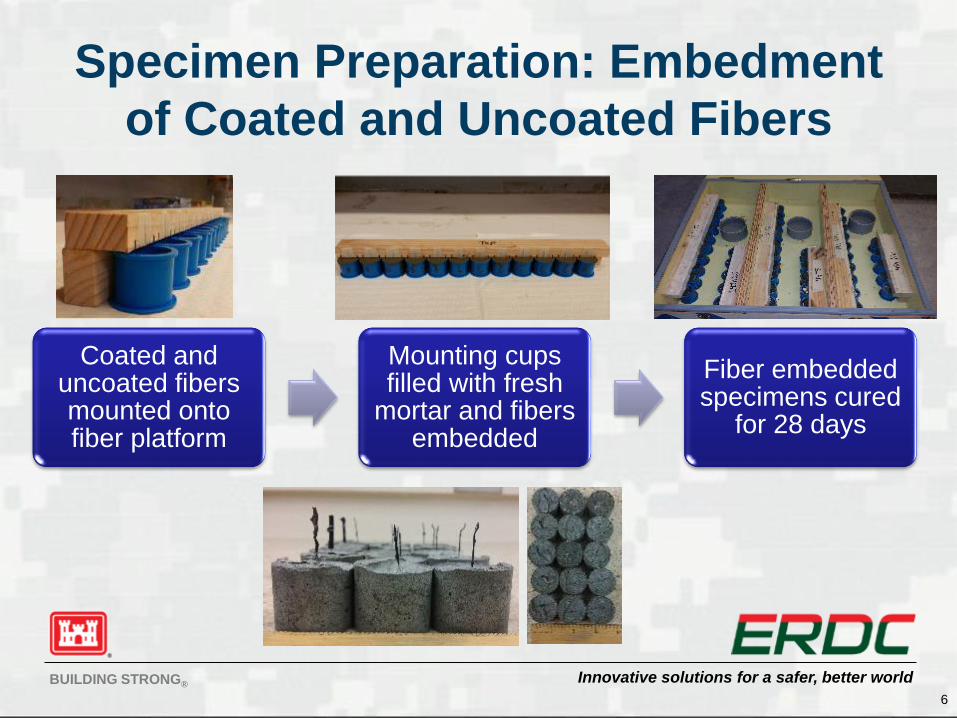
Specimen Preparation: Embedment
of Coated and Uncoated Fibers
6
Coated and uncoated fibers mounted onto fiber platform
Mounting cups filled with fresh
mortar and fibers embedded
Fiber embedded specimens cured
for 28 days
Innovative solutions for a safer, better worldBUILDING STRONG®
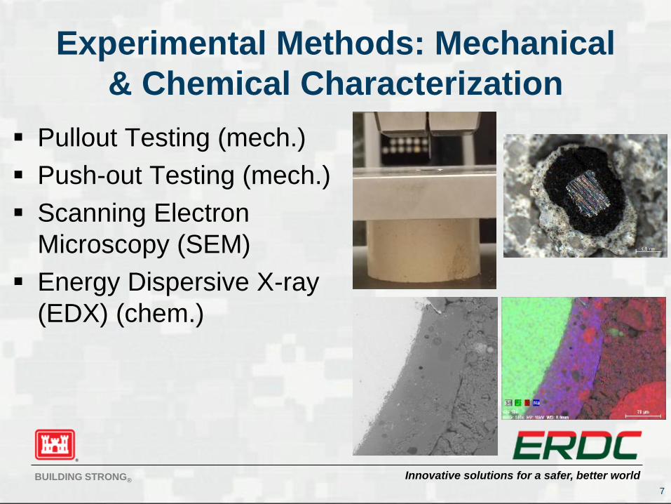
Experimental Methods: Mechanical
& Chemical Characterization
Pullout Testing (mech.)
Push-out Testing (mech.)
Scanning Electron
Microscopy (SEM)
Energy Dispersive X-ray
(EDX) (chem.)
7
Innovative solutions for a safer, better worldBUILDING STRONG®
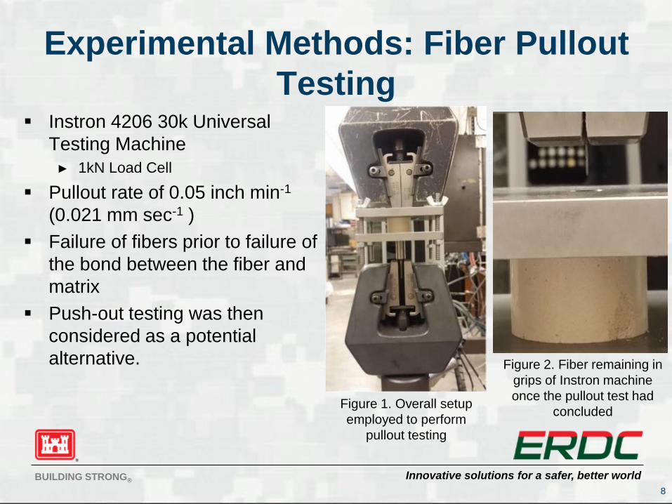
Experimental Methods: Fiber Pullout
Testing Instron 4206 30k Universal
Testing Machine
► 1kN Load Cell
Pullout rate of 0.05 inch min-1
(0.021 mm sec-1 )
Failure of fibers prior to failure of
the bond between the fiber and
matrix
Push-out testing was then
considered as a potential
alternative.
8
Figure 1. Overall setup
employed to perform
pullout testing
Figure 2. Fiber remaining in
grips of Instron machine
once the pullout test had
concluded
Innovative solutions for a safer, better worldBUILDING STRONG®
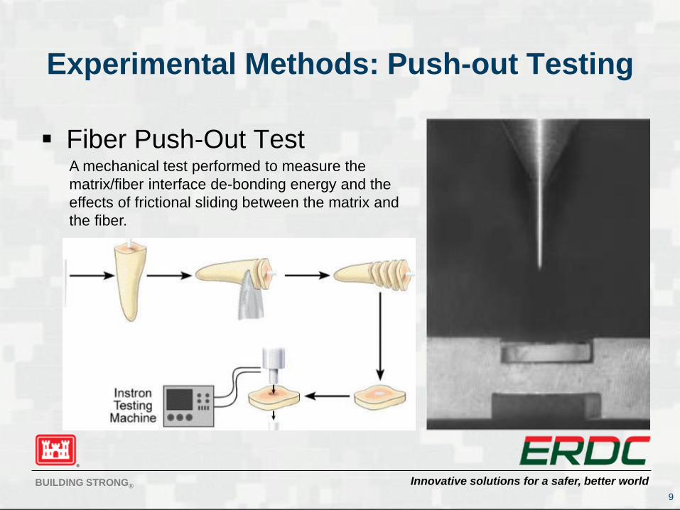
Experimental Methods: Push-out Testing
Fiber Push-Out Test
9
A mechanical test performed to measure the
matrix/fiber interface de-bonding energy and the
effects of frictional sliding between the matrix and
the fiber.
Innovative solutions for a safer, better worldBUILDING STRONG®
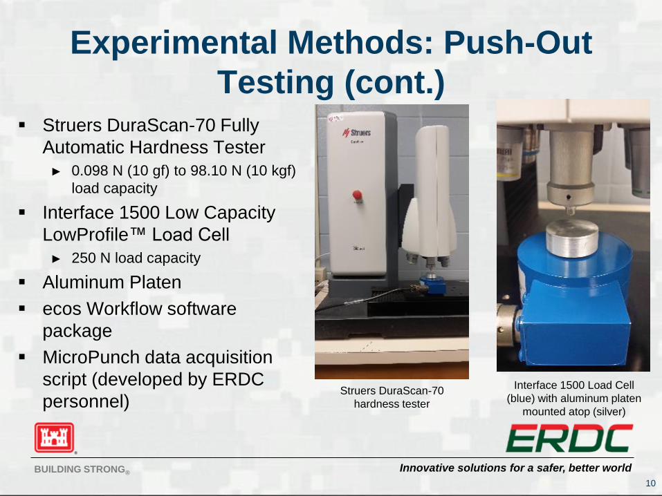
Experimental Methods: Push-Out
Testing (cont.)
10
Struers DuraScan-70 Fully
Automatic Hardness Tester
► 0.098 N (10 gf) to 98.10 N (10 kgf)
load capacity
Interface 1500 Low Capacity
LowProfile™ Load Cell
► 250 N load capacity
Aluminum Platen
ecos Workflow software
package
MicroPunch data acquisition
script (developed by ERDC
personnel)Struers DuraScan-70
hardness tester
Interface 1500 Load Cell
(blue) with aluminum platen
mounted atop (silver)
Innovative solutions for a safer, better worldBUILDING STRONG®
Experimental Methods: Push-Out
Testing (cont.)
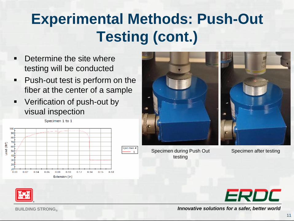
Determine the site where
testing will be conducted
Push-out test is perform on the
fiber at the center of a sample
Verification of push-out by
visual inspection
11
Specimen during Push Out
testing
Specimen after testing
Innovative solutions for a safer, better worldBUILDING STRONG®
Experimental Methods: SEM and
EDX Spectroscopy
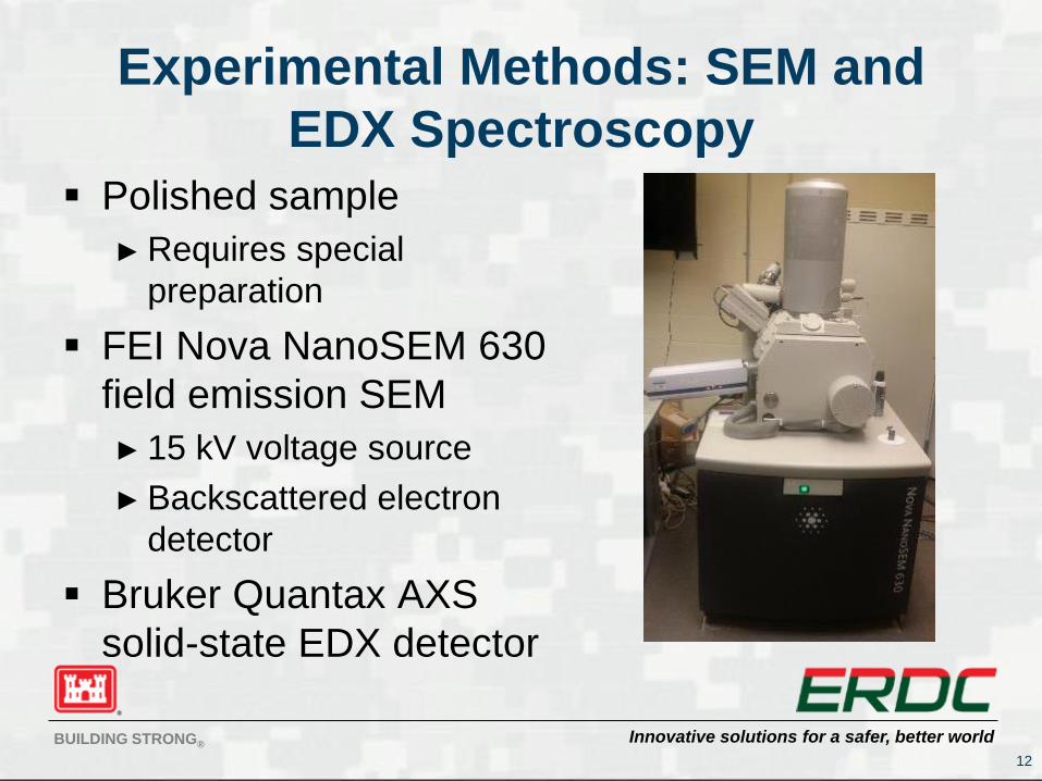
Polished sample
► Requires special
preparation
FEI Nova NanoSEM 630
field emission SEM
► 15 kV voltage source
► Backscattered electron
detector
Bruker Quantax AXS
solid-state EDX detector
12
Innovative solutions for a safer, better worldBUILDING STRONG®
Results & Discussion: Pullout
Testing
13
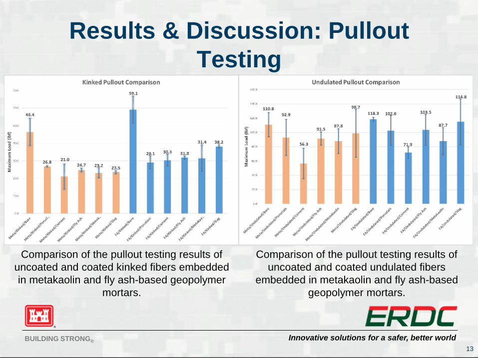
Comparison of the pullout testing results of
uncoated and coated kinked fibers embedded
in metakaolin and fly ash-based geopolymer
mortars.
Comparison of the pullout testing results of
uncoated and coated undulated fibers
embedded in metakaolin and fly ash-based
geopolymer mortars.
Innovative solutions for a safer, better worldBUILDING STRONG®
Results & Discussion: Pullout Testing (cont.)
14
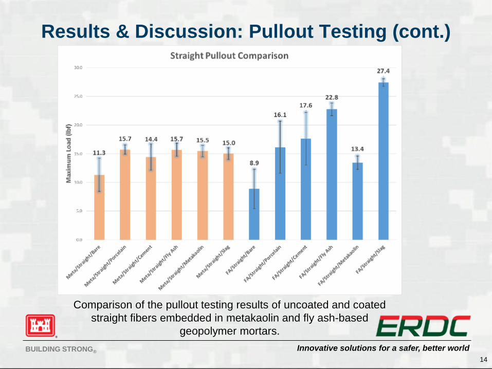
Comparison of the pullout testing results of uncoated and coated
straight fibers embedded in metakaolin and fly ash-based
geopolymer mortars.
Innovative solutions for a safer, better worldBUILDING STRONG®
Results & Discussion: Optical
Microscopy of Fibers Post-Pullout Test
15
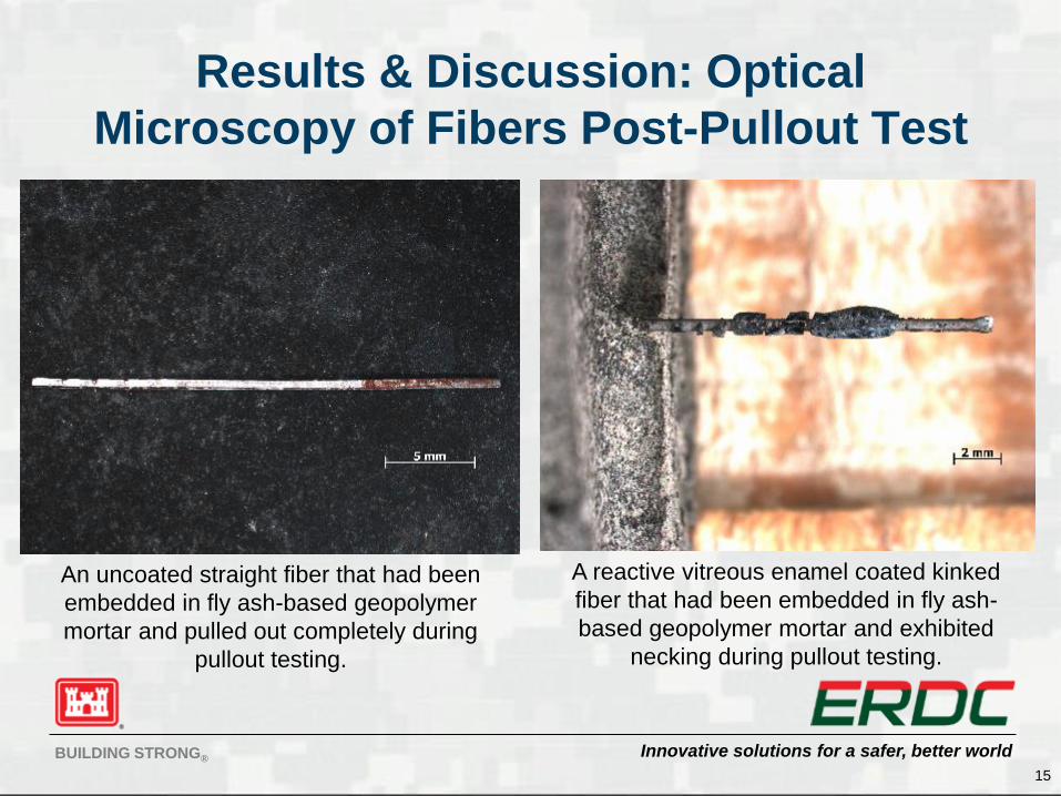
An uncoated straight fiber that had been
embedded in fly ash-based geopolymer
mortar and pulled out completely during
pullout testing.
A reactive vitreous enamel coated kinked
fiber that had been embedded in fly ash-
based geopolymer mortar and exhibited
necking during pullout testing.
Innovative solutions for a safer, better worldBUILDING STRONG®
Results & Discussion: Optical
Microscopy of Fibers Post-Pullout Test
(cont.)
16
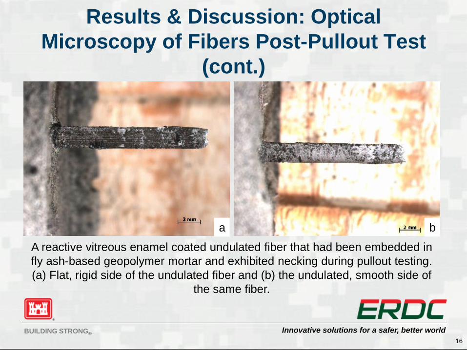
A reactive vitreous enamel coated undulated fiber that had been embedded in
fly ash-based geopolymer mortar and exhibited necking during pullout testing.
(a) Flat, rigid side of the undulated fiber and (b) the undulated, smooth side of
the same fiber.
a b
Innovative solutions for a safer, better worldBUILDING STRONG®
Small Study: Tensile Tests Performed on
Each Fiber Type Under Various Treatments
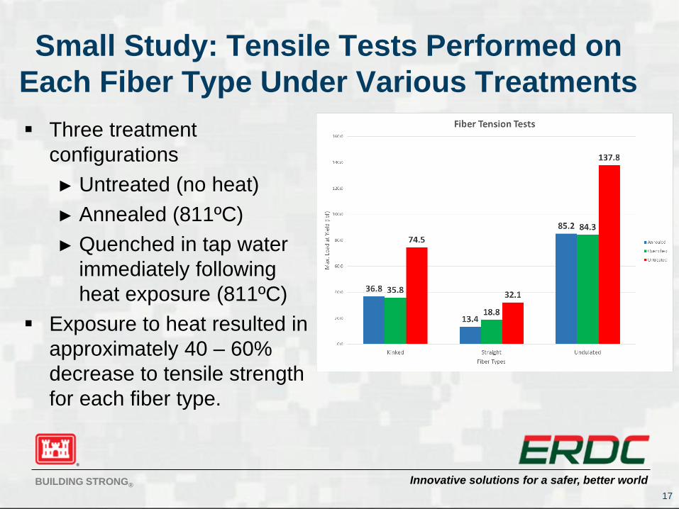
Three treatment
configurations
► Untreated (no heat)
► Annealed (811ºC)
► Quenched in tap water
immediately following
heat exposure (811ºC)
Exposure to heat resulted in
approximately 40 – 60%
decrease to tensile strength
for each fiber type.
17
Innovative solutions for a safer, better worldBUILDING STRONG®
Lessons Learned from Pullout
Testing…
18
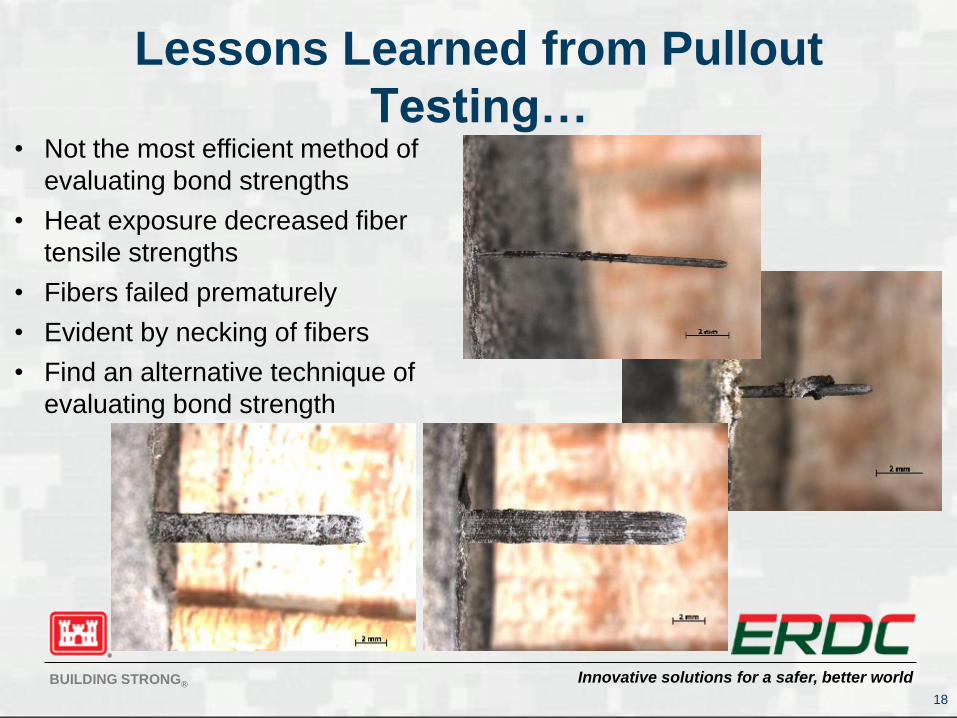
• Not the most efficient method of
evaluating bond strengths
• Heat exposure decreased fiber
tensile strengths
• Fibers failed prematurely
• Evident by necking of fibers
• Find an alternative technique of
evaluating bond strength
Innovative solutions for a safer, better worldBUILDING STRONG®
Results & Discussion: Push-Out
Testing
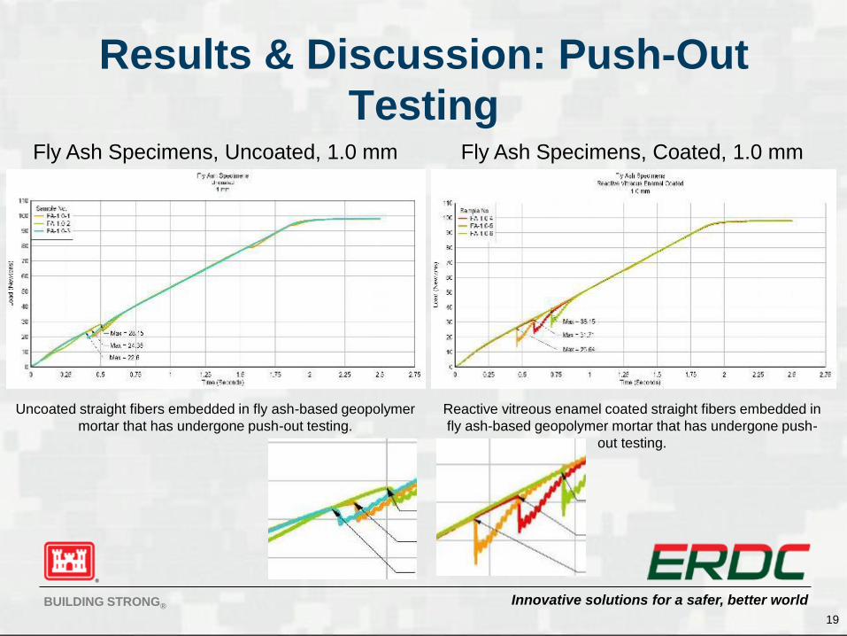
19
Uncoated straight fibers embedded in fly ash-based geopolymer
mortar that has undergone push-out testing.
Reactive vitreous enamel coated straight fibers embedded in
fly ash-based geopolymer mortar that has undergone push-
out testing.
Fly Ash Specimens, Uncoated, 1.0 mm Fly Ash Specimens, Coated, 1.0 mm
Innovative solutions for a safer, better worldBUILDING STRONG®
Results & Discussion: Push-Out
Testing (cont.)
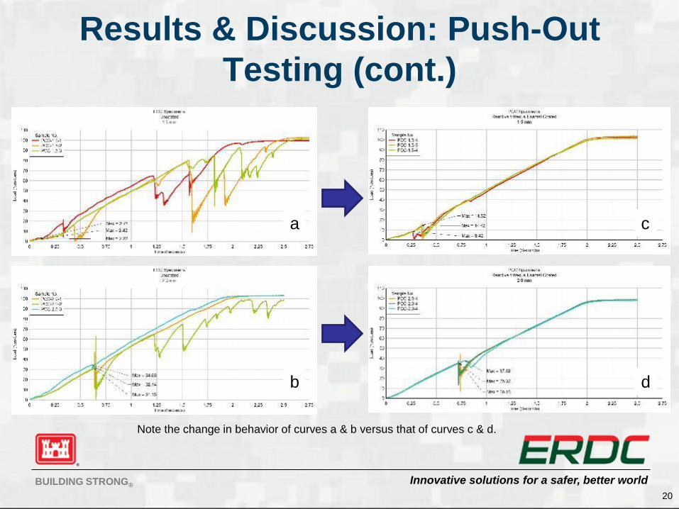
20
Note the change in behavior of curves a & b versus that of curves c & d.
a
b d
c
Innovative solutions for a safer, better worldBUILDING STRONG®
Results & Discussion: Optical
Microscopy of Push-Out Specimens
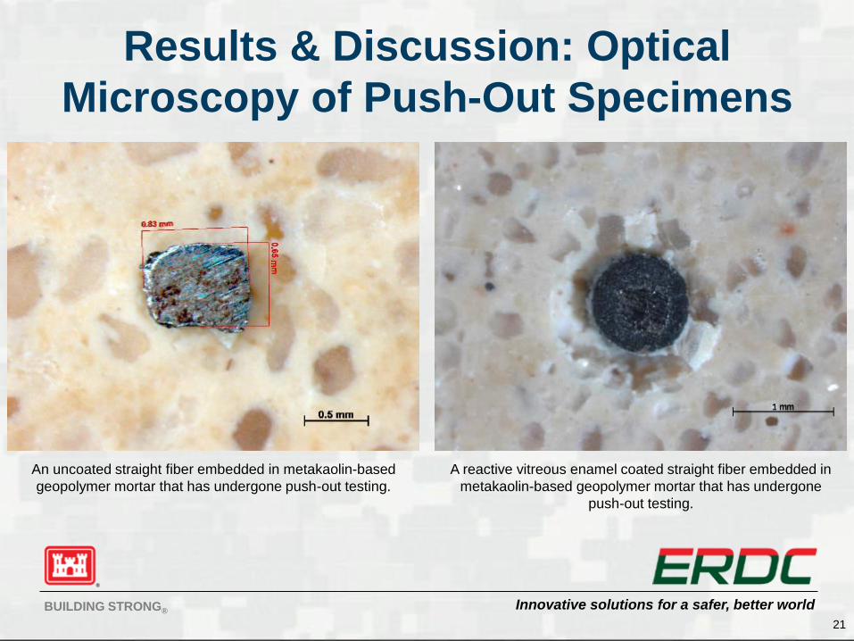
21
An uncoated straight fiber embedded in metakaolin-based
geopolymer mortar that has undergone push-out testing.
A reactive vitreous enamel coated straight fiber embedded in
metakaolin-based geopolymer mortar that has undergone
push-out testing.
Innovative solutions for a safer, better worldBUILDING STRONG®
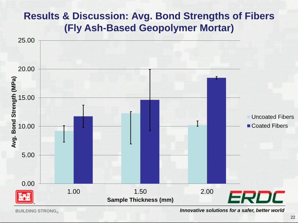
Results & Discussion: Avg. Bond Strengths of Fibers
(Fly Ash-Based Geopolymer Mortar)
22
0.00
5.00
10.00
15.00
20.00
25.00
1.00 1.50 2.00
Avg
. B
on
d S
tre
ng
th (
MP
a)
Sample Thickness (mm)
Uncoated Fibers
Coated Fibers
Innovative solutions for a safer, better worldBUILDING STRONG®
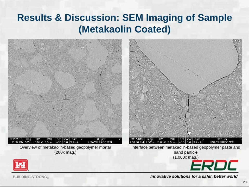
Results & Discussion: SEM Imaging of Sample
(Metakaolin Coated)
23
Overview of metakaolin-based geopolymer mortar
(200x mag.)
Interface between metakaolin-based geopolymer paste and
sand particle
(1,000x mag.)
Innovative solutions for a safer, better worldBUILDING STRONG®
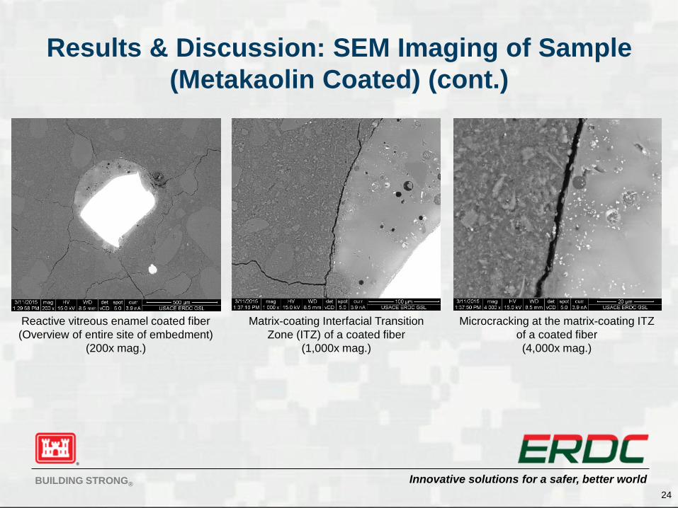
Results & Discussion: SEM Imaging of Sample
(Metakaolin Coated) (cont.)
24
Reactive vitreous enamel coated fiber
(Overview of entire site of embedment)
(200x mag.)
Matrix-coating Interfacial Transition
Zone (ITZ) of a coated fiber
(1,000x mag.)
Microcracking at the matrix-coating ITZ
of a coated fiber
(4,000x mag.)
Innovative solutions for a safer, better worldBUILDING STRONG®
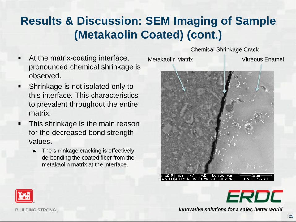
Results & Discussion: SEM Imaging of Sample
(Metakaolin Coated) (cont.)
At the matrix-coating interface,
pronounced chemical shrinkage is
observed.
Shrinkage is not isolated only to
this interface. This characteristics
to prevalent throughout the entire
matrix.
This shrinkage is the main reason
for the decreased bond strength
values.► The shrinkage cracking is effectively
de-bonding the coated fiber from the
metakaolin matrix at the interface.
25
Chemical Shrinkage Crack
Metakaolin Matrix Vitreous Enamel

Innovative solutions for a safer, better worldBUILDING STRONG®
Results & Discussion: Energy Dispersive X-ray
(EDX) Spectroscopy
(Metakaolin Specimen)
26
Line scan and elemental mapping of Matrix-Enamel-
Fiber Interfacial Transition Zones (ITZs)
Innovative solutions for a safer, better worldBUILDING STRONG®
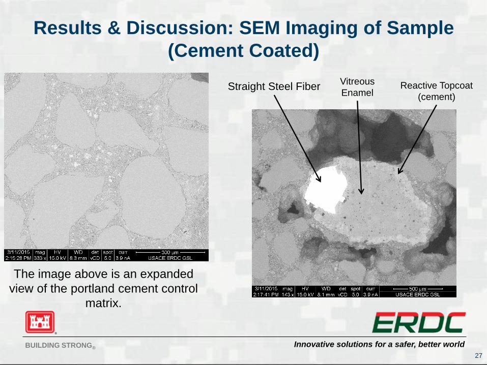
Results & Discussion: SEM Imaging of Sample
(Cement Coated)
27
Straight Steel FiberVitreous
EnamelReactive Topcoat
(cement)
The image above is an expanded
view of the portland cement control
matrix.
Innovative solutions for a safer, better worldBUILDING STRONG®
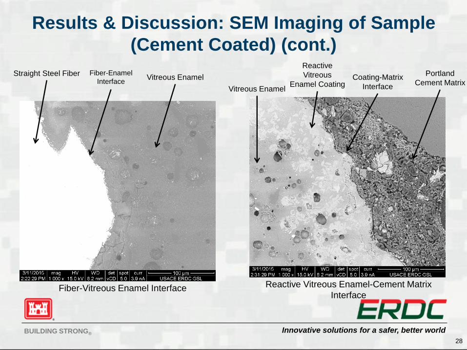
Results & Discussion: SEM Imaging of Sample
(Cement Coated) (cont.)
28
Fiber-Vitreous Enamel Interface
Straight Steel Fiber Fiber-Enamel
InterfaceVitreous Enamel
Reactive Vitreous Enamel-Cement Matrix
Interface
Vitreous Enamel
Reactive
Vitreous
Enamel CoatingCoating-Matrix
Interface
Portland
Cement Matrix
Innovative solutions for a safer, better worldBUILDING STRONG®
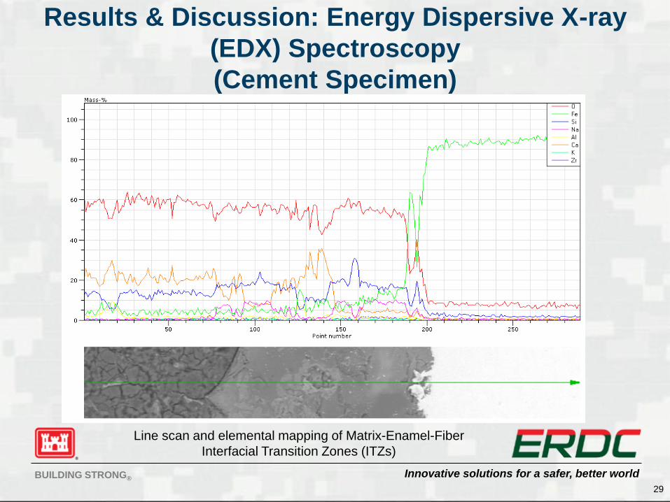
Results & Discussion: Energy Dispersive X-ray
(EDX) Spectroscopy
(Cement Specimen)
29
Line scan and elemental mapping of Matrix-Enamel-Fiber
Interfacial Transition Zones (ITZs)
Innovative solutions for a safer, better worldBUILDING STRONG®
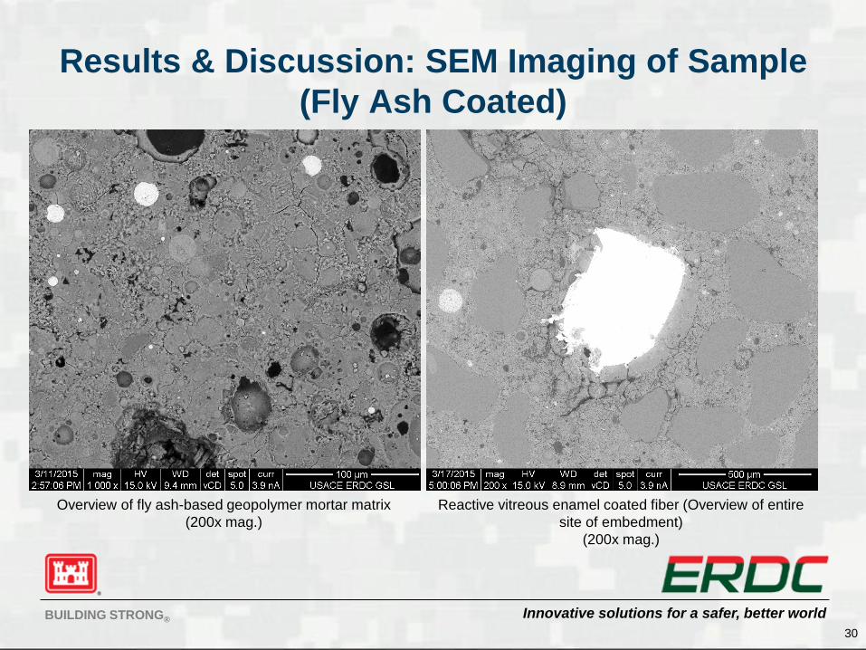
Results & Discussion: SEM Imaging of Sample
(Fly Ash Coated)
30
Overview of fly ash-based geopolymer mortar matrix
(200x mag.)
Reactive vitreous enamel coated fiber (Overview of entire
site of embedment)
(200x mag.)
Innovative solutions for a safer, better worldBUILDING STRONG®
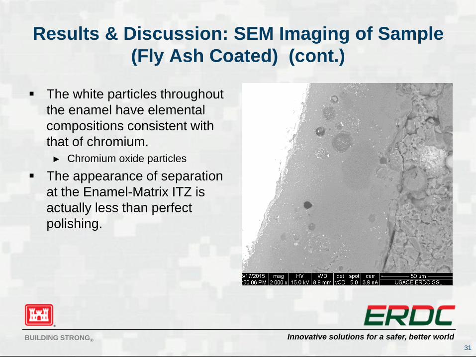
Results & Discussion: SEM Imaging of Sample
(Fly Ash Coated) (cont.)
The white particles throughout
the enamel have elemental
compositions consistent with
that of chromium.
► Chromium oxide particles
The appearance of separation
at the Enamel-Matrix ITZ is
actually less than perfect
polishing.
31
Innovative solutions for a safer, better worldBUILDING STRONG®
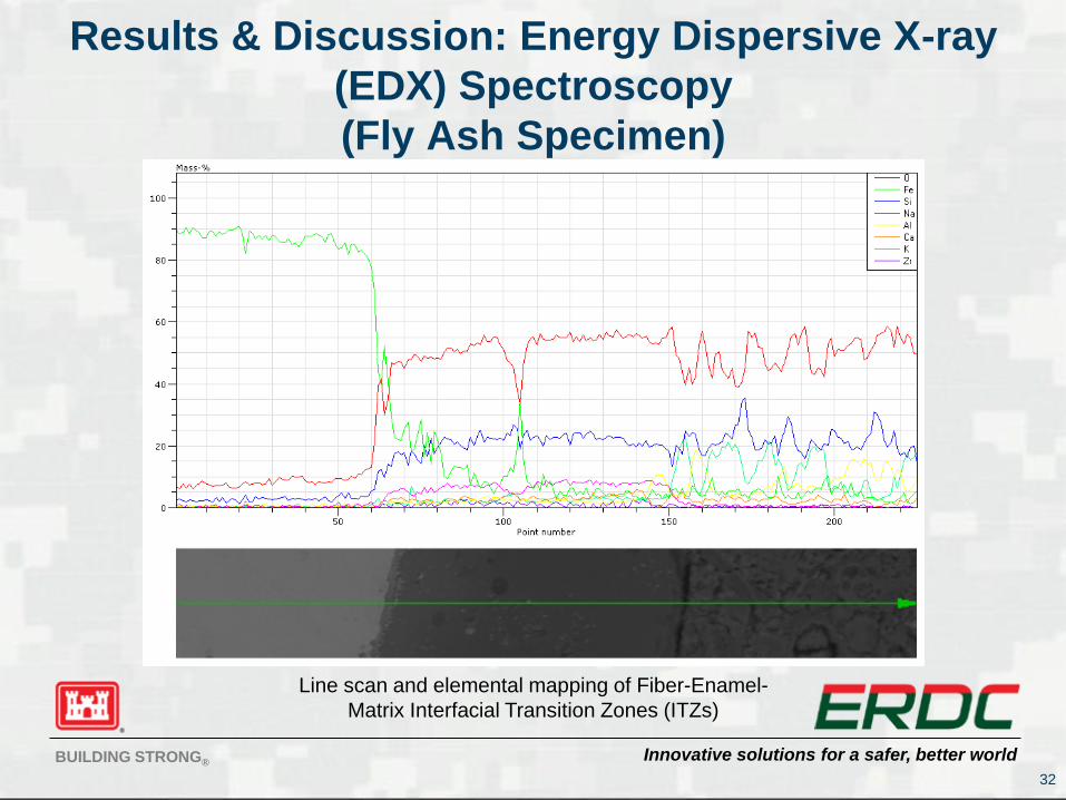
Results & Discussion: Energy Dispersive X-ray
(EDX) Spectroscopy
(Fly Ash Specimen)
32
Line scan and elemental mapping of Fiber-Enamel-
Matrix Interfacial Transition Zones (ITZs)
Innovative solutions for a safer, better worldBUILDING STRONG®
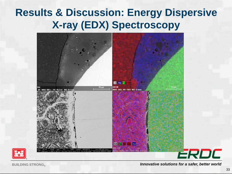
Results & Discussion: Energy Dispersive
X-ray (EDX) Spectroscopy
33
Innovative solutions for a safer, better worldBUILDING STRONG®
Conclusions Reactive vitreous enamel coating enhances bond strength on
the order of up to 5.7 times
EDX spectroscopy shows smoother transitions in elemental
composition across the ITZs of coated specimens, translating to
these higher bond strengths
Overall toughness is increased in cementitious samples
containing coated fibers versus those with uncoated fibers
Higher standards of deviation in coated samples are as a result
of the non-uniformity of the coating
Overly thick coating negates mechanical anchorage in fibers of
deformed geometries
34
Innovative solutions for a safer, better worldBUILDING STRONG®
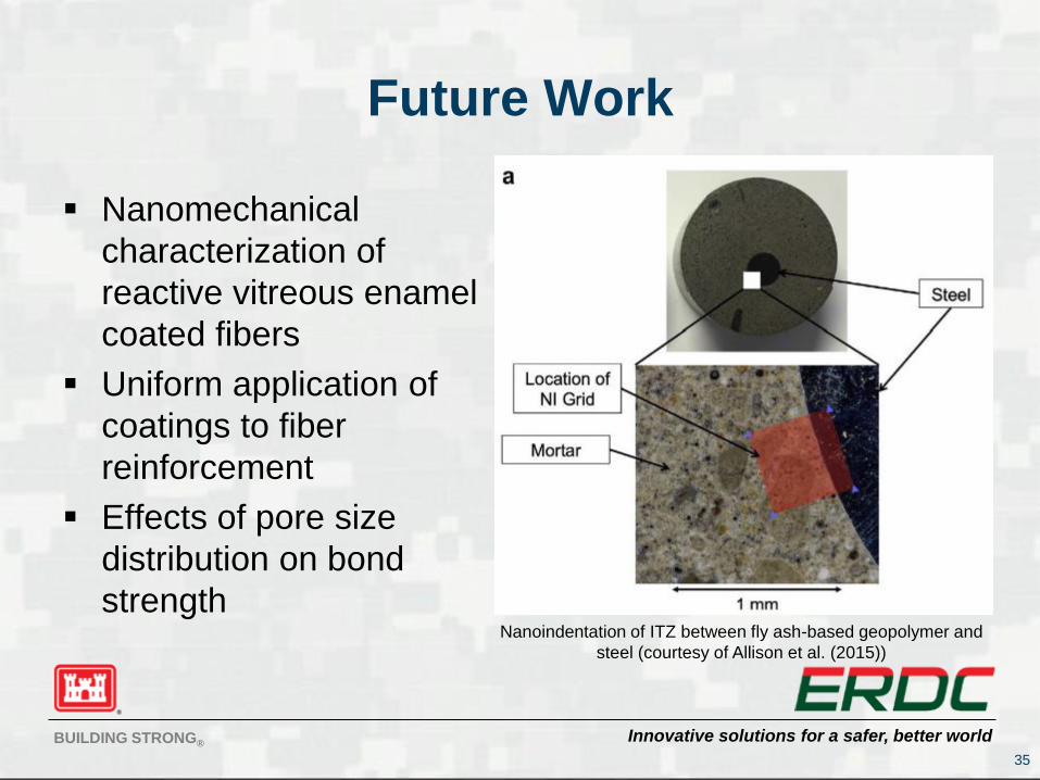
Future Work
Nanomechanical
characterization of
reactive vitreous enamel
coated fibers
Uniform application of
coatings to fiber
reinforcement
Effects of pore size
distribution on bond
strength
35
Nanoindentation of ITZ between fly ash-based geopolymer and
steel (courtesy of Allison et al. (2015))
Innovative solutions for a safer, better worldBUILDING STRONG®
Acknowledgements
U.S. ERDC Personnel
Dr. Charles A. Weiss, Jr., GSL
Dr. Robert D. Moser, GSL
Henry Blake, ITL
Kevin Torres-Cancel, GSL
Brett A. Williams, GSL
Jason Morson, GSL
Wendy Long, GSL
Stephen Murrell, GSL
Jackson State Personnel
Dr. Lin Li
Dr. Fashard Amini
Dr. Wei Zheng
Shanetta Cristler
36
I’d like to thank the ERDC 6.1 Military Engineering Basic Research
Program for providing the funding necessary to execute the research
presented herein.
Innovative solutions for a safer, better worldBUILDING STRONG®
Thank You For Listening!
Questions???
Comments???
37
Innovative solutions for a safer, better worldBUILDING STRONG®
Experimental Methods: Push-Out
Testing (cont.)
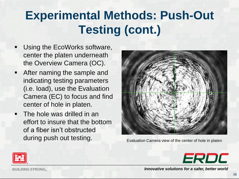
Using the EcoWorks software,
center the platen underneath
the Overview Camera (OC).
After naming the sample and
indicating testing parameters
(i.e. load), use the Evaluation
Camera (EC) to focus and find
center of hole in platen.
The hole was drilled in an
effort to insure that the bottom
of a fiber isn’t obstructed
during push out testing.
38
Evaluation Camera view of the center of hole in platen
Innovative solutions for a safer, better worldBUILDING STRONG®
Push Out Test Procedure Overview
(cont.)
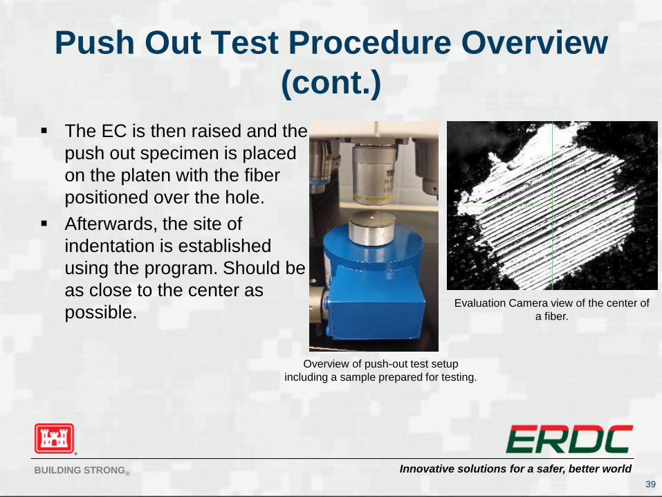
The EC is then raised and the
push out specimen is placed
on the platen with the fiber
positioned over the hole.
Afterwards, the site of
indentation is established
using the program. Should be
as close to the center as
possible.
39
Evaluation Camera view of the center of
a fiber.
Overview of push-out test setup
including a sample prepared for testing.
Innovative solutions for a safer, better worldBUILDING STRONG®
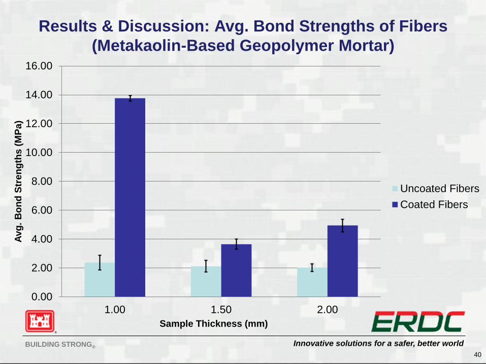
Results & Discussion: Avg. Bond Strengths of Fibers
(Metakaolin-Based Geopolymer Mortar)
40
0.00
2.00
4.00
6.00
8.00
10.00
12.00
14.00
16.00
1.00 1.50 2.00
Avg
. B
on
d S
tre
ng
ths
(M
Pa
)
Sample Thickness (mm)
Uncoated Fibers
Coated Fibers
Innovative solutions for a safer, better worldBUILDING STRONG®
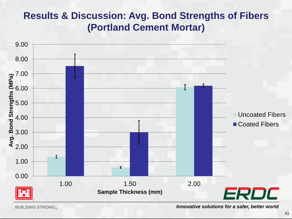
Results & Discussion: Avg. Bond Strengths of Fibers
(Portland Cement Mortar)
41
0.00
1.00
2.00
3.00
4.00
5.00
6.00
7.00
8.00
9.00
1.00 1.50 2.00
Avg
. B
on
d S
tre
ng
ths
(M
Pa
)
Sample Thickness (mm)
Uncoated Fibers
Coated Fibers